Kenmore 580.72187200 El manual del propietario
- Tipo
- El manual del propietario

Owner's Manual
Manual del Propietario
®
HEAT / COOL AIR CONDITIONER
EICALOR / REFRESCA ACONDICIONADOR
DE AIRE DE VENTANA
Model, Modelo 580.72187_o_
Sears, Roebuck and Co., Hoffman Estates, IL 60179 U.S.A.
www.sears.com

TABLE OF CONTENTS ........................2
WARRANTY .............................................2
SAFETY .....................................................3
Important Safety Instructions ...................... 3
ELECTRICAL REQUIREMENTS .......4
INSTALLATION .......................................5
Installation Requirements ......................... 5
Installation ................................................ 6
How to Instal] ............................................ 6
Removal from Window ................................. 8
OPERATION ............................................. 9
How and Why ........................................... 9
Normal Sounds ........................................ 9
Capacity and Running Time ..................... 9
Features ................................................. 10
Using the Air Conditioner ....................... 10
Display ................................................... 11
MAINTENANCE ..................................... 12
Air Filter Cleaning ................................... 12
Air Conditioner Cleaning ........................ 12
How to Replace the FrontGrille .................. 12
TROUBLESHOOTING ......................... 13
Before Calling for Service ...................... 13
REPAIR PARTS ..................................... 14
ESPAI_IOL ................................................24
SERVICE NUMBERS ....... Back Cover
FULL ONE YEAR WARRANTY ON
ROOM AIR CONDITIONER
For one year from the date of purchase, when this
air conditioner isoperated and maintained for
normal room cooling according to instructions in this
owner's manual, Sears will repair this air
conditioner, free of charge, if defective in material or
workmanship.
FULL FIVE-YEAR WARRANTY ON
SEALED REFRIGERATION SYSTEM
For five years from the date of purchase, when this
air conditioner is operated and maintained for
normal room cooling according to instructions in this
owner's manual, Sears will repair the sealed
refrigeration system (consisting of refrigerant,
connecting tubing, and compressor), free of charge,
if defective in material or workmanship.
WARRANTY SERVICE IS AVAILABLE BY
CONTACTING SEARS SERVICE AT
1-800-4-MY-HOME e
Warranty coverage applies only to air conditioners
used for non-commercial, private household
purposes.
This warranty applies only while this product is in
use in the United States.
This warranty gives you specific legal rights, and
you may also have other right which vary from state
to state.
Sears, Roebuck and Co., D/817WA,
Hoffman Estates, IL 60179 U.S.A.
-2-

IMPORTANT SAFETY INSTRUCTIONS
The safety instructions below will tell you how to use your room air conditioner to avoid harm to yourself or
damageto your ROOM AIR CONDITIONER.
FOR YOUR SAFETY
Do not store or use gasoline or other flammable
vapors and liquids in the vicinity of this or any other
appliance. Read product labels for flammability and
other warnings.
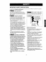
PREVENT ACCIDENTS
To reduce the risk of fire, electrical shock, or injury
to persons when using your air conditioner, follow
basic precautions, including the following:
• Be sure the electrical service is adequate for the
model you have chosen.
• If the air conditioner is to be installed in a window,
you will probably want to clean both sides of the
glass first. If the window is a triple-track type with a
screen panel included, you may want to remove
the screen completely before installation.
• Be sure the air conditioner has been securely and
correctly installed according to the separate
installation instructions provided with this manual.
Save this manual and installation instructions for
possible future use in removing or reinstalling this
unit.
• Use gloves when handling the air conditioner.
Be careful to avoid cuts from sharp metal fins on
front and rear coils.
ELECTRICAL INFORMATION
The complete electrical rating of your new room air
conditioner is stated on the serial plate. Refer to the
rating when checking the electrical requirements.
• Be sure the air conditioner is pmpedy grounded.
To minimize shock and fire hazards, proper
grounding is important. The power cord is
equipped with a three-prong grounding plug for
protection against shock hazards.
• Your air conditioner must be plugged into a
properly grounded wall receptacle. If the wall
receptacle you intend to use is notadequately
grounded or protected by a time delay fuse or
circuit breaker, have a qualified electdcian install
the proper receptacle.
• Do not run air conditioner with a protective
covering. This could result in mechanical damage
within the air conditioner.
• Do not use an extension cord or an adapter
plug.
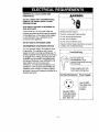
i
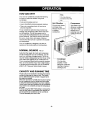
_void fire hazard or electric shock.
Do not use an extension cord or an adapter plug.
Do not remove any prong from the power cord.
Grounding type
wall Do not under any /
circumstances cut,
remove, or bypass
the grounding prong
from this plug.
Power supply cord
with 3-prong _,_
grounding plug \\
ENERGY SAVING IDEAS
• The capacity of the room air conditioner must fit
the room size for efficient and satisfactory
operation.
• Install the room air conditioner on the shady side
of your home. A window that faces north is best
because it is shaded most of the day.
• Do not block air flow inside with blinds, curtains, or
furniture, or outside with shrubs, enclosures, or
other buildings.
• Close the floor and wall registers and the fireplace
damper so cool air does not escape up the
chimney and into the duct work.
• Keep blinds and drapes in other windows closed
during the sunniest part of the day.
• Clean the air filter as recommended in the
MAINTENANCE section of this manual.
• Proper insulation and weather stripping in your
home will help keep warm air out and cool air in.
• External house shading with trees, plants or
awnings will help reduce the air conditioner's work
load.
• Operate heat producing appliances such as
ranges, washers, dryers, and dishwashers during
the coolest part of the day.
-3-

OBSERVE ALL LOCAL CODES AND
ORDINANCES.
DO NOT, UNDER ANY CIRCUMSTANCES,
REMOVETHEPOWERSUPPLYCORD
GROUND PRONG.
ELECTRICAL GROUNDIS REQUIRED ON
THIS APPLIANCE.
A 250-volt 60 Hz, AC only, 20A fused and
properly grounded electrical supply is required.
A time delay fuse or time delay circuit breaker
is recommended. Use a dedicated circuit,
serving only this appliance.
DO NOT USE AN EXTENSION CORD.
RECOMMENDED GROUNDING METHOD
For your personal safety, this appliance must
be grounded. This appliance has a power
supply cord with a 3÷prong grounding plug. To
minimize possible shock hazard, the cord must
be plugged into a mating grounding type wall
receptacle and grounded in accordance with
the National Electrical Code (ANSI/NFPA 70)
latest edition and all local codes and
ordinances. If a mating wall receptacle is not
available, it isthe personal responsibility and
obligation of the customer to have a properly
grounded 3-prong wall receptacle installed by a
qualified electrician.
_WARNING
Electrical Shock Hazard
Plug into a grounded 3 prong outlet.
Do not remove ground prong.
Do not use an adapter.
Do not use an extension cord.
Failure to follow these instructions can result
in death, fire, or electrical shock.
Line Cord Plug
J
I_ _ _ / DOnot, under any
__/_ circumstances, cut or
_ remove the grounding prong
from the plug. I
Power supply cord with
3-prong grounding plug
Use Wall Receptacle Power Supply
Standard 250V,
3-wire grounding
receptacle rated
20A, 250V AC
Use 20 AMP,
time delay fuse
or circuit
breaker.
-4-

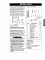
INSTALLATION REQUIREMENTS
INSTALLATION HARDWARE
Your air conditioner will install into standard double
hung windows with actual clear opening widths of
29 to 41 inches (737mm to 1041mm) (FIG. 1)
Lower sash must open sufficiently to allow a clear
vertical opening of 18 inches (457mm). Side louvers
and the rear of the air conditioner must have clear
air space to allow enough airflow through the
condenser for heat removal. The rear of the unit
must be outdoors, not inside a building or garage.
29"te4t" "_ I
I I1_ "min" Inner silll I/j -Window
III Offset
_ "_1 I_, Exterior
Interior wall "".... ° FIG. 1
ELECTRICAL SERVICE
Check your available electdcal service. The power
supply available must be the same as that shown on
the unit nameplate (found on right side of cabinet).
All models are equipped with a 3-prong service plug
to provide proper service and safe positive
grounding. Do not change plug in any way. Do not
use an adapter plug. If your present wall outlet does
not match your plug, call a qualified electrician to
make the necessary corrections.
SAVE CARTON and this OWNER'S MANUAL for
future reference. The carton is the best way to store
unit during winter or when not in use.
To avoid risk of personal injury,property damage,
or product damage due to the weight of this
device andsharp edges that maybe exposed:
• Air conditioners covered inthis manual posean
excessiveweight hazard.Two ormore people
are neededto move andinstall the unit.
To prevent injuryor strain, use proper lifting and
carrying techniques when moving unit.
• Carefully inspect locationwhere air conditioner
willbeinstalled. Be sure itwillsupport the
weight ofthe unit over an extended period of
time.
• Handleair conditioner with care. Wear
protective gloveswhenever lifting or carrying the
unit. AVOID the sharp metal fins of front and
rear coils.
Make sureair conditioner does not fall during
installation.
A B
F G
M
C D E
H I J
FIG.2
ITEM NAME OF PARTS
A SIDE CURTAIN
B SUPPORT BRACKET
C SILL BRACKET
D LOCK NUT
E SCREW: 25/64"
F SCREW: 13/16"
G SCREW: 9/16"
H M-SCREW
I CAR_RIAGE BOLT
J FOAM STRIP
K FOAM SEAL
L WINDOW LOCKING BRACKET
M DRAIN PIPE
Q'TY
2
2
2
4
11
7
5
2
2
1
1
1
1
REQUIRED TOOLS:
• Tight Fitting gloves
• Standard screwdriver
• Phillips screwdriver
• Pliers
• Sharp knife
• 3/8-inchopenend wrenchoradjustablewrench
• 1/4-inch hex socket and ratcher
• Tape measure
• Electric drill
• 1/4-inch drill bit
-5-

INSTALLATION
Pick a location which will allowyou to blow the cold air
into the area you want. Windows usedfor installation
mustbe strong enough to support the weight ofthe air
conditioner. Good installation with special attention to the
proper position ofthe unit will lessenthe chance that
servicewillbe needed.
When cooling more thanone room,installationlocationis
veryimportant.Ifairconditionerisblockedby a storm
windowframe, seestep 16 onpage8 beforebeginning to
install.To coolyourrooms,coldair mustbe blown from
the airconditionerina straight path.
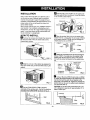
HOW TO INSTALL
I1 Remove the screws which fasten the cabinet at
the back and side of the unit. Save side screws.
Discard back screws.
_'_ Slide the unit out of the cabinet by gripping the
base pan handle and pull forward while bracing the
cabinet.
FIG. 4
_"! Cut the FOAM STRIP (ITEM J) to fit the
underside of the window sash. Peel off the backing
and attach the FOAM STRIP as shown in Fig. 5.
FIG.5
L_ Insert the side curtain (ITEM A) intothe upper guide
and lower guide of the air conditioner. Fastenthe curtains
to the unit withscrews (ITEM E).
Uppe
./ FIG.6
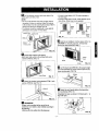
_-"'_ Open the window. Mark a line on the center of the
windowinner sill. Loosely attach the sillbracket (ITEM C)
to the support bracket (ITEM B) using the carriage bolt
(ITEM I)and the lock nut (ITEM D).
ITEMC--
ITEM I
r_ Attach the sill bracket to the window sill using the
screws (ITEM F). Carefully place the cabinet on the
window inner sill and align the center of the cabinet
front with the center line marked on the window inner
sill.
Cabinet--
trackhole ,Outer
windowsill
Carriagebolt
andlocknut Sillbracket FIG. 8
D Using an M-screw (ITEM H) and a lock nut (ITEM
D), attach the support bracket to the cabinet track hole.
Use the first track hole after the sill bracket on the
outer edge of the window sill. Tighten the carriage bolt
and the lock nut. Be sure the cabinet slants downward
1/4" from level (FIG. 9).
CAUTION: Do not drill a hole in the bottom pan. The
unit is designed to operate with approximately 1/2" of
water in bottom pan.
INDOOR
Lower guide
\
_, _ OUTDOOR FIG. 9

_] Pull the bottom window sash down behind the
upper guide until they meet.
NOTE:
• Do not pull the window sash down so tightly that the
movement of sliders is restricted. Attach the cabinet
to the window inner sill by driving the screws (ITEM F)
through the cabinet into window inner sill.
• The cabinet should be installed with a very slight tilt
downward to the outside 1/4" from level.
Windows ash
\ITEM F
FIG. 10
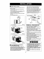
_ Expand side curtains to fill opening.
Attach each side curtain to the window sash using
2 screws (ITEM G). (FIG. 11)
ITEM G
FIG. 11
i[i] Attach the window locking bracket (ITEM L) with
a screw (ITEM G), See FIG. 12.
ITEM G
FIG. 12
Ill DRAINAGE
A drain hole is provided at the rear of the air
conditioner unit. Select a drain method accordingto
the following.
• Remove the hole rubber from the base-pan.
• Connect a drain elbow of 9/16" inside diameter to
the drain pipe.
• Connect a drain hose of 9/16" inside diameter to the
drain elbow. (Drain hose is not supplied.)
_l/ Drain ()
I_L I/pipe
Dra ni/ni_
elbow elbow
FIG. 13 hose
[]Slide the air conditionerintothe cabinet. (FIG. 14)
CAUTION: For security purposes, reinstall side
screws that were removed in step 1.
Power
/ Cord
Screw
Screw FIG. 14
_3J Cut the foam seal (ITEM K) to the proper length
and insert between the upper window sash and the
lower window sash. (FIG. 15)
FIG. 15
IL_J Adjust the vent handle before the decorative
front is attached. (FIG. 16)
Straighten the lever, as shown. Pull down part £ to
align with part £ .
Part _)
Pan1_) FIG. 16
-7-

[] FRONT INSTALLATION
Install the front grille (packed separately) onto the
cabinet as fellows:
• Hook upper tabs of front grille into slots on the
cabinet top. (FIG. 17)
• Push front grille's tips toward the cabinet in order
to snap side tabs into the cabinet. (FIG. 17)
• Open the inlet grille. (FIG. 18)
• Install the screw (ITEM E) through the front grille.
(FIG. 18)
• Close inlet grille. (FIG. 19)
IOOOII IN
1000u uo
Front Installation
FIG. 17
Frontlnstallation FIG. 18
Front Installation FIG. 19
]IF AIR CONDITIONER IS BLOCKED BY
STORM WINDOW FRAME
• If storm window presents interference, fasten a 2"
wide wood strip to the inner window sill across the full
width of the sill. The wood stdp should be thick
enough to raise the height of the windowsillso that
the unit can be installed without interference from the
the stormwindow frame. See FIG. 20.
Top of wood strip should be approximately 3/4"
higher than the storm window frame to help
condensation to drain properly to the outside.
• Install a second wood strip (approximately 6" long by
1_/2"wide and same thickness as first strip) in the
center of the outer sill flush against the back of the
inner sill. Screw the L brackets into this strip.
To support the lower guide, screw an "L" bracket (not
supplied) into this strip as shown in FIG. 20.
1 1/2" min.
WOOD STRIP MOUNTED (38mrn)
ON TOP OF INNER SILL _ _ 3/4"
.... RANCE _
_TORM
// WINDOW
NLLo
FIG. 20
REMOVAL FROM WINDOW
•Turn off andunplug the air conditioner.
• Remove the front grille. See HOWTO REMOVETHE
FRONT GRILLE. Refer to page 12.
• Unscrew the side screws that you installed in Step 12.
• Slidethe air conditioner out of the cabinet.
BE CAREFUL NOT TO DROP IT.Hold onto it firmly the
whole way sliding it out.Once removed, set it safetyout
ofthe way.
• Remove the L bracket from window frame andthe sash
sealfrom between the windows.
• Unscrew theside curtains from the window frame. Fold
them back to the sidesof the cabinet.
• Remove screwsattaching cabinet to inner sill.Be careful
not to let cabinetfall once screws are removed.
• Remove cabinet from window opening.
• Place air conditioner into cabinet. Reinstall side screws
andFront Grille.
• Place unit and all assembly hardware in air conditioner
shipping carton, and store in clean, dry place.
• Air conditioners coveredin this manual pose an
excessiveweight hazard.Two or more people
are neededto move and install the unit.
To prevent injury or strain, use proper liftingand
carrying techniques when movingunit.
• When handling the air conditioner, becareful to
avoid cutsfrom sharp metal fins on front and
rear coils.
• Make sure air conditioner does notfall during
removal.
-8-

HOW AND WHY
Your room air conditioner provides the following
functions to make hot weather living more
comfortable:
• Cools and circulates room air.
• Lowers humidity by removing excess moisture.
• Filters out summertime dust, dirt, and some
airborne impurities.
The air conditioner performs these functions by
drawing room air through a filter which traps dust
and dirt particles. The air then passes over a
cooling coil which refrigerates the air and removes
excess moisture. The same air is then returned to
the room- cooler, drier, and cleaner. Moisture
removed from the room air is carried to the outside
and evaporated.
Your air conditioner is designed to be easy to
operate and to provide plenty of cooling power.
NORMAL SOUNDS F,G.21
Aside from the regular fan motor and compressor
sounds coming from your air conditioner, you will
once in a while hear a pinging sound. This isthe
result of moisture being picked up from the air in the
room and thrown against the air conditioner's fan.
This is normal and should not be cause for concern.
Also, do not be alarmed if you hear a slight hissing
or gurgling sound coming from your air conditioner
after it is off. These are normal coolant noises.
CAPACITY AND RUNNING TIME
Proper unit size is important in deciding the desired
comfort for the area you want to cool. The proper
size isdetermined by the number of square feet in
the area to be cooled.
Whenever the heat or humidity load is above normal
the air conditioner must run longer and more often
to keep the desired temperature you have selected,
Under heavy heat load conditions the air conditioner
may need to run constantly to keep the temperature
you want.
At times using the HIGH FAN setting to circulate the
room air may make it comfortable even though you
do not have the air conditioner set to cool the air.
This will decrease your cost of use.
i an
You may hear air
movement from the
fan.
Unit Vibration
The unit may vibrate
and make noise
because of poor waft
or window
construction.
Compressor
The modern high
efficiency compressc
may have a high
pitched hum or
pulsating noise that
cycles on and off.
You may hear
droplets of water
hitting the condenser,
causing a pinging or
clicking sound.
FIG. 21
-9-

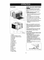
FEATURES
15 4 6
5 73 214
17 9 16 8 11 12 10 13
FIG. 22
1. Cabinet
2. Vertical Air Direction Louvers
3. Horizontal Air direction Louvers
4. Front Grille
5. Inlet Grille
6. Air Filter
7, Control Board
8. Power Cord
9. Evaporator Coil
10. Condenser
11. Compressor
12. Base Pan
13. Brace
14. Upper Guide
15. Curtain
16. Vent Control
17. Electric Heater
USING THE AIR CONDITIONER
_To reduce the risk of fire, electric
shock, or injury to persons, read the important
SAFETY instructions section before operating this
appliance
TO begin operating the air conditioner after
installation, follow these steps:
1. Plug in the air conditioner. (To prevent electrical
hazards, do not use an extension cord or an
adapter plug.)
2. Set the exhaust vent to the CLOSE position.
3. Set the TEMP Control to the coolest setting.
4. Set the MODE Control at the highest COOL level.
5. Adjust the louvers for comfortable air flow.
6. Once the room has cooled, adjust the TEMP and
MODE control to the setting you find most
comfortable.
NOTE : If the air conditioner is turned off, wait 3
minutes before restarting. This allows pressure
inside the compressor to equalize. Failure to wait 3
minutes before restarting may cause inefficient
operation.
If you move the TEMP Control to a warmer, then
immediately back to a cooler setting, the unit will
shut off. Wait 3 minutes before restarting.
VENT CONTROL
The Vent Control allows the air conditioner to either
recirculate inside air (CLOSE) or exhaust air to the
outside (OPEN). (FIG. 23)
• The CLOSE position is used when maximum
cooling is desired. It may also be used for air
recirculation without cooling when the air
conditioner is set in the FAN position.
• The OPEN position removes stale air from the
room and exhausts it to the outside. Fresh air is
drawn intothe room through your home's normal
air passages.
• The OPEN or CLOSE position can be used with
any fan selection.
FIG. 23
-10-

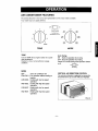
AIR CONDITIONER FEATURES
The controls featured inthis manualare representative of the manymodels available.
Your model maylookslightly different.
3
2
5
4
O. On
s Auto Swing
Turnoff AutoSwing
7 When0peralion Switch isoff
9
COOLER
OFF
FAN FAN
ONLY ONLY
LOW I__H_I LOW
NEAT COOL
HI GH
HEAT COOL
TEMP MODE
TEMP
Turn the TEMP dial to a higher number for a cooler
room temperature.
Position 5 or 6 is a normal setting for average
conditions.
MODE
OFF :Turns air conditioner off.
FAN ONLY : Fan operation without cooling or
heating.
LOWCOOL : Cooling with low fan speed
operation.
HIGHCOOL : Cooling with high fan speed
operation.
LOWHEAT : Heating with low fan speed
operation.
HIGHHEAT : Heating with high fan speed
operation.
Auto Swing
ON :Starts the operation of air swing.
OFF : Stops the operation of air swing.
Pleaseturn off Auto Swing when Operation Switch
is off.
o.LEZloo
Auto Swing
VERTICAL AIR DIRECTION CONTROL
The vertical air airection isadjusted by moving the
horizontal louvers up or down with your fingertips.
-11 -

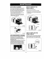
AIR FILTER CLEANING
The Air Filter wNI become dirty as it removes dust
from the inside air. It should be washed at least
every 2 weeks. If the Air Filter remains full of dust,
the air flow will decrease and the cooling capacity
will be reduced, possibly damaging the unit.
• Pull the inlet grille forward, grasping both tabs,
then pull out the air filter. (FIG. 25)
• Wash the Air Filter under the faucet with warm
water. Be sure to shake off all the water before
replacing the filter. (FIG. 26)
FIG. 25
FIG. 26
AIR CONDITIONER CLEANING
Clean the front grille and inlet grille by wiping with a
cloth dampened in a mild detergent solution.
The cabinet may be washed with mild soap or
detergent and lukewarm water, then polished with
liquid appliance wax.
To ensure continued peak efficiency, the condenser
coils (outdoor side of unit) should be checked
periodically and cleaned if they become clogged
with soot or dirt from the atmosphere. Brush or
vacuum exterior coils to remove debris from fins.
FIG. 27
HOW TO REMOVE THE
FRONT GRILLE
• Open the inlet grille downward.
• Remove the screw securing the Front Grille.
• Push the grille up from the bottom and pull the top
of the grille away from the case to lift the top tabs
out of their slots.
InletGrille
I_ i _ FrontGrille
HOW TO REPLACE THE
FRONT GRILLE
Attach the front grille to the cabinet by inserting the
tabs on the grille into the slots on the front of the
cabinet. Push the grille in until it snaps into place.
FIG. 29
-12-

BEFORE CALLING FOR SERVICE
Check the following list to be sure a service call is really necessary. A quick reference to this manual may
help you avoid an unneeded service call.
THE AIR CONDITIONER WILL NOT OPERATE
Check if... Then...
Wall plug disconnected.
House fuse blown or circuit breakertripped.
MODE selectoris OFF position.
Unit was turned offand then on tooquickly.
TEMP Controlset warmerthan room temperature.
Push plugfirmly intowalloutlet.
Replacefuse withtime delaytype or reset circuit breaker.
Tum MODE selectorto the desiredCOOL setting.
Tum unit offand wait3 minutes before restarting.
Turn TEMP Control clockwise toa cooler setting (higher number).
AIR FROM UNIT DOES NOT FEEL COLD ENOUGH.
Check if... Then...
MODE selector le LOW COOL position.
TEMP Controlset too warm (lower number).
Room temperature below 70°F (21°C),
Temperature sensing tubetouching evaporator coil,
locatedbehind front gdite.
Turn selector to HIGH COOL position
Turn TEMP Control clockwisetoa cooler setting.
Cooling may not occur until roomtemperature nsesabove 70°F (21°C).
Straighten tube away from evaporator colt.
Air filter may bedirty.
TEMP Control set toocold fornight-time cooling.
THE AIR CONDITIONER COOLING, BUT ROOM IS TOO WARM - ICE FORMING ON COOLING COIL BEHIND FRONT GRILLE.
Check if... Then...
Outdoor temperaturebelow 70°F (21°C). To defrostthe coil, setselector to FANposition. Then, tum TEMP control
counterclockwise to a warmersetting.
Clean rifler.Refer to Maintenance section of owner's manual. To defrost,
set selector to FANposition.
Todefrsettheceil,setselectortoaFANpseition.]Yten,settheMODE
controlatFANpos_ionor"HighCOOl"withtheTEMPcontroltoawarmerposition.
THEAIRCONDnlONERCOOLING,BUTROOMISTOOWARM.
Check if...
Dirty airfilter- air restricted.
TEMP Control set too warm.
Front of unit is blocked bydrapes, blinds, furniture,
etc, Air distdbutlen is restricted.
Doors,windows, registers, etc. open. Cold air escapes.
Unit recentlytumed on in hot room.
Clean air filter. Referto Maintenancesection ofowner's manual.
Tum TEMP controlclockwise to acooler setting (highernumber).
Clear blockage in front ofunit.
Closedoors,windows,registers,etc.
Allowadd_ timetoremovestoredheatfromwalls,ceiling,floor,andfurniture.
THE AIR CONDITIONER TURNS ON AND OFF RAPIDLY.
Check if... Then...
I Outside temperature is extremely hot. I SetMODEonHIaHspeedtobnngairpastcoolingceitsfaster. I
NOISE WHEN UNIT IS COOLING.
Check if... Then...
I Sound offan h_ng water- fromthe moistura rem_.,als,/stem,
Windowvibration - poor installetion. I This isnormalwhen humidflyishigh.Closedeors, windows, andragisters.
I
Refer to installationinstmcflons orcheckwith it',staller. I
l
WATER DRIPPING INSIDE ROOM WHEN UNIT IS COOLING.
Check if... Then...
I The airconditioner isimproperlyinstalled. I Tilt airconditioner slightlytothe outsideto allow waterdrainage. Referto
I
installationinstructions or checkwith installer. I
i I
m
WATER DRIPPING OUTSIDE WHEN UNIT IS COOLING.
Check If... Then...
I The unitisremovinglarge quantities of moisture
! This isnormalduringexcessively humiddays. J
fromhumid room.
I
-13-

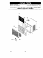
Room Air Conditioner To order Parts call Toll Free
Model No. 580.72187200 1-800-4-MY-HOME®(1-800-469-4663)
CAUTION: Use the Kenmore part number on all orders, not the illustration number.
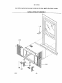
CABINET & FRONT GRILLE ASSEMBLY
3-A
7-A_ 4-A
12/01 - 14 -

580.72187200
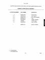
CAUTION: Use the Kenmore part number on all orders, not the illustration number.
CABINET & FRONT GRILLE ASSEMBLY
ILLUSTRATION NUMBER PART NUMBER
DESCRIPTION
1 -A 3530AR1182A FRONT GRILLE
2 - A 3530AR1531A INLET GRILLE
3 - A 5230AR1327A AIR FILTER ASSEMBLY
4 - A 5990AR2972C VANE
5 - A 3091AR6057C CABINET ASSEMBLY
6 - A 2H00858E UPPER GUIDE
7 - A 3850A20423N LABEL, ENERGY
3828A20145Y
MANUAL OWNER'S
# = Functional Parts
* = Non-illustrated Parts
- 15 - 12/01

580,72187200
CAUTION: Use the Kenmore part number on all orders, no_._Jtthe illustration number.
CONTROL BOX ASSEMBLY
10-B 2-B 1-B 16-B 4-B
8-B
7-B
6-B
9-B
5*B
@
13-B
11-t3
- 3-B
15-B
12/01 -16-

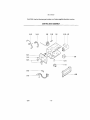
580.72187200
CAUTION: Use the Kenmore part number on all orders, not the illustration number.
CONTROL BOX ASSEMBLY
ILLUSTRATION NUMBER PART NUMBER
DESCRIPTION
1 - B # 4994AR1587A CONTROL BOX
2 - B 2H01127B THERMOSTAT
3 - B 2H00598F ROTARY SWITCH
4 - B 6120AR2359E SH CAPACITOR
5 - B # 2H00677U POWER CORD ASSEMBLY
6 - B 4941AR7134C KNOB ASS'Y
7 - B 2H01316C ROCKER SWITCH
8 - B 3721A20058G PANEL, CONTROL
9 - B 4004AR4357A CLIP CORD
10 - B 6631AR2687P CONNECTOR ASSEMBLY
11 - B 2H01102A SYNCHRONOUS MOTOR
12 - B 4520AR4386A LINK
13 - B 4520AR4339A CAM
14 - B 6877A20002A CONNECTOR ASSEMBLY
15 - B 3551A30015A COVER, CONTROL BOX
16- B 4H00442F CLAMP, CAPACITOR
# = Functional Parts
* = Non-illustrated Parts
- 17 - 12/01

580.72187200
CAUTIQN: Use the Kenmore part number on all orders, not the illustration number.
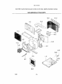
AIR HANDLING & CYCLE PARTS
15-C 21-C
14-C
4-C
13-C
16-C
11-C
22-C
12/01 - 18 -

580.72187200
CAUTION: Use the Kenmore part number on all orders, not the illustration number.
AIR HANDLING & CYCLE PARTS
ILLUSTRATION NUMBER PART NUMBER DESCRIPTION
1 - C 3041A30002K BASE PAN WELD ASSEMBLY
2 - C 5238AR1584B AIR GUIDE
3 - C 3072AR1583A SCROLL
4 - C 4790AR1558A BARRIER
5 - C 4900AR7265A DAMPER
6 - C 4960AR1596A MOTOR MOUNT
7 - C # 4681AR6033K MOTOR ASSEMBLY
8 - C 3040AR6160A INSULATION, EPS
9 - C # 5834AR1599B BLOWER
10- C # 5900AR1508A FAN
11 - C 3H02932C CLAMP SPRING
12 - C 4998AR1597A SHROUD
13 - C 4800AR7272A BRACE
14-C # 5421A20059F EVAPORATOR ASSEMBLY
15-C # 5403A20004F CONDENSER ASSEMBLY
16 - C 3550AR6173A COVER, SHROUD
17 - C 4H01029F WASHER RUBBER
18 - C 3H02773A DRAIN PIPE
19 - C 4H00261A PIPE ELBOW
20 - C 4H02023A HOLE RUBBER
21 - C 3530A20002B GRILLE, REAR
22 - C 5301A30001 B ELECTRICHEATER ASSEMBLY
# = Functional Parts
* = Non-illustrated Parts
- 19 - 12/01

580.72187200
CAUTION: Use the Kenmore part number on all orders, not the illustration number.
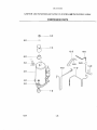
COMPRESSOR PARTS
9-D
8-D Q
6-D
2-D
4-D
3-D
©
1-D
12-D 15-D
0-D 11-D
12/01 - 20 -

580.72187200
CAUTION: Use the Kenmore part number on all orders, not the illustration number.
COMPRESSOR PARTS
ILLUSTRATION NUMBER PART NUMBER DESCRIPTION
1- D 4H00982C
2- D # 5416A20003J
3-D 4H01811C
4- D 1NHA0801206
5- D 6877A20002B
6-D 4986U-L001D
7- D 3550U-L002C
8- D 4H01058A
9- D 4H00947A
10- D 5211A30066K
11- D 5211A20204C
12-D 5211A20433B
13- D 5211A20434B
14- D 5211AR7059W
15- D 5211A20020P
16- D 5851A30001F
ANTI-VIBRATION BUSHING
COMPRESSOR ASSEMBLY
BRACKET, WASHER
HEXAGON NUTS
CONNECTOR ASSEMBLY
GASKET
TERMINAL COVER
GASKET NUT
TERMINAL COVER NUT
TUBE ASSEMBLY, DISCHARGE
TUBE ASSEMBLY SUCTION
TUBE ASSEMBLY, EVA IN
TUBE ASSEMBLY, EVA IN
TUBE CONNECTION,COND.OUT
TUBE, CAPILLARY
DRIER, ASSEMBLY
# = Functional Parts
* = Non-illustrated Parts
- 21 - 12/01

580.72187200
CAUTION: Use the Kenmore part number on all orders, not the illustration number.
INSTALLATION KIT ASSEMBLY
12/01 - 22 -

580.72187200
CAUTION: Use the Kenmore part number on all orders, not the illustration number.
INSTALLATION KIT ASSEMBLY
ILLUSTRATION NUMBER PART NUMBER
DESCRIPTION
1 - E 4H01785B L BRACKET
2 - E 4959AR3402E CURTAIN ASSEMBLY
3 - E 4959AR3402F CURTAIN ASSEMBLY
4 - E 3H01479D SUPPORT BRACKET
5 - E 3H01395C SILL BRACKET
6 - E 4H01516A LOCK NUT
7 - E 4H01483A CARRIAGE BOLT
8 - E 4H01482A M-SCREW
# = Functional Parts
* = Non-illustrated Parts
- 23 - 12/01

INDICE DE MATERIAS ............................. 24
GARANT[A ................................................ 24
SEGURIDAD .............................................. 25
Importantesinstruccionesdeseguridad .....25
REQUERIMIENTOS ELI_CTRICOS .........26
INSTALACI(_N ........................................... 27
Requerimientos para instalaci6n .......... 27
Installaci6n ............................................ 28
Cbmo instalarlo ..................................... 28
La eliminaci6n de la ventana ................. 30
OPERACI(_N .............................................. 31
C6mo y por qu_ ..................................... 31
Sonidos normales .................................. 31
Capacidad y tiempo de funcionamiento ...31
Caracteristicas ..................................... 32
Uso del equipo de aire acondicionado -.32
Despliegue ............................................ 33
MANTENIMIENTO .................................... 34
Limpieza del filtro del aire ...................... 34
Limpiezadel equipode aireacondicionado....34
C6mo a reemplaza el grille anterior ......34
CORRECCION DE FALLAS ...................... 35
AntesdeUamarparaServicio...................... 35
LISTA DE PARTES ............................. 14~23
PARA PEDIR SERVIClO ....Cubierta Trasera
GARANTJA DE UN ANO POR EL
EQUIPO DE AIRE ACONDICIONADO
DE HABITACION
Durante unafiocompleto a partir de lafecha de
compra, si este equipode aire acondicionadorecibe
mantenimiento y se utiliza parael enfriamiento
normal de habitaci6nsegen las instrucciones
indicadas eneste manual del propietario, Sears
reparar&gratuitamente este equipo de aire
acondicionado, si tiene alg=3ndefecto en materiales
o fabricacibn.
GARANTIA TOTAL DE CINCO ANOS
POR E.LSISTEMA DE REFRIGERACI(_N
HERMETICAMENTE SELLADO
Durante cinco afios a partir de la fecha de compra,
si este equipo de aire acondicionado recibe
mantenimiento y se utiliza para et enfriamiento
normal de habitaci6n segen las instrucciones
indicadas en este manual del propietario, Sears
reparar_ gratuitamente el sistema de refrigeracibn
herm_ticamente sellado (que consiste en el agente
refrigerante, los tubos de conexibn y el compresor),
si tiene algen defecto en materiales o fabricaci6n.
EL SERVIClO DE GARANT[A EST'. A SU
DISPOSICI6N CON S6LO PONERSE EN
CONTACTO EL CENTRO DE SEARS AL
1-800-4-MY-HOME ®
La proteccion de garantia cubre unicamente a
los equipos de aire acondicionado usados para
uso domestico y no para use comercial.
Esta garantia s61otiene validez mientras el
producto se este usando en los Estados
Unidos.
Esta garantia le da derechos legales
especfficos y usted puede tener otros
derechos que varian de estado en estado.
Sears, Roebuck and Co., D/817WA,
Hoffman Estates, IL 60179 U.S.A.
- 24-

IMPORTANTES INSTRUCCIONES DE SEGURIDAD
Las siguientes instrucciones de seguridad le indicar_n c6mo usar su equipo de sire acondicionado de
habitaci6n para evitar dafios para usted mismo y para su EQUIPO DE AIRE ACONDICIONADO.
PeR SU SEGURIDAD
No almacene ni use gasolina u otros vapores y
liquidos inflamables cerca de 6ste o cuaiquier otro
electrodomestico. Lea las etiquetas de los
productos para ver si contienen adverlencias sobre
el caracter inflamable de los mismes y otras
advedencias.
PARA PREVENIR ACCIDENTES
Para reducir el riesgo de incendios, descargas
electricas o lesiones personales al usar su equipo
de aire acondicionado, tome las precauciones
basicas, entre las que estan las siguientes:
• Asegurese de que la alimentaci6n electrica sea la
apropiada pars el modelo que usted ha elegido.
• Si el equipo de aire acondicionade debe instalarse
en una ventana, a usted probablemente le
conviene limpiar primero ambos lades del vidrio.
Si la ventana es del tipo de tres paneles con un
panel incluido de pantalla, le conviene sacar la
ventana completamente antes de la instalaci6n.
• Asegerese de que el equipo de aire
acondicionado ha side instalado correctamente y
con seguridad segen se serials en las
instrucciones separadas de instalaci6n que vienen
en este manual. Conserve este manual y las
instrucciones de instalaci6n para usarlos
posiblemente en el future al sacar o velvet a
instalar esta unidad.
• Utilice guantes al manejar el equipo de aire
acondicionado, tenga cuidado pars evitar cortadas
con las afiladas aletas metalicas que se hallan en
los serpentines frontales y posteriores.
INFORMACION ELECTRICA
En la plaea de serie del fabricante se indica cuaf es
la capacidad electdcanominalcompletade sunuevo
equipo de aireacondicionade para habitaci6n.Consulte
esta placacuando vaya avedficar los requedmientos
el6ct_k:os.
• Aseg_rese de queel equipo de aireacondicionado
tenga unaconexi6n corrects a tierra. Para reduciral
mfnimo los desgos de descargas el6ctdcase incendio,
es importante conectar el equipo correctamente atierra.
Elcord6n de alimentaci6nel6ctdca esta equipado con
un enchufede tres espigascon conexi6n a tierrapara
protegede contra desgos de descargas el6ctdcas.
• Su equipo de aireacondicionado debe enchufarseen
unatoma de corriente de paredque tenga unaconexi6n
correcta atierra.Si latoms de cordente de paredque
usted piensausar no est&conectada correctamente a
tierra o no esta protegidacon unfusible de acck_
relardade ocon un interrupterde circuito, haga que un
electricista calificadele instale latoma de cordente de
pareden forma cor_-_cta.
• No ponga a funcionar el equipo de aire acondicionade
con una cubiertaprotectora extedorenc_ma.Esto podn'a
ocasionar defies mecdnicos dentro delaire
acondicionado.
• No use un cable de extensi6n nl un enchufe
adaptador.
_ Evitelos peligrosde incendiosy
descargasei6ctdcas.No useun cabledeextensi6nni un
enchufeadaptador.Noelimineningunade lasespigas
delenchufedelcord6nde alimentaci6nel6ctdca.
Tomade corriente
deparedcon En ninguna
conexiona tierra, circunstancia corte,
extraiga o intente
eliminar Isespiga de
conexi6n a tierra de este
enchufe.
Cord6n de alimentaci6n el6ctrica con
enchufe de tres espigascon
conexi6n a tierra.
IDEAS PARA AHORRAR ENERG|A
• La capacidad del equipo de aire acondicionado
debe corresponder al tamafio de la habitaci6n
para el funcionamiento eficiente y satisfactorio del
equipo.
• Instale el equipo de sire acondicionado de
habitaci6n en el lade sombreado de su hogar, Una
ventana orientada hacia el norte es la mejor
porque tiene sombra la mayor paste del dfa,
• No bloquee el flujo de sire hacia el interiorcon
persianas, cortinas o muebles; o la parle de
afuera con arbuetos, paredes u otrae
construcciones.
• Cierre el regulador de tire de la chimenea, las
rejillas de calefacci6n del pisoy la pared, de tal
mode que el sire fr(o no se escape ni per la
chimenea ni per los conductos.
• Mantenga las persianas y las cortinas de otras
ventanas cerradas durante la parle mds soleada
del dia.
• Limpie el filtro del sire come se recomienda en la
secci6n "MANTENIMIENTO" de este manual.
• El aislamiento correeto y las juntas herm6ticas en
puertas y ventanas en su hogar le ayudardn a
mantener el aire caliente afuera y el sire fr(o
adentro.
• AI darle sombra extemamente a la casa con
drboles, plantas o toldos ayudard a reducir la
carga de trabajo del equipo de aire acondicionado.
• Opere los aparatos que producen calor come, per
ejemplo, hornos, lavadoras, secadoras y
lavaplatoe durante la parte mds frfa del dfa.
- 25 -

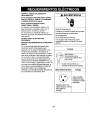
RESPETE TODOS LOS C(_DIGOS Y
REGLAMENTOS.
BAJO NINGUNA CIRCUNSTANCIA CORTE,
QUITE O EVITE EL USO DE LA CONEXI(_N
A TIERRA DE ESTA CLAVIJA.
ESTE APARATO NECESITA SER
CONECTADO A TIERRA.
Se requiere una alimentaci6n electrica CA,
adecuadamente conectada a tierra con un
fusible de 20 A, de 60 Hz y de 250 V.
Se recomienda un fusible de retardo o un
disyuntor de circuito que alimente solamente a
este aparato.
NO USE CABLE ELI_CTRICO DE
EXTENSIC)N.
MI_TODO RECOMENDADO DE CONEXION A
TIERRA
Por su propia seguridad este aparato debe
conectarse a tierra. Este aparato viene
equipado con un cable de alimentaci6n y una
clavija de tres terminales. Para reducir al
maximo el peligro de choque el_ctrico, el cable
debe estar conectado a una conexi6n de pared
con conexi6n a tierra, y esta conexi6n debe
hacerse de acuerdo con la Oltima edici6n del
C6digo El_ctrico Nacional (ANSI/NFPA 70), asf
como con los c6digos y reglamentos locales. Si
no existe una conexi6n de pared adecuada, el
cliente tiene la responsabilidad y la obligaci6n
de mandar instalar, con un electricista
calificado, una conexi6n de pared adecuada de
tres terminales con conexi6n a tierra.
ADVERTENCIA
Peligrode choqueel_ctrico
Conecteen unaconexionde paredde 3 terminales
Noquite laterminalde conexi6natierra
Nouseadaptadores
Nousecableelectdcodeextensi6n
Si nose siguenestasinstrucciones,puede
ocasionsrselamuerte,unincendioo unchoque
electnco.
Enchufe
_ / circunstanciaBaj°Ninguna
coneo
_- _ remueva el salida de tierra
del enchufeCord6n tomacorriente con
enchufe de tierra de tres salidas.
Utilicerecibicloresdepared Energfa
Estdndar 250V, tres
cables receptor a tierra
20A, 250V AC
nominal.
Utilice 20 AMP,
fusible de tiempo
retardado o fusibl_
Interruptor.
- 26 -

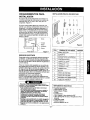
REQUERIMIENTOS PARA
INSTALACION
Su equipo de aire acondicionado se instalara en
ventanas estandar de doble panel con anchos de
abertura libre de 737 mm a 1041 mm (29 a 41
pulgadas). (Figura 1)
El marco inferior debe abrirse Io suficiente para
permitir una abertura vertical libre de 457 mm (18
pulgadas). Las rejillas desviadoras laterales y la
parte posterior del equipo de aire acondicionado
deben tener un espacio libre de sire para permitir
suficiente flujo de airea trav6s del condensador
para asi eliminar el calor. La parte posterior de la
unidad debe quedar al aire fibre, no dentro de un
edificio o garaje.
__l I Bands
=,,o,,4/
18"min. . Ventana
II, "e0,s,l.lS
II Rebajo
_'_-' Antepecho
I? E'teri°r
Paredinterior'-----" "
Figura 1
SERVICIO ELECTRICO
Compruebe cual es la alimentaci6n el6ctrica que Ilega a
sudomicilio. La alimentaci6n electrica disponible debe
ser la misma quese muestra en la placa delfabricante de
la unidad (que se halla en el lado derecho delgabinete de
corriente altema).
Todos los modelosestan equipados con un enchufe de
Ires espigas para suministrarun servicio correcto y una
conexi6n atierra segura y positiva. No cambie el enchufe
de ninguna forma. No use unenchufe adaptador. Si su
toms de corriente de paredactual no puede usarse con el
enchufe del equipo, Ilameaun electricista calificado para
que efect0e las correcciones necesarias.
CONSERVE LA CAJAy este MANUAL DEL
PROPIETARIO para que le sirra como referencia en el
futuro. La caja es la mejor manera de conservar la unidad
durante el invierno o cuando no est6 en uso.
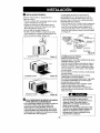
INSTALACI(_N PIEZAS DE MONTAJE
A B
F G
L M
C D E
H I J K
Figura 2
iTEM NOMBRE DE LAS PIEZAS
A PANEL DE GUiA
B SOPORTE
C SOPORTE DE ANTEPECHO
D CONTRATUERCA
E TORNILLO: 25/64"
F TORNILLO: 13/18"
G TORNILLO: 9/16"
H TORNILLO M
I BUL(_N
J ClNTA DE ESPUMA
K ClNTA DE ESPUMA
L SOPORTE DE CERRADURA
M TUBO DE DRENAJE
CANTIDAD
2
2
2
4
11
7
5
2
2
1
1
1
1
Paraevitarel riesgodeles_onespersonales,danosasu
propiedadod_ alproductodebidoalpesodeesteequipe
ylos losaqueseranexpuestos:
• Elaireacondicionadedelque sehabtaenestemanuel
afirmapeligrodepesoexsesivo.
Dqsomaspersonasse requiemparsmovereinstelarla
unidad.Paraevitarheridasoagotamlento,usetecnicas
apropiadesparslevntary moverlaunidad.
•Cuidadosarnenteinspecdoneel lugardondeelaire
asondidonadoserapuesto.Aseguresequeetlugar
sostengaelpesodelaunidadso,reunperlodoOetiempe
prolongado.
•Mantengasuaireacondicionadoconcuidedo.Useguantes
protectorescuandolevanteomuevalaueldad.EVITElas
eletasfilosasdemetalenelserpentindelanteroy deatras.
• _'g. ur6,sequeelelreanondielonadonosecelgadurantela
=nsta]aelon.
HERRAMIENTASREQUERIDAS
• Guantes apretados
• Destornillador normal
• Destornillador Phillips
• Pinsas
• Cuchillo filoso
• Llave inglesa o Ilave abierta de 3/8"
• Llave hexagonal de cubo y trinquete de 1/4 de
pulgada
• Cinta pars medir
• Taladro eleetrico
• Broca de taladro de 1/4"
- 27 -

INSTALACION
Escolaunlugarque lepermitaIlevarel airefrio alareaque
desea.Lasventanasquese usenparala instalaciondeben
tenerla resistenciasuficienteparasoportarelpesodel equipo
deaireacondicionado.Unabuenainstalacionconatenci6n
especialala correctaposicionde la unidaddisminuir_la
probabilidadde queseanecesarioefectuarreparaciones.
Cuandosedeseaenfriarmasde unahabitacion,la
instalaciones muy importantesi etaireacondicionadoesta
bloquedopor unmarcode la cnntraventanayeael paso16en
la pagina8antesdecomenzarla instalacion.Paraenfriarsus
habitaciones,elairefrio debedesplazarsedesdeelequipode
aireacondicionadoen unatrayectoriarecta.
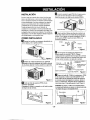
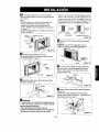
COMO INSTALARLO
liJ Saque Ins tornillos que aseguran el gabinete en
ambos lados yen la parte posterior.
Figura 3
IP'_ Deslice la unidad sacandola de su gabinete
agarrando el asa del recipiente de la base y tirando
de ella haeia delante mientras sostiene el gabinete.
Flgura 4
I_Jl Corte la cinta de espuma (ITEM J) a la
extension apropiada.
Despegue el refuerzo y peguelo en el lado de abajo
del marco de la ventana.
Figure 5
L_ InsedeIns panelesde guia(iTEMA) en la goia superior
y lasguias demarco delequipodeaire acondicionado.
Sujetelascortinas enla unidadcon Instomillos (iTEME)
iTEM E
Guia mas baja
IL_ Abra laventana. MarqueunaIlnea en el centro de la
repisade la ventanaentre Ins moldesde tope lateralde la
ventana. Fijesin apretar el soporte de antepecho(ITEMC)
al otro soporte (iTEM B) usandoel bul6n (iTEM I) y la
contratuerca(iTEM D).
iTEMC -_ _
,TEM, ql
IlULI iTEMD
Figura 7
r_Fije el soporte de antepecho alantepecho a la
ventana usando Ins tornillos (iTEM F). Coloque
cuidadosamente el gabinete sobre la repisa de la ventana
y alinee la marca del centro en la parle frontal inferior con
la Ifnea central marcadaen la repisa de la ventana.
iTEM B
Tornillo para metales y
j_contratuerca
Borde exterior del
_antepecho de la
ventarla
Bul6n y contratuerca _j (iTEM F)
Soporte de antepecho Figura 8
_'-_ Usandoel tomilloM (iTEM H)y la contratuerca (iTEM
D), fije el soporte al orificio decarril delgabinete. Useel
primerodficio de carril despu_sdel soportede antepeeho
en elborde exteriordel antepechodeventana.Apriete el
bulon y la contratuerca.Aseg_resede que el gabinetese
inclinehacia fuera1/4 de gotausando el nivel. (Figura9)
CUIDADO:No perfore un orificio enel recipienteinferior.
Launidad est'. disefiada para operar conaproximadamente
1/2 pulgadade aguaen el recipienteinferior.
- 28 -

ILr_ Tire del marco inferior de la ventana hacia abajo
detras de la guia superior hasta que se encuentre la guia
con el marco.
NOTA:
• No tire del marco de laventana tan hacia abajo que
restrinjael movimiento de las correderas. Fijeel
gabinete a la repisa de la ventana atornillando los
tornillos (ITEM F) a trav6s del gabinete en la repisa de
la ventana.
• El gabinete debe instalarse 1/4 de gota de el nivel, hecia
abajo y hacia fuera.
MarCOde
Encuadre
codina
iTEMF Figura 10
I_]1 Extienda el panel hasta Uenar el hueco,
Fije cada panel gufa en el marco de la ventana usando
dos torniUes ({TEM G). (Figura 11)
iTEM G
'Guide Figara 11
i'[i] Se debe instalar el asa antes de fijar el frente
decorative. (Figura 12)
.iTEM G
Figura 12
i_ DREANJE
En _ part_posteriorde {aunidadde aim acondicionadohay
un orificiode drenaje. Selecoione un mdtodo de drenaje
segL_nlassiguientesinstrucoiones:
•Saquedel recipientedebase lagomadel orificJo.
•Conecteuna manguerade drenajede 9/16"de p_._gadede
diametmintemoal tubede drenajeoomose muestra.
• Conecteun codede tube de 9/16"de pulgadade diametro
interne al tube de drenaje, conecte seguidamente una
manguera de drenaje de 9/16" de pulgada de diametro
ir_temoal code dettubecomese muestra.(Etequipodeaire
acondicionadenovieeecon unamangueradedrenaje.)
t= r4
drenaje i I _renaje
Tube de i, ,ubo de
[_ Manguera _'_ Code _
de drenaje Manguera de drenaje
Figura 13
i_l Deslice el chasis hacia el interior del gabinete.
(Figura 14)
CUIDABO: Con fines de seguridad, vuelva a
instalar los tornillos en los lades del gabinete.
Cordon de
Tornillo electrica
Tornillo Figura 14
i_ Corte la junta hermetica de espuma(iTEM K)
para que tenga, la Ioegitud aprepiada e insdrtela
entre el marco superior y el marco inferior de la
ventana. (Figura 15)
Figura 15
IL_ Ajuste el asa antes de fijar el frente decorative.
(Figura 15)
Enderence el kit de ventilacion come se indica,
halando hacia debajo de la parte £ Ilevandola en la
linea horizontal con la parte £ .
Parte_)
parle _)
Figura 16
- 29 -

INSTALACI(_N FRONTAL
Instale la rejilla frontal con el gabinete de la
siguiente manera:
• Tire de la rejilla frontal hacia abajo desde la parte
superior del gabinete. (Figura 17)
• Empu}e las puntas de la rejilla frontal hacia el
gabinete para inserlar las leng etas de la rejilia
dentro del gabinete. (Figura 17)
• Abra la rejilla de entrada. (Figura 18)
• Apriete el tornillo (iTEM E) a traves de la rejilla
frontal fijAndolo al recipiente de base (Figura 18)
• Cierre la rejilla de entrada. (Figura 19)
Instalacidn frontal
Figura 17
. iTEM E
Instalacidn frontal Figura 18
Instalaci6n frontal
Figura 19
_SI ELACONDICIONADORDEAIREESTABLOQUEADO
POREL MARCODELACONTRAVENTANA
• Si lacontraventanainterfiere,fijeunlist6nde madera de
2" deanchoal alf_izarinterior de laventana, que
atraviesela anchuratotaldelalf_izar.El list6nde
maderadebesar suficientemente gruesoparalevantar
la altura delalf_izarde laventana de tal manera quela
unidadpuedaser instaladasinlaintefferenciadelmarco
de la contraventana.Vea laFigura20.
La partesuperior del listen de madera debe ser
aproximadamente 3/4" mas alto queel marcode la
contraventana o el list6n de madera (fuera de lacasa)
pare que el vapor emanado de la unidad pueda drenar
adecuadamente hacia el exterior
• Instaleunsegundolist6nde madera(deaproximadamente
6" delargo y 1"de anchoy detmismogresordelprimer
listen)en el centredelalfeizarexteriorniveladoconla
parteposterior delalfeizarinterior Atornillelos soportesL
entre lafala. Esto levantarael sopode Lcomese muestra
en laFigura 20
1 1/2" rain
FRANJA DE MADERA ----,,_38mm/._p 3!4-PULG
/
MONTADA
SOBRE -_ . DE SEPARACION 1_
LA PARTE SUPERIOR _*_- *
eEL OESCANSO _._
INTERIOR VENTANA DE
_ HOJA DOBLE
ANTEPECHO
ANTEPECHO
I ERIOR
Figura 20
La EMMINACIONDE laVENTANA
• Apagueel acondicionedoraereo.
• Quiteelgrilleanterior VeaCOMOAREEMPLAZAELGRILLE
ANTERIORRefi_raseapagina34.
• Destornilleel tornillodelladequeustedinstal5enel Paso12.
• Desliceelacondicionadera_reofueradelgabineteTENGA
CUIDADOnoAla GOTA TengaenIofirmementela manera
enteraquedeslizafuera.Unavezquitado,Iopusoseguridad
fueradela manera.
• QuiteelparentesisLdelmarcodeventanayel sellodebanda
deentreelwindows
• Destornillelas_:ortinasdelladede1marcodeventana.
Doblelosapoyana losladesdelgabinete.
• Quiteeltornilloconectargabinetealalfeizalinterior.Tengacuidado
noapermiti5quegabinetefallaraunaveztornillossequitan
• Quitegabinetedeabrirdeventana.
• Coloqueelacondicionadoraereoenel gabinete.Vuelvaa
instalarlostomillosdelladey GrilleAnterior.
• Coloquelaunidadytodaferreteriade laasambleaenel
cart6na_reodelenviodelacondicionador,yen latiendaen
limpia,secaellugar.
• El aire acondicionado del que se habla en este
manual afirma peligro de peso excesivo.
Dos o mas personas se requiere para mover e
instalar la unidad. Para evitar heridas o
agotamlento, use tecnicas apropiadas para
tevntar y mover la unidad.
• AI manejar la unidad, tenga cuidado para evitar
cortarse con las alertas metalicas afiladasque
estdn en los serpentines frontal y posterior.
• Asegurese que el aire acondicionado no se
caiga durante la instalacion.
- 30-

COMO YPOR QUE
Su equipo de aire acondicionado de habitaci6n
brinda laa siguientes funciones para hacer que la
vida en climas calidos sea mas confortable:
• Enfrfa y hace circular el aire per la habitacion
• Disminuye la humedad eliminando la humedad
excesiva.
• Filtra el polvo, el suoio y algunas impurezas
transportadas en el aire del clima veraniego.
El equipo de aire acondicionado realiza estas
funciones haciendo pasar el aire del medio
ambiente a traves de un filtro que atrapa las
partfculas de polvo y sucio. El aire pasa entonces
por un serpentin de enfriamiento que refrigera el
aire y elimina el exceso de humedad. El mismo aire
regresa entonces al enfriador, secador y Umpiador
del aire del ambiente. La humedad extraida del aire
ambiente es Ilevada al exterior y evaporada.
Su aire acondicionado est,. diseSado para operar y
suministrar una enorme potenoia de enfriamiento.
SONIDOS NORMALES Figura21
Ademas de los sonidos regulares del motor del
ventilador y el compresor que salen de su equipo
de aire aeondicionado, usted escuohar& de vez en
cuando un sonido met_lico. Este sonido es
producido por la humedad que ea recogida del aire
en el ambiente y es lanzada contra el ventilador del
equipo de aire acondicionado. Esto es algo normal
que no debe ser motivo de preocupaci6n. De igual
modo, no se alarme si usted escucha un ligero
sonido de silbido o borboteo proveniente de su
equipo de aire acondicionado deapues que Io
apaga. Estos son ruidos normales del refrigerante.
CAPAClDAD Y TIEMPO DE
FUNClONAMIENTO
AI decidir cu_l debe ser la comodidad deseada para el
drea que usted quiere enfriar, es importante
determinar el tama_o correcto de la unidad. El tama_o
adecuado es determinado por el nQmero de metros
cuadrados que tiene el &rea que se desea enfriar, asf
como por la temperatura interiory exterior y por la
humedad.
Siempre que la carga termica del ventilador est_ pot
encima de Io normal, el equipo de aim acondicionado
debe funcionar mas tiempo para mantener la
temperatura deseada que usted ha seleccionado. Bajo
condiciones de una carga t_rmica muy pesada, puede
ser necesario que el equipo de aire acondicionado
funcione constantemente para mantener la
temperatura deseada.
En ocasiones, el uso de HIGH FAN para hacer circular
el aire por la habitacibn hace que el ambiente sea m&s
confortable aun cuando el equipo no est_ enfriando el
aire. Mientras m_s tiempo y con mayor frecuencia
funcione el equipo de aire acondicionado, mas
electricidad consumira y mayores ser_.n los costos de
SU use.
Ventilador
Ustedpuedeescuchar
el movimientodel aire
provenientedelventilador
Vibraciones de
la unidad
La unidad puede
vibrar y hacer ruido
debido a la deficiente
construcci6n de la
pared o la ventana.
Compresor
El moderno compresor
de gran eficiencia puede
producir un ruido agudo
de murmullo o un ruido
de pulsaci6n que
viene y se va
III
li_ Condensador
Ustedpuedeescuchar
gotasde agrJaquecaen
sobreel condensador
¢ausandoun sonido
met&licoo unsonidode
chasquido.
Figura 21
-31 -

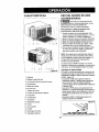
CARACTER[STICAS USO DEL EQUIPO DE AIRE
i
' i I
15 4 6 5 73214
i i
17 9 16 8 11121013
Figura 22
1. Gabinete
2. Deflector vertical de aire
3. La Direcci6n A_rea horizontal Louvers
4. Grille anterior
5. Rejilla de entrada
6. Filtro del aire
7. Tablero de control
8. Cord6n de alimentaci6n el6ctrica
9. Evaporador
10. Condensador
11. Compresor
12. Recipiente de base
13. Puntal
14. Guia superior
15. Cortina
16. Descargar el Control
17. Calentador electrico
ACONDICIONADO
_Para reducir el riesgo de incendio,
descargas electrica o lesiones personales, lea las
IMPORTANTES INSTRUCCIONES DE
SEGURIDAD antes de operar este aparato.
Para comenzar a utilizar el equipo de aire
acondicionado, siga estos pasos:
1, Enchufe el equipo de aire acondicionado,(Para
prevenir riesgos de descargas el_ctricas, no use un
cable de extensi6n ni un enchufe adaptador.)
2. Ajuste el extractor de aire en la posici6n CERRADA
3. Ajuste el control de MODE al mas alto nivel fresco.
4. Aluste el control del ventilador al m_.s alto nivel.
5. Ajuste _asrejillas desviadoras para Iograr un flujo
confortable de aire con la leng(Jeta de control.
6. Una vez que la habitaci6n se haya enfriado, ajuste
el control de temperatura TEMP a la graduaci6n
que usted considere mds confortable.
NOTA: Si se apaga el aire acondicionado, espere 3
minutos antes de volver a encenderlo. Esto permite
que se estabilice la presi6n dentro del compresor. Si
no sigue estas instrucciones, el equipo podfia
funcionar con poca eficiencia.
Si usted mueve el TEMP el control a un warmer,
entonces inmediatamente espalda a una colocacion
mds fresca, la unidad apagard. Espere 3 minutos.
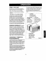
CONTROL DE VENTILACI6N
Elcontrol de ventilaci6n permite que el equipo de aire
acondicionadohaga recircularel aire en el interiorde
la habitaci6r_(CLOSE) o saque el aire hacia el exterior
(OPEN). (Figura 23)
• La posieibnCLOSE sirvecuando se desea un
enfriamientomdximo. Tambidn puede usarse para
hacer recircularel aire sinenfriar la habitaci6n
cuandoel equipode aire acondicionadose ajusta en
la posici6n FAN.
• La posici6nOPEN extrae el aire estancado de la
habitaci6ny Io expulsa hacia fuera. El aire fresco es
Ilevadohacia el interiorde la habitaci6n a trav_sde
lospasajes normalesde airo que se hallanen los
hogares.
• La posici6nOPEN o CLOSE puede usarse con
cualquierselecci6n de ventilador.
Figura 23
(TIRAR PARAABRIR I EMPUJAR PARA CERRAR)
- 32 -

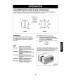
CARACTERiSTICAS DEL EQUIPODEAIRE ACONDICIONADO
Los controles que se explican en este manual son representativos de muchos modelos disponibles a la
venta en el mercado. Su modelo puede tener un aspecto ligeramente diferente.
4
2
Off [_ On
5 OFF
6 Auto
_ b
bwmg FAN.FAN
___9 _ ONLY ONLY
TurnoffAutoSwing G_
When I_pe(_tlOrl Switch L_Off
LOW LOW
HEAT COOL
HI GH
HEAT COOL
COOLER
TEMP MODE
TERMOSTATO
Gire el dial TEMP al nL_merom_ts alto para una
temperatura ambiente m_ls fresca. La posici6n 5 o 6
es una graduaci6n normal para las condiciones
promedios.
MODO
OFF :Apaga el aire acondicionado.
FAN ONLY : Permite el funcionamiento del
ventilador a baja velocidad sin enfriar
(calentar).
LOW COOL : Permite el enfdamiento con el
funcionamiento del ventilador a baja
velocidad.
HIGH COOL: Permite el enfriamiento con el
funcionarniento del ventilador a alta
velocidad.
LOW HEAT : Permite el calentamiento con el
ventilador a baja velocidad.
HIGH HEAT: Permite el calentamiento con el
ventilador a alta velocidad.
AUTOSWING (Oscilacion Automatica)
On : (Encendido) La oscilaci6n de aire es operada
mientras la perilla Operation (operaci6n) se coloca
en laposici6n Cool (enfriamiento).
Off :(Apagado) Deliene la operaci6n de la oscilaci6n
de aire.
Off.On
Auto Swing
CONTROL DE DIRECCI6N VERTICAL DEL AIRE
La direeci6n vertical del aire se ajusta moviendo la
rejilla horizontal hacia delante o hacia atrds,
Flgura 24
- 33 -

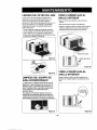
LIMPIEZA DEL FILTRO DEL AIRE
El filtro del aire se ira ensuciando a medida que va
atrapando elpolvo proveniente delaire interior. Es
preciso lavar el filtro del aire al menos cada dos
semanas. Si elfiltro del aire permanece Ilenode polvo, el
flujo de aire disminuir&y se reducir_lla capacidadde
enfriamiento del equipo, con posibles dafios para la
unidad. (Figura 25)
• Tire de la rejilla de entrada hacia delante agarrando
ambas leng_etas y tire del filtro del airehasta sacarlo.
• Lave el filtro del aireen agua tibia a. Aseg0rese de
eliminar toda el agua sacodiendo el filtro antes de volver
aponerlo en su posici6n. (Figura26)
Figura 25
Figura 26
LIMPIEZA DEL EQUIPO DE
AIRE ACONDICIONADO
La rejinafrontal yla rejUlade entrada del aire pueden
lavarse con un patio humedecido en una soluci6n de
detergente suave. El gabinete puede lavarse con un
jab6n o detergente suave y agua tibia, seguidamente
puede pulirse con cera liquida especial para
electrodom_sticos.
Para asegurar una eficiencia mdxima continua, los
serpentines del condensador (lado de enfrente de la
unidad) deben revisarse ped6dicamente y limpiarse si
est&nobstruidos con hollfn o con sucio de la atm6sfera.
Figura27
COMO A REEMPLAZA EL
GRILLE ANTERIOR
• Saque el tornillo que mantiene la reji!la frontal en
posici6n.
• Quite el tornillo que asegura le reja delantera.
• Empuje la rejilla hacia arriba de abajo y jale la parte de
arriba de la rejilla lejosde la base para levantar las
lenguetas de arriba hacia afuera de las ranuras.
i
Rejilla de entrada
I_0 I _ _/_ Rejilla de anterior
COMO A REEMPLAZA EL
GRILLEANTERIOR
Pegue el panel frontal a la caja insertando los
fijadores en el panel adentro las aberturas de la
caja.
Figura 29
- 34 -

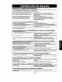
ANTES DE LLAMAR PARA SERVIClO
Cheque la siguiente lista para asegurarse si en realidad es necesario Ilamar para servicio. Una referencia rapida a
este manual puede evitar una Ilamada para servicio innecesaria.
EL EQUIPO DE AIRE ACONDICIONADO NO FUNCIONA.
Elenchufenoesfa¢onectadeenla tomadecomentedepared
Elfusibleestaquemadeoel inlerruptordeolrcur[osehadisparado
ElselectordelventiladerMODEestaenla pasic_dedeOFF
Launidadseapag5y serely16aencenderdemasiader_ido
ElcontroldetemperaturaTEMPseajustomascatidoque la
Conecteetenchufefirmementeenlatomadecomenfedepared
Resmplaceelfusibledafladeconunfusibledeacc_nretafdedeoreajusteel
inteauptordeOrcuito.
Pongael so_ctorenla posK;bndeCOOL
Apaguelaunidedyespere3minulosantesdevolveraencendelta
Gireelcont[oldetemparafuraenelsentidodelasagujasdelrelojbasrauna
graduaoldemasfria(numeromasalto)
EL AIRE DE LA UNLOAD NO SALE BASTANTE FR[O.
El selectora unaposici6nrn_sLOWCOOL.
Elc(x_oldete'nperat_ra]EMPsea_st6dem&_adocalide(nurreromasI:_o).
Latemperaturaambienteestaperdebajodetes700F (21°C)
El tubesensorc_ temperaturaestatocandoel serpantinevaporador
queest_situadodetrasdelltltrodelaire.
GireelselectoraunaposlcionHIGHCOOL.
Gireelcontroldetem_ratura enelseniidode lesaQuJasdel relojpara
Nopuedeproduolrseelenfdamientohaelaquelatemperaturaambientesuba
perencimadelos70°F (21°C).
Endereceel tu_ elejandelodel serpentinevaporador.
Elfiltrodel airepuedeestarsucio.
Elcontroldetemperaturasealustodemasiadofrloparael enf_miento
nectumo.
ELAIREACONDICIONADOENFRjA,PEROLAHABITACI_SESIENTEDEMASIADOCAUDA;SEFORMAHIELOENELSERPEN11"NDEENFRtAMIENTO
DET_SDELPANELDECORA'flVOFRONTAL
Latemperaturaanbienteenelexte_xest_perdepajodelos70°F(21°C), ParadescongelarelserpentinIleveel selectorala posicideFAN
Seguidarnente,gireelcontroldetemparaturaTEMPenelsentidedelasagujas
delrelojparaIlevarlohastauna9raduac_nms calida,
Umpieetltltro.Consultelasecc_n"Mantenimiento".Paradescongelar,Ileveel
selectoralapesiclonFAN,
Paradescongelarelserpentlo,Ileveel selectorala paelc_nFAN.
Seguidamenteajusteelcontroldetemparaturaa unapeaici6nmascalida.
ELAIREACONDICIO_,DOENFR_PEROLAHABITACI()NSESIENTEDEMASIADOC/_LIDA;NOSEFORMAHIELOENELSERPENTINDE
ENFRIAMIENTODETRASDELPANELDECORATIVOFRONTAL.
Elhltrodelaireeslasuo;oconIoquese restdngeel ltujodelaire.
ElcontroldetemperaturaTEMPsegrade6enposicidedemeslado_lida.
Lapanefrontaldelaunidadestabloqeaadaparcortines,parsianes,
mueblesetc.querestfinqenladishideddedelaire.
Laspuedes,ventanas,rejillasdecalefacci_,etcetera,estanal_ertescon
_ quesepermiteelescapedelairefdo.
Launidadacabadeencenderseenunahabitaoloncoliente.
Umpieelflltrodelaire.Consultelasesck_"Mantenimiento".
Gireel conlrddetemparafuraenelsentidodelasagujasdelrelejparaIlevarioa
unaQraduasi_masfria (Nomerornasalto)
Elirolneelblcquesenfrestedela_unidad.
Cierrelespuedas,ventesas,rejillasdecalefaeslon,etcetera.
PermltaqueIraescorraunpesorn&sde_ernp_paraeliminarel"cabralmacenado"
enlasparedes,ellecho,elp,zsoy lesmeables.
EL EQUIPO DE AIRE ACONDICIONADO SE APAGA Y SE ENCIENDE RAPIDAMENTE .
I' 'e'r' elur-x'e'o--x'rea'a'aoctoc''es'e
SE ESCUCHAN RUIDOS CUANDO LA UNLOADEST.A.ENFRIANDO.
Elsonidodelventliadoralchesarcontraelaguadelsistemade Estoesnormalcuandelahumedadesalta.Cierrelespuertas,ventanasy rejillas
elirninad,bndehumedad, decelefaesi_
Vib_ delaveatax_a;instalack_defiolente. Lealesinstruesionesdeinstalesk_oconsu_ealiestelader.
EL AGUA GOTEA DENTRO DE LA HABITACI_N CUANDO LA UNLOADEST/_ ENFRIANDO.
I I.*,e ele, deai,'ea, ,de,,ade
d_',ajeddagu&LeaI__ deins_ad6noo_nsultesiinsl_adc_.
ELAGUA GOTEA AFUERA CUANDO LA UNLOADEST,&.ENFRIANDO.
habitaclonLaunidadest_exlrayendegresdescantidadesdehumedaddeesah0med& JEstoeselgonormaldurantelosdiesexceswamenteht]rnedes. J
- 35 -
/

Get itfixed, at your home or ours!
Your Home
For repair- in your home--of all major brand appliances,
lawn and garden equipment, or heating and cooling systems,
no matter who made it, no matter who sold it!
For the replacement parts, accessories and
owner's manuals that you need to do-it-yourself.
For Sears professional installation of home appliances
and items like garage door openers and water heaters.
1-800-4-MY-HOME ° (1-800-469-4663)
Call anytime, day or night (U.S.A. and Canada)
www.sears.com www.sears.ca
Our Home
For repair of carry-in items like vacuums, lawn equipment,
and electronics, call or go on-line for the location of your nearest
Sears Parts & Repair Center.
1-800-488-1222
Call anytime, day or night (U.S.A. only)
www.sears.com
To purchase a protection agreement on a product serviced by Sears:
1-800-827-8855 (U.S.A.) 1-800-361-8865 (Canada)
Para pedir servicio de reparaci n
a domicilio, y para ordenar piezas:
1-888"SU'HOGAR _
(1-888-784-6427)
Au Canada pour service en fran ais:
1-800-LE-FOYER Mc
(1-800-533-6937)
www.sears.ca
S_E/ARS
a Registered Trademark / TMTrademark / s_ Service Mark of Sears, Roebuck and CO.
rJMarca Registrada / TMMarca de F brica / s_ Marca de Servicio de Sears, Roebuck and Co.
MCMarque de commerce / _o Marque d pos e de Sears, Roebuck and Co. ' Sears, Roeb4Jckand Co.
Part No.: 3828A20145Y
-
 1
1
-
 2
2
-
 3
3
-
 4
4
-
 5
5
-
 6
6
-
 7
7
-
 8
8
-
 9
9
-
 10
10
-
 11
11
-
 12
12
-
 13
13
-
 14
14
-
 15
15
-
 16
16
-
 17
17
-
 18
18
-
 19
19
-
 20
20
-
 21
21
-
 22
22
-
 23
23
-
 24
24
-
 25
25
-
 26
26
-
 27
27
-
 28
28
-
 29
29
-
 30
30
-
 31
31
-
 32
32
-
 33
33
-
 34
34
-
 35
35
-
 36
36


Kenmore 580.72187200 El manual del propietario
- Tipo
- El manual del propietario
en otros idiomas
- English: Kenmore 580.72187200 Owner's manual
Artículos relacionados
-
Kenmore 580.72187300 El manual del propietario
-
-
-
Kenmore 580.74054400 El manual del propietario
-
-
Kenmore 580.72124300 El manual del propietario
-
-
-
-
Kenmore 75101 10,000 El manual del propietario