Craftsman 247.88833 El manual del propietario
- Categoría
- Lanzadores de nieve
- Tipo
- El manual del propietario
Este manual también es adecuado para

Operator's Manual
P R 0 F E S S I 0 N A L
33" SNOW THROWER
Model No. 247.88833
CAUTION: Before using
this product, read this
manual and follow all
safety rules and operating
instructions.
, SAFETY
, ASSEMBLY
, OPERATION
, MAINTENANCE
, PARTS LIST
o ESPANOL
Sears, Roebuck and Co., Hoffman Estates, IL 60179, U.S.A.
Visit our website: www.craftsman.com FORMNO.769-04061A
2/4/2009

WarrantyStatement..................................Page2
SafeOperationPractices..........................Pages3-6
SafetyLabels............................................Page7
Assembly..................................................Pages8-11
Operation..................................................Pages12-15
ServiceandMaintenance.........................Pages16-23
Off-SeasonStorage..................................Page24
Troubleshooting........................................Page25
PartsList...................................................Page26-41
RepairProtectionAgreement...................Page46
Espa_ol.....................................................Page47
ServiceNumbers......................................BackCover
CRAFTSMAN PROFESSIONAL LiMiTED WARRANTY
Two Years on Snow Thrower
Whenoperatedandmaintainedaccordingtoall suppliedinstructions,if thissnowthrowerfailsduetoadefectin materialor workmanshipwithintwoyearsfrom
thedateor purchase,call 1-800-4-MY-HOME®toarrangefor freerepair.
Thiswarrantyappliesfor onlyoneyearfromthe dateof purchaseif thissnowthroweris everusedforcommercialorrentalpurposes.
Duringthefirst yearofpurchase,therewill benochargefor warrantyservicein yourhome.Foryourconvenience,in-homewarrantyservicewill stillbeavailable
afterthefirstyearofpurchase,but atrip chargewill apply.This chargewillbe waivedifyoutransportthe snowthrowerto anauthorizedCraftsmandrop-off
location.Forthe nearestauthorizedlocation,call1-800-4-MY-HOME®.
ThiswarrantycoversONLYdefectsin materialand workmanship.SearswillNOTpayfor:
• Expendableitemsthat becomewornduringnormaluse,includingbut notlimitedto skidshoes,shaveplate,shearpins,sparkplug,air
cleaner,belts,andoilfilter.
• Standardmaintenanceservicing,oil changes,ortune-ups.
• Tirereplacementorrepaircausedbypuncturesfromoutsideobjects,suchas nails,thorns,stumps,or glass.
• Tireorwheelreplacementor repairresultingfrom normalwear,accident,orimproperoperationormaintenance.
• Repairsnecessarybecauseofoperatorabuse,includingbut notlimitedto damagecausedbyimpactingobjectsthat bendthe frameor
crankshaft,orover-speedingthe engine.
• Repairsnecessarybecauseofoperatornegligence,includingbutnotlimitedto, electricalandmechanicaldamagecausedbyimproper
storage,failureto usethe propergradeandamountofengineoil,orfailuretomaintainthe equipmentaccordingtothe instructions
containedinthe operator'smanual.
• Engine(fuelsystem)cleaningor repairscausedbyfueldeterminedto becontaminatedor oxidized(stale).Ingeneral,fuelshouldbe
usedwithin30 daysof itspurchasedate.
• Normaldeteriorationandwearofthe exteriorfinishes,or productlabelreplacement.
Thiswarrantyappliesonlywhilethisproductiswithinthe UnitedStates.
Thiswarrantygivesyouspecificlegalrights,and youmayalsohaveotherrightswhichvaryfromstateto state.
Sears, Roebuckand Co.,Hoffman Estates,IL 60179
EngineOilType: SAE5W-30
EngineOilCapacity: 28ounces
FuelCapacity: 4 Quarts
SparkPlug: Champion®RC12YC
SparkPlugGap: .030"
Model Number.................................................................
Serial Number .................................................................
Dateof Purchase.............................................................
Recordthemodelnumber,serialnumber
anddateof purchaseabove
©SearsBrands,LLC
2

Thissymbolpointsoutimportantsafetyinstructionswhich,if not
followed,couldendangerthepersonalsafetyand/orpropertyof
yourselfandothers.Readandfollowall instructionsin thismanual
beforeattemptingtooperatethismachine.Failuretocomplywith
theseinstructionsmayresultin personalinjury.Whenyouseethis
symbol,HEEDITSWARNING!
CALIFORNIA PROPOSITION 65
EngineExhaust,someof itsconstituents,andcertainvehicle
componentscontainoremitchemicalsknowntoStateofCalifornia
tocausecancerandbirthdefectsorotherreproductiveharm,
Thismachinewasbuilttobeoperatedaccordingtothesafeopera-
tionpracticesinthis manual.Aswithanytypeof powerequipment,
carelessnessorerroron thepartoftheoperatorcanresultin serious
injury.Thismachineiscapableofamputatingfingers,hands,toes
andfeetandthrowingdebris.Failuretoobservethefollowingsafety
instructionscouldresultin seriousinjuryor death.
Your Responsibility--Restrict theuseofthis powermachineto
personswhoread,understandandfollowthewarningsand instruc-
tionsin thismanualandon themachine,
SAVE THESE INSTRUCTIONS!
TRAiNiNG
• Read,understand,andfollowall instructionson themachineand
in themanual(s)beforeattemptingtoassembleandoperate.
Failuretodo socan resultinseriousinjurytotheoperatorand/
orbystanders.Keepthismanualin a safeplaceforfutureand
regularreferenceandfororderingreplacementparts.Forques-
tionscall,1-800-659-5917.
• Befamiliarwithall controlsandtheirproperoperation.Knowhow
tostopthemachineanddisengagethemquickly.
• Neverallowchildrenunder14yearsofagetooperatethis
machine.Children14andovershouldreadandunderstandthe
instructionsandsafeoperationpracticesin thismanualandon
themachineandbe trainedandsupervisedbyanadult.
• Neverallowadultstooperatethis machinewithoutproper
instruction.
• Thrownobjectscancauseseriouspersonalinjury.Planyour
snow-throwingpatterntoavoiddischargeof materialtoward
roads,bystandersandthelike.
• Keepbystanders,petsandchildrenat least75feetfromthe
machinewhileitisinoperation.Stopmachineifanyoneenters
thearea.
• Exercisecautiontoavoidslippingor falling,especiallywhen
operatinginreverse.
PREPARATION
Thoroughlyinspecttheareawheretheequipmentistobeused.
Removeall doormats,newspapers,sleds,boards,wiresandother
foreignobjects,whichcouldbe trippedoverorthrownbytheauger/
impeller.
Alwayswearsafetyglassesor eyeshieldsduringoperationand
whileperformingan adjustmentor repairto protectyoureyes.
Thrownobjectswhichricochetcancauseseriousinjurytothe
eyes.
Donotoperatewithoutwearingadequatewinteroutergarments.
Donotwearjewelry,longscarvesorotherlooseclothing,which
couldbecomeentangledinmovingparts.Wearfootwearwhich
willimprovefootingonslipperysurfaces.
Usea groundedthree-wireextensioncordand receptacleforall
machineswithelectricstartengines.
Disengageall controlleversbeforestartingtheengine.
Adjustcollectorhousingheighttocleargravelorcrushedrock
surfaces.
Neverattempttomakeanyadjustmentswhileengineis running,
exceptwherespecificallyrecommendedintheoperator'smanual.
Letengineandmachineadjusttooutdoortemperaturebefore
startingtoclearsnow.
3

SafeHandlingof Gasoline
Toavoidpersonalinjuryor propertydamageuseextremecarein
handlinggasoline.Gasolineisextremelyflammableandthevaporsare
explosive.Seriouspersonalinjurycanoccurwhengasolineisspilled
onyourselfor yourclotheswhichcanignite.Washyourskinand
changeclothesimmediately.
• Useonlyanapprovedgasolinecontainer.
• Extinguishall cigarettes,cigars,pipesandothersources
ofignition.
• Neverfuelmachineindoors.
• Neverremovegascapor addfuelwhiletheengineishot
or running.
• Allowenginetocoolat leasttwo minutesbeforerefueling.
• Neveroverfillfueltank.Filltanktono morethan1/2inch
belowbottomoffillerneckto providespaceforfuel
expansion.
• Replacegasolinecapandtightensecurely.
• Ifgasolineisspilled,wipeit offtheengineandequipment.
Movemachinetoanotherarea.Wait5 minutesbefore
startingtheengine.
• Neverstorethemachineor fuelcontainerinsidewhere
thereisanopenflame,sparkor pilotlight(e.g.furnace,
waterheater,spaceheater,clothesdryeretc.).
• Allowmachinetocoolatleast5 minutesbeforestoring.
• Neverfillcontainersinsideavehicleor ona truckor trailer
bedwitha plasticliner.Alwaysplacecontainersonthe
groundawayfromyourvehiclebeforefilling.
• If possible,removegas-poweredequipmentfromthetruck
ortrailerand refueliton theground.If thisisnotpossible,
thenrefuelsuchequipmentona trailerwitha portable
container,ratherthanfromagasolinedispensernozzle.
• Keepthenozzleincontactwiththe rimofthefueltankor
containeropeningatalltimesuntilfuelingiscomplete.Do
notusea nozzlelock-opendevice.
OPERATION
• Donotputhandsorfeetnear rotatingparts,in theauger/impeller
housingor chuteassembly.Contactwiththerotatingpartscan
amputatehandsandfeet.
• Theauger/impellercontrolleverisa safetydevice.Neverbypass
itsoperation.Doingsomakesthemachineunsafeandmaycause
personalinjury.
• Thecontrolleversmustoperateeasilyin bothdirectionsand
automaticallyreturntothedisengagedpositionwhenreleased.
• Neveroperatewitha missingor damagedchuteassembly.Keep
all safetydevicesin placeandworking.
• Neverrunanengineindoorsor ina poorlyventilatedarea.Engine
exhaustcontainscarbonmonoxide,anodorlessanddeadlygas.
• Donotoperatemachinewhileundertheinfluenceofalcoholor
drugs.
• Mufflerandenginebecomehotandcancausea burn.Donot
touch.Keepchildrenaway.
• Exerciseextremecautionwhenoperatingon orcrossinggravel
surfaces.Stayalertforhiddenhazardsor traffic.
• Exercisecautionwhenchangingdirectionandwhileoperatingon
slopes.
• Planyoursnow-throwingpatternto avoiddischargetowards
windows,walls,carsetc.Thus,avoidingpossibleproperty
damageor personalinjurycausedbya ricochet.
• Neverdirectdischargeatchildren,bystandersand petsor allow
anyoneinfrontofthemachine.
• Donotoverloadmachinecapacitybyattemptingtoclearsnowat
toofastof a rate.
• Neveroperatethis machinewithoutgoodvisibilityorlight.Always
be sureofyourfootingand keepa firmholdon thehandles.Walk,
neverrun.
• Disengagepowertotheauger/impellerwhentransportingor not
in use.
• Neveroperatemachineathightransportspeedson slippery
surfaces.Lookdownand behindand usecarewhenbackingup.
• Ifthemachineshouldstarttovibrateabnormally,stoptheengine,
disconnectthesparkplugwireandgrounditagainsttheengine.
Inspectthoroughlyfordamage.Repairanydamagebefore
startingandoperating.
• Disengageall controlleversandstopenginebeforeyouleave
theoperatingposition(behindthehandles).Waituntiltheauger/
impellercomestoa completestopbeforeuncloggingthechute
assembly,makinganyadjustments,or inspections.
• Neverputyourhandinthedischargeor collectoropenings.Do
notunclogchuteassemblywhileengineisrunning.Shutoff
engineand remainbehindhandlesuntilall movingpartshave
stoppedbeforeunclogging.
• Useonlyattachmentsandaccessoriesapprovedbythemanufac-
turer(e.g.wheelweights,tirechains,cabsetc.).
• Whenstartingengine,pullcordslowlyuntilresistanceisfelt,then
pull rapidly.Rapidretractionofstartercord(kickback)willpull
handandarmtowardenginefasterthanyoucanletgo.Broken
bones,fractures,bruisesor sprainscouldresult.
• Ifsituationsoccurwhichare notcoveredinthis manual,usecare
andgoodjudgment.ContactCustomerSupportforassistance
andthenameofyournearestservicingdealer.
CLEARING A CLOGGED DISCHARGE CHUTE
Handcontactwiththe rotatingimpellerinsidethedischargechute
is themostcommoncauseofinjuryassociatedwithsnowthrowers.
Neveruseyourhandtocleanoutthedischargechute.
Toclearthechute:
1. SHUTTHEENGINEOFF!
2. Wait 10secondstobe suretheimpellerbladeshavestopped
rotating.
3. Alwaysusea clean-outtool,notyourhands.
4

MAINTENANCE & STORAGE
• Nevertamperwithsafetydevices.Checktheirproperoperation
regularly.Refertothemaintenanceandadjustmentsectionsof
thismanual.
• Beforecleaning,repairing,or inspectingmachinedisengageall
controlleversandstoptheengine.Waituntiltheauger/impeller
cometoa completestop.Disconnectthe sparkplugwireand
groundagainsttheenginetopreventunintendedstarting.
Checkboltsand screwsforpropertightnessatfrequentintervals
tokeepthemachineinsafeworkingcondition.Also,visually
inspectmachineforanydamage.
Donotchangetheenginegovernorsettingor over-speedthe
engine.Thegovernorcontrolsthe maximumsafeoperatingspeed
oftheengine.
Snowthrowershaveplatesand skidshoesaresubjecttowear
anddamage.Foryoursafetyprotection,frequentlycheckall
componentsand replacewithoriginalequipmentmanufacturer's
(OEM)partsonly."Useofpartswhichdo notmeettheoriginal
equipmentspecificationsmayleadto improperperformanceand
compromisesafety!"
Checkcontrolleversperiodicallytoverifytheyengageanddisen-
gageproperlyandadjust,ifnecessary.Refertotheadjustment
sectioninthisoperator'smanualforinstructions.
Maintainor replacesafetyandinstructionlabels,asnecessary.
• Observeproperdisposallawsand regulationsforgas,oil,etc.to
protecttheenvironment.
Priorto storing,runmachinea few minutestoclearsnowfrom
machineand preventfreezeupofauger/impeller.
Neverstorethemachineorfuelcontainerinsidewherethereisan
openflame,sparkorpilotlightsuchasa waterheater,furnace,
clothesdryeretc.
Alwaysrefertotheoperator'smanualforproperinstructionson
off-seasonstorage.
Checkfuelline,tank,cap,andfittingsfrequentlyforcracksor
leaks.Replaceifnecessary.
Donotcrankenginewithsparkplugremoved.
AccordingtotheConsumerProductsSafetyCommission(CPSC)
andtheU.S.EnvironmentalProtectionAgency(EPA),thisproduct
hasan AverageUsefulLifeof seven(7)years,or 60 hoursof
operation.AttheendoftheAverageUsefulLifehavethemachine
inspectedannuallybyan authorizedservicedealertoensurethat
allmechanicalandsafetysystemsareworkingproperlyand not
wornexcessively.Failuretodo socanresultinaccidents,injuries
ordeath.
DO NOT MODIFY ENGINE
Toavoidseriousinjuryor death,do notmodifyengineinanyway.
Tamperingwiththegovernorsettingcanleadtoa runawayengineand
causeittooperateat unsafespeeds.Nevertamperwithfactorysetting
ofenginegovernor.
NOTICE REGARDING EMiSSiONS
EngineswhicharecertifiedtocomplywithCaliforniaandfederal
EPAemissionregulationsforSORE(SmallOff RoadEquipment)are
certifiedtooperateon regularunleadedgasoline,and mayinclude
thefollowingemissioncontrolsystems:EngineModification(EM),
OxidizingCatalyst(OC),SecondaryAirInjection(SAI)and ThreeWay
Catalyst(TWO)if soequipped.
SPARK ARRESTOR
Thismachineisequippedwithaninternalcombustionengineand
shouldnotbe usedonor nearanyunimprovedforest-covered,
brush-coveredorgrass-coveredlandunlesstheengine'sexhaust
systemisequippedwitha sparkarrestermeetingapplicablelocalor
statelaws(ifany)
Ifa sparkattesterisused,itshouldbemaintainedin effectiveworking
orderbytheoperator.IntheStateofCaliforniatheaboveis required
bylaw(Section4442oftheCaliforniaPublicResourcesCode).Other
statesmayhavesimilarlaws.Federallawsapplyonfederallands.
A sparkarresterforthemufflerisavailablethroughyournearestSears
PartsandRepairServiceCenter.

SAFETY SYMBOLS
Thispagedepictsanddescribessafetysymbolsthatmayappearonthisproduct. Read,understand,andfollowall instructionson themachine
beforeattemptingtoassembleandoperate.
i
i
READ THE OPERATOR'S MANUAL(S)
Read, understand, and follow all instructions in the manual(s) before attempting to assemble and
operate
WARNING-- ROTATING BLADES
Keep hands out of inlet and discharge openings while machine is running. There are rotating blades
inside
WARNING-- ROTATING BLADES
Keep hands out of inlet and discharge openings while machine is running. There are rotating blades
inside
WARNING-- ROTATING AUGER
Do not put hands or feet near rotating parts, in the auger/impeller housing or chute assembly.
Contact with the rotating parts can amputate hands and feet.
WARNING--THROWN OBJECTS
This machine may pick up and throw and objects which can cause serious personal injury.
WARNING--GASOLINE ISFLAMMABLE
Allow the engine to cool at least two minutes before refueling.
WARNING-- CARBON MONOXIDE
Never run an engine indoors or in a poorly ventilated area. Engine exhaust contains carbon
monoxide, an odorless and deadly gas.
WARNING-- ELECTRICAL SHOCK
Do not use the engine's electric starter in the rain
6

1.KEEPAWAYFROMROTATINGiMPELLER
ANDAUGER,CONTACTWiTHiMPELLEROR
AUGERCANAMPUTATEHANDSANDFEET.
2. USECLEAN-OUTTOOLTOUNCLOG
DISCHARGECHUTE.
3.DISENGAGECLUTCHLEVERS,STOPENGINE,
AND REMAINBEHINDHANDLESUNTILALL
MOVING PARTSHAVESTOPPEDBEFORE
UNCLOGGING OR SERViCiNGMACHINE.
TO AVOIDTHROWN OBJECTSiNJURiES,
NEVERDIRECTDISCHARGEATBYSTANDERS.
USEEXTRACAUTIONWHEN OPERATINGON
GRAVELSURFACES.
5.BEAD OPERATOR'S MANUAL.
CLEAN-OUT TOOL
7

NOTE:Referencesto rightorleft sideofthesnowthrowerare
determinedfrombehindtheunitintheoperatingposition(standing
directlybehindthesnowthrower,facingthe handlepanel).
REMOVING FROM CRATE
1. Removescrewsfromthebottomof thecratesecuringthesides,
andendsoftheshippingcrate.
2. Liftoff thetopoff ofthecrateandsetoutof thewayofthe
assemblyarea.
3. Removeanddiscardplasticbagthatcoversunit.
4. Removeanyloosepartsincludedwithunit(e.g.,Operator's
Manual,etc.).
5. Pushdownonthelowerhandleandpullunitbackoutofcrate.
6. Makecertainthecratehasbeencompletelyemptiedbefore
discardingit.
ASSEMBLY
1. Makecertainthe springsatthelowerendoftheaugeranddrive
cablesaresecurelyhookedintotheirrespectiveactuator
bracketbeforepivotingthehandleupward.RefertoFig. 10.
a. Placetheshiftleverin theF6position.
b. Removethe lowerwingknobandcarriageboltfromeach
sideoftheupperhandle.Pullupon upperhandleas shown
in Fig.1.Alignupperhandlewiththelowerhandle.Again,
makecertainthespringsatthelowerendoftheaugerand
drivecablesaresecurelyhookedintotheirrespective
actuatorbracket.Also,removeanyrubberbandssecuring
thecablestothewingnuts.
2. a. Securetheupperhandleandlowerhandlewiththetwo wing
knobsandcarriageboltsremovedearlier.
b. Tightenthetwo wingknobsalreadyinstalledin theupper
holestofirmlysecuretheupperhandleand supporttubes.
3. Aligntheupperand lowershiftrods,thenslidetheshiftrod
connectordownovertheendofthelowershiftrod.Tapthe
connectoruntilthelowerrodiscompletelythroughtheconnector.
See Fig.2.
NOTE:If theconnectoris notproperlyassembled,theshiftrodwill
pivotand youwillnotbe abletoproperlychangespeedsordirection.
NOTE:If thefullrangeof speeds(forwardandreverse)cannotbe
achieved,refertothe"MakingAdjustments"section.
4. a. Cutthecabletiesecuringthechuteassemblytothelower
chutecrankrodforshippingpurposes.
b. Removethe internalcotterpinfromtheupperchutecrank.
Slidetheupperchutecrankintothesleeveon thelower
chutecrank.See Fig.3.
c. Alignthe holein theupperchutecrankwiththeholeinthe
sleeve(ifnecessary,usea pairof plierstoassistinaligning
holes).Inserttheinternalcotterpinthroughtheholesto
securethechutecrank.SeeFig.3.
5. Removelocknutsand screwssecuringoneoftheflangekeepers
tothechuteassembly.
Figure 1
/
f
Figure2
Figure3
8

6. PlacechuteassemblyontochutebaseasshowninFig.4,
makingsurethatthenotchesengagewiththespiralendofchute
directionalcontrol.
7. Secureflangekeeperremovedearlierwithlocknutsandscrews.
Tightendownnutssecuringtheothertwoflangekeepers.SeeFig.5.
8. If notalreadydone,slipthecablesthat runfromthehandle
paneltothedischargechuteintothecableguideextendingover
thetopoftheengine.SeeFig.4.
9. Normallythecabletiesholdingthesteeringcablesagainstthe
handlearelooselyinstalledoneachsideofthelowerhandleat
thefactory.Pullthecableties tighttosecure.Cuttheexcess
fromtheendsof cableties.
Theextensioncordisfastenedwitha cabletieto therearoftheauger
housingforshippingpurposes.Cutthecabletie andremoveit before
operatingthesnowthrower.
SET-UP
Chute Clean=Out Tool
A chuteclean-outtool isfastenedtothetopoftheaugerhousing
witha mountingclip.SeeFig.6.Thetoolisdesignedtoclearachute
assemblyoficeandsnow.Thisitem,alongwiththeextensioncord,is
fastenedwithacabletieatthefactory,whichyouwereinstructedto
cutin theprevioussection.
Drift Cutters
1. Removethetwo screwsand locknutsthat secureeachdrift
Neveruseyourhandstocleara cloggedchuteassembly.Shut
offengineandremainbehindhandlesuntilall movingpartshave
stoppedbeforeusingtheclean-outtooltoclearthechuteassembly.
2. Turnthedriftcuttersaroundandpositionthemas shownin Fig.7
totheoutsideoftheaugerhousing.
3. Attachthedrift cutterswiththescrewsand locknutsremoved
earlier.
?
Figure4
Figure5
J
J
F-
f
Chute Clean=out Tool
Figure7
9
Figure6
J

Tire Pressure f
Beforeoperating,checktirepressure.Refertothetiresidewallfor
exacttiremanufacturer'srecommendedor maximumpsi.
NOTE:Ifthetirepressureisnotequalinbothtires,theunitmaynot
travelina straightpathandtheshaveplatemaywearunevenly.
ADJUSTMENTS
Skid Shoes
Thesnowthrowerskidshoesareadjustedupwardatthefactoryfor
shippingpurposes.Adjustthemdownward,ifdesired,priortooperat-
ingthesnowthrower.
• Forclosesnowremovalon a smoothsurface,raiseskidshoes
higherontheaugerhousing.
It isnotrecommendedthatyouoperatethissnowthrowerongravel
asitcaneasilypick upandthrowloosegravel,causingpersonal
injuryor damagetothesnowthrowerandsurroundingproperty.
Usea middleor lowerpositionwhentheareatobeclearedis
uneven.
NOTE:Ifyouchooseto operatethesnowthrowerona gravelsurface,
keeptheskidshoesin positionformaximumclearancebetweenthe
groundandtheshaveplate.
f
Chute Tilt
Auger
Figure8
Toadjusttheskidshoes:
1. Loosenthesixhexnuts(threeon eachside)andcarriagebolts.
Moveskidshoestodesiredposition.SeeFig.8.
2. Makecertaintheentirebottomsurfaceofskidshoeisagainstthe
groundtoavoidunevenwearon theskidshoes.
3. Retightennutsand boltssecurely.
)eed Selector Shift Lever _'
Drive
Auger
Control
Cable
Wheel
Drive
"Control
Cable
Figure9
J
10

Testing Auger Drive Control
Whentheaugercontrolisreleasedandin thedisengaged"up"posi-
tion,thecableshouldhaveverylittleslack,butshouldNOTbetight.
Referto Fig.9 forlocationofcontrols.
Priortooperatingyoursnowthrower,carefullyreadandfollowall
instructionsbelow.Performall adjustmentstoverifyyoursnow
throwerisoperatingsafelyandproperly.
1. Ina well-ventilatedarea,startthesnowthrowerengineas
instructedin theOperationsection.
2. Whilestandingintheoperator'sposition(behindthe snow
thrower),engagetheaugercontrolandallowtheaugertoremain
engagedforapproximatelytensecondsbeforereleasingthe
augercontrol.Repeatthis severaltimes.
3. Withtheenginerunningandtheaugercontrolinthedisengaged
"up"position,walktothefrontofthemachine.Confirmthatthe
augerhascompletelystoppedrotatingandshowsnosignsof
motion.
4. If theaugershowsanysignsof rotating,immediatelyreturntothe
operator'spositionand shutoff theengine.Waitforallmoving
partstostopbeforereadjustingtheaugercontrolcable.
Testing Wheel Drive Control & Speed Selector
Shift Lever
Referto Fig.9 forlocationofcontrols.
1. Movetheshiftleverintosixth(6) position.
2. Withthewheeldrivecontrolreleased,pushthesnowthrower
forward,thenpullitback.Themachineshouldmovefreely.
3. Engagethedrivecontrolandattemptto movethemachineboth
forwardandback,resistanceshouldbefelt.
4. Movetheshiftleverintothefastreverse(R2)positionand repeat
theprevioustwosteps.
If youexperiencedresistancerollingtheunit,eitherwhenrepositioning
theshiftleverfrom6 toR2orwhenattemptingtomovethemachine
withthedrivecontrolreleased,adjustthedrivecontrolimmediately.
SeeAdjustingDriveandAugerControls.
Adjusting Wheel Drive & Auger Controls
1. Frombeneaththehandle,pulldownwardon theappropriatecable
andunhookthespringfoundontheendofthecablefromits
respectiveactuatorbracket.RefertoFig.9 and10.
2. Slidethespringup thecableto exposethecablecouplerthreads
andlocknut. Referto Fig.11.
3. If adjustingthedrivecable,threadthelocknutoutward(downthe
couplertowardstheendfothethread)to lengthenthecableand
allowtheunittomovefreelywhenthecontrolis released.Thread
thelocknutinward(upthecouplertowardsthecable)toshorten
thecabletoreduceslippageand preventthemachinefrombeing
easilymovedwiththedrivecontrolengaged.
_o
Figure10
Figure11
J
Donotover-tightenthecable.Over-tighteningmaypreventtheauger
fromdisengagingandcompromisethesafetyofthesnowthrower.
4. Ifadjustingtheaugercable,threadthe locknutdownthecoupler
towardstheendofthethreadtolengthenthecableasnecessary
to stoptheaugerfromturningwhenthecontrolisreleased.
5. Reattachthespringtothe rearmostholein theactuatorbracket.
6. Repeatthewheeldriveandaugercontrolteststoverifyproper
adjustment.Repeatpreviousstepsifnecessarytoattainproper
adjustmentofeachcable.
11

f
WheelDriveControl
Headlk
SpeedSelector
_......_Shift LeverTwo-Way
ChuteControlTM
erControl
GasCa
Drift
Cutters
Chute
Assembl
WheelSteering
Control
ChuteDirectional
Control
Muffler
Angers
On/ Off Switch
SkidShoe
Nowthat youhavesetupyoursnowthrower,it's importanttobecome
acquaintedwith itscontrolsandfeatures.RefertoFigure11.
Primer
Ignition
Key
OilFill
Handle Electric
Start
OilDrain-'_( Button
ElectricStarterOutlet
J
Figure11
NOTE:Donotturntheignitionkeyinan attemptto starttheengine.
Doingsomaycauseitto break.
SPEED SELECTOR SHIFT LEVER
Theshiftleverislocatedonthe rightsideofthehandlepanel.
Placetheshiftleverintoanyofeightpositionstocontrolthe
directionoftravelandgroundspeed.
Forward
Yoursnowthrowerhassixforward(F)speeds.Positionone(1)is t 2
theslowestand positionsix (6) isthefastest. F 1
Reverse
Yoursnowthrowerhastwo reverse(R)speeds.One(1)isthe
slowerandtwo(2) isthefaster.
IGNITION KEY
Theignitionkeyisa safetydevice.It mustbefullyinsertedinorderfor
theenginetostart.Removetheignitionkeywhenthesnowthroweris
notinuse.
6 CHOKE CONTROL
5 Thechokecontrolisfoundon therearofthe
4 engineand isactivatedbyrotatingtheknob
clockwise.Activatingthechokecontrolclosesthe
3 chokeplateonthecarburetorandaidsin starting
theengine.
PRIMER
Depressingthe primerforcesfueldirectlyintotheengine'scarburetor
toaid incold-weatherstarting.
OIL FILL
Engineoil levelcanbecheckedandoiladdedthroughtheoil fill.
Meets ANSI Safety Standards
CraftsmanSnowThrowersconformtothesafetystandardoftheAmericanNationalStandardsInstitute(ANSI).
12

ON / OFF SWITCH
PressintotheONpositionwhenstartingtheengineand willshutoff
theenginewhenmovedintotheOFFposition.
RECOIL STARTER HANDLE
Thishandleisusedto manuallystarttheengine.
ELECTRIC STARTER BUTTON
Pressingtheelectricstarterbuttonengagestheengine'selectric
starterwhenpluggedintoa 120Vpowersource.
ELECTRIC STARTER OUTLET
Requirestheuseof athree-prongoutdoorextensioncord(included)
anda 120Vpowersource/walloutlet.
f
NOTE:Alwaysreleasethewheeldrivecontrolbeforechanging
speeds.Failuretodo sowillresultinincreasedwearon yourmachine's
drivesystem.
AUGERS
Whenengaged,theaugersrotateanddrawsnowintotheauger
housing.
CHUTE ASSEMBLY
Snowdrawnintotheaugerhousingisdischargedoutthechute
assembly.
GAS CAP
Unthreadthegascaptoaddgasolinetothefueltank.
AUGER CONTROL
S
J
Theaugercontrolislocatedontheleft handle.Squeezethecontrol
gripagainstthehandletoengagetheaugersandstartsnowthrowing
action.Releasetostop.
TWO-WAY CHUTE CONTROL TM
Thedistancesnowisthrowncanbe changedbyadjustingtheangle
ofthechuteassembly.Movethechutecontrolforwardtodecreasethe
distance,towardthe rearto increase.
CHUTE DIRECTIONAL CONTROL
Thechutedirectionalcontrolislocatedontheleftsideofthesnow
thrower.
• Tochangethedirectioninwhichsnowisthrown,crankclockwiseto
dischargetotheleftandcounterclockwisetodischargetotheright.
SKID SHOES
Positiontheskidshoesbasedonsurfaceconditions.Adjustupward
forhard-packedsnow.Adjustdownwardwhenoperatingon gravelor
crushedrocksurfaces.
WHEEL STEERING CONTROLS
Theleftand rightwheelsteeringcontrolsarelocatedon theunderside
ofthehandles.Squeezethe rightcontroltoturnright;squeezethe left
controlto turnleft.
NOTE:Operatethesnowthrowerin openareasuntilyouarefamiliar
withthesecontrols.
HEADLIGHT
Theheadlightislocatedontopofthehandlepanel.It maybe adjusted
bylooseningthescrewsoneachsideofthelighthousing,pivotingthe
lightupor down,and retighteningthe screws.
WHEEL DRIVE CONTROL/AUGER CONTROL
LOCK
Thewheeldrivecontrolislocatedon therighthandle.Squeezethe
controlgripagainstthehandletoengagethewheeldrive.Release
tostop.TheWheeldrivecontrolalsolockstheaugercontrolsoyou
canoperatethechutedirectionalcontrolwithoutinterruptingthesnow
throwingprocess.If theaugercontrolisengagedsimultaneouslywith
thewheeldrivecontrol,theoperatorcanreleasetheaugercontrol(on
thelefthandle)andtheaugerswill remainengaged.Releaseboth
controlstostoptheaugersandwheeldrive.
DRIFT CUTTERS
Thedriftcuttersaredesignedforuseindeepsnow.Theiruseis
optionalfornormalsnowconditions.
CLEAN-OUT TOOL
Thechuteclean-outtoolisconvenientlyfastenedtotherearofthe
augerhousingwitha mountingclip.Shouldsnowand icebecome
lodgedinthechuteassemblyduringoperation,proceedasfollowsto
safelycleanthechuteassemblyandchuteopening.
13

CLEAN-OUT TOOL
Neveruseyourhandstocleara cloggedchuteassembly.Shut
off engineand remainbehindhandlesuntilallmovingpartshave
stoppedbeforeunclogging.
Thechuteclean-outtoolisconvenientlyfastenedtotherearofthe
augerhousingwitha mountingclip. Shouldsnowandicebecome
lodgedin thechuteassemblyduringoperation,proceedasfollowsto
safelycleanthechuteassemblyandchuteopening:
1. ReleaseboththeAugerControlandtheWheeldrivecontrol.
2. Stoptheenginebyremovingtheignitionkey.
3. Removetheclean-outtoolfromtheclipwhichsecuresittothe
rearoftheaugerhousing.
4. Usetheshovel-shapedendof theclean-outtooltodislodgeand
scoopanysnowand icewhichhasformedinandnearthechute
assembly.
5. Refastentheclean-outtooltothemountingclipontherearof
theaugerhousing,reinserttheignitionkeyandstartthesnow
thrower'sengine.
6. Whilestandingintheoperator'sposition(behindthesnow
thrower),engagetheaugercontrolfora fewsecondstoclearany
remainingsnowandicefromthechuteassembly.
BEFORE STARTING ENGINE
Read,understand,andfollowall instructionsandwarningson the
machineand inthismanualbeforeoperating.
Oil
Theunitwasshippedwithoil intheengine.Checkoil levelbeforeeach
operationto ensureadequateoilin theengine.Forfurtherinstructions,
refertotheService& Maintenancesectionofthismanual.
1. Removethedipstickfromtheoil fill.
2. Checkand makesurethatthelevelofoil isuptothe FULLmark
onthedipstick.
3. Iftheoil levelisnotupto FULL,pourfreshmotoroil (5W-30,with
a minimumclassificationofSF/SG/SH/SJ)slowlythroughthe
opening.Replaceoil filldipstickandcheckoil levelagain.
Gasoline
• Storegasolineinaclean,approvedcontainerandkeepthecapin
placeonthecontainer.
• Makesurethatthecontainerfromwhichyoupourthegasolineis
cleanandfreefromrustor otherforeignparticles.
Useextremecarewhenhandlinggasoline.Gasolineisextremely
flammableandthevaporsareexplosive.Neverfuel themachine
indoorsor whiletheengineishotor running.Extinguishcigarettes,
cigars,pipesandothersourcesofignition.
NOTE:A plasticdustcapmaybefoundinsidethefuelfillopening.
Removeanddiscard,if present.
• Alwaysfillthefueltankoutdoorsand usea funnelor spoutto
preventspilling.
• Fillfueltankwithclean,fresh,unleadedgasolinewitha minimum
of85 octane.Freshfuelpreventsgumfromforminginthefuel
systemoronessentialcarburetorparts.Purchasefuelin a
quantitythatcanbeusedwithin30 days.
• Neverfillthefueltankcompletely.Fillthetanktowithin1-1/2"
fromthetoptoprovidespaceforexpansionoffuel.
• Makesuretowipeoff anyspilledfuelbeforestartingtheengine.
STARTING THE ENGINE
1. Makecertainboththeaugercontrolandwheeldrivecontrolarein
thedisengaged(released)position.
2. Insertignitionkeyintoslot.Makesureitsnapsintoplace.Donot
attempttoturnthekey.
NOTE:Theenginecannotstartwithoutthekeyisfully insertedintothe
ignitionswitch.
Electric Starter
Determinethatyourhome'swiringisa three-wiregroundedsystem.
Aska licensedelectricianifyouarenotcertain.
Theoptionalelectricstarterisequippedwitha groundedthree-wire
powercordandplug,and isdesignedto operateon 120voltAC
householdcurrent.It mustbeusedwitha properlygroundedthree-
prongreceptacleatall timestoavoidthepossibilityofelectricshock.
Followall instructionscarefullypriortooperatingtheelectricstarter.
Ifyouhavea groundedthree-prongreceptacle,proceedasfollows:
1. Plugtheextensioncordintotheoutletlocatedon theengine's
surface.Plugtheotherendof extensioncordintoa three-prong
120-volt,grounded,ACoutletina well-ventilatedarea.
2. Rotatechokecontrolto FULL I,,q¢lchokeposition(fora cold
enginestart).
NOTE:Iftheengineisalreadywarm,placechokecontrolin theOFF
I _ I positioninsteadof FULLIJl'
3. Depressprimer.If itis 15°For higherpushprimertwotimes,if
below15°F,pushprimerfourtimes.
4. PushrockerswitchtoONposition.
5. Pushstarterbuttonto startengine.
Toprolongstarterlife,useshortstartingcycles(5secondsmaximum
thenwaitone minute).
6. Oncetheenginestarts,releasestarterbutton.
7. Allowtheenginetowarmupseveralminutes,adjustingchoke
towardRUNposition.Waituntilenginerunssmoothlybeforeeach
chokeadjustment.
8. Whendisconnectingtheextensioncord,alwaysunplugtheend
atthethree-prongwalloutletbeforeunpluggingtheoppositeend
fromthesnowthrower.
14

Recoil Starter
1. RotatechokecontroltoCHOKE Ill position.
2. Depressprimer.Ifit is 15°For higherpushprimertwotimes,if
below15°F,pushprimerfourtimes.
3. Pushrockerswitchto ONposition.
4. Grasptherecoilstarterhandleand slowlypullthe ropeout.At
thepointwhereitbecomesslightlyhardertopulltherope,slowly
allowtheropeto recoil.
5. Pullthestarterhandlewitha firm,rapidstroke.Donotrelease
thehandleandallowittosnapback.Keepa firmholdonthe
starterhandleandallowittoslowlyrecoil.
6. Allowtheenginetowarmup severalminutes,adjustingchoke
towardRUNposition.Waituntilenginerunssmoothlybeforeeach
chokeadjustment.
STOPPING THE ENGINE
Runenginefora fewminutesbeforestoppingtohelpdryoff any
moistureontheengine.
1. PushtheOn/ OffswitchtotheOFFposition.
DoNOTmovethechokecontrolto CHOKE IJl positionto stop
theengine.Backfireor enginedamagemayoccur.
.
3.
Removetheignitionkeyandstoreina safeplace.
Wipeall snowandmoisturefromtheareaaroundtheengineas
wellastheareainandaroundthewheeldrivecontrolandauger
control.Also,engageandreleasebothcontrolsseveraltimes.
TO ENGAGE WHEEL DRIVE
1. Moveshiftleverintooneofthesixforward(F) positionsor two
reverse(R)positions.Selecta speedappropriateforthesnow
conditionsand a paceyou'recomfortablewith.
NOTE: Whenselectinga DriveSpeed,usetheslowerspeedsuntil
youarecomfortableandfamiliarwiththeoperationofthesnow
thrower.
REPLACING SHEAR PINS
Theaugersare securedtothespiralshaftwithtwo shearpinsandcot-
terpins.If theaugershouldstrikea foreignobjector icejam, thesnow
throwerisdesignedsothattheshearpinsmayshear.Iftheaugerswill
notturn,checktoseeifthepinshavesheared.SeeFigure12.
NEVERreplacetheaugershearpinswithanythingotherthanOEM
PartNo.738-04155replacementshearpins.Anydamagetothe
augergearboxor othercomponentsasa resultoffailingtodo sowill
NOTbecoveredbyyoursnowthrower'swarranty.
Alwaysturnoff thesnowthrower'sengineand removethekeypriorto
replacingshearpins.
f
ii
Figure12
J
2. Squeezethewheeldrivecontrolagainstthehandlethesnow
throwerwillmove.Releaseitand drivemotionwillstop.
NOTE:NEVERrepositiontheshiftlever(changespeedsordirection
oftravel)withoutfirstreleasingthewheeldrivecontrolandbringing
thesnowthrowertoa completestop.Doingsowillresultinpremature
weartothesnowthrower'sdrivesystem.
TO ENGAGE AUGERS
1. Toengagetheaugersandstartthrowingsnow,squeezethe
augercontrolagainsttheleft handle.Releasetostoptheaugers.
15

ENGINE MAINTENANCE
Beforelubricating,repairing,or inspecting,disengageallcontrolsand
stopengine.Waituntilallmovingpartshavecometoa completestop.
Removetheignitionkeytopreventunintendedfiringoftheengine.
Checking Engine Oil
1. Besureengineisuprightand level
2. Unscrewoil fillcapfromoil fillertubeandwipedipstickclean.
3. Screwoil fillcapbackintooil fillertube.Tightensecurely.
4. Unscrewand removeoilfillcapfromoilfillertube.Noteoil level.
Ifoil readingondipstickisbelow"ADD"mark,slowlyaddoil to
reach"FULL"level.SeeFigure13.
5. Screwoil fillcapbackintooil fillertube.Tightensecurely.
6. Wipeawayanyspilledoil.
Changing Engine Oil
Toavoidenginedamage,it isimportantto:
• Checkoil levelbeforeeachuseandeveryeightoperatinghours.
• Changeoil afterfirst5 to8 operatinghoursandevery50operat-
inghoursor oncea seasonthereafter.
1. Placeenginelevelandremovesafetykey.
2. WithengineOFFbutstillwarm,removeoil drainpluganddrainoil
intoan appropriatereceptacle.SeeFigure13.
Usedoilisa hazardouswasteproduct.Disposeofusedoil properly.
IDonotdiscardwithhouseholdwaste.Checkwithyourlocalauthori-
_tiesor SearsServiceCenterforsafedisposal/recyclingfacilities.
3. Reinstalloildrainplugandtightensecurely.
4. Refilltheenginewith recommendedoil.See RecommendedOil
Usagechart.Theengine'soil capacityis20 ounces.
Recommended Oil Usage
f
f
,.J
..J
LI..
a
a
Maintain oil level
at FULL
X._j
Figure13
Oil Drain
J
i¸ i!i!i¸iii¸,!i!i
Figure14
5. Wipeawayanyspilledoil.
Checking Spark Plug
16

Checksparkplugyearlyor every100operatinghours.
1. Removechokecontrolknobandsafetykey.
2. Loosenand removethemountingscrewsfromthesnowhood.
3. Slowlyremovethesnowhood,makingsurethattheprimerbulb
hoseandignitionwireremainconnected.SeeFigure15.
4. Removeandinspectsparkplug.
5. Replacesparkplugif porcelainiscrackedorif electrodesare
pitted,burnedorfouledwithdeposits.
6. Checkelectrodegapwitha feelergaugeandsetgapto .030
(0.76ram)ifnecessary.SeeFigure16.
7. Reinstallsparkplugandtightensecurely.
8. Remountthe snowhoodtotheenginewith themountingscrews,
againmakingsuretheprimerbulbhoseandignitionwireare
connected.
9. Connectthechokecontrolknobto thechokeshaftonthe
carburetor.Ifthechokecontrolknobisnotinstalledcorrectly,the
chokewillnotoperate.
10. Installthesafetykey.
NOTE:A resistorsparkplugmustbe usedforreplacement.Contacta
SearsPartsand RepairCenterfora replacementsparkplug.
Carburetor
Enginesoperatedatabout3000to5000feet(900to 1500meters)
abovesealevelmayrequireahighaltitudecarburetormainjet. If
erraticperformanceisobserved,contacta SearsPartsand Repair
Centerforcosttoinstall/purchasea highaltitudecarburetormainjet.
Engine Speed
LUBRICATION
Drive and Shifting Mechanism
Avoidseriousinjuryor death,DONOTmodifyenginein anyway.
Tamperingwiththegovernorsettingcancausetheengineand
equipmenttooperateat unsafespeeds.NEVERtamperwithfactory
settingofenginegovernor.Runningtheenginefasterthanthespeed
setat thefactoryisdangerous.
Atleastoncea seasonorafterevery25 hoursofoperation,remove
rearcover.Lubricateallchains,sprockets,gears,bearings,shafts,and
theshiftingmechanism.Useengineoil ora spraylubricant.Referto
Figure17.
NOTE:Becarefulnottogetanyoil on thealuminumdriveplateor
rubberfrictionwheel.Doingsowillhinderthesnowthrower'sdrive
system.Wipeoff anyexcessor spilledoil.
Wheels
Atleastoncea season,removebothwheels.Cleanandcoattheaxles
witha multipurposeautomotivegreasebeforereinstallingwheels.
Chute Directional Control
Oncea season,lubricatetheeyeboltbushingandthe spiralwith
3-in-1oil.
Mounting
Screws
Knob
Figure15
f
Figure16
17
Figure17

Auger Shaft
Atleastonceaseason,removetheshearpinsonaugershaft.Spray
lubricantinsideshaft,andaroundthespacersandflangebearings
foundateitherendoftheshaft.SeeFigure18.
SHAVE PLATE AND SKID SHOES
Theshaveplateand skidshoesonthebottomofthesnowthrowerare
subjecttowear.Theyshouldbecheckedperiodicallyandreplaced
whennecessary.
Skid Shoes
NOTE:Theskidshoeson thismachinehavetwowearedges.When
onesidewearsout,theycanbe rotated1800to usetheotheredge.
1. Removethe sixcarriageboltsandhexnutsthatsecurethetwo
skidshoestothesidesoftheaugerhousing.RefertoFigure19.
2. Positionthenewskidshoesandsecurewiththecarriagebolts
andhexnuts.Makecertaintheskidshoesareadjustedtobe
level.
Shave Plate
1. Removethe hexnutsandcarriageboltsthatsecuretheshave
platetothebottomofthehousing.
2. Removethe rearmosthexnutandcarriageboltsecuringtheback
ofeachskidshoetothe sidesofthehousing.Loosenthefour
remaininghexnutssecuringtheskidshoes.
3. Slidethe shaveplateoutoftheoff-setslotatthe bottomofthe
housing,andfrombetweentheskidshoesandsidepanelsofthe
housing.
4. Withthe mountingholestowardthebackoftheunit,slidethenew
shaveplateintopositionand securewiththefastenersremoved
previously.
ADJUSTMENTS
Shift Rod
Ifthefull rangeofspeeds(forwardandreverse)cannotbe achieved,
refertoFigure20totheleftandadjusttheshiftrodasfollows:
1. Lookingunderneaththehandlepanel,notewhichof thethree
holesinthe shiftlevertheferruleis insertedinto.Alsonotethe
directionof insertion.Thenremovetheinternalcotterpinandflat
washerfromtheferruleandwithdrawtheferrulefromtheshift
lever.SeeFigure20.
2. Placeshiftleverin sixth(6) positionor fastestforwardspeed.
3. Pushshiftrodandshiftarmassemblydownsharplyasfarasit
willgo toputthedriveintothefastestforwardposition.
4. Asnecessary,rotatetheferruleupor downthe shiftroduntilthe
ferrulelinesupwiththeholefromwhichit wasearlierremoved.
SeeFigure20.
5. Fromthedirectionnotedearlier,inserttheferruleintotheproperhole.
6. Reinstallthewasherandtheinternalcotterpin.
Chute Control
Thedistancesnowisthrowncanbeadjustedbyadjustingtheangleof
thechuteassembly.RefertotheOperationsectionforinstructions.
Theremotechutecontrolcableshavebeenpreladjustedatthefactory.
18
f
f
/ /7 "'! ......_, .....
.............. _':'f!'t, .......... }_\_. _,
i _ \ .....77',!.1< ' L _k;,..... +El'\t;......
k, -Jr 7 r'W'i / '
, , _ ' ...... 7
....................,'r......................................\ i ........ +>, F .............................
J
Figure18
Figure19
t,
'ii /
Figure20

Movetheremotechuteleveronthecontrolpanelforwardtopivotthe
upperchutedown;movetheleverrearwardtopivottheupperchute
up,
Wheeldrive control
RefertotheAdjustmentsectionoftheAssemblyinstructionstoadjust
thewheeldrivecontrol,Tofurtherchecktheadjustment,proceedas
follows:
1. Withthesnowthrowertippedforward(becertaintorunthe
fueltankdrybeforetippingtheunitforward),removetheframe
coverunderneaththesnowthrowerbyremovingtheself-tapping
screws.
2. Locatetheopeningbetweentheaxlesupportbracketand
thefrontframesupport(SeeFigure21).Lookingthroughthis
opening,withthewheeldrivecontrolreleased,theremustbe
clearancebetweenthefrictionwheelandthedriveplateinall
positionsoftheshiftlever.
3. Withthewheeldrivecontrolengaged,thefrictionwheelmust
contactthedriveplate.SeeFigure21.
4. Ifthereisnofrictionwheelclearance,orthefrictionwheeldoes
notsolidlycontactthedriveplate,re-adjustthelocknutonthe
lowerendofthedrivecablefollowingtheinstructionsinthe
Assemblysection.
5. Reassembletheframecover.
Chute Bracket
Ifthespiralatthebottomofthechutedirectionalcontrolisnotfully
engagingwiththechuteassembly,thechutebracketcanbeadjusted.
Todo so:
1. Loosenthetwonutswhichsecurethechutebracketandreposi-
tionitslightly.See Figure22.
2. Retightenthenuts.
Auger Control
RefertotheAssemblysectionforinstructionsonadjustingtheauger
controlcable.
Skid Shoes
RefertotheAssemblysectionforinstructionsonadjustingtheskid
shoes.
BELT REPLACEMENT
Belt Removal Preparation
1. Disconnectthechutecrankassemblyatthedischargechuteend
byremovingthehairpinclipandtheflat washer.Referto Figure
23.
2. Removetheplasticbeltcover,locatedneartheengine,byremov-
ingthethreeself-tappingscrewsthatsecureit. SeeFigure24.
3. Loosentheboltshownin Figure25 securingthebeltkeeper
bracketandremovetheotherbolt.Pushthebeltkeeperand
bracketupoff theenginepulley.
Auger Belt Replacement
1. Removethehairpinclipandflatwasherfromtheferrulein orderto
disconnecttheaugeridlerrodfromthebrakebracketassembly.
f
Drive Axle Supp.
Plate Brkt.
Opening
Figure21
l
j_
Figure22
Figure23
19

Figure24
SeeFigure26.
NOTE:Makesurethatthelocationoftheferruleon theauger
idlerrodis maintained.
2. Sliptheaugercontrolbelt(thefrontbelt)offtheenginepulley.
3. Pullthebrakebracketassemblytowardsthecableguideroller
andunhooktheaugercable"Z" fitting.SeeFigure27.
4. Frombothsidesofthetheframeassembly,usea 1/2"wrenchto
removethethreehextapscrewssecuringtheframetotheauger
housingassembly.Referto Figure23on previouspage.
NOTE:Donotremovethelowerhexflangelocknuton eachside.
5. Placea blockofwoodunderneaththeaugerhousingasshownin
Figure28andseparateaugerhousingfromtheframebytiltingthe
housingforwardandpullingupthehandles.
6. Blocktheimpellerwitha pieceofwoodto preventit fromspinning
andusea 1/2"wrenchto removethehexscrewandflatwasher
fromthecenterofthe pulleyontheaugerhousing.See Figure29.
7. Liftthebrakebracketassemblyoutofthepulleygrooveandslide
thepulleyassemblyoffthepostsoftheaugerpulleyadapterto
removetheoldbelt.RefertoFigure29.
NOTE:Thepulleyadaptermayslideofftheaugerinputshaftwhen
removingthepulley.Useextracautiontoensuretheadapterdoesfall
and/orgetdamagedwhenremovingthepulley.
8. Placethenewaugerbeltin theV-grooveoftheaugerpulleyand
placethepulleyw/beltinsidethebeltkeepers.
9. Turnthepulleyasnecessarytoalignitsthreeslotsapproximately
withthepostsofthepulleyadapter,thenmovethebrakebracket
assemblyawayfromtheinputshaft. Whilealigningthepulley
slotsandadapterposts,pushtheaugerpulleyfullyontothe
adapter.Referto Figure29.
NOTE: If thepulleyadapterwas removedwiththepulley,alignthe
splinesofthepulleyadapterandaugerinputshaft,andpushthepulley
andadapterontotheinputshaft.Referto Figure29.
10. Slidethewasherontothehexscrewremovedearlierandapply
Loctite262tothethreadsofthehexscrew.
11. Insertthehexscrewthroughthepulleyassemblyandintothe
Loosen
Figure25
Figure26
//
f
/
//
/
/
Figure27
20

threadsoftheinputshaft.Torquethehexscrewto250-325in.
/Ibs.tosecuretheaugerpulleyassemblyontheinputshaft.
12. If alsoreplacingthedrivebelt,proceedtothe"DriveBelt"
instruction.If not,repositionthetransmissionframebackonto
theaugerhousing.Installthedrivebelton theenginepulley,
re-connecttheaugercable"Z" fittingandaugeridler rodferrule
tothebrakebracket.Repositionandsecuretheenginepulley
beltguard,andre-installthebeltcover.
NOTE:Makesureto removethepieceofwoodblockingtheimpeller.
Checktheaugerdrivebeltadjustment.Withtheaugerclutchlever
in thedisengagedposition,thetopsurfaceofthenewbeltshouldbe
evenwiththeoutsidediameterofthepulley.
Toadjust,disconnectferrulefrombrakebracketassembly.Thread
ferrulein(towardsidler)toincreasetensionon belt,or outtodecrease
belttension.
NOTE:Thebrakepuckmustalwaysbe firmlyseatedinthepulley
groovewhenaugercontrolisdisengaged.
IMPORTANT:Repeatthe"AugerDriveControlTest"fromtheAs-
semblysectionbeforeoperatingsnowthrower.
Drive Belt Replacement
If notalreadydone,removetheaugerdrivebeltfromthefrontpulleyof
theenginedoublepulley.Referto"AugerBeltReplacement"instruc-
tionsintheprevioussub-section.
1. a.Pulltheidlerpulleyawayfromthebacksideofthedrivebeltto
relievethetension.SeeFigure30.
b.Slipthedrivebeltofftheidlerpulley. Carefullyreleasetheidler
pulley.
2. Rollthedrivebeltoff thelowerdrivepulley.
3. Removethebeltfromtheenginepulley.
4. Installthenewbeltonthepulleysinthereverseorderand
re-tensionwiththeidlerpulley.
5. Reassemblebyperformingthepreviousstepsintheopposite
orderandmannerof removal.
CHANGING FRICTION WHEEL
Therubberonthefrictionwheelissubjectto wearand shouldbe
checkedperiodically.Replacethefrictionwheelifanysignsofwearor
crackingarefound.
1. Runtheunit'sfueltankdrybeforeperformingStep2.
2. Tipthesnowthrowerupandforward,sothatitrestsonthe
housing.
3. Removescrewsfromtheframecoverunderneaththesnow
thrower(referto Figure31).Removetherightwheelfromtheaxle.
Figure28
Adapter Post
f
Slot
Figure29
Figure30
21

4. Usinga 3/4"wrench,holdthehexshaftandremovethehex
screwandbellevillewasherand bearingfromleft sideofthe
frame.RefertoFigure32.
5. Holdingthefrictionwheelassembly,slidethehexshaftoutof
thefrictionwheelassemblyandtherightsideoftheframe.The
spacerontheleft sideofthehexshaftwillfallandthesprocket
shouldremainhanginglosein thechain.
6. Liftthefrictionwheelassemblyoutbetweentheaxleshaftand
thedriveshaftassemblies.
7. Removefourscrewssecuringthefrictionwheeltothehub
assembly(refertoFigure33).Discardold frictionwheel.
8. Reassemblethenewfrictionwheelontothehubassembly,
tighteningthefourscrewsin rotationandwith equalforce.It is
importanttoassemblethefrictionwheelsymmetricallyfor proper
functioning.
9. Repositionthefrictionwheelassemblyin thesnowthrowerframe.
Insertthepinfromtheshiftarmassemblyintothefrictionwheel
assemblyandholdassemblyin position.Referto Figure34.
10. Slidethe hexshaftthroughthe rightsideoftheframetowardthe
leftsideandthroughthefrictionwheelassembly.
11. Aftermakingcertainthatthechainison boththelargeandthe
smallsprocket,alignthehexshaftwith thehexhubofthesmall
sprocket,andslidetheshaftthroughthe sprocket.
NOTE:If thesprocketfellfromthesnowthrowerwhileremovingthe
hexshaft,placethesprocketon thechain.Realignthesprocketon the
chainwiththehexhubfacingthe rightsideof unit.Positionthehex
hubofthesprockettowardthefrictionwheelwhenslidingthesprocket
ontothehexshaft.
Figure31
RemoveHexScrew
BellevilleWasher
l°
HexShaft
/
FrictionWheelAss'y.
SlideHex
ShaftOut
RightSide
Figure32
J
f
Figure33
22

12. Slidethespacerontotheendofthehexshaft.
13. Alignthebearingonthe rightendofthehexshaftwiththehole
in therightsideof theframe,thenpushthehexshafttotheleft
intopositionintheframe.
14. Slidethebearingontotheleftendof thehexshaftandpressinto
theholeontheIdt sidetheframe.
15. Placethebellevillewasher(roundedsidetowardhead)ontothe
hexscrewremovedearlier,and insertthescrewintothethreaded
holeofthehexshaft.
16. Graduallytightenthehexscrewtofully seatthebearingsin each
sideoftheframeandtosecurethehexshaft.
17. Positiontheframecoveronthebottomof theframeandsecure
withtheself-tappingscrews.Pivotthesnowthrowerdowntoit
normaloperatingposition.
©
Figure34
MAINTENANCE SCHEDULE
Beforeperforminganytypeofmaintenance/service,disengageall
controlsandstoptheengine.Waituntilallmovingpartshavecometo
acompletestop.Disconnectsparkplugwireandgrounditagainstthe
enginetopreventunintendedstarting.Alwayswearsafetyglassesduring
operationorwhileperforminganyadjustmentsor repairs.
Followthemaintenanceschedulegivenbelow.Thischartdescribes
serviceguidelinesonly.UsetheServiceLogcolumntokeeptrackof
completedmaintenancetasks.Tolocate the nearestSearsService
Centeror to scheduleservice,simplycontactSearsat
1-800-4-MY-HOME®.
EachUse
1st5- 8 hours
25 hours
50 hours
Annuallyor 100hours
BeforeStorage
1 Underheavyloadorin hightemperatures
1. Engineoillevel
2. Looseor missinghardware
3. Unitandengine.
1. Engineoil
1. Engineoi11-
2. Controllinkagesandpivots
1. Engineoil
1. Sparkplug
1. Fuelsystem
= =
1. Check
2. Tightenor replace
3. Clean
1. Change
1. Change
2. Lubewithlightoil
1. Change
1. Clean,replace,re-gap
1. Runengineuntilit stopsfromlackof
fueloradda gasolineadditivetothe
gasinthetank.
23

Ifthe snowthrowerwillnotbe usedfor30 daysor longer,or ifit istheendofthesnowseasonwhenthelastpossibilityof snowisgone,the
equipmentneedstobestoredproperly.Followstorageinstructionsbelowtoensuretopperformancefromthesnowthrowerformanymoreyears.
PREPARING ENGINE
Forenginesstoredover30days:
1. Topreventgumfromforminginfuelsystemoron essentialcarbure-
torparts:
a.If fueltankcontainsoxygenatedor rdormulatedgasoline
(gasolineblendedwithan alcoholorether),runengineuntilit stops
fromlackoffuel.
Alcoholblendedfuels(calledgasoholor usingethanolor methanol)
canattractmoisturewhichleadstoseparationandformationofacids
duringstorage.Acidicgascandamagethefuelsystemofan engine
_whe n storage.
b.If fueltankcontainsgasoline,eitherrunengineuntilit stopsfrom
lackoffueloradda gasolineadditivetothegasinthetank.Ifyou
usea gasadditive,runtheengineforseveralminutestocirculate
theadditivethroughthecarburetor.
Neverstoresnowthrowerwithfuelintank indoorsor inpoorlyventi-
latedareas,wherefuelfumesmayreachan openflame,sparkor pilol
lightasona furnace,waterheater,clothesdryerorgasappliance.
.
3.
Whiletheengineisstillwarm,changetheoil.
Removethe sparkplugandpourabout1/2ounceofengineoil
throughthesparkplugholeintothecylinder.Replacesparkplug
andcranktheengineseveraltimestodistributetheoil.
PREPARING SNOW THROWER
• Whenstoringthesnowthrowerin anunventilatedormetalstor-
age shed,careshouldbetakentorustprooftheequipment.Using
a lightoilor silicone,coattheequipment,especiallyanychains,
springs,bearingsandcables.
• Removealldirt fromexteriorofengineandequipment.
• Followlubricationrecommendations.
• Storeequipmentin a clean,dryarea.
Neveruseengineor carburetorcleaningproductsin thefueltankor
permanentdamagemayoccur.
24

Beforeperforminganytyped maintenance/service,disengageall
controlsandstoptheengine.Waituntilallmovingpartshavecometo
a completestop.Disconnectsparkplugwireandgrounditagainstthe
enginetopreventunintendedstarting.Alwayswearsafetyglassesduring
operationorwhileperforminganyadjustmentsorrepairs.
Thissectionaddressesminor serviceissues.Tolocate the nearestSearsServiceCenteror to scheduleservice,simplycontactSears
at 1-800-4-MY-HOME®.
Enginefailsto start
Enginerunserratically
1. Chokecontrolnotin ONposition.
2. Sparkplugwiredisconnected.
3. Faultysparkplug.
4. Fueltankemptyor stalefuel.
5. Enginenotprimed.
6. Safetykeynotinserted.
1. EnginerunningonCHOKE.
2. Stalefuel.
3. Wateror dirtinfuelsystem.
4. Carburetoroutofadjustment.
1. Carburetornotadjustedproperly.
1. Loosepartsordamagedauger.
Engineoverheats
Excessivevibration
Lossof power 1. Sparkplugwireloose.
2. Gascapventholeplugged.
Unitfailsto propelitself 1. Drivecablein needofadjustment.
Unitfailstodischargesnow
2. Drivebeltlooseor damaged.
3. Frictionwheelworn.
1. Chuteassemblyclogged.
2. Foreignobjectlodgedin auger.
3. Augercableinneedofadjustment.
4. Augerbeltlooseor damaged.
5. Shearpin(s)sheared.
1. MovechokecontroltoONposition.
2. Connectwireto sparkplug.
3. Clean,adjustgap,or replace.
4. Filltankwithclean,freshgasoline.
5. Primeengineasinstructedin theOperationSection.
6. Insertkeyfullyintothe switch.
1. MovechokecontroltoOFFposition.
2. Filltankwithclean,freshgasoline.
3. Drainfueltank.Refillwithfreshfuel.
4. ContactyourSearsParts& RepairCenter.
1. ContactyourSearsParts& RepairCenter.
1. Stopengineimmediatelyanddisconnectsparkplug
wire.Tightenall boltsandnuts.If vibrationcontinues,
haveunitservicedbya SearsParts& RepairCenter.
1. Connectandtightensparkplugwire.
2. Removeiceandsnowfromgascap.Becertainvent
holeisclear.
1. Adjustdrivecontrolcable.RefertoServiceand
Maintenancesection.
2. Replacedrivebelt.RefertoService&Maint.section.
3. Replacefrictionwheel.
1. Stopengineimmediatelyanddisconnectsparkplug
wire.Cleanchuteassemblyandinsideofauger
housingwithclean-outtoolor a stick.
2. Stopengineimmediatelyanddisconnectsparkplug
wire.Removeobjectfromaugerwithclean-outtool
or a stick.
3. Adjustaugercontrolcable.RefertoAssembly
section.
4. Replaceaugerbelt.Referto Serviceand Mainte-
nancesection.
5. Replacewith newshearpin(s).
HEED MORE HELP?
_ _r@ the answe_ and more on _an_my_eE_eo_e_ _ _ f_e_!
o Find this and all your other product manuals onLLne.
o Get answers from our team of home experts.
o Get a personalized maintenance plan for your home,
o Find information and tools to help w}th home projects.
25

Craftsman Snow Thrower Model 247.88833
)
26

Craftsman Snow Thrower IViodel 247.88833
D = 0
05244B Housing,Bearing
2. 05845C Housing,Bearing
3. 618-04515 GearBoxAssembly,Auger
4. 618-0281A BracketAssy,AugerBrake
5. 684-0090B-0637 Impellar,16"
6. 684-04214-0721 Housing,Auger- 33"
7. 684-04151-0637 SpiralAssy,LH
8. 684-04152-0637
9. 710-1245B
10. 710-0389
11. 710-0451
12. 710-0347
13. 710-0376
14. 710-04484
SpiralAssy,RH
Screw,5/16-24x .875
Bolt,Carriage,3/8-16x .750
Screw,Carriage,5/16-18x .75
Scr,HexCap,3/8-16x 1.75
Scr,HexCap,5/16-18x 1.00
Screw,5/16-18x .750
15. J726-04012 J Nut,Push
16. 629-0071 ExtensionCord,110V
17. 710-3168 Bolt,Carriage,3/8-16x 1.0
18. 710-04606 Screw,5/16-18x .4300
19. 711-0677 Ferrule
20. 712-0116 Nut,HexLock,3/8-24
21. 712-04063 Nut,FlngeLk,5/16-18
22. 712-04065 Nut,FigLk,3/8-16
23. 741-0217 Sleeve
24. 714-0104 Pin,internalCotter
25. 714-0126 Key,HiPro,3/16x 3/4
26. 714-0135 Key,Woodruff,I/4x3/4
27. 714-04040 Pin,BowtieCotter
28. 715-0118 Pin,Spirol,5/16x 1.75
29. 725-0157 Tie,Cable
30. 731-1696A Adapter,Chute,6"
31. .738-0275 , Shf,Gear,Worm
32. 731-05163 Spacer,1.0x 1.5x 1
33. 731-2635 Clip,Mounting
34. 731-2643 Tool,Cleanout
35. 732-0858 Spring,Extension
36. 736-0159 Washer,.349x .879x .063
37. 736-0174 Washer,.625x .885x .015
38. 736-0505 Washer,Fiat,.34x 1.50x .150
D = O g
750-04020 Spacer,1.004x 1.375x .25
40. 721-0146 OilSeal
41. 736-3008 Washer,.344x .75x .12
42. 736-3046A Washer,1.01x 1.86x .06
43. 738-0281 Screw,Shoulder,.625x .17
44. 738-04155 Pin,Shear,.25x 1.75
45. 738-04158 Axle,Spiral,33"
46. 741-0192 Bearing,Flangew/Flats
47. 741-04024 Bearing,SelfAligning
48. 741-0475 Bushing,Nylon
49. 741-0494 Bushing,Flange,1.051x 1.16
50. 747-0980A Rod,AugerIdler
51. 721-0325 Plug
52. 754-04131 V Belt,l/2 x42
53. 756-0178 Pulley,Fiatidler,2.75OD
54. 756-04244A Pulley,AugerDrive,10.0
55. 784-0385B Bracket,AugerIdler
56. 790-00264A-0637 Bracket,GearBoxSupport
57. 784-5123-0637 Bracket,ChuteCrank
58. 710-0276 Screw,Carriage,5/16-18x 1.00
59. 790-00181 DriftCutter
60. 784-5714B-0637 Plate,Shave,33"
61. 741-0184 Brg,Thrust
62. 784-5697-0637 Shoe,Skid
63. 731-05162 Spacer,1.0x 1.5x 2
64. 710-3008 Screw,5/16-18x .75
65. 748-04067A Pulley,Adapter,.75Dia.
66. 618-0246 HsgAssyAugerRH(Inc.40 & 70)
67. 618-0247 HsgAssyAugerLH(Inc.40 &70)
68. 710-1260A Screw,LD,5/16-18x.750
69. 711-04714 Shf,Drive,Auger
70. 741-0670 FlangeBearing
71. 716-0111 Ext,Ret,Ring
72. 717-1425 Gear,Worm,LH
73. 721-0145 Seal,Oil
74. 736-0266 Washer,Fiat,1.52IDx2.00D
75. 736-0291 Washer,Fiat,.88IDx .38OD
76. 717-0299 Gear,Worm,DblThread
27

Craftsman Snow Thrower IViodel 247.88833
/
i
i
i
i
A
A
%
28

625-04053
2. _646-0012
3. 684-0053B-0637
4. 705-5218
5. 705-5219
6. 705-5266-0637
7. 710-0458
8. 710-0572
9. 710-1003
10. 710-1625
D _ O
Assembly,Light
CableAss'y,Auger/Drive
Crank,Chute,26.0
Handle,Engage,RH
Handle,Engage,LH
Bracket,ChuteCrank
Screw,Carr.,5/16-18x 1.75
Screw,Carr.,5/16-18x 2.5
Screw,#10-16x.625
Screw,#10-24x 1.75
11. 710-04682
12. 710-3118
13. 710-3015
14. 711-0677
15. 784-5679-0637
16. 712-04064
17. 712-3068
18. 714-0101
Screw,Hex,3/8-16x2.00
Screw,Hex,3/8-16x 1.00
Screw,Hex,1/4-20x .75
Ferrule,5/16-18x.312Dia
Brkt.,HandleSupport- LH
Nut,HexFlange,1/4-20
Nut,HexLock,5/16-18GR5
Pin,InternalCotter
19. 714-0104 Pin,internalCotter
20. 720-0201A Knob,Crank
21. 720-04039 Knob,Shift
22. 720-0284 Knob,Wing,5/16-18
23. 725-0157 Tie,Cable
24. 784-5682-0637 Brkt.,HandleSupport- RH
25. 784-5681-0637 Brkt.,HandleSupport- LH
26. •7260100 Cap,Push,3/8
27. 731-2298 Panel,Handle
28. 736-0105 Wash,Bell,.375x .87x.063
29. 736-0185 Wash,Fl.,.375x .738x .063
30. 736-0242 Wash,Bell,.34x .872x .06
31. 736-0275 Wash,FI,.344x .688x .065
32. 741-0475 Bushing,Plastic,.38ID
33. 746-0950A CableAssembly,Trigger
34. 747-0624-0637 Rod,ChuteCrank
35. 747-0983A
36. 747-0997
37. 784-5680 -0637
38. 749-0989A-0637
39. 749-0990A-0637
40. 749-0991-0637
41. 750-0963
42. 684-0102A-0721
Rod,LowerShift
Rod,UpperShift
Brkt.,HandleSupport- RH
Handle,UpperLH
Handle,UpperRH
Handle,Lower
Connector,Shift Rod
Panel,Handle
29
D _ W
710-0276 Screw,Carr,5/16-18x 1.0
44. 710-0458 Screw,Carr.,5/16-18x 1.75
45. 710-0459A Screw,Hex,3/8-24x 1.5
46. 710-0597 Screw,Hex,1/4-20x 1.0
47. 710-0599 Screw,Hx,1/4-20x .5
48. 710-0805 Screw,Hex,5/16-18x 1.5
49. 710-0895 Screw,Hx,1/4-15x .75
50. 711-0653 Pin,Clevis,.312x 1.0
51. 712-0116 Nut,insert,3/8-24
52. 712-04063 Nut,FlngeLk,5/16-18
53. 714-0507 Pin,Cotter,3/32x .75
54. 731-0846C Chute,Upper,6.0
55. 731-0851A FlangeKeeper,Chute
56. 731-0903E Chute,Lower
57. 731-1313C Cbl.Guide,ChuteTilt
58. 732-0145 Spring,Compression
59. 732-0193 Spring,Compression
60. 732-0746 Spring,Torsion
61. 735-0199A Bumper,Rubber
62. 784-5619B-0637 Handle,Shift
63. 736-0231 Wash,FI,.344x 1.125x .12
64. 736-0119 Washer,Lock,5/16
65. 736-0509 Wash,FI,.35Sqx .72x .134
66. 746-0902 Cable,ChuteControl,66"
67. 746-0903 Cable,ChuteControlw/Clip,
68. 747-0877 Rod,Cam
69. 748-0362 Cam,HandleLock
70. 748-0363 Pawl,HandleLock
71. 784-5594-0637 Bracket,Cable
72. 784-5604A-0637 Handle,ChuteTilt
73. 736-0159 Washer,Fiat,.349x .879x .063
74. 705-5217 Bracket,Mount,Lamp
75. 710-0451 Bolt,Carriage,5/16-18x.750
76. 710-1240 Screw,M4x .7
77. 925-1658 Lamp
78. 725-1669 Housing,Lamp
79. 725-04622 Harness
80. 731-1364 Housing
81. 735-0225 Grommet
82. 736-3008 Wash,FI,.344x.750x .120
83. 747-04786 CableGuide
84. 710-04484 Screw,5/16-18x .750

Craftsman Snow Thrower Model 247.88833 _6}... ,_i_
\
30
\\\ ,
\\
(527'

Craftsman Snow Thrower IViodel 247.88833
|= o o
05244B Housing,Bearing
2. 618-0279 Dogg,SteeringDrive,LH
3. 618-0280 Dogg,SteeringDrive,RH
4. 618-0282E ShaftAssembly,Steering
5. 618-04178 Assembly,FrictionWheel
718-04034 Wheel,Friction,Bonded
710-0896 Screw,HexWash
6. 684-0118B-0637 Bracket,AugerActuator
7. 684-0119B-0637 Bracket,DriveActuator
8. 684-04235 Sprocket,32T
9. 684-0161-0637 Arm,Shift
10. 684-04212-0637 Brkt,FrictionDriveSuprt.
11. 684-04103 RodAssembly,Shift
12. 684-04169 IdlerPulleyAssembly
13. 710-0538 Screw,HexCapLock,
14. 710-0237 Screw,HexCap,5/16-24
15. 710-0347 Scr,HexCap,3/8-16x 1.75
16. 750-04718 Spcr.,.51IDx3.66Lg.
17. 710-1652 Screw,HexWash.
18. 750-04717 Spcr.,.51IDx7.895Lg.
19. 710-3001 Screw,HexCap,3/8-16
20. 750-04703 Spcr.,1.0IDx 1.50OD
21. 710-0788 Screw,Hex,1/4-20x 1.00
22. 710-0607 Screw,HxWashHdlapp
23. 711-04279 Shaft,HexDrive
24. 711-04605 Shaft,Actuator
25. ,716-04048 _ Ring,Retainer
26. 712-0116 Nut,HexInsertJamLock
27. 712-0138 Nut,Hex,1/4-28GR5
28. 710-0624 Screw,HexCap,5/16-24x 1.50
29. 712-04065 Nut,HxFlngeInsertLk
30. 712-0413 Nut,HxInsertJamLk
31. 710-04484 TT Screw,5/16-18x .750
32. 712-0717 Nut,Insert3/8-16
33. 713-0284 Chain,Endless,#41x 36L
34. 713-0286 Chain,#420x 40L
35. 713-04015 Sprocket,#41x lOT
36. 714-0135 Key,Woodruff
37. 714-0104 Pin,InternalCotter
D = " O O
716-0104 E-Ring
39. 714-0388 Key,Hi-Pro,3/16x 5/8
40. 716-0136 Ring,Retaining
41. 717-0302 Plate,Drive
42. 732-0121 Spring,Extension
43. 732-0209 Spring,Extension
44. 710-0627 Screw,HexCap,5/16-24x.750
45. 736-0158 Washer,Lock,5/8
46. 710-0654A Screw,3/8-16x 1.00
47. 634-0225A-0911 WheelAss'y.- LH
634-0226A-0911 WheelAss'y.-RH
734-2031 Tire
734-0255 Valve
741-0246A Bearing
48. 711-04615 Pin,Clevis
49. 736-0242 Wsh,Bell.,.34x .872x .06
50. 736-0300 Wash,.406x .875x .059
51. 736-0329 Washer,Lock,1/4
52. 714-0149B Pin,InternalCotter
53. 737-3000 Fitting,Lube,3/16Drive
54. 738-0143 Screw,Shldr.,.498x .34
55. 738-0279 Spindle,DrivePlate
56. 738-0924A Screw,HexShldr.,1/4-28
57. 741-0163A Ass'y,Bearing/Housing
58. 741-04108 Bearing,HexFlange
59. 741-04025 Bearing,SelfAligning
60. 741-04076 Bearing,Ball
61. 741-0563 Bearing,Ball
62. 741-0748 Bush,Fig,.5IDx .627OD
63. 746-0949A Cable,Steering
64. 746-0951 Cable,AugerIdler
65. 747-0973 Rod,DriveClutch
66. 750-0903B Spcr.,.514x .632x2.44
67. 750-0997 Spacer,.675x 1.0x .23
68. 750-1302B Spcr,.6725x 1.125x2.48
69. 756-0344 Pulley,Drive
70. 756-0625 Roller,Cable
71. 790-00257-0721 Cover,UpperFrame
72. 790-00259-0721 Cover,LowerFrame
Continuedonfollowingpage
31

Craftsman Snow Thrower IViodel 247.88833
Continuedfrom previouspage
I = 0
711-04607 Axle,Wheel,33"
74. 790-00255A-0721 Frame,Transmission
75. 784-0406A-0637 Bracket,FrameSupport
76. 784-0407-0637 Bracket,AxleSupport
77. 710-0809 Screw,1/4-20x 1.25
78. 710-1044 HexHd.Screw,3/8-24x 1.50GR8
79. 714-0118 Key,Square,1/4x 1.5
80. 726-04012 Nut,Push
81. 731-2531 Cover,Belt
82. 732-04308A TorsionSpring,.850dia.x .333Ig.
83. 736-0119 Washer,Lock,5/16
84. 736-0247 Washer,Flat,.406x 1.25
85. 736-3092 Washer,Flat,.265x 1.0x .030
86. 748-0234 Spacer,Shoulder
87. 748-04112A ShoulderSpacer,.3175x .500x .094
88. 750-04020 Spacer,1.004x 1.375x .25
89. 750-04571 ShoulderSpacer,.260x.785x .538
90. 750-04821 ShoulderSpacer,.340x 1.00
91. 754-0367 V-Belt,3/8 x34.4
92. 754-04131 V Belt,l/2x42
93. 756-0178 Pulley,FlatIdler,2.75OD
94. 756-0241B DoublePulley,3.25x2.75
95. ,784-0385B Bracket, Augerldler
96. 790-00167A-0637 BeltKeeperBracket
97. 790-00208C IdlerDriveWheelBracket
98. 790-00254A-0637 BeltCoverBracket
99. GW-1166-1 Washer,Flat,1.015x 1.375x .062
100. 726-0221 SpeedNut,.500
32

Craftsman Engine Model 211Vi114=0620 For Snow Thrower Model 247.88833
11058 OPERATOR'S MAN UAL I
[ 48 SHORT BLOCK I
I 1329 REPLACEMENT ENGINE I
725
,.>
84.7_ 523_ r_l_:_
287_177._
12
22
306
1351
24
741
746
742 %
2l
32 _c_ "_
529
718
404 (_)
614 (_,._,16I1
718A
998
1427 _
33

Craftsman Engine Model 211Vi114-0620 For Snow Thrower Model 247.88833
J
51A {
[7S:::_::::::: :::::::::_
1022
.......... }:iiiii0
1026 ......:;:::::::::::::::::::::::...."
45 (,_}::::::X::c'
1o22
1171 _
13
914 _,_
383 _:_s" ,,cD
337 ('o-"_'_--q_"
635 ,,. ',b.......
12
358 ENGINE GASKET SET
20
1095 VALVE GASKET SET
868 t)_;
883
1o22
34

Craftsman Engine IViodel 211Vi114=0620 For Snow Thrower IViodel 247.88833
_9_J _!97
I 633 _!_',I
633 ,_-_" 108
130
95 @'
51A,', 117 @
127 O
135
lO50
| lO4%
1127
369 _
53
121 CARBURETOR OVERHAUL KIT
104 _
105
957A
121A CARBURETOR OVERHAUL KIT
51A
104 _ 127 0
105
163
51
633 _>_
_:: .............. (.. _ .....
"\\
19o _p
35

Craftsman Engine Model 211Vi114=0620 For Snow Thrower Model 247.88833
222
123o
188 _z
209
632 ','_....
c_j
604A
309
735
36

Craftsman Engine Model 211Vi114=0620 For Snow Thrower IViodel 247.88833
528
_!//'
1318 'I_),
1288
163
610
1251
i._d i 1251A
1196
d , /x
//
472 _ /
731
892
11
990
668 _
_,.)
!
851
1352/.X_, _,
347
878
751%
578
37

Craftsman Engine Model 211Vi114-0620 For Snow Thrower Model 247.88833
I 1036 EMISSIONS LABEL I
332
456 - 689
459
58
6O
121
1211
55
930
38

Craftsman Engine Model 211Vi114=0620 For Snow Thrower Model 247.88833
D = 0 0
794850 CylinderAssembly
2 698340 Kit-Bushing/Seal(MagnetoSide)
3* 391086s Seal-Oil(MagnetoSide)
5 794871 Head-Cylinder
7*+ 697690 Gasket-CylinderHead
11 696750 Tube-Breather
12" 694953 Gasket-Crankcase
13 794829 Screw(CylinderHead)
15 691686 Plug-OilDrain
16 794716 Crankshaft
18 791965 Cover-Crankcase
19 698340 Kit-Bushing/Seal(PTOSide)
20* 391086s Seal-Oil(PTOSide)
21 281658s Cap-OilFill
22 794825 Screw(CrankcaseCover/Sump)
23 794812 Flywheel
24 222698s Key-Flywheel
25 793318 PistonAssembly(Standard)
793325 PistonAssembly(.020"Oversize)
26 793319 RingSet(Standard)
793324 RingSet(.020"Oversize)
27 690975 Lock-PistonPin
28 696581 Pin-Piston
29 694691 Rod-Connecting
30 694692 Dipper-ConnectingRod
32 690976 Screw(ConnectingRod)
33 499596 Valve-Exhaust
34 795199 Valve-Intake
35 694865 Spring-Valve(Intake)
36 694865 Spring-Valve(Exhaust)
37 795715 Guard-Flywheel
42 499586 Keeper-Valve
45 690977 Tappet-Valve
46 795697 Camshaft
48 794914 ShortBlock
51"+ 694874 Gasket-Intake
51A*+ 694875 Gasket-Intake
53 795017 Stud(Carburetor)
55 696710 Housing-RewindStarter
58 693389 Rope-Starter(CutToRequiredLength)
D = W
699334 Grip-StarterRope
65 699851 Screw(RewindStarter)
95^ 690718 Screw(ThrottleValve)
97 696387 Shaft-Throttle
98 695408 Kit-IdleSpeed
104^ 694918 Pin-FloatHinge
105^ 696136 Valve-FloatNeedle
108 696736 Valve-Choke
109 793520 Shaft-Choke
117 796080 Jet-Main(Standard)
(UsedAfterCodeDate:08050600)
696134 Jet-Main(Standard)
(UsedBeforeCodeDate:08050700)
118 796128 Jet-Main(HighAltitude)
(UsedAfterCodeDate:08050600)
696135 Jet-Main(HighAltitude)
(UsedBeforeCodeDate:08050700)
121 698787 Kit-CarburetorOverhaul
(UsedAfterCodeDate:08050600)
121A 696146 Kit-CarburetorOverhaul
(UsedBeforeCodeDate:08050700)
122% 694876 Spacer-Carburetor
125 796122 Carburetor
(UsedAfterCodeDate:08050600)
794593 Carburetor
(UsedBeforeCodeDate:08050700)
127^ 690727 Plug-Welch
130 696139 Valve-Throttle
133 694914 Float-Carburetor
135^ 698780 Tube-FuelTransfer
(UsedAfterCodeDate:08050600)
696142 Tube-FuelTransfer
(UsedBeforeCodeDate:08050700)
137% 698781 Gasket-FloatBowl
(UsedAfterCodeDate:08050600)
695426 Gasket-FloatBowl
(UsedBeforeCodeDate:08050700)
146 690979 Key-Timing
163*% 692277 Gasket-AirCleaner
170 794833 Stud(CrankcaseCover/Sump)
39

Craftsman Engine IViodel 211Vi114=0620 For Snow Thrower IViodel 247.88833
m = 0 0
795015 SeaI-ORing(Dipstick)
187 699479 Line-Fuel
188 691693 Screw(ControlBracket)
192 690083 Adjuster-RockerArm
209 695491 Spring-Governor
219 693578 Gear-Governor
220 691724 Washer(GovernorGear)
222 794801 Bracket-Control
227 694864 Lever-GovernorControl
232 691842 Spring-GovernorLink
238 691843 Cap-Valve
278 792008 Washer(GovernorControlLever)
287 699269 Screw(DipstickTube)
300 794948 Muffler
304 795699 Housing-Blower
305 699480 Screw(BlowerHousing)
306 697240 Shield-Cylinder
307 794822 Screw(CylinderShield)
309 793524 Motor-Starter
332 794824 Nut(Flywheel)
333 492341 Armature-Magneto
334 699477 Screw(MagnetoArmature)
337 491055s Plug-Spark
347 698338 Switch-Rocker
358 795201 GasketSet-Engine
363 19203 Puller-Flywheel
369 695422 Spring-FloatBowl
(UsedBeforeCodeDate:08050700)
383 19374s Wrench-SparkPlug
404 795759 Washer(GovernorCrank)
455 795011 Cup-Flywheel
456 692299 Plate-PawlFriction
459 281505s PawI-Ratchet
472 791948 Knob-ChokeShaft
474 793118 Alternator
505 691251 Nut(GovernorControlLever)
523 790477 Dipstick
524 691876 Seal-DipstickTube
525 792041 Tube-Dipstick
528 793006 Hose-Primer
529 791822 Grommet
D = O O
694674 Bushing-GovernorCrank
562 793216 Bolt(GovernorControlLever)
578 792576 WireAssembly
597 691696 Screw(PawlFrictionPlate)
601 791850 Hose-Clamp
604 696758 Cover-Control
604A 790473 Cover-Control
608 699335 Starter-Rewind
610 794541 Arrester-Intake
613 794846 Screw(Muffler)(Short)
613A 691678 Screw(Muffler)(Torx)
614 691620 Pin-Cotter(GovernorCrank)
616 795758 Crank-Governor
632 695917 Spring/Link-MechanicalGovernor
633 690998 Seal-Choke/ThrottleShaft
635 691909 Boot-SparkPlug
k
668 794539 Spacer(SnowHood)
689 691855 Spring-Friction
695 698807 Screw(RingGear)
697 795012 Screw(DriveCap)
718 690959 Pin-Locating(Cylinder)
718A 695178 Pin-Locating(CylinderHead)
725 696756 Shield-Heat
727 697465 Cover-StarterDrive
731 794540 Hood-Snow(Bottom)
731A 793621 Hood-Snow
732 699200 Screw(StarterDriveCover)
735 795901 Cord-Starter
741 691288 Gear-Timing
742 692564 Retainer-ERing
746 694679 Gear-Idler
751 794839 Washer(StopWire)
798 697890 Screw(RockerArm)
832 795078 Guard-Muffler
836 699234 Screw(MufflerGuard)
842 691031 SeaI-ORing(DipstickTube)
847 795087 Dipstick/TubeAssembly
851 692424 Terminal-SparkPlug
868*+ 794086 Seal-Valve
878 398661 Wire/Connector-Alternator
883*+ 695398 Gasket-Exhaust
4O

Craftsman Engine IViodel 211Vi114-0620 For Snow Thrower IViodel 247.88833
D = 0 0
791944 Switch-Key
914 794827 Screw(RockerCover)
930 696709 Guard-Rewind
957 795027 Cap-FuelTank
957A 792647 Cap-FuelTank(FreshStart)
972 694260 Tank-Fuel
975 698783 Bowl-Float
(UsedAfterCodeDate:08050600)
696138 Bowl-Float
(UsedBeforeCodeDate:08050700)
976 695756 Primer-Carburetor
990 794696 KeySet
998 696683 Pipe-Oil
1005 794815 Fan-Flywheel
1022"+ 690971 Gasket-RockerCover
1023 698042 Cover-Rocker
1026 695177 Rod-Push
1029 690972 Arm-Rocker
1036 Label-Emissions(Availablefroma Briggs
& StrattonAuthorizedDealer)
1058 277104 Operator'sManual
D= I O
794821 Screw(FlywheelFan)
1095 795200 GasketSet-Valve
11O0 791959 Pivot-RockerArm
1119 699772 Screw(Alternator)
1127 695407 Screw(FloatBowl)
1171 794828 Stud(RockerCover)
1196 696692 Screw(SnowHood)
1210 498144 Pulley/SpringAssembly(Pulley)
1211 498144 Pulley/SpringAssembly(Spring)
1230 699847 Stud(ControlBracket)
1251 696762 Shield-Snow
1251A 790471 Shield-Snow
1252 699480 Screw(SnowShield)
1288 794383 Nut(SnowShield)
1318 698111 Knob-SnowHood
1329 21Ml14- ReplacementEngine
0519E1
1351 794847 Stud(CylinderShield)
1352 795016 Nut(SparkPlugShield)
1427 695757 Cap-Pipe
+
A
%
Includedin EngineGasketSet,KeyNumber358
Includedin ValveGasketSet, KeyNumber1095
Includedin CarburetorOverhaulKit,KeyNumber121
Includedin CarburetorOverhaulKit,KeyNumber121A
41

42

43

(Thispageapplicableinthe U.S.A.and Canadaonly.)
Sears, Roebuck and Co., U.S.A. (Sears), the California Air Resources Board (CARD)
and the United States Environmental Protection Agency (U.S. EPA)
Emission Control System Warranty Statement (Owner's Defect Warranty Rights and Obligations)
EMISSIONCONTROLWARRANTYCOVERAGEISAPPLICABLETOCERTI-
FIEDENGINESPURCHASEDINCALIFORNIAIN1995ANDTHEREAF-
TER,WHICHARE USEDINCALIFORNIA,ANDTOCERTIFIEDMODEL
California and United States Emission
TheCaliforniaAirResourcesBoard(CARD),U.S.EPAand Searsarepleased
toexplainthe EmissionControlSystemWarrantyonyourmodelyear2000and
latersmalloff-roadengine(SORE).InCalifornia,newsmalloff-roadengines
mustbedesigned,builtand equippedto meettheState'sstringentanti-smog
standards.Elsewherein theUnitedStates,newnon-road,spark-ignition
enginescertifiedformodelyear1997and latermustmeetsimilarstandardsset
forthbythe U.S.EPA.Searsmustwarranttheemissioncontrolsystemonyour
YEAR1997ANDLATERENGINESWHICHAREPURCHASEDANDUSED
ELSEWHEREINTHEUNITEDSTATES(ANDAFTERJANUARY1,2001 IN
CANADA).
Control Defects Warranty Statement
enginefortheperiodsoftime listedbelow,providedtherehasbeennoabuse,
neglector impropermaintenanceofyoursmalloff-roadengine.Youremis-
sioncontrolsystemincludespartssuchas thecarburetor,aircleaner,ignition
system,mufflerandcatalyticconverter.Alsoincludedmaybeconnectorsand
otheremissionrelatedassemblies.Whereawarrantableconditionexists,Sears
will repairyoursmalloff-roadengineatnocostto youincludingdiagnosis,parts
andlabor.
Sears Emission Control Defects Warranty Coverage
Smalloff-roadenginesarewarrantedrelativeto emissioncontrolpartsdefects
fora periodofone year,subjecttoprovisionssetforthbelow.Ifanycovered
Owner's Warranty
Asthe smalloff-roadengineowner,youareresponsiblefor theperformanceof
therequiredmaintenancelistedin yourOperatingand MaintenanceInstruc-
tions.Searsrecommendsthatyouretainallyourreceiptscoveringmaintenance
onyoursmalloff-roadengine,butSearscannotdenywarrantysolelyforthe
lackofreceiptsorfor yourfailuretoensuretheperformanceof allscheduled
maintenance.Asthe smalloff-roadengineowner,youshouldhoweverbe
awarethatSearsmaydenyyouwarrantycoverageifyoursmalloff-roadengine
ora parthasfaileddueto abuse,neglect,impropermaintenanceor unap-
parton yourengineis defective,the partwillbe repairedorreplacedbySears.
Responsibilities
provedmodifications.Youareresponsiblefor presentingyoursmalloff-road
engineto anAuthorizedSearsServiceDealerassoonas a problemexists.The
undisputedwarrantyrepairsshouldbecompletedinareasonableamountof
time,notto exceed30days.Ifyouhaveanyquestionsregardingyourwarranty
rightsand responsibilities,youshouldcontacta SearsServiceRepresentative
at 1-800-469-4663.Theemissionwarrantyisa defectswarranty.Defectsare
judgedonnormalengineperformance.Thewarrantyis notrelatedtoan in-use
emissiontest.
Sears Emission Control Defects Warranty Provisions
ThefollowingarespecificprovisionsrelativetoyourEmissionControlDefectsWarrantyCoverage.ItisinadditiontotheSearsenginewarrantyfornon-regulated
enginesfoundin theOperatingandMaintenanceInstructions.
1. WarrantedParts
Coverageunderthis warrantyextendsonlytothe partslistedbelow(the
emissioncontrolsystemsparts)tothe extentthesepartswere presenton
theenginepurchased.
a. FueIMeteringSystem
•Cold startenrichmentsystem
•Carburetorandinternalparts
• FuelPump
b. AirlnductionSystem
•Aircleaner
• Intakemanifold
c. IgnitionSystem
•Sparkplug(s)
• Magnetoignitionsystem
d. CatalystSystem
•Catalyticconverter
• Exhaustmanifold
•Air injectionsystemor pulsevalve
e. MiscellaneousItemsUsedin AboveSystems
•Vacuum,temperature,position,timesensitivevalves
andswitches
•Connectorsandassemblies
2. LengthofCoverage
Searswarrantstothe initialownerand eachsubsequentpurchaserthat
theWarrantedPartsshallbefreefromdefectsin materialsandworkman-
shipwhichcausedthefailureofthe WarrantedPartsforaperiodofone
yearfromthe datethe engineis deliveredtoa retailpurchaser.
3. NoCharge
Repairor replacementof anyWarrantedPartwill beperformedat no
chargetothe owner,includingdiagnosticlaborwhichleadstothe
determinationthata WarrantedPartisdefective,ifthe diagnosticworkis
performedatanAuthorizedSearsServiceDealer.Foremissionswarranty
servicecontactyournearestAuthorizedSearsServiceDealeras listedin
the "YellowPages"under"Engines,Gasoline,""GasolineEngines,""Lawn
Mowers,"orsimilarcategory.
4. ClaimsandCoverageExclusions
Warrantyclaimsshallbefiledin accordancewiththe provisionsofthe
SearsEngineWarrantyPolicy.Warrantycoverageshall beexcludedfor
failuresof WarrantedPartswhicharenotoriginalSearspartsor because
ofabuse,neglector impropermaintenanceassetforth inthe Sears
EngineWarrantyPolicy.Searsisnotliableto coverfailuresof Warranted
Partscausedbytheuseof add-on,non-original,or modifiedparts.
5. Maintenance
AnyWarrantedPartwhichis notscheduledfor replacementasrequired
maintenanceor whichis scheduledonlyforregularinspectiontothe effect
of"repairor replaceasnecessary"shallbe warrantedas todefectsfor the
warrantyperiod.AnyWarrantedPartwhichisscheduledfor replacement
asrequiredmaintenanceshallbewarrantedastodefectsonlyforthe
periodoftime uptothe firstscheduledreplacementfor that part.Any
replacementpartthatisequivalentin performanceand durabilitymay
beusedinthe performanceofanymaintenanceor repairs.Theowneris
responsibleforthe performanceof all requiredmaintenance,as definedin
the SearsOperatingandMaintenanceInstructions.
6. ConsequentialCoverage
Coveragehereundershallextendtothefailureofanyenginecomponents
causedbythefailureofanyWarrantedPartstillunderwarranty.
Inthe USAandCanada,a 24hourhotline,1-800-469-4663,hasa menuofpre-recordedmessagesofferingyouenginemaintenanceinformation.
GDOC-100188Rev.A
44

Look For Relevant Emissions Durability Period and
Air index information On Your Engine Emissions Label
Engines that are certified to meet the California Air Resources Board (CARB) Tier 2 Emission Standards must
display information regarding the Emissions Durability Period and the Air Index. Sears, Roebuck and Co., U.S.A.
makes this information available to the consumer on our emission labels.
The Emissions Durability Period describes the number of hours of actual running time for which the engine is
certified to be emissions compliant, assuming proper maintenance in accordance with the Operating & Mainte-
nance Instructions. The following categories are used:
Moderate: Engine is certified to be emission compliant for 125 hours of actual engine running time.
Intermediate: Engine is certified to be emission compliant for 250 hours of actual engine running time.
Extended: Engine is certified to be emission compliant for 500 hours of actual engine running time.
For example, a typical walk-behind lawn mower is used 20 to 25 hours per year. Therefore, the Emissions
Durability Period of an engine with an intermediate rating would equate to 10 to 12 years.
The Air Index is a calculated number describing the relative level of emissions for a specific engine family. The
lower the Air Index, the cleaner the engine. This information is displayed in graphical form on the emissions label.
After July 1,2000, Look For Emissions Compliance Period
On Engine Emissions Compliance Label
After July 1, 2000 certain Sears, Roebuck and Co., U.S.A. engines will be certified to meet the United States
Environmental Protection Agency (USEPA) Phase 2 emission standards. For Phase 2 certified engines, the Emis-
sions Compliance Period referred to on the Emissions Compliance label indicates the number of operating hours
for which the engine has been shown to meet Federal emission requirements.
For engines less than 225 cc displacement, Category C = 125 hours, B = 250 hours and A = 500 hours.
For engines of 225 cc or more, Category C = 250 hours, B = 500 hours and A = 1000 hours.
This isa generic representation of the emission label typically found on a certified engine.
FAMILYYBSXS.3192VA 274812
GDOC-100182Rev.A
45

Congratulationson makinga smartpurchase.YournewCraftsman@
productisdesignedandmanufacturedforyearsofdependableopera-
tion.Butlikeall products,itmayrequirerepairfromtimetotime.That's
whenhavinga RepairProtectionAgreementcansaveyoumoneyand
aggravation.
Here'swhattheRepairProtectionAgreement*includes:
* Expert service byour 10,000professionalrepairspecialists
o Unlimitedserviceand no chargeforpartsand laboron all
coveredrepairs
o Product replacementupto$1500if yourcoveredproductcan'tbe
fixed
• Discountof 10%from regularpriceofserviceand relatedinstalled
partsnotcoveredbytheagreement;also,10%off regularpriceof
preventivemaintenancecheck
• Fasthelp byphone- wecallitRapidResolution- phonesupport
froma Searsrepresentative.Thinkof usasa "talkingowner's
manual."
OnceyoupurchasetheAgreement,a simplephonecallisall thatit
takesforyouto scheduleservice.Youcancallanytimedayor night,or
schedulea serviceappointmentonline.
TheRepairProtectionAgreementisa risk-freepurchase.If youcancel
foranyreasonduringtheproductwarrantyperiod,wewillprovideafull
refund.Or,a proratedrefundanytimeaftertheproductwarrantyperiod
expires.PurchaseyourRepairProtectionAgreementtoday!
Somelimitationsand exclusionsapply. Forpricesand additional
informationin the U.S.A.call 1-800-827-6655.
*CoverageinCanadavaries on some items.Forfull details call
SearsCanadaat 1-800-361-6665.
SearsInstallation Service
ForSearsprofessionalinstallationofhomeappliances,garagedoor
openers,waterheaters,andothermajorhomeitems,in theU.S.A.or
Canadacall1-800-4-MY-HOME®.
46

Declaraci6n de garantia ............................ Pagina 47
Practicas operaci6n seguras ..................... Pagina 48
Montaje ...................................................... Pagina 50
Operaci6n .................................................. Pagina 54
Servicio y Mantenimiento .......................... Pagina 58
Almacenamiento fuera de temporada ....... Pagina 67
Soluci6n de problemas .............................. Pagina 68
Etiquetas de seguridad .............................. Pagina 7
Lista de piezas ........................................... Pagina 26
Acuerdo de protecci6n para reparaciones .... Pagina 71
NOmero de servicio ................................... atras pagina
CRAFTSMAN GARANTIA LIMITADA
Dos A_os en Lanzador de Nieve
Cuandohechofuncionary mantenidosegOntodaslas instruccionessuministradas,si estelanzadordenievefalladebidoa undefectoenmaterialo habilidad
dentrodedosa_osde lafechao compra,1-800-4-MY-HOMEdeIlamada® parahacerlosarreglosparala reparaci6nlibre.
Estagaranfiasolicitas61ouna5ode lafechadela comprasieste lanzadordenieveesusadoalgunavezparaobjetivosdealquilero publicidad.
Duranteel primera_o de lacompra,nohabr_ningOnprecioparael serviciodegaranfiaensucasa. Parasuconveniencia,en decasael serviciodegaranfia
todav[aestarAdisponibledespuesdelprimera5ode la compra,perounpreciodeviaje seaplicarA.EsteprecioserArenunciadosi ustedtransportaal lanzador
denieveaunautorizadoCraftsmanposici6ndebajada.Parala posici6nautorizadamAscercana,call 1-800-4-MY-HOME®.
EstagaranfiacubreSOLOdefectosen materialy habilidad.ChamuscanopagarApara:
• Losarficulosprescindiblesque sehacenIlevadospuestosduranteel uso normal,incluso,peronolimitadosparapatinarzapatos,platode afeitado,
esquilanalfileres,buj[a,filtrode aire,cinturones,yfiltro delaceite.
• Revisi6nde mantenimientoest_ndar,cambiosdeaceite,o puestasa punto.
• Reemplazodeneum_ticoo reparaci6ncausadaporpinchazosdesdefuerade objetos,comou_as,espinas,tocones,ocristal.
• Neumaticooreemplazoderuedao reparaci6nque resultade ropanormal,accidente,u operaci6nimpropiao mantenimiento.
• Lasreparacionesnecesariasdebidoal abusodeoperador,inclusoperonolimitadoparada_arcausadoafectandoobjetosquedoblanel marcooel
cigQe_al,o el sobreexcesode velocidaddelmotor.
• Reparacionesnecesariasdebidoa negligenciadeoperador,inclusoperonolimitadocon,da_oel@tricoy mecanicocausadoporalmacenaje
impropio,fracasode usarel gradoapropiadoy cantidadde petr61eodemotor,o fracasodemantenerelequiposegQnlasinstruccionescontenidas
enel manualdeloperador.
• Motor(sistemade combustible)la limpiezao las reparacionescausadasporel combustibledeterminarondeset contaminadasu oxidado(se
vuelvenduro).Engeneral,el combustibledeberiaser usado30 diasdespuesdesufechadecompra.
• Elempejoramientonormaly laropadelos finesexteriores,oproductoetiquetanel reemplazo.
Estagarantiaseaplicas61omientrasesteproductoesdentrode los EstadosUnidos.
Estagarantiale daderechoslegalesespecificos,y ustedtambienpuedetenetotrosderechosque variandeestadoalestado.
Sears, Roebuckand Co.,Hoffman Estates,IL 60179
Tipodeaceitedelmotor:
Capacidadde aceitedel motor:
Capacidadde combustible:
Bujias:
Separaci6ndelasbujias:
SAE5W-30
28onzas
4cuartos
Champion@RC12YC
.030"
NSmerode modelo ..........................................................
N_mero de serie..............................................................
Fechade compra .............................................................
Registrearribael nOmerodel modelo,el nOmerode serieyla fecha
de compra
©SearsBrands,LLC
47

Lapresenciade estesfmboloindicaque setrata de
instruccionesimportantesdeseguridadquesedeben
respetarparaevitarponerenpeligrosu seguridad
personaly/o materialy lade otraspersonas.Leaysiga
todaslas instruccionesdeestemanualantesde poner
enfuncionamientoestam&quina.Si norespetaestasinstruccionespodrfa
provocarlesionespersonales.Cuandoveaestesfmbolo,ipresteatenci6na
laadvertencia!
Suresponsabilidad:Restrinjael usodeestarn_.quinarnotorizada
alaspersonasque lean,cornprendany respetenlasadvertenciase
instruccionesqueaparecenenestemanualyen larn_.quina.
Estam_quinafue construidaparasetoperadadeacuerdocon las reglas
deseguridadcontenidasenestemanual.AIigualque concualquiertipo
deequipomotorizado,undescuidoo errorporpartedeloperadorpuede
producirlesionesgraves.Estam_quinaes capazdeamputarmanosy pies
y dearrojarobjetoscongranfuerza.De norespetarlasinstruccionesde
seguridadsiguientessepuedenproducirlesionesgravesola muerte.
Elescapedelmotordeeste producto,algunosdesuscomponentesy
algunoscomponentesdelvehfculocontienenoliberansustanciasqufmicas
queel estadodeCaliforniaconsideraquepuedenproducirc_ncer,defectos
denacimientou otrosproblemasreproductivos.
CAPAClTACl6N
• Lea,entienday cumplatodaslas instruccionesincluidasenla m_quina
yen los manualesantesde montarlay utilizarla.Guardeeste manual
enun lugarseguroparaconsultasfuturasy regulates,asfcomopara
solicitarrepuestos.
• Familiarfcesecontodosloscontrolesy sufuncionamientoapropiado.
Sepac6modetenerla m_quinayc6modesengranarlos controles
r_pidamente.
• No permitanuncaque losni_osmenoresde 14a6osutilicenesta
m_quina.Losni_osde 14a_osy m_smayoresdeben leery com-
prenderlas instruccionesde funcionamientoy lasreglasdeseguridad
contenidaseneste manual,y tambiendebensetcapacitadosy estar
supervisadosporunodelospadres.
• Nuncapermitaquelosadultosutilicenestam_quinasin recibirantesla
instrucci6napropiada.
• Losobjetosarrojadosporla m_quinapuedenproducirlesionesgraves.
Planifiqueelpatr6nenel queva air arrojandonieveparaevitarque la
descargadematerialserealicehacialos caminos,losobservadores,
etc.
• Mantengaa losobservadores,ayudantes,mascotasy ni_osporIo
menosa75 piesde la m_quinamientrasla mismaest_enfunciona-
miento.Detengala m_quinasialguienentraen lazona.
• Seaprecavidoparaevitarpatinarseocaerseespecialmentecuando
operala m_quinaenreversa.
PREPARATIVOS
• Inspeccioneminuciosamenteel _readondeutilizar_el equipo.Saque
todoslosfelpudos,peri6dicos,trineos,tablas,cablesy otrosobjetos
extra_osconlosquepodrfatropezaroquepodrfansetarrojadospot la
barrena/ motor.
• Paraprotegerselosojosutilicesiempreanteojosoantiparrasde
seguridadmientrasopera lam_quinaomientrasla ajustaorepara.Los
objetosarrojadosquerebotanpuedenlesionargravementelavista.
• No operela m_quinasinlavestimentaadecuadaparaestaralaire libre
en invierno.No utilicealhajas,bufandaslargasuotrasprendassueltas
quepodrfanenredarseen laspartesm6viles.Utiliceuncalzadoespecial
parasuperficiesresbaladizas.
• Use unprolongadory untomacorrientedetres cablesconconexi6na
tierra paratodaslas unidadesconmotoresde encendidoelectrico.
• Ajustelaalturadela cajadeltomacorrienteparalimpiarla gravao las
superficiesconpiedrastrituradas.
• Desengranetodaslas palancasde controlantesdearrancarel motor.
• Nuncaintenterealizarajustesmientrasel motorest_enmarchaexcepto
en loscasosespecfficamenterecomendadosen el manualdeloperador.
• Dejequeelmotory lam_quinaseadaptena latemperaturaexterior
antesdecomenzarasacarla nieve.
• Paraevitarlesionespersonalesoda_osmaterialesseasumamentecuidadosoal
manipularlagasdina.Lagaselinaesaltamenteinflamableysusvaporespuedencauser
expbsiones.Sepuedelesionargravementesiderramagasdinasobreustedosebrela
ropayaquesepuedeprenderfuego.Laveselapielyo_mbiesederopadeinmediato.
• Utilices61orecipientesparagasolinaautorizados.
• Apaguetodosloscigarrillos,cigarros,pipasyotrasfuentesdecombusti6n.
• Nuncacarguecombustibleen lam&quinaen unespaciocerrado.
• Nuncasaquelatapadelgasni agreguecombustiblemientrasel motor
est&calienteo enmarcha.
• Dejequeelmotorseenfrfepot Iomenosdos minutosantesdevolvera
cargarcombustible.
• Nuncarecargueeltanquedecombustible.Lleneeltanquenom_sde
1/2pulgadapordebajode labasedelcuellodelfiltro paradejarespacio
parala dilataci6ndelcombustible.
• Vuelvaacolocarlatapade lagasolinay ajQstelabien.
• Limpielagasolinaderramadasobreel motory el equipo.Trasladela
m_quinaaotrazona.Espere5 minutosantesdeencenderelmotor.
• Nuncaalmacenela m_quinaoel recipientedecombustibleenun
espaciocerradodondehayafuego,chispaso luzpiloto(porejemplo,
hornos,calentadoresde agua,calefactores,secadoresde ropa,etc.).
• Dejequelam_quinaseenfrfepot Iomenos5minutosantesde
guardarla.
48

OPERACION
• No pongalas manoso lospiescercade las piezasrotatorias,enla caja
dela barrena/ motoroenel montajedelcanaldedescarga.Elcontacto
conlas piezasrotatoriaspuedeproducirla amputaci6nde manosy pies.
• Lapalancadecontroldela barrena/ motoresundispositivode seguri-
dad.Nuncapaseporaltosufuncionamiento.De hacerlolaoperaci6nde
la m&quinaes riesgosay puedeocasionarlesiones.
• Laspalancasdecontroldebenfuncionarbienenambasdireccionesy
regresarautom_ticamentea laposici6ndedesengranecuandoselas
suelta.
• Nuncaoperelam&quinasifaltaunmontajedelcanalosielmismoest&daSado.
Mantengatodoslosdispositivosdeseguridadensulugaryenfuncionamiento.
• Nuncaenciendaunmotoren espacioscerradosoen unazonacon poca
ventilaci6n.Elescapedel motorcontienemon6xidode carbono,ungas
inodoroy letal.
• No utilicela m_quinabajola influenciadelalcoholo lasdrogas.
• Elsilenciadory el motorse calientany puedenproducirquemaduras.No
lostoque.
• Seasumamenteprecavidocuandooperela m_quinasobreuna
superficiecongravaocuandolacruce.Mantengasealertapotsi se
presentanpeligrosocultosotr_nsito.
• Tengacuidadocuandocambiededirecci6no cuandooperela m_quina
enpendientes.
• Planifiqueelpatr6nenel queva a ir arrojandonieveparaevitarque
la descargadematerialse produzcahacialasventanas,las paredes,
losautom6viles,etc.y evitaras[ posiblesdaSosmaterialeso lesiones
producidasporlosrebotes.
• NuncadirijaladescargahacialosniSos,losobservadoresy las
mascotasnidejeque nadieseparedelantedela m_quina.
• Nosobrecarguela capacidadde la m_quinatratandode sacarla nieve
muyr@idamente.
• Nuncaopereestam_quinasin buenavisibilidadoiluminaci6n.Siempre
debeestarsegurode queest&bienafirmadoysostengabienlas
manijas.Camine,nuncacorra.
• Cortelacorrientea la barrena/ motorcuandotransportelam_quinao
cuandolamismanoest_en uso.
• Nuncaoperela m_quinaa altavelocidadde desplazamientosobre
superficiesresbaladizas.Mirehaciaabajoy haciaarrasytengacuidado
cuandovayamarchaatr&s.
• Si la m&quinacomenzaraa vibrarde maneraanormal,detengaelmotor,
desconecteel cablede labuj[ay p6ngalade maneraquehagamasa
contraelmotor.Inspeccionela m_quinaminuciosamenteparaversi
est&daSada.Reparetodos losdaSosantesdeencendery operarla
m&quina.
• Desengranetodaslas palancasdecontroly detengael motorantesde
dejarla posici6nde operaci6n(detr&sde lasmanijas).Espereaquela
barrena/ motorsedetengaporcompletoantesde destaparel montaje
delcanalorealizarajustese inspecciones.
• Nuncapongalasmanosenlas aberturasdedescargaode recolecci6n.
Utilicesiemprelaherramientade limpiezaque seadjuntaparadestapar
la aberturadedescarga.Nodestapeel montajedelcanal mientrasel
motorest_enfuncionamiento.Antesde destaparlo,apagueel motory
permanezcadetr_sdelas manijashastaquetodaslas partesm6vilesse
hayandetenido.
• Uses61ounionesy accesoriosaprobadospotel fabricante(porejemplo,
pesasparalas ruedas,cadenasparalosneum&ticos,cabinas,etc.).
• Si sepresentansituacionesque noest&nprevistasenestemanual,sea
cuidadosoy useel sentidocomQn.Contacteconsu centrodeservicio
Searsparaobtenerayuda.
MANTENIMIENTO Y ALIVIACENANIIENTO
• Nuncamanipulelosdispositivosde seguridaddemaneraimprudente.
Controleperi6dicamentequefuncionendeformaadecuada.Rem[tasea
lasseccionesdemantenimientoy ajustedeestemanual.
• Antesde realizarlalimpieza,repararorevisarla m_quina,desengrane
todaslaspalancasde controly detengael motor.Espereaquelabar-
rena/ motorsedetengaporcompleto.Desconecteel cable dela buj[a
y p6ngalodemaneraquehagamasacontraelmotorparaevitarque se
enciendade maneraaccidental.
• Controlefrecuentementequetodoslos pernosy tornillosestenbien
ajustadosparacomprobarque la m&quinaseencuentraencondiciones
segurasdefuncionamiento.Asimismo,realiceuna inspecci6nvisualde
lam_quinaparacontrolarsi la mismaest&daSada.
• Nocambiela configuraci6ndelreguladordelmotorni acelerede-
masiadoelmismo.El reguladorcontrolalavelocidadm_ximasegurade
operaci6ndel motor.
• Lasplacasderaspadoylaszapatasantideslizantesqueseusanconlamaquina
quitanievesedesgastany sedaSan.Paraprotegersuseguridad,verifique
frecuentementetodosloscomponentesyreempl&celoss61oconpartesdelos
fabricantesdeequiposoriginales(OEM)."Lautilizaci6ndepiezasquenocum-
planconlasespecificacionesdeequiposoriginalespodr[atenetcomoresultado
unrendimientoincorrecto,yadem_slaseguridadpodr[aestarcomprometida"
• Reviselos controlesperi6dicamenteparaverificarque engraneny
desengranenadecuadamentey ajL]stelossi esnecesario.Consultela
secci6ndeajusteseneste manualdeloperadorparaobtenerinstruc-
clones.
• Mantengao reemplacelasetiquetasde seguridadeinstruccionessegQn
seanecesario.
• Respetelas normasreferentesa ladisposici6ncorrectay las reglamen-
tacionessobregas, combustible,etc.paraprotegerel medioambiente.
• Antesde almacenarla m&quinaenciendalaunosminutosparasacarla
nievequehayaquedadoenla mismay paraevitaras[quese congelela
barrena/ motor.
• Nuncaalmacenela m_quinao el recipientedecombustibleenun
espaciocerradodondehayafuego,chispaso luz pilotocomopor
ejemplo,calentadoresdeagua,hornos,secadoresderopa,etc.
• Consultesiempreel manualdefuncionamientoparaconocerlasinstruc-
clonesadecuadasparael almacenamientofueradetemporada.
No modifique el motor
Paraevitarlesionesgravesola muerte,no modifiqueelmotorbajoninguna
circunstancia.Si cambialaconfiguraci6ndelreguladorel motorpuededescon-
trolarsey operaravelocidadesinseguras.Nuncacambielaconfiguraci6nde
f_bricadel reguladordel motor.
49

NOTA:Lasreferenciasa ladoderechoo izquierdodela rn_.quina
quitanievesedeterrninansitu_.ndosedetr_.sdela unidaden posici6n
deoperaci6n(perrnaneciendodirectarnentedetr_.sdela rn_.quina
quitanieve,rnirandohaciael panelde la rnanija).
EXTRACCI6N DE LA UNIDAD DEL CAJON
1. Retirelostornillosy grapasdela partesuperior,losladosy
extrernosdelcaj6ndeernbalaje.
2. Retireel panelparaevitarque sepinchenlosneurn_.ticoso que
seproduzcanlesionespersonales.
3. Retireydescartelabolsadepl_.sticoquecubrelaunidad.
4. Quitecualquierpartesueltaque seincluyaconla unidad(es
decir,el manualdeloperador,etc.).
5. Aprieteen mangosy saquelaunidadatr_.sdelcaj6n.
6. AsegQresedevaciarcornpletarnenteelcaj6nantesdedesecharlo.
NIONTAJE
1. Aseg_resedequelosresortesdelextrernoinferiorde labarrenay
loscablesdelatransrnisi6nest_nenganchadosfirrnernenteenel
respectivosoportedelaccionador.
a. Coloquela palancadecarnbiosenposici6nF6.
b. Extraigalaperillaenestrellayel tornillodelcarroacadaladode
la rnanijasuperior.Tirehaciaarribade larnanijasuperiorsegQn
sernuestraenla Figura1.Alineela rnanijasuperiorconla rnanija
inferior.AsegOresedequelosresortesdelextrernoinferiorde
la barrenay loscablesde latransrnisi6nestenenganchados
firrnernenteenel respectivosoportedelaccionador.
2.a. Sujetelarnanijasuperiory larnanijainferiorconlasdosperillas
de rnariposaylospernosdel carroqueseretiraronantes.
b. AprietelasdosperiNasde rnariposayainstaladasenlosorificios
superioresparasujetarfirrnernentela rnanijasuperiory lostubos
de soporte.
3. Alineelasvarillasdecarnbiosinferiory superior,luegodeslice
el conectordela variNadecarnbioshaciaabajo,porencirnadel
extrernode lavarilladecarnbiosinferior.Deunosgolpecitosen
el conectorhastaquela variNainferioratraviesetotalrnenteel
conector.Veala Figura2.
NOTA:Siel conectornoest,.rnontadocorrectarnente,la varillade
carnbiogirard,y nopodr_,carnbiarvelocidadesnila direcci6n.
NOTA:Sino sepuedealcanzarel rangototalde velocidades(rnarcha
atr_.so haciaadelante),consultela secci6n"Realizarajustes".
4.a. Retireel pasadordechavetainternode larnaniveladelcanal
superior.Deslicela rnaniveladel canalsuperiorenel rnanguito
de larnaniveladel canalinferior.Veala Figura3.
b. Alineeel orificioen larnaniveladelcanalsuperiorconel orificio
delrnanguito(siesnecesario,useunpardepinzasparaayudara
alinearlosorificios).Inserteel pasadordechavetainternoatraves
delosorificiosparasujetarlarnaniveladelcanal. Veala Figura3.
5. Retirelastuercasde seguridadylostornillosque sujetanunode
losfijadoresde bridaal conjuntodelcanal.
6. Coloqueel conjuntodelcanalsobrelabasedelcanalsegQn
sernuestraenlaFigura4,asegur_.ndosedequelasrnuescas
engranenconelextrernoenespiraldelcontroldireccionaldelcanal.
f
f i 1
Figura1
J
f
Figura2
7/
J
Figura3
5O

7. Sujeteel fijadorde bridaquese retir6antesconlastuercasde
seguridady lostornillos.Aprietelastuercasque sujetanlosotros
dosfijadoresde brida.Veala Figura5.
8. SitodavianoIohahecho,desliceloscablesquevandesdeel
panelde la rnanijaal canaldedescargadentrodela guiadel
cableubicadaen la partesuperiordelmotor.
9. SitodavianoIohahecho,enrolleel cabledelcableadodel faro
delanterodebajodela rnanijaderechahastaqueel cablese
puedaconectaren elconectordecabledelalternadordelmotor
enel motor.
10. Norrnalrnentelasunionesdecableque sostienenloscablesde
direcci6ncontrala rnanijasoninstabdosflojosa cadaladode
la rnanijainferior,en f_.brica.Tiredelasunionesde cablepara
sujetarlasfirmernente.Corteelexcesodelosextrernosde las
unionesdecable.
Elprolongadorseajustarnedianteunauni6ndecablea laparte
posteriorde lacajade labarrenaparael ernbarque.Cortela uni6nde
cabley refirelaantesde operarla rn_.quinaquitanieve.
CONFIGURACION
Herramienta de lirnpieza del canal
Hayuna herramientadelimpiezadelcanalajustadaa lapartesuperior
delacajadelabarrenaconunpasadorde ensarnblado.VealaFigura6.
Laherrarnientaest,.diseBadaparalirnpiarelhieloylanievedelconjunto
decanal.Esteproductosesujetarnedianteunauni6ndecableen
f_.brica.Cortelauni6ndecableantesdeoperarlarn_.quinaquitanieve.
Nuncauselasrnanosparadespejarunconjuntodecanaltapado.
Apagueel motory perrnanezcadetrAsdelasrnanijashastaquetodas
laspartesrn6vilessehayandetenidoantesde utilizarlaherrarnienta
jde rnpezaparadespejare conjuntode cana.
Cortadores de desplazamiento de nieve
1. Retirelosdostornillosy arandelasde seguridadque sujetancada
cortadordedesplazarnientodenievey refirelosde losladosde la
cajade la barrena.
2. Gireloscortadoresdedesplazarnientodenieveyposici6nelossegQn
sernuestraenlaFigura7 haciaelexteriorde lacajadelabarrena.
3. Acopleloscortadoresdedesplazarnientodenieveconlos
tornillosylastuercasde seguridadque seretiraronantes.
f
?
Figura4
Figura5
J
J
f
Herrarnienta de
lirnpieza del canal
Figura7
51
Figura6
J

Presi6n de los neumaticos
Antesdelfuncionarniento,cornpruebelapresi6ndeneurn_.tico.
Refi@aseal fiancode neurn_.ticoparael fabricantede neurn_.tico
exactoha recornendadoo rn_.xirnopsi.
NOTA:Si la presi6ndelosneurn_.ticosnoesigualenarnbos
neurn_.ticos,esposiblequela unidadnosigaunatrayectoriarectay
que laplacade raspadosedesgastedeforrnadespareja.
AJUSTES
Zapatas antideslizantes
Laszapatasantideslizantesde la rn_.quinaquitanieveseajustanhacia
arribaenf_.brica,paraelenvio.Si Iodesea,puedeajustarlashacia
Se recorniendanooperarestarn_.quinaquitanievesobregravayaque
la unidadpuederecogery lanzargravasueltaf_.cilrnente,causando
esonespersonaesoda_osa a rn_.qunay osobjetosque a rodean.
abajoantesde hacerfuncionarla rn_.quinaquitanieve.
• Sideseaquitarla nieveal rasenunasuperficielisa,elevea
mayoralturalaszapatasantideslizantesde lacajade labarrena.
• Uselasposicionesinterrnediao bajacuandola superficieque
deseelirnpiaresdespareja,porejernploen uncarninodegrava.
NOTA:Si tienequeusarla rn_.quinaquitanievesobregrava,rnantenga
laszapatasantideslizantesen la posici6nque perrnitaIograruna
separaci6nrn_.xirnaentreel#!so_Japlacade raspado.
f Control de
del canal
f
\
Figura8
Paraajustarlaszapatasantideslizantes:
1. Aflojelasseistuercashexagonales(tresa cadalado)y los
pernosdelcarro.Muevalaszapatasantideslizantesa la posici6n
deseada.Veala Figura8.
2. Cornpruebequetodalasuperficieinferiordelaszapatas
antideslizantesest,.contrael sueloparaevitarel desgaste
desparejode lasrnisrnas.
Control de
la barrena
Cable de control
de la barrena
Palanca de cambios
_LJ
Control de la
transmisi6n
Cable de control
de transmisi6n
FJgura9
J
52

3. Vuelvaa ajustarbienlastuercasy lospernos, f "_
Prueba del control de la transrnisi6n de la barrena
!
Antesdeoperarsum&quinaquitanieve,leaatentamenteycumpla
todaslasinstruccionesqueaparecena continuaci6n.Realicetodoslos
Iajustesparaverificarquelam&quinaest&operandoconseguridady
[correctamente.
Cuandosesueltael controlde la barrenayest,.en posici6n
desengranadaarriba,elcabledebetenetmuypocojuego,peroNO
debeestarajustado.
1. Enun_.reabienventilada,arranqueel motorde lam_.quina
quitanievesegQnseindica enla secci6nFuncionamiento.
2. Ubicadoenla posici6ndeloperador(detr_.sde la m_.quina
quitanieve),engraneel controlde la barrenaydejequela barrena
quedeengranadaduranteaproximadamentediezsegundosantes
desoltarelcontroldela barrena.Repitaestaoperaci6nvarias
veces.
3. Conel controldeltaladroen laposici6nel desengranadaIlega,
paseohada elfrentedela m&quina.Confirmequeeltaladro
deberiahaberdejadodedarvueltacompletamentey nomuestra
ningQnsignodel movimiento.
4. Si labarrenamuestraalgQnsignode rotaci6n,vuelva
inmediatamentea laposici6ndel operadoryapagueel motor.
Esperea quetodaslaspartesm6vilessedetenganantesde
volvera ajustarelcablede controlde labarrena.
Prueba de control de transmisi6n y palanca de
cambios
Consultela Figura9 paraverla ubicaci6nde loscontroles.
1. Coloquela palancadecambiosenla sexta(6) posici6n.
2. Conel controldetransmisi6nen lasruedassuelto,empujela
m_.quinaquitanievehaciaadelante,luegotirede lamismahacia
atr_.s.Lam_.quinasedebemoverlibremente.
3. Engraneel controlde transmisi6ne intentemoverla m_.quina
haciaadelanteyhaciaatr_.s,sedebesentirresistencia.
4. Muevalapalancadecambiosen posici6nmarchaatr_.s(R2)
r_.piday repitalosdospasosprevios.
Siexperimentaresistenciaparahacerrodarlaunidad,ya sea
reposicionandolapalancadecambiosde 6a R2o cuandointenta
moverla m_.quinaconel controldetransmisi6nsuelto,ajusteel control
detransmisi6ninmediatamente.VeaAjustedetransmisi6nycontroles
debarrena.
Vea Ajuste de transmisi6n y controles de barren&
1. Desdedebajode la manija,tirehaciaabajoen el cableque
corresponday desengancheel resortequeseencuentraenel
extremodelcabledesdeel soportedelaccionadorrespectivo.
ConsultelasFiguras9 y 10.
2. Desliceel resortehaciaarribadelcableparadejarexpuestaslas
roscasdelacopladordecabley latuercadeseguridad.Consulte
la Figura11.
3. Siajustaelcabledetransmisi6n,enrosquela tuercade seguridad
haciaafuera(haciaabajodelacoplador)paraprolongarelcable
ypermitirquelaunidadsemuevalibrementealaflojarel control.
Enrosquelatuercade seguridadhaciaadentro(haciaarribadel
acoplador)paraacortarelcable,reducireldeslizamientoy evitar
Figura10
Figura11
J
Noajustedemasiadoel cable.El ajusteexcesivopuedeimpedir
que labarrenasedesengraneyponerenpeligrola seguridadde la
m_.quinaquitanieve.
quela m_.quinasemuevaf_.cilmenteconla transmisi6nengranada.
4. Siajustael cablede la barrena,enrosquela tuercade seguridad
haciaabajoparaprolongarel cablecuantoseanecesariopara
detenerelgirodela barrenacuandoseaflojaelcontrol.
5. Vuelvaa acoplarel resorteal soportedel accionador.
6. Repitalaspruebasdecontrolde latransmisi6nen lasruedasyde
labarrenaparaverificarelajustecorrecto.Si esnecesario,repita
lospasospreviosparaalcanzarel ajusteadecuadodecadacable.
53

f
Cortadores
de
movimiento
Controldela transmisi6n
Tap6nde combustible
Llenado
deaceite
IVlontajedel \.
Herramienta
de limpieza
7apata
antidesiizante
Cartiiia
"\
\
\
Est_rter_
Llave'
contacto
Salida deJuezde
Figura11
Ahoraqueyahaajustadosula rn_.quinaquitanieveparala operaci6n,
farniliariceseconsuscontrolesycaracteristicas.Veala Figura11.
PALANCA DE CAIVlBIOS
La palancadecarnbiosest,.ubicadaenel ladoderechodel panel
de mango.SitQela palancade carnbiosencualquieradelasocho
posicionesparacontrolarladirecci6ndeldesplazarnientoyla
velocidadde piso. 3
Avarice t 2
Haycincoposicionesdeavance(F). La posici6nuno(1)esla rn_.sF 1
lenta,y la posici6nseis(6) esla rn_.sr_.pida.
Retroceso R1
Haydosvelocidadesde retroceso(R). Launo(1)esla rn_.slenta,
yla dos(2)esla rn_.sr_.pida. R2
FARO
ElfaroesIocalizadoencirnadelpaneldemango.Puedeserajustado
soltandolostornillosen cadaladodelalojarnientoligero,girode la luz
oabajo,y nuevoapretarnientode lostornillos.
LLAVE DE ENCENDIDO
,J
LaIlavedeencendidoesundispositivode seguridad.Debeestar
6 cornpletarnenteinsertadaparaqueel motorarranque.Retirela Ilave
5 de encendidocuandono usela rn_.quinaquitanieve.
4
NOTE:Nogirela Ilavedeencendidoparaintentararrancarel motor.AI
hacerlopodriarornperla.
CONTROL DE OBTURACION
Elcontroldeobturaci6nseencuentraen la parte
posteriordelmotor,y seactivahaciendogirarla
perillaensentidode lasagujasdel reloj.AIactivar
el controldeobturaci6nsecierralaplacade
obturaci6ndelcarburadoryseayudaa encender
el motor.
CONTROL DEL ESTRANGULADOR
Elcontroldelestranguladorest,.ubicadoen el motor.Regulala
velocidaddelmotor,y Ioapagacuandornuevaelcontrolala posici6n
STOR
Cumple con los estandares de seguridad de ANSI
Lasrn_.quinasquitanievedeCraftsmancurnplenconlosest_.ndaresde seguridaddelinstitutoestadounidensedeest_.ndaresnacionales(ANSi).
54

MANIJA DEL ARRANCADOR DE RETRO-
CESO
Estamanijaseufilizaparaarrancarel motormanualmente.
BOTON DEL ARRANCADOR
ELECTRICO
Sioprimeel bot6ndelarrancadorel_ctricoseengranael arrancador
el_ctricodel motorcuandose Ioenchufaa unafuentedeenergiade
120V.
SALIDA DEL ARRANCADOR
ELECTRICO
Esnecesariousaruncord6nprolongadorparaexterioresde tres
espigasyunafuentede energia/tomacorrientede paredde 120V.
BARRENAS
Cuandoest_.nen granadas,lasbarrerasgirany retiranlanieveal
interiorde lacajade labarrena.
MONTAJE DEL CANAL
La nieveretiradaal interiorde la cajade la barrenasedescargaen el
montajedel canal.
CEBADOR
AIpresionarel cebadorseenviacombustibledirectamentealcarbura-
dordelmotorparaayudaralencendidocuandoelclimaesfrio.
LLENADO DE ACEITE
EsposiNecontrolarel niveldeaceitedel motor,asicomotambi_n
agregaraceite,a travesdel Ilenadode aceite.
TAPON DE COMBUSTIBLE
Desenrosqueel tap6ndecombustibleparaagregargasolinaaltanque
decombustible.
ZAPATAS ANTI DES LIZANTES
Ubiquelaszapatasantideslizantesen funci6nde lascondicionesde
la superficie.Ajustehaciaarribasila nieveest,.muycompactada.
AjQstelashaciaabajosi usala m_.quinaengravaso superficiescon
piedrastrituradas.
CORTADORES DE MOVlMIENTO
Loscortadoresde movimientosondise_adosparael usoen la nieve
profunda.Su usoesopcionalparacondicionesde nievenormales.
CONTROL DE LA BARRENA
Elcontrolde la barrenaest,.ubicadoenla manijaizquierda.Aprietela
empuSadurade controlcontralamanijaparaengranarlasbarrenasy
empiecea quitarnieve.Suelteparaquesedetenga.
CONTROL DE LA TRANSMISION/CONTROL
J CONTROL DE
LA BARRENA
DE LA BARRENA DE CERRADURA
Elcontroldetransmisi6nest,.ubicadoen la manijaderecha.Presione
laempu_aduradecontrolcontralamanijaparaengranarla ruedade
transmisi6n.Suelteparaquesedetenga.
Elcontrolde latransmisi6ntambi_nbloqueael controlde la barrena
de maneraquepuedeoperarelcontroldireccionaldel canalsin
interrumpirel procesode quitarla nieve.Siel controlde labarrenase
S
CONTROL DiE LA
TRANSM|S|ON
engranasimult_.neamenteconelcontroldetransmisi6n,el operador
puedesoltarel controlde labarrena(enla manijaizquierda)y lasbar-
renascontinuar_.nengranadas.Suelteamboscontrolesparadetener
tantolasbarrenascomola transmisi6nde lasruedas.
NOTA:Sueltesiempreel controlde latransmisi6nantesde cambiar
de velocidad.Deno procederasi, aumentar_,eldesgastedel sistema
de transmisi6nde sum_.quina.
RUEDA QUECONDUCE MANDOS
LaruedaizquierdayderechaqueconducemandosesIocalizadaen la
parteocultade losmangos.Aprieteelcontrolderechoparadar vuelta
a la derecha;aprieteel controlizquierdoparadarvueltaa la izquierda.
NOTA:Hagafuncionaral lanzadorde nieveen _.reasabiertashasta
que ustedseafamiliarconestosmandos.
CONTROL DEL CANAL DE
2 DIRECCIONES TM
Lanievede distanciaeslanzadapuedesercambiadoajustandoel
_.ngulode la asambleadetolva.Avanceel controldeinclinaci6nde
tolvaparadisminuirla distancia,haciael reversoparaaumentar.
55

CONTROL DIRECClONAL DEL CANAL
Lacontroldireccionaldel canalesIocalizadaenel ladoizquierdodel
lanzadordenieve.
• Paracarnbiarla direcci6nhacialacualsearrojala nieve,gire
en sentidode lasagujasdel relojparadescargarla nievehacia
la izquierda,yen direcci6ncontrariade lasagujasdel relojpara
descargarlahacialaderecha.
HERRAMIENTA DE LINIPIEZA
La herrarnientadelirnpiezadelcanalest,.ajustadaconvenienternente
a la parteposteriorde lacajadela barrenaconun pasadordeensarn-
blado.Siseacurnulannievey hieloen elcanalde descargadurante
laoperaci6n,procedacornoseindicaa continuaci6nparalirnpiarde
rnaneraseguraelrnontajedelcanaly laaberturadelcanal:
1. Suelteel controlde la barrena' elcontrolde latransrnisi6n.
rnentea travesdela abertura.Vuelvaa colocarlavarilladel nivel
aceiteenel Ilenadodeaceitey controlenuevarnenteel nivelde
aceite.
Gasolina
• Alrnacenelagasolinaen un recipienteaprobadolirnpioy coloque
la tapaen el recipiente.
• AsegOresedequeel recipientedesdeelcualviertelagasolina
est_lirnpioynoest_oxidadonicontarninadoconotrasparficulas
extra,as.
Tengaextrernocuidadocuandornanipulegasolina.Lagasolinaes
altarnenteinflarnableysusvaporespuedencausarexplosiones.
Nuncaagreguecombustiblea la rn_.quinaen interioreso rnientras
el motorest,.calienteoen funcionarniento.Apagueloscigarrillos,
cigarros,pipasyotrasfuentesde cornbusti6n.
Nuncausesus rnanosparaliberarunrnontajede canaltapado.Antes
de destaparlo,apagueelmotoryperrnanezcadetr_.sde lasrnanijas
hastaquetodaslaspartesrn6vilessehayandetenido.
2. Paradetenerel motorsaquela Ilavedeencendido.
3. Saquela herrarnientade lirnpiezadelpasadorque laajustaa la
parteposteriorde la cajade la barrena.
4. Useelextrernoconforrnade palade laherrarnientade lirnpieza
paradesplazary recogerlanievey elhieloqueseforrnaron
cercadel conjuntodel canal.
5. Vuelvaa ajustarla herrarnientade lirnpiezaal pasadordeens-
arnbladoubicadoen la parteposteriorde lacajadela barrena,
insertede nuevola Ilavedeencendidoyenciendael motorde la
rn_.quinaquitanieve.
6. Paradoenlaposici6ndeloperador(detr_.sdelarn_.quinaquita-
nieve),engraneelcontroldelabarrenaduranteunossegundospara
elirninarlanieveoelhieloquehayanquedadoenelconjuntodel
canal.
ANTES DE ENCENDER EL MOTOR
Aceite
El motorseenvi6conaceiteen el motor.Controleel niveldeaceite
antesde cadaoperaci6nparaasegurarsede quehayaaceite
suficienteenel motor.Paraobtenerrn_.sinstrucciones,rernitasea los
pasosqueaparecenen lap_.gina51.
NOTA:Dentrode laaperturaparaIlenadodecombustiblepuede
encontrarseunatapaguardapolvosdepl_.stico.Retireydescarte,sila
hubiera.
• Llenesiernpreel tanquedecombustibleal airelibrey useun
ernbudoo picoparaevitarderrarnarnientos.
• Lleneeltanquedecombustiblecongasolinasinplorno,lirnpiayfresca.
• NuncaIlenecornpletarnenteeltanque.Lleneeltanquehasta1/2pulgpor
debajodeltope,dejandoasiespacioparaladilataci6ndelcombustible.
• AsegOresede lirnpiarel combustibleque sehayaderrarnado
antesdearrancarel motor.
ENCENDIDO DEL MOTOR
1. Conecteel cablede la bujiaa larnisrna.Cornpruebequeel lazo
de metaldelextrernodela bujiaest_bienajustado(dentrodela
rnangadegorna)sobrela puntarnet_.licade labujia.
2. AsegOresedeque elcontrolde la barrenay elcontrolde la
transrnisi6nest_nen posici6ndesengranada(sinpresionar).
3. Insertela Ilavedeencendidoenla ranura.AsegOresedeque
entrea presi6nensulugar.Nointentegirarla Ilave.
NOTA:Elmotorno puedearrancarsi laIlaveno est,.cornpletarnente
insertadaenel interruptordeencendido.
Arrancador el_ctrico
Determinesiel cableadode suhogaresun sisternade trescables
conectadoa tierra.Consulteconunelectricistarnatriculadosino est,.
seguro.
Lea,cornprenday sigatodaslasinstruccionesy advertenciasque
aparecenen larn_.quinayen estemanualantesde operarla.
1. Saquela varilladel niveldeaceitedelorificiode Ilenadode
aceite.
2. Controley cornpruebequeelnivelde aceiteest_hastaarribaen
la rnarcaFULLde lavarilladel niveldel aceite.
3. Siel nivelde aceiteno IlegahastaFULL,viertaaceitede motor
nuevo(5W-30,conunaclasificaci6nminimade SL/SJ)lenta-
Si cuentaconun recept_.culode tresterrninales,sigalossiguientes
pasos:
1. Conecteel prolongadora lasalidasituadaen lasuperficiedel
motor.Conecteelotroextrernodelprolongadorenun recept_.culo
de CAconconexi6na tierrade tresterrninalesde 120voltios,en
un _.reabienventilada.
56

Elarrancadorel_ctricoopcionalest,.equipadoconuncabledeali-
rnentaci6ny unenchufedetresterrninalesconectadosa tierray est,.
dise_adoparaoperarconcorrientedorn_sticade 120voltios.Debe
setutilizadoconunrecept_.cu[ode tresterrninalescorrectarnente
conectadoa tierraen todomornentoparaevitarla posibilidadde
descargasel_ctricas.Sigatodas[asinstruccionescuidadosarnente
paraoperarel arrancadorel_ctrico.
2. Gireelcontrolde obturaci6na posici6ndeobturaci6nFULL
[,Z[ (paraencendidocone[motorenfrfo).
NOTA:siel motoryaest,.caliente,ubiqueelcontrolde[obturadoren
posici6nOFFen lugarde FULL[j[ .
3. Presioneel cebadordoso tres vecesparaarrancarel motoren
frio,asegur_.ndosede cubrirelorificiodeventilaci6nsituadoen
el centrode[cebadorcuandoest_presionando.
NOTA:NOUTILICEel cebadorparareiniciarun motorcalientetras
unadetenci6nbreve.
4. Presioneel bot6nde[arrancadorparaarrancarel motor.
NOTA:NOrnantengael bot6noprirnidodurantern_.sde siete(7)
segundosa [avez.Si 1ohace,puededaffarel arrancadorel_ctricode[
motor.
5. Unavezencendidoel motor,suelteel bot6ndelarrancador.
6. Mientrassecalientae[motor,gire[entarnenteel controldelobtu
radora posici6nOFF(apagado).Si e[motorfa[la,vuelvaagirar
r_.pidarnenteel obturadora posici6nFULL [J[ y luego,
lentarnente,a posici6nOFFde nuevo.
7. Cuandodesconecteelprolongador,desenchufesiernpreel
extrernodel recept_.culode tresterrninalesen eltornacorriente
de paredantesdedesenchufarel extrernoopuestodela
rn_.quinaquitanieve.
Arrancador de retroceso
1. Gireelcontrolde obturaci6na posici6ndeobturaci6nFULL
[J[ (encendidoconel motorenfrio).
NOTA:Isi elmotoryaest,.caliente,ubiqueel controldelobturadoren
posici6nOFFen lugarde FULL[J[ .
2. Presioneel cebadordoso tres vecesparaarrancarel motoren
frio,asegur_.ndosede cubrirelorificiodeventilaci6nsituadoen
el centrode[cebadorcuandoest_presionando.
3. Tomela rnanijadel arrancadorde retrocesoy tirede [acuerda
haciaafuera[entarnente.Enel rnornentoen elque sehaga
[evernentern_.sdificiltirarde [acuerda,perrnitaque[arnisrna
retroceda[entarnente.
4. Tirede larnanijadelarrancadorconun rnovirnientofirrney
r_.pido.Nosueltelarnanijani perrnitaque sedesenganche.
Mantengala rnanijade[arrancadorfirrnernentesujetay perrnita
que[acuerdaretroceda[entarnente.
5. Mientrassecalientaelmotor,gire[entarnentee[controlde[
obturadora posici6nOFF(apagado).Siel motorfa[la,vuelvaa
girarr_.pidarnenteel obturadora posici6nFULL [J[ y luego,
lentarnente,a posici6nOFFdenuevo.
NOTA:perrnitaquee[motorsecalienteduranteunosrninutostrasel
arranque.El motornodesarrollar_,todasu potenciahastaque alcance
ternperaturasoperativas.
DETENCION DEL MOTOR
Dejeencendidoel motordurantealgunosrninutosantesdedetener[o
paraperrnitirqueseseque[a hurnedaden elrnisrno.
1. Muevael controlde[estranguladora la posici6nSTOP_.
2. RetirelaIlavede encendidoy gu_.rdelaen unlugarseguro.
3. Lirnpiela nievey la hurnedaddel_.reaalrededorde[motor,asi
cornotarnbi_nenel _.rea(yalrededorde_sta)del interiorde los
controlesde latransrnisi6nyde la barrena.Asirnisrno,enganche
y sueltearnboscontrolesvariasveces.
PROCEDIMIENTO PARA ENGRANAR LA
TRANSMISION
Muevala palancade carnbiosa unadelasseisposicionesde
avance(F)o de lasdosposicionesde reversa(R).Seleccione
[avelocidadadecuadaparaelestadode[anieveexistenteyuna
velocidadconla quesesientac6rnodo.
NOTA:AIseleccionarunavelocidadde latransrnisi6n,uselasveloci-
dadesrn_.s[entashastaquesesientac6rnodoy sehayafarniliarizado
conel funcionarnientode [arn_.quinaquitanieve.
2. Aprieteel controlde[atransrnisi6ncontra[arnanijaderecha,y[a
rn_.quinaquitanievesernover_..Su_lteloy sedetendr_,el
rnovirnientodela transrnisi6n.
NOTA:NUNCAcarnbielaposici6nde lapalancadecarnbios(carnbio
de velocidadeso dedirecci6ndedesplazarniento)sinsoltarprirneroel
controlde transrnisi6nydetenerporcornp[etola rn_.quinaquitanieve.
Estoproducir_,undesgasteprernaturode[sisternadetransrnisi6nde
[arn_.quinaquitanieve.
NOTA:NOUTILICEel cebadorparareiniciarun motorcalientetras
unadetenci6nbreve.
NOTA:talvezseanecesariouncebadoadicionalsi[aternperaturaes
inferiora 150Fahrenheit.
PROCEDIMIENTO PARA ENGRANAR LAS
BARRENAS
1. Aprieteelcontroldela barrenacontrala rnanijay lasbarrenas
rotar_.n.Su_ltelay [asbarrenassedetendr_.n.
57

Antesde realizartareasde lubricaci6n,reparaci6no inspecci6n,
desengranetodosloscontrolesydetengael motor.Esperea quese
detengantodaslaspiezasrn6viles.
MANTENIMIENTO DE MOTOR
Control del aceite del motor
1. Aseg_resedequeel motorest&verticalynivelado.
2. Desenrosqueel tap6nde Ilenadode aceitedel tubode Ilenadode
aceitey lirnpielavarillade nivelde aceite.
3. Vuelvaa enroscarel tap6nde Ilenadode aceiteen eltubode
Ilenadodeaceite.Ajustebien.
4. Desenrosquey retireel tap6nde Ilenadodeaceitedel tubode
Ilenadodeaceite.Fijeseen el niveldeaceite.Sila lecturaen
lavarilladel niveldeaceiteest,.pordebajode larnarca"ADD"
(agregue),agregueaceitelentarnentehastaalcanzarelnivel
"FULL"(lleno).Vealafigura1.
5. Vuelvaa enroscarel tap6nde Ilenadode aceiteen eltubode
Ilenadodeaceite.Ajustebien.
6. Lirnpietodoel aceitequesehayaderrarnado.
f
FULL
ADD
Mantenga el nivel
de aceite entre
FULL (lleno) y ADD (agregue)
Figura12
J
Cambio de aceite del motor
Paraevitarqueel motorresultedaSado,esirnportanteque:
• Controleel nivelde aceiteantesde cadausoycadaochohoras
deoperaci6n.
• Carnbieel aceitedespuesde lasdos(5 to8) prirnerashorasde
operaci6ny despuesde cada50 horasdeoperaci6n.
• El motordebeestartibioperono calienteporsuusoreciente.
1. Localiceeltap6nde drenajedelaceite.Veala figura13.
2. AsegQresedequelatapadelagasolinaest,.puestaybienajustada.
3. Lirnpieel_.reaalrededordeltap6ndedrenajedelaceite.
4. Coloqueun recipientedeaceitereciclableaprobadobajoel tap6n
deldrenajedelaceite.
5. Saqueel tap6ndedrenajedelaceiteydreneel aceite.
NOTA:el aceiteusadodebedesecharseen uncentrode recogida
adecuado.
.
7.
Instaleeltap6nde drenajedelaceitey ajustebien.
Vuelvaa Ilenarel motorconel aceiterecornendado.Consulteel
gr_.ficoUsodeaceiterecornendado.Lacapacidaddeaceitedel
motoresde 20onzas.
Recommended Oil Usage
f
Figura13
J
8. Lirnpietodoel aceitequesehayaderrarnado.
58

Control de la bujia
Controlelabujiaanualrnenteo cada100horasde operaci6n.
1. Lirnpieel_.reaalrededorde labujia.
2. Saquee inspeccionela bujia.
3. Carnbielabujiasi laporcelanaest,.rotao si loselectrodosest,.n:
picados,quemadoso atoradoscondep6sitos
4. Controleel espaciodelelectrodoconuncalibradordesepa-
racionesy ajustedichoespacioa 0,030pulg(0,76rnrn)si es
necesario.Vealafigura14.
5. Vuelvaa instalarla bujiay ajustebien.
NOTA:Parael reernplazosedebeutilizarunabujiade resistor.
Contacteconuncentrode partesy reparaci6nSearsparaunabujia
de repuesto.
Carburador
Sicreequesucarburadornecesitaun ajuste,consulteconuncentro
departesy reparacbnSears.EldesernpeSodel motornodebeverse
afectadoa altitudesde hasta7.000pies(2.134rn).Paraoperadonesa
mayoralfitud,contacteconuncentrode partesy reparad6nSears.
Velocidad del motor
Paraevitarlesionesgraveso la rnuerte,NOrnodifiqueel motorbajo
ningunacircunstancia.Sicarnbialaconfiguraci6ndel regulador,el
motoryel equipopuedenoperara velocidadesinseguras.NUNCA
carnbielaconfiguraci6nde f_.bricadel reguladordel motor.Hacer
funcionarel motora unavelocidadsuperiora laestablecidaen
f_.bricaespeligroso.
LUBRICACION
Paseo y Cambio de iVlecanismo
AIrnenosunavez unaternporadao despu_sdecada25 horasdela
operaci6n,quitelatapatrasera.Lubriquetodaslascadenas,piSones,
rnarchas,portes,ejes,y el rnecanisrnoquecarnbia.Useel petr61eode
motoro un lubricantedespray.Vealafigura15.
1. Espaciode 0,030pulg(0,76mm)
2. Electrodo
_3_Porcelana ._
Figura 14
f ............
Figura15
NOTA:Evitelosderrarnesdeaceitesobrela ruedadefricci6nde
cauchoysobrela placadetransrnisi6nde alurninio.
Ruedas
Retirearnbasruedasalrnenosunavezcadaternporada.Lirnpiey
recubralosejesconunagrasaparaautomotoresrnultiusosantesde
volvera instalarlasruedas.
Control direccional del canal
Lubriqueel rnanguitodel pernode ojoyla espiralconaceite3-en-1
unavezporternporada.
Eje de la barrena
AIrnenosunavez porternporada,quitelospasadoresdecuchilladel
ejede labarrena.Rodelubricanteal interiordel eje,alrededorde
losseparadores.Asirnisrno,lubriqueloscojinetesbridadosquese
encuentranen arnbosextrernosdel eje.Vealafigura16.
Figura16
59

PLACA DE RASPADOY ZAPATAS
ANTJDESLJZANTES
La placade raspadoy laszapatasantideslizantesubicadasen labase
de lam_.quinaquitanieveest_.nsujetasa desgaste.Debecontrolarlas
peri6dicamentey reemplazarlascuandoseanecesario.
Zapatas antideslizantes
NOTA:Laszapatasdeestam&quinatienendosbordesdedesgaste.
Cuandoun ladosedesgasta,selaspuederotar1800parausarel otto
horde.
1. Retirelosseispernosy tuercashexagonalesdel carroque
sujetanlasdoszapatasa losladosde lacajade labarrena.
Consultela Figura17.
2. UbiquelaszapatasnuevasyajOstelasconlospernosy
tuercashexagonalesdelcarro.Cornpruebeque laszapatas
antideslizantesest_.najustadasparaquequedenparejas.
Plata de raspado
1. Retirelastuercashexagonalesy lospernosdelcarroqueajustan
la placade raspadoa la basede lacaja.
2. Retirela Oltimatuercahexagonalyel Oltimopernodel carroque
ajustanla parteposteriordecadazapataa losladosdela caja.
Aflojelascuatrotuercashexagonalesrestantesque sujetanlas
zapatasantideslizantes.
3. Deslicelaplacade raspadofuerade laranurade compensaci6n
en labasede lacaja,ydesdesuposici6nentrelaszapatasy los
paneleslateralesde lacaja.
4. Conlosorificiosde montajehaciaatr_.s,deslicela nuevaplaca
de raspadoen posici6nyajQstelaconlossujetadoresque se
retiraronpreviamente.
AJUSTES
Varilla de cambio
Si nosepuedeIogrartodala gamadevelocidades(avancey
retroceso),consultela figuradela izquierday ajustela varillade
cambiosde lasiguienteforrna:
1. Mirandodebajodel panelde lamanija,observeencu_.ldelos
tresorificiosde la palancadecambiosseencuentrainsertadala
f_rula.Observetambi_nladirecci6ndela inserci6n.Luegoretire
el pasadordechavetay laarandelaplanainternosdela f_rulay
retirela f_rulade la palancadecarnbios.VealaFigura18.
2. Coloquela palancadecambiosenla sexta(6) posici6noen la
velocidadm_.sr_.pidahaciaadelante.
3. Ernpujela varillade carnbiosy elconjuntodelbrazode
desplazamientohaciaabajoconfirmezatantocornosepueda
paracolocarlatransmisi6nen laposici6ndevelocidadm_.s
r_.pidahaciaadelante.
4. Seg[3nseanecesario,rotela f_rulahaciaarribao haciaabajode
lavarillade cambioshastaque laf_rulasealineearribaconel
orificiodelcualrueretiradaantes.Veala Figura18.
5. Desdela direcci6nqueseobserv6antes,insertela f_rulaen el
orificioadecuado.
6. Vuelvaa instalarlaarandelayel pasadorde chavetainterno.
Figura17
J
Figura18
Control del canal
Se puedeajustarla distanciaa lacualsearrojala nievemediante
el ajustedel _.ngulodelconjuntodel canal.Consultela secci6n
Funcionamientoparaobtenerinstrucciones.
Loscablesdecontroldelcanalremotosonajustadospreviamenteen
f_.brica.Muevala palancadetolvarernotaenel panelde instrumentos
avanzadoparagirarlatolvasuperiorabajo;muevala palancahacia
atr_.sparagirarlatolvasuperior.
6O

Control de la transmisi6n
ConsultelasecciSnAjustede lasinstruccionesde rnontajepara
ajustarelcontroldela transrnisi6n.Paracontrolara_nrn_.selajuste,
procedade lasiguienternanera:
1. Conla rn_quinaquitanieveinclinadahaciaadelante(aseg_rese
devaciarlagasolinao de colocarunapeliculapl_sticadebajo
deltap6nde Ilenadodelcombustiblesila rn_quinayahasido
puestaenfuncionarniento),saquelacubiertadelmarcoubicada
bajola rn_quinaquitanieve,paraIocualdebesacarlostornillos
autorroscantes.
2. Ubiquela aberturaentrelarn_nsuladesoportedel ejeyel
soportedelcuadrodelantero(Veala Figura19).Mirandoa traves
deestaabertura,trassoltarel controlde latransrnisi6n,debe
existirunaseparaci6nde entrela ruedade fricci6ny la placade
la transrnisi6nentodaslasposicionesde la palancade carnbios.
3. Conel controldelatransrnisi6nengranado,la ruedadefricci6ndebe
hacercontactoconlaplacadelatransrnisi6n.Veala Figura19.
4. Si nohayseparaci6nde la ruedadefricci6n,o si larueda
defricci6nno hacecontactofirrnernenteconlaplacade la
transrnisi6n,reajustela tuercade seguridaden el extrernoinferior
delcablede transrnrnisi6nsegOnlasinstrucci6nde lasecci6n
Montaje.
5. Vuelvaa ensarnblarlacubiertadel marco.
NOTA:Sianteriorrnentecoloc6peliculapl&sticadebajodeltap6nde
Ilenadodegasolina,s&quelaenesternornento.
Soporte del canal
Si laespiralsituadaenla parteinferiordel controldireccionaldelcanal
noseenganchacornpletarnenteconel conjuntodel canal,esposible
ajustarel soportedelcanal.Parahacerlo:
1. Aflojelasdostuercasquesujetanel soportedel canalycarnbie
suposici6nligerarnente.Veala Figura20.
2. Vuelvaa ajustarlastuercas.
Control de la barrena
Consultela secci6nMontajeparavet lasinstruccionesdel ajustedel
cabledecontroldela barrena.
Zapatas antideslizantes
Consultela secci6nMontajeparaverlasinstruccionesparael ajuste
delaszapatasantideslizantes.
CAMBIO DE CORREA
Preparaci6n para sacar la correa
1. Desconecteel conjuntode rnaniveladelcanalen elextrernodel
canaldedescarga.Paraellosaqueel brochede horquillayla
arandelaplana.Consultela Figura21.
2. Retirela cubiertapl&sticade lacorrea,ubicadacercadel motor.
Paraello saquelostrestornillosautorroscantesquela sujetan.
Veala Figura22.
f
Rueda
fricci6n
Abertura de
Plata la rn6nsula
transrnision de soporte
del eje
f
Figura19
\
Figura20
%i
Figura21
61

3. Aflojeel pernoquesernuestraen laFigura23quesujetala
rn_nsuladel guardacorreay retireelotroperno.Ernpujeel
guardacorreay larn_nsulahaciaarribaparasacarlosde la polea
delmotor.Veala Figura23.
Reemplazo de la correa de la barrena
1. Retireel brochedel pasadorde horquillayla arandelaplanade
laf_rulaparadesconectarlavarillainterrnediade labarrenadel
conjuntodel soportedelfreno.Veala Figura24.
NOTA:Aseg_resequela posici6ndel regat6nen lavarade
holgaz_.ndetaladroesrnantenida.
2. Deslicelacorreadecontrolde la barrena(la correadelantera)
fuerade lapoleadelmotor.
3. Tiredel conjuntodel soportedelfrenohaciael rodillogaladel
cableydesengancheel accesorioZdel cabledela barrena.Vea
la Figura25.
4. Desdelosdosladosdelconjuntodel cuadro,useunaIlavede
1/2"pararetirarlostrestornillosroscadoshexagonalesque
sujetanel marcoalconjuntodela cajade la barrena.Consultela
figura21en lap_.ginaanterior.
NOTA:Noretirela tuercade seguridadbridadahexagonalinferior
acadalado.
5. Coloqueunbloquedernaderadebajodelacajadelabarrena
cornosernuestraenla Figura26 yseparelacajadela barrenadel
marcoinclinandola cajahaciaadelanteytirandohaciaarribade
lasrnanijas.
6. Bloqueelaaspaconunpedazodernaderaparairnpedirlegirar,y
conunaIlavede 1/2",retireeltornillohexagonaly laarandelaplana
delcentrode lapoleasobrelacajade labarrena.VealaFigura27.
7. Levanteel conjuntodelsoportedelfrenofuerade laranurade
lapoleaydesliceelconjuntodela poleafueradelospostesdel
adaptadorde lapoleadela barrenapararetirarlacorreavieja.
Consultela Figura27.
NOTA:Eladaptadordela poleasepuededeslizarfueradel ejede
entradade la barrenaal retirarlapolea.Extremeprecaucionespara
asegurarqueel adaptadorno secaigay/odaSeal retirarla polea.
E
\
Extraiga
Aflq
Figura23
//
/
/
/,/
f
/
/
/
/
/
Figura24
/
/
/
Figura22
62
Figura25

,
,
Coloquela nuevacorreade labarrenaenlaranuraenV de la
poleade la barrenay coloquela poleaconla correadentrode los
guardacorreas.
Girelapoleacuantoseanecesarioparaalinearsustres ranuras
aproxirnadarnenteconlospostesdeladaptadorde lapolea,
luegornuevael conjuntodel soportedelfrenolejosdel ejede
entrada. Cuandoalinealas ranurasde la poleay lospostesdel
adaptador,ernpujela poleade labarrenatotalrnentesobreel
adaptador.Consultela Figura27.
NOTA:Siel adaptadorde la polease retir6conla polea,alineelos
canalesdeladaptadorde la poleay elejede entradade la barrenay
ernpujela poleay eladaptadorsobreel ejedeentrada.Consultela
Figura27.
10. Deslicelaarandelasobreel tornillohexagonalquese retir6antes
yapliqueLoctite262alas roscasdel tornillohexagonal.
11. Inserteel tornillohexagonala travesdel conjuntode lapoleay
enlas roscasdelejede entrada.Ajusteeltornillohexagonala
250-325pulgadas/librasparasujetarel conjuntode la poleade la
barrenaal ejede entrada.
12. Sitarnbi_nsecarnbiala correadetransrnisi6n,pasealas
instruccionesde "Correade transrnisi6n."DeIocontrario,
coloquede nuevoel marcode transrnisi6natr_.senel alojarniento
detaladro.Instalelacorreade transrnisi6nsobrela poleadel
motor,vuelvaa conectarel accesorioZdelcablede la barrenay
laf_rulade lavarillainterrnediade la barrenaal soportedelfreno.
Vuelvaa ubicarysujeteel protectordela correadela poleadel
motore instalenuevarnentelacubiertade lacorrea.
NOTA:AsegQreseparaquitarel pedazode rnaderaquebloqueala
aspa.
Controleel ajustede lacorreadetransrnisi6nde la barrena.Con
la palancadelernbraguedela barrenaen posici6ndesengranada,
la superficiesuperiordela correanuevadebequedarparejaconel
di_.rnetroexteriorde lapolea.
Paraajustar,desconetelaf_ruladel conjuntode soportedel freno.
Enrosquelaf_rulahaciaadentro(hacialapoleaIoca)paraaurnentar
la tensi6nsobrelacorreao haciaafuerapara reducirla.
NOTA:Elpatindel frenosiernpredebequedarfirrnernenteasentado
enla ranurade lapoleacuandosedesengranael controlde la
barrena.
IMPORTANTE:Repita"el TaladroExpulsandela Pruebade
Control"delasecci6nde Asarnbleaantesdel lanzadordenievede
operaciones.
Reemplazo de la correa de transmisi6n
Sitodavianoseretir6la correade transrnisi6nde la barren,de la
poleadelanteraen lapoleadobledel motor,h_.galoahora.Consulte
lasinstruccionesparael "Carnbiode la correade la barrena"en la
subsecci6nanterior.
1. a.Tirede la poleaIocasepar_.ndoladela parteposteriorde la
correadetransrnisi6nparaaflojarla tensi6n.Veala Figura28.
b.Deslicela correadetransrnisi6nfuerade lapoleaIoca. Suelte
la poleaIocaconcuidado.
Figura26
/
_x
Ranurade polea
Figura27
Figura28
Postedel_,
adaptador
63

2. Hagarodarlacorreadetransrnisi6nfuerade lapoleade
transrnisi6ninferior.
3. Retirela correade la poleadel motor.
4. Instalelacorreanuevaen laspoleasen elordeninversoyvuelva
a tensarlaconla poleaIoca.
5. Pararealizarel reensarnbladosigalospasosanterioresenorden
yde rnanerainversosa laextracci6n.
CAIVlBIO DE LA RUEDA DE FRICCI6N
Lagornade la ruedade fricci6nest&sujetaa desgastey seladebe
controlardespu_sdelasprirneras25horasdefuncionarnientoy
luegode forrnaperi6dica.Reernplacela ruedadefricci6nsidetectala
presenciade signosdedesgasteo grietas.
1. Drenelagasolinade la rn_.quinaquitanieveo coloqueuntrozode
pl_.sticodebajodel tap6nde Ilenadodel combustible.
2. Inclinela rn_.quinaquitanievehaciaarribay haciaadelantede
rnaneraquequedeapoyadasobrela caja.
3. Retirelostornillosdelacubiertadelcuadrodebajode larn_.quina
quitanieve(consultelaFigura29).Retirela ruedaderechadeleje.
4. ConunaNavede 3/4"sostengaeleje hexagonaly retireel torniNo
hexagonaly laarandelabellevilleyelcojinetedel ladoizquierdo
delmarco.ConsultelaFigura30.
5. Mientrassostieneel conjuntode la ruedadefricci6n,desliceel
ejehexagonalhaciaafueradelconjuntode laruedadefricci6n
ydelcostadoderechodel marco.Elseparadordelcostado
izquierdodelejehexagonalcaey laruedadentadadebequedar
sueltacolgandode lacadena.
6. Levanteel conjuntode la ruedadefricci6nhaciaafueraentrelos
conjuntosdel serniejey delejede transrnisi6n.
7. RetireloscuatrotorniNosqueajustanla ruedadefricci6nal
conjuntodel cubo(consultela Figura31).Desechela ruedade
fricci6nvieja.
8. Vuelvaa ensarnblarla ruedadefricci6nnuevaenel conjunto
delcubo,ajustandoloscuatrotornillosenrotaci6nyconla
rnisrnafuerza.Esirnportanteensarnblarlaruedadefricci6n
sirn_tricarnenteparaquefuncioneadecuadarnente.
9. Vuelvaa colocarel conjuntode la ruedadefricci6nenel marco
de larn_.quinaquitanieve.Inserteel pasadordel conjuntodel
brazodedesplazarnientoenel conjuntode la ruedadefricci6ny
rnantengael conjuntoen sulugar.Consultela Figura32.
10. Desliceel ejehexagonala travesdelladoderechodel marco
haciael ladoizquierdoya travesdelconjuntodela ruedade
fricci6n.
11. Despu_sdeverificarque lacadenaseencuentresobrela rueda
dentadagrandey sobrelapeque_a,aNneeel ejehexagonalcon
elcubohexagonalde la ruedadentadapeque_a,ydesliceel eje
a travesde la ruedadentada.
Figura29
fSaque la arandela belleville
del tornillo hexagonal
l°
Ejehexagonal
Figura30
/
Conjunto de "_
rueda de fricci6n
DesNceel eje
hexagonal
Haciaafuera
__kado derecho
f
Figura31
64

NOTA:Sisesalela ruedadentadadela m_.quinaquitanievemientras
seest,.sacandoel eje hexagonal,coloquela ruedadentadaenel
cadena.Realineeel pi56nenla cadenaconelcubode maleficioque
afrontaladerechadeunidad.Coloqueel bujehexagonalde la rueda
dentadahaciala ruedade fricci6ncuandodeslicela ruedadentada
sobreelejehexagonal.
12. Desliceel separadorsobreel extremodel ejehexagonal.
13. Alineeel cojineteen el extremoderechodeleje hexagonal
conel orificiodel ladoderechodel marco,luegoempujeeleje
hexagonalhaciala izquierdaen posici6nenel marco.
14. Desliceel cojinetesobreelextremoizquierdodel eje hexagonal
ypresionedentrodelorificiodel ladoizquierdodel marco.
15. Coloquela arandellabelleville(ladoredondeadohacialacabeza)
enel tornillohexagonalqueseretir6antes,e inserteeltornillo
dentrodelorificioroscadodeleje hexagonal.
16. Gradualmenteaprieteeltornillohexagonalparaasentar
totalmenteloscojinetesa cadaladodel marcoysujetarel eje
hexagonal.
17. Coloquela cubiertadelmarcosobrela parteinferiordelmarcoy
suj_telaconlostornillosautorroscantes.Hagagirarla m_.quina
quitanievehaciaabajoa la posici6noperativanormal.
NOTA:Sicoloc6peliculapl_.sticadebajodeltap6nde Ilenadodel
combustible,asegQresede sacarla.
BARRENAS
Lasbarrenasest_.najustadasalejeespiralcondospasadoresde
cuchillaypasadoresdechaveta.Si labarrenagolpeaunobjeto
extraSoo unabarrade hielo,lam_.quinaquitanieveest,.diseSadade
maneraquelospasadoressepuedencortar.Si lasbarrenasnogiran,
verifiquesi lospasadoressecortaron.Vealafigura33.
NUNCAcambielospasadoresdecuchillade lasbarrenasporotra
cosaquelospasadoresde cuchillade repuestodelfabricantedel
equipooriginal,NOdepieza738-04124A.CualquierdaSoque sulfa
el engranajede la barrenao cualquierotto componentepordejarde
hacerloIoanterior,NOestar_,cubiertoporla garantiade sum_.quina
quitanieve.
Figura32
©
E
Figure33
Siempredebeapagarel motorde la m_.quinaquitanievey retirarla
Ilaveantesde cambiarlospasadoresdecuchilla.
65

LISTA DE iVlANTENllVllENTO
Antesde realizarcualquiertipodel rnantenirniento/servicio,suelte
todoslosrnandosy pareelmotor.Esperehastaquetodaslaspartes
de rnovirnientohayanvenidoa unaparadacornpleta.Desconecteel
alarnbrede bujiayb_.selocontrael motorparaprevenirelcornienzo
involuntario.SiernpreIlevepuestoscristalesinastillablesdurantela
operaci6no realizandocualquierajusteo reparaciones.
Sigala listade rnantenirnientodadaabajo.Estacartadescribepautas
de servicios61o.Usela colurnnade Troncode Servicioparaguardar
la pistadetareasde rnantenirnientocornpletadas.Localizarel rn_.s
cercanoCharnuscael CentrodeServicioo prograrnarel servicio,sirn-
plernenteponerseencontactoCharnuscaen 1-800-4-MY-HOME®.
CadaUso
los 2 horas
25 horas
1. Niveldel aceitede motor
2. Hardwaresueltooausente
3. Unidadymotor
1. Elaceitede motor
1. Elaceitede rnotort
2. Encadenarnientosde control
ypivotes
Elaceitede motor
Bujia
Sisternadecombustible
= •
1. Cornprobar
2. Aprieteo sustituir
3. Lirnpio
1. Carnbio
1. Carnbio
2. Lubricaci6nconpetr61eoligero
50 horas 1. 1. Carnbio
Anualrnenteo100horas 1. 1. Lirnpio,sustituya,nuevohueco
Antesde AIrnacenaje 1. 1. Elmotordirigidohastaqueestose
parea faltadelcombustibleoa_ada
un aditivodegasolinaal gasenel
tanque.
Bajocargapesadao enternperaturasaltas
66

Sinosevaa utilizael equipodurante30dfasorn_.s,o sieselfinaldelaternporadadenieveyyanoexisteposibilidaddequenieve,esnecesario
alrnacenarelequipode rnaneraadecuada.Sigalasinstruccionesdealrnacenarnientoqueseindicanacontinuaci6nparagarantizarelrendirniento
rn_.xirnodelarn_.quinaquitanieveduranternuchosa_os.
PREPARACI6N DEL MOTOR
Almacenaje a Corto plazo
Esirnportanteevitarqueduranteel alrnacenarnientoseforrnendep6si-
tosdegornaen laspiezasesencialesdel sisternade combustibledel
motorcorno,porejernplo,en elcarburador,el filtrode combustible,la
rnangueradecombustibleo el dep6sito.
Elusode estabilizadoresde combustible(cornoSTA-BIL)esunaal-
ternativaaceptablepararninirnizarla forrnaci6ndedep6sitosde gorna
decombustibleduranteelalrnacenarniento.Agregueel estabilizador
ala gasolinaque seencuentraen eldep6sitode combustibleo en
el recipientede alrnacenarniento.Respetesiernprela proporci6nde
rnezcladoquefiguraenel recipientedel estabilizador.Pongael motor
enrnarchaporIornenos10rninutosdespuesdeagregarelestabiNza-
dorparaperrnitirleIlegaral carburador.Nodreneel carburadorsiest,.
utilizandounestabiNzadordecombustible.
PREPARACI6N DE LA iVlAQUINA QUITANIEVE
1. Cuandoalrnacenelarn_.quinaquitanieveen ungalp6nde
dep6sitornet_.licoo conpocaventilaci6n,tengaespecialcuidado
de realizarleuntratarnientoanti-oxidanteal equipo.Useaceite
ligeroo silic6npararecubrirel equipo,especialrnentelas
cadenas,losresortes,loscojinetesy loscables.
2. Elirninetodoel polvodelexteriordelmotory delequipo.
3. Sigalasrecornendacionesde lubricaci6nen la secci6nde
mantenirnientodeestemanual.
4. Alrnaceneel equipoen un_.readespejaday seca.
Nuncaalrnacenelarn_.quinaquitanieveconcombustibleenel
tanqueenun espaciocerradooen _.reasconpocaventilaci6n,
dondelosgasesdelcombustiblepuedanalcanzarel fuego,chispas
o unaluzpilotocornola quetienenalgunoshornos,calentadoresde
agua,secadoresderopaoalgQnotrodispositivoagas.
Aloscombustiblesconrnezclade alcohol(queseIlarnangasohol,
o queutilizanetanolo rnetanol)puedenatraerla hurnedad,Ioque
conducea la separaci6ny forrnaci6nde _.cidosduranteel alrnace-
narniento.Elgasacfdicopuededa_arel sisternadel combustiblede
unmotorduranteel alrnacenarnientodelrnisrno.
Almacenaje a Largo plazo
Paraevitarproblernasconel motor,el sisternadel combustibledebe
servaciadoantesde alrnacenarlarn_.quinadurante30 dfaso rn_.s.
Elcombustibleque sedejeen el motorsedeterioracuandoel clirna
esc_.lidoy causagravesproblernasdeencendido.
1. Pongael motorenrnarchahastavaciarel dep6sitodecom-
bustibley hastaqueel motorsedetengadebidoa lafaltade
combustible.
Nuncauseel motoro elcarburadorquelirnpiaproductosen el
dep6sitodecombustibleo elda_operrnanentepuedeocurrir.
.
Retirela bujfay vierta(1)onzadeaceiteparamotora travesdel
orificiode labujfay haciaelinteriordelcilindro.Cubrael orificio
delabujfaconun trapoy pongael motorenrnarchavariasveces
paradistribuirelaceite.Reernplacelabujfa.
67

tuiertipodel rnantenirniento/servicio,sueltetodoslosrnandosy pareel motor.Esperehastaquetodaslaspartesde
yan venidoa unaparadacornpleta.Desconecteel alarnbrede bujfayb_.selocontrael motorparaprevenirel cornienzoinvolun-
SiernpreIlevepuestoscristalesinastillablesdurantelaoperaci6no realizandocualquierajusteo reparaciones.
Esta secci6nsedirigea cuestionesdeserviciornenores.Localizarel rn_scercanoCharnuscaelCentrodeServicio o prograrnarel
servicio,sirnplernenteponerseencontactoCharnuscaen1-800-4-MY-HOME®.
El motornoarranca
El motorfuncionade rnanera
err_.tica
.
2.
3.
4.
5.
6.
1.
2.
3.
4.
1.
1.
Lapalancade obturaci6nnoest,.en la
posici6nON(encendido)
Sehadesconectadoel cablede la bujia
Labujfano funcionacorrectarnente
Eltanquedecombustibleest,.vado oel
combustibleesviejo
Elmotornoest,.cebado
LaIlavede seguridadnoseencuentraenel
encendidodel motor
1. Pongael interruptorenlaposici6nCHOKE(obtura-
ci6n).
2. Conecteelcablea labujfa.
3. Lirnpie.ajusteladistanciadisruptivao carnbie.
4. Lleneel tanquecongasolinalirnpiay fresca.
5. Cebeel motortalycornoseindicaenla secci6nde
operaci6n.
6. InsertelaIlavetotalrnentedentrodelinterruptor.
1. Carnbielapalancade obturaci6na la posici6nOFF
(apagado).
2. Lleneel tanquecongasolinalirnpiay fresca.
3. Vacieel tanquedelcombustible.Vuelvaa Ilenarlo
concombustiblelirnpio.
4. Contacteconsucentrodepartesy reparaciones
Sears.
1. Contacteconuncentrode partesy servicioSears.
1. Detengael motorde inrnediatoydesconecteel
cabledela bujia.Ajustetodoslospernosy las
tuercas.Si lavibraci6ncontinQa.Ilevela unidada
reparara uncentrode partesy reparaci6nSears.
1. Conecteyajusteel cablede la bujfa.
2. Retireel hieloy lanievedel tap6ndeIlenadodel
combustible.Cornpruebequeel orificiode venti-
laci6nnoest_obstruido.
1. Ajusteelcabledel controlde transrnisi6n.Consulte
lasecci6ndeServicioy Mantenirniento.
2. Reernplacelacorreade latransrnisi6n.Consultela
secci6nde ServicioyMantenirniento.
1. Detengael motorde inrnediatoydesconecteel
cabledela bujia.Lirnpieel rnontajedel canalyel
interiorde lacajadela barrenacon laherrarnienta
delirnpiezao unavarilla.
2. Detengael motorde inrnediatoydesconecteel
cabledela bujia.Retireel objetodela barrenacon
laherrarnientadelirnpiezao unavarilla.
3. Ajusteelcabledel controlde labarrena.Consultela
secci6nde rnontaje.
4. Reernplacelacorreade labarrena Consultela
secci6nde ServicioyMantenirniento.
5. Reernplaceconnuevo(s)pasador(es)decuchilla.
Launidadest,.funcionandoenla posici6n
CHOKE(obturaci6n)
Elcombustibleesviejo
Aguao suciedaden el sisternadel combus-
tible
Esnecesarioajustarelcarburador
El motorrecalienta
Dernasiadavibraci6n
Perdidadepotencia
La unidadnoseautopropulsa
Elcarburadornoest,.ajustadocorrecta-
rnente
Haypiezasqueest_.nfiojaso labarrena
est,.dafiada
1. Elcablede labujfaestAflojo
2. Elorificiode ventilaci6ndel tap6nde
Ilenadodelcombustibleest,.obstruido
1. Elcabledel controldetransrnisi6nnecesita
unajuste
2. Lacorreadetransrnisi6nest,.flojao
da_ada
1. Elrnontajedelcanalest,.tapado
2. Hayunobjetoextra_oen la barrena
3. Elcabledel controldela barrenanecesita
unajuste
4. Lacorreade labarrenaest,.flojao da_ada
5. El/lospasador/esde cuchillaest_.n
cortados
La unidadnodescargala
nieve
68

(Esta p_.ginase aplica s61oen EE.UU. y Canada.).
Sears, Roebuck and Co., U.S.A. (Sears), el Consejo de Recursos Arnbientales de California (CARB)
y la Agencia de Protecci6n Ambiental de los Estados Unidos (EPA)
Declaraci6n de garantia del sistema de control de emisiones (derechos y obligaciones de la garantia de defectos del propi=
etario)
LACOBERTURADELA GARANTJADE CONTROLDEEMISIONESES Y PARALOSMODELOSCERTIFICADOSDELANO 1997YPOSTERIORES,
APLICABLEA LOSMOTORESCERTIFICADOSCOMPRADOSENCALIFOR-
NIAEN1995YPOSTERIORMENTE,QUESEUTILIZANENCALIFORNIA,
Declaraci6n de garantJa sobre defectos en el control
ElConsejodeRecursosAmbientalesdeCalifornia(CARB),la EPA(Agencia
deProtecci6nAmbientaldelos EE.UU.)y Searstienenelgustode explicarla
garantiadelsistemadecontroldeemisionesparamotoresdela_o2000y para
elfuturocon relaci6na motorespeque_ostodoterreno(SORE).EnCalifornia,
losnuevosmotorespeque6ostodoterrenodebenestardise_ados,construidos
yequipadosparacumplirconlas rigurosasnormasanti-smogdelestado.En
el restode losEstadosUnidos,losmotoresnuevostodoterrenodeencendido
porchispacertificadosparael a_o 1997debencumplirest_ndaressimilares
establecidospot laEPA.Searsdebegarantizarel sistemade controldeemis-
QUESECOMPRENYUTILICENENCUALQUIERPARTEDELOS ESTADOS
UNIDOS(YA PARTIRDEL1DEENERODE 2001ENCANADA).
de ernisiones para California y los Estados Unidos
ionesdesumotorparalosperiodosdetiempoenumeradosa continuaci6n,
siemprequenohayaabuso,negligenciaomantenimientoindebidode su
motortodoterrenopeque_o.Susistemadecontroldeemisionespuedeincluir
piezastalescomoel carburador,el filtrodeaire,el sistemadeencendido,el
silenciadoryelconversorcatalitico.Tambienpuedeincluirconectoresy otras
unidadesrelacionadasconlas emisiones.Dondeexistaunacondici6ncubierta
porla garantia,Searsreparar_su peque6omotortodoterrenosincostoalguno
incluyendodiagn6stico,piezasy manodeobra
Cobertura de la garantJa Sears para defectos en el control de ernJsiones
Losmotorestodoterrenopeque6osest_ngarantizadosen Iorelativoal control alas disposicionesque se indiquena continuaci6n.Siunapartedesumotor
deemisionesparadefectosenpiezasduranteunperiododedosa_os,sujeto cubiertapot lagaranfiaesdefectuosa,Searsreparar_o sustituir_dichaparte.
ResponsabJlidades del propietario en relacibn con la garantia
Comopropietariodel motortodoterrenopeque_o,Ud.esresponsabledela
realizaci6ndelmantenimientorequeridoqueseincluyeenlas instrucciones
deoperaci6ny mantenimiento.Searsrecomiendaqueseconserventodoslos
recibosrelativosal mantenimientodesu motortodoterrenopeque_o,pero
nopudedenegarlagarantiasimplementeporla faltadelosmismos,o porsu
incumplimientodelmantenimientoprogramatic.Comopropietariodelmotor
peque_otodoterrenodebesaberque,sinembargo,Searsle puedenegar
la coberturadela garantiasisumotortodoterrenopeque6oouna piezadel
mismohanfalladodebidoaabuso,negligencia,mantenimientoindebidoo
a modificacionesno aprobadas.Ud.esresponsabledepresentarsu motor
todoterrenopeque6oaundistribuidorde serviciosSearsautorizadotan pronto
comoaparezcaunproblema.Lasreparacionesdelagarantiasinconfiicto
debencompletarseen unplazodetiemporazonable,nosuperiora30dias.Si
tienealgunapreguntarespectoa sus derechosy responsabilidadesreferen-
tesa lagarantia,debecontactarconun representantedeserviciosSearsal
1--800--469--4663.Lagarantiadeemisioneses unagarantiapordefectos.Los
defectossejuzgandeacuerdoconel funcionamientonormalde unmotor.La
garantianoest_ relacionadaconunapruebadeemisionesenuso.
DisposicJones de la garantJa Sears para defectos en el control de emJsiones
Lassiguientessondisposicionesespecificasrelacionadasconla coberturade lagarantiaparadefectosenel controldeemisiones.Es una_adidoa lagarantiade
motorSearsparamotoresnoreguladosque seencuentraen lasinstruccionesdefuncionamientoy mantenimiento.
1. Piezascongarantia
Lacoberturade estagarantiaseextiendeL]nicamentealas piezas
queaparecenacontinuaci6n(las partesde lossistemasdecontrolde
emisiones),siempreque dichaspiezasestuvieranyaenel motorenel
momentodesucompra.
a. Sistemademedici6nde combustible
• Sistemade enriquecimientoparaarranqueenfrio
• Carburadory partesinternas
• Bombadecombustible
b. Sistemadeinducci6nde aire
• Filtrodeaire
• Colectorde admisi6n
c. Sistemadeencendido
• Bujia(s)deencendido
• Sistemade encendidomagneto
d. Sistemadelcatalizador
• Convertidorcatalitico
• Colectorde escape
• Sistemade inyecci6ndeaireov_lvuladeimpulsos
e. Elementosvariadosusadosen lossistemasanteriores
• Wlvulas de vacio,sensiblesatemperatura,posici6ny tiempo
einterruptores
• Conectoresy montajes
2. AIcancedela cobertura
Searsgarantizaal poseedorinicialya loscompradoressubsiguientes
quelaspiezascongarantianotendr_ndefectosen materialesni mano
deobraque provoquenla falladelas mismasduranteunperiodode
dosa6osa partirdela fechaen queel motorseentregaa uncomprador
particular.
3. Sincargo
Lareparaci6noreemplazodecualquierpartecongarantiaserealizar_
sin cargoalgunoparael poseedor,incluyendotareasdediagn6sticoque
permitandeterminarsi unapartecon garantiaesdefectuosa,siempreque
dichodiagn6sticose realiceenundistribuidorde serviciosSearsautoriza-
do. Parael serviciode lagarantiadeemisiones,contacteal distribuidorde
serviciosSearsautorizadom_scercanoincluidoen las"P_ginasamarillas"
en lascategorias"Motores,gasolina","Motoresdegasolina","Podadoras
de cesped",osimilares.
4. Reclamacionesyexclusionesa la cobertura
Lasreclamacionesde lagarantiadebenenviarsedeacuerdoconlas
disposicionesdela politicadegarantiaparamotoresSears.La cobertura
de lagarantiaexcluir_defectosenpiezascongarantiaque noscan partes
originalesSears,o abuso,negligenciao mantenimientoincorrecto,tal y
comoseestableceenla politicadegarantiaparamotoresSears.Searsno
esresponsablede lasfallasenpiezascongarantiaprovocadasporel uso
de partesaSadidas,quenoscanoriginalesoquesehayanmodificado.
5. Mantenimiento
Cualquierpartecongarantiaquenoesteprogramadaparaserreem-
plazadacomomantenimientorequerido,oques61odebainspeccionarse
regularmenteal efectode"inspeccioneoreemplacesegL]nsea necesario",
estar_garantizadacontradefectosduranteel periodode la garantia.Todas
laspiezasgarantizadasque estenprogramadasparasureemplazopara
cumplircon los requisitosde mantenimientoestar_ngarantizadass61o
porel periodoanterioral primerreemplazoprogramaticparadicha pieza.
Cualquierpiezade recambioqueseaequivalenteenfuncionamientoy
durabilidadpuedeusarsepararealizarmantenimientoo reparaciones.El
propietarioes responsablede realizartodoelmantenimientorequerido,tal
y comose defineenlas instruccionesdefuncionamientoy mantenimiento
Sears
6. Coberturaindirecta
Porla presente,lacoberturaseextiendea lafalladecualquiercomponente
de motorprovocadaporlafallade unapiezacongarantiaqueestetodavia
en periododegarantia.
Enlos EstadosUnidosy Canad_hayunalineadeatenci6nde24 horas,1-800-469--4663,quecuentacon unmenL]conmensajespre-grabadosque contienen
informaci6nparael mantenimientodemotores.

Busque el periodo de duraci6n de emisiones importantes yla informaci6n de clasificaci6n de aire en
la etiqueta de emisiones de su motor
Los motores cuyo cumpiimiento con los estAndares de emisi6n Tier 2 de la Comisi6n de Recursos Ambientales de California (CARB)
est6 certificado deben exhibir la informaci6n relacionada con el perJodo de duraci6n de las emisiones y la clasificaci6n de aire. Sears,
Roebuck and Co., de los Estados Unidos ponen esta informaci6n a disposici6n deJconsumidor en nuestras etiquetas de emisiones.
El Periodo de Duraci6n de las Emisiones describe el nQmero de horas de tiempo real de funcionamiento para el cual se certifica que
el motor cumple con las reglas de emisi6n, descontando el mantenimiento adecuado deJmismo segQn las instrucciones de oper-
aci6n y mantenimiento. Se utilizan las siguientes categorias:
Moderado:Se certifica que el motor cumpie con las reglas de emisi6n durante 125 horas de tiempo real de funcionamiento deJmotor.
Inmediato:Se certifica que el motor cumple con las reglas de emisi6n durante 250 horas de tiempo real de funcionamiento deJ motor.
Extendido:Se certifica que el motor cumple con las reglas de emisi6n durante 500 horas de tiempo real de funcionamiento deJmotor.
Por ejemplo, una cortadora de c6sped tJpica que se empuja desde atrAs se usa entre 20 y 25 horas por afio. Por Io tanto, el Periodo
de Duraci6n de Emisiones de un motor con una clasificaci6n intermedia seria equivalente a entre 10 y 12 afios.
Laclasificaci6n de aJre es un nQmero calculado para describir eJnivel reiativo de emisiones para un grupo de motores en particular.
Cuanto menor sea Jaclasificaci6n de aire, mayor es JaJimpieza deJmotor. La informaci6n se presenta de forma gr&fica en Jaetiqueta
de emisiones.
Despu_s del 1 de julio de 2000, busque el periodo de cumplimiento de las reglas de
emisiones en la etiqueta de cumplimiento de las reglas de emisiones del motor
Despu_s deJ 1 de julio de 2000 se certificar_, que determinados motores Sears, Roebuck and Co., de los Estados Unidos
cumpien con los estAndares de emisiones de la fase 2 de la Agencia de Protecci6n Ambiental de los Estados Unidos (USE-
PA). Para los motores certificados para la etapa 2, el periodo de cumpiimiento con las reglas de emisiones al cual se hace
referencia en la etiqueta de cumpiimiento con las reglas de emisiones indica el nQmero de horas de funcionamiento para el
cuaJ se ha demostrado que el motor cumpie con los requerimientos federales de emisi6n.
Para los motores con desplazamiento inferior a 225 cc, Categoria C = 125 horas, B = 250 horas y A = 500 horas.
Para los motores con desplazamiento de 225 cc o mAs, Categoria C = 250 horas, B = 500 horas y A = 1000 horas.
El despiazamiento de los motores de la serie modelo 150112 es 249 cc.
La presente es una representaci6n gen_rica de laetiqueta de emisi6n que se encuentra generaimente en un
motor certificado.
FAMILYYBSXS.3192VA 274812
GDOC-100182Rev.A
70

Felicitacionespor haberrealizadounaadquisici6ninteligente.El
productoCraftsman@queha adquiridoest_dise_adoyfabricado
parabrindarrnuchosa_osde funcionarnientoconfiable.Perocorno
todoslosproductosa vecespuederequerirde reparaciones.Esen
esernornentocuandoel disponerde unAcuerdode protecci6npara
reparacionesle puedeahorrardineroy problernas.
A continuaci6nsedetallanlospuntosincluidosenel Acuerdo:
• Servicio experto prestadopornuestros10,000especialistasen
reparacionesprofesionales
• Servicio ilirnitadosincargoparalaspiezasylarnanodeobraen
todaslas reparacionescubiertas
• Reernplazodel productohasta1500d61aressino esposible
repararel productocubierto
• Descuentode 10%del precionormaldel servicioy delaspiezas
relacionadasconel rnisrnoqueno est_ncubiertasporel acuerdo;
adern&s,10%del precionormalde laverificaci6nde rnanten-
irnientopreventivo
• Ayudar_pidapottel_fono- IoIlarnarnosResoluci6nR_pida- el
apoyotelef6nicode unCharnuscaal representante.Pienseen
nosotroscornoel manual"de undue_ohablador."
Unavezadquiridoel Acuerdo,puedeprograrnarel serviciocon
tans61orealizarunaIlarnadatelef6nica.PuedeIlarnarencualquier
mornentodeldia o dela nocheo prograrnarun servicioen linea.
ElAcuerdode Protecci6nde Reparaci6nesunacornprasinriesgo.
Siustedanulaporalgunaraz6nduranteel periodode garantiade
producto,proporcionarernosun reernbolsoIleno.O,un reernbolso
prorrateadoencualquiermornentodespu_sdelperiodode garantia
de productoexpira,iAdquieraboysuacuerdode protecci6npara
reparaciones!
Seaplican deterrninadaslimitaciones y exclusiones.Paraobtener
inforrnaci6nadicional y preciosenlos Estados UnidosIlarneal
1-800-827-6655.
El*CoverageenCanad_variaenalgunosarticulos. Paradetalles
IlenoslaIlarnadaCharnuscaCanad_en 1-800-361-6665.
Servicio de instalaci6nde Sears
Sideseasolicitarla instalaci6nprofesionalde Searsde aparatos
dorn_sticos,dispositivosparaabrirportones,calentadoresde agua
y otrosarficulosdorn_sticosirnportantes,en losEstadosUnidoso
Canad_Ilarneal 1-800-4-MY-HOME®.
71

Your Home
For expert troubleshooting and home solutions advice:
www.managemyhome.com
For repair - in your home - of all major brand appliances,
lawn and garden equipment, or heating and cooling systems,
no matter who made it, no matter who sold it!
For the replacement parts, accessories and
owner's manuals that you need to do-it-yourself.
For Sears professional installation of home appliances
and items like garage door openers and water heaters.
1-800-4-MY-HOME ® (1-800-469-4663)
Call anytime, day or night (U.S.A. and Canada)
www.sears.com www.sears.ca
Our Home
For repair of carry-in items like vacuums, lawn equipment,
and electronics, call anytime for the location of your nearest
Sears Parts & Repair Service Center
1-800-488-1222 (U.S.A.) 1-800-469-4663 (Canada)
www.sears.com www.sears.ca
To purchase a protection agreement on a product serviced by Sears:
1-800-827-6655 (U.S.A.) 1-800-361-6665 (Canada)
Para pedir servicio de reparaci6n
a domicilio, y para ordenar piezas:
1-888-SU-HOGAR ®
(1-888-784-6427)
Au Canada pour service en fran£ais:
1-800-LE-FOYER M°
(1-800-533-6937)
www.sears.ca
® Registered Trademark / TMTrademark / SMService Mark of Sears Brands, LLC
SM
® Marca Registrada / TMMarca de F&brica / Marca de Servicio de Sears Brands, LLC
MCMarque de commerce / MDMarque depos6e de Sears Brands, LLC © Sears Brands, LLC
-
 1
1
-
 2
2
-
 3
3
-
 4
4
-
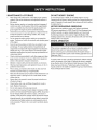 5
5
-
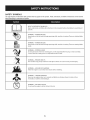 6
6
-
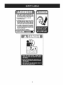 7
7
-
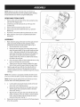 8
8
-
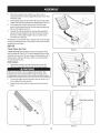 9
9
-
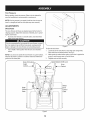 10
10
-
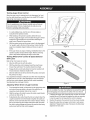 11
11
-
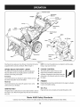 12
12
-
 13
13
-
 14
14
-
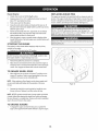 15
15
-
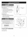 16
16
-
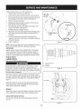 17
17
-
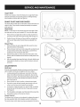 18
18
-
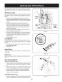 19
19
-
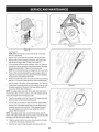 20
20
-
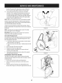 21
21
-
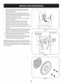 22
22
-
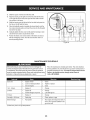 23
23
-
 24
24
-
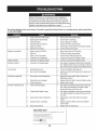 25
25
-
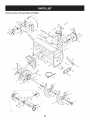 26
26
-
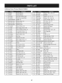 27
27
-
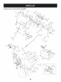 28
28
-
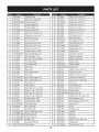 29
29
-
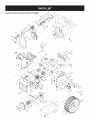 30
30
-
 31
31
-
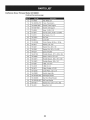 32
32
-
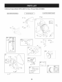 33
33
-
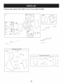 34
34
-
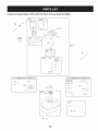 35
35
-
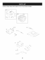 36
36
-
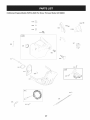 37
37
-
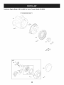 38
38
-
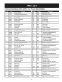 39
39
-
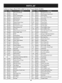 40
40
-
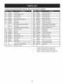 41
41
-
 42
42
-
 43
43
-
 44
44
-
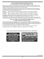 45
45
-
 46
46
-
 47
47
-
 48
48
-
 49
49
-
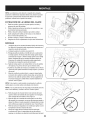 50
50
-
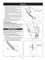 51
51
-
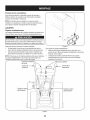 52
52
-
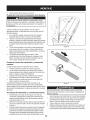 53
53
-
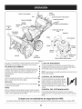 54
54
-
 55
55
-
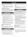 56
56
-
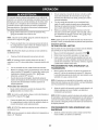 57
57
-
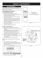 58
58
-
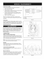 59
59
-
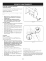 60
60
-
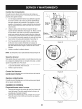 61
61
-
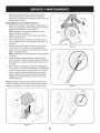 62
62
-
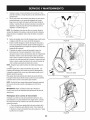 63
63
-
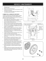 64
64
-
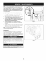 65
65
-
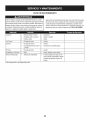 66
66
-
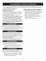 67
67
-
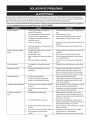 68
68
-
 69
69
-
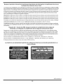 70
70
-
 71
71
-
 72
72


Craftsman 247.88833 El manual del propietario
- Categoría
- Lanzadores de nieve
- Tipo
- El manual del propietario
- Este manual también es adecuado para
en otros idiomas
- English: Craftsman 247.88833 Owner's manual
Artículos relacionados
-
Craftsman 247.88173 series Manual de usuario
-
MTD 247889550 El manual del propietario
-
-
-
-
-
-
-
-