Kichler Lighting 49551AZLED Manual de usuario
- Tipo
- Manual de usuario

Date Issued: 6/12/15
IS-49550LED-US
We’re here to help 866-558-5706
Hrs: M-F 9am to 5pm EST
WARNING:
• This fixture is intended for installation in accordance with the National Electric Code
(NEC) and all local code specifications.
• Supply wires are not intended for use through or concealed behind walls, floors, or
ceilings.
• The LED light output is strong enough to injure human eyes. Precautions must be
taken to prevent looking directly at LED’s with unaided eyes for more than a few
seconds.
DIMMING: This LED fixture is compatible with most standard incandescent dimmers and
LED dimmers.
1) Read and understand all instructions and illustrations completely before proceeding
with assembly and installation of fixture.
2) If you have any doubts about how to install this fixture, or if the fixture fails to
operate completely, please contact a qualified electrician.
3) All parts must be used as indicated in the instructions. Do not substitute any parts,
leave parts out, or use any parts that are worn or broken. Failure to obey this
instruction could invalidate the UL listing, C.S.A. certification, and/or ETL listing of
this fixture.
1) TURN OFF POWER.
IMPORTANT: Before you start, NEVER attempt any work without shutting off the
electricity until the work is done.
a) Go to the main fuse, or circuit breaker, box in your home. Place the main power
switch in the “OFF” position.
b) Unscrew the fuse(s), or switch “OFF” the circuit breaker switch(s), that control
the power to the fixture or room that you are working on.
c) Place the wall switch in the “OFF” position. If the fixture to be replaced has a
switch or pull chain, place those in the “OFF” position.
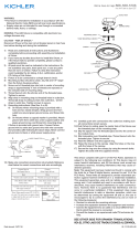
2) Find the appropriate threaded holes on mounting strap. Assemble mounting screws
into threaded holes.
3) Attach mounting strap to outlet box. Mounting strap can be adjusted to suit position
of fixture.
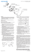
4) Grounding instructions: (See Illus. A or B).
A) On fixtures where mounting strap is provided with a hole and two raise dimples.
Wrap ground wire from outlet box around green ground screw, and thread into
hole.
B) On fixtures where a cupped washer is provided. Put ground wire from outlet box
under cupped washer and green ground screw and thread screw into hole in
mounting strap.
If fixture is provided with ground wire. Connect fixture ground wire to outlet box
ground wire with wire connector, (not provided) after following the above steps.
Never connect ground wire to black or white power supply wires.
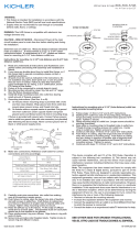
5) Make wire connections. Reference chart below for correct connections and wire
accordingly.
6) Mounting surface should be clean, dry, flat and 1/4” larger than the fixture housing
surface.
7) Any gaps in the mounting surface exceeding 3/16” should be corrected as required.
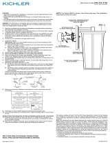
8) Place back plate over mounting strap. Care must be taken not to pinch supply wires.
9) Place star washers onto fixture mounting screws.
10) Screw ball knobs onto fixture mounting screws.
11) Install housing onto back plate. Secure using two #8 flat head screws provided.
12) With silicone RTV caulk, caulk completely around the housing/wall joint on the top
and both sides. Caulk should not be applied to the bottom joint (see figure 2).
GREEN GROUND
SCREW
CUPPED
WASHER
A
B
OUTLET BOX
GROUND
FIXTURE
GROUND
DIMPLES
WIRE CONNECTOR
(NOT PROVIDED)
OUTLET BOX
GROUND
GREEN GROUND
SCREW
FIXTURE
GROUND
Connect Black or
Red Supply Wire to:
Connect
White Supply Wire to:
Black White
*Parallel cord (round & smooth)
*Parallel cord (square & ridged)
Clear, Brown, Gold or Black
without tracer
Clear, Brown, Gold or Black
with tracer
Insulated wire (other than green)
with copper conductor
Insulated wire (other than green)
with silver conductor
*Note: When parallel wires (SPT I & SPT II)
are used. The neutral wire is square shaped
or ridged and the other wire will be round in
shape or smooth (see illus.)
Neutral Wire
This device complies with part 15 of the FCC Rules. Operation is subject to the following
two conditions: (1) This device may not cause harmful interference, and (2) this device
must accept any interference received, including interference that may cause undesired
operation.
Note: This equipment has been tested and found to comply with the limits for a Class B
digital device, pursuant to part 15 of the FCC Rules. These limits are designed to pro-
vide reasonable protection against harmful interference in a residential installation. This
equipment generates, uses and can radiate radio frequency energy and, if not installed
and used in accordance with the instructions, may cause harmful interference to radio
communications. However, there is no guarantee that interference will not occur in a par-
ticular installation. If this equipment does cause harmful interference to radio or television
reception, which can be determined by turning the equipment off and on, the user is
encouraged to try to correct the interference by one or more of the following measures:
• Reorient or relocate the receiving antenna.
• Increase the separation between the equipment and receiver.
• Connect the equipment into an outlet on a circuit different from that to which the receiver
is connected.
• Consult the dealer or an experienced radio/TV technician for help.
SIDE VIEW
TOP VIEW
MOUNTING SCREW
HOUSING
MOUNTING STRAP
BACK PLATE
SIDE VIEW
TOP VIEW
SECTION VIEW TO
SHOW FIXTURE ORIENTATION.
FIXTURE IS TO BE ORIENTED
WITH GLASS ON TOP.
WALL
SILICONE RTV CAULK ON
TOP JOINT AND BOTH
VERTICAL JOINTS.
SEE STEP #12
FIGURE 2
BALL KNOB
STAR WASHER
HOUSING
BACK PLATE
MOUNTING SCREW
HOUSING
MOUNTING STRAP
BACK PLATE
BALL KNOB
STAR WASHER
HOUSING
BACK PLATE
49550 LED
49551 LED

Date Issued: 6/12/15
IS-49550LED-US
We’re here to help 866-558-5706
Hrs: M-F 9am to 5pm EST
Este artefacto cumple con la parte 15 de las Normas de la FCC. El funcionamiento está
sujeto a las siguientes dos condiciones: (1) Este artefacto no puede causar interferencia
perjudicial, y (2) este artefacto debe aceptar cualquier interferencia recibida, inclusive
interferencia que puede causar una operación no deseada.
Nota: Este equipo ha sido probado y se comprobó que cumple con los límites para un
artefacto digital Clase B, de conformidad con la parte 15 de las Normas de la FCC. Estos
límites están diseñados para proporcionar una protección razonable contra interferencia
perjudicial en una instalación residencial. Este equipo genera, usa y puede radiar energía
de radio frecuencia y, si no se instala y usa de acuerdo con las instrucciones, puede cau-
sar interferencia perjudicial las comunicaciones de radio. Sin embargo, no hay garantía
que la interferencia no ocurrirá en una instalación en particular. Si este equipo sí causa
interferencia perjudicial a la recepción de radio o televisión, que puede ser determinado
enciendo y apagando el equipo, se alienta al usuario a que trata de corregir la interferen-
cia con una o más de las siguientes medidas:
• Reoriente o cambie de lugar la antena de recepción.
• Aumente la separación entre el equipo y el receptor.
• Conecte el equipo en un receptáculo en un circuito diferente de donde está conectado
el receptor.
• Consulte al distribuidor o a un técnico de radio/TV experimentado para ayuda.
VISTA LATERAL
VISTA SUPERIOR
TORNILLO DE MONTAJE
CUBIERTA
CORREA DE MONTAJE
PLACA TRASERA
VISTA LATERAL
VISTA SUPERIOR
LA VISTA EN SECCIÓN QUE MUESTRA LA
ORIENTACIÓN DEL ARTEFACTO.
EL ARTEFACTO DEBE SER ORIENTADO CON EL
VIDRIO EN LA PARTE SUPERIOR.
PARED
MASILLA RTV DE SILICÓN
SOBRE LA JUNTA SUPERIOR
Y AMBAS JUNTAS VERTICALES.
VEA EL PASO #12
FIGURA 2
PERILLA
REDONDA
ARANDELA
ESTRELLA
CUBIERTA
PLACA TRASERA
TORNILLO DE MONTAJE
CUBIERTA
CORREA DE MONTAJE
PLACA TRASERA
PERILLA REDONDA
ARANDELA
ESTRELLA
CUBIERTA
PLACA TRASERA
49550 LED
49551 LED
ADVERTENCIA:
• Este artefacto está hecho para ser instalado de acuerdo con el Código Nacional de
Electricidad (NEC) y todas las especificaciones del código local.
• Los alambres suministrados no tienen el propósito de ser utilizados a través de o es
condidos detrás de paredes, pisos o techos.
• La salida de luz del LED es lo suficientemente fuerte para lesionar los ojos humanos.
Deben tomarse precauciones para evitar mirar directamente con los ojos sin protección
durante poco más de unos cuantos segundos.
OSCURECIMIENTO: Este artefacto de LED es compatible con la mayoría de los regula-
dores de intensidad estándares y los reguladores de intensidad de LED.
1) Lea y entienda completamente todas las instrucciones e ilustraciones antes de proceder
con el ensamblaje e instalación del artefacto.
2) Si usted tiene dudas sobre como instalar este artefacto, o si el artefacto no funciona
completamente, por favor contacte a un electricista calificado.
3) Todas las partes deben ser utilizadas tal como se indica en las instrucciones. No
sustituya ninguna de las partes, deje fuera algunas partes, o utilice cualquier parte
que esté desgastada o rota. El no obedecer esta instrucción podría invalidar el listado
en UL, la certificación de C.S.A. y/o el listado en ETL de este artefacto.
1) APAGAR LA ALIMENTACIÓN DE ENERGIE ELÈTRICA.
IMPORTANTE: Antes de comenzar, NUNCA trate de trabajar sin antes desconectar
la corriente hasta que el trabajo se termine.
a) Vaya a la caja principal de fusibles, o interruptor o caja de circuitos de su casa.
Coloque el interruptor de la corriente principal en posición de apagado “OFF”.
b) Desatornille el (los) fusible (s), o coloque el interruptor o interruptores del breaker en
posición de apagado “OFF”, que controla (n) la corriente hacia el artefacto o
habitación donde está trabajando.
c) Coloque el interruptor de pared en posición de apagado “OFF”. Si el artefacto
que se va a reemplazar tiene un interruptor o cadena que se jala, colóquelos en
la posición de apagado “OFF”.
2) Encuentre los agujeros roscados apropiados sobre la correa de montaje. Ensamble
los tornillos de montaje en los agujeros roscados.
3) Fije la correa de montaje a la caja de salida. La correa de montaje puede ser ajustada
para adaptarse a la posición del artefacto.
4) Instrucciones de conexión a tierra solamente para los Estados Unidos. (Vea la
ilustracion A o B).
A) En las lámparas que tienen el fleje, de montaje con un agujero y dos hoyuelos
realzados. Enrollar el alambre a tierra de la caja tomacorriente alrededor del tornillo
verde y pasarlo por el aquiero.
B) En las lámparas con una arandela acopada. Fijar el alambre a tierra de la caja
tomacorriente del ajo de la arandela acoada y tornillo verde, y paser por el fleje
de montaje.
Si la lámpara viene con alambre a tierra. Conecter el alambre a tierra de la lámpara
al alambre a tierra de la caja tomacorriente con un conector de alambres. (No
incluido) Espués de seguir los pasos anteriores. Nunca conectar el alambra a tierra
a los alambres eléctros negro o blanco.
5) Haga les conexiones de los alambres (no se proveen los connectores.) La tabla de
referencia de abajo indica las conexiones correctas y los alambres correspondientes.
6) La superficie de montaje deberá estar limpia, seca, plana y ¼” más larga que la
superficie de la cubierta del artefacto.
7) Cualquier espacio libre en la superficie de montaje que exceda 3/16” deberá ser
corregido según sea requerido.
8) Coloque la placa trasera sobre la correa de montaje. Debe tenerse cuidado para no
pellizcar los alambres de suministro.
9) Coloque las arandelas estrella sobre los tornillos de montaje del artefacto.
10) Atornille las perillas redondas sobre los tornillos de montaje del artefacto.
11) Instale la cubierta sobre la placa trasera. Asegúrela utilizando dos tornillos de cabeza
plana #8 provistos.
12) Con masilla RTV de silicón, calafatee completamente alrededor de la junta de la
cubierta / pared en la parte superior y ambos costados. La masilla no deberá ser
aplicada a la junta inferior (vea la figura 2).
Conectar el alambre de
suministro negro o rojo al
Conectar el alambre de
suministro blanco al
Negro Blanco
*Cordon paralelo (redondo y liso)
*Cordon paralelo (cuadrado y estriado)
Claro, marrón, amarillio o negro
sin hebra identificadora
Claro, marrón, amarillio o negro
con hebra identificadora
Alambre aislado (diferente del verde)
con conductor de cobre
Alambre aislado (diferente del
verde) con conductor de plata
*Nota: Cuando se utiliza alambre paralelo
(SPT I y SPT II). El alambre neutro es de forma
cuadrada o estriada y el otro alambre será de
forma redonda o lisa. (Vea la ilustracíón).
Hilo Neutral
ARANDELA
CONCAVA
A
B
TIERRA DE LA
CAJA DE SALIDA
TORNILLO DE TIERRA,
VERDE
DEPRESIONES
TIERRA
ARTEFACTO
CONECTOR DE ALAMBRE
(NO SE PROVEE)
TIERRA DE LA
CAJA DE SALIDA
TORNILLO DE TIERRA,
VERDE
TIERRA
ARTEFACTO
-
 1
1
-
 2
2