LD Systems Stinger 12A G3 12″ Powered Speaker Manual de usuario
- Tipo
- Manual de usuario

USER´S MANUAL
BEDIENUNGSANLEITUNG
MANUEL D´UTILISATION
MANUAL DE USUARIO
INSTRUKCJA OBSŁUGI
MANUALE D´USO
STINGER
®
G3 INSTALLATION KITS

CONTENTS / INHALTSVERZEICHNIS / CONTENU / CONTENIDO / TREŚĆ / CONTENUTO
ENGLISH
PREVENTIVE MEASURES 3-4
OVERVIEW 5-16
TECHNICAL DATA 17-18
MANUFACTURER’S DECLARATIONS 18
DEUTSCH
SICHERHEITSHINWEISE 19-20
ÜBERSICHT 21-32
TECHNISCHE DATEN 33-34
HERSTELLERERKLÄRUNGEN 34
FRANCAIS
MESURES PRÉVENTIVES 35-36
VUE D‘ENSEMBLE 37-47
CARACTÉRISTIQUES TECHNIQUES 47-49
DÉCLARATIONS DU FABRICANT 49
ESPAÑOL
MEDIDAS DE SEGURIDAD 50-51
VISTA GENERAL 52-63
DATOS TÉCNICOS 64-65
DECLARACIONES DEL FABRICANTE 66
POLSKI
ŚRODKI OSTROŻNOŚCI 66-67
PRZEGLĄD 68-79
DANE TECHNICZNE 80-81
OŚWIADCZENIA PRODUCENTA 81
ITALIANO
MISURE PRECAUZIONALI 82-83
PANORAMICA 84-95
DATI TECNICI 96-97
DICHIARAZIONI DEL PRODUTTORE 97

3
DEUTSCHFRANCAIS
ESPAÑOL
ENGLISH
ITALIANO POLSKI
ENGLISH
YOU‘VE MADE THE RIGHT CHOICE!
We have designed this product to operate reliably over many years. LD Systems stands for this with its name and many years of experience as
a manufacturer of high-quality audio products. Please read this User‘s Manual carefully, so that you can begin making optimum use of your LD
Systems product quickly.
You can nd more information about LD-SYSTEMS at our Internet site WWW.LD-SYSTEMS.COM
PREVENTIVE MEASURES
1. Please read these instructions carefully.
2. Keep all information and instructions in a safe place.
3. Follow the instructions.
4. Observe all safety warnings. Never remove safety warnings or other information from the equipment.
5. Use the equipment only in the intended manner and for the intended purpose.
6. Use only sufciently stable and compatible stands and/or mounts (for xed installations). Make certain that wall mounts are properly installed and
secured. Make certain that the equipment is installed securely and cannot fall down.
7. During installation, observ e the applicable safety regulations for your country.
8. Never install and operate the equipment near radiators, heat registers, ovens or other sources of heat. Make certain that the equipment is always installed
so that is cooled sufciently and cannot overheat.
9. Never place sources of ignition, e.g., burning candles, on the equipment.
10. Ventilation slits must not be blocked.
11. Keep a minimum distance of 20 cm around and above the device.
12. Do not use this equipment in the immediate vicinity of water (does not apply to special outdoor equipment - in this case, observe the special
instructions noted below. Do not expose this equipment to ammable materials, uids or gases. Avoid direct sunlight!
13. Make certain that dripping or splashed water cannot enter the equipment. Do not place containers lled with liquids, such as vases or drinking
vessels, on the equipment.
14. Make certain that objects cannot fall into the device.
15. Use this equipment only with the accessories recommended and intended by the manufacturer.
16. Do not open or modify this equipment.
17. After connecting the equipment, check all cables in order to prevent damage or accidents, e.g., due to tripping hazards.
18. During transport, make certain that the equipment cannot fall down and possibly cause property damage and personal injuries.
19. If your equipment is no longer functioning properly, if uids or objects have gotten inside the equipment or if it has been damaged in anot her way,
switch it off immediately and unplug it from the mains outlet (if it is a powered device). This equipment may only be repaired by authorized, qualied
personnel.
20. Clean the equipment using a dry cloth.
21. Comply with all applicable disposal laws in your country. During disposal of packaging, please separate plastic and paper/cardboard.
22. Plastic bags must be kept out of reach of children.
23. Please note that changes or modications not expressly approved by the party responsible for compliance could void the user´s authority to
operate the equipment.
FOR EQUIPMENT THAT CONNECTS TO THE POWER MAINS
24. CAUTION: If the power cord of the device is equipped with an earthing contact, then it must be connected to an outlet with a protective ground.
Never deactivate the protective ground of a power cord.
25. If the equipment has been exposed to strong uctuations in temperature (for example, after transport), do not switch it on immediately. Mois-
ture and condensation could damage the equipment. Do not switch on the equipment until it has reached room temperature.
26. Before connecting the equipment to the power outlet, rst verify that the mains voltage and frequency match the values specied on the equip-
ment. If the equipment has a voltage selection switch, connect the equipment to the power outlet only if the equipment values and the mains
power values match. If the included power cord or power adapter does not t in your wall outlet, contact your electrician.
27. Do not step on the power cord. Make certain that the power cable does not become kinked, especially at the mains outlet and/or power adapter
and the equipment connector.
28. When connecting the equipment, make certain that the power cord or power adapter is always freely accessible. Always disconnect the equip-
ment from the power supply if the equipment is not in use or if you want to clean the equipment. Always unplug the power cord and power adapter
from the power outlet at the plug or adapter and not by pulling on the cord. Never touch the power cord and power adapter with wet hands.
29. Whenever possible, avoid switching the equipment on and off in quick succession because otherwise this can shorten the useful life of the
equipment.
30. IMPORTANT INFORMATION: Replace fuses only with fuses of the same type and rating. If a fuse blows repeatedly, please contact an authorised
service centre.
31. To disconnect the equipment from the power mains completely, unplug the power cord or power adapter from the power outlet.
32. If your device is equipped with a Volex power connector, the mating Volex equipment connector must be unlocked before it can be removed. Howe-
ver, this also means that the equipment can slide and fall down if the power cable is pulled, which can lead to personal injuries and/or other damage.
For this reason, always be careful when laying cables.
33. Unplug the power cord and power adapter from the power outlet if there is a risk of a lightning strike or before extended periods of disuse.

4
ITALIANO
POLSKI
ESPAÑOL
FRANCAIS
DEUTSCHENGLISH
CAUTION:
To reduce the risk of electric shock, do not remove cover (or back). There are no user serviceable
parts inside. Maintenance and repairs should be exclusively carried out by qualied service
personnel.
The warning triangle with lightning symbol indicates dangerous uninsulated voltage inside the unit, which may cause an
electrical shock.
The warning triangle with exclamation mark indicates important operating and maintenance instructions.
Warning! This symbol indicates a hot surface. Certain parts of the housing can become hot during operation. After use, wait for
a cool-down period of at least 10 minutes before handling or transporting the device.
Warning! This device is designed for use below 2000 metres in altitude.
Warning! This product is not intended for use in tropical climates.
CAUTION! HIGH VOLUMES IN AUDIO PRODUCTS!
This device is meant for professional use. Therefore, commercial use of this equipment is subject to the respectively applicable national accident
prevention rules and regulations. As a manufacturer, Adam Hall is obligated to notify you formally about the existence of potential health risks.
Hearing damage due to high volume and prolonged exposure: When in use, this product is capable of producing high sound-pressure levels (SPL)
that can lead to irreversible hearing damage in performers, employees, and audience members. For this reason, avoid prolonged exposure to
volumes in excess of 90 dB.
NOTE: This equipment has been tested and found to comply with the limits for a Class B digital device, pursuant to Part 15 of the FCC
Rules. These limits are designed to provide reasonable protection against harmful interference in a residential installation. This equipment
generates, uses and can radiate radio frequency energy and, if not installed and used in accordance with the instructions, may cause
harmful interference to radio communications. However, there is no guarantee that interference will not occur in a particular installation. If
this equipment does cause harmful interference to radio or television reception, which can be determined by turning the equipment off and
on, the user is encouraged to try to correct the interference by one or more of the following measures:
- Reorient or relocate the receiving antenna.
- Increase the separation between the equipment and receiver.
- Connect the equipment into an outlet on a circuit different from that to which the receiver is connected.
- Consult the dealer or an experienced radio/TV technician for help.
Important: Before any assembly, check that all installation kit components are complete, undamaged and work correctly (split pins, screws, bolts, nuts,
locking pins, steel hooks, retaining sockets and threads in speakers, etc.). Should any installation kit component be damaged, missing or not function
properly, the installation kit should not be used.
An M8 thread is situated on the rear side of the speaker for the installation of a secondary safety component.

5
DEUTSCHFRANCAIS
ESPAÑOL
ENGLISH
ITALIANO POLSKI
OVERVIEW
Product number Suitable for Installation Type
LDEB82G3WMB LDEB82G3 LDEB82AG3
Wall & ceiling
LDEB102G3WMB LDEB102G3 LDEB102AG3
LDEB282G3WMB LDEB282G3 LDEB282AG3
LDEBG3WMB
LDEB122G3 LDEB122AG3
Wall
LDEB152G3 LDEB152AG3
LDEB82G3WMB1 LDEB82G3 Wall
LDEB82AG3WMB1 LDEB82AG3 Wall
&
GSPWMBS30B LDEB282G3 Wall
LDEB282AG3WMB1 LDEB282AG3 Wall &
LDEB102G3WMB1 LDEB102G3 LDEB102AG3 Wall
LDEBG3WMB1
LDEB122G3 LDEB122AG3
Wall
LDEB152G3 LDEB152AG3
LDEBG3TMB
LDEB122G3 LDEB122AG3
Truss
LDEB152G3 LDEB152AG3
LDEBG3SCP
LDEB82G3 LDEB82AG3
Truss
LDEB102G3 LDEB102AG3

6
ITALIANO
POLSKI
ESPAÑOL
FRANCAIS
DEUTSCHENGLISH
C
A
B
A
LDEB82G3WMB (suitable for LDEB82G3, LDEB82AG3)
LDEB102G3WMB (suitable for LDEB102G3, LDEB102AG3)
LDEB282G3WMB (suitable for LDEB282G3, LDEB282AG3)
Screw the U-bracket of the desired Stinger G3 speaker in a suitable position to a load-bearing wall or ceiling (A). Use suitable screws and plugs etc. to ensure
secure mounting. Remove the M8 screws on the top and bottom of the speaker and lift the speaker into the bracket so that the thread locations in the
speaker and the holes in the bracket are aligned. Use the supplied M8 screws and washers as shown in the gure below (B, place rubber washers between
the bracket and the speaker), adjust dispersion angle as desired and tighten the screws with a suitable tool (C).

7
DEUTSCHFRANCAIS
ESPAÑOL
ENGLISH
ITALIANO POLSKI
A
F
A
F
D
C
E
B
LDEBG3WMB (suitable for LDEB122G3, LDEB122AG3, LDEB152G3, LDEB152AG3)
Screw the adjustable U-bracket (in a suitable position) to a load-bearing wall (A). Use suitable screws and plugs etc. to ensure secure mounting. The
35mm mounting stud can be installed on the bracket at four different distances from the wall. Select the appropriate position for the speaker and
screw it tightly to the bracket (B, position the supplied rubber ring on the mounting stud). Remove the M10 screw on the top of the loudspeaker and lift
the speaker into the bracket so that the 35mm mounting stud sits in the 0° ange of the speaker (C). Now set the adjustable side of the bracket to the
appropriate size for the speaker and secure it with the two screws on the side of the bracket (D). Using the supplied M10 T-screw in the correct position
directly opposite the mounting stud, position the speaker at the desired angle in the bracket (E, place supplied rubber washer between bracket and
speaker. For permanent installation an M10 Allen screw is supplied).

8
ITALIANO
POLSKI
ESPAÑOL
FRANCAIS
DEUTSCHENGLISH
A
LDEB82G3WMB1 (suitable for LDEB82G3)
1. Remove the two M6 screws A on the back of the speaker.
2. Slightly loosen bolt E on the wall bracket (do not remove), loosen and remove bolt D from the tilt & swivel arm, remove it and lift the U-bracket B
from its mounting. Attach the U-bracket B to the rear of the speaker with the supplied screws.
3. Using screws, attach mounting plate C vertically in a suitable position to a solid wall with its at side and safety eyelet facing upwards (4 screws).
Use suitable screws and plugs etc. to ensure secure mounting.
4. Now slide the speaker with the attached U-bracket B into the bracket on the wall, reinstall bolt D into its designated position and secure it with
the previously removed nut.
5. The speaker can be tilted vertically by slightly loosening nut E, adjusting to the desired angle and then re-tightening the nut. The speaker can be
adjusted horizontally by loosening nut F (remove plastic cap beforehand), adjusting the angle as required, and then re-tightening the nut.
A
LDEB82AG3WMB1 (suitable for LDEB82AG3)
1. Remove four M4 screws A on the back of the speaker in the positions for fastening the adapter plate. Ensure that the cutouts for the LINE OUT
jack and POWER switch are correctly positioned. Attach the adapter plate to the speaker with the supplied M4 screws so that the LINE OUT jack and
POWER switch are freely accessible.
2. Slightly loosen bolt E on the wall bracket (do not remove), loosen and remove bolt D from the tilt & swivel arm, remove it and lift the U-bracket B
from its mounting. Attach the U-bracket B to the rear of the adapter plate with the supplied nuts.
3. Using screws, attach mounting plate C vertically in a suitable position to a solid wall with its at side and safety eyelet facing upwards (4 screws).
Use suitable screws and plugs etc. to ensure secure mounting.
4. Now slide the speaker with the attached U-bracket B into the bracket on the wall, reinstall bolt D into its designated position and secure it with
the previously removed nut.
5. The speaker can be tilted vertically by slightly loosening nut E, adjusting to the desired angle and then re-tightening the nut. The speaker can be
adjusted horizontally by loosening nut F (remove plastic cap beforehand), adjusting the angle as required, and then re-tightening the nut.

9
DEUTSCHFRANCAIS
ESPAÑOL
ENGLISH
ITALIANO POLSKI
B
D
E
F
C
GSPWMBS30B (suitable for LDEB282G3)
1. Remove the four M6 screws A on the back of the speaker.
2. Slightly loosen bolt E of the wall bracket (do not remove), loosen and remove bolt D from the tilt & swivel arm, remove and lift the U-bracket with
mounting plate B from its mounting. Attach the U-bracket with mounting plate B to the rear of the speaker with the supplied screws.
3. Using screws, attach mounting plate C vertically in a suitable position to a solid wall with its at side and safety eyelet facing upwards (8 screws).
Use suitable screws and plugs etc. to ensure secure mounting.
4. Now slide the speaker with the attached U-bracket with mounting plate B into the bracket on the wall, reinstall bolt D into its designated position
and secure it with the previously removed nut.
5. The speaker can be tilted vertically by slightly loosening nut E, adjusting to the desired angle and then re-tightening the nut. The speaker can be
adjusted horizontally by loosening nut F (remove plastic cap beforehand), adjusting the angle as required, and then re-tightening the nut.

10
ITALIANO
POLSKI
ESPAÑOL
FRANCAIS
DEUTSCHENGLISH
E
D
B
F
A
LDEB282AG3WMB1 (suitable for LDEB282AG3)
1. Remove six M4 screws A on the back of the speaker in the positions for fastening the adapter plate. Ensure that the cutouts for the LINE OUT
jack and POWER switch are correctly positioned. Attach the adapter plate to the speaker with the supplied M4 screws so that the LINE OUT jack and
POWER switch are freely accessible.
2. Slightly loosen bolt E on the wall bracket (do not remove), loosen and remove bolt D from the tilt & swivel arm, remove it and lift the U-bracket B
from its mounting. Attach the U-bracket B to the rear of the adapter plate with the supplied nuts.
3. Using screws, attach mounting plate C vertically in a suitable position to a solid wall with its at side and safety eyelet facing upwards (8 screws).
Use suitable screws and plugs etc. to ensure secure mounting.
4. Now slide the speaker with the attached U-bracket B into the bracket on the wall, reinstall bolt D into its designated position and secure it with
the previously removed nut.
5. The speaker can be tilted vertically by slightly loosening nut E, adjusting to the desired angle and then re-tightening the nut. The speaker can be
adjusted horizontally by loosening nut F (remove plastic cap beforehand), adjusting the angle as required, and then re-tightening the nut.

11
DEUTSCHFRANCAIS
ESPAÑOL
ENGLISH
ITALIANO POLSKI
A
A
C
E
D
F
B
LDEB102G3WMB1 (suitable for LDEB102G3, LDEB102AG3)
1. Remove the four M6 screws A on the back of the speaker.
2. Slightly loosen bolt E of the wall bracket (do not remove), loosen and remove bolt D from the tilt & swivel arm, remove and lift the U-bracket with
mounting plate B from its mounting. Attach the U-bracket with mounting plate B to the rear of the speaker with the supplied screws.
3. Using screws, attach mounting plate C vertically in a suitable position to a solid wall with its at side and safety eyelet facing upwards (4 screws).
Use suitable screws and plugs etc. to ensure secure mounting.
4. Now slide the speaker with the attached U-bracket with mounting plate B into the bracket on the wall, reinstall bolt D into its designated position
and secure it with the previously removed nut.
5. The speaker can be tilted vertically by slightly loosening nut E, adjusting to the desired angle and then re-tightening the nut. The speaker can be
adjusted horizontally by loosening nut F (remove plastic cap beforehand), adjusting the angle as required, and then re-tightening the nut.

12
ITALIANO
POLSKI
ESPAÑOL
FRANCAIS
DEUTSCHENGLISH
A
A
C
E
D
B
F
LDEBG3WMB1 (suitable for LDEB122G3, LDEB122AG3, LDEB152G3, LDEB152AG3)
1. Remove the four M6 screws A on the back of the speaker.
2. Slightly loosen bolt E of the wall bracket (do not remove), loosen and remove bolt D from the tilt & swivel arm, remove and lift the U-bracket with
mounting plate B from its mounting. Attach the U-bracket with mounting plate B to the rear of the speaker with the supplied screws.
3. Using screws, attach mounting plate C vertically in a suitable position to a solid wall with its at side and safety eyelet facing upwards (8 screws).
Use suitable screws and plugs etc. to ensure secure mounting.
4. Now slide the speaker with the attached U-bracket with mounting plate B into the bracket on the wall, reinstall bolt D into its designated position
and secure it with the previously removed nut.
5. The speaker can be tilted vertically by slightly loosening nut E, adjusting to the desired angle and then re-tightening the nut. The speaker can be
adjusted horizontally by loosening nut F (remove plastic cap beforehand), adjusting the angle as required, and then re-tightening the nut.

13
DEUTSCHFRANCAIS
ESPAÑOL
ENGLISH
ITALIANO POLSKI
LDEBG3TMB (suitable for LDEB122G3, LDEB122AG3, LDEB152G3, LDEB152AG3)
H
I
E
G
F
D
B
C
A
J
ASSEMBLY OF THE MOUNTING BRACKET AND TRAVERSE CLAMP
1. Release the safety splint (A) from the two M8 screws (B, C) in the cylindrical pivot/tilt head (D) of the mounting bracket.
2. Unscrew the two screws (B, C) from the pivot/tilt head (D), separate the two cylinder halves and remove the cast piece (E).
3. Now use the parts included – the M10 screw (F), spring washer (G) and self-locking M10 nut (H) – to attach the cast piece (E) rmly to the traverse
clamp (I) using a 17 mm socket tool. To do so, place the traverse clamp in the recess of the cast piece and the self-locking nut in the recess of the
traverse clamp and then insert the screw with the spring washer through the cast piece into the traverse clamp (see illustration).
4. Now place the cast piece with the traverse clamp into one half of the pivot/tilt head (D) and join the two halves in such a way that the M8 screw
(C) can be placed through the appropriate installation hole of the one half, through the support rail (J) of the mounting bracket and through the
installation hole of the cylindrical pivot/tilt head. Place the previously removed washer on the screw and nger tighten the M8 nut. Secure the nut
using the previously released safety splint (A).
5. Put the M8 washer onto the M8 lever screw (B), taking care to ensure that the M8 nut is correctly placed in the recess of the appropriate cylinder
half of the pivot/tilt head. Insert the lever screw through the two cylinder halves and tighten. Secure the screw using a previously released safety
splint (A).

14
ITALIANO
POLSKI
ESPAÑOL
FRANCAIS
DEUTSCHENGLISH
2
3
9
9
5
4
9
6
1
7
8
8
7
7
PARTS DESCRIPTION AND INSTALLATION
1
Traverse clamp for mounting on a horizontal traverse.
2
Wing nut for clamping to a traverse.
3
T-screw to lock the horizontal and vertical axes
4
Mounting rail with slots to adjust the vertical dispersion of the speaker.
5
Retaining pin.
6
Rotation mechanism for adjusting the horizontal dispersion of the speaker.
7
Three steel hooks which insert into the retaining sockets on the top of the speaker.
8
Two spring-loaded locking pins to secure the connection.
9
Mounting holes for alternative installation of the speaker with chains.
Important: Before any assembly, check that all mounting bracket components are complete, undamaged and work correctly (split pins, screws,
bolts, nuts, locking pins, steel hooks, retaining sockets in speakers, etc.). Should any mounting bracket component be damaged, missing or not
function properly, the mounting bracket should not be used.

15
DEUTSCHFRANCAIS
ESPAÑOL
ENGLISH
ITALIANO POLSKI
10 11 12
13 14 15
10
Insert all three steel hooks of the EasyMount bracket into the corresponding retaining sockets on the speaker.
11
Slide the entire bracket towards the back of the speaker.
12
When installing the mounting bracket, ensure that the spring-loaded locking pins engage fully. Ensure that locking pins are functioning
correctly before every installation. For safety reasons, both locking pins must be pulled upwards simultaneously to release the connection
(two-hand release).
13
Before attaching the speaker to a traverse, tighten the T-screw on the mounting bracket No. 3. Using traverse clamp No.1, suspend the speaker
from a horizontal traverse in a suitable position, and fasten it into place with wing nut No. 2.
14
Loosen T-screw No. 3 slightly (approximately 1 turn). To adjust the vertical dispersion of the speaker, lift the speaker slightly and slide the
notched mounting rail No.4 into the desired tilt position. Release the speaker to allow the retaining pin No. 5 to engage in the corresponding notch.
15
Turn the speaker until the desired horizontal dispersion is achieved and tighten T-screw No. 3.

16
ITALIANO
POLSKI
ESPAÑOL
FRANCAIS
DEUTSCHENGLISH
2
3
1
5
4
6
8
7
LDEBG3SCP (suitable for LDEB82G3, LDEB82AG3, LDEB102G3, LDEB102AG3)
1
Traverse clamp with adjustable T-screw and ange for mounting pin (only for mounting on horizontal traverses).
2
Mounting pin with M10 thread and wing nut.
3
Adapter for attaching the clamp to square-section tubes.
4
Remove the M10 screw on the top of the speaker.
5
Remove the M10 wing nut from the mounting pin (No. 2) and screw it fully into the M10 thread on the top of the speaker.
6
Attach the traverse clamp to a traverse with the adjustable T-screw in a suitable position and ensure a rm grip.
7
Loosen the locking screw so far that the ange on the underside of the clamp can accept the mounting pin (do not remove the bolt).
8
Push the spring-loaded locking pins on the side of the clamp into the housing so that the ange on the underside of the clamp can accept the
mounting pin and push the pin all the way into the ange. Release the pressure from the locking pin and keep hold of the speaker until you are
certain that the mounting pin is fully engaged. Rotate the speaker to achieve the desired dispersion and secure the connection by tightening the
locking screw No. 7.

17
DEUTSCHFRANCAIS
ESPAÑOL
ENGLISH
ITALIANO POLSKI
Model name: LDEB82G3WMB LDEB102G3WMB
Type: PA Loudspeaker Accessories PA Loudspeaker Accessories
Part: Wall/Ceiling Mount Bracket Wall/Ceiling Mount Bracket
Suitable for: LDEB82G3, LDEB82AG3 LDEB102G3, LDEB102AG3
Material: Steel Steel
Surface: Powder Coated Powder Coated
Colour: Black Black
Max. Load 12 kg 15 kg
Dimensions (W x H x D): 60 x 460 x 170 mm 60 x 535 x 170 mm
Weight: 1.1 kg 1.2 kg
Model name: LDEB282G3WMB LDEBG3WMB
Type: PA Loudspeaker Accessories PA Loudspeaker Accessories
Part: Wall/Ceiling Mount Bracket Wall Mount Bracket
Suitable for: LDEB282G3, LDEB282AG3 LDEB122G3, LDEB122AG3
LDEB152G3, LDEB152AG3
Material: Steel Steel
Surface: Powder Coated Powder Coated
Colour: Black Black
Max. Load 21 kg 28 kg
Dimensions (W x H x D): 60 x 763 x 170 mm 550 x 90 x 308mm
Weight: 1.5 kg 3.5 kg
Model name: LDEB82G3WMB1 LDEB82AG3WMB1
Type: PA Loudspeaker Accessories PA Loudspeaker Accessories
Part: Wall Mount Bracket Wall Mount Bracket
Suitable for: LDEB82G3 LDEB82AG3
Material: Steel Steel
Surface: Powder Coated Powder Coated
Colour: Black Black
Max. Load 20 kg 11 kg
Dimensions (W x H x D): 100 x 157 x 109mm 130 x 157 x 122mm
Weight: 1.2 kg 2.2 kg
Model name: GSPWMBS30B LDEB282AG3WMB1
Type: PA Loudspeaker Accessories PA Loudspeaker Accessories
Part: Wall Mount Bracket Wall Mount Bracket
Suitable for: LDEB282G3 LDEB282AG3
Material: Steel Steel
Surface: Powder Coated Powder Coated
Colour: Black Black
Max. Load 30 kg 21 kg
Dimensions (W x H x D): 120 x 220 x 160mm 130 x 220 x 173mm
Weight: 1.8 kg 3.3 kg
TECHNICAL DATA

18
ITALIANO
POLSKI
ESPAÑOL
FRANCAIS
DEUTSCHENGLISH
Model name: LDEB102G3WMB1 LDEBG3WMB1
Type: PA Loudspeaker Accessories PA Loudspeaker Accessories
Part: Wall Mount Bracket Wall Mount Bracket
Suitable for: LDEB102G3, LDEB102AG3 LDEB122G3, LDEB122AG3
LDEB152G3, LDEB152AG3
Material: Steel Steel
Surface: Powder Coated Powder Coated
Colour: Black Black
Max. Load 20 kg 30 kg
Dimensions (W x H x D): 100 x 157 x 160mm 120 x 220 x 160mm
Weight: 1.4 kg 1.8 kg
Model name: LDEBG3TMB LDEBG3SCP
Type: PA Loudspeaker Accessories PA Loudspeaker Accessories
Part: Truss Mount Bracket Truss Mount Bracket
Suitable for: LDEB122G3, LDEB122AG3
LDEB152G3, LDEB152AG3
LDEB82G3, LDEB82AG3
LDEB102G3, LDEB102AG3
Material: Steel/Zinc Aluminium/Brass
Surface: Powder Coated Powder Coated/Uncoated
Colour: Black Black/Brass
Max. Load 28 kg 20 kg
Dimensions (W x H x D): 230 x 240 x 430mm 57 x 136 x 118mm
Weight: 3 kg 0.564 kg
MANUFACTURER´S DECLARATIONS
MANUFACTURER‘S WARRANTY & LIMITATIONS OF LIABILITY
You can nd our current warranty conditions and limitations of liability at: https://cdn-shop.adamhall.com/media/pdf/MANUFACTURERS-DECLARATIONS_
LD_SYSTEMS.pdf To request warranty service for a product, please contact Adam Hall GmbH, Adam-Hall-Str. 1,
61267 Neu Anspach / Email: [email protected] / +49 (0)6081 / 9419-0.
CORRECT DISPOSAL OF THIS PRODUCT
(valid in the European Union and other European countries with a differentiated waste collection system)
This symbol on the product, or on its documents indicates that the device may not be treated as household waste. This is to avoid environ-
mental damage or personal injury due to uncontrolled waste disposal. Please dispose of this product separately from other waste and have it
recycled to promote sustainable economic activity. Household users should contact either the retailer where they purchased this product, or their
local government ofce, for details on where and how they can recycle this item in an environmentally friendly manner. Business users should
contact their supplier and check the terms and conditions of the purchase contract. This product should not be mixed with other commercial waste
for disposal.
FCC STATEMENT
This device complies with Part 15 of the FCC Rules. Operation is subject to the following two conditions:
(1) This device may not cause harmful interference, and
(2) This device must accept any interference received, including interference that may cause undesired operation
CE Compliance
Adam Hall GmbH states that this product meets the following guidelines (where applicable):
R&TTE (1999/5/EC) or RED (2014/53/EU) from June 2017
Low voltage directive (2014/35/EU)
EMV directive (2014/30/EU)
RoHS (2011/65/EU)
The complete declaration of conformity can be found at www.adamhall.com.
Furthermore, you may also direct your enquiry to [email protected].

DEUTSCH
SIE HABEN DIE RICHTIGE WAHL GETROFFEN!
Dieses Gerät wurde unter hohen Qualitätsanforderungen entwickelt und gefertigt, um viele Jahre einen reibungslosen Betrieb zu gewährleisten. Dafür
steht LD Systems mit seinem Namen und der langjährigen Erfahrung als Hersteller hochwertiger Audioprodukte. Bitte lesen Sie diese Bedienungsanlei-
tung sorgfältig, damit Sie Ihr neues Produkt von LD Systems schnell optimal einsetzen können.
Mehr Informationen zu LD SYSTEMS nden Sie auf unserer Internetseite WWW.LD-SYSTEMS.COM
SICHERHEITSHINWEISE
1. Lesen Sie diese Anleitung bitte sorgfältig durch.
2. Bewahren Sie alle Informationen und Anleitungen an einem sicheren Ort auf.
3. Befolgen Sie die Anweisungen.
4. Beachten Sie alle Warnhinweise. Entfernen Sie keine Sicherheitshinweise oder andere Informationen vom Gerät.
5. Verwenden Sie das Gerät nur in der vorgesehenen Art und Weise.
6. Verwenden Sie ausschließlich stabile und passende Stative bzw. Befestigungen (bei Festinstallationen). Stellen Sie sicher, dass Wandhalterungen
ordnungsgemäß installiert und gesichert sind. Stellen Sie sicher, dass das Gerät sicher installiert ist und nicht herunterfallen kann.
7. Beachten Sie bei der Installation die für Ihr Land geltenden Sicherheitsvorschriften.
8. Installieren und betreiben Sie das Gerät nicht in der Nähe von Heizkörpern, Wärmespeichern, Öfen oder sonstigen Wärmequellen. Sorgen Sie dafür,
dass das Gerät immer so installiert ist, dass es ausreichend gekühlt wird und nicht überhitzen kann.
9. Platzieren Sie keine Zündquellen wie z.B. brennende Kerzen auf dem Gerät.
10. Lüftungsschlitze dürfen nicht blockiert werden.
11. Halten Sie einen Mindestabstand von 20 cm seitlich und oberhalb des Geräts ein.
12. Betreiben Sie das Gerät nicht in unmittelbarer Nähe von Wasser. Bringen Sie das Gerät nicht mit brennbaren Materialien, Flüssigkeiten oder
Gasen in Berührung. Direkte Sonneneinstrahlung vermeiden!
13. Sorgen Sie dafür, dass kein Tropf- oder Spritzwasser in das Gerät eindringen kann. Stellen Sie keine mit Flüssigkeit gefüllten Behältnisse wie
Vasen oder Trinkgefäße auf das Gerät.
14. Sorgen Sie dafür, dass keine Gegenstände in das Gerät fallen können.
15. Betreiben Sie das Gerät nur mit dem vom Hersteller empfohlenen und vorgesehenen Zubehör.
16. Öffnen Sie das Gerät nicht und verändern Sie es nicht.
17. Überprüfen Sie nach dem Anschluss des Geräts alle Kabelwege, um Schäden oder Unfälle, z. B. durch Stolperfallen zu vermeiden.
18. Achten Sie beim Transport darauf, dass das Gerät nicht herunterfallen und dabei möglicherweise Sach- und Personenschäden verursachen kann.
19. Wenn Ihr Gerät nicht mehr ordnungsgemäß funktioniert, Flüssigkeiten oder Gegenstände in das Geräteinnere gelangt sind, oder das Gerät an-
derweitig beschädigt wurde, schalten Sie es sofort aus und trennen es von der Netzsteckdose (sofern es sich um ein aktives Gerät handelt). Dieses
Gerät darf nur von autorisiertem Fachpersonal repariert werden.
20. Verwenden Sie zur Reinigung des Geräts ein trockenes Tuch.
21. Beachten Sie alle in Ihrem Land geltenden Entsorgungsgesetze. Trennen Sie bei der Entsorgung der Verpackung bitte Kunststoff und Papier bzw.
Kartonagen voneinander.
22. Kunststoffbeutel müssen außer Reichweite von Kindern aufbewahrt werden.
23. Sämtliche vom Benutzer vorgenommenen Änderungen und Modikationen, denen die für die Einhaltung der Richtlinien verantwortliche Partei
nicht ausdrücklich zugestimmt hat, können zum Entzug der Betriebserlaubnis für das Gerät führen.
BEI GERÄTEN MIT NETZANSCHLUSS
24. ACHTUNG: Wenn das Netzkabel des Geräts mit einem Schutzkontakt ausgestattet ist, muss es an einer Steckdose mit Schutzleiter angeschlossen
werden. Deaktivieren Sie niemals den Schutzleiter eines Netzkabels.
25. Schalten Sie das Gerät nicht sofort ein, wenn es starken Temperaturschwankungen ausgesetzt war (beispielsweise nach dem Transport). Feuch-
tigkeit und Kondensat könnten das Gerät beschädigen. Schalten Sie das Gerät erst ein, wenn es Zimmertemperatur erreicht hat.
26. Bevor Sie das Gerät an die Steckdose anschließen, prüfen Sie zuerst, ob die Spannung und die Frequenz des Stromnetzes mit den auf dem Gerät
angegebenen Werten übereinstimmen. Verfügt das Gerät über einen Spannungswahlschalter, schließen Sie das Gerät nur an die Steckdose an,
wenn die Gerätewerte mit den Werten des Stromnetzes übereinstimmen. Wenn das mitgelieferte Netzkabel bzw. der mitgelieferte Netzadapter
nicht in Ihre Netzsteckdose passt, wenden Sie sich an Ihren Elektriker.
27. Treten Sie nicht auf das Netzkabel. Sorgen Sie dafür, dass spannungsführende Kabel speziell an der Netzbuchse bzw. am Netzadapter und der
Gerätebuchse nicht geknickt werden.
28. Achten Sie bei der Verkabelung des Geräts immer darauf, dass das Netzkabel bzw. der Netzadapter stets frei zugänglich ist. Trennen Sie das Gerät
stets von der Stromzuführung, wenn das Gerät nicht benutzt wird, oder Sie das Gerät reinigen möchten. Ziehen Sie Netzkabel und Netzadapter immer am
Stecker bzw. am Adapter und nicht am Kabel aus der Steckdose. Berühren Sie Netzkabel und Netzadapter niemals mit nassen Händen.
29. Schalten Sie das Gerät möglichst nicht schnell hintereinander ein und aus, da sonst die Lebensdauer des Geräts beeinträchtigt werden könnte.
30. WICHTIGER HINWEIS: Ersetzen Sie Sicherungen ausschließlich durch Sicherungen des gleichen Typs und Wertes. Sollte eine Sicherung wiederholt
auslösen, wenden Sie sich bitte an ein autorisiertes Servicezentrum.
31. Um das Gerät vollständig vom Stromnetz zu trennen, entfernen Sie das Netzkabel bzw. den Netzadapter aus der Steckdose.
32. Wenn Ihr Gerät mit einem verriegelbaren Netzanschluss bestückt ist, muss der passende Gerätestecker entsperrt werden, bevor er entfernt werden
kann. Das bedeutet aber auch, dass das Gerät durch ein Ziehen am Netzkabel verrutschen und herunterfallen kann, wodurch Personen verletzt werden
und/oder andere Schäden auftreten können. Verlegen Sie Ihre Kabel daher immer sorgfältig.
33. Entfernen Sie Netzkabel und Netzadapter aus der Steckdose bei Gefahr eines Blitzschlags oder wenn Sie das Gerät länger nicht verwenden.
19
DEUTSCHFRANCAIS
ESPAÑOL
ENGLISH
ITALIANO POLSKI

ACHTUNG
Entfernen Sie niemals die Abdeckung, da sonst das Risiko eines elektrischen Schlages besteht. Im In-
neren des Geräts benden sich keine Teile, die vom Bediener repariert oder gewartet werden können.
Lassen Sie Wartung und Reparaturen ausschließlich von qualiziertem Servicepersonal durchführen.
Das gleichseitige Dreieck mit Blitzsymbol warnt vor nichtisolierten, gefährlichen Spannungen im Geräteinneren, die einen elektrischen
Schlag verursachen können.
Das gleichseitige Dreieck mit Ausrufungszeichen kennzeichnet wichtige Bedienungs- und Wartungshinweise.
Warnung! Dieses Symbol kennzeichnet heiße Oberächen. Während des Betriebs können bestimmte Teile des Gehäuses heiß werden.
Berühren oder transportieren Sie das Gerät nach einem Einsatz erst nach einer Abkühlzeit von mindestens 10 Minuten.
Warnung! Dieses Gerät ist für eine Nutzung bis zu einer Höhe von maximal 2000 Metern über dem Meeresspiegel bestimmt.
Warnung! Dieses Gerät ist nicht für den Einsatz in tropischen Klimazonen bestimmt.
ACHTUNG HOHE LAUTSTÄRKEN BEI AUDIOPRODUKTEN!
Dieses Gerät ist für den professionellen Einsatz vorgesehen. Der kommerzielle Betrieb dieses Geräts unterliegt den jeweils gültigen nationalen
Vorschriften und Richtlinien zur Unfallverhütung. Als Hersteller ist Adam Hall gesetzlich verpichtet, Sie ausdrücklich auf mögliche Gesundheitsrisik-
en hinzuweisen. Gehörschäden durch hohe Lautstärken und Dauerbelastung: Bei der Verwendung dieses Produkts können hohe Schalldruckpegel
(SPL) erzeugt werden, die bei Künstlern, Mitarbeitern und Zuschauern zu irreparablen Gehörschäden führen können. Vermeiden Sie länger anhalten-
de Belastung durch hohe Lautstärken über 90 dB.
Wichtige Hinweise: Überprüfen Sie vor jeder Montage alle Komponenten des Installationszubehörs auf Vollständigkeit, Beschädigungen und korrekte
Funktion (Splinte für Schrauben, Schrauben, Muttern, Sperrbolzen, Stahlhaken, Haltebuchsen und Gewinde im Lautsprecher usw.). Sollte eine Komponen-
te des Installationszubehörs beschädigt sein, fehlen oder nicht korrekt funktionieren, darf das Installationszubehör nicht verwendet werden.
Für die Anbringung einer Sekundärsicherung bendet sich ein M8 Gewinde auf der Rückseite des Lautsprechers.
20
ITALIANO
POLSKI
ESPAÑOL
FRANCAIS
DEUTSCHENGLISH

ÜBERSICHT
Artikelnummer Geeignet für Montage Bauart
LDEB82G3WMB LDEB82G3 LDEB82AG3
Wand & Decke
LDEB102G3WMB LDEB102G3 LDEB102AG3
LDEB282G3WMB LDEB282G3 LDEB282AG3
LDEBG3WMB
LDEB122G3 LDEB122AG3
Wand
LDEB152G3 LDEB152AG3
LDEB82G3WMB1 LDEB82G3 Wand
LDEB82AG3WMB1 LDEB82AG3 Wand
&
GSPWMBS30B LDEB282G3 Wand
LDEB282AG3WMB1 LDEB282AG3 Wand &
LDEB102G3WMB1 LDEB102G3 LDEB102AG3 Wand
LDEBG3WMB1
LDEB122G3 LDEB122AG3
Wand
LDEB152G3 LDEB152AG3
LDEBG3TMB
LDEB122G3 LDEB122AG3
Traverse
LDEB152G3 LDEB152AG3
LDEBG3SCP
LDEB82G3 LDEB82AG3
Traverse
LDEB102G3 LDEB102AG3
21
DEUTSCHFRANCAIS
ESPAÑOL
ENGLISH
ITALIANO POLSKI

LDEB82G3WMB (geeignet für LDEB82G3, LDEB82AG3)
LDEB102G3WMB (geeignet für LDEB102G3, LDEB102AG3)
LDEB282G3WMB (geeignet für LDEB282G3, LDEB282AG3)
Schrauben Sie den des gewünschten Stinger G3 Lautsprechers entsprechenden U-Bügel an einer geeigneten Stelle an eine tragfähige Wand oder Decke
(A). Verwenden Sie dazu geeignete Schrauben und Dübel etc. und achten auf festen Halt. Entfernen Sie nun die M8 Schrauben auf Ober- und Unterseite
des Lautsprechers und heben den Lautsprecher in den Bügel, so, dass die Positionen der Gewinde im Lautsprecher und die der Schraublöcher im Bügel
übereinstimmen. Verwenden Sie jetzt die beiliegenden M8 Schrauben und U-Scheiben gemäß der Abbildung unten (B, Gummischeiben zwischen Bügel und
Lautsprecher positionieren), stellen die gewünschte Abstrahlrichtung ein und ziehen die Schrauben mit einem geeigneten Werkzeug fest (C).
C
A
B
A
22
ITALIANO
POLSKI
ESPAÑOL
FRANCAIS
DEUTSCHENGLISH

LDEBG3WMB (geeignet für LDEB122G3, LDEB122AG3, LDEB152G3, LDEB152AG3)
Schrauben Sie den größenverstellbaren U-Bügel an einer geeigneten Stelle an eine tragfähige Wand (A). Verwenden Sie dazu geeignete Schrauben und
Dübel etc. und achten auf festen Halt. Der 35mm Aufsteckbolzen ist in vier unterschiedlichen Distanzen zur Wand am Bügel zu befestigen. Wählen Sie die
für Lautsprecher und Einsatzzweck geeignete Position und schrauben ihn am Bügel fest (B, beiliegenden Gummiring auf den Aufsteckbolzen setzen).
Entfernen Sie die M10 Schraube auf der Oberseite des Lautsprechers und heben den Lautsprecher in den Bügel, so, dass der 35mm Aufsteckbolzen in den
0° Stativansch des Lautsprechers greift (C). Stellen Sie nun die verstellbare Seite des Bügels auf die des Lautsprechers entsprechende Größe ein und
arretieren Sie mit Hilfe der beiden Schrauben an der Seite des Bügels (D). Schrauben Sie mit der beiligenden M10 Knebelschraube den Lautsprecher an
der des Aufsteckbolzens entsprechenden Position am Bügel im gewünschten Winkel fest (E, beiliegende Gummischeibe zwischen Bügel und Lautspre-
cher positionieren, für permanente Installation liegt eine M10 Sechskantschraube bei).
A
F
A
F
D
C
E
B
23
DEUTSCHFRANCAIS
ESPAÑOL
ENGLISH
ITALIANO POLSKI

LDEB82G3WMB1 (geeignet für LDEB82G3)
1. Entfernen Sie die zwei M6 Schrauben A auf der Rückseite des Lautsprechers.
2. Lösen Sie die Schraube E der Wandhalterung leicht (nicht entnehmen), lösen Schraube D vom Kipp- & Schwenkarm, entnehmen sie und heben den
U-Bügel B aus der Halterung. Schrauben Sie den U-Bügel B mit Hilfe der mitgelieferten Schrauben hinten am Lautsprecher fest.
3. Schrauben Sie die Montageplatte C mit der Sicherungsöse nach oben an einer geeigneten Stelle senkrecht an eine tragfähige Wand (4 Schrau-
ben). Verwenden Sie geeignete Schrauben und Dübel etc. und achten auf festen Halt.
4. Setzen Sie nun den Lautsprecher mit dem montierten U-Bügel B auf die Halterung an der Wand, setzen die Schraube D wieder an der dafür vorge-
sehenen Stelle ein und befestigen sie mit Hilfe der zuvor entfernten Schraubenmutter.
5. Den Lautsprecher können Sie vertikal neigen, indem Sie die Schraubenmutter E leicht lösen, den gewünschten Winkel einstellen und die Schrau-
benmutter wieder festziehen. Horizontal können Sie den Lautsprecher verstellen, indem Sie die Schraubenmutter F leicht lösen (Plastikkappe vorher
entfernen), den Winkel nach Wunsch einstellen und die Schraubenmutter wieder festziehen.
A
LDEB82AG3WMB1 (geeignet für LDEB82AG3)
1. Entfernen Sie vier M4 Schrauben A auf der Rückseite des Lautsprechers an den Positionen, die für die Befestigung der Adapterplatte vorgesehen
sind. Achten Sie dabei auf die Aussparungen für die Ausgangsbuchse LINE OUT und den Schalter POWER. Befestigen Sie nun die Adapterplatte mit
Hilfe der mitgelieferten M4 Schrauben am Lautsprecher in der Art, dass Ausgangsbuchse LINE OUT und Schalter POWER frei zugänglich sind.
2. Lösen Sie die Schraube E der Wandhalterung leicht (nicht entnehmen), lösen Schraube D vom Kipp- & Schwenkarm, entnehmen sie und heben den
U-Bügel B aus der Halterung. Schrauben Sie den U-Bügel B mit Hilfe der beiliegenden Schraubenmuttern an der Adapterplatte fest.
3. Schrauben Sie die Montageplatte C mit der Sicherungsöse nach oben an einer geeigneten Stelle senkrecht an eine tragfähige Wand (4 Schrau-
ben). Verwenden Sie geeignete Schrauben und Dübel etc. und achten auf festen Halt.
4. Setzen Sie nun den Lautsprecher mit dem montierten U-Bügel B auf die Halterung an der Wand, setzen die Schraube D wieder an der dafür vorge-
sehenen Stelle ein und befestigen sie mit Hilfe der zuvor entfernten Schraubenmutter.
5. Den Lautsprecher können Sie vertikal neigen, indem Sie die Schraubenmutter E leicht lösen, den gewünschten Winkel einstellen und die Schrau-
benmutter wieder festziehen. Horizontal können Sie den Lautsprecher verstellen, indem Sie die Schraubenmutter F leicht lösen (Plastikkappe vorher
entfernen), den Winkel nach Wunsch einstellen und die Schraubenmutter wieder festziehen.
A
24
ITALIANO
POLSKI
ESPAÑOL
FRANCAIS
DEUTSCHENGLISH

GSPWMBS30B (geeignet für LDEB282G3)
1. Entfernen Sie die vier M6 Schrauben A auf der Rückseite des Lautsprechers.
2. Lösen Sie die Schraube E der Wandhalterung leicht (nicht entnehmen), lösen Schraube D vom Kipp- & Schwenkarm, entnehmen sie und heben den
U-Bügel mit Halteplatte B aus der Halterung. Schrauben Sie den U-Bügel mit Halteplatte B mit Hilfe der mitgelieferten Schrauben auf der Rückseite
des Lautsprechers fest.
3. Schrauben Sie die Montageplatte C mit der Sicherungsöse nach oben an einer geeigneten Stelle senkrecht an eine tragfähige Wand (8 Schrau-
ben). Verwenden Sie geeignete Schrauben und Dübel etc. und achten auf festen Halt.
4. Setzen Sie nun den Lautsprecher mit dem montierten U-Bügel mit Halteplatte B auf die Halterung an der Wand, setzen die Schraube D wieder an
der dafür vorgesehenen Stelle ein und befestigen sie mit Hilfe der zuvor entfernten Schraubenmutter.
5. Den Lautsprecher können Sie vertikal neigen, indem Sie die Schraubenmutter E leicht lösen, den gewünschten Winkel einstellen und die Schrau-
benmutter wieder festziehen. Horizontal können Sie den Lautsprecher verstellen, indem Sie die Schraubenmutter F leicht lösen (Plastikkappe vorher
entfernen), den Winkel nach Wunsch einstellen und die Schraubenmutter wieder festziehen.
B
D
E
F
C
A
25
DEUTSCHFRANCAIS
ESPAÑOL
ENGLISH
ITALIANO POLSKI

LDEB282AG3WMB1 (geeignet für LDEB282AG3)
1. Entfernen Sie sechs M4 Schrauben A auf der Rückseite des Lautsprechers an den Positionen, die für die Befestigung der Adapterplatte vorgesehen
sind. Achten Sie dabei auf die Aussparungen für die Ausgangsbuchse LINE OUT und den Schalter POWER. Befestigen Sie nun die Adapterplatte mit
Hilfe der mitgelieferten M4 Schrauben am Lautsprecher in der Art, dass Ausgangsbuchse LINE OUT und Schalter POWER frei zugänglich sind.
2. Lösen Sie die Schraube E der Wandhalterung leicht (nicht entnehmen), lösen Schraube D vom Kipp- & Schwenkarm, entnehmen sie und heben den
U-Bügel B aus der Halterung. Schrauben Sie den U-Bügel B mit Hilfe der beiliegenden Schraubenmuttern an der Adapterplatte fest.
3. Schrauben Sie die Montageplatte C mit der Sicherungsöse nach oben an einer geeigneten Stelle senkrecht an eine tragfähige Wand (8 Schrau-
ben). Verwenden Sie geeignete Schrauben und Dübel etc. und achten auf festen Halt.
4. Setzen Sie nun den Lautsprecher mit dem montierten U-Bügel B auf die Halterung an der Wand, setzen die Schraube D wieder an der dafür vorge-
sehenen Stelle ein und befestigen sie mit Hilfe der zuvor entfernten Schraubenmutter.
5. Den Lautsprecher können Sie vertikal neigen, indem Sie die Schraubenmutter E leicht lösen, den gewünschten Winkel einstellen und die Schrau-
benmutter wieder festziehen. Horizontal können Sie den Lautsprecher verstellen, indem Sie die Schraubenmutter F leicht lösen (Plastikkappe vorher
entfernen), den Winkel nach Wunsch einstellen und die Schraubenmutter wieder festziehen.
C
E
D
B
F
A
26
ITALIANO
POLSKI
ESPAÑOL
FRANCAIS
DEUTSCHENGLISH

LDEB102G3WMB1 (geeignet für LDEB102G3, LDEB102AG3)
1. Entfernen Sie die vier M6 Schrauben A auf der Rückseite des Lautsprechers.
2. Lösen Sie die Schraube E der Wandhalterung leicht (nicht entnehmen), lösen Schraube D vom Kipp- & Schwenkarm, entnehmen sie und heben den
U-Bügel mit Halteplatte B aus der Halterung. Schrauben Sie den U-Bügel mit Halteplatte B mit Hilfe der mitgelieferten Schrauben auf der Rückseite
des Lautsprechers fest.
3. Schrauben Sie die Montageplatte C mit der Sicherungsöse nach oben an einer geeigneten Stelle senkrecht an eine tragfähige Wand (4 Schrau-
ben). Verwenden Sie geeignete Schrauben und Dübel etc. und achten auf festen Halt.
4. Setzen Sie nun den Lautsprecher mit dem montierten U-Bügel mit Halteplatte B auf die Halterung an der Wand, setzen die Schraube D wieder an
der dafür vorgesehenen Stelle ein und befestigen sie mit Hilfe der zuvor entfernten Schraubenmutter.
5. Den Lautsprecher können Sie vertikal neigen, indem Sie die Schraubenmutter E leicht lösen, den gewünschten Winkel einstellen und die Schrau-
benmutter wieder festziehen. Horizontal können Sie den Lautsprecher verstellen, indem Sie die Schraubenmutter F leicht lösen (Plastikkappe vorher
entfernen), den Winkel nach Wunsch einstellen und die Schraubenmutter wieder festziehen
A
A
C
E
D
F
B
27
DEUTSCHFRANCAIS
ESPAÑOL
ENGLISH
ITALIANO POLSKI

LDEBG3WMB1 (geeignet für LDEB122G3, LDEB122AG3, LDEB152G3, LDEB152AG3)
1. Entfernen Sie die vier M6 Schrauben A auf der Rückseite des Lautsprechers.
2. Lösen Sie die Schraube E der Wandhalterung leicht (nicht entnehmen), lösen Schraube D vom Kipp- & Schwenkarm, entnehmen sie und heben den
U-Bügel mit Halteplatte B aus der Halterung. Schrauben Sie den U-Bügel mit Halteplatte B mit Hilfe der mitgelieferten Schrauben auf der Rückseite
des Lautsprechers fest.
3. Schrauben Sie die Montageplatte C mit der Sicherungsöse nach oben an einer geeigneten Stelle senkrecht an eine tragfähige Wand (8 Schrau-
ben). Verwenden Sie geeignete Schrauben und Dübel etc. und achten auf festen Halt.
4. Setzen Sie nun den Lautsprecher mit dem montierten U-Bügel mit Halteplatte B auf die Halterung an der Wand, setzen die Schraube D wieder an
der dafür vorgesehenen Stelle ein und befestigen sie mit Hilfe der zuvor entfernten Schraubenmutter.
5. Den Lautsprecher können Sie vertikal neigen, indem Sie die Schraubenmutter E leicht lösen, den gewünschten Winkel einstellen und die Schrau-
benmutter wieder festziehen. Horizontal können Sie den Lautsprecher verstellen, indem Sie die Schraubenmutter F leicht lösen (Plastikkappe vorher
entfernen), den Winkel nach Wunsch einstellen und die Schraubenmutter wieder festziehen.
A
A
C
E
D
B
F
28
ITALIANO
POLSKI
ESPAÑOL
FRANCAIS
DEUTSCHENGLISH

LDEBG3TMB (geeignet für LDEB122G3, LDEB122AG3, LDEB152G3, LDEB152AG3)
ZUSAMMENBAU VON HALTEBÜGEL UND TRAVERSENKLEMME
1. Lösen Sie die Sicherungssplinte (A) von den beiden M8 Schrauben (B, C) im zylindrischen Schwenk- / Neigekopf (D) des Haltebügels.
2. Drehen Sie beide Schrauben (B, C) aus dem Schwenk- / Neigekopf (D), trennen die beiden Zylinderhälften und entnehmen das Gußstück (E).
3. Verwenden Sie nun die beiliegenden Teile M10 Schraube (F), die Federscheibe (G) und die selbstsichernde M10 Schraubenmutter (H), um das
Gußstück (E) mit Hilfe eines 17mm Steckschlüsselwerkzeugs fest mit der Traversenklemme (I) zu verbinden. Setzen Sie dabei die Traversenklemme
in die Aussparung des Gußstücks, die selbstsichernde Schraubenmutter in die Aussparung in der Traversenklemme und führen die Schraube mit der
Federscheibe durch das Gußstück in die Traversenklemme (siehe Zeichnung).
4. Setzen Sie nun das Gußstück mit der Traversenklemme in eine Hälfte des Schwenk- / Neigekopfs (D) und führen beide Hälften zusammen, in der
Art, dass die M8 Schraube (C) durch das entsprechende Montageloch der einen Hälfte, durch die Halteschiene (J) des Haltebügels und das Monta-
geloch der zweiten Hälfte des zylindrischen Schwenk- / Neigekopfs geführt werden kann. Setzen Sie die zuvor entfernte Unterlegscheibe auf die
Schraube und ziehen die M8 Schraubenmutter lediglich handfest an. Sichern Sie die Mutter mit Hilfe eines zuvor gelösten Sicherungssplints (A).
5. Setzen Sie die M8 Unterlegscheibe auf die M8 Hebelschraube (B), achten darauf, dass die M8 Schraubenmutter korrekt in der Aussparung der
entsprechenden Zylinderhälfte des Schwenk- / Neigekopfs sitzt, führen die Hebelschraube durch beide Zylinderhälften und ziehen sie fest. Sichern
Sie die Schraube mit Hilfe eines zuvor entfernten Sicherungssplints (A).
H
I
E
G
F
D
B
C
A
J
29
DEUTSCHFRANCAIS
ESPAÑOL
ENGLISH
ITALIANO POLSKI

TEILEBESCHREIBUNG UND MONTAGE
1
Traversenklemme zum Einhängen in einer horizontal installierten Traverse.
2
Flügelmutter zum Festklemmen an einer Traverse.
3
Knebelschraube zum Arretieren der horizontalen und vertikalen Schwenkachsen.
4
Halteschiene mit Rastaussparungen zum Einstellen der vertikalen Abstrahlrichtung des Lautsprechers.
5
Haltebolzen.
6
Drehvorrichtung zum Einstellen der horizontalen Abstrahlrichtung des Lautsprechers.
7
Drei Stahlhaken, die in die Haltebuchsen auf der Oberseite des Lautsprechers greifen.
8
Zwei gefederte Sperrbolzen zum Sichern der Verbindung.
9
Montagelöcher zur alternativen Installation des Lautsprechers mit Hilfe von Ketten.
Wichtiger Hinweis: Überprüfen Sie vor jeder Montage alle Komponenten des Haltebügels auf Vollständigkeit, Beschädigungen und korrekte
Funktion (Splinte für Schrauben, Schrauben, Muttern, Sperrbolzen, Stahlhaken, Haltebuchsen im Lautsprecher usw.). Sollte eine Komponente des
Haltebügels beschädigt sein, fehlen oder nicht korrekt funktionieren, darf der Haltebügel nicht verwendet werden.
2
3
9
9
5
4
9
6
1
7
8
8
7
7
30
ITALIANO
POLSKI
ESPAÑOL
FRANCAIS
DEUTSCHENGLISH

10
Führen Sie alle drei Stahlhaken des EasyMount Haltebügels in die entsprechenden Haltebuchsen des Lautsprechers ein.
11
Schieben Sie nun den gesamten Haltebügel in Richtung Lautsprecherrückseite.
12
Achten Sie bei der Montage des Haltebügels darauf, dass die gefederten Sicherungs-Sperrbolzen komplett einrasten. Überprüfen Sie die
korrekte Funktion der Sperrbolzen vor jeder Montage. Zum Lösen der Verbindung müssen aus Sicherheitsgründen beide Sperrbolzen gleichzeitig
nach oben gezogen werden (Zweihand-Entriegelung).
13
Ziehen Sie vor dem Einhängen des Lautsprechers an eine Traverse die Knebelschraube des Haltebügels Nr. 3 fest. Hängen Sie den Lautsprecher
mit Hilfe der Traversenklemme Nr. 1 an einer geeigneten Stelle an eine horizontal installierteTraverse und klemmen sie mit Hilfe der Flügelmutter
Nr. 2 fest.
14
Lösen Sie die Knebelschraube Nr. 3 etwas (ca. 1 Umdrehung). Zum Einstellen der vertikalen Abstrahlrichtung des Lautsprechers heben Sie den
Lautsprecher leicht an und bringen die Halteschiene mit den Rastaussparungen Nr.4 in die der gewünschten Neigung entsprechenden Position und
lassen den Haltebolzen Nr. 5 in die entsprechende Rastaussparung einrasten, indem Sie den Lautsprecher absetzen.
15
Drehen Sie nun den Lautsprecher, bis die gewünschte horizontale Abstrahlrichtung erreicht ist und ziehen die Knebelschraube Nr. 3 fest.
10 11 12
13 14 15
31
DEUTSCHFRANCAIS
ESPAÑOL
ENGLISH
ITALIANO POLSKI

LDEBG3SCP (geeignet für LDEB82G3, LDEB82AG3, LDEB102G3, LDEB102AG3)
1
Traversenklemme mit verstellbarer Knebelschraube und Flansch für den Befestigungsbolzen (ausschließlich für die Montage an horizontal
installierten Traversen).
2
Befestigungsbolzen mit M10 Gewinde und Flügelmutter.
3
Adapter für die Montage der Klemme an Vierkantrohren.
2
3
1
4
Entfernen Sie die M10 Schraube auf der Oberseite des Lautsprechers.
5
Entfernen Sie die M10 Flügelmutter vom Befestigungsbolzen (Nr. 2) und schrauben ihn bis zum Anschlag in das M10 Gewinde auf der Oberseite
des Lautsprechers.
6
Befestigen Sie die Traversenklemme mit Hilfe der verstellbaren Knebelschraube an einer geeigneten Stelle an einer Traverse und achten auf
festen Halt.
7
Lösen Sie die Sicherungsschraube so weit, dass der Flansch auf der Unterseite der Klemme für die Aufnahme des Befestigungsbolzens frei ist
(Schraube nicht entfernen).
8
Drücken Sie den gefederten Verriegelungsbolzen an der Seite der Klemme so weit ins Gehäuse, dass der Flansch auf der Unterseite der Klemme
für die Aufnahme des Befestigungsbolzens frei ist und führen den Bolzen bis zum Anschlag in den Flansch ein. Lösen Sie den Druck vom
Verriegelungsbolzen und halten den Lautsprecher so lange fest, bis Sie sicher sein können, dass der Befestigungsbolzen komplett eingerastet ist.
Drehen Sie den Lautsprecher in die gewünschte Abstrahlrichtung und sichern nun die Verbindung, indem Sie die Sicherungsschraube Nr. 7
festziehen.
5
4
6
8
7
32
ITALIANO
POLSKI
ESPAÑOL
FRANCAIS
DEUTSCHENGLISH

TECHNISCHE DATEN
Modellbezeichnung: LDEB82G3WMB LDEB102G3WMB
Typ: PA-Lautsprecher-Zubehör PA-Lautsprecher-Zubehör
Teil: Wand-/Deckenhalterung Wand-/Deckenhalterung
Passend für: LDEB82G3, LDEB82AG3 LDEB102G3, LDEB102AG3
Material: Stahl Stahl
Oberäche: pulverbeschichtet pulverbeschichtet
Farbe: Schwarz Schwarz
Max. Belastbarkeit 12 kg 15 kg
Abmessungen (B x H x T): 60 x 460 x 170 mm 60 x 535 x 170 mm
Gewicht: 1,1 kg 1,2 kg
Modellbezeichnung: LDEB282G3WMB LDEBG3WMB
Typ: PA-Lautsprecher-Zubehör PA-Lautsprecher-Zubehör
Teil: Wand-/Deckenhalterung Wandhalterung
Passend für: LDEB282G3, LDEB282AG3 LDEB122G3, LDEB122AG3
LDEB152G3, LDEB152AG3
Material: Stahl Stahl
Oberäche: pulverbeschichtet pulverbeschichtet
Farbe: Schwarz Schwarz
Max. Belastbarkeit 21 kg 28 kg
Abmessungen (B x H x T): 60 x 763 x 170 mm 550 x 90 x 308 mm
Gewicht: 1,5 kg 3,5 kg
Modellbezeichnung: LDEB82G3WMB1 LDEB82AG3WMB1
Typ: PA-Lautsprecher-Zubehör PA-Lautsprecher-Zubehör
Teil: Wandhalterung Wandhalterung
Passend für: LDEB82G3 LDEB82AG3
Material: Stahl Stahl
Oberäche: pulverbeschichtet pulverbeschichtet
Farbe: Schwarz Schwarz
Max. Belastbarkeit 20 kg 11 kg
Abmessungen (B x H x T): 100 x 157 x 109 mm 130 x 157 x 122 mm
Gewicht: 1,2 kg 2,2 kg
Modellbezeichnung: GSPWMBS30B LDEB282AG3WMB1
Typ: PA-Lautsprecher-Zubehör PA-Lautsprecher-Zubehör
Teil: Wandhalterung Wandhalterung
Passend für: LDEB282G3 LDEB282AG3
Material: Stahl Stahl
Oberäche: pulverbeschichtet pulverbeschichtet
Farbe: Schwarz Schwarz
Max. Belastbarkeit 30 kg 21 kg
33
DEUTSCHFRANCAIS
ESPAÑOL
ENGLISH
ITALIANO POLSKI

HERSTELLERERKLÄRUNGEN
HERSTELLERGARANTIE & HAFTUNGSBESCHRÄNKUNG
Unsere aktuellen Garantiebedingungen und Haftungsbeschränkung nden Sie unter: https://cdn-shop.adamhall.com/media/pdf/MANUFACTURERS-
DECLARATIONS_LD_SYSTEMS.pdf. Im Service Fall wenden Sie sich bitte an Adam Hall GmbH, Adam-Hall-Str. 1,
61267 Neu Anspach / E-Mail [email protected] / +49 (0)6081 / 9419-0.
KORREKTE ENTSORGUNG DIESES PRODUKTS
(Gültig in der Europäischen Union und anderen europäischen Ländern mit Mülltrennung) Dieses Symbol auf dem Produkt oder dazugehörigen
Dokumenten weist darauf hin, dass das Gerät am Ende der Produktlebenszeit nicht zusammen mit dem normalen Hausmüll entsorgt werden
darf, um Umwelt- oder Personenschäden durch unkontrollierte Abfallentsorgung zu vermeiden. Bitte entsorgen Sie dieses Produkt getrennt von
anderen Abfällen und führen es zur Förderung nachhaltiger Wirtschaftskreisläufe dem Recycling zu. Als Privatkunde erhalten Sie Informationen zu
umweltfreundlichen Entsorgungsmöglichkeiten über den Händler, bei dem das Produkt erworben wurde, oder über die entsprechenden regionalen
Behörden. Als gewerblicher Nutzer kontaktieren Sie bitte Ihren Lieferanten und prüfen die ggf. vertraglich vereinbarten Konditionen zur Entsorgung der
Geräte. Dieses Produkt darf nicht zusammen mit anderen gewerblichen Abfällen entsorgt werden.
CE-Konformität
Hiermit erklärt die Adam Hall GmbH, dass dieses Produkt folgenden Richtlinien entspricht (soweit zutreffend):
R&TTE (1999/5/EG) bzw. RED (2014/53/EU) ab Juni 2017
Niederspannungsrichtlinie (2014/35/EU)
EMV-Richtlinie (2014/30/EU)
RoHS (2011/65/EU)
Die vollständige Konformitätserklärung nden Sie unter www.adamhall.com.
Des Weiteren können Sie diese auch unter [email protected] anfragen.
Abmessungen (B x H x T): 120 x 220 x 160 mm 130 x 220 x 173 mm
Gewicht: 1,8 kg 3,3 kg
Modellbezeichnung: LDEB102G3WMB1 LDEBG3WMB1
Typ: PA-Lautsprecher-Zubehör PA-Lautsprecher-Zubehör
Teil: Wandhalterung Wandhalterung
Passend für: LDEB102G3, LDEB102AG3 LDEB122G3, LDEB122AG3
LDEB152G3, LDEB152AG3
Material: Stahl Stahl
Oberäche: pulverbeschichtet pulverbeschichtet
Farbe: Schwarz Schwarz
Max. Belastbarkeit 20 kg 30 kg
Abmessungen (B x H x T): 100 x 157 x 160 mm 120 x 220 x 160 mm
Gewicht: 1,4 kg 1,8 kg
Modellbezeichnung: LDEBG3TMB LDEBG3SCP
Typ: PA-Lautsprecher-Zubehör PA-Lautsprecher-Zubehör
Teil: Traversenhalterung Traversenhalterung
Passend für: LDEB122G3, LDEB122AG3
LDEB152G3, LDEB152AG3
LDEB82G3, LDEB82AG3
LDEB102G3, LDEB102AG3
Material: Stahl/Zink Aluminium/Messing
Oberäche: pulverbeschichtet pulverbeschichtet/unbeschichtet
Farbe: Schwarz Schwarz/Messing
Max. Belastbarkeit 28 kg 20 kg
Abmessungen (B x H x T): 230 x 240 x 430 mm 57 x 136 x 118 mm
Gewicht: 3 kg 0,564 kg
34
ITALIANO
POLSKI
ESPAÑOL
FRANCAIS
DEUTSCHENGLISH

FRANCAIS
VOUS AVEZ FAIT LE BON CHOIX!
Cet appareil a été développé et fabriqué en appliquant des exigences de qualité très élevées : il garantit des années de fonctionnement sans problème.
Grâce à de nombreuses années d‘expérience, LD Systems est un nom connu dans le domaine des produits audio haut de gamme. Veuillez lire attenti-
vement ce Manuel Utilisateur : vous apprendrez rapidement à utiliser votre appareil LD Systems de façon optimale.
Pour plus d‘informations sur LD Systems, visitez notre site Web, WWW.LD-SYSTEMS.COM
MESURES PRÉVENTIVES
1. Veuillez lire attentivement ce manuel.
2. Rangez tous les documents d‘information et d‘instructions en lieu sûr.
3. Veuillez suivre toutes les instructions
4. Observez tous les messages d‘avertissement N‘enlevez pas de l‘appareil les étiquettes de sécurité ou autres informations.
5. N‘utilisez l‘appareil que pour des applications et de la façon appropriées.
6. Utilisez exclusivement des pieds et des dispositifs de xation stables et adaptés lorsque l‘appareil est utilisé en installation xe. Assurez-vous que
les xations murales ont été montées correctement, et qu‘elles sont sécurisées. Vériez que l‘appareil est installé en toute sécurité, et qu‘il ne peut pas
tomber.
7. Lors de l‘installation, observez les règlementations de sécurité en vigueur dans votre pays.
8. N‘installez et n‘utilisez pas l‘appareil à proximité de radiateurs, d‘accumulateurs de chaleur, de fours ou de toute autre source de chaleur. Vériez que
l‘appareil est installé de façon à bénécier en permanence d‘un refroidissement efcace et qu‘il ne peut pas chauffer de façon excessive.
9. Ne placez aucune source de amme sur l‘appareil – par exemple, une bougie allumée.
10. Ne bloquez pas les ouïes d‘aération. Éviter toute exposition directe aux rayons du soleil !
11. Gardez une distance minimale de 20 cm autour et au-dessus de l‘appareil.
12. N‘utilisez pas l‘appareil à proximité immédiate d‘eau (à moins qu‘il ne s‘agisse d‘un appareil conçu pour une utilisation en extérieur – dans ce cas,
respectez les instructions correspondantes ci après) Ne mettez pas l‘appareil en contact avec des matériaux, des liquides ou des gaz inammables.
13. Vériez qu‘aucune projection ou liquide ne puisse s‘introduire dans l‘appareil. Ne posez sur l‘appareil aucun objet renfermant du liquide : vase,
verre d‘eau...
14. Vériez qu‘aucun petit objet ne puisse tomber à l‘intérieur de l‘appareil.
15. N‘utilisez avec cet appareil que des accessoires recommandés et approuvés par le fabricant.
16. N‘ouvrez pas l‘appareil, et n‘essayez pas de le modier.
17. Lors du branchement de l‘appareil, sécurisez le passage du câble secteur, an d‘éviter tout dommage ou accident, par exemple quelqu‘un qui
trébuche sur le câble.
18. Lors du transport, vériez que l‘appareil ne peut tomber, ce qui pourrait provoquer des dommages matériels et/ou corporels.
19. Si votre appareil ne fonctionne plus correctement, que de l‘eau ou des objets ont pénétré à l‘intérieur, ou qu‘il a été endommagé de quelque
façon que ce soit, éteignez-le immédiatement et débranchez sa prise secteur (s‘il s‘agit d‘un appareil alimenté). Cet appareil ne doit être réparé que
par un personnel autorisé.
20. Pour le nettoyage de l‘appareil, utilisez un chiffon sec/
21. Observez toutes les réglementations en vigueur dans votre pays pour mettre l‘appareil au rebut. Lorsque vous jetez l‘emballage de l‘appareil,
veuillez séparer plastique, papier et carton.
22. Les lms plastique doivent être mis hors de portée des enfants.
23. Veuillez noter que les changements ou modications n‘ayant pas été expressément approuvés par la partie responsable de la conformité
pourraient annuler le droit accordé à l‘utilisateur de faire fonctionner l‘équipement.
APPAREILS RELIÉS AU SECTEUR
24. ATTENTION : Si le câble de l‘appareil est muni d‘un l de terre, il doit être relié à une prise murale avec terre. Ne désactivez jamais la mise à la
terre d‘un appareil.
25. N‘allumez pas l‘appareil immédiatement s‘il a subi une grande différence de température ambiante (par exemple, lors du transport). L‘humidité et la
condensation pourraient l‘endommager. Ne mettez l‘appareil sous tension que lorsqu‘il est parvenu à la température de la pièce.
26. Avant de relier l‘appareil à la prise murale, vériez que la valeur et la fréquence de tension secteur sur laquelle il est réglé correspondent bien
à la valeur et à la fréquence de la tension secteur locale. Si l‘appareil possède un sélecteur de tension, ne le branchez sur la prise murale qu‘après
avoir vérié que la valeur réglée correspond à la valeur effective de la tension secteur. Si la che du cordon secteur ou du bloc adaptateur livré avec
votre appareil ne correspond pas au format de votre prise murale, veuillez consulter un électricien.
27. Ne piétinez pas le câble secteur. Assurez-vous que le câble secteur n‘est pas trop pincé, notamment au niveau de l‘arrière de l‘appareil (ou de son
adaptateur secteur) et de la prise murale.
28. Lors du branchement de l‘appareil, vériez que l‘accès au câble secteur ou au bloc adaptateur reste facile. Sortez la che secteur de la prise murale
dès que vous n‘utilisez pas l‘appareil pendant un certain temps, ou si vous désirez nettoyer l‘appareil. Pour ce faire, tirez toujours sur la che elle-même,
ou sur le bloc secteur lui-même ; ne tirez jamais sur le câble. Ne manipulez jamais le câble secteur ou l‘adaptateur secteur avec des mains mouillées.
29. N‘éteignez/rallumez pas l‘appareil rapidement plusieurs fois de suite : vosu risquez de réduire la longévité de ses composants internes.
30. CONSEIL IMPORTANT : Ne remplacez le fusible que par un fusible de même type et du même calibre. Si le fusible fond de façon répétée, veuillez
consulter un centre de réparations agréé.
31. Pour séparer complètement l‘appareil du secteur, débranchez le cordon secteur ou l‘adaptateur de la prise murale.
32. Si votre appareil est muni d‘un connecteur secteur verrouillable (Volex), il faut d‘abord déverrouiller le mécanisme avant d‘enlever le cordon sec-
teur. Attention, lorsque vous retirez le câble secteur, à ne pas faire bouger l‘appareil, ce qui pourrait se traduire par un risque de chute, de blesser
quelqu‘un, ou tout autre dommage. Manipulez toujours le cordon secteur avec soin.
33. Débranchez la che secteur ou l‘adaptateur de la prise murale en cas d‘orage, ou si vous n‘utilisez pas l‘appareil pendant une longue période.
35
DEUTSCHFRANCAIS
ESPAÑOL
ENGLISH
ITALIANO POLSKI

ATTENTION :
Ne démontez jamais le couvercle de l‘appareil, vous risquez de recevoir un choc électrique. L‘appareil
ne renferme aucune pièce ni composant réparable ou remplaçable par l‘utilisateur. Ne conez
l‘entretien et la réparation qu‘à un personnel qualié.
Le pictogramme en forme de triangle équilatéral contenant un éclair terminé d‘une èche avertit l‘utilisateur de la présence d‘une
tension dangereuse à l‘intérieur de l‘appareil, tension susceptible de provoquer un choc électrique.
Le pictogramme en forme de triangle équilatéral renfermant un point d‘exclamation signale à l‘utilisateur la présence d‘instructions
importantes concernant l‘utilisation ou l‘entretien de l‘appareil.
ATTENTION ! Ce symbole correspond à des surfaces chaudes. En cours de fonctionnement, certaines parties de l’appareil peuvent
devenir chaudes. Après utilisation, ne manipulez ou ne transportez l’appareil qu’au bout de 10 minutes de refroidissement.
Attention ! Cet appareil est conçu pour une utilisation à une altitude maximale de 2000 m au-dessus du niveau de la mer.
Attention ! Ce produit ne convient pas à une utilisation dans les climats tropicaux.
ATTENTION ! NIVEAUX SONORES ÉLEVÉS SUR LES PRODUITS AUDIO
Cet appareil a été conçu en vue d‘une utilisation professionnelle. L‘utilisation commerciale de cet appareil est soumise aux réglementations et
directives en vigueur dans votre pays en matière de prévention d‘accident. En tant que fabricant, Adam Hall est tenu de vous avertir formellement
des risques relatifs à la santé. Risques provoqués par une exposition prolongée à des niveaux sonores élevés : Lors de
l‘utilisation de ce produit, il est possible d‘atteindre des niveaux de pression sonore (exprimés en dB SPL) élevés, susceptibles de provoquer des
dommages auditifs irréparables chez les artistes, les techniciens et le public. Évitez toute exposition prolongée à des niveaux de pression sonore
élevés (supérieurs à 90 dB SPL).
Remarques importantes: Avant tout montage, vérier si tous les composants du kit d'accessoires d'installation sont complets, ne présentent
pas de dommages et fonctionnent correctement (goupilles pour les vis, vis, écrous, goupilles de blocage, crochets en acier, douilles de xation et
letages dans le haut-parleur, etc.). Si un composant du kit d'accessoires d'installation est endommagé, absent ou ne fonctionne pas correctement,
il ne faut pas utiliser le kit d'accessoires d'installation.
Un letage M8 est disponible au dos du haut-parleur pour la mise en place d'une sécurité secondaire.
36
ITALIANO
POLSKI
ESPAÑOL
FRANCAIS
DEUTSCHENGLISH

VUE D'ENSEMBLE
Référence de
l'article
Convient pour Montage Conception
LDEB82G3WMB LDEB82G3 LDEB82AG3
Mural et au plafond
LDEB102G3WMB LDEB102G3 LDEB102AG3
LDEB282G3WMB LDEB282G3 LDEB282AG3
LDEBG3WMB
LDEB122G3 LDEB122AG3
Mural
LDEB152G3 LDEB152AG3
LDEB82G3WMB1 LDEB82G3 Mural
LDEB82AG3WMB1 LDEB82AG3 Mural
et
GSPWMBS30B LDEB282G3 Mural
LDEB282AG3WMB1 LDEB282AG3 Mural et
LDEB102G3WMB1 LDEB102G3 LDEB102AG3 Mural
LDEBG3WMB1
LDEB122G3 LDEB122AG3
Mural
LDEB152G3 LDEB152AG3
LDEBG3TMB
LDEB122G3 LDEB122AG3
Sur traverse
LDEB152G3 LDEB152AG3
LDEBG3SCP
LDEB82G3 LDEB82AG3
Sur traverse
LDEB102G3 LDEB102AG3
37
DEUTSCHFRANCAIS
ESPAÑOL
ENGLISH
ITALIANO POLSKI

C
A
B
A
LDEB82G3WMB (convient pour LDEB82G3, LDEB82AG3)
LDEB102G3WMB (convient pour LDEB102G3, LDEB102AG3)
LDEB282G3WMB (convient pour LDEB282G3, LDEB282AG3)
Visser l'étrier enU correspondant au haut-parleur Stinger G3 souhaité à un endroit approprié sur un mur ou un plafond sufsamment solide (A). Uti-
liser pour cela des vis, des chevilles, etc. adaptées et s'assurer qu'il est solidement xé. Ôter ensuite les vis M8 se trouvant sur les parties supérieure
et inférieure du haut-parleur et soulever le haut-parleur pour le placer dans l'étrier de manière à ce que les positions des letages du haut-parleur
soient alignées avec celles des letages de l'étrier. Utiliser à présent les vis et rondelles M8 fournies de la manière indiquée sur la gure ci-dessous
(B, positionner les rondelles en caoutchouc entre l'étrier et le haut-parleur), régler la direction de rayonnement souhaitée et serrer les vis à l'aide
d'un outil adapté (C).
38
ITALIANO
POLSKI
ESPAÑOL
FRANCAIS
DEUTSCHENGLISH

A
F
A
F
D
C
E
B
LDEBG3WMB (convient pour LDEB122G3, LDEB122AG3, LDEB152G3, LDEB152AG3)
Visser l'étrier enU réglable à un endroit approprié sur un mur (A). Utiliser pour cela des vis, des chevilles, etc. adaptées et s'assurer qu'il est solide-
ment xé. La tige emboîtable de 35mm doit être xée sur l'étrier à quatre distances différentes du mur, choisir la position adéquate en fonction
du haut-parleur et de l'usage recherché et visser la tige à l'étrier (B, mettre en place la bague en caoutchouc fournie sur la tige emboîtable). Ôter
la vis M10 se trouvant sur la partie supérieure du haut-parleur et soulever le haut-parleur pour le placer dans l'étrier de manière à ce que la tige
emboîtable de 35mm entre dans l'embase pour pied 0° du haut-parleur (C). Ajuster ensuite le côté réglable de l'étrier à la taille correspondant au
haut-parleur et le bloquer à l'aide des deux vis sur le côté de l'étrier (D). À l'aide de la molette à vis M10 fournie, visser le haut-parleur à l'angle sou-
haité sur l'étrier à la position correspondant à la tige emboîtable (E, positionner la rondelle en caoutchouc fournie entre l'étrier et le haut-parleur,
une vis hexagonale M10 est fournie pour une installation permanente).
39
DEUTSCHFRANCAIS
ESPAÑOL
ENGLISH
ITALIANO POLSKI

A
LDEB82G3WMB1 (convient pour LDEB82G3)
1. Ôter les deux vis M6 A se trouvant au dos du haut-parleur.
2. Desserrer légèrement la vis E du support mural (ne pas la retirer), puis desserrer la vis D du bras inclinable et orientable, la retirer et soulever
l'étrier enU B du support. Visser l'étrier enU B à l'arrière du haut-parleur à l'aide des vis fournies.
3. Visser la plaque de montage C en position verticale, avec l'œillet de sécurité vers le haut, à un endroit approprié sur un mur sufsamment solide
(4 vis). Utiliser des vis, des chevilles, etc. adaptées et s'assurer qu'elle est solidement xée.
4. Placer ensuite le haut-parleur et l'étrier enU B préalablement assemblés sur le support xé au mur, repositionner la vis D à l'emplacement prévu
à cet effet et la xer à l'aide de l'écrou précédemment ôté.
5. Il est possible d'incliner le haut-parleur sur le plan vertical en desserrant légèrement l'écrou E, puis en réglant l'angle souhaité avant de resserrer
l'écrou. L'inclinaison du haut-parleur peut également être modiée sur le plan horizontal en desserrant légèrement l'écrou F (après avoir ôté la
protection en plastique), puis en réglant l'angle selon le besoin avant de resserrer l'écrou.
A
LDEB82AG3WMB1 (convient pour LDEB82AG3)
1. Ôter les quatre vis M4 A se trouvant au dos du haut-parleur aux positions prévues pour la xation de la plaque d'adaptation. Faire attention
aux emplacements destinés à la prise de sortie LINE OUT et au bouton POWER. Fixer ensuite à l'aide des vis M4 fournies la plaque d'adaptation au
haut-parleur de manière à ce que la prise de sortie LINE OUT et le bouton POWER soient librement accessibles.
2. Desserrer légèrement la vis E du support mural (ne pas la retirer), puis desserrer la vis D du bras inclinable et orientable, la retirer et soulever
l'étrier enU B du support. Visser l'étrier enU B à la plaque d'adaptation à l'aide des écrous fournis.
3. Visser la plaque de montage C en position verticale, avec l'œillet de sécurité vers le haut, à un endroit approprié sur un mur sufsamment solide
(4 vis). Utiliser des vis, des chevilles, etc. adaptées et s'assurer qu'elle est solidement xée.
4. Placer ensuite le haut-parleur et l'étrier enU B préalablement assemblés sur le support xé au mur, repositionner la vis D à l'emplacement prévu
à cet effet et la xer à l'aide de l'écrou précédemment ôté.
5. Il est possible d'incliner le haut-parleur sur le plan vertical en desserrant légèrement l'écrou E, puis en réglant l'angle souhaité avant de resserrer
l'écrou. L'inclinaison du haut-parleur peut également être modiée sur le plan horizontal en desserrant légèrement l'écrou F (après avoir ôté la
protection en plastique), puis en réglant l'angle selon le besoin avant de resserrer l'écrou.
40
ITALIANO
POLSKI
ESPAÑOL
FRANCAIS
DEUTSCHENGLISH

B
D
E
F
C
A
GSPWMBS30B (convient pour LDEB282G3)
1. Ôter les quatre vis M6 A se trouvant au dos du haut-parleur.
2. Desserrer légèrement la vis E du support mural (ne pas la retirer), puis desserrer la vis D du bras inclinable et orientable, la retirer et soulever
l'étrier enU avec plaque de xation B du support. Visser l'étrier enU avec plaque de xation B au dos du haut-parleur à l'aide des vis fournies.
3. Visser la plaque de montage C en position verticale, avec l'œillet de sécurité vers le haut, à un endroit approprié sur un mur sufsamment solide
(8 vis). Utiliser des vis, des chevilles, etc. adaptées et s'assurer qu'elle est solidement xée.
4. Placer ensuite le haut-parleur et l'étrier enU avec plaque de xation B préalablement assemblés sur le support xé au mur, repositionner la vis D
à l'emplacement prévu à cet effet et la xer à l'aide de l'écrou précédemment ôté.
5. Il est possible d'incliner le haut-parleur sur le plan vertical en desserrant légèrement l'écrou E, puis en réglant l'angle souhaité avant de resserrer
l'écrou. L'inclinaison du haut-parleur peut également être modiée sur le plan horizontal en desserrant légèrement l'écrou F (après avoir ôté la
protection en plastique), puis en réglant l'angle selon le besoin avant de resserrer l'écrou.
41
DEUTSCHFRANCAIS
ESPAÑOL
ENGLISH
ITALIANO POLSKI

E
D
B
F
A
LDEB282AG3WMB1 (convient pour LDEB282AG3)
1. Ôter les six vis M4 A se trouvant au dos du haut-parleur aux positions prévues pour la xation de la plaque d'adaptation. Faire attention aux empla-
cements destinés à la prise de sortie LINE OUT et au bouton POWER. Fixer ensuite à l'aide des vis M4 fournies la plaque d'adaptation au haut-parleur
de manière à ce que la prise de sortie LINE OUT et le bouton POWER soient librement accessibles.
2. Desserrer légèrement la vis E du support mural (ne pas la retirer), puis desserrer la vis D du bras inclinable et orientable, la retirer et soulever
l'étrier enU B du support. Visser l'étrier enU B à la plaque d'adaptation à l'aide des écrous fournis.
3. Visser la plaque de montage C en position verticale, avec l'œillet de sécurité vers le haut, à un endroit approprié sur un mur sufsamment solide
(8 vis). Utiliser des vis, des chevilles, etc. adaptées et s'assurer qu'elle est solidement xée.
4. Placer ensuite le haut-parleur et l'étrier enU B préalablement assemblés sur le support xé au mur, repositionner la vis D à l'emplacement prévu
à cet effet et la xer à l'aide de l'écrou précédemment ôté.
5. Il est possible d'incliner le haut-parleur sur le plan vertical en desserrant légèrement l'écrou E, puis en réglant l'angle souhaité avant de resserrer
l'écrou. L'inclinaison du haut-parleur peut également être modiée sur le plan horizontal en desserrant légèrement l'écrou F (après avoir ôté la
protection en plastique), puis en réglant l'angle selon le besoin avant de resserrer l'écrou.
42
ITALIANO
POLSKI
ESPAÑOL
FRANCAIS
DEUTSCHENGLISH

A
A
C
E
D
F
B
LDEB102G3WMB1 (convient pour LDEB102G3, LDEB102AG3)
1. Ôter les quatre vis M6 A se trouvant au dos du haut-parleur.
2. Desserrer légèrement la vis E du support mural (ne pas la retirer), puis desserrer la vis D du bras inclinable et orientable, la retirer et soulever
l'étrier enU avec plaque de xation B du support. Visser l'étrier enU avec plaque de xation B au dos du haut-parleur à l'aide des vis fournies.
3. Visser la plaque de montage C en position verticale, avec l'œillet de sécurité vers le haut, à un endroit approprié sur un mur sufsamment solide
(4 vis). Utiliser des vis, des chevilles, etc. adaptées et s'assurer qu'elle est solidement xée.
4. Placer ensuite le haut-parleur et l'étrier enU avec plaque de xation B préalablement assemblés sur le support xé au mur, repositionner la vis D
à l'emplacement prévu à cet effet et la xer à l'aide de l'écrou précédemment ôté.
5. Il est possible d'incliner le haut-parleur sur le plan vertical en desserrant légèrement l'écrou E, puis en réglant l'angle souhaité avant de resserrer
l'écrou. L'inclinaison du haut-parleur peut également être modiée sur le plan horizontal en desserrant légèrement l'écrou F (après avoir ôté la
protection en plastique), puis en réglant l'angle selon le besoin avant de resserrer l'écrou.
43
DEUTSCHFRANCAIS
ESPAÑOL
ENGLISH
ITALIANO POLSKI

H
I
E
G
F
D
B
C
A
J
ASSEMBLAGE DE L’ÉTRIER DE FIXATION ET DU DISPOSITIF DE SERRAGE SUR TRAVERSE
1. Retirer les goupilles de sécurité (A) des deux vis M8 (B, C) situées sur la tête pivotante et inclinable (D) de l’étrier de xation.
2. Dévisser les deux vis (B, C) de la tête pivotante et inclinable (D), séparer les deux moitiés du cylindre et enlever la pièce coulée (E).
3. Utiliser à présent les vis M10 (F) fournies, la rondelle-ressort (G) et l’écrou M10 (H) autobloquant pour raccorder la pièce coulée (E) solidement
au dispositif de serrage sur traverse (I) au moyen d’une clé à douille de 17 mm. Pour ce faire, introduire le dispositif de serrage sur traverse dans
la rainure de la pièce coulée, l’écrou autobloquant dans l’encoche du dispositif de serrage sur traverse et passer la vis avec la rondelle-ressort à
travers la pièce coulée dans le dispositif de serrage sur traverse (cf. schéma).
4. Passer la pièce coulée avec le dispositif de serrage sur traverse dans l’une des moitiés de la tête pivotante et inclinable (D) et rapprocher les
deux moitiés de sorte à pouvoir introduire la vis M8 (C) à travers le trou de xation correspondant de l’une des moitiés, à travers le rail de support
(J) de l’étrier de xation et le trou de xation de la deuxième moitié de la tête pivotante et inclinable cylindrique. Placer la rondelle précédemment
retirée sur la vis et serrer l’écrou M8 uniquement à la main. Sécuriser l’écrou à l’aide d’une des goupilles de sécurité précédemment enlevées (A).
5. Introduire la rondelle M8 sur la vis à levier M8 (B) en veillant à ce que l’écrou M8 soit correctement logé dans l’encoche de la moitié correspon-
dante du cylindre de la tête pivotante et inclinable, introduire la vis à levier à travers les deux moitiés du cylindre puis serrer. Sécuriser la vis à l’aide
d’une goupille de sécurité précédemment enlevée (A).
LDEBG3TMB (convient pour LDEB122G3, LDEB122AG3, LDEB152G3, LDEB152AG3)
44
ITALIANO
POLSKI
ESPAÑOL
FRANCAIS
DEUTSCHENGLISH

2
3
9
9
5
4
9
6
1
7
8
8
7
7
DESCRIPTION DES PIÈCES ET MONTAGE
1
Pince de serrage sur traverse pour l'accrochage à une traverse installée horizontalement.
2
Écrou papillon pour le serrage sur une traverse.
3
Molette à vis pour le blocage des axes pivotants horizontaux et verticaux.
4
Rail de support avec emplacements d'encliquetage pour le réglage de la direction verticale de rayonnement du haut-parleur.
5
Boulon de xation.
6
Dispositif de rotation pour le réglage de la direction horizontale de rayonnement du haut-parleur.
7
Trois crochets en acier qui s'accrochent aux douilles de xation sur la partie supérieure du haut-parleur.
8
Deux goupilles de blocage à ressort pour sécuriser la liaison.
9
Trous de montage pour l'installation alternative du haut-parleur à l'aide de chaînes.
Remarque importante: Avant tout montage, vérier si tous les composants de l'étrier de xation sont complets, ne présentent pas de dommages
et fonctionnent correctement (goupilles pour les vis, vis, écrous, goupilles de blocage, crochets en acier, douilles de xation dans le haut-parleur,
etc.). Si un composant de l'étrier de xation est endommagé, absent ou ne fonctionne pas correctement, il ne faut pas utiliser l'étrier de xation.
45
DEUTSCHFRANCAIS
ESPAÑOL
ENGLISH
ITALIANO POLSKI

10 11 12
13 14 15
10
Introduire les trois crochets en acier de l'étrier de xation EasyMount dans les douilles de xation du haut-parleur.
11
Faire glisser ensuite l'ensemble de l'étrier de xation vers l'arrière du haut-parleur.
12
Lors du montage de l'étrier de xation, veiller à ce que les goupilles de blocage de sécurité à ressort soient complètement encliquetées.
Vérier le fonctionnement correct des goupilles de blocage avant tout montage. Pour séparer la liaison, pour des raisons de sécurité, les deux
goupilles de blocage doivent être tirées simultanément vers le haut (déverrouillage à deux mains).
13
Avant d'accrocher le haut-parleur à une traverse, serrer la molette à vis n°3 de l'étrier de xation. Accrocher le haut-parleur à un endroit
approprié sur une traverse installée horizontalement à l'aide de la pince de serrage sur traverse n°1 et procéder au serrage à l'aide de l'écrou
papillon n°2.
14
Desserrer légèrement la molette à vis n°3 (d'env. 1 tour). Pour régler la direction verticale de rayonnement du haut-parleur, soulever
légèrement le haut-parleur et mettre le rail de support avec les emplacements d'encliquetage n°4 dans la position correspondant à l'inclinaison
souhaitée, puis encliqueter le boulon de xation n°5 dans l'emplacement d'encliquetage correspondant en abaissant le haut-parleur.
15
Faire pivoter ensuite le haut-parleur jusqu'à atteindre la direction horizontale de rayonnement souhaitée, puis resserrer la molette à vis n°3.
46
ITALIANO
POLSKI
ESPAÑOL
FRANCAIS
DEUTSCHENGLISH

2
3
1
5
4
LDEBG3SCP (convient pour LDEB82G3, LDEB82AG3, LDEB102G3, LDEB102AG3)
1
Pince de serrage sur traverse avec molette à vis réglable et bride pour le boulon de xation (exclusivement pour le montage sur des traverses
installées horizontalement).
2
Boulon de xation avec letage M10 et écrou papillon.
3
Adaptateur pour le montage de la pince sur des tubes carrés.
4
Ôter la vis M10 se trouvant sur la partie supérieure du haut-parleur.
5
Ôter l'écrou papillon M10 du boulon de xation (n°2) et le visser jusqu'à la butée dans le letage M10 se trouvant sur la partie supérieure du
haut-parleur.
6
Fixer la pince de serrage sur traverse à un endroit approprié sur une traverse à l'aide de la molette à vis réglable et s'assurer qu'elle est bien
xée.
7
Desserrer la vis de blocage jusqu'à ce que la bride se trouvant sur la partie inférieure de la pince soit libre pour accueillir le boulon de xation
(ne pas retirer la vis).
8
Enfoncer le boulon de verrouillage à ressort situé sur le côté de la pince dans le boîtier jusqu'à ce que la bride se trouvant sur la partie inférieure de
la pince soit libre pour accueillir le boulon de xation et introduire le boulon dans la bride jusqu'à la butée. Exercer une pression sur le boulon de
verrouillage et maintenir le haut-parleur jusqu'à avoir la certitude que le boulon de verrouillage est entièrement encliqueté. Tourner le haut-parleur
dans la direction de rayonnement souhaitée et sécuriser ensuite la liaison en resserrant la vis de blocage n°7.
6
8
7
47
DEUTSCHFRANCAIS
ESPAÑOL
ENGLISH
ITALIANO POLSKI

Nom du modèle: LDEB82G3WMB LDEB102G3WMB
Type: Accessoires pour haut-parleurs de sonorisation Accessoires pour haut-parleurs de sonorisation
Pièce: Support de montage mural/au plafond Support de montage mural/au plafond
Convient pour: LDEB82G3, LDEB82AG3 LDEB102G3, LDEB102AG3
Matériau: Acier Acier
Surface: Revêtement poudre Revêtement poudre
Couleur: Noir Noir
Charge max. 12kg 15kg
Dimensions (l x h x p): 60x 460 x 170mm 60x 535 x 170mm
Poids: 1,1kg 1,2kg
Nom du modèle: LDEB282G3WMB LDEBG3WMB
Type: Accessoires pour haut-parleurs de sonorisation Accessoires pour haut-parleurs de sonorisation
Pièce: Support de montage mural/au plafond Support de montage mural
Convient pour: LDEB282G3, LDEB282AG3 LDEB122G3, LDEB122AG3
LDEB152G3, LDEB152AG3
Matériau: Acier Acier
Surface: Revêtement poudre Revêtement poudre
Couleur: Noir Noir
Charge max. 21kg 28kg
Dimensions (l x h x p): 60 x 763 x 170mm 550 x 90 x 308mm
Poids: 1,5kg 3,5kg
Nom du modèle: LDEB82G3WMB1 LDEB82AG3WMB1
Type: Accessoires pour haut-parleurs de sonorisation Accessoires pour haut-parleurs de sonorisation
Pièce: Support de montage mural Support de montage mural
Convient pour: LDEB82G3 LDEB82AG3
Matériau: Acier Acier
Surface: Revêtement poudre Revêtement poudre
Couleur: Noir Noir
Charge max. 20kg 11kg
Dimensions (l x h x p): 100x 157x 109mm 130 x 157 x 122mm
Poids: 1,2kg 2,2kg
Nom du modèle: GSPWMBS30B LDEB282AG3WMB1
Type: Accessoires pour haut-parleurs de sonorisation Accessoires pour haut-parleurs de sonorisation
Pièce: Support de montage mural Support de montage mural
Convient pour: LDEB282G3 LDEB282AG3
Matériau: Acier Acier
Surface: Revêtement poudre Revêtement poudre
Couleur: Noir Noir
Charge max. 30kg 21kg
CARACTÉRISTIQUES TECHNIQUES
48
ITALIANO
POLSKI
ESPAÑOL
FRANCAIS
DEUTSCHENGLISH

Dimensions (l x h x p): 120mm x 220mm x 160mm 130mm x 220mm x 173mm
Poids: 1,8kg 3,3 kg
Nom du modèle: LDEB102G3WMB1 LDEBG3WMB1
Type: Accessoires pour haut-parleurs de sonorisation Accessoires pour haut-parleurs de sonorisation
Pièce: Support de montage mural Support de montage mural
Convient pour: LDEB102G3, LDEB102AG3 LDEB122G3, LDEB122AG3
LDEB152G3, LDEB152AG3
Matériau: Acier Acier
Surface: Revêtement poudre Revêtement poudre
Couleur: Noir Noir
Charge max. 20kg 30kg
Dimensions (l x h x p): 100 x 157 x 160mm 120 x 220 x 160mm
Poids: 1,4kg 1,8kg
Nom du modèle: LDEBG3TMB LDEBG3SCP
Type: Accessoires pour haut-parleurs de sonorisation Accessoires pour haut-parleurs de sonorisation
Pièce: Support de montage sur poutre Support de montage sur poutre
Convient pour: LDEB122G3, LDEB122AG3
LDEB152G3, LDEB152AG3
LDEB82G3, LDEB82AG3
LDEB102G3, LDEB102AG3
Matériau: Acier/zinc Aluminium/laiton
Surface: Revêtement poudre Revêtement poudre/sans revêtement
Couleur: Noir Noir/laiton
Charge max. 28kg 20kg
Dimensions (l x h x p): 230 x 240 x 430mm 57x 136 x 118mm
Poids: 3kg 0,564kg
DECLARATIONS
GARANTIE FABRICANT & LIMITATION DE RESPONSABILITÉ
Nos conditions actuelles de garantie et de limitation de responsabilité sont disponibles à l‘adresse suivante : https://cdn-shop.adamhall.com/media/
pdf/MANUFACTURERS-DECLARATIONS_LD_SYSTEMS.pdf. Pour les réparations, veuillez contacter Adam Hall GmbH, Adam-Hall-Str. 1, 61267 Neu Anspach /
E-Mail [email protected] / +49 (0)6081 / 9419-0.
TRI ET MISE AUX DÉCHETS CORRECTE DE CE PRODUIT
(Valid in the European Union and other European countries with waste separation)
(Applicable dans l‘Union Européenne et les autres pays européens pratiquant le tri des déchets) La présence de ce symbole sur le produit
ou sur la documentation correspondante indique qu‘en n de vie, le produit ne doit pas être jeté avec les déchets normaux, an d‘éviter tout
dommage à l‘environnement ou aux personnes consécutive à une élimination non contrôlée des déchets. Séparez-le des autres types de déchets
et recyclez-le, an de promouvoir la réutilisation durable des ressources naturelles. Nous conseillons aux utilisateurs non professionnels de
contacter le revendeur chez qui ils ont acheté le produit, ou un représentant gouvernemental local, pour plus de détails sur le lieu de collecte et la
façon de recycler cet appareil dans le meilleur respect de l‘environnement possible.. Nous invitons les utilisateurs professionnels à contacter leur
fournisseur et à vérier les termes et conditions de leur contrat d‘achat. Ce produit ne doit pas être mélangé à d‘autres déchets commerciaux lors
de la collecte.
Conformité CE
La société Adam Hall GmbH déclare par la présente que ce produit est compatible avec les régulations suivantes (le cas échéant) :
R&TTE (1999/5/EG) et RED (2014/53/EU) à partir de juin 2017
Directive basse tension (2014/35/EU)
Directive CEM (2014/30/EU)
RoHS (2011/65/EU)
La Déclaration de Conformité complète est disponible sur le site Web www.adamhall.com.
Pour toute information complémentaire, contactez-nous : [email protected].
49
DEUTSCHFRANCAIS
ESPAÑOL
ENGLISH
ITALIANO POLSKI

ESPAÑOL
¡GRACIAS POR ELEGIR LD-SYSTEMS!
Este equipo está diseñado y fabricado con los estándares de calidad más exigentes, para garantizar un correcto funcionamiento durante muchos
años. Los productos de LD-Systems se caracterizan por su gran calidad, avalada por el prestigio de la marca y una dilatada experiencia como fabri-
cante. Lea atentamente este manual de usuario para poder aprovechar rápidamente toda la funcionalidad de su nuevo producto de LD Systems.
Si desea obtener información sobre LD-SYSTEMS, visite nuestro sitio web WWW.LD-SYSTEMS.COM
MEDIDAS DE SEGURIDAD
1. Lea atentamente las instrucciones de este manual.
2. Guarde toda la información en un lugar seguro para futuras consultas.
3. Siga las instrucciones indicadas.
4. Siga todas las advertencias. No quite las instrucciones de seguridad ni cualquier otra información indicada en el equipo.
5. Utilice el equipo únicamente según la nalidad prevista.
6. Utilice solo soportes y jaciones que sean robustos y adecuados cuando instale el equipo en instalaciones jas. Asegúrese de que los soportes de pared
están correctamente instalados y rmemente jados. Asegúrese de que el equipo está sólidamente instalado y no se puede caer.
7. Al instalar el equipo, respete las normas de seguridad aplicables en su país.
8. Evite instalar el equipo cerca de radiadores, acumuladores de calor, estufas o cualquier otra fuente de calor. Asegúrese de que el equipo esté instalado en
un lugar con ventilación suciente para evitar cualquier sobrecalentamiento.
9. No coloque sobre el equipo fuentes de llamas sin protección, por ejemplo, velas encendidas.
10. Evite bloquear las rejillas de ventilación. ¡Evite la luz solar directa!
11. Mantenga una distancia mínima de 20 cm alrededor y encima del equipo.
12. No utilice este equipo cerca del agua (excepto los equipos especícamente diseñados para uso en exterior, en cuyo caso tenga en cuenta las indicacio-
nes mencionadas a continuación). No exponga este equipo a materiales, líquidos o gases inamables.
13. Evite exponer el equipo a gotas o salpicaduras que puedan caer dentro del mismo. No coloque recipientes llenos de líquido, como oreros o vasos, sobre
el equipo.
14. Asegúrese de no dejar caer ningún objeto dentro del equipo.
15. Emplee el equipo únicamente con los accesorios recomendados por el fabricante.
16. No abra el equipo ni intente modicarlo.
17. Una vez conectado el equipo, compruebe que en toda la longitud del cableado no hay peligro de que provoque una caída, por ejemplo.
18. Durante el transporte, asegúrese de que el equipo no se caiga y pueda causar daños personales o materiales.
19. Si el equipo no funciona correctamente, o si se ha vertido líquido sobre él, o si un objeto ha caído en su interior o si ha sufrido algún desperfecto,
apague inmediatamente el equipo y desenchufe el cable eléctrico (si se trata de un equipo activo). Únicamente un técnico especialista debe
reparar el equipo.
20. Para limpiar el equipo utilice un paño seco.
21. Procure seguir las normas vigentes en su país sobre reciclaje de desechos. Separe los componentes de plástico, papel y cartón del paquete para reciclar-
los en sus contenedores respectivos.
22. No deje las bolsas de plástico al alcance de los niños.
23. Tenga en cuenta que la realización de cambios o modicaciones que no estén expresamente autorizados por el responsable de cumplimiento normativo
podría anular la autoridad del usuario para utilizar el equipo.
PARA LOS EQUIPOS CON TOMA ELÉCTRICA
24. ADVERTENCIA: Si el cable eléctrico está provisto de un contacto de protección, debe conectarse a una toma eléctrica con conexión a tierra. No desactivar
nunca esta conexión de protección a tierra del cable eléctrico.
25. Si el equipo ha estado expuesto a un cambio brusco de temperatura (por ejemplo, después del transporte), no lo encienda inmediatamente. La con-
densación o la humedad podrían dañar el equipo. Deje que el equipo alcance la temperatura ambiente antes de encenderlo.
26. Antes de conectar el cable eléctrico a la toma de corriente, compruebe si la tensión y la frecuencia del suministro eléctrico coinciden con
las especicaciones de este equipo. Si el equipo dispone de un selector de tensión, antes de enchufarlo a la red eléctrica, asegúrese de que el
valor seleccionado coincide con la tensión de suministro. Si el enchufe o el adaptador de corriente no encajan en la toma eléctrica, consulte a un
electricista.
27. Asegúrese de que el cable eléctrico no está pinzado. Evite que el cable resulte pellizcado, sobre todo en los extremos de conexión al equipo y en la toma
eléctrica.
28. Al conectar el equipo, asegúrese de que el cable eléctrico o el adaptador de corriente estén siempre accesibles. Desconecte el equipo de la toma de
corriente cuando no esté en uso o antes de limpiarlo. Para ello, desconecte el cable eléctrico y el adaptador de corriente del conector del equipo en vez de
desenchufar el cable de la toma eléctrica. No tocar el cable eléctrico ni el adaptador de corriente con las manos húmedas.
29. No encienda y apague el equipo en cortos intervalos de tiempo, ya que se reduce así la vida útil del sistema.
30. NOTA IMPORTANTE: Sustituya los fusibles únicamente por otros del mismo tipo y de las mismas características. Si el fusible se funde continuamente,
póngase en contacto con un servicio técnico autorizado.
31. Para desconectar completamente el equipo de la tensión eléctrica, desenchufe el cable eléctrico o el adaptador de corriente de la toma eléctrica.
32. Si el equipo dispone de un enchufe eléctrico Volex, deberá desbloquearse el Volex del equipo para desenchufarlo. Esto implica que un tirón en el cable
eléctrico puede desplazar el equipo y provocar daños personales o materiales. Por tanto, asegúrese de instalar los cables con sumo cuidado.
33. Si es probable que caiga un rayo por una tormenta eléctrica o si no va a emplear el equipo durante mucho tiempo, desenchufe el cable eléctrico y el
adaptador de corriente.
50
ITALIANO
POLSKI
ESPAÑOL
FRANCAIS
DEUTSCHENGLISH

ATENCIÓN:
Para evitar el riesgo de descarga eléctrica, no retire la tapa. El equipo no contiene elementos que el
usuario pueda reparar o sustituir. Para cualquier tarea de mantenimiento o reparación, acuda a un
técnico cualicado.
El símbolo de rayo dentro de un triángulo equilátero advierte al usuario de la presencia de tensiones peligrosas sin aislamiento
dentro del equipo que pueden causar una descarga eléctrica.
El símbolo de exclamación dentro de un triángulo equilátero advierte al usuario de la existencia de importantes instrucciones de uso
y mantenimiento.
ATTENTION ! Ce symbole correspond à des surfaces chaudes. En cours de fonctionnement, certaines parties de l’appareil peuvent
devenir chaudes. Après utilisation, ne manipulez ou ne transportez l’appareil qu’au bout de 10 minutes de refroidissement.
¡Advertencia! Este equipo está diseñado para ser utilizado a una altura que no supere los 2000metros sobre el nivel del mar.
¡Advertencia! Este equipo no está diseñado para funcionar en climas tropicales.
¡ADVERTENCIA: ALTO VOLUMEN!
Este equipo se destina a un uso profesional. Por consiguiente, si se aplica a un uso comercial, estará sujeto a las normas y reglamentos de la
Asociación para la prevención de accidentes de su sector profesional. Como fabricante, Adam Hall tiene la obligación de informar formalmente a
los usuarios de la existencia de posibles riesgos para la salud. Daños auditivos por exposición prolongada a un nivel SPL alto: este equipo puede
generar fácilmente un nivel de presión sonora (SPL) lo sucientemente elevado como para causar daños auditivos permanentes a los artistas, el
personal de producción y el público. Deben tomarse precauciones para evitar la exposición prolongada a un SPL de más de 90dB.
Indicaciones importantes: Antes de cada montaje, compruebe que todos los componentes de los accesorios de instalación estén completos, que no
presenten daños y que funcionen correctamente (chavetas para tornillos, tornillos, tuercas, pernos de bloqueo, ganchos de acero, ranuras de jación y
roscas en el altavoz, etc.). En caso de que alguno de los componentes de un accesorio de instalación esté dañado, falte o no funcione correctamente, no
se debe utilizar dicho accesorio de instalación.
Para añadir una jación adicional, hay una rosca M8 en la parte posterior del altavoz.
51
DEUTSCHFRANCAIS
ESPAÑOL
ENGLISH
ITALIANO POLSKI

VISTA GENERAL
Número de artículo Apto para Montaje Tipo de construcción
LDEB82G3WMB LDEB82G3 LDEB82AG3
Pared y techo
LDEB102G3WMB LDEB102G3 LDEB102AG3
LDEB282G3WMB LDEB282G3 LDEB282AG3
LDEBG3WMB
LDEB122G3 LDEB122AG3
Pared
LDEB152G3 LDEB152AG3
LDEB82G3WMB1 LDEB82G3 Pared
LDEB82AG3WMB1 LDEB82AG3 Pared
y
GSPWMBS30B LDEB282G3 Pared
LDEB282AG3WMB1 LDEB282AG3 Pared y
LDEB102G3WMB1 LDEB102G3 LDEB102AG3 Pared
LDEBG3WMB1
LDEB122G3 LDEB122AG3
Pared
LDEB152G3 LDEB152AG3
LDEBG3TMB
LDEB122G3 LDEB122AG3
Travesaño
LDEB152G3 LDEB152AG3
LDEBG3SCP
LDEB82G3 LDEB82AG3
Travesaño
LDEB102G3 LDEB102AG3
52
ITALIANO
POLSKI
ESPAÑOL
FRANCAIS
DEUTSCHENGLISH

C
A
B
A
LDEB82G3WMB (adecuado para LDEB82G3, LDEB82AG3)
LDEB102G3WMB (adecuado para LDEB102G3, LDEB102AG3)
LDEB282G3WMB (adecuado para LDEB282G3, LDEB282AG3)
Atornille la abrazadera en U del altavoz Stinger G3 deseado a un lugar adecuado en una pared que soporte el peso o en el techo (A). Para ello, utilice los
tornillos, tacos y demás elementos adecuados, y asegúrese de jarlos bien. A continuación, saque los tornillos M8 de las partes superior e inferior del altavoz
y coloque el altavoz en la abrazadera de forma que las posiciones de las roscas en el altavoz coincidan con los agujeros para tornillo de la abrazadera. Ahora,
utilice los tornillos M8 y las arandelas suministrados conforme a la gura de abajo (B, coloque arandelas de goma entre la abrazadera y el altavoz), ajuste la
dirección de dispersión que desee y apriete los tornillos con una herramienta adecuada (C).
53
DEUTSCHFRANCAIS
ESPAÑOL
ENGLISH
ITALIANO POLSKI

A
F
A
F
D
C
E
B
LDEBG3WMB (adecuado para LDEB122G3, LDEB122AG3, LDEB152G3, LDEB152AG3)
Atornille la abrazadera en U, cuyo tamaño es ajustable, a un lugar adecuado de una pared que pueda soportar el peso (A). Para ello, utilice los tornillos,
tacos y demás elementos adecuados, y asegúrese de jarlos bien. El perno de sujeción de 35 mm se puede jar en cuatro puntos de la abrazadera a
diferente distancia de la pared. Elija la posición más adecuada para el altavoz según el uso que le vaya a dar y atorníllelo a la abrazadera (B, coloque el
anillo de goma suministrado sobre el perno de sujeción). Saque el tornillo M10 de la parte superior del altavoz y eleve el altavoz en la abrazadera de
forma que el perno de sujeción de 35 mm quede introducido en la brida para soporte de 0° del altavoz (C). Ahora, regule el lado ajustable de la abraza-
dera al tamaño del altavoz y fíjelo con los dos tornillos en el lado de la abrazadera (D). Atornille el altavoz con el tornillo de muletilla M10 suministrado
en la posición correspondiente del perno de sujeción en la abrazadera, con el ángulo deseado (E, coloque la arandela de goma suministrada entre la
abrazadera y el altavoz. Para una instalación permanente se incluye también un tornillo de cabeza hexagonal M10).
54
ITALIANO
POLSKI
ESPAÑOL
FRANCAIS
DEUTSCHENGLISH

A
LDEB82G3WMB1 (adecuado para LDEB82G3)
1. Retire los dos tornillos M6 (A) de la parte posterior del altavoz.
2. Aoje levemente el tornillo (E) del soporte de pared (no lo retire), aoje el tornillo (D) del brazo basculante y giratorio, retírelo y eleve la abraza-
dera en U (B) sacándola del soporte. Atornille la abrazadera en U (B) con los tornillos suministrados a la parte posterior del altavoz.
3. Atornille la placa de montaje C verticalmente con el cáncamo de seguridad hacia arriba en un lugar adecuado de una pared que soporte el peso
(4 tornillos). Utilice tornillos, tacos, etc. adecuados y asegúrese de que el montaje quede bien jado.
4. A continuación, coloque en el soporte de la pared el altavoz con la abrazadera en U (B) montada, vuelva a colocar el tornillo D en el lugar previsto
para ello y fíjelo con la tuerca retirada anteriormente.
5. Puede inclinar el altavoz verticalmente aojando un poco la tuerca E, ajustando el ángulo deseado y volviendo a apretar la tuerca. También puede
ajustar el altavoz horizontalmente aojando un poco la tuerca F (retire primero la tapa de plástico), ajustando el ángulo deseado y volviendo a
apretar la tuerca.
A
LDEB82AG3WMB1 (adecuado para LDEB82AG3)
1. Retire cuatro tornillos M4 (A) de la parte posterior del altavoz sacándolos de las posiciones previstas para jar la placa adaptadora. Al hacerlo,
tenga en cuenta las ranuras para la toma de salida LINE OUT y el interruptor POWER. Ahora, je la placa adaptadora al altavoz con los tornillos M4
suministrados de forma que se pueda acceder libremente a la toma de salida LINE OUT y al interruptor POWER.
2. Aoje levemente el tornillo (E) del soporte de pared (no lo retire), aoje el tornillo (D) del brazo basculante y giratorio, retírelo y eleve la abrazadera
en U (B) sacándola del soporte. Fije la abrazadera en U (B) con las tuercas suministradas a la placa adaptadora.
3. Atornille la placa de montaje C verticalmente con el cáncamo de seguridad hacia arriba en un lugar adecuado de una pared que soporte el peso
(4 tornillos). Utilice tornillos, tacos, etc. adecuados y asegúrese de que el montaje quede bien jado.
4. A continuación, coloque en el soporte de la pared el altavoz con la abrazadera en U (B) montada, vuelva a colocar el tornillo D en el lugar previsto
para ello y fíjelo con la tuerca retirada anteriormente.
5. Puede inclinar el altavoz verticalmente aojando un poco la tuerca E, ajustando el ángulo deseado y volviendo a apretar la tuerca. También puede
ajustar el altavoz horizontalmente aojando un poco la tuerca F (retire primero la tapa de plástico), ajustando el ángulo deseado y volviendo a
apretar la tuerca.
55
DEUTSCHFRANCAIS
ESPAÑOL
ENGLISH
ITALIANO POLSKI

B
D
E
F
C
A
GSPWMBS30B (adecuado para LDEB282G3)
1. Retire los cuatro tornillos M6 (A) de la parte posterior del altavoz.
2. Aoje levemente el tornillo (E) del soporte de pared (no lo retire), aoje el tornillo (D) del brazo basculante y giratorio, retírelo y eleve la abraza-
dera en U con la placa adaptadora (B) sacándola del soporte. Atornille la abrazadera en U con la placa adaptadora (B) con los tornillos suministrados
a la parte posterior del altavoz.
3. Atornille la placa de montaje C verticalmente con el cáncamo de seguridad hacia arriba en un lugar adecuado de una pared que soporte el peso
(8 tornillos). Utilice tornillos, tacos, etc. adecuados y asegúrese de que el montaje quede bien jado.
4. A continuación, coloque en el soporte de la pared el altavoz con la abrazadera en U montada con la placa adaptadora (B), vuelva a colocar el
tornillo D en el lugar previsto para ello y fíjelo con la tuerca retirada anteriormente.
5. Puede inclinar el altavoz verticalmente aojando un poco la tuerca E, ajustando el ángulo deseado y volviendo a apretar la tuerca. También puede
ajustar el altavoz horizontalmente aojando un poco la tuerca F (retire primero la tapa de plástico), ajustando el ángulo deseado y volviendo a
apretar la tuerca.
56
ITALIANO
POLSKI
ESPAÑOL
FRANCAIS
DEUTSCHENGLISH

C
E
D
B
F
A
LDEB282AG3WMB1 (adecuado para LDEB282AG3)
1. Retire seis tornillos M4 (A) de la parte posterior del altavoz sacándolos de las posiciones previstas para jar la placa adaptadora. Al hacerlo, tenga
en cuenta las ranuras para la toma de salida LINE OUT y el interruptor POWER. Ahora, je la placa adaptadora al altavoz con los tornillos M4 suminis-
trados de forma que se pueda acceder libremente a la toma de salida LINE OUT y al interruptor POWER.
2. Aoje levemente el tornillo (E) del soporte de pared (no lo retire), aoje el tornillo (D) del brazo basculante y giratorio, retírelo y eleve la abrazadera
en U (B) sacándola del soporte. Fije la abrazadera en U (B) con las tuercas suministradas a la placa adaptadora.
3. Atornille la placa de montaje C verticalmente con el cáncamo de seguridad hacia arriba en un lugar adecuado de una pared que soporte el peso
(8 tornillos). Utilice tornillos, tacos, etc. adecuados y asegúrese de que el montaje quede bien jado.
4. A continuación, coloque en el soporte de la pared el altavoz con la abrazadera en U (B) montada, vuelva a colocar el tornillo D en el lugar previsto
para ello y fíjelo con la tuerca retirada anteriormente.
5. Puede inclinar el altavoz verticalmente aojando un poco la tuerca E, ajustando el ángulo deseado y volviendo a apretar la tuerca. También puede
ajustar el altavoz horizontalmente aojando un poco la tuerca F (retire primero la tapa de plástico), ajustando el ángulo deseado y volviendo a
apretar la tuerca.
57
DEUTSCHFRANCAIS
ESPAÑOL
ENGLISH
ITALIANO POLSKI

A
A
C
E
D
F
B
LDEB102G3WMB1 (adecuado para LDEB102G3, LDEB102AG3)
1. Retire los cuatro tornillos M6 (A) de la parte posterior del altavoz.
2. Aoje levemente el tornillo (E) del soporte de pared (no lo retire), aoje el tornillo (D) del brazo basculante y giratorio, retírelo y eleve la abraza-
dera en U con la placa adaptadora (B) sacándola del soporte. Atornille la abrazadera en U con la placa adaptadora (B) con los tornillos suministrados
a la parte posterior del altavoz.
3. Atornille la placa de montaje C verticalmente con el cáncamo de seguridad hacia arriba en un lugar adecuado de una pared que soporte el peso
(4 tornillos). Utilice tornillos, tacos, etc. adecuados y asegúrese de que el montaje quede bien jado.
4. A continuación, coloque en el soporte de la pared el altavoz con la abrazadera en U montada con la placa adaptadora (B), vuelva a colocar el
tornillo D en el lugar previsto para ello y fíjelo con la tuerca retirada anteriormente.
5. Puede inclinar el altavoz verticalmente aojando un poco la tuerca E, ajustando el ángulo deseado y volviendo a apretar la tuerca. También puede
ajustar el altavoz horizontalmente aojando un poco la tuerca F (retire primero la tapa de plástico), ajustando el ángulo deseado y volviendo a
apretar la tuerca.
58
ITALIANO
POLSKI
ESPAÑOL
FRANCAIS
DEUTSCHENGLISH

A
A
C
E
D
B
F
LDEBG3WMB1 (adecuado para LDEB122G3, LDEB122AG3, LDEB152G3, LDEB152AG3)
1. Retire los cuatro tornillos M6 (A) de la parte posterior del altavoz.
2. Aoje levemente el tornillo (E) del soporte de pared (no lo retire), aoje el tornillo (D) del brazo basculante y giratorio, retírelo y eleve la abraza-
dera en U con la placa adaptadora (B) sacándola del soporte. Atornille la abrazadera en U con la placa adaptadora (B) con los tornillos suministrados
a la parte posterior del altavoz.
3. Atornille la placa de montaje C verticalmente con el cáncamo de seguridad hacia arriba en un lugar adecuado de una pared que soporte el peso
(8 tornillos). Utilice tornillos, tacos, etc. adecuados y asegúrese de que el montaje quede bien jado.
4. A continuación, coloque en el soporte de la pared el altavoz con la abrazadera en U montada con la placa adaptadora (B), vuelva a colocar el
tornillo D en el lugar previsto para ello y fíjelo con la tuerca retirada anteriormente.
5. Puede inclinar el altavoz verticalmente aojando un poco la tuerca E, ajustando el ángulo deseado y volviendo a apretar la tuerca. También puede
ajustar el altavoz horizontalmente aojando un poco la tuerca F (retire primero la tapa de plástico), ajustando el ángulo deseado y volviendo a
apretar la tuerca.
59
DEUTSCHFRANCAIS
ESPAÑOL
ENGLISH
ITALIANO POLSKI

ENSAMBLAJE DE LA PERCHA DE SOPORTE Y LA PINZA PARA TRAVESAÑO
1. Aoje las chavetas de seguridad (A) de los dos tornillos M8 (B, C) de la cabeza giratoria/inclinable cilíndrica (D) de la percha de soporte.
2. Desenrosque los dos tornillos (B, C) de la cabeza giratoria/inclinable (D), separe las dos mitades del cilindro y retire la pieza de fundición (E).
3. Ahora, utilice el tornillo M10 (F), la arandela elástica (G) y la tuerca M10 autoblocante (H) suministrados para unir la pieza de fundición (E) y la pinza
para travesaño (I) con una llave de vaso de 17 mm. Coloque la pinza para travesaño en el hueco de la pieza de fundición y la tuerca autoblocante
en el hueco de la pinza para travesaño. Después, introduzca el tornillo con la arandela elástica en la pinza para travesaño a través de la pieza de
fundición (véase el esquema).
4. A continuación, coloque la pieza de fundición con la pinza para travesaño en una mitad de la cabeza giratoria/inclinable (D) y junte las dos mita-
des de forma que el tornillo M8 (C) se pueda introducir a través del agujero de montaje correspondiente de la primera mitad, a través del riel (J) de
la percha de soporte y del agujero de montaje de la segunda mitad de la cabeza giratoria/inclinable cilíndrica. Coloque sobre el tornillo la arandela
elástica que ha retirado antes y apriete la tuerca M8 a mano. Fije la tuerca con una de las chavetas retiradas anteriormente (A).
5. Coloque la arandela M8 sobre el tornillo de palanca M8 (B) y asegúrese de que la tuerca M8 esté correctamente situada en el hueco de la mitad
correspondiente del cilindro de la cabeza giratoria/inclinable, introduzca el tornillo de palanca por las dos mitades del cilindro y apriételo. Fije el
tornillo con una de las chavetas de seguridad retiradas anteriormente (A).
H
I
E
G
F
D
B
C
A
J
LDEBG3TMB (adecuado para LDEB122G3, LDEB122AG3, LDEB152G3, LDEB152AG3)
60
ITALIANO
POLSKI
ESPAÑOL
FRANCAIS
DEUTSCHENGLISH

2
3
9
9
5
4
9
6
1
7
8
8
7
7
DESCRIPCIÓN DE PIEZAS Y MONTAJE
1
Pinza de travesaño para colgar en un travesaño instalado horizontalmente.
2
Tuerca de mariposa para jar en un travesaño.
3
Tornillo de muletilla para jar los ejes de giro horizontal y vertical.
4
Riel de sujeción con ranuras de encaje para ajustar la dirección vertical de dispersión del altavoz.
5
Perno de jación.
6
Mecanismo de giro para ajustar la dirección horizontal de dispersión del altavoz.
7
Tres ganchos de acero que se enganchan en las ranuras de jación de la parte superior del altavoz.
8
Dos pernos de bloqueo con resorte para jar la unión.
9
Agujeros de montaje para una instalación alternativa del altavoz utilizando cadenas.
Nota importante: Antes de cada montaje, compruebe que todos los componentes de la percha estén completos, que no presenten daños y que
funcionen correctamente (chavetas para tornillos, tornillos, tuercas, pernos de bloqueo, ganchos de acero, ranuras de jación en el altavoz, etc.). En
caso de que alguno de los componentes de la percha esté dañado, falte o no funcione correctamente, no se debe utilizar dicha percha.
61
DEUTSCHFRANCAIS
ESPAÑOL
ENGLISH
ITALIANO POLSKI

10 11 12
13 14 15
10
Introduzca los tres ganchos de acero de la percha EasyMount en las ranuras de jación correspondientes del altavoz.
11
Deslice toda la percha hacia la parte posterior del altavoz.
12
Durante el montaje de la percha, asegúrese de que los pernos de bloqueo de seguridad con resorte encajen completamente en su sitio.
Compruebe que los pernos de bloqueo funcionen correctamente antes de cada montaje. Para soltar la unión, por motivos de seguridad se debe
tirar hacia arriba de ambos pernos de bloqueo a la vez (desbloqueo con las dos manos).
13
Antes de colgar el altavoz en un travesaño, apriete el tornillo de muletilla de la percha n.º 3. Cuelgue el altavoz con ayuda de la pinza de
travesaño n.º 1 en un travesaño instalado horizontalmente en un lugar adecuado y fíjelo con la tuerca de mariposa n.º 2.
14
Aoje un poco el tornillo de muletilla n.º 3 (aprox. 1 vuelta). Para ajustar la dirección vertical de dispersión del altavoz, eleve ligeramente el altavoz y
coloque el riel de soporte en la posición correspondiente a la inclinación deseada con las ranuras de encaje n.º 4. Deje que el perno de jación n.º 5
encaje en la ranura correspondiente soltando el altavoz.
15
A continuación, gire el altavoz hasta alcanzar la dirección de dispersión horizontal deseada y apriete el tornillo de muletilla n.º 3.
62
ITALIANO
POLSKI
ESPAÑOL
FRANCAIS
DEUTSCHENGLISH

2
3
1
5
4
LDEBG3SCP (adecuado para LDEB82G3, LDEB82AG3, LDEB102G3, LDEB102AG3)
1
Pinza de travesaño con tornillo de muletilla ajustable y brida para el perno de jación (solo para el montaje en travesaños instalados
horizontalmente).
2
Perno de jación con rosca M10 y rosca de mariposa.
3
Adaptador para el montaje de la pinza en tubos cuadrados.
4
Retire el tornillo M10 de la parte superior del altavoz.
5
Retire la tuerca de mariposa M10 del perno de jación (n.º 2) y enrósquelo hasta el tope en la rosca M10 en la parte superior del altavoz.
6
Fije la pinza de travesaño con el tornillo de muletilla ajustable en un lugar adecuado de un travesaño y asegúrese de que quede bien ja.
7
Aoje el tornillo de seguridad hasta que quede libre la brida para el perno de jación situada en la parte inferior de la pinza (no retire el tornillo).
8
Empuje el perno de bloqueo con resorte en el lado de la pinza para introducirlo en la carcasa hasta que quede libre la brida para el perno de
jación situada en la parte inferior de la pinza e introduzca el perno hasta el tope en la brida. Deje de presionar el perno de bloqueo y sujete el
altavoz hasta que esté seguro de que el perno de jación está completamente encajado. Gire el altavoz en la dirección de dispersión deseada y, a
continuación, je la unión apretando el tornillo de seguridad n.º 7.
6
8
7
63
DEUTSCHFRANCAIS
ESPAÑOL
ENGLISH
ITALIANO POLSKI

Nombre del modelo: LDEB82G3WMB LDEB102G3WMB
Tipo: Accesorios para altavoces de PA Accesorios para altavoces de PA
Pieza: Soporte para montaje en pared/techo Soporte para montaje en pared/techo
Adecuado para: LDEB82G3, LDEB82AG3 LDEB102G3, LDEB102AG3
Material: Acero Acero
Supercie: Recubrimiento de pintura en polvo Recubrimiento de pintura en polvo
Color: Negro Negro
Máx. carga 12 kg 15 kg
Dimensiones (Ancho × Alto × P): 60 x 460 x 170 mm 60 x 535 x 170 mm
Peso: 1,1 kg 1,2 kg
Nombre del modelo: LDEB282G3WMB LDEBG3WMB
Tipo: Accesorios para altavoces de PA Accesorios para altavoces de PA
Pieza: Soporte para montaje en pared/techo Soporte para montaje en pared
Adecuado para: LDEB282G3, LDEB282AG3 LDEB122G3, LDEB122AG3
LDEB152G3, LDEB152AG3
Material: Acero Acero
Supercie: Recubrimiento de pintura en polvo Recubrimiento de pintura en polvo
Color: Negro Negro
Máx. carga 21 kg 28 kg
Dimensiones (Ancho × Alto × P): 60 x 763 x 170 mm 550 x 90 x 308 mm
Peso: 1,5 kg 3,5 kg
Nombre del modelo: LDEB82G3WMB1 LDEB82AG3WMB1
Tipo: Accesorios para altavoces de PA Accesorios para altavoces de PA
Pieza: Soporte para montaje en pared Soporte para montaje en pared
Adecuado para: LDEB82G3 LDEB82AG3
Material: Acero Acero
Supercie: Recubrimiento de pintura en polvo Recubrimiento de pintura en polvo
Color: Negro Negro
Máx. carga 20 kg 11 kg
Dimensiones (Ancho × Alto × P): 100 x 157 x 109 mm 130 x 157 x 122 mm
Peso: 1,2 kg 2,2 kg
Nombre del modelo: GSPWMBS30B LDEB282AG3WMB1
Tipo: Accesorios para altavoces de PA Accesorios para altavoces de PA
Pieza: Soporte para montaje en pared Soporte para montaje en pared
Adecuado para: LDEB282G3 LDEB282AG3
Material: Acero Acero
Supercie: Recubrimiento de pintura en polvo Recubrimiento de pintura en polvo
Color: Negro Negro
DATOS TÉCNICOS
64
ITALIANO
POLSKI
ESPAÑOL
FRANCAIS
DEUTSCHENGLISH

Máx. carga 30 kg 21 kg
Dimensiones (Ancho × Alto × P): 120 x 220 x 160 mm 130 x 220 x 173 mm
Peso: 1,8 kg 3,3 kg
Nombre del modelo: LDEB102G3WMB1 LDEBG3WMB1
Tipo: Accesorios para altavoces de PA Accesorios para altavoces de PA
Pieza: Soporte para montaje en pared Soporte para montaje en pared
Adecuado para: LDEB102G3, LDEB102AG3 LDEB122G3, LDEB122AG3
LDEB152G3, LDEB152AG3
Material: Acero Acero
Supercie: Recubrimiento de pintura en polvo Recubrimiento de pintura en polvo
Color: Negro Negro
Máx. carga 20 kg 30 kg
Dimensiones (Ancho × Alto × P): 100 x 157 x 160 mm 120 x 220 x 160 mm
Peso: 1,4 kg 1,8 kg
Nombre del modelo: LDEBG3TMB LDEBG3SCP
Tipo: Accesorios para altavoces de PA Accesorios para altavoces de PA
Pieza: Soporte de montaje en travesaño Soporte de montaje en travesaño
Adecuado para: LDEB122G3, LDEB122AG3
LDEB152G3, LDEB152AG3
LDEB82G3, LDEB82AG3
LDEB102G3, LDEB102AG3
Material: Acero/zinc Aluminio/latón
Supercie: Recubrimiento de pintura en polvo Recubrimiento de pintura en polvo/sin recubri-
miento
Color: Negro Negro/latón
Máx. carga 28 kg 20 kg
Dimensiones (Ancho × Alto × P): 230 x 240 x 430 mm 57 x 136 x 118 mm
Peso: 3 kg 0,564 kg
DECLARACIÓN DEL FABRICANTE
GARANTÍA DEL FABRICANTE Y LIMITACIÓN DE RESPONSABILIDAD
Consulte nuestras condiciones de garantía y limitaciones de responsabilidad en: https://cdn-shop.adamhall.com/media/pdf/MANUFACTURERS-
DECLARATIONS_LD_SYSTEMS.pdf. En caso de necesitar servicio técnico, póngase en contacto con Adam Hall GmbH, Adam-Hall-Str. 1, 61267 Neu Anspach
(Alemania); correo electrónico [email protected]; +49 (0)6081 / 9419-0.
ELIMINACIÓN CORRECTA DE ESTE PRODUCTO
(Aplicable en la Unión Europea y en los países europeos que dispongan de un sistema de recogida selectiva) El símbolo que aparece sobre el
producto o en la documentación adjunta indica que al nal de la vida útil del equipo, no deberá desecharlo con los demás residuos
domésticos, con el n de evitar posibles efectos negativos en el medio ambiente y en la salud humana debidos al vertido incontrolado de desechos.
La recogida selectiva ayuda a su posterior reciclaje y fomenta la reutilización sostenible de los componentes de este equipo. Si es un particular,
póngase en contacto con el distribuidor donde adquirió este producto, o con el ayuntamiento, para informarse sobre el reciclaje adecuado de este
equipo. Si es una empresa, póngase en contacto con su proveedor para informarse sobre los términos y condiciones de su contrato de
compra-venta. Este producto no debe mezclarse con otros residuos industriales.
Conformidad CE
Adam Hall GmbH declara por la presente que este producto es conforme con las siguientes directivas (según sea aplicable):
R&TTE (1999/5/CE) o RED (2014/53/UE) a partir de junio de 2017
Directiva de baja tensión (2014/35/UE)
Directiva EMC (2014/30/UE)
RoHS (2011/65/UE)
Puede consultar la declaración de conformidad completa en www.adamhall.com.
También puede solicitarla a [email protected].
65
DEUTSCHFRANCAIS
ESPAÑOL
ENGLISH
ITALIANO POLSKI

POLSKI
GRATULUJEMY WYBORU!
To urządzenie zostało zaprojektowane i wyprodukowane przy zastosowaniu najwyższych kryteriów jakościowych w celu zapewnienia wieloletniej
bezawaryjnej eksploatacji. Firma LD Systems gwarantuje to swoją marką i wieloletnim doświadczeniem w wytwarzaniu wysokiej jakości produktów
audio. Proszę starannie przeczytać niniejszą instrukcję obsługi, aby móc jak najszybciej zacząć użytkować ten produkt marki LD Systems.
Dalsze informacje na temat rmy LD SYSTEMS dostępne są na naszej stronie internetowej WWW.LD-SYSTEMS.COM
ŚRODKI OSTROŻNOŚCI
1. Należy dokładnie przeczytać niniejszą instrukcję.
2. Wszystkie informacje i instrukcje przechowywać w bezpiecznym miejscu.
3. Należy przestrzegać zaleceń.
4. Należy przestrzegać wszystkich wskazówek ostrzegawczych. Nie wolno usuwać wskazówek bezpieczeństwa ani innych informacji znajdujących się
na urządzeniu.
5. Używać urządzenia wyłącznie w sposób zgodny z jego przeznaczeniem.
6. Stosować wyłącznie stabilne i pasujące statywy, ew. elementy mocujące (w przypadku instalacji stałych). Należy zadbać o prawidłową instalację uchwytów
ściennych i ich odpowiednie zabezpieczenie. Zapewnić bezpieczną instalację urządzenia i upewnić się, że urządzenie nie spadnie.
7. Podczas instalacji przestrzegać obowiązujących w danym kraju przepisów bezpieczeństwa.
8. Urządzenie instalować i eksploatować z dala od grzejników, zasobników ciepła, pieców i innych źródeł ciepła. Zadbać o zainstalowanie urządzenia w taki sposób,
aby zawsze było ono wystarczająco chłodzone i nie mogło ulec przegrzaniu.
9. Nie umieszczać na urządzeniu źródeł zapłonu, takich jak np. palące się świece.
10. Nie wolno blokować szczelin wentylacyjnych. Unikać bezpośredniego działania promieni słonecznych!
11. Zachowaj odległość co najmniej 20 cm wokół i nad urządzeniem.
12. Nie używać urządzenia w bezpośrednim sąsiedztwie wody (nie dotyczy specjalnych urządzeń do stosowania na zewnątrz – w takim przypadku
należy przestrzegać podanych poniżej wskazówek specjalnych). Urządzenie nie może mieć kontaktu z palnymi materiałami, płynami ani gazami.
13. Zabezpieczyć urządzenie przed wniknięciem kapiącej lub pryskającej wody. Nie wolno stawiać na urządzeniu pojemników napełnionych płynami,
takich jak wazony czy naczynia z piciem.
14. Należy zadbać o to, aby do urządzenia nie wpadały żadne przedmioty.
15. Urządzenie można eksploatować tylko przy użyciu akcesoriów zalecanych i przewidzianych przez producenta.
16. Nie otwierać urządzenia ani nie dokonywać w nim zmian.
17. Po podłączeniu urządzenia sprawdzić wszystkie ciągi kablowe, aby zapobiec szkodom lub wypadkom np. w wyniku potknięcia.
18. Podczas transportu zadbać o to, aby urządzenie nie upadło, gdyż może to spowodować uszkodzenie mienia i obrażenia ciała.
19. Jeśli urządzenie nie działa prawidłowo, do jego wnętrza dostały się płyny lub przedmioty lub jeśli urządzenie zostało uszkodzone w inny sposób, należy
je natychmiast wyłączyć i odłączyć od gniazda sieciowego (jeśli urządzenie jest aktywne). Naprawę takiego urządzenia może wykonać tylko autoryzowa-
ny personel specjalistyczny.
20. Do czyszczenia urządzenia stosować suchą ściereczkę.
21. Przestrzegać obowiązujących w danym kraju przepisów dotyczących usuwania odpadów. Podczas utylizacji opakowania oddzielić tworzywo
sztuczne od papieru i tektury.
22. Worki z tworzywa sztucznego należy przechowywać w miejscu niedostępnym dla dzieci.
23. Wszelkie zmiany czy modykacje urządzeń, które nie zostały wyraźnie zatwierdzone przez stronę odpowiedzialną za zgodność, mogą spowodować
utratę przez użytkownika prawa do posługiwania się tym sprzętem.
DOTYCZY URZĄDZEŃ Z ZASILANIEM SIECIOWYM
24. UWAGA: jeśli kabel sieciowy urządzenia jest wyposażony w zestyk ochronny, należy go podłączyć do gniazda z przewodem uziemiającym. Nigdy
nie wolno dezaktywować przewodu uziemiającego kabla sieciowego.
25. Nie włączać urządzenia bezpośrednio po narażeniu go na silne wahania temperatury (np. po transporcie). Wilgoć i skropliny mogą uszkodzić urządze-
nie. Włączyć urządzenie dopiero wtedy, gdy osiągnie temperaturę pokojową.
26. Przed podłączeniem urządzenia do gniazda elektrycznego należy sprawdzić, czy napięcie i częstotliwość sieci elektrycznej odpowiada wartościom
podanym na urządzeniu. Jeśli urządzenie jest wyposażone w przełącznik napięcia, należy podłączyć je do gniazda tylko wówczas, gdy wartości
urządzenia odpowiadają wartościom sieci elektrycznej. Jeśli dołączony kabel sieciowy lub dołączony adapter sieciowy nie pasuje do gniazda elektry-
cznego, należy skontaktować się z elektrykiem.
27. Nie stawać na kablu sieciowym. Należy zadbać o to, aby kable przewodzące napięcie nie były zagięte przy gnieździe sieciowym, przy adapterze
sieciowym ani przy gnieździe urządzenia.
28. Przy podłączaniu urządzenia zawsze należy zadbać o to, aby kabel sieciowy lub adapter sieciowy był zawsze łatwo dostępny. Odłączyć urządzenie
od źródła zasilania, gdy nie jest ono używane lub gdy ma zostać poddane czyszczeniu. Zawsze należy wyjmować kabel sieciowy i adapter sieciowy z
gniazda, chwytając za wtyczkę lub adapter, a nie za kabel. Nigdy nie dotykać kabla sieciowego i adaptera sieciowego mokrymi dłońmi.
29. W miarę możliwości nie włączać i wyłączać urządzenia w krótkich odstępach czasu, gdyż może to mieć negatywny wpływ na jego żywotność.
30. WAŻNA INFORMACJA: bezpieczniki należy wymieniać wyłącznie na bezpieczniki tego samego typu i o takich samych wartościach. Jeśli bezpiecznik stale się
przepala, należy skontaktować się z autoryzowanym centrum serwisowym.
31. Aby całkowicie odłączyć urządzenie od sieci, należy wyjąć kabel sieciowy lub adapter sieciowy z gniazda.
32. Jeśli urządzenie jest wyposażone w przyłącze sieciowe Volex, konieczne jest odblokowanie odpowiedniej wtyczki urządzenia Volex, zanim będzie
możliwe jej odłączenie. Oznacza to także, iż w wyniku pociągnięcia za kabel urządzenie może się przesunąć i spaść, co może spowodować obrażenia ciała i/
lub inne szkody, dlatego ważne jest, aby przewody były odpowiednio poprowadzone.
33. W przypadku zagrożenia uderzeniem pioruna lub jeśli urządzenie przez dłuższy czas nie jest używane, należy wyjąć kabel sieciowy i adapter
sieciowy z gniazda.
66
ITALIANO
POLSKI
ESPAÑOL
FRANCAIS
DEUTSCHENGLISH

UWAGA:
Nigdy nie zdejmować pokrywy, gdyż grozi to porażeniem prądem. We wnętrzu urządzenia nie ma
żadnych części, które mogłyby zostać naprawione bądź poddane czynnościom konserwacyjnym przez
użytkownika. Czynności konserwacyjne i naprawy może przeprowadzać wyłącznie wykwalikowany
personel serwisowy.
Trójkąt równoboczny z symbolem błyskawicy sygnalizuje nieizolowane, niebezpieczne napięcie we wnętrzu urządzenia, które może
spowodować porażenie prądem.
Trójkąt równoboczny z wykrzyknikiem oznacza ważne wskazówki dotyczące obsługi i konserwacji.
Ostrzeżenie! Ten symbol ostrzega przed gorącymi powierzchniami. Podczas użytkowania niektóre elementy mogą się nagrzać. Urządze-
nie można dotykać lub transportować dopiero po jego ostygnięciu (po odczekaniu co najmniej 10 minut).
Ostrzeżenie! To urządzenie przeznaczone jest do użytku do maksymalnej wysokości 2000 m n.p.m.
Ostrzeżenie! To urządzenie nie jest przewidziane do użytku w tropikalnych strefach klimatycznych.
UWAGA! WYSOKI POZIOM GŁOŚNOŚCI PRODUKTÓW AUDIO!
To urządzenie przewidziane jest do zastosowań profesjonalnych. Komercyjne stosowanie tego urządzenia podlega obowiązującym w danym kraju
przepisom i wytycznym dotyczącym zapobiegania wypadkom. Firma Adam Hall jest jako producent zobowiązana do wyraźnego informowania o
potencjalnym zagrożeniu dla zdrowia. Utrata słuchu w wyniku wysokiego poziomu głośności i długotrwałego narażenia: podczas stosowania tego
produktu może powstać wysoki poziom ciśnienia akustycznego (SPL), który może doprowadzić do nieodwracalnego uszkodzenia słuchu u artystów,
pracowników i widzów. Należy unikać długotrwałego narażenia na wysoki poziom głośności powyżej 90 dB.
Ważna wskazówka: Przed każdym montażem należy sprawdzić wszystkie elementy zestawu instalacyjnego w celu zapewnienia kompletności, braku
uszkodzeń i prawidłowego działania (zawleczki do śrub, śruby, nakrętki, kołki blokujące, haki stalowe, tuleje i gwinty do mocowań głośnika itp.). Jeśli
jakiś element montażowy jest uszkodzony, czegoś brakuje lub coś nie działa prawidłowo, nie należy używać tego wyposażenia.
Z tyłu głośnika znajduje się gwint M8 do zamocowania dodatkowego zabezpieczenia.
67
DEUTSCHFRANCAIS
ESPAÑOL
ENGLISH
ITALIANO POLSKI

PRZEGLĄD
Numer artykułu Odpowiednie do Montaż Rodzaj konstrukcji
LDEB82G3WMB LDEB82G3 LDEB82AG3
Ścienny i sutowy
LDEB102G3WMB LDEB102G3 LDEB102AG3
LDEB282G3WMB LDEB282G3 LDEB282AG3
LDEBG3WMB
LDEB122G3 LDEB122AG3
Ścienny
LDEB152G3 LDEB152AG3
LDEB82G3WMB1 LDEB82G3 Ścienny
LDEB82AG3WMB1 LDEB82AG3 Ścienny
&
GSPWMBS30B LDEB282G3 Ścienny
LDEB282AG3WMB1 LDEB282AG3 Ścienny &
LDEB102G3WMB1 LDEB102G3 LDEB102AG3 Ścienny
LDEBG3WMB1
LDEB122G3 LDEB122AG3
Ścienny
LDEB152G3 LDEB152AG3
LDEBG3TMB
LDEB122G3 LDEB122AG3
Na trawersie
LDEB152G3 LDEB152AG3
LDEBG3SCP
LDEB82G3 LDEB82AG3
Na trawersie
LDEB102G3 LDEB102AG3
68
ITALIANO
POLSKI
ESPAÑOL
FRANCAIS
DEUTSCHENGLISH

C
A
B
A
LDEB82G3WMB (odpowiedni do LDEB82G3, LDEB82AG3)
LDEB102G3WMB (odpowiedni do LDEB102G3, LDEB102AG3)
LDEB282G3WMB (odpowiedni do LDEB282G3, LDEB282AG3)
Przykręć uchwyt U do wybranego głośnika Stinger G3, odpowiednio do ściany lub sutu (A). Użyj do tego odpowiednich śrub, kołków itp. Upewnij się, że szyna
została solidnie zamocowana. Wyjmij śruby M8 z góry i z dołu głośnika oraz unieś głośnik do wspornika tak, aby gwintowane śruby i otwory znalazły się w
odpowiednim położeniu. Użyj dostarczonych śrub M8 i podkładek, jak pokazano na rysunku poniżej (B, umieść podkładki gumowe między wspornikiem a
głośnikiem), ustaw żądany kierunek wiązki świetlnej i dokręć śruby odpowiednim narzędziem (C).
69
DEUTSCHFRANCAIS
ESPAÑOL
ENGLISH
ITALIANO POLSKI

A
F
A
F
D
C
E
B
LDEBG3WMB (odpowiedni do LDEB122G3, LDEB122AG3, LDEB152G3, LDEB152AG3)
Przykręć uchwyt U o zmiennym rozmiarze do żądanego miejsca, odpowiednio do ściany (A). Użyj do tego odpowiednich śrub, kołków itp. Upewnij się, że
szyna została solidnie zamocowana. Śruba mocująca 35 mm musi być przymocowana do wspornika w jednej z czterech odległości od ściany, wybierz
pozycję odpowiednią dla głośnika i zastosowania i wkręć śrubę do wspornika (B, dostarczony pierścień gumowy na śrubie mocującej). Wyjmij śruby M10
z górnej części głośnika oraz unieś głośnik do wspornika tak, aby śruby 35 mm z łbem do wkrętów połączyć z kołnierzem statywu pod kątem 0° do głośni-
ka (C). Ustaw regulowaną stronę wspornika tak, aby dopasować ją do rozmiaru głośnika i zablokować dwoma śrubami po bokach wspornika (D). Dokręć
głośnik do uchwytu pod żądanym kątem za pomocą dołączonej śruby M10 (E, umieść dostarczoną płytkę gumową między wspornikiem a głośnikiem, do
trwałego montażu zastosuj wkręt sześciokątny M10).
70
ITALIANO
POLSKI
ESPAÑOL
FRANCAIS
DEUTSCHENGLISH

A
LDEB82G3WMB1 (odpowiedni do LDEB82G3)
1. Wyjmij dwie śruby M6 z tyłu głośnika.
2. Poluzuj lekko śrubę E wspornika ściennego (nie wyjmuj jej), poluzuj śrubę D z ramienia pochylnego i obrotowego, zdejmij uchwyt U ze wspornika.
Użyj dołączonych śrub, aby zamocować wspornik U z tyłu głośnika.
3. Dokręć płytkę montażową C przez ucha zabezpieczające ku górze w odpowiednim miejscu, prostopadle do ściany (4 śrubami). Użyj odpowiednich
śrub, kołków itp. Upewnij się, że szyna została solidnie zamocowana.
4. Teraz umieść głośnik z zamontowanym wspornikiem U na uchwycie na ścianie, włóż śrubę D w wyznaczonej pozycji i dokręć ją za pomocą uprzed-
nio usuniętej nakrętki.
5. Można pochylić głośnik w pionie, delikatnie poluzować nakrętkę E, dostosować żądany kąt i ponownie dokręcić nakrętkę. Do zmiany ustawienia
głośnika w poziomie służy śruba F — poluzuj nakrętkę (najpierw zdejmij plastikową nakładkę), ustaw odpowiedni kąt i ponownie dokręć nakrętkę.
A
LDEB82G3WMB1 (odpowiedni do LDEB82G3)
1. Wyjmij cztery śruby M4 A z tyłu głośnika z miejsc, które służą do mocowania płyty adaptera. Upewnij się, że otwory gniazd wyjściowych LINE OUT i
przełącznika POWER są zamaskowane. Użyj dostarczonych śrub M4 do mocowania płyty adaptera do głośnika w taki sposób, aby gniazdo LINE OUT i
przełącznik POWER były dostępne.
2. Poluzuj lekko śrubę E wspornika ściennego (nie wyjmuj jej), poluzuj śrubę D z ramienia pochylnego i obrotowego, zdejmij uchwyt U ze wspornika.
Przykręć wspornik U (B) do płyty adaptera za pomocą dołączonych nakrętek.
3. Dokręć płytkę montażową C przez ucha zabezpieczające ku górze w odpowiednim miejscu, prostopadle do ściany (4 śrubami). Użyj odpowiednich
śrub, kołków itp. Upewnij się, że szyna została solidnie zamocowana.
4. Teraz umieść głośnik z zamontowanym wspornikiem U na uchwycie na ścianie, włóż śrubę D w wyznaczonej pozycji i dokręć ją za pomocą uprzed-
nio usuniętej nakrętki.
5. Można pochylić głośnik w pionie, delikatnie poluzować nakrętkę E, dostosować żądany kąt i ponownie dokręcić nakrętkę. Do zmiany ustawienia
głośnika w poziomie służy śruba F — poluzuj nakrętkę (najpierw zdejmij plastikową nakładkę), ustaw odpowiedni kąt i ponownie dokręć nakrętkę.
71
DEUTSCHFRANCAIS
ESPAÑOL
ENGLISH
ITALIANO POLSKI

B
D
E
F
C
A
GSPWMBS30B (odpowiedni do LDEB282G3)
1. Wyjmij cztery śruby M6 z tyłu głośnika.
2. Poluzuj lekko śrubę E wspornika ściennego (nie wyjmuj), odkręć śrubę D z ramienia uchylno-obrotowego, zdejmij i podnieś wspornik U z płytą
montażową B z uchwytu. Do zamocowania wspornika U z płytą montażową z tyłu wspornika należy użyć dołączonych śrub.
3. Dokręć płytkę montażową C przez ucha zabezpieczające ku górze w odpowiednim miejscu, prostopadle do ściany (8 śrubami). Użyj odpowiednich
śrub, kołków itp. Upewnij się, że szyna została solidnie zamocowana.
4. Teraz umieść głośnik z zamontowanym wspornikiem U i płytą montażową B na uchwycie na ścianie, ponownie włóż śrubę D w wyznaczonej pozycji i
dokręć ją do uprzednio usuniętych nakrętek.
5. Można pochylić głośnik w pionie, delikatnie poluzować nakrętkę E, dostosować żądany kąt i ponownie dokręcić nakrętkę. Do zmiany ustawienia
głośnika w poziomie służy śruba F — poluzuj nakrętkę (najpierw zdejmij plastikową nakładkę), ustaw odpowiedni kąt i ponownie dokręć nakrętkę.
72
ITALIANO
POLSKI
ESPAÑOL
FRANCAIS
DEUTSCHENGLISH

C
E
D
B
F
A
LDEB282AG3WMB1 (odpowiedni do LDEB282AG3)
1. Wyjmij sześć śrub M4 A z tyłu głośnika z miejsc, które służą do mocowania płyty adaptera. Upewnij się, że otwory gniazd wyjściowych LINE OUT i
przełącznika POWER są zamaskowane. Użyj dostarczonych śrub M4 do mocowania płyty adaptera do głośnika w taki sposób, aby gniazdo LINE OUT i
przełącznik POWER były dostępne.
2. Poluzuj lekko śrubę E wspornika ściennego (nie wyjmuj jej), poluzuj śrubę D z ramienia pochylnego i obrotowego, zdejmij uchwyt U ze wspornika. Przykręć
wspornik U (B) do płyty adaptera za pomocą dołączonych nakrętek.
3. Dokręć płytkę montażową C przez ucha zabezpieczające ku górze w odpowiednim miejscu, prostopadle do ściany (8 śrubami). Użyj odpowiednich
śrub, kołków itp. Upewnij się, że szyna została solidnie zamocowana.
4. Teraz umieść głośnik z zamontowanym wspornikiem U na uchwycie na ścianie, włóż śrubę D w wyznaczonej pozycji i dokręć ją za pomocą uprzed-
nio usuniętej nakrętki.
5. Można pochylić głośnik w pionie, delikatnie poluzować nakrętkę E, dostosować żądany kąt i ponownie dokręcić nakrętkę. Do zmiany ustawienia
głośnika w poziomie służy śruba F — poluzuj nakrętkę (najpierw zdejmij plastikową nakładkę), ustaw odpowiedni kąt i ponownie dokręć nakrętkę.
73
DEUTSCHFRANCAIS
ESPAÑOL
ENGLISH
ITALIANO POLSKI

A
A
C
E
D
F
B
LDEB102G3WMB1 (odpowiedni do LDEB102G3, LDEB102AG3)
1. Wyjmij cztery śruby M6 z tyłu głośnika.
2. Poluzuj lekko śrubę E wspornika ściennego (nie wyjmuj), odkręć śrubę D z ramienia uchylno-obrotowego, zdejmij i podnieś wspornik U z płytą
montażową B z uchwytu. Do zamocowania wspornika U z płytą montażową z tyłu wspornika należy użyć dołączonych śrub.
3. Dokręć płytkę montażową C przez ucha zabezpieczające ku górze w odpowiednim miejscu, prostopadle do ściany (4 śrubami). Użyj odpowiednich
śrub, kołków itp. Upewnij się, że szyna została solidnie zamocowana.
4. Teraz umieść głośnik z zamontowanym wspornikiem U i płytą montażową B na uchwycie na ścianie, ponownie włóż śrubę D w wyznaczonej pozycji i
dokręć ją do uprzednio usuniętych nakrętek.
5. Można pochylić głośnik w pionie, delikatnie poluzować nakrętkę E, dostosować żądany kąt i ponownie dokręcić nakrętkę. Do zmiany ustawienia
głośnika w poziomie służy śruba F — poluzuj nakrętkę (najpierw zdejmij plastikową nakładkę), ustaw odpowiedni kąt i ponownie dokręć nakrętkę.
74
ITALIANO
POLSKI
ESPAÑOL
FRANCAIS
DEUTSCHENGLISH

A
A
C
E
D
B
F
LDEBG3WMB1 (odpowiedni do LDEB122G3, LDEB122AG3, LDEB152G3, LDEB152AG3)
1. Wyjmij cztery śruby M6 z tyłu głośnika.
2. Poluzuj lekko śrubę E wspornika ściennego (nie wyjmuj), odkręć śrubę D z ramienia uchylno-obrotowego, zdejmij i podnieś wspornik U z płytą
montażową B z uchwytu. Do zamocowania wspornika U z płytą montażową z tyłu wspornika należy użyć dołączonych śrub.
3. Dokręć płytkę montażową C przez ucha zabezpieczające ku górze w odpowiednim miejscu, prostopadle do ściany (8 śrubami). Użyj odpowiednich
śrub, kołków itp. Upewnij się, że szyna została solidnie zamocowana.
4. Teraz umieść głośnik z zamontowanym wspornikiem U i płytą montażową B na uchwycie na ścianie, ponownie włóż śrubę D w wyznaczonej pozycji i
dokręć ją do uprzednio usuniętych nakrętek.
5. Można pochylić głośnik w pionie, delikatnie poluzować nakrętkę E, dostosować żądany kąt i ponownie dokręcić nakrętkę. Do zmiany ustawienia
głośnika w poziomie służy śruba F — poluzuj nakrętkę (najpierw zdejmij plastikową nakładkę), ustaw odpowiedni kąt i ponownie dokręć nakrętkę.
75
DEUTSCHFRANCAIS
ESPAÑOL
ENGLISH
ITALIANO POLSKI

H
I
E
G
F
D
B
C
A
J
ZESPÓŁ PAŁĄKA MONTAŻOWEGO I ZACISKU KRATOWNICY
1. Należy odkręcić sworznie blokujące (A) z dwóch śrub M8 (B, C) w cylindrycznej głowicy uchylno-obrotowej (D) uchwytu mocującego.
2. Odkręcić obie śruby (B, C) z głowicy obrotowej/ uchylnej (D), rozdzielić obie połówki cylindra i zdjąć odlew (E).
3. Następnie za pomocą śruby M10 (F), podkładki sprężynowej (G) i nakrętki samoblokującej M10 (H) zamocować trwale odlew (E) do zacisku kratow-
nicy (I) za pomocą klucza nasadowego 17 mm. Włożyć zacisk kratownicy do wgłębienia odlewu, nakrętkę samoblokującą do wgłębienia w zacisku
kratownicy i poprowadzić śrubę wraz z podkładką sprężynową przez odlew do zacisku kratownicy (zobacz rysunek).
4. Następnie umieścić odlew wraz z zaciskiem kratownicy w połowie głowicy uchylno-obrotowej (D) i razem ustawić obie połówki w taki sposób,
aby śruba M8 (C) mogła być wprowadzona przez odpowiedni otwór montażowy w jednej połowie, przez szynę uchwytu mocującego (J) i przez otwór
montażowy drugiej połowy cylindrycznej głowicy uchylno-obrotowej. Umieścić uprzednio wymontowaną podkładkę na śrubie i dokręcić nakrętkę M8
ręcznie. Nakrętkę zabezpieczyć za pomocą wcześniej usuniętej zawleczki zabezpieczającej (A).
5. Umieścić podkładkę M8 na śrubie regulacyjnej M8 (B), upewnić się, że nakrętka M8 jest prawidłowo osadzona we wgłębieniu odpowiedniej połowy
głowicy uchylno-obrotowej, przełożyć śrubę dźwigni przez obie połówki cylindra i dokręcić ją. Śrubę zabezpieczyć za pomocą wcześniej usuniętej zawlecz-
ki zabezpieczającej (A).
LDEBG3TMB (odpowiedni do LDEB122G3, LDEB122AG3, LDEB152G3, LDEB152AG3)
76
ITALIANO
POLSKI
ESPAÑOL
FRANCAIS
DEUTSCHENGLISH

2
3
9
9
5
4
9
6
1
7
8
8
7
7
OPIS CZĘŚCI I MONTAŻ
1
Zaciski trawersu do zawieszania zamontowanego trawersu w pozycji poziomej
2
Nakrętka motylkowa do mocowania na trawersie
3
Śruba dociskowa z przetyczką do blokowania pionowej lub poziomej osi obrotu
4
Szyna mocująca z wgłębieniem do ustawiania kierunku emisji głośnika w pionie
5
Kołki ustalające
6
Kierunek obrotów do ustawiania kierunku emisji głośnika w pionie
7
Trzy haki stalowe, które pasują do gniazd mocujących u góry głośnika
8
Dwie sprężynowe śruby blokujące zabezpieczające połączenie
9
Otwory montażowe do alternatywnej instalacji głośników za pomocą łańcuchów
Ważna uwaga: Przed każdym montażem należy sprawdzić wszystkie elementy wspornika, aby niczego nie brakowało, nie było uszkodzeń i zapewnić
prawidłowe działanie (zawleczki do śrub, śruby, nakrętki, kołki blokujące, haki stalowe, tuleje do mocowań głośnika itp.). Jeśli jakiś element wsporni-
ka jest uszkodzony, czegoś brakuje lub coś nie działa prawidłowo, nie należy używać tego wspornika.
77
DEUTSCHFRANCAIS
ESPAÑOL
ENGLISH
ITALIANO POLSKI

10 11 12
13 14 15
10
Wsuń wszystkie trzy haki stalowe wspornika EasyMount w odpowiednie tuleje uchwytów głośnika.
11
Przesuń cały wspornik ku tyłowi głośnika.
12
Podczas montażu wspornika należy upewnić się, że sprężynowe śruby blokujące działają prawidłowo. Przed każdym montażem sprawdź
prawidłowość działania śrub blokujących. W celu odblokowania połączenia obie śruby blokujące muszą ze względów bezpieczeństwa być jednocześnie
wyciągnięte do góry (odblokowane z obu stron).
13
Przed podłączeniem głośnika do trawersu dokręć śrubę dociskową z przetyczką do wspornika nr 3. Powieś głośnik w odpowiednim miejscu za
pomocą zacisków trawersu nr 1 i dokręć za pomocą nakrętki motylkowej nr 2.
14
Poluzuj śrubę dociskową z przetyczką nr 3 (o około 1 obrót). Aby ustawić pionowy kierunek emisji głośnika, lekko unieś głośnik i umieść szynę
montażową we wgłębieniach nr 4 w żądanym nachyleniu i zezwól, aby kołek ustalający nr 5 ustawił się w odpowiednim zagłębieniu, kierując głośnik w
dół.
15
Teraz obróć głośnik, aż osiągnie żądany kierunek emisji, i dokręć śrubę dociskową z przetyczką nr 3.
78
ITALIANO
POLSKI
ESPAÑOL
FRANCAIS
DEUTSCHENGLISH

2
3
1
5
4
LDEBG3SCP (odpowiedni do LDEB82G3, LDEB82AG3, LDEB102G3, LDEB102AG3)
1
Zacisk trawersu z regulowaną śrubą zaciskową z przetyczką i kołnierzem do śrub mocujących (tylko do montażu w poziomie na trawersach)
2
Śruby mocujące z gwintem M10 i nakrętką motylkową
3
Adapter do montażu zacisków na szynach o przekroju kwadratowym
4
Wyjmij śrubę M10 w górnej części głośnika.
5
Zdejmij nakrętkę motylkową M10 ze śrub mocujących (nr 2) i wkręć ją w gwint M10 u góry głośnika.
6
Zamocuj zaciski trawersu w odpowiedniej pozycji za pomocą regulowanej śruby dociskowej z przetyczką i sprawdź, czy są prawidłowo osadzone.
7
Poluzuj śrubę zabezpieczającą tak, aby kołnierz u dołu zacisku oddzielił się od śruby mocującej (nie odkręcaj śruby).
8
Wciśnij sprężynową śrubę blokującą znajdującą się z boku zacisku do obudowy, aby uwolnić kołnierz u dołu zacisku i wyjąć śruby mocujące oraz
wkręcić śruby do kołnierza. Zwolnij nacisk ze śrub blokujących i przytrzymaj głośnik, aż będzie pewne, że śruba mocująca jest w pełni uwolniona.
Obróć głośnik w żądanym kierunku i zabezpiecz połączenie, dokręcając śrubę zabezpieczającą nr 7.
6
8
7
79
DEUTSCHFRANCAIS
ESPAÑOL
ENGLISH
ITALIANO POLSKI

DANE TECHNICZNE
Nazwa modelu: LDEB82G3WMB LDEB102G3WMB
Typ: Akcesoria do głośnika PA Akcesoria do głośnika PA
Część: Ścienny/sutowy wspornik montażowy Ścienny/sutowy wspornik montażowy
Odpowiedni do: LDEB82G3, LDEB82AG3 LDEB102G3, LDEB102AG3
Materiał: Stal Stal
Powierzchnia: Malowana proszkowo Malowana proszkowo
Kolor: Czarny Czarny
Maks. Obciążenie 12 kg 15 kg
Wymiary (szer. x wys. x dł.): 60 x 460 x 170 mm 60 x 535 x 170 mm
Masa: 1,1 kg 1,2 kg
Nazwa modelu: LDEB282G3WMB LDEBG3WMB
Typ: Akcesoria do głośnika PA Akcesoria do głośnika PA
Część: Ścienny/sutowy wspornik montażowy Ścienny/wspornik montażowy
Odpowiedni do: LDEB282G3, LDEB282AG3 LDEB122G3, LDEB122AG3
LDEB152G3, LDEB152AG3
Materiał: Stal Stal
Powierzchnia: Malowana proszkowo Malowana proszkowo
Kolor: Czarny Czarny
Maks. Obciążenie 21 kg 28 kg
Wymiary (szer. x wys. x dł.): 60 x 763 x 170 mm 550 x 90 x 308 mm
Masa: 1,5 kg 3,5 kg
Nazwa modelu: LDEB82G3WMB1 LDEB82AG3WMB1
Typ: Akcesoria do głośnika PA Akcesoria do głośnika PA
Część: Ścienny wspornik montażowy Ścienny wspornik montażowy
Odpowiedni do: LDEB82G3 LDEB82AG3
Materiał: Stal Stal
Powierzchnia: Malowana proszkowo Malowana proszkowo
Kolor: Czarny Czarny
Maks. Obciążenie 20 kg 11 kg
Wymiary (szer. x wys. x dł.): 100 x 157 x 109 mm 130 x 157 x 122 mm
Masa: 1,2 kg 2,2 kg
Nazwa modelu: GSPWMBS30B LDEB282AG3WMB1
Typ: Akcesoria do głośnika PA Akcesoria do głośnika PA
Część: Ścienny wspornik montażowy Ścienny wspornik montażowy
Odpowiedni do: LDEB282G3 LDEB282AG3
Materiał: Stal Stal
Powierzchnia: Malowana proszkowo Malowana proszkowo
Kolor: Czarny Czarny
Maks. Obciążenie 30 kg 21 kg
80
ITALIANO
POLSKI
ESPAÑOL
FRANCAIS
DEUTSCHENGLISH

Wymiary (szer. x wys. x dł.): 120 mm x 220 mm x 160 mm 130 mm x 220 mm x 173 mm
Masa: 1,8 kg 3,3 kg
Nazwa modelu: LDEB102G3WMB1 LDEBG3WMB1
Typ: Akcesoria do głośnika PA Akcesoria do głośnika PA
Część: Ścienny wspornik montażowy Ścienny wspornik montażowy
Odpowiedni do: LDEB102G3, LDEB102AG3 LDEB122G3, LDEB122AG3
LDEB152G3, LDEB152AG3
Materiał: Stal Stal
Powierzchnia: Malowana proszkowo Malowana proszkowo
Kolor: Czarny Czarny
Maks. Obciążenie 20 kg 30 kg
Wymiary (szer. x wys. x dł.): 100 x 157 x 160 mm 120 x 220 x 160 mm
Masa: 1,4 kg 1,8 kg
Nazwa modelu: LDEBG3TMB LDEBG3SCP
Typ: Akcesoria do głośnika PA Akcesoria do głośnika PA
Część: Kratownicowy wspornik montażowy Kratownicowy wspornik montażowy
Odpowiedni do: LDEB122G3, LDEB122AG3
LDEB152G3, LDEB152AG3
LDEB82G3, LDEB82AG3
LDEB102G3, LDEB102AG3
Materiał: Stal/cynk Aluminium/mosiądz
Powierzchnia: Malowana proszkowo Malowana proszkowo/niepowlekana
Kolor: Czarny Czarny/mosiądz
Maks. Obciążenie 28 kg 20 kg
Wymiary (szer. x wys. x dł.): 230 x 240 x 430 mm 57 x 136 x 118 mm
Masa: 3 kg 0,564 kg
DEKLARACJE PRODUCENTA
GWARANCJA PRODUCENTA I OGRANICZENIE ODPOWIEDZIALNOŚCI
Nasze aktualne warunki gwarancji i informacje dotyczące ograniczenia odpowiedzialności znajdą Państwo na stronie: https://cdn-shop.adamhall.
com/media/pdf/MANUFACTURERS-DECLARATIONS_LD_SYSTEMS.pdf. W razie konieczności skorzystania z serwisu proszę skontaktować się z rmą Adam
Hall GmbH, Adam-Hall-Str. 1, 61267 Neu Anspach / e-mail [email protected] / +49 (0)6081 / 9419-0.
PRAWIDŁOWA UTYLIZACJA NINIEJSZEGO PRODUKTU
(Obowiązuje w Unii Europejskiej i innych krajach europejskich stosujących system sortowania odpadów) Niniejszy symbol na produkcie lub związan-
ych z nim dokumentach wskazuje, iż urządzenie po zakończeniu okresu użytkowania nie może być utylizowane razem ze standardowymi odpadami
domowymi, aby uniknąć szkód w środowisku lub szkód na osobie powstałych w wyniku niekontrolowanego usuwania odpadów. Niniejszy produkt należy
utylizować oddzielnie od innych odpadów i przekazać do punktu recyklingu w celu ponownego wykorzystania użytych w nim materiałów w ramach idei
zrównoważonego rozwoju. Klienci prywatni otrzymują informacje w zakresie przyjaznych dla środowiska możliwości usuwania odpadów od sprzedawcy, u
którego produkt został zakupiony, lub w odpowiednich placówkach regionalnych. Użytkownicy będący przedsiębiorcami proszeni są o kontakt ze swoimi
dostawcami i ewentualne sprawdzenie uzgodnionych umownie warunków utylizacji urządzeń. Niniejszy produkt nie może być utylizowany razem z innymi
odpadami przemysłowymi.
Deklaracja zgodności CE
Firma Adam Hall GmbH niniejszym oświadcza, że produkt ten jest zgodny z następującymi dyrektywami (o ile mają zastosowanie):
dyrektywa w sprawie urządzeń radiowych i końcowych urządzeń telekomunikacyjnych (1999/5/WE) lub dyrektywa w sprawie urządzeń radiowych
(2014/53/UE) od czerwca 2017 r.
dyrektywa niskonapięciowa (2014/35/UE)
dyrektywa w sprawie kompatybilności elektromagnetycznej (2014/30/UE)
dyrektywa w sprawie ograniczenia stosowania niektórych niebezpiecznych substancji w sprzęcie elektrycznym i elektronicznym (2011/65/UE)
Pełna wersja deklaracji zgodności znajduje się na stronie internetowej www.adamhall.com.
Ponadto zapytania w tej sprawie można przesyłać na adres e-mail [email protected].
81
DEUTSCHFRANCAIS
ESPAÑOL
ENGLISH
ITALIANO POLSKI

ITALIANO
AVETE FATTO LA SCELTA GIUSTA!
Quest‘apparecchio è stato sviluppato e prodotto secondo elevati standard qualitativi che garantiscono un funzionamento regolare per molti anni.
Per questo motivo LD Systems, con il suo nome e la pluriennale esperienza, rappresenta un‘azienda produttrice di prodotti audio di qualità. Leggete
attentamente questo manuale d‘uso per utilizzare al meglio il vostro nuovo prodotto LD Systems.
Per maggiori informazioni su LD SYSTEMS, consultate la nostra pagina web WWW.LD-SYSTEMS.COM
MISURE PRECAUZIONALI
1. Leggere attentamente il presente manuale di istruzioni.
2. Conservare tutte le indicazioni e le istruzioni in un luogo sicuro.
3. Seguire le istruzioni.
4. Rispettare tutte le avvertenze. Non rimuovere dal dispositivo le indicazioni sulla sicurezza o altre informazioni.
5. Utilizzare il dispositivo solo nei modi previsti dal manuale.
6. Utilizzare esclusivamente stativi e ssaggi stabili e adatti (per installazioni sse). Vericare che i supporti a parete siano installati e ssati a regola
d‘arte. Vericare che il dispositivo sia installato in modo stabile e non possa cadere.
7. Durante l‘installazione, osservare le normative sulla sicurezza in vigore nel proprio Paese.
8. Non installare né azionare il dispositivo in prossimità di radiatori, accumulatori termici, stufe o altre fonti di calore. Accertarsi che il dispositivo sia
sempre installato in modo che venga raffreddato a sufcienza e non possa surriscaldarsi.
9. Non appoggiare sul dispositivo fonti di combustione, quali candele accese.
10. Le fessure di areazione non devono essere bloccate. Evitare l‘esposizione diretta ai raggi solari.
11. Mantenere una distanza minima di 20 cm intorno e sopra al dispositivo.
12. Non attivare il dispositivo nelle immediate vicinanze di acqua (questo punto non interessa i dispositivi specici per l‘esterno, per i quali valgono
le speciali indicazioni riportate di seguito). Non portare mai il dispositivo a contatto con materiali, liquidi o gas inammabili.
13. Accertarsi che all‘interno del dispositivo non possa penetrare acqua per gocciolamento o spruzzo. Non collocare sul dispositivo oggetti contenen-
ti liquidi, quali vasi, tazze o bicchieri.
14. Assicurarsi che non sia possibile la caduta di oggetti nel dispositivo.
15. Azionare il dispositivo esclusivamente con gli accessori appositamente consigliati e previsti dal produttore.
16. Non aprire né modicare il dispositivo.
17. Una volta collegato il dispositivo, vericare tutti i cavi per evitare danni o incidenti, ad esempio per inciampo.
18. Durante il trasporto, assicurarsi che il dispositivo non possa cadere e causare possibili danni a cose e/o persone.
19. Se il dispositivo non funzionasse più correttamente, vi fosse caduto sopra del liquido o un oggetto o fosse stato danneggiato in altro modo, speg-
nerlo immediatamente e staccare la spina (se si tratta di un dispositivo attivo). La riparazione del dispositivo deve essere afdata esclusivamente a
personale qualicato autorizzato.
20. Per la pulizia del dispositivo utilizzare un panno pulito.
21. Rispettare le leggi sullo smaltimento in vigore nel Paese di installazione. Al momento di smaltire l‘imballo, separare la plastica dalla carta e dal
cartone.
22. I sacchetti di plastica devono essere tenuti lontani dalla portata dei bambini.
23. Notare che eventuali modiche o alterazioni non espressamente approvate dal responsabile della conformità possono annullare la facoltà
dell‘utente di utilizzare l‘apparecchiatura.
DISPOSITIVI CON ALLACCIAMENTO DI RETE
24. ATTENZIONE: se il cavo di rete è dotato di contatto di protezione, deve essere collegato a una presa di rete con messa a terra. Non disattivare mai
la connessione di messa a terra di un cavo di rete.
25. Non accendere il dispositivo subito dopo essere stato sottoposto a forti variazioni di temperatura (ad esempio dopo il trasporto). Umidità e
condensa potrebbero danneggiare il dispositivo. Accendere il dispositivo solo dopo che ha raggiunto la temperatura ambiente.
26. Prima di collegare il dispositivo alla presa, controllare innanzitutto se la tensione e la frequenza della rete elettrica coincidono con i valori
indicati sul dispositivo stesso. Nel caso di dispositivo munito di selettore di tensione, collegarlo alla presa unicamente se i valori del dispositivo
coincidono con quelli della rete elettrica. Se il cavo di rete o l‘adattatore di rete forniti in dotazione non sono compatibili con la presa, rivolgersi a un
elettricista.
27. Non calpestare il cavo di rete. Accertarsi che i cavi sotto tensione, in particolare della presa di rete o dell‘adattatore di rete,
non vengano pizzicati.
28. Durante il cablaggio del dispositivo, vericare sempre che il cavo di rete e l‘adattatore di rete siano costantemente accessibili. Staccare sempre il dis-
positivo dall‘alimentazione di rete quando non è utilizzato o durante la pulizia. Per staccare dalla presa il cavo di rete e l‘adattatore di rete, tirare sempre
dalla spina o dall‘adattatore e non dal cavo. Non toccare mai il cavo di alimentazione e l’alimentatore con le mani umide.
29. Evitare per quanto possibile di accendere e spegnere velocemente il dispositivo per non pregiudicarne la durata.
30. NOTA IMPORTANTE: Sostituire i fusibili esclusivamente con fusibili dello stesso tipo e valore. Se un fusibile continua a saltare, rivolgersi a un
centro di assistenza autorizzato.
31. Per staccare completamente il dispositivo dalla rete elettrica, rimuovere il cavo di rete o l‘adattatore di rete dalla presa.
32. Per staccare un dispositivo provvisto di presa Volex, è prima necessario sbloccare la relativa spina Volex del dispositivo stesso. Tirando il cavo di
rete, però, il dispositivo potrebbe spostarsi e cadere, provocando danni alle persone o di altro genere. Prestare quindi la più scrupolosa attenzione
durante la posa dei cavi.
33. In caso di pericolo di caduta di fulmine, o se il dispositivo rimane inutilizzato a lungo, staccare sempre il cavo di rete e l‘adattatore di rete dalla
presa.
82
ITALIANO
POLSKI
ESPAÑOL
FRANCAIS
DEUTSCHENGLISH

ATTENZIONE:
non togliere mai il coperchio di protezione perché sussiste il pericolo di scosse elettriche. L‘interno
del dispositivo non contiene parti che possono essere riparate o sottoposte a manutenzione da parte
dell‘utente. Per gli interventi di manutenzione e di riparazione rivolgersi esclusivamente a personale
qualicato.
Il triangolo equilatero con il simbolo del lampo segnala la presenza di tensioni pericolose non isolate all‘interno dell‘apparecchio che
possono causare scosse elettriche.
Il triangolo equilatero con punto esclamativo segnala la presenza di importanti informazioni relative all’uso e alla manutenzione.
Avvertimento! Questo simbolo indica superci calde. Alcune parti della cassa potrebbero scaldarsi durante l‘impiego. Dopo aver usato
l‘apparecchiatura, lasciarla raffreddare per almeno 10 minuti prima di toccarla o trasportarla.
Avvertimento! Questo dispositivo è destinato per l’utilizzo a un’altitudine non superiore ai 2.000metri sul livello del mare.
Avvertimento! Questo dispositivo non è destinato all’uso nei climi tropicali.
ATTENZIONE! PRODOTTI AUDIO con LIVELLI SONORI ELEVATI!
Questo dispositivo è destinato a uso professionale. Il suo utilizzo in ambito commerciale è soggetto alle normative e alle direttive nazionali vigenti
in materia di prevenzione di infortuni. In qualità di produttore, Adam Hall è tenuto per legge a informare espressamente gli utenti degli eventuali
rischi per la salute. Danni all‘udito provocati da un’esposizione prolungata a un livello sonoro elevato: l‘utilizzo di questo prodotto può generare
elevati livelli di pressione sonora (SPL) che possono provocare danni irreparabili all‘udito di artisti, collaboratori e spettatori. Evitare l‘esposizione
prolungata a livelli sonori elevati, superiori a 90dB.
Note importanti: Prima di ogni installazione controllare che tutti i componenti degli accessori di installazione siano completi, non presentino danni e
siano funzionanti (mandrini per viti, bulloni, dadi, bulloni di bloccaggio, ganci in acciaio, boccole di ssaggio e lettature dell'altoparlante, ecc.). Se un
qualsiasi componente degli accessori d'installazione risulta danneggiato, mancante o non funziona correttamente, gli accessori non devono essere
utilizzati.
Per l'installazione di un fusibile secondario, sul retro dell'altoparlante si trova una lettatura M8.
83
DEUTSCHFRANCAIS
ESPAÑOL
ENGLISH
ITALIANO POLSKI

PANORAMICA
Numero articolo Adatto per Montaggio Tipo
LDEB82G3WMB LDEB82G3 LDEB82AG3
Parete e softto
LDEB102G3WMB LDEB102G3 LDEB102AG3
LDEB282G3WMB LDEB282G3 LDEB282AG3
LDEBG3WMB
LDEB122G3 LDEB122AG3
Parete
LDEB152G3 LDEB152AG3
LDEB82G3WMB1 LDEB82G3 Parete
LDEB82AG3WMB1 LDEB82AG3 Parete
&
GSPWMBS30B LDEB282G3 Parete
LDEB282AG3WMB1 LDEB282AG3 Parete &
LDEB102G3WMB1 LDEB102G3 LDEB102AG3 Parete
LDEBG3WMB1
LDEB122G3 LDEB122AG3
Parete
LDEB152G3 LDEB152AG3
LDEBG3TMB
LDEB122G3 LDEB122AG3
Traversa
LDEB152G3 LDEB152AG3
LDEBG3SCP
LDEB82G3 LDEB82AG3
Traversa
LDEB102G3 LDEB102AG3
84
ITALIANO
POLSKI
ESPAÑOL
FRANCAIS
DEUTSCHENGLISH

C
A
B
A
LDEB82G3WMB (adatto per LDEB82G3, LDEB82AG3)
LDEB102G3WMB (adatto per LDEB102G3, LDEB102AG3)
LDEB282G3WMB (adatto per LDEB282G3, LDEB282AG3)
Avvitare la staffa ad U corrispondente all'altoparlante Stinger G3 desiderato in una posizione adatta su una parete o un softto portante (A). A tal ne uti-
lizzare viti e tasselli adatti e prestare attenzione al loro ssaggio. Rimuovere le viti M8 inserite nella parte superiore e inferiore dell'altoparlante e sollevare
quest'ultimo inserendolo nella staffa in modo che le posizioni delle lettature nell'altoparlante e i fori per le viti nella staffa corrispondano. A questo punto
utilizzare le viti e le rondelle M8 fornite in dotazione come illustrato nella gura sottostante (B, posizionare le rondelle di gomma tra la staffa e l'altoparlan-
te), regolare la direzione di dispersione desiderata e serrare le viti con un utensile adeguato (C).
85
DEUTSCHFRANCAIS
ESPAÑOL
ENGLISH
ITALIANO POLSKI

A
F
A
F
D
C
E
B
LDEBG3WMB (adatto per LDEB122G3, LDEB122AG3, LDEB152G3, LDEB152AG3)
Avvitare la staffa ad U corrispondente all’altoparlante Stinger G3 desiderato in una posizione adatta su una parete portante (A). A tal ne utilizzare
viti e tasselli adatti e prestare attenzione al loro ssaggio. Rimuovere le viti M8 inserite nella parte superiore e inferiore dell’altoparlante e sollevare
quest’ultimo inserendolo nella staffa in modo che le posizioni delle lettature nell’altoparlante e i fori per le viti nella staffa corrispondano. A questo
punto utilizzare le viti e le rondelle M8 fornite in dotazione come illustrato nella gura sottostante (B, posizionare le rondelle di gomma tra la staffa e
l’altoparlante), regolare la direzione di dispersione desiderata e serrare le viti con un utensile adeguato (C).A questo punto regolare il lato regolabile
della staffa in base alle dimensioni dell'altoparlante e bloccarlo in posizione con le due viti sul lato della staffa (D). Utilizzare il galletto M10 in dotazione
per ssare l'altoparlante sulla staffa nell'angolo desiderato, nella posizione corrispondente al perno ad innesto (E, posizionare la rondella in gomma
fornita tra staffa e altoparlante, per l'installazione permanente è fornita una vite esagonale M10).
86
ITALIANO
POLSKI
ESPAÑOL
FRANCAIS
DEUTSCHENGLISH

A
LDEB82G3WMB1 (adatto per LDEB82G3)
1. Rimuovere le due viti M6 A sul retro dell'altoparlante.
2. Allentare leggermente la vite E del supporto da parete (non rimuovere), allentare la vite D dal braccio inclinabile e girevole, rimuoverla e sollevare
la staffa ad U B dal supporto. Avvitare la staffa ad U B nella parte posteriore dell'altoparlante utilizzando le viti in dotazione.
3. Avvitare la piastra di montaggio C a una parete portante (4 viti), in posizione perpendicolare e in un punto adatto, con l'occhiello di sicurezza orientato
verso l'alto. A tal ne utilizzare viti e tasselli adatti e accertarsi che siano ssati saldamente.
4. Posizionare l'altoparlante con la staffa a U montata sul supporto a parete, rimettere la vite D nell'apposita posizione e ssare con il dado prece-
dentemente rimosso.
5. È possibile inclinare in verticale l'altoparlante allentando leggermente il dado E, impostando l'angolo desiderato e serrando nuovamente il dado.
Per regolare l'altoparlante in orizzontale, allentare leggermente il dado F (rimuovendo prima il cappuccio di plastica), impostare l'angolo desiderato
e serrare nuovamente il dado.
A
LDEB82AG3WMB1 (adatto per LDEB82AG3)
1. Rimuovere quattro viti M4 A sul retro dell'altoparlante nelle posizioni previste per il ssaggio della piastra adattatore. Prestare attenzione alle
rientranze per la presa di uscita LINE OUT e l'interruttore POWER. A questo punto ssare la piastra adattatore all'altoparlante utilizzando le viti M4 in
dotazione, in modo che la presa di uscita LINE OUT e l'interruttore POWER siano liberamente accessibili.
2. Allentare leggermente la vite E del supporto da parete (non rimuovere), allentare la vite D dal braccio inclinabile e girevole, rimuoverla e sollevare la
staffa ad U B dal supporto. Avvitare la staffa a U B alla piastra adattatore utilizzando i dadi in dotazione.
3. Avvitare la piastra di montaggio C a una parete portante (4 viti), in posizione perpendicolare e in un punto adatto, con l'occhiello di sicurezza
orientato verso l'alto. A tal ne utilizzare viti e tasselli adatti e accertarsi che siano ssati saldamente.
4. Posizionare l'altoparlante con la staffa a U B montata sul supporto a parete, rimettere la vite D nell'apposita posizione e ssare con il dado
precedentemente rimosso.
5. È possibile inclinare in verticale l'altoparlante allentando leggermente il dado E, impostando l'angolo desiderato e serrando nuovamente il dado.
Per regolare l'altoparlante in orizzontale, allentare leggermente il dado F (rimuovendo prima il cappuccio di plastica), impostare l'angolo desiderato
e serrare nuovamente il dado.
87
DEUTSCHFRANCAIS
ESPAÑOL
ENGLISH
ITALIANO POLSKI

B
D
E
F
C
A
GSPWMBS30B (adatto per LDEB282G3)
1. Rimuovere le quattro viti M6 A sul retro dell'altoparlante.
2. Allentare leggermente la vite E del supporto da parete (non rimuovere), allentare la vite D dal braccio inclinabile e girevole, rimuoverla e sollevare la staffa
ad U con piastra di supporto B dal supporto. Avvitare la staffa a U con la piastra di ssaggio B in posizione sul retro dell'altoparlante utilizzando le viti in
dotazione.
3. Avvitare la piastra di montaggio C a una parete portante (8 viti), in posizione perpendicolare e in un punto adatto, con l'occhiello di sicurezza
orientato verso l'alto. Utilizzare viti e tasselli adatti e accertarsi che siano ssati saldamente.
4. Posizionare l'altoparlante con la staffa a U con piastra di supporto B montata sul supporto a parete, rimettere la vite D nell'apposita posizione e
ssare con il dado precedentemente rimosso.
5. È possibile inclinare in verticale l'altoparlante allentando leggermente il dado E, impostando l'angolo desiderato e serrando nuovamente il dado.
Per regolare l'altoparlante in orizzontale, allentare leggermente il dado F (rimuovendo prima il cappuccio di plastica), impostare l'angolo desiderato
e serrare nuovamente il dado.
88
ITALIANO
POLSKI
ESPAÑOL
FRANCAIS
DEUTSCHENGLISH

E
D
B
F
A
LDEB282AG3WMB1 (adatto per LDEB282AG3)
1. Rimuovere sei viti M4 A sul retro dell'altoparlante nelle posizioni previste per il montaggio della piastra adattatore. Prestare attenzione alle
rientranze per la presa di uscita LINE OUT e l' interruttore POWER. A questo punto ssare la piastra adattatore all'altoparlante utilizzando le viti M4 in
dotazione, in modo che la presa di uscita LINE OUT e l'interruttore POWER siano liberamente accessibili.
2. Allentare leggermente la vite E del supporto da parete (non rimuovere), allentare la vite D dal braccio inclinabile e girevole, rimuoverla e sollevare la
staffa ad U B dal supporto. Avvitare la staffa a U B alla piastra adattatore utilizzando i dadi in dotazione.
3. Avvitare la piastra di montaggio C a una parete portante (8 viti), in posizione perpendicolare e in un punto adatto, con l'occhiello di sicurezza
orientato verso l'alto. Utilizzare viti e tasselli adatti e accertarsi che siano ssati saldamente.
4. Posizionare l'altoparlante con la staffa a U montata sul supporto a parete, rimettere la vite D nell'apposita posizione e ssare con il dado prece-
dentemente rimosso.
5. È possibile inclinare in verticale l'altoparlante allentando leggermente il dado E, impostando l'angolo desiderato e serrando nuovamente il dado.
Per regolare l'altoparlante in orizzontale, allentare leggermente il dado F (rimuovendo prima il cappuccio di plastica), impostare l'angolo desiderato
e serrare nuovamente il dado.
89
DEUTSCHFRANCAIS
ESPAÑOL
ENGLISH
ITALIANO POLSKI

A
A
C
E
D
F
B
LDEB102G3WMB1 (adatto per LDEB102G3, LDEB102AG3)
1. Rimuovere le quattro viti M6 A sul retro dell'altoparlante.
2. Allentare leggermente la vite E del supporto da parete (non rimuovere), allentare la vite D dal braccio inclinabile e girevole, rimuoverla e sollevare la staffa
ad U con piastra di supporto B dal supporto. Avvitare la staffa a U con la piastra di ssaggio B in posizione sul retro dell'altoparlante utilizzando le viti in
dotazione.
3. Avvitare la piastra di montaggio C a una parete portante (4 viti), in posizione perpendicolare e in un punto adatto, con l'occhiello di sicurezza
orientato verso l'alto. Utilizzare viti e tasselli adatti e accertarsi che siano ssati saldamente.
4. Posizionare l'altoparlante con la staffa a U con piastra di supporto B montata sul supporto a parete, rimettere la vite D nell'apposita posizione e
ssare con il dado precedentemente rimosso.
5. È possibile inclinare in verticale l'altoparlante allentando leggermente il dado E, impostando l'angolo desiderato e serrando nuovamente il dado.
Per regolare l'altoparlante in orizzontale, allentare leggermente il dado F (rimuovendo prima il cappuccio di plastica), impostare l'angolo desiderato
e serrare nuovamente il dado.
90
ITALIANO
POLSKI
ESPAÑOL
FRANCAIS
DEUTSCHENGLISH

A
A
C
E
D
B
F
LDEBG3WMB1 (adatto per LDEB122G3, LDEB122AG3, LDEB152G3, LDEB152AG3)
1. Rimuovere le quattro viti M6 A sul retro dell'altoparlante.
2. Allentare leggermente la vite E del supporto da parete (non rimuovere), allentare la vite D dal braccio inclinabile e girevole, rimuoverla e sollevare la staffa
ad U con piastra di supporto B dal supporto. Avvitare la staffa a U con la piastra di ssaggio B in posizione sul retro dell'altoparlante utilizzando le viti in
dotazione.
3. Avvitare la piastra di montaggio C a una parete portante (8 viti), in posizione perpendicolare e in un punto adatto, con l'occhiello di sicurezza
orientato verso l'alto. Utilizzare viti e tasselli adatti e accertarsi che siano ssati saldamente.
4. Posizionare l'altoparlante con la staffa a U con piastra di supporto B montata sul supporto a parete, rimettere la vite D nell'apposita posizione e
ssare con il dado precedentemente rimosso.
5. È possibile inclinare in verticale l'altoparlante allentando leggermente il dado E, impostando l'angolo desiderato e serrando nuovamente il dado.
Per regolare l'altoparlante in orizzontale, allentare leggermente il dado F (rimuovendo prima il cappuccio di plastica), impostare l'angolo desiderato
e serrare nuovamente il dado.
91
DEUTSCHFRANCAIS
ESPAÑOL
ENGLISH
ITALIANO POLSKI

H
I
E
G
F
D
B
C
A
J
ASSEMBLAGGIO STAFFA DI BLOCCAGGIO E MORSETTO PER TRALICCI
1. Allentare le coppiglie di sicurezza (A) dalle due viti M8 (B, C) nella testa cilindrica pan/tilt (D) della staffa di ssaggio.
2. Svitare entrambe le viti (B, C) dalla testa pan/tilt (D), separare le due metà cilindro e rimuovere il getto (E).
3. Utilizzare ora la vite M10 (F), la rondella elastica (G) e il dado autobloccante M10 (H) in dotazione per ssare il monoblocco (E) al morsetto per
tralicci (I) con l‘ausilio di una chiave a tubo da 17 mm. Inserire il morsetto per tralicci nella cavità del monoblocco, il dado autobloccante nella cavità
del morsetto per tralicci e introdurre la vite con la rondella elastica attraverso il monoblocco nel morsetto (v. disegno).
4. Inserire il monoblocco con il morsetto per tralicci nella metà della testa pan/tilt (D) e congiungere entrambe le metà in modo che la vite M8 (C)
possa passare attraverso il foro di montaggio corrispondente di una delle metà, attraverso la guida di supporto (J) della staffa di ssaggio e attra-
verso il foro di montaggio della seconda metà della testa pan/tilt. Inserire nella vite la rondella precedentemente rimossa e serrare manualmente
il dado M8. Fissare il dado con una coppiglia di sicurezza (A) precedentemente allentata.
5. Inserire la rondella M8 nella leva a vite M8 (B), vericare che il dado M8 sia inserito correttamente nell‘incavo della corrispondente metà del
cilindro della testa pan/tilt, introdurre la leva a vite attraverso le due metà del cilindro e serrarla. Fissare la vite con una coppiglia di sicurezza (A)
precedentemente rimossa.
LDEBG3TMB (adatto per LDEB122G3, LDEB122AG3, LDEB152G3, LDEB152AG3)
92
ITALIANO
POLSKI
ESPAÑOL
FRANCAIS
DEUTSCHENGLISH

2
3
9
9
5
4
9
6
1
7
8
8
7
7
DESCRIZIONE E MONTAGGIO DEI PEZZI
1
Morsetto per tralicci per il montaggio su una traversa installata in posizione orizzontale.
2
Dado ad alette per il ssaggio su una traversa.
3
Avvitare il galletto per bloccare gli assi autodirezionali orizzontali e verticali.
4
Guida di supporto con tacche per la regolazione della direzione di dispersione verticale dell'altoparlante.
5
Perno di ssaggio.
6
Dispositivo rotante per la regolazione della direzione di dispersione orizzontale degli altoparlanti.
7
Tre ganci in acciaio che si inseriscono nelle boccole di ssaggio sulla parte superiore dell'altoparlante.
8
Due perni di bloccaggio a molla per ssare il collegamento.
9
Fori di montaggio per l'installazione alternativa del diffusore con l'ausilio di catene.
Nota importante: Prima di ogni installazione, controllare che tutti i componenti della staffa di ssaggio siano completi, non presentino danni e fun-
zionino correttamente (coppiglie per viti, viti, dadi, perni di bloccaggio, ganci in acciaio, boccole di ssaggio dell'altoparlante, ecc.). Se un qualsiasi
componente della staffa di ssaggio risulta danneggiato, mancante o non funziona correttamente, la staffa non deve essere utilizzata.
93
DEUTSCHFRANCAIS
ESPAÑOL
ENGLISH
ITALIANO POLSKI

10 11 12
13 14 15
10
Inserire tutti e tre i ganci in acciaio della staffa EasyMount nelle corrispondenti boccole di ssaggio degli altoparlanti.
11
A questo punto far scorrere l'intera staffa di ssaggio verso la parte posteriore dell'altoparlante.
12
Durante il montaggio della staffa di ssaggio, accertarsi che i perni di bloccaggio a molla siano completamente innestati. Prima di ogni installa-
zione controllare il corretto funzionamento dei perni di bloccaggio. Per motivi di sicurezza, entrambi i perni di bloccaggio devono essere sollevati
contemporaneamente per sbloccare il collegamento (sblocco a due mani).
13
Prima di ssare l'altoparlante ad una traversa, serrare il galletto della staffa di supporto n. 3. Agganciare l'altoparlante ad una traversa
orizzontale con l'aiuto del morsetto n. 1 in posizione adeguata e ssarlo saldamente con il dado ad alette n. 2.
14
Allentare leggermente il galletto n°3 (ca. 1 giro). Per regolare la direzione di diffusione verticale dell'altoparlante, sollevare leggermente
l'altoparlante, dare alla guida di montaggio con le tacche n. 4 l'inclinazione desiderata e lasciare che il perno di ssaggio n. 5 scatti in posizione mentre
si abbassa l'altoparlante.
15
Ruotare l'altoparlante no a raggiungere la direzione orizzontale di diffusione desiderata e serrare il galletto n. 3.
94
ITALIANO
POLSKI
ESPAÑOL
FRANCAIS
DEUTSCHENGLISH

2
3
1
5
4
LDEBG3SCP (adatto per LDEB82G3, LDEB82AG3, LDEB102G3, LDEB102AG3)
1
Morsetto per tralicci con galletto regolabile e angia per il bullone di ssaggio (esclusivamente per montaggio su traverse installate in
posizione orizzontale).
2
Bullone di ssaggio con lettatura M10 e dado ad alette.
3
Adattatore per il montaggio del morsetto su tubi quadrati.
4
Rimuovere la vite M10 sulla parte superiore dell'altoparlante.
5
Rimuovere il dado ad alette M10 dal bullone di montaggio (pos. 2) e avvitarlo no in fondo nella lettatura M10 sulla parte superiore
dell'altoparlante.
6
Fissare il morsetto per tralicci in posizione adeguata su una traversa utilizzando il galletto regolabile e assicurarsi che sia saldamente ssato.
7
Allentare la vite di bloccaggio in modo che la angia sul lato inferiore del morsetto consenta l'inserimento del bullone di ssaggio (non
rimuovere la vite).
8
Spingere il bullone di bloccaggio a molla nell'alloggiamento sul lato del morsetto, in modo che la angia sul lato inferiore del morsetto
consenta l'inserimento del bullone di ssaggio e inserire il bullone nella angia no al punto di arresto. Allentare la pressione applicata al perno di
bloccaggio e sostenere l'altoparlante nché non si è certi che il perno di ssaggio sia completamente innestato. Ruotare l'altoparlante nella
direzione di diffusione desiderata e ssare il collegamento serrando la vite di bloccaggio n. 7.
6
8
7
95
DEUTSCHFRANCAIS
ESPAÑOL
ENGLISH
ITALIANO POLSKI

DATI TECNICI
Denominazione modello: LDEB82G3WMB LDEB102G3WMB
Tipo: Accessori per altoparlanti PA Accessori per altoparlanti PA
Parte: Staffa per montaggio a parete/softto Staffa per montaggio a parete/softto
Adatta per: LDEB82G3, LDEB82AG3 LDEB102G3, LDEB102AG3
Materiale: Acciaio Acciaio
Supercie: Verniciatura a polvere Verniciatura a polvere
Colore: Nero Nero
Carico max 12 kg 15 kg
Dimensioni (L x H x P): 60 mm x 460 mm x 170 mm 60 mm x 535 mm x 170 mm
Peso: 1,1 kg 1,2 kg
Denominazione modello: LDEB282G3WMB LDEBG3WMB
Tipo: Accessori per altoparlanti PA Accessori per altoparlanti PA
Parte: Staffa per montaggio a parete/softto Staffa per montaggio a parete
Adatta per: LDEB282G3, LDEB282AG3 LDEB122G3, LDEB122AG3
LDEB152G3, LDEB152AG3
Materiale: Acciaio Acciaio
Supercie: Verniciatura a polvere Verniciatura a polvere
Colore: Nero Nero
Carico max 21 kg 28 kg
Dimensioni (L x H x P): 60 mm x 763 mm x 170 mm 550 mm x 90 mm x 308 mm
Peso: 1,5 kg 3,5 kg
Denominazione modello: LDEB82G3WMB1 LDEB82AG3WMB1
Tipo: Accessori per altoparlanti PA Accessori per altoparlanti PA
Parte: Staffa a parete Staffa a parete
Adatta per: LDEB82G3 LDEB82AG3
Materiale: Acciaio Acciaio
Supercie: Verniciatura a polvere Verniciatura a polvere
Colore: Nero Nero
Carico max 20 kg 11 kg
Dimensioni (L x H x P): 100 mm x 157 mm x 109 mm 130 mm x 157 mm x 122 mm
Peso: 1,2 kg 2,2 kg
Denominazione modello: GSPWMBS30B LDEB282AG3WMB1
Tipo: Accessori per altoparlanti PA Accessori per altoparlanti PA
Parte: Staffa a parete Staffa a parete
Adatta per: LDEB282G3 LDEB282AG3
Materiale: Acciaio Acciaio
Supercie: Verniciatura a polvere Verniciatura a polvere
Colore: Nero Nero
96
ITALIANO
POLSKI
ESPAÑOL
FRANCAIS
DEUTSCHENGLISH

Carico max 30 kg 21 kg
Dimensioni (L x H x P): 120 mm x 220 mm x 160 mm 130 mm x 220 mm x 173 mm
Peso: 1,8 kg 3,3 kg
Denominazione modello: LDEB102G3WMB1 LDEBG3WMB1
Tipo: Accessori per altoparlanti PA Accessori per altoparlanti PA
Parte: Staffa a parete Staffa a parete
Adatta per: LDEB102G3, LDEB102AG3 LDEB122G3, LDEB122AG3
LDEB152G3, LDEB152AG3
Materiale: Acciaio Acciaio
Supercie: Verniciatura a polvere Verniciatura a polvere
Colore: Nero Nero
Carico max 20 kg 30 kg
Dimensioni (L x H x P): 100 mm x 157 mm x 160 mm 120 mm x 220 mm x 160 mm
Peso: 1,4 kg 1,8 kg
Denominazione modello: LDEBG3TMB LDEBG3SCP
Tipo: Accessori per altoparlanti PA Accessori per altoparlanti PA
Parte: Staffa per montaggio a traliccio Staffa per montaggio a traliccio
Adatta per: LDEB122G3, LDEB122AG3
LDEB152G3, LDEB152AG3
LDEB82G3, LDEB82AG3
LDEB102G3, LDEB102AG3
Materiale: Acciaio/Zinco Alluminio/Ottone
Supercie: Verniciatura a polvere Verniciatura a polvere/non verniciato
Colore: Nero Nero/Ottone
Carico max 28 kg 20 kg
Dimensioni (L x H x P): 230 mm x 240 mm x 430 mm 57 mm x 136 mm x 118 mm
Peso: 3 kg 0,564 kg
DICHIARAZIONI DEL PRODUTTORE
GARANZIA DEL PRODUTTORE E LIMITAZIONE DI RESPONSABILITÀ
Le nostre attuali condizioni di garanzia e la limitazione di responsabilità sono consultabili alla pagina: https://cdn-shop.adamhall.com/media/pdf/
MANUFACTURERS-DECLARATIONS_LD_SYSTEMS.pdf. In caso di assistenza, rivolgersi a Adam Hall GmbH, Adam-Hall-Str. 1,
61267 Neu Anspach / E-mail [email protected] / +49 (0)6081 / 9419-0.
CORRETTO SMALTIMENTO DEL PRODOTTO
(In vigore nell‘Unione Europea e in altri Paesi europei in cui si attui la raccolta differenziata) Questo simbolo apposto sul prodotto o sui rela-
tivi documenti indica che, per evitare danni all‘ambiente e alle persone causati da uno smaltimento incontrollato dei riuti, alla ne del suo
ciclo di vita l‘apparecchio non deve essere smaltito insieme ai normali riuti domestici. Il prodotto deve quindi essere smaltito separatamente da
altri riuti e riciclato nell‘ottica dell‘incentivazione di cicli economici sostenibili. I clienti privati possono richiedere informazioni sulle possibilità di
smaltimento ecosostenibile al rivenditore presso il quale è stato acquistato il prodotto o presso le autorità regionali competenti. I clienti aziendali
devono invece contattare il proprio fornitore e controllare le eventuali condizioni contrattuali inerenti allo smaltimento degli apparecchi. Questo
prodotto non deve essere smaltito assieme ad altri riuti industriali.
Conformità CE
Con la presente Adam Hall GmbH dichiara che questo prodotto soddisfa le seguenti direttive (ove pertinente):
Direttiva R&TTE (1999/5/CE) e RED (2014/53/UE) da giugno 2017
Direttiva bassa tensione (2014/35/CE)
Direttiva CEM (2014/30/UE)
RoHS (2011/65/UE)
La dichiarazione di conformità completa è reperibile al sito www.adamhall.com.
Per ulteriori informazioni è inoltre possibile scrivere a [email protected].
97
DEUTSCHFRANCAIS
ESPAÑOL
ENGLISH
ITALIANO POLSKI


Adam Hall GmbH | Adam-Hall-Str. 1 | 61267 Neu-Anspach | Germany
Phone: +49 6081 9419-0 | adamhall.com
LD-SYSTEMS.COM
REV: 03
Transcripción de documentos
USER´S MANUAL BEDIENUNGSANLEITUNG MANUEL D´UTILISATION MANUAL DE USUARIO INSTRUKCJA OBSŁUGI MANUALE D´USO STINGER® G3 INSTALLATION KITS CONTENTS / INHALTSVERZEICHNIS / CONTENU / CONTENIDO / TREŚĆ / CONTENUTO ENGLISH PREVENTIVE MEASURES OVERVIEW TECHNICAL DATA MANUFACTURER’S DECLARATIONS DEUTSCH SICHERHEITSHINWEISE ÜBERSICHT TECHNISCHE DATEN HERSTELLERERKLÄRUNGEN FRANCAIS MESURES PRÉVENTIVES VUE D‘ENSEMBLE CARACTÉRISTIQUES TECHNIQUES DÉCLARATIONS DU FABRICANT 3-4 5-16 17-18 18 19-20 21-32 33-34 34 35-36 37-47 47-49 49 ESPAÑOL MEDIDAS DE SEGURIDAD VISTA GENERAL DATOS TÉCNICOS DECLARACIONES DEL FABRICANTE POLSKI ŚRODKI OSTROŻNOŚCI PRZEGLĄD DANE TECHNICZNE OŚWIADCZENIA PRODUCENTA ITALIANO MISURE PRECAUZIONALI PANORAMICA DATI TECNICI DICHIARAZIONI DEL PRODUTTORE 50-51 52-63 64-65 66 66-67 68-79 80-81 81 82-83 84-95 96-97 97 ENGLISH ENGLISH YOU‘VE MADE THE RIGHT CHOICE! We have designed this product to operate reliably over many years. LD Systems stands for this with its name and many years of experience as a manufacturer of high-quality audio products. Please read this User‘s Manual carefully, so that you can begin making optimum use of your LD Systems product quickly. You can find more information about LD-SYSTEMS at our Internet site WWW.LD-SYSTEMS.COM PREVENTIVE MEASURES 3 ITALIANO FOR EQUIPMENT THAT CONNECTS TO THE POWER MAINS 24. CAUTION: If the power cord of the device is equipped with an earthing contact, then it must be connected to an outlet with a protective ground. Never deactivate the protective ground of a power cord. 25. If the equipment has been exposed to strong fluctuations in temperature (for example, after transport), do not switch it on immediately. Moisture and condensation could damage the equipment. Do not switch on the equipment until it has reached room temperature. 26. Before connecting the equipment to the power outlet, first verify that the mains voltage and frequency match the values specified on the equipment. If the equipment has a voltage selection switch, connect the equipment to the power outlet only if the equipment values and the mains power values match. If the included power cord or power adapter does not fit in your wall outlet, contact your electrician. 27. Do not step on the power cord. Make certain that the power cable does not become kinked, especially at the mains outlet and/or power adapter and the equipment connector. 28. When connecting the equipment, make certain that the power cord or power adapter is always freely accessible. Always disconnect the equipment from the power supply if the equipment is not in use or if you want to clean the equipment. Always unplug the power cord and power adapter from the power outlet at the plug or adapter and not by pulling on the cord. Never touch the power cord and power adapter with wet hands. 29. Whenever possible, avoid switching the equipment on and off in quick succession because otherwise this can shorten the useful life of the equipment. 30. IMPORTANT INFORMATION: Replace fuses only with fuses of the same type and rating. If a fuse blows repeatedly, please contact an authorised service centre. 31. To disconnect the equipment from the power mains completely, unplug the power cord or power adapter from the power outlet. 32. If your device is equipped with a Volex power connector, the mating Volex equipment connector must be unlocked before it can be removed. However, this also means that the equipment can slide and fall down if the power cable is pulled, which can lead to personal injuries and/or other damage. For this reason, always be careful when laying cables. 33. Unplug the power cord and power adapter from the power outlet if there is a risk of a lightning strike or before extended periods of disuse. POLSKI ESPAÑOL FRANCAIS DEUTSCH 1. Please read these instructions carefully. 2. Keep all information and instructions in a safe place. 3. Follow the instructions. 4. Observe all safety warnings. Never remove safety warnings or other information from the equipment. 5. Use the equipment only in the intended manner and for the intended purpose. 6. Use only sufficiently stable and compatible stands and/or mounts (for fixed installations). Make certain that wall mounts are properly installed and secured. Make certain that the equipment is installed securely and cannot fall down. 7. During installation, observ e the applicable safety regulations for your country. 8. Never install and operate the equipment near radiators, heat registers, ovens or other sources of heat. Make certain that the equipment is always installed so that is cooled sufficiently and cannot overheat. 9. Never place sources of ignition, e.g., burning candles, on the equipment. 10. Ventilation slits must not be blocked. 11. Keep a minimum distance of 20 cm around and above the device. 12. Do not use this equipment in the immediate vicinity of water (does not apply to special outdoor equipment - in this case, observe the special instructions noted below. Do not expose this equipment to flammable materials, fluids or gases. Avoid direct sunlight! 13. Make certain that dripping or splashed water cannot enter the equipment. Do not place containers filled with liquids, such as vases or drinking vessels, on the equipment. 14. Make certain that objects cannot fall into the device. 15. Use this equipment only with the accessories recommended and intended by the manufacturer. 16. Do not open or modify this equipment. 17. After connecting the equipment, check all cables in order to prevent damage or accidents, e.g., due to tripping hazards. 18. During transport, make certain that the equipment cannot fall down and possibly cause property damage and personal injuries. 19. If your equipment is no longer functioning properly, if fluids or objects have gotten inside the equipment or if it has been damaged in anot her way, switch it off immediately and unplug it from the mains outlet (if it is a powered device). This equipment may only be repaired by authorized, qualified personnel. 20. Clean the equipment using a dry cloth. 21. Comply with all applicable disposal laws in your country. During disposal of packaging, please separate plastic and paper/cardboard. 22. Plastic bags must be kept out of reach of children. 23. Please note that changes or modifications not expressly approved by the party responsible for compliance could void the user´s authority to operate the equipment. ENGLISH CAUTION: To reduce the risk of electric shock, do not remove cover (or back). There are no user serviceable parts inside. Maintenance and repairs should be exclusively carried out by qualified service personnel. The warning triangle with lightning symbol indicates dangerous uninsulated voltage inside the unit, which may cause an electrical shock. The warning triangle with exclamation mark indicates important operating and maintenance instructions. DEUTSCH Warning! This symbol indicates a hot surface. Certain parts of the housing can become hot during operation. After use, wait for a cool-down period of at least 10 minutes before handling or transporting the device. Warning! This device is designed for use below 2000 metres in altitude. FRANCAIS Warning! This product is not intended for use in tropical climates. ESPAÑOL CAUTION! HIGH VOLUMES IN AUDIO PRODUCTS! This device is meant for professional use. Therefore, commercial use of this equipment is subject to the respectively applicable national accident prevention rules and regulations. As a manufacturer, Adam Hall is obligated to notify you formally about the existence of potential health risks. Hearing damage due to high volume and prolonged exposure: When in use, this product is capable of producing high sound-pressure levels (SPL) that can lead to irreversible hearing damage in performers, employees, and audience members. For this reason, avoid prolonged exposure to volumes in excess of 90 dB. POLSKI NOTE: This equipment has been tested and found to comply with the limits for a Class B digital device, pursuant to Part 15 of the FCC Rules. These limits are designed to provide reasonable protection against harmful interference in a residential installation. This equipment generates, uses and can radiate radio frequency energy and, if not installed and used in accordance with the instructions, may cause harmful interference to radio communications. However, there is no guarantee that interference will not occur in a particular installation. If this equipment does cause harmful interference to radio or television reception, which can be determined by turning the equipment off and on, the user is encouraged to try to correct the interference by one or more of the following measures: - Reorient or relocate the receiving antenna. - Increase the separation between the equipment and receiver. - Connect the equipment into an outlet on a circuit different from that to which the receiver is connected. - Consult the dealer or an experienced radio/TV technician for help. Important: Before any assembly, check that all installation kit components are complete, undamaged and work correctly (split pins, screws, bolts, nuts, locking pins, steel hooks, retaining sockets and threads in speakers, etc.). Should any installation kit component be damaged, missing or not function properly, the installation kit should not be used. An M8 thread is situated on the rear side of the speaker for the installation of a secondary safety component. ITALIANO 4 OVERVIEW LDEB82G3WMB LDEB82G3 LDEB82AG3 LDEB102G3WMB LDEB102G3 LDEB102AG3 LDEB282G3WMB LDEB282G3 LDEB282AG3 LDEB122G3 LDEB122AG3 LDEB152G3 LDEB152AG3 Type Wall & ceiling LDEB82G3 Wall LDEB82AG3WMB1 LDEB82AG3 Wall GSPWMBS30B LDEB282G3 Wall LDEB282AG3WMB1 LDEB282AG3 Wall LDEB102G3WMB1 LDEB102G3 LDEB102AG3 LDEB122G3 LDEB122AG3 LDEB152G3 LDEB152AG3 LDEB122G3 LDEB122AG3 LDEB152G3 LDEB152AG3 LDEB82G3 LDEB82AG3 LDEB102G3 LDEB102AG3 LDEBG3WMB1 & ESPAÑOL LDEB82G3WMB1 FRANCAIS Wall & Wall POLSKI LDEBG3WMB Installation ENGLISH Suitable for DEUTSCH Product number Wall Truss LDEBG3SCP ITALIANO LDEBG3TMB Truss 5 ENGLISH LDEB82G3WMB LDEB102G3WMB LDEB282G3WMB (suitable for LDEB82G3, LDEB82AG3) (suitable for LDEB102G3, LDEB102AG3) (suitable for LDEB282G3, LDEB282AG3) Screw the U-bracket of the desired Stinger G3 speaker in a suitable position to a load-bearing wall or ceiling (A). Use suitable screws and plugs etc. to ensure secure mounting. Remove the M8 screws on the top and bottom of the speaker and lift the speaker into the bracket so that the thread locations in the speaker and the holes in the bracket are aligned. Use the supplied M8 screws and washers as shown in the figure below (B, place rubber washers between the bracket and the speaker), adjust dispersion angle as desired and tighten the screws with a suitable tool (C). DEUTSCH B A FRANCAIS A ESPAÑOL POLSKI ITALIANO 6 C LDEBG3WMB (suitable for LDEB122G3, LDEB122AG3, LDEB152G3, LDEB152AG3) FRANCAIS DEUTSCH ENGLISH Screw the adjustable U-bracket (in a suitable position) to a load-bearing wall (A). Use suitable screws and plugs etc. to ensure secure mounting. The 35mm mounting stud can be installed on the bracket at four different distances from the wall. Select the appropriate position for the speaker and screw it tightly to the bracket (B, position the supplied rubber ring on the mounting stud). Remove the M10 screw on the top of the loudspeaker and lift the speaker into the bracket so that the 35mm mounting stud sits in the 0° flange of the speaker (C). Now set the adjustable side of the bracket to the appropriate size for the speaker and secure it with the two screws on the side of the bracket (D). Using the supplied M10 T-screw in the correct position directly opposite the mounting stud, position the speaker at the desired angle in the bracket (E, place supplied rubber washer between bracket and speaker. For permanent installation an M10 Allen screw is supplied). D A F ESPAÑOL F A C POLSKI B ITALIANO E 7 LDEB82G3WMB1 (suitable for LDEB82G3) ENGLISH 1. Remove the two M6 screws A on the back of the speaker. 2. Slightly loosen bolt E on the wall bracket (do not remove), loosen and remove bolt D from the tilt & swivel arm, remove it and lift the U-bracket B from its mounting. Attach the U-bracket B to the rear of the speaker with the supplied screws. 3. Using screws, attach mounting plate C vertically in a suitable position to a solid wall with its flat side and safety eyelet facing upwards (4 screws). Use suitable screws and plugs etc. to ensure secure mounting. 4. Now slide the speaker with the attached U-bracket B into the bracket on the wall, reinstall bolt D into its designated position and secure it with the previously removed nut. DEUTSCH 5. The speaker can be tilted vertically by slightly loosening nut E, adjusting to the desired angle and then re-tightening the nut. The speaker can be adjusted horizontally by loosening nut F (remove plastic cap beforehand), adjusting the angle as required, and then re-tightening the nut. FRANCAIS A ESPAÑOL LDEB82AG3WMB1 (suitable for LDEB82AG3) 1. Remove four M4 screws A on the back of the speaker in the positions for fastening the adapter plate. Ensure that the cutouts for the LINE OUT jack and POWER switch are correctly positioned. Attach the adapter plate to the speaker with the supplied M4 screws so that the LINE OUT jack and POWER switch are freely accessible. 2. Slightly loosen bolt E on the wall bracket (do not remove), loosen and remove bolt D from the tilt & swivel arm, remove it and lift the U-bracket B from its mounting. Attach the U-bracket B to the rear of the adapter plate with the supplied nuts. POLSKI 3. Using screws, attach mounting plate C vertically in a suitable position to a solid wall with its flat side and safety eyelet facing upwards (4 screws). Use suitable screws and plugs etc. to ensure secure mounting. 4. Now slide the speaker with the attached U-bracket B into the bracket on the wall, reinstall bolt D into its designated position and secure it with the previously removed nut. 5. The speaker can be tilted vertically by slightly loosening nut E, adjusting to the desired angle and then re-tightening the nut. The speaker can be adjusted horizontally by loosening nut F (remove plastic cap beforehand), adjusting the angle as required, and then re-tightening the nut. ITALIANO A 8 GSPWMBS30B (suitable for LDEB282G3) ENGLISH 1. Remove the four M6 screws A on the back of the speaker. 2. Slightly loosen bolt E of the wall bracket (do not remove), loosen and remove bolt D from the tilt & swivel arm, remove and lift the U-bracket with mounting plate B from its mounting. Attach the U-bracket with mounting plate B to the rear of the speaker with the supplied screws. 3. Using screws, attach mounting plate C vertically in a suitable position to a solid wall with its flat side and safety eyelet facing upwards (8 screws). Use suitable screws and plugs etc. to ensure secure mounting. 4. Now slide the speaker with the attached U-bracket with mounting plate B into the bracket on the wall, reinstall bolt D into its designated position and secure it with the previously removed nut. ESPAÑOL FRANCAIS DEUTSCH 5. The speaker can be tilted vertically by slightly loosening nut E, adjusting to the desired angle and then re-tightening the nut. The speaker can be adjusted horizontally by loosening nut F (remove plastic cap beforehand), adjusting the angle as required, and then re-tightening the nut. E C POLSKI D F ITALIANO B 9 LDEB282AG3WMB1 (suitable for LDEB282AG3) ENGLISH 1. Remove six M4 screws A on the back of the speaker in the positions for fastening the adapter plate. Ensure that the cutouts for the LINE OUT jack and POWER switch are correctly positioned. Attach the adapter plate to the speaker with the supplied M4 screws so that the LINE OUT jack and POWER switch are freely accessible. 2. Slightly loosen bolt E on the wall bracket (do not remove), loosen and remove bolt D from the tilt & swivel arm, remove it and lift the U-bracket B from its mounting. Attach the U-bracket B to the rear of the adapter plate with the supplied nuts. 3. Using screws, attach mounting plate C vertically in a suitable position to a solid wall with its flat side and safety eyelet facing upwards (8 screws). Use suitable screws and plugs etc. to ensure secure mounting. 4. Now slide the speaker with the attached U-bracket B into the bracket on the wall, reinstall bolt D into its designated position and secure it with the previously removed nut. DEUTSCH 5. The speaker can be tilted vertically by slightly loosening nut E, adjusting to the desired angle and then re-tightening the nut. The speaker can be adjusted horizontally by loosening nut F (remove plastic cap beforehand), adjusting the angle as required, and then re-tightening the nut. FRANCAIS ESPAÑOL A E POLSKI B D F ITALIANO 10 LDEB102G3WMB1 (suitable for LDEB102G3, LDEB102AG3) ENGLISH 1. Remove the four M6 screws A on the back of the speaker. 2. Slightly loosen bolt E of the wall bracket (do not remove), loosen and remove bolt D from the tilt & swivel arm, remove and lift the U-bracket with mounting plate B from its mounting. Attach the U-bracket with mounting plate B to the rear of the speaker with the supplied screws. 3. Using screws, attach mounting plate C vertically in a suitable position to a solid wall with its flat side and safety eyelet facing upwards (4 screws). Use suitable screws and plugs etc. to ensure secure mounting. 4. Now slide the speaker with the attached U-bracket with mounting plate B into the bracket on the wall, reinstall bolt D into its designated position and secure it with the previously removed nut. DEUTSCH 5. The speaker can be tilted vertically by slightly loosening nut E, adjusting to the desired angle and then re-tightening the nut. The speaker can be adjusted horizontally by loosening nut F (remove plastic cap beforehand), adjusting the angle as required, and then re-tightening the nut. FRANCAIS A C ESPAÑOL E B D F ITALIANO POLSKI A 11 LDEBG3WMB1 (suitable for LDEB122G3, LDEB122AG3, LDEB152G3, LDEB152AG3) ENGLISH 1. Remove the four M6 screws A on the back of the speaker. 2. Slightly loosen bolt E of the wall bracket (do not remove), loosen and remove bolt D from the tilt & swivel arm, remove and lift the U-bracket with mounting plate B from its mounting. Attach the U-bracket with mounting plate B to the rear of the speaker with the supplied screws. 3. Using screws, attach mounting plate C vertically in a suitable position to a solid wall with its flat side and safety eyelet facing upwards (8 screws). Use suitable screws and plugs etc. to ensure secure mounting. 4. Now slide the speaker with the attached U-bracket with mounting plate B into the bracket on the wall, reinstall bolt D into its designated position and secure it with the previously removed nut. DEUTSCH 5. The speaker can be tilted vertically by slightly loosening nut E, adjusting to the desired angle and then re-tightening the nut. The speaker can be adjusted horizontally by loosening nut F (remove plastic cap beforehand), adjusting the angle as required, and then re-tightening the nut. A FRANCAIS E ESPAÑOL C D POLSKI F A ITALIANO 12 B LDEBG3TMB (suitable for LDEB122G3, LDEB122AG3, LDEB152G3, LDEB152AG3) ENGLISH ASSEMBLY OF THE MOUNTING BRACKET AND TRAVERSE CLAMP 1. Release the safety splint (A) from the two M8 screws (B, C) in the cylindrical pivot/tilt head (D) of the mounting bracket. 2. Unscrew the two screws (B, C) from the pivot/tilt head (D), separate the two cylinder halves and remove the cast piece (E). 3. Now use the parts included – the M10 screw (F), spring washer (G) and self-locking M10 nut (H) – to attach the cast piece (E) firmly to the traverse clamp (I) using a 17 mm socket tool. To do so, place the traverse clamp in the recess of the cast piece and the self-locking nut in the recess of the traverse clamp and then insert the screw with the spring washer through the cast piece into the traverse clamp (see illustration). DEUTSCH 4. Now place the cast piece with the traverse clamp into one half of the pivot/tilt head (D) and join the two halves in such a way that the M8 screw (C) can be placed through the appropriate installation hole of the one half, through the support rail (J) of the mounting bracket and through the installation hole of the cylindrical pivot/tilt head. Place the previously removed washer on the screw and finger tighten the M8 nut. Secure the nut using the previously released safety splint (A). FRANCAIS 5. Put the M8 washer onto the M8 lever screw (B), taking care to ensure that the M8 nut is correctly placed in the recess of the appropriate cylinder half of the pivot/tilt head. Insert the lever screw through the two cylinder halves and tighten. Secure the screw using a previously released safety splint (A). H ESPAÑOL I E G B D POLSKI F C J ITALIANO A 13 PARTS DESCRIPTION AND INSTALLATION ENGLISH 1 Traverse clamp for mounting on a horizontal traverse. 2 Wing nut for clamping to a traverse. 3 T-screw to lock the horizontal and vertical axes 4 Mounting rail with slots to adjust the vertical dispersion of the speaker. 5 Retaining pin. 6 Rotation mechanism for adjusting the horizontal dispersion of the speaker. DEUTSCH 7 Three steel hooks which insert into the retaining sockets on the top of the speaker. 8 Two spring-loaded locking pins to secure the connection. 9 Mounting holes for alternative installation of the speaker with chains. Important: Before any assembly, check that all mounting bracket components are complete, undamaged and work correctly (split pins, screws, bolts, nuts, locking pins, steel hooks, retaining sockets in speakers, etc.). Should any mounting bracket component be damaged, missing or not function properly, the mounting bracket should not be used. FRANCAIS 1 2 9 ESPAÑOL 4 6 3 5 POLSKI 7 7 9 9 ITALIANO 7 8 14 8 ENGLISH 10 Insert all three steel hooks of the EasyMount bracket into the corresponding retaining sockets on the speaker. 11 Slide the entire bracket towards the back of the speaker. 12 When installing the mounting bracket, ensure that the spring-loaded locking pins engage fully. Ensure that locking pins are functioning correctly before every installation. For safety reasons, both locking pins must be pulled upwards simultaneously to release the connection (two-hand release). 11 12 FRANCAIS DEUTSCH 10 15 POLSKI 14 ITALIANO 13 ESPAÑOL 13 Before attaching the speaker to a traverse, tighten the T-screw on the mounting bracket No. 3. Using traverse clamp No.1, suspend the speaker from a horizontal traverse in a suitable position, and fasten it into place with wing nut No. 2. 14 Loosen T-screw No. 3 slightly (approximately 1 turn). To adjust the vertical dispersion of the speaker, lift the speaker slightly and slide the notched mounting rail No.4 into the desired tilt position. Release the speaker to allow the retaining pin No. 5 to engage in the corresponding notch. 15 Turn the speaker until the desired horizontal dispersion is achieved and tighten T-screw No. 3. 15 LDEBG3SCP (suitable for LDEB82G3, LDEB82AG3, LDEB102G3, LDEB102AG3) ENGLISH 1 Traverse clamp with adjustable T-screw and flange for mounting pin (only for mounting on horizontal traverses). 2 Mounting pin with M10 thread and wing nut. 3 Adapter for attaching the clamp to square-section tubes. DEUTSCH 1 FRANCAIS 2 3 ESPAÑOL 4 Remove the M10 screw on the top of the speaker. 5 Remove the M10 wing nut from the mounting pin (No. 2) and screw it fully into the M10 thread on the top of the speaker. 6 Attach the traverse clamp to a traverse with the adjustable T-screw in a suitable position and ensure a firm grip. POLSKI 7 Loosen the locking screw so far that the flange on the underside of the clamp can accept the mounting pin (do not remove the bolt). 8 Push the spring-loaded locking pins on the side of the clamp into the housing so that the flange on the underside of the clamp can accept the mounting pin and push the pin all the way into the flange. Release the pressure from the locking pin and keep hold of the speaker until you are certain that the mounting pin is fully engaged. Rotate the speaker to achieve the desired dispersion and secure the connection by tightening the locking screw No. 7. 5 ITALIANO 6 4 8 16 7 Wall/Ceiling Mount Bracket Suitable for: LDEB82G3, LDEB82AG3 LDEB102G3, LDEB102AG3 Material: Steel Steel Surface: Powder Coated Powder Coated Colour: Black Black Max. Load 12 kg 15 kg Dimensions (W x H x D): 60 x 460 x 170 mm 60 x 535 x 170 mm Weight: 1.1 kg 1.2 kg Model name: LDEB282G3WMB LDEBG3WMB Type: PA Loudspeaker Accessories PA Loudspeaker Accessories Part: Wall/Ceiling Mount Bracket Wall Mount Bracket Suitable for: LDEB282G3, LDEB282AG3 LDEB122G3, LDEB122AG3 LDEB152G3, LDEB152AG3 Material: Steel Steel Surface: Powder Coated Powder Coated Colour: Black Black Max. Load 21 kg 28 kg Dimensions (W x H x D): 60 x 763 x 170 mm 550 x 90 x 308mm Weight: 1.5 kg 3.5 kg Model name: LDEB82G3WMB1 LDEB82AG3WMB1 Type: PA Loudspeaker Accessories PA Loudspeaker Accessories Part: Wall Mount Bracket Wall Mount Bracket Suitable for: LDEB82G3 LDEB82AG3 Material: Steel Steel Surface: Powder Coated Powder Coated Colour: Black Black Max. Load 20 kg 11 kg Dimensions (W x H x D): 100 x 157 x 109mm 130 x 157 x 122mm Weight: 1.2 kg 2.2 kg Model name: GSPWMBS30B LDEB282AG3WMB1 Type: PA Loudspeaker Accessories PA Loudspeaker Accessories Part: Wall Mount Bracket Wall Mount Bracket Suitable for: LDEB282G3 LDEB282AG3 Material: Steel Steel Surface: Powder Coated Powder Coated Colour: Black Black Max. Load 30 kg 21 kg Dimensions (W x H x D): 120 x 220 x 160mm 130 x 220 x 173mm Weight: 1.8 kg 3.3 kg DEUTSCH Wall/Ceiling Mount Bracket FRANCAIS PA Loudspeaker Accessories Part: ESPAÑOL LDEB102G3WMB PA Loudspeaker Accessories POLSKI LDEB82G3WMB Type: ITALIANO Model name: ENGLISH TECHNICAL DATA 17 ENGLISH DEUTSCH FRANCAIS ESPAÑOL Model name: LDEB102G3WMB1 LDEBG3WMB1 Type: PA Loudspeaker Accessories PA Loudspeaker Accessories Part: Wall Mount Bracket Wall Mount Bracket Suitable for: LDEB102G3, LDEB102AG3 LDEB122G3, LDEB122AG3 LDEB152G3, LDEB152AG3 Material: Steel Steel Surface: Powder Coated Powder Coated Colour: Black Black Max. Load 20 kg 30 kg Dimensions (W x H x D): 100 x 157 x 160mm 120 x 220 x 160mm Weight: 1.4 kg 1.8 kg Model name: LDEBG3TMB LDEBG3SCP Type: PA Loudspeaker Accessories PA Loudspeaker Accessories Part: Truss Mount Bracket Truss Mount Bracket Suitable for: LDEB122G3, LDEB122AG3 LDEB152G3, LDEB152AG3 LDEB82G3, LDEB82AG3 LDEB102G3, LDEB102AG3 Material: Steel/Zinc Aluminium/Brass Surface: Powder Coated Powder Coated/Uncoated Colour: Black Black/Brass Max. Load 28 kg 20 kg Dimensions (W x H x D): 230 x 240 x 430mm 57 x 136 x 118mm Weight: 3 kg 0.564 kg MANUFACTURER´S DECLARATIONS POLSKI MANUFACTURER‘S WARRANTY & LIMITATIONS OF LIABILITY You can find our current warranty conditions and limitations of liability at: https://cdn-shop.adamhall.com/media/pdf/MANUFACTURERS-DECLARATIONS_ LD_SYSTEMS.pdf To request warranty service for a product, please contact Adam Hall GmbH, Adam-Hall-Str. 1, 61267 Neu Anspach / Email: [email protected] / +49 (0)6081 / 9419-0. ITALIANO CORRECT DISPOSAL OF THIS PRODUCT (valid in the European Union and other European countries with a differentiated waste collection system) This symbol on the product, or on its documents indicates that the device may not be treated as household waste. This is to avoid environmental damage or personal injury due to uncontrolled waste disposal. Please dispose of this product separately from other waste and have it recycled to promote sustainable economic activity. Household users should contact either the retailer where they purchased this product, or their local government office, for details on where and how they can recycle this item in an environmentally friendly manner. Business users should contact their supplier and check the terms and conditions of the purchase contract. This product should not be mixed with other commercial waste for disposal. FCC STATEMENT This device complies with Part 15 of the FCC Rules. Operation is subject to the following two conditions: (1) This device may not cause harmful interference, and (2) This device must accept any interference received, including interference that may cause undesired operation CE Compliance Adam Hall GmbH states that this product meets the following guidelines (where applicable): R&TTE (1999/5/EC) or RED (2014/53/EU) from June 2017 Low voltage directive (2014/35/EU) EMV directive (2014/30/EU) RoHS (2011/65/EU) The complete declaration of conformity can be found at www.adamhall.com. Furthermore, you may also direct your enquiry to [email protected]. 18 DEUTSCH ENGLISH SIE HABEN DIE RICHTIGE WAHL GETROFFEN! Dieses Gerät wurde unter hohen Qualitätsanforderungen entwickelt und gefertigt, um viele Jahre einen reibungslosen Betrieb zu gewährleisten. Dafür steht LD Systems mit seinem Namen und der langjährigen Erfahrung als Hersteller hochwertiger Audioprodukte. Bitte lesen Sie diese Bedienungsanleitung sorgfältig, damit Sie Ihr neues Produkt von LD Systems schnell optimal einsetzen können. Mehr Informationen zu LD SYSTEMS finden Sie auf unserer Internetseite WWW.LD-SYSTEMS.COM SICHERHEITSHINWEISE POLSKI ESPAÑOL FRANCAIS DEUTSCH 1. Lesen Sie diese Anleitung bitte sorgfältig durch. 2. Bewahren Sie alle Informationen und Anleitungen an einem sicheren Ort auf. 3. Befolgen Sie die Anweisungen. 4. Beachten Sie alle Warnhinweise. Entfernen Sie keine Sicherheitshinweise oder andere Informationen vom Gerät. 5. Verwenden Sie das Gerät nur in der vorgesehenen Art und Weise. 6. Verwenden Sie ausschließlich stabile und passende Stative bzw. Befestigungen (bei Festinstallationen). Stellen Sie sicher, dass Wandhalterungen ordnungsgemäß installiert und gesichert sind. Stellen Sie sicher, dass das Gerät sicher installiert ist und nicht herunterfallen kann. 7. Beachten Sie bei der Installation die für Ihr Land geltenden Sicherheitsvorschriften. 8. Installieren und betreiben Sie das Gerät nicht in der Nähe von Heizkörpern, Wärmespeichern, Öfen oder sonstigen Wärmequellen. Sorgen Sie dafür, dass das Gerät immer so installiert ist, dass es ausreichend gekühlt wird und nicht überhitzen kann. 9. Platzieren Sie keine Zündquellen wie z.B. brennende Kerzen auf dem Gerät. 10. Lüftungsschlitze dürfen nicht blockiert werden. 11. Halten Sie einen Mindestabstand von 20 cm seitlich und oberhalb des Geräts ein. 12. Betreiben Sie das Gerät nicht in unmittelbarer Nähe von Wasser. Bringen Sie das Gerät nicht mit brennbaren Materialien, Flüssigkeiten oder Gasen in Berührung. Direkte Sonneneinstrahlung vermeiden! 13. Sorgen Sie dafür, dass kein Tropf- oder Spritzwasser in das Gerät eindringen kann. Stellen Sie keine mit Flüssigkeit gefüllten Behältnisse wie Vasen oder Trinkgefäße auf das Gerät. 14. Sorgen Sie dafür, dass keine Gegenstände in das Gerät fallen können. 15. Betreiben Sie das Gerät nur mit dem vom Hersteller empfohlenen und vorgesehenen Zubehör. 16. Öffnen Sie das Gerät nicht und verändern Sie es nicht. 17. Überprüfen Sie nach dem Anschluss des Geräts alle Kabelwege, um Schäden oder Unfälle, z. B. durch Stolperfallen zu vermeiden. 18. Achten Sie beim Transport darauf, dass das Gerät nicht herunterfallen und dabei möglicherweise Sach- und Personenschäden verursachen kann. 19. Wenn Ihr Gerät nicht mehr ordnungsgemäß funktioniert, Flüssigkeiten oder Gegenstände in das Geräteinnere gelangt sind, oder das Gerät anderweitig beschädigt wurde, schalten Sie es sofort aus und trennen es von der Netzsteckdose (sofern es sich um ein aktives Gerät handelt). Dieses Gerät darf nur von autorisiertem Fachpersonal repariert werden. 20. Verwenden Sie zur Reinigung des Geräts ein trockenes Tuch. 21. Beachten Sie alle in Ihrem Land geltenden Entsorgungsgesetze. Trennen Sie bei der Entsorgung der Verpackung bitte Kunststoff und Papier bzw. Kartonagen voneinander. 22. Kunststoffbeutel müssen außer Reichweite von Kindern aufbewahrt werden. 23. Sämtliche vom Benutzer vorgenommenen Änderungen und Modifikationen, denen die für die Einhaltung der Richtlinien verantwortliche Partei nicht ausdrücklich zugestimmt hat, können zum Entzug der Betriebserlaubnis für das Gerät führen. ITALIANO BEI GERÄTEN MIT NETZANSCHLUSS 24. ACHTUNG: Wenn das Netzkabel des Geräts mit einem Schutzkontakt ausgestattet ist, muss es an einer Steckdose mit Schutzleiter angeschlossen werden. Deaktivieren Sie niemals den Schutzleiter eines Netzkabels. 25. Schalten Sie das Gerät nicht sofort ein, wenn es starken Temperaturschwankungen ausgesetzt war (beispielsweise nach dem Transport). Feuchtigkeit und Kondensat könnten das Gerät beschädigen. Schalten Sie das Gerät erst ein, wenn es Zimmertemperatur erreicht hat. 26. Bevor Sie das Gerät an die Steckdose anschließen, prüfen Sie zuerst, ob die Spannung und die Frequenz des Stromnetzes mit den auf dem Gerät angegebenen Werten übereinstimmen. Verfügt das Gerät über einen Spannungswahlschalter, schließen Sie das Gerät nur an die Steckdose an, wenn die Gerätewerte mit den Werten des Stromnetzes übereinstimmen. Wenn das mitgelieferte Netzkabel bzw. der mitgelieferte Netzadapter nicht in Ihre Netzsteckdose passt, wenden Sie sich an Ihren Elektriker. 27. Treten Sie nicht auf das Netzkabel. Sorgen Sie dafür, dass spannungsführende Kabel speziell an der Netzbuchse bzw. am Netzadapter und der Gerätebuchse nicht geknickt werden. 28. Achten Sie bei der Verkabelung des Geräts immer darauf, dass das Netzkabel bzw. der Netzadapter stets frei zugänglich ist. Trennen Sie das Gerät stets von der Stromzuführung, wenn das Gerät nicht benutzt wird, oder Sie das Gerät reinigen möchten. Ziehen Sie Netzkabel und Netzadapter immer am Stecker bzw. am Adapter und nicht am Kabel aus der Steckdose. Berühren Sie Netzkabel und Netzadapter niemals mit nassen Händen. 29. Schalten Sie das Gerät möglichst nicht schnell hintereinander ein und aus, da sonst die Lebensdauer des Geräts beeinträchtigt werden könnte. 30. WICHTIGER HINWEIS: Ersetzen Sie Sicherungen ausschließlich durch Sicherungen des gleichen Typs und Wertes. Sollte eine Sicherung wiederholt auslösen, wenden Sie sich bitte an ein autorisiertes Servicezentrum. 31. Um das Gerät vollständig vom Stromnetz zu trennen, entfernen Sie das Netzkabel bzw. den Netzadapter aus der Steckdose. 32. Wenn Ihr Gerät mit einem verriegelbaren Netzanschluss bestückt ist, muss der passende Gerätestecker entsperrt werden, bevor er entfernt werden kann. Das bedeutet aber auch, dass das Gerät durch ein Ziehen am Netzkabel verrutschen und herunterfallen kann, wodurch Personen verletzt werden und/oder andere Schäden auftreten können. Verlegen Sie Ihre Kabel daher immer sorgfältig. 33. Entfernen Sie Netzkabel und Netzadapter aus der Steckdose bei Gefahr eines Blitzschlags oder wenn Sie das Gerät länger nicht verwenden. 19 ENGLISH ACHTUNG Entfernen Sie niemals die Abdeckung, da sonst das Risiko eines elektrischen Schlages besteht. Im Inneren des Geräts befinden sich keine Teile, die vom Bediener repariert oder gewartet werden können. Lassen Sie Wartung und Reparaturen ausschließlich von qualifiziertem Servicepersonal durchführen. Das gleichseitige Dreieck mit Blitzsymbol warnt vor nichtisolierten, gefährlichen Spannungen im Geräteinneren, die einen elektrischen Schlag verursachen können. Das gleichseitige Dreieck mit Ausrufungszeichen kennzeichnet wichtige Bedienungs- und Wartungshinweise. DEUTSCH Warnung! Dieses Symbol kennzeichnet heiße Oberflächen. Während des Betriebs können bestimmte Teile des Gehäuses heiß werden. Berühren oder transportieren Sie das Gerät nach einem Einsatz erst nach einer Abkühlzeit von mindestens 10 Minuten. Warnung! Dieses Gerät ist für eine Nutzung bis zu einer Höhe von maximal 2000 Metern über dem Meeresspiegel bestimmt. FRANCAIS Warnung! Dieses Gerät ist nicht für den Einsatz in tropischen Klimazonen bestimmt. ESPAÑOL ACHTUNG HOHE LAUTSTÄRKEN BEI AUDIOPRODUKTEN! Dieses Gerät ist für den professionellen Einsatz vorgesehen. Der kommerzielle Betrieb dieses Geräts unterliegt den jeweils gültigen nationalen Vorschriften und Richtlinien zur Unfallverhütung. Als Hersteller ist Adam Hall gesetzlich verpflichtet, Sie ausdrücklich auf mögliche Gesundheitsrisiken hinzuweisen. Gehörschäden durch hohe Lautstärken und Dauerbelastung: Bei der Verwendung dieses Produkts können hohe Schalldruckpegel (SPL) erzeugt werden, die bei Künstlern, Mitarbeitern und Zuschauern zu irreparablen Gehörschäden führen können. Vermeiden Sie länger anhaltende Belastung durch hohe Lautstärken über 90 dB. Wichtige Hinweise: Überprüfen Sie vor jeder Montage alle Komponenten des Installationszubehörs auf Vollständigkeit, Beschädigungen und korrekte Funktion (Splinte für Schrauben, Schrauben, Muttern, Sperrbolzen, Stahlhaken, Haltebuchsen und Gewinde im Lautsprecher usw.). Sollte eine Komponente des Installationszubehörs beschädigt sein, fehlen oder nicht korrekt funktionieren, darf das Installationszubehör nicht verwendet werden. Für die Anbringung einer Sekundärsicherung befindet sich ein M8 Gewinde auf der Rückseite des Lautsprechers. POLSKI ITALIANO 20 ÜBERSICHT LDEB82G3WMB LDEB82G3 LDEB82AG3 LDEB102G3WMB LDEB102G3 LDEB102AG3 LDEB282G3WMB LDEB282G3 LDEB282AG3 LDEB122G3 LDEB122AG3 LDEB152G3 LDEB152AG3 Bauart Wand & Decke LDEB82G3 Wand LDEB82AG3WMB1 LDEB82AG3 Wand GSPWMBS30B LDEB282G3 Wand LDEB282AG3WMB1 LDEB282AG3 Wand LDEB102G3WMB1 LDEB102G3 LDEB102AG3 LDEB122G3 LDEB122AG3 LDEB152G3 LDEB152AG3 LDEB122G3 LDEB122AG3 LDEB152G3 LDEB152AG3 LDEB82G3 LDEB82AG3 LDEB102G3 LDEB102AG3 LDEBG3WMB1 & ESPAÑOL LDEB82G3WMB1 FRANCAIS Wand & Wand POLSKI LDEBG3WMB Montage ENGLISH Geeignet für DEUTSCH Artikelnummer Wand Traverse LDEBG3SCP ITALIANO LDEBG3TMB Traverse 21 ENGLISH LDEB82G3WMB LDEB102G3WMB LDEB282G3WMB (geeignet für LDEB82G3, LDEB82AG3) (geeignet für LDEB102G3, LDEB102AG3) (geeignet für LDEB282G3, LDEB282AG3) Schrauben Sie den des gewünschten Stinger G3 Lautsprechers entsprechenden U-Bügel an einer geeigneten Stelle an eine tragfähige Wand oder Decke (A). Verwenden Sie dazu geeignete Schrauben und Dübel etc. und achten auf festen Halt. Entfernen Sie nun die M8 Schrauben auf Ober- und Unterseite des Lautsprechers und heben den Lautsprecher in den Bügel, so, dass die Positionen der Gewinde im Lautsprecher und die der Schraublöcher im Bügel übereinstimmen. Verwenden Sie jetzt die beiliegenden M8 Schrauben und U-Scheiben gemäß der Abbildung unten (B, Gummischeiben zwischen Bügel und Lautsprecher positionieren), stellen die gewünschte Abstrahlrichtung ein und ziehen die Schrauben mit einem geeigneten Werkzeug fest (C). DEUTSCH B A FRANCAIS A ESPAÑOL POLSKI ITALIANO 22 C LDEBG3WMB (geeignet für LDEB122G3, LDEB122AG3, LDEB152G3, LDEB152AG3) FRANCAIS DEUTSCH ENGLISH Schrauben Sie den größenverstellbaren U-Bügel an einer geeigneten Stelle an eine tragfähige Wand (A). Verwenden Sie dazu geeignete Schrauben und Dübel etc. und achten auf festen Halt. Der 35mm Aufsteckbolzen ist in vier unterschiedlichen Distanzen zur Wand am Bügel zu befestigen. Wählen Sie die für Lautsprecher und Einsatzzweck geeignete Position und schrauben ihn am Bügel fest (B, beiliegenden Gummiring auf den Aufsteckbolzen setzen). Entfernen Sie die M10 Schraube auf der Oberseite des Lautsprechers und heben den Lautsprecher in den Bügel, so, dass der 35mm Aufsteckbolzen in den 0° Stativflansch des Lautsprechers greift (C). Stellen Sie nun die verstellbare Seite des Bügels auf die des Lautsprechers entsprechende Größe ein und arretieren Sie mit Hilfe der beiden Schrauben an der Seite des Bügels (D). Schrauben Sie mit der beiligenden M10 Knebelschraube den Lautsprecher an der des Aufsteckbolzens entsprechenden Position am Bügel im gewünschten Winkel fest (E, beiliegende Gummischeibe zwischen Bügel und Lautsprecher positionieren, für permanente Installation liegt eine M10 Sechskantschraube bei). D A F ESPAÑOL F A C POLSKI B ITALIANO E 23 LDEB82G3WMB1 (geeignet für LDEB82G3) ENGLISH 1. Entfernen Sie die zwei M6 Schrauben A auf der Rückseite des Lautsprechers. 2. Lösen Sie die Schraube E der Wandhalterung leicht (nicht entnehmen), lösen Schraube D vom Kipp- & Schwenkarm, entnehmen sie und heben den U-Bügel B aus der Halterung. Schrauben Sie den U-Bügel B mit Hilfe der mitgelieferten Schrauben hinten am Lautsprecher fest. 3. Schrauben Sie die Montageplatte C mit der Sicherungsöse nach oben an einer geeigneten Stelle senkrecht an eine tragfähige Wand (4 Schrauben). Verwenden Sie geeignete Schrauben und Dübel etc. und achten auf festen Halt. 4. Setzen Sie nun den Lautsprecher mit dem montierten U-Bügel B auf die Halterung an der Wand, setzen die Schraube D wieder an der dafür vorgesehenen Stelle ein und befestigen sie mit Hilfe der zuvor entfernten Schraubenmutter. DEUTSCH 5. Den Lautsprecher können Sie vertikal neigen, indem Sie die Schraubenmutter E leicht lösen, den gewünschten Winkel einstellen und die Schraubenmutter wieder festziehen. Horizontal können Sie den Lautsprecher verstellen, indem Sie die Schraubenmutter F leicht lösen (Plastikkappe vorher entfernen), den Winkel nach Wunsch einstellen und die Schraubenmutter wieder festziehen. FRANCAIS A ESPAÑOL LDEB82AG3WMB1 (geeignet für LDEB82AG3) 1. Entfernen Sie vier M4 Schrauben A auf der Rückseite des Lautsprechers an den Positionen, die für die Befestigung der Adapterplatte vorgesehen sind. Achten Sie dabei auf die Aussparungen für die Ausgangsbuchse LINE OUT und den Schalter POWER. Befestigen Sie nun die Adapterplatte mit Hilfe der mitgelieferten M4 Schrauben am Lautsprecher in der Art, dass Ausgangsbuchse LINE OUT und Schalter POWER frei zugänglich sind. 2. Lösen Sie die Schraube E der Wandhalterung leicht (nicht entnehmen), lösen Schraube D vom Kipp- & Schwenkarm, entnehmen sie und heben den U-Bügel B aus der Halterung. Schrauben Sie den U-Bügel B mit Hilfe der beiliegenden Schraubenmuttern an der Adapterplatte fest. POLSKI 3. Schrauben Sie die Montageplatte C mit der Sicherungsöse nach oben an einer geeigneten Stelle senkrecht an eine tragfähige Wand (4 Schrauben). Verwenden Sie geeignete Schrauben und Dübel etc. und achten auf festen Halt. 4. Setzen Sie nun den Lautsprecher mit dem montierten U-Bügel B auf die Halterung an der Wand, setzen die Schraube D wieder an der dafür vorgesehenen Stelle ein und befestigen sie mit Hilfe der zuvor entfernten Schraubenmutter. 5. Den Lautsprecher können Sie vertikal neigen, indem Sie die Schraubenmutter E leicht lösen, den gewünschten Winkel einstellen und die Schraubenmutter wieder festziehen. Horizontal können Sie den Lautsprecher verstellen, indem Sie die Schraubenmutter F leicht lösen (Plastikkappe vorher entfernen), den Winkel nach Wunsch einstellen und die Schraubenmutter wieder festziehen. ITALIANO A 24 GSPWMBS30B (geeignet für LDEB282G3) ENGLISH 1. Entfernen Sie die vier M6 Schrauben A auf der Rückseite des Lautsprechers. 2. Lösen Sie die Schraube E der Wandhalterung leicht (nicht entnehmen), lösen Schraube D vom Kipp- & Schwenkarm, entnehmen sie und heben den U-Bügel mit Halteplatte B aus der Halterung. Schrauben Sie den U-Bügel mit Halteplatte B mit Hilfe der mitgelieferten Schrauben auf der Rückseite des Lautsprechers fest. 3. Schrauben Sie die Montageplatte C mit der Sicherungsöse nach oben an einer geeigneten Stelle senkrecht an eine tragfähige Wand (8 Schrauben). Verwenden Sie geeignete Schrauben und Dübel etc. und achten auf festen Halt. ESPAÑOL FRANCAIS 5. Den Lautsprecher können Sie vertikal neigen, indem Sie die Schraubenmutter E leicht lösen, den gewünschten Winkel einstellen und die Schraubenmutter wieder festziehen. Horizontal können Sie den Lautsprecher verstellen, indem Sie die Schraubenmutter F leicht lösen (Plastikkappe vorher entfernen), den Winkel nach Wunsch einstellen und die Schraubenmutter wieder festziehen. DEUTSCH 4. Setzen Sie nun den Lautsprecher mit dem montierten U-Bügel mit Halteplatte B auf die Halterung an der Wand, setzen die Schraube D wieder an der dafür vorgesehenen Stelle ein und befestigen sie mit Hilfe der zuvor entfernten Schraubenmutter. E C D POLSKI A F ITALIANO B 25 LDEB282AG3WMB1 (geeignet für LDEB282AG3) ENGLISH 1. Entfernen Sie sechs M4 Schrauben A auf der Rückseite des Lautsprechers an den Positionen, die für die Befestigung der Adapterplatte vorgesehen sind. Achten Sie dabei auf die Aussparungen für die Ausgangsbuchse LINE OUT und den Schalter POWER. Befestigen Sie nun die Adapterplatte mit Hilfe der mitgelieferten M4 Schrauben am Lautsprecher in der Art, dass Ausgangsbuchse LINE OUT und Schalter POWER frei zugänglich sind. 2. Lösen Sie die Schraube E der Wandhalterung leicht (nicht entnehmen), lösen Schraube D vom Kipp- & Schwenkarm, entnehmen sie und heben den U-Bügel B aus der Halterung. Schrauben Sie den U-Bügel B mit Hilfe der beiliegenden Schraubenmuttern an der Adapterplatte fest. 3. Schrauben Sie die Montageplatte C mit der Sicherungsöse nach oben an einer geeigneten Stelle senkrecht an eine tragfähige Wand (8 Schrauben). Verwenden Sie geeignete Schrauben und Dübel etc. und achten auf festen Halt. 4. Setzen Sie nun den Lautsprecher mit dem montierten U-Bügel B auf die Halterung an der Wand, setzen die Schraube D wieder an der dafür vorgesehenen Stelle ein und befestigen sie mit Hilfe der zuvor entfernten Schraubenmutter. DEUTSCH 5. Den Lautsprecher können Sie vertikal neigen, indem Sie die Schraubenmutter E leicht lösen, den gewünschten Winkel einstellen und die Schraubenmutter wieder festziehen. Horizontal können Sie den Lautsprecher verstellen, indem Sie die Schraubenmutter F leicht lösen (Plastikkappe vorher entfernen), den Winkel nach Wunsch einstellen und die Schraubenmutter wieder festziehen. FRANCAIS ESPAÑOL A E POLSKI C B D F ITALIANO 26 LDEB102G3WMB1 (geeignet für LDEB102G3, LDEB102AG3) ENGLISH 1. Entfernen Sie die vier M6 Schrauben A auf der Rückseite des Lautsprechers. 2. Lösen Sie die Schraube E der Wandhalterung leicht (nicht entnehmen), lösen Schraube D vom Kipp- & Schwenkarm, entnehmen sie und heben den U-Bügel mit Halteplatte B aus der Halterung. Schrauben Sie den U-Bügel mit Halteplatte B mit Hilfe der mitgelieferten Schrauben auf der Rückseite des Lautsprechers fest. 3. Schrauben Sie die Montageplatte C mit der Sicherungsöse nach oben an einer geeigneten Stelle senkrecht an eine tragfähige Wand (4 Schrauben). Verwenden Sie geeignete Schrauben und Dübel etc. und achten auf festen Halt. 5. Den Lautsprecher können Sie vertikal neigen, indem Sie die Schraubenmutter E leicht lösen, den gewünschten Winkel einstellen und die Schraubenmutter wieder festziehen. Horizontal können Sie den Lautsprecher verstellen, indem Sie die Schraubenmutter F leicht lösen (Plastikkappe vorher entfernen), den Winkel nach Wunsch einstellen und die Schraubenmutter wieder festziehen DEUTSCH 4. Setzen Sie nun den Lautsprecher mit dem montierten U-Bügel mit Halteplatte B auf die Halterung an der Wand, setzen die Schraube D wieder an der dafür vorgesehenen Stelle ein und befestigen sie mit Hilfe der zuvor entfernten Schraubenmutter. FRANCAIS A C ESPAÑOL E B D F ITALIANO POLSKI A 27 LDEBG3WMB1 (geeignet für LDEB122G3, LDEB122AG3, LDEB152G3, LDEB152AG3) ENGLISH 1. Entfernen Sie die vier M6 Schrauben A auf der Rückseite des Lautsprechers. 2. Lösen Sie die Schraube E der Wandhalterung leicht (nicht entnehmen), lösen Schraube D vom Kipp- & Schwenkarm, entnehmen sie und heben den U-Bügel mit Halteplatte B aus der Halterung. Schrauben Sie den U-Bügel mit Halteplatte B mit Hilfe der mitgelieferten Schrauben auf der Rückseite des Lautsprechers fest. 3. Schrauben Sie die Montageplatte C mit der Sicherungsöse nach oben an einer geeigneten Stelle senkrecht an eine tragfähige Wand (8 Schrauben). Verwenden Sie geeignete Schrauben und Dübel etc. und achten auf festen Halt. 4. Setzen Sie nun den Lautsprecher mit dem montierten U-Bügel mit Halteplatte B auf die Halterung an der Wand, setzen die Schraube D wieder an der dafür vorgesehenen Stelle ein und befestigen sie mit Hilfe der zuvor entfernten Schraubenmutter. DEUTSCH 5. Den Lautsprecher können Sie vertikal neigen, indem Sie die Schraubenmutter E leicht lösen, den gewünschten Winkel einstellen und die Schraubenmutter wieder festziehen. Horizontal können Sie den Lautsprecher verstellen, indem Sie die Schraubenmutter F leicht lösen (Plastikkappe vorher entfernen), den Winkel nach Wunsch einstellen und die Schraubenmutter wieder festziehen. A FRANCAIS E ESPAÑOL C D POLSKI F A ITALIANO 28 B LDEBG3TMB (geeignet für LDEB122G3, LDEB122AG3, LDEB152G3, LDEB152AG3) ENGLISH ZUSAMMENBAU VON HALTEBÜGEL UND TRAVERSENKLEMME 1. Lösen Sie die Sicherungssplinte (A) von den beiden M8 Schrauben (B, C) im zylindrischen Schwenk- / Neigekopf (D) des Haltebügels. 2. Drehen Sie beide Schrauben (B, C) aus dem Schwenk- / Neigekopf (D), trennen die beiden Zylinderhälften und entnehmen das Gußstück (E). 3. Verwenden Sie nun die beiliegenden Teile M10 Schraube (F), die Federscheibe (G) und die selbstsichernde M10 Schraubenmutter (H), um das Gußstück (E) mit Hilfe eines 17mm Steckschlüsselwerkzeugs fest mit der Traversenklemme (I) zu verbinden. Setzen Sie dabei die Traversenklemme in die Aussparung des Gußstücks, die selbstsichernde Schraubenmutter in die Aussparung in der Traversenklemme und führen die Schraube mit der Federscheibe durch das Gußstück in die Traversenklemme (siehe Zeichnung). DEUTSCH 4. Setzen Sie nun das Gußstück mit der Traversenklemme in eine Hälfte des Schwenk- / Neigekopfs (D) und führen beide Hälften zusammen, in der Art, dass die M8 Schraube (C) durch das entsprechende Montageloch der einen Hälfte, durch die Halteschiene (J) des Haltebügels und das Montageloch der zweiten Hälfte des zylindrischen Schwenk- / Neigekopfs geführt werden kann. Setzen Sie die zuvor entfernte Unterlegscheibe auf die Schraube und ziehen die M8 Schraubenmutter lediglich handfest an. Sichern Sie die Mutter mit Hilfe eines zuvor gelösten Sicherungssplints (A). FRANCAIS 5. Setzen Sie die M8 Unterlegscheibe auf die M8 Hebelschraube (B), achten darauf, dass die M8 Schraubenmutter korrekt in der Aussparung der entsprechenden Zylinderhälfte des Schwenk- / Neigekopfs sitzt, führen die Hebelschraube durch beide Zylinderhälften und ziehen sie fest. Sichern Sie die Schraube mit Hilfe eines zuvor entfernten Sicherungssplints (A). ESPAÑOL H I POLSKI E G B F D ITALIANO C J A 29 TEILEBESCHREIBUNG UND MONTAGE ENGLISH 1 Traversenklemme zum Einhängen in einer horizontal installierten Traverse. 2 Flügelmutter zum Festklemmen an einer Traverse. 3 Knebelschraube zum Arretieren der horizontalen und vertikalen Schwenkachsen. 4 Halteschiene mit Rastaussparungen zum Einstellen der vertikalen Abstrahlrichtung des Lautsprechers. 5 Haltebolzen. 6 Drehvorrichtung zum Einstellen der horizontalen Abstrahlrichtung des Lautsprechers. DEUTSCH 7 Drei Stahlhaken, die in die Haltebuchsen auf der Oberseite des Lautsprechers greifen. 8 Zwei gefederte Sperrbolzen zum Sichern der Verbindung. 9 Montagelöcher zur alternativen Installation des Lautsprechers mit Hilfe von Ketten. Wichtiger Hinweis: Überprüfen Sie vor jeder Montage alle Komponenten des Haltebügels auf Vollständigkeit, Beschädigungen und korrekte Funktion (Splinte für Schrauben, Schrauben, Muttern, Sperrbolzen, Stahlhaken, Haltebuchsen im Lautsprecher usw.). Sollte eine Komponente des Haltebügels beschädigt sein, fehlen oder nicht korrekt funktionieren, darf der Haltebügel nicht verwendet werden. FRANCAIS 1 2 9 ESPAÑOL 4 6 3 5 POLSKI 7 7 9 9 ITALIANO 7 8 30 8 ENGLISH 10 Führen Sie alle drei Stahlhaken des EasyMount Haltebügels in die entsprechenden Haltebuchsen des Lautsprechers ein. 11 Schieben Sie nun den gesamten Haltebügel in Richtung Lautsprecherrückseite. 12 Achten Sie bei der Montage des Haltebügels darauf, dass die gefederten Sicherungs-Sperrbolzen komplett einrasten. Überprüfen Sie die korrekte Funktion der Sperrbolzen vor jeder Montage. Zum Lösen der Verbindung müssen aus Sicherheitsgründen beide Sperrbolzen gleichzeitig nach oben gezogen werden (Zweihand-Entriegelung). 11 12 FRANCAIS DEUTSCH 10 15 POLSKI 14 ITALIANO 13 ESPAÑOL 13 Ziehen Sie vor dem Einhängen des Lautsprechers an eine Traverse die Knebelschraube des Haltebügels Nr. 3 fest. Hängen Sie den Lautsprecher mit Hilfe der Traversenklemme Nr. 1 an einer geeigneten Stelle an eine horizontal installierteTraverse und klemmen sie mit Hilfe der Flügelmutter Nr. 2 fest. 14 Lösen Sie die Knebelschraube Nr. 3 etwas (ca. 1 Umdrehung). Zum Einstellen der vertikalen Abstrahlrichtung des Lautsprechers heben Sie den Lautsprecher leicht an und bringen die Halteschiene mit den Rastaussparungen Nr.4 in die der gewünschten Neigung entsprechenden Position und lassen den Haltebolzen Nr. 5 in die entsprechende Rastaussparung einrasten, indem Sie den Lautsprecher absetzen. 15 Drehen Sie nun den Lautsprecher, bis die gewünschte horizontale Abstrahlrichtung erreicht ist und ziehen die Knebelschraube Nr. 3 fest. 31 LDEBG3SCP (geeignet für LDEB82G3, LDEB82AG3, LDEB102G3, LDEB102AG3) ENGLISH 1 Traversenklemme mit verstellbarer Knebelschraube und Flansch für den Befestigungsbolzen (ausschließlich für die Montage an horizontal installierten Traversen). 2 Befestigungsbolzen mit M10 Gewinde und Flügelmutter. 3 Adapter für die Montage der Klemme an Vierkantrohren. DEUTSCH 1 FRANCAIS 2 3 ESPAÑOL 4 Entfernen Sie die M10 Schraube auf der Oberseite des Lautsprechers. 5 Entfernen Sie die M10 Flügelmutter vom Befestigungsbolzen (Nr. 2) und schrauben ihn bis zum Anschlag in das M10 Gewinde auf der Oberseite des Lautsprechers. 6 Befestigen Sie die Traversenklemme mit Hilfe der verstellbaren Knebelschraube an einer geeigneten Stelle an einer Traverse und achten auf festen Halt. POLSKI 7 Lösen Sie die Sicherungsschraube so weit, dass der Flansch auf der Unterseite der Klemme für die Aufnahme des Befestigungsbolzens frei ist (Schraube nicht entfernen). 8 Drücken Sie den gefederten Verriegelungsbolzen an der Seite der Klemme so weit ins Gehäuse, dass der Flansch auf der Unterseite der Klemme für die Aufnahme des Befestigungsbolzens frei ist und führen den Bolzen bis zum Anschlag in den Flansch ein. Lösen Sie den Druck vom Verriegelungsbolzen und halten den Lautsprecher so lange fest, bis Sie sicher sein können, dass der Befestigungsbolzen komplett eingerastet ist. Drehen Sie den Lautsprecher in die gewünschte Abstrahlrichtung und sichern nun die Verbindung, indem Sie die Sicherungsschraube Nr. 7 festziehen. 5 ITALIANO 6 4 8 32 7 Wand-/Deckenhalterung Passend für: LDEB82G3, LDEB82AG3 LDEB102G3, LDEB102AG3 Material: Stahl Stahl Oberfläche: pulverbeschichtet pulverbeschichtet Farbe: Schwarz Schwarz Max. Belastbarkeit 12 kg 15 kg Abmessungen (B x H x T): 60 x 460 x 170 mm 60 x 535 x 170 mm Gewicht: 1,1 kg 1,2 kg Modellbezeichnung: LDEB282G3WMB LDEBG3WMB Typ: PA-Lautsprecher-Zubehör PA-Lautsprecher-Zubehör Teil: Wand-/Deckenhalterung Wandhalterung Passend für: LDEB282G3, LDEB282AG3 LDEB122G3, LDEB122AG3 LDEB152G3, LDEB152AG3 Material: Stahl Stahl Oberfläche: pulverbeschichtet pulverbeschichtet Farbe: Schwarz Schwarz Max. Belastbarkeit 21 kg 28 kg Abmessungen (B x H x T): 60 x 763 x 170 mm 550 x 90 x 308 mm Gewicht: 1,5 kg 3,5 kg Modellbezeichnung: LDEB82G3WMB1 LDEB82AG3WMB1 Typ: PA-Lautsprecher-Zubehör PA-Lautsprecher-Zubehör Teil: Wandhalterung Wandhalterung Passend für: LDEB82G3 LDEB82AG3 Material: Stahl Stahl Oberfläche: pulverbeschichtet pulverbeschichtet Farbe: Schwarz Schwarz Max. Belastbarkeit 20 kg 11 kg Abmessungen (B x H x T): 100 x 157 x 109 mm 130 x 157 x 122 mm Gewicht: 1,2 kg 2,2 kg Modellbezeichnung: GSPWMBS30B LDEB282AG3WMB1 Typ: PA-Lautsprecher-Zubehör PA-Lautsprecher-Zubehör Teil: Wandhalterung Wandhalterung Passend für: LDEB282G3 LDEB282AG3 Material: Stahl Stahl Oberfläche: pulverbeschichtet pulverbeschichtet Farbe: Schwarz Schwarz Max. Belastbarkeit 30 kg 21 kg DEUTSCH Wand-/Deckenhalterung FRANCAIS PA-Lautsprecher-Zubehör Teil: ESPAÑOL LDEB102G3WMB PA-Lautsprecher-Zubehör POLSKI LDEB82G3WMB Typ: ITALIANO Modellbezeichnung: ENGLISH TECHNISCHE DATEN 33 ENGLISH DEUTSCH FRANCAIS ESPAÑOL Abmessungen (B x H x T): 120 x 220 x 160 mm 130 x 220 x 173 mm Gewicht: 1,8 kg 3,3 kg Modellbezeichnung: LDEB102G3WMB1 LDEBG3WMB1 Typ: PA-Lautsprecher-Zubehör PA-Lautsprecher-Zubehör Teil: Wandhalterung Wandhalterung Passend für: LDEB102G3, LDEB102AG3 LDEB122G3, LDEB122AG3 LDEB152G3, LDEB152AG3 Material: Stahl Stahl Oberfläche: pulverbeschichtet pulverbeschichtet Farbe: Schwarz Schwarz Max. Belastbarkeit 20 kg 30 kg Abmessungen (B x H x T): 100 x 157 x 160 mm 120 x 220 x 160 mm Gewicht: 1,4 kg 1,8 kg Modellbezeichnung: LDEBG3TMB LDEBG3SCP Typ: PA-Lautsprecher-Zubehör PA-Lautsprecher-Zubehör Teil: Traversenhalterung Traversenhalterung Passend für: LDEB122G3, LDEB122AG3 LDEB152G3, LDEB152AG3 LDEB82G3, LDEB82AG3 LDEB102G3, LDEB102AG3 Material: Stahl/Zink Aluminium/Messing Oberfläche: pulverbeschichtet pulverbeschichtet/unbeschichtet Farbe: Schwarz Schwarz/Messing Max. Belastbarkeit 28 kg 20 kg Abmessungen (B x H x T): 230 x 240 x 430 mm 57 x 136 x 118 mm Gewicht: 3 kg 0,564 kg POLSKI HERSTELLERERKLÄRUNGEN HERSTELLERGARANTIE & HAFTUNGSBESCHRÄNKUNG Unsere aktuellen Garantiebedingungen und Haftungsbeschränkung finden Sie unter: https://cdn-shop.adamhall.com/media/pdf/MANUFACTURERSDECLARATIONS_LD_SYSTEMS.pdf. Im Service Fall wenden Sie sich bitte an Adam Hall GmbH, Adam-Hall-Str. 1, 61267 Neu Anspach / E-Mail [email protected] / +49 (0)6081 / 9419-0. ITALIANO KORREKTE ENTSORGUNG DIESES PRODUKTS (Gültig in der Europäischen Union und anderen europäischen Ländern mit Mülltrennung) Dieses Symbol auf dem Produkt oder dazugehörigen Dokumenten weist darauf hin, dass das Gerät am Ende der Produktlebenszeit nicht zusammen mit dem normalen Hausmüll entsorgt werden darf, um Umwelt- oder Personenschäden durch unkontrollierte Abfallentsorgung zu vermeiden. Bitte entsorgen Sie dieses Produkt getrennt von anderen Abfällen und führen es zur Förderung nachhaltiger Wirtschaftskreisläufe dem Recycling zu. Als Privatkunde erhalten Sie Informationen zu umweltfreundlichen Entsorgungsmöglichkeiten über den Händler, bei dem das Produkt erworben wurde, oder über die entsprechenden regionalen Behörden. Als gewerblicher Nutzer kontaktieren Sie bitte Ihren Lieferanten und prüfen die ggf. vertraglich vereinbarten Konditionen zur Entsorgung der Geräte. Dieses Produkt darf nicht zusammen mit anderen gewerblichen Abfällen entsorgt werden. CE-Konformität Hiermit erklärt die Adam Hall GmbH, dass dieses Produkt folgenden Richtlinien entspricht (soweit zutreffend): R&TTE (1999/5/EG) bzw. RED (2014/53/EU) ab Juni 2017 Niederspannungsrichtlinie (2014/35/EU) EMV-Richtlinie (2014/30/EU) RoHS (2011/65/EU) Die vollständige Konformitätserklärung finden Sie unter www.adamhall.com. Des Weiteren können Sie diese auch unter [email protected] anfragen. 34 FRANCAIS ENGLISH VOUS AVEZ FAIT LE BON CHOIX! Cet appareil a été développé et fabriqué en appliquant des exigences de qualité très élevées : il garantit des années de fonctionnement sans problème. Grâce à de nombreuses années d‘expérience, LD Systems est un nom connu dans le domaine des produits audio haut de gamme. Veuillez lire attentivement ce Manuel Utilisateur : vous apprendrez rapidement à utiliser votre appareil LD Systems de façon optimale. Pour plus d‘informations sur LD Systems, visitez notre site Web, WWW.LD-SYSTEMS.COM APPAREILS RELIÉS AU SECTEUR 24. ATTENTION : Si le câble de l‘appareil est muni d‘un fil de terre, il doit être relié à une prise murale avec terre. Ne désactivez jamais la mise à la terre d‘un appareil. 25. N‘allumez pas l‘appareil immédiatement s‘il a subi une grande différence de température ambiante (par exemple, lors du transport). L‘humidité et la condensation pourraient l‘endommager. Ne mettez l‘appareil sous tension que lorsqu‘il est parvenu à la température de la pièce. 26. Avant de relier l‘appareil à la prise murale, vérifiez que la valeur et la fréquence de tension secteur sur laquelle il est réglé correspondent bien à la valeur et à la fréquence de la tension secteur locale. Si l‘appareil possède un sélecteur de tension, ne le branchez sur la prise murale qu‘après avoir vérifié que la valeur réglée correspond à la valeur effective de la tension secteur. Si la fiche du cordon secteur ou du bloc adaptateur livré avec votre appareil ne correspond pas au format de votre prise murale, veuillez consulter un électricien. 27. Ne piétinez pas le câble secteur. Assurez-vous que le câble secteur n‘est pas trop pincé, notamment au niveau de l‘arrière de l‘appareil (ou de son adaptateur secteur) et de la prise murale. 28. Lors du branchement de l‘appareil, vérifiez que l‘accès au câble secteur ou au bloc adaptateur reste facile. Sortez la fiche secteur de la prise murale dès que vous n‘utilisez pas l‘appareil pendant un certain temps, ou si vous désirez nettoyer l‘appareil. Pour ce faire, tirez toujours sur la fiche elle-même, ou sur le bloc secteur lui-même ; ne tirez jamais sur le câble. Ne manipulez jamais le câble secteur ou l‘adaptateur secteur avec des mains mouillées. 29. N‘éteignez/rallumez pas l‘appareil rapidement plusieurs fois de suite : vosu risquez de réduire la longévité de ses composants internes. 30. CONSEIL IMPORTANT : Ne remplacez le fusible que par un fusible de même type et du même calibre. Si le fusible fond de façon répétée, veuillez consulter un centre de réparations agréé. 31. Pour séparer complètement l‘appareil du secteur, débranchez le cordon secteur ou l‘adaptateur de la prise murale. 32. Si votre appareil est muni d‘un connecteur secteur verrouillable (Volex), il faut d‘abord déverrouiller le mécanisme avant d‘enlever le cordon secteur. Attention, lorsque vous retirez le câble secteur, à ne pas faire bouger l‘appareil, ce qui pourrait se traduire par un risque de chute, de blesser quelqu‘un, ou tout autre dommage. Manipulez toujours le cordon secteur avec soin. 33. Débranchez la fiche secteur ou l‘adaptateur de la prise murale en cas d‘orage, ou si vous n‘utilisez pas l‘appareil pendant une longue période. 35 FRANCAIS ESPAÑOL POLSKI ITALIANO 1. Veuillez lire attentivement ce manuel. 2. Rangez tous les documents d‘information et d‘instructions en lieu sûr. 3. Veuillez suivre toutes les instructions 4. Observez tous les messages d‘avertissement N‘enlevez pas de l‘appareil les étiquettes de sécurité ou autres informations. 5. N‘utilisez l‘appareil que pour des applications et de la façon appropriées. 6. Utilisez exclusivement des pieds et des dispositifs de fixation stables et adaptés lorsque l‘appareil est utilisé en installation fixe. Assurez-vous que les fixations murales ont été montées correctement, et qu‘elles sont sécurisées. Vérifiez que l‘appareil est installé en toute sécurité, et qu‘il ne peut pas tomber. 7. Lors de l‘installation, observez les règlementations de sécurité en vigueur dans votre pays. 8. N‘installez et n‘utilisez pas l‘appareil à proximité de radiateurs, d‘accumulateurs de chaleur, de fours ou de toute autre source de chaleur. Vérifiez que l‘appareil est installé de façon à bénéficier en permanence d‘un refroidissement efficace et qu‘il ne peut pas chauffer de façon excessive. 9. Ne placez aucune source de flamme sur l‘appareil – par exemple, une bougie allumée. 10. Ne bloquez pas les ouïes d‘aération. Éviter toute exposition directe aux rayons du soleil ! 11. Gardez une distance minimale de 20 cm autour et au-dessus de l‘appareil. 12. N‘utilisez pas l‘appareil à proximité immédiate d‘eau (à moins qu‘il ne s‘agisse d‘un appareil conçu pour une utilisation en extérieur – dans ce cas, respectez les instructions correspondantes ci après) Ne mettez pas l‘appareil en contact avec des matériaux, des liquides ou des gaz inflammables. 13. Vérifiez qu‘aucune projection ou liquide ne puisse s‘introduire dans l‘appareil. Ne posez sur l‘appareil aucun objet renfermant du liquide : vase, verre d‘eau... 14. Vérifiez qu‘aucun petit objet ne puisse tomber à l‘intérieur de l‘appareil. 15. N‘utilisez avec cet appareil que des accessoires recommandés et approuvés par le fabricant. 16. N‘ouvrez pas l‘appareil, et n‘essayez pas de le modifier. 17. Lors du branchement de l‘appareil, sécurisez le passage du câble secteur, afin d‘éviter tout dommage ou accident, par exemple quelqu‘un qui trébuche sur le câble. 18. Lors du transport, vérifiez que l‘appareil ne peut tomber, ce qui pourrait provoquer des dommages matériels et/ou corporels. 19. Si votre appareil ne fonctionne plus correctement, que de l‘eau ou des objets ont pénétré à l‘intérieur, ou qu‘il a été endommagé de quelque façon que ce soit, éteignez-le immédiatement et débranchez sa prise secteur (s‘il s‘agit d‘un appareil alimenté). Cet appareil ne doit être réparé que par un personnel autorisé. 20. Pour le nettoyage de l‘appareil, utilisez un chiffon sec/ 21. Observez toutes les réglementations en vigueur dans votre pays pour mettre l‘appareil au rebut. Lorsque vous jetez l‘emballage de l‘appareil, veuillez séparer plastique, papier et carton. 22. Les films plastique doivent être mis hors de portée des enfants. 23. Veuillez noter que les changements ou modifications n‘ayant pas été expressément approuvés par la partie responsable de la conformité pourraient annuler le droit accordé à l‘utilisateur de faire fonctionner l‘équipement. DEUTSCH MESURES PRÉVENTIVES ENGLISH ATTENTION : Ne démontez jamais le couvercle de l‘appareil, vous risquez de recevoir un choc électrique. L‘appareil ne renferme aucune pièce ni composant réparable ou remplaçable par l‘utilisateur. Ne confiez l‘entretien et la réparation qu‘à un personnel qualifié. Le pictogramme en forme de triangle équilatéral contenant un éclair terminé d‘une flèche avertit l‘utilisateur de la présence d‘une tension dangereuse à l‘intérieur de l‘appareil, tension susceptible de provoquer un choc électrique. Le pictogramme en forme de triangle équilatéral renfermant un point d‘exclamation signale à l‘utilisateur la présence d‘instructions importantes concernant l‘utilisation ou l‘entretien de l‘appareil. DEUTSCH ATTENTION ! Ce symbole correspond à des surfaces chaudes. En cours de fonctionnement, certaines parties de l’appareil peuvent devenir chaudes. Après utilisation, ne manipulez ou ne transportez l’appareil qu’au bout de 10 minutes de refroidissement. Attention ! Cet appareil est conçu pour une utilisation à une altitude maximale de 2000 m au-dessus du niveau de la mer. FRANCAIS Attention ! Ce produit ne convient pas à une utilisation dans les climats tropicaux. ESPAÑOL ATTENTION ! NIVEAUX SONORES ÉLEVÉS SUR LES PRODUITS AUDIO Cet appareil a été conçu en vue d‘une utilisation professionnelle. L‘utilisation commerciale de cet appareil est soumise aux réglementations et directives en vigueur dans votre pays en matière de prévention d‘accident. En tant que fabricant, Adam Hall est tenu de vous avertir formellement des risques relatifs à la santé. Risques provoqués par une exposition prolongée à des niveaux sonores élevés : Lors de l‘utilisation de ce produit, il est possible d‘atteindre des niveaux de pression sonore (exprimés en dB SPL) élevés, susceptibles de provoquer des dommages auditifs irréparables chez les artistes, les techniciens et le public. Évitez toute exposition prolongée à des niveaux de pression sonore élevés (supérieurs à 90 dB SPL). Remarques importantes : Avant tout montage, vérifier si tous les composants du kit d'accessoires d'installation sont complets, ne présentent pas de dommages et fonctionnent correctement (goupilles pour les vis, vis, écrous, goupilles de blocage, crochets en acier, douilles de fixation et filetages dans le haut-parleur, etc.). Si un composant du kit d'accessoires d'installation est endommagé, absent ou ne fonctionne pas correctement, il ne faut pas utiliser le kit d'accessoires d'installation. Un filetage M8 est disponible au dos du haut-parleur pour la mise en place d'une sécurité secondaire. POLSKI ITALIANO 36 Convient pour LDEB82G3WMB LDEB82G3 LDEB82AG3 LDEB102G3WMB LDEB102G3 LDEB102AG3 LDEB282G3WMB LDEB282G3 LDEB282AG3 LDEB122G3 LDEB122AG3 LDEB152G3 LDEB152AG3 Conception Mural et au plafond LDEB82G3WMB1 LDEB82G3 Mural LDEB82AG3WMB1 LDEB82AG3 Mural GSPWMBS30B LDEB282G3 Mural LDEB282AG3WMB1 LDEB282AG3 Mural LDEB102G3WMB1 LDEB102G3 LDEB102AG3 LDEB122G3 LDEB122AG3 LDEB152G3 LDEB152AG3 LDEB122G3 LDEB122AG3 LDEB152G3 LDEB152AG3 LDEB82G3 LDEB82AG3 LDEB102G3 LDEB102AG3 LDEBG3WMB1 FRANCAIS Mural et ESPAÑOL LDEBG3WMB Montage DEUTSCH Référence de l'article ENGLISH VUE D'ENSEMBLE et POLSKI Mural Mural Sur traverse LDEBG3SCP ITALIANO LDEBG3TMB Sur traverse 37 ENGLISH LDEB82G3WMB LDEB102G3WMB LDEB282G3WMB (convient pour LDEB82G3, LDEB82AG3) (convient pour LDEB102G3, LDEB102AG3) (convient pour LDEB282G3, LDEB282AG3) Visser l'étrier en U correspondant au haut-parleur Stinger G3 souhaité à un endroit approprié sur un mur ou un plafond suffisamment solide (A). Utiliser pour cela des vis, des chevilles, etc. adaptées et s'assurer qu'il est solidement fixé. Ôter ensuite les vis M8 se trouvant sur les parties supérieure et inférieure du haut-parleur et soulever le haut-parleur pour le placer dans l'étrier de manière à ce que les positions des filetages du haut-parleur soient alignées avec celles des filetages de l'étrier. Utiliser à présent les vis et rondelles M8 fournies de la manière indiquée sur la figure ci-dessous (B, positionner les rondelles en caoutchouc entre l'étrier et le haut-parleur), régler la direction de rayonnement souhaitée et serrer les vis à l'aide d'un outil adapté (C). DEUTSCH B A FRANCAIS A ESPAÑOL POLSKI ITALIANO 38 C LDEBG3WMB (convient pour LDEB122G3, LDEB122AG3, LDEB152G3, LDEB152AG3) FRANCAIS DEUTSCH ENGLISH Visser l'étrier en U réglable à un endroit approprié sur un mur (A). Utiliser pour cela des vis, des chevilles, etc. adaptées et s'assurer qu'il est solidement fixé. La tige emboîtable de 35 mm doit être fixée sur l'étrier à quatre distances différentes du mur, choisir la position adéquate en fonction du haut-parleur et de l'usage recherché et visser la tige à l'étrier (B, mettre en place la bague en caoutchouc fournie sur la tige emboîtable). Ôter la vis M10 se trouvant sur la partie supérieure du haut-parleur et soulever le haut-parleur pour le placer dans l'étrier de manière à ce que la tige emboîtable de 35 mm entre dans l'embase pour pied 0° du haut-parleur (C). Ajuster ensuite le côté réglable de l'étrier à la taille correspondant au haut-parleur et le bloquer à l'aide des deux vis sur le côté de l'étrier (D). À l'aide de la molette à vis M10 fournie, visser le haut-parleur à l'angle souhaité sur l'étrier à la position correspondant à la tige emboîtable (E, positionner la rondelle en caoutchouc fournie entre l'étrier et le haut-parleur, une vis hexagonale M10 est fournie pour une installation permanente). D A F ESPAÑOL F A C POLSKI B ITALIANO E 39 LDEB82G3WMB1 (convient pour LDEB82G3) ENGLISH 1. Ôter les deux vis M6 A se trouvant au dos du haut-parleur. 2. Desserrer légèrement la vis E du support mural (ne pas la retirer), puis desserrer la vis D du bras inclinable et orientable, la retirer et soulever l'étrier en U B du support. Visser l'étrier en U B à l'arrière du haut-parleur à l'aide des vis fournies. 3. Visser la plaque de montage C en position verticale, avec l'œillet de sécurité vers le haut, à un endroit approprié sur un mur suffisamment solide (4 vis). Utiliser des vis, des chevilles, etc. adaptées et s'assurer qu'elle est solidement fixée. 4. Placer ensuite le haut-parleur et l'étrier en U B préalablement assemblés sur le support fixé au mur, repositionner la vis D à l'emplacement prévu à cet effet et la fixer à l'aide de l'écrou précédemment ôté. DEUTSCH 5. Il est possible d'incliner le haut-parleur sur le plan vertical en desserrant légèrement l'écrou E, puis en réglant l'angle souhaité avant de resserrer l'écrou. L'inclinaison du haut-parleur peut également être modifiée sur le plan horizontal en desserrant légèrement l'écrou F (après avoir ôté la protection en plastique), puis en réglant l'angle selon le besoin avant de resserrer l'écrou. FRANCAIS A ESPAÑOL LDEB82AG3WMB1 (convient pour LDEB82AG3) 1. Ôter les quatre vis M4 A se trouvant au dos du haut-parleur aux positions prévues pour la fixation de la plaque d'adaptation. Faire attention aux emplacements destinés à la prise de sortie LINE OUT et au bouton POWER. Fixer ensuite à l'aide des vis M4 fournies la plaque d'adaptation au haut-parleur de manière à ce que la prise de sortie LINE OUT et le bouton POWER soient librement accessibles. 2. Desserrer légèrement la vis E du support mural (ne pas la retirer), puis desserrer la vis D du bras inclinable et orientable, la retirer et soulever l'étrier en U B du support. Visser l'étrier en U B à la plaque d'adaptation à l'aide des écrous fournis. POLSKI 3. Visser la plaque de montage C en position verticale, avec l'œillet de sécurité vers le haut, à un endroit approprié sur un mur suffisamment solide (4 vis). Utiliser des vis, des chevilles, etc. adaptées et s'assurer qu'elle est solidement fixée. 4. Placer ensuite le haut-parleur et l'étrier en U B préalablement assemblés sur le support fixé au mur, repositionner la vis D à l'emplacement prévu à cet effet et la fixer à l'aide de l'écrou précédemment ôté. 5. Il est possible d'incliner le haut-parleur sur le plan vertical en desserrant légèrement l'écrou E, puis en réglant l'angle souhaité avant de resserrer l'écrou. L'inclinaison du haut-parleur peut également être modifiée sur le plan horizontal en desserrant légèrement l'écrou F (après avoir ôté la protection en plastique), puis en réglant l'angle selon le besoin avant de resserrer l'écrou. ITALIANO A 40 GSPWMBS30B (convient pour LDEB282G3) ENGLISH 1. Ôter les quatre vis M6 A se trouvant au dos du haut-parleur. 2. Desserrer légèrement la vis E du support mural (ne pas la retirer), puis desserrer la vis D du bras inclinable et orientable, la retirer et soulever l'étrier en U avec plaque de fixation B du support. Visser l'étrier en U avec plaque de fixation B au dos du haut-parleur à l'aide des vis fournies. 3. Visser la plaque de montage C en position verticale, avec l'œillet de sécurité vers le haut, à un endroit approprié sur un mur suffisamment solide (8 vis). Utiliser des vis, des chevilles, etc. adaptées et s'assurer qu'elle est solidement fixée. 4. Placer ensuite le haut-parleur et l'étrier en U avec plaque de fixation B préalablement assemblés sur le support fixé au mur, repositionner la vis D à l'emplacement prévu à cet effet et la fixer à l'aide de l'écrou précédemment ôté. ESPAÑOL FRANCAIS DEUTSCH 5. Il est possible d'incliner le haut-parleur sur le plan vertical en desserrant légèrement l'écrou E, puis en réglant l'angle souhaité avant de resserrer l'écrou. L'inclinaison du haut-parleur peut également être modifiée sur le plan horizontal en desserrant légèrement l'écrou F (après avoir ôté la protection en plastique), puis en réglant l'angle selon le besoin avant de resserrer l'écrou. E C D POLSKI A F ITALIANO B 41 LDEB282AG3WMB1 (convient pour LDEB282AG3) ENGLISH 1. Ôter les six vis M4 A se trouvant au dos du haut-parleur aux positions prévues pour la fixation de la plaque d'adaptation. Faire attention aux emplacements destinés à la prise de sortie LINE OUT et au bouton POWER. Fixer ensuite à l'aide des vis M4 fournies la plaque d'adaptation au haut-parleur de manière à ce que la prise de sortie LINE OUT et le bouton POWER soient librement accessibles. 2. Desserrer légèrement la vis E du support mural (ne pas la retirer), puis desserrer la vis D du bras inclinable et orientable, la retirer et soulever l'étrier en U B du support. Visser l'étrier en U B à la plaque d'adaptation à l'aide des écrous fournis. 3. Visser la plaque de montage C en position verticale, avec l'œillet de sécurité vers le haut, à un endroit approprié sur un mur suffisamment solide (8 vis). Utiliser des vis, des chevilles, etc. adaptées et s'assurer qu'elle est solidement fixée. DEUTSCH 4. Placer ensuite le haut-parleur et l'étrier en U B préalablement assemblés sur le support fixé au mur, repositionner la vis D à l'emplacement prévu à cet effet et la fixer à l'aide de l'écrou précédemment ôté. 5. Il est possible d'incliner le haut-parleur sur le plan vertical en desserrant légèrement l'écrou E, puis en réglant l'angle souhaité avant de resserrer l'écrou. L'inclinaison du haut-parleur peut également être modifiée sur le plan horizontal en desserrant légèrement l'écrou F (après avoir ôté la protection en plastique), puis en réglant l'angle selon le besoin avant de resserrer l'écrou. FRANCAIS ESPAÑOL A E POLSKI B D F ITALIANO 42 LDEB102G3WMB1 (convient pour LDEB102G3, LDEB102AG3) ENGLISH 1. Ôter les quatre vis M6 A se trouvant au dos du haut-parleur. 2. Desserrer légèrement la vis E du support mural (ne pas la retirer), puis desserrer la vis D du bras inclinable et orientable, la retirer et soulever l'étrier en U avec plaque de fixation B du support. Visser l'étrier en U avec plaque de fixation B au dos du haut-parleur à l'aide des vis fournies. 3. Visser la plaque de montage C en position verticale, avec l'œillet de sécurité vers le haut, à un endroit approprié sur un mur suffisamment solide (4 vis). Utiliser des vis, des chevilles, etc. adaptées et s'assurer qu'elle est solidement fixée. 4. Placer ensuite le haut-parleur et l'étrier en U avec plaque de fixation B préalablement assemblés sur le support fixé au mur, repositionner la vis D à l'emplacement prévu à cet effet et la fixer à l'aide de l'écrou précédemment ôté. DEUTSCH 5. Il est possible d'incliner le haut-parleur sur le plan vertical en desserrant légèrement l'écrou E, puis en réglant l'angle souhaité avant de resserrer l'écrou. L'inclinaison du haut-parleur peut également être modifiée sur le plan horizontal en desserrant légèrement l'écrou F (après avoir ôté la protection en plastique), puis en réglant l'angle selon le besoin avant de resserrer l'écrou. FRANCAIS A C ESPAÑOL E B D POLSKI F ITALIANO A 43 LDEBG3TMB (convient pour LDEB122G3, LDEB122AG3, LDEB152G3, LDEB152AG3) ENGLISH ASSEMBLAGE DE L’ÉTRIER DE FIXATION ET DU DISPOSITIF DE SERRAGE SUR TRAVERSE 1. Retirer les goupilles de sécurité (A) des deux vis M8 (B, C) situées sur la tête pivotante et inclinable (D) de l’étrier de fixation. 2. Dévisser les deux vis (B, C) de la tête pivotante et inclinable (D), séparer les deux moitiés du cylindre et enlever la pièce coulée (E). 3. Utiliser à présent les vis M10 (F) fournies, la rondelle-ressort (G) et l’écrou M10 (H) autobloquant pour raccorder la pièce coulée (E) solidement au dispositif de serrage sur traverse (I) au moyen d’une clé à douille de 17 mm. Pour ce faire, introduire le dispositif de serrage sur traverse dans la rainure de la pièce coulée, l’écrou autobloquant dans l’encoche du dispositif de serrage sur traverse et passer la vis avec la rondelle-ressort à travers la pièce coulée dans le dispositif de serrage sur traverse (cf. schéma). DEUTSCH 4. Passer la pièce coulée avec le dispositif de serrage sur traverse dans l’une des moitiés de la tête pivotante et inclinable (D) et rapprocher les deux moitiés de sorte à pouvoir introduire la vis M8 (C) à travers le trou de fixation correspondant de l’une des moitiés, à travers le rail de support (J) de l’étrier de fixation et le trou de fixation de la deuxième moitié de la tête pivotante et inclinable cylindrique. Placer la rondelle précédemment retirée sur la vis et serrer l’écrou M8 uniquement à la main. Sécuriser l’écrou à l’aide d’une des goupilles de sécurité précédemment enlevées (A). 5. Introduire la rondelle M8 sur la vis à levier M8 (B) en veillant à ce que l’écrou M8 soit correctement logé dans l’encoche de la moitié correspondante du cylindre de la tête pivotante et inclinable, introduire la vis à levier à travers les deux moitiés du cylindre puis serrer. Sécuriser la vis à l’aide d’une goupille de sécurité précédemment enlevée (A). FRANCAIS H ESPAÑOL I E G POLSKI B F D C J ITALIANO A 44 DESCRIPTION DES PIÈCES ET MONTAGE ENGLISH 1 Pince de serrage sur traverse pour l'accrochage à une traverse installée horizontalement. 2 Écrou papillon pour le serrage sur une traverse. 3 Molette à vis pour le blocage des axes pivotants horizontaux et verticaux. 4 Rail de support avec emplacements d'encliquetage pour le réglage de la direction verticale de rayonnement du haut-parleur. 5 Boulon de fixation. 6 Dispositif de rotation pour le réglage de la direction horizontale de rayonnement du haut-parleur. DEUTSCH 7 Trois crochets en acier qui s'accrochent aux douilles de fixation sur la partie supérieure du haut-parleur. 8 Deux goupilles de blocage à ressort pour sécuriser la liaison. 9 Trous de montage pour l'installation alternative du haut-parleur à l'aide de chaînes. FRANCAIS Remarque importante : Avant tout montage, vérifier si tous les composants de l'étrier de fixation sont complets, ne présentent pas de dommages et fonctionnent correctement (goupilles pour les vis, vis, écrous, goupilles de blocage, crochets en acier, douilles de fixation dans le haut-parleur, etc.). Si un composant de l'étrier de fixation est endommagé, absent ou ne fonctionne pas correctement, il ne faut pas utiliser l'étrier de fixation. ESPAÑOL 1 2 9 4 6 POLSKI 3 5 7 7 9 ITALIANO 9 8 7 8 45 10 Introduire les trois crochets en acier de l'étrier de fixation EasyMount dans les douilles de fixation du haut-parleur. ENGLISH 11 Faire glisser ensuite l'ensemble de l'étrier de fixation vers l'arrière du haut-parleur. 12 Lors du montage de l'étrier de fixation, veiller à ce que les goupilles de blocage de sécurité à ressort soient complètement encliquetées. Vérifier le fonctionnement correct des goupilles de blocage avant tout montage. Pour séparer la liaison, pour des raisons de sécurité, les deux goupilles de blocage doivent être tirées simultanément vers le haut (déverrouillage à deux mains). 10 11 12 DEUTSCH FRANCAIS 13 Avant d'accrocher le haut-parleur à une traverse, serrer la molette à vis n° 3 de l'étrier de fixation. Accrocher le haut-parleur à un endroit approprié sur une traverse installée horizontalement à l'aide de la pince de serrage sur traverse n° 1 et procéder au serrage à l'aide de l'écrou papillon n° 2. 14 Desserrer légèrement la molette à vis n° 3 (d'env. 1 tour). Pour régler la direction verticale de rayonnement du haut-parleur, soulever légèrement le haut-parleur et mettre le rail de support avec les emplacements d'encliquetage n° 4 dans la position correspondant à l'inclinaison souhaitée, puis encliqueter le boulon de fixation n° 5 dans l'emplacement d'encliquetage correspondant en abaissant le haut-parleur. 15 Faire pivoter ensuite le haut-parleur jusqu'à atteindre la direction horizontale de rayonnement souhaitée, puis resserrer la molette à vis n° 3. ESPAÑOL 13 POLSKI ITALIANO 46 14 15 LDEBG3SCP (convient pour LDEB82G3, LDEB82AG3, LDEB102G3, LDEB102AG3) ENGLISH 1 Pince de serrage sur traverse avec molette à vis réglable et bride pour le boulon de fixation (exclusivement pour le montage sur des traverses installées horizontalement). 2 Boulon de fixation avec filetage M10 et écrou papillon. DEUTSCH 3 Adaptateur pour le montage de la pince sur des tubes carrés. FRANCAIS 1 2 ESPAÑOL 3 4 Ôter la vis M10 se trouvant sur la partie supérieure du haut-parleur. 5 Ôter l'écrou papillon M10 du boulon de fixation (n° 2) et le visser jusqu'à la butée dans le filetage M10 se trouvant sur la partie supérieure du haut-parleur. 6 Fixer la pince de serrage sur traverse à un endroit approprié sur une traverse à l'aide de la molette à vis réglable et s'assurer qu'elle est bien fixée. POLSKI 7 Desserrer la vis de blocage jusqu'à ce que la bride se trouvant sur la partie inférieure de la pince soit libre pour accueillir le boulon de fixation (ne pas retirer la vis). 8 Enfoncer le boulon de verrouillage à ressort situé sur le côté de la pince dans le boîtier jusqu'à ce que la bride se trouvant sur la partie inférieure de la pince soit libre pour accueillir le boulon de fixation et introduire le boulon dans la bride jusqu'à la butée. Exercer une pression sur le boulon de verrouillage et maintenir le haut-parleur jusqu'à avoir la certitude que le boulon de verrouillage est entièrement encliqueté. Tourner le haut-parleur dans la direction de rayonnement souhaitée et sécuriser ensuite la liaison en resserrant la vis de blocage n° 7. ITALIANO 5 6 4 8 7 47 CARACTÉRISTIQUES TECHNIQUES ENGLISH DEUTSCH FRANCAIS ESPAÑOL POLSKI ITALIANO 48 Nom du modèle : LDEB82G3WMB LDEB102G3WMB Type : Accessoires pour haut-parleurs de sonorisation Accessoires pour haut-parleurs de sonorisation Pièce : Support de montage mural/au plafond Support de montage mural/au plafond Convient pour : LDEB82G3, LDEB82AG3 LDEB102G3, LDEB102AG3 Matériau : Acier Acier Surface : Revêtement poudre Revêtement poudre Couleur : Noir Noir Charge max. 12 kg 15 kg Dimensions (l x h x p) : 60 x 460 x 170 mm 60 x 535 x 170 mm Poids : 1,1 kg 1,2 kg Nom du modèle : LDEB282G3WMB LDEBG3WMB Type : Accessoires pour haut-parleurs de sonorisation Accessoires pour haut-parleurs de sonorisation Pièce : Support de montage mural/au plafond Support de montage mural Convient pour : LDEB282G3, LDEB282AG3 LDEB122G3, LDEB122AG3 LDEB152G3, LDEB152AG3 Matériau : Acier Acier Surface : Revêtement poudre Revêtement poudre Couleur : Noir Noir Charge max. 21 kg 28 kg Dimensions (l x h x p) : 60 x 763 x 170 mm 550 x 90 x 308 mm Poids : 1,5 kg 3,5 kg Nom du modèle : LDEB82G3WMB1 LDEB82AG3WMB1 Type : Accessoires pour haut-parleurs de sonorisation Accessoires pour haut-parleurs de sonorisation Pièce : Support de montage mural Support de montage mural Convient pour : LDEB82G3 LDEB82AG3 Matériau : Acier Acier Surface : Revêtement poudre Revêtement poudre Couleur : Noir Noir Charge max. 20 kg 11 kg Dimensions (l x h x p) : 100 x 157 x 109 mm 130 x 157 x 122 mm Poids : 1,2 kg 2,2 kg Nom du modèle : GSPWMBS30B LDEB282AG3WMB1 Type : Accessoires pour haut-parleurs de sonorisation Accessoires pour haut-parleurs de sonorisation Pièce : Support de montage mural Support de montage mural Convient pour : LDEB282G3 LDEB282AG3 Matériau : Acier Acier Surface : Revêtement poudre Revêtement poudre Couleur : Noir Noir Charge max. 30 kg 21 kg Nom du modèle : LDEB102G3WMB1 LDEBG3WMB1 Type : Accessoires pour haut-parleurs de sonorisation Accessoires pour haut-parleurs de sonorisation Pièce : Support de montage mural Support de montage mural Convient pour : LDEB102G3, LDEB102AG3 LDEB122G3, LDEB122AG3 LDEB152G3, LDEB152AG3 Matériau : Acier Acier Surface : Revêtement poudre Revêtement poudre Couleur : Noir Noir Charge max. 20 kg 30 kg Dimensions (l x h x p) : 100 x 157 x 160 mm 120 x 220 x 160 mm Poids : 1,4 kg 1,8 kg Nom du modèle : LDEBG3TMB LDEBG3SCP Type : Accessoires pour haut-parleurs de sonorisation Accessoires pour haut-parleurs de sonorisation Pièce : Support de montage sur poutre Support de montage sur poutre Convient pour : LDEB122G3, LDEB122AG3 LDEB152G3, LDEB152AG3 LDEB82G3, LDEB82AG3 LDEB102G3, LDEB102AG3 Matériau : Acier/zinc Aluminium/laiton Surface : Revêtement poudre Revêtement poudre/sans revêtement Couleur : Noir Noir/laiton Charge max. 28 kg 20 kg Dimensions (l x h x p) : 230 x 240 x 430 mm 57 x 136 x 118 mm Poids : 3 kg 0,564 kg ENGLISH 3,3 kg DEUTSCH 130 mm x 220 mm x 173 mm 1,8 kg FRANCAIS 120 mm x 220 mm x 160 mm Poids : ESPAÑOL Dimensions (l x h x p) : POLSKI DECLARATIONS GARANTIE FABRICANT & LIMITATION DE RESPONSABILITÉ Nos conditions actuelles de garantie et de limitation de responsabilité sont disponibles à l‘adresse suivante : https://cdn-shop.adamhall.com/media/ pdf/MANUFACTURERS-DECLARATIONS_LD_SYSTEMS.pdf. Pour les réparations, veuillez contacter Adam Hall GmbH, Adam-Hall-Str. 1, 61267 Neu Anspach / E-Mail [email protected] / +49 (0)6081 / 9419-0. Conformité CE La société Adam Hall GmbH déclare par la présente que ce produit est compatible avec les régulations suivantes (le cas échéant) : R&TTE (1999/5/EG) et RED (2014/53/EU) à partir de juin 2017 Directive basse tension (2014/35/EU) Directive CEM (2014/30/EU) RoHS (2011/65/EU) La Déclaration de Conformité complète est disponible sur le site Web www.adamhall.com. Pour toute information complémentaire, contactez-nous : [email protected]. ITALIANO TRI ET MISE AUX DÉCHETS CORRECTE DE CE PRODUIT (Valid in the European Union and other European countries with waste separation) (Applicable dans l‘Union Européenne et les autres pays européens pratiquant le tri des déchets) La présence de ce symbole sur le produit ou sur la documentation correspondante indique qu‘en fin de vie, le produit ne doit pas être jeté avec les déchets normaux, afin d‘éviter tout dommage à l‘environnement ou aux personnes consécutive à une élimination non contrôlée des déchets. Séparez-le des autres types de déchets et recyclez-le, afin de promouvoir la réutilisation durable des ressources naturelles. Nous conseillons aux utilisateurs non professionnels de contacter le revendeur chez qui ils ont acheté le produit, ou un représentant gouvernemental local, pour plus de détails sur le lieu de collecte et la façon de recycler cet appareil dans le meilleur respect de l‘environnement possible.. Nous invitons les utilisateurs professionnels à contacter leur fournisseur et à vérifier les termes et conditions de leur contrat d‘achat. Ce produit ne doit pas être mélangé à d‘autres déchets commerciaux lors de la collecte. 49 ESPAÑOL ENGLISH ¡GRACIAS POR ELEGIR LD-SYSTEMS! Este equipo está diseñado y fabricado con los estándares de calidad más exigentes, para garantizar un correcto funcionamiento durante muchos años. Los productos de LD-Systems se caracterizan por su gran calidad, avalada por el prestigio de la marca y una dilatada experiencia como fabricante. Lea atentamente este manual de usuario para poder aprovechar rápidamente toda la funcionalidad de su nuevo producto de LD Systems. Si desea obtener información sobre LD-SYSTEMS, visite nuestro sitio web WWW.LD-SYSTEMS.COM MEDIDAS DE SEGURIDAD DEUTSCH FRANCAIS ESPAÑOL 1. Lea atentamente las instrucciones de este manual. 2. Guarde toda la información en un lugar seguro para futuras consultas. 3. Siga las instrucciones indicadas. 4. Siga todas las advertencias. No quite las instrucciones de seguridad ni cualquier otra información indicada en el equipo. 5. Utilice el equipo únicamente según la finalidad prevista. 6. Utilice solo soportes y fijaciones que sean robustos y adecuados cuando instale el equipo en instalaciones fijas. Asegúrese de que los soportes de pared están correctamente instalados y firmemente fijados. Asegúrese de que el equipo está sólidamente instalado y no se puede caer. 7. Al instalar el equipo, respete las normas de seguridad aplicables en su país. 8. Evite instalar el equipo cerca de radiadores, acumuladores de calor, estufas o cualquier otra fuente de calor. Asegúrese de que el equipo esté instalado en un lugar con ventilación suficiente para evitar cualquier sobrecalentamiento. 9. No coloque sobre el equipo fuentes de llamas sin protección, por ejemplo, velas encendidas. 10. Evite bloquear las rejillas de ventilación. ¡Evite la luz solar directa! 11. Mantenga una distancia mínima de 20 cm alrededor y encima del equipo. 12. No utilice este equipo cerca del agua (excepto los equipos específicamente diseñados para uso en exterior, en cuyo caso tenga en cuenta las indicaciones mencionadas a continuación). No exponga este equipo a materiales, líquidos o gases inflamables. 13. Evite exponer el equipo a gotas o salpicaduras que puedan caer dentro del mismo. No coloque recipientes llenos de líquido, como floreros o vasos, sobre el equipo. 14. Asegúrese de no dejar caer ningún objeto dentro del equipo. 15. Emplee el equipo únicamente con los accesorios recomendados por el fabricante. 16. No abra el equipo ni intente modificarlo. 17. Una vez conectado el equipo, compruebe que en toda la longitud del cableado no hay peligro de que provoque una caída, por ejemplo. 18. Durante el transporte, asegúrese de que el equipo no se caiga y pueda causar daños personales o materiales. 19. Si el equipo no funciona correctamente, o si se ha vertido líquido sobre él, o si un objeto ha caído en su interior o si ha sufrido algún desperfecto, apague inmediatamente el equipo y desenchufe el cable eléctrico (si se trata de un equipo activo). Únicamente un técnico especialista debe reparar el equipo. 20. Para limpiar el equipo utilice un paño seco. 21. Procure seguir las normas vigentes en su país sobre reciclaje de desechos. Separe los componentes de plástico, papel y cartón del paquete para reciclarlos en sus contenedores respectivos. 22. No deje las bolsas de plástico al alcance de los niños. 23. Tenga en cuenta que la realización de cambios o modificaciones que no estén expresamente autorizados por el responsable de cumplimiento normativo podría anular la autoridad del usuario para utilizar el equipo. POLSKI ITALIANO PARA LOS EQUIPOS CON TOMA ELÉCTRICA 24. ADVERTENCIA: Si el cable eléctrico está provisto de un contacto de protección, debe conectarse a una toma eléctrica con conexión a tierra. No desactivar nunca esta conexión de protección a tierra del cable eléctrico. 25. Si el equipo ha estado expuesto a un cambio brusco de temperatura (por ejemplo, después del transporte), no lo encienda inmediatamente. La condensación o la humedad podrían dañar el equipo. Deje que el equipo alcance la temperatura ambiente antes de encenderlo. 26. Antes de conectar el cable eléctrico a la toma de corriente, compruebe si la tensión y la frecuencia del suministro eléctrico coinciden con las especificaciones de este equipo. Si el equipo dispone de un selector de tensión, antes de enchufarlo a la red eléctrica, asegúrese de que el valor seleccionado coincide con la tensión de suministro. Si el enchufe o el adaptador de corriente no encajan en la toma eléctrica, consulte a un electricista. 27. Asegúrese de que el cable eléctrico no está pinzado. Evite que el cable resulte pellizcado, sobre todo en los extremos de conexión al equipo y en la toma eléctrica. 28. Al conectar el equipo, asegúrese de que el cable eléctrico o el adaptador de corriente estén siempre accesibles. Desconecte el equipo de la toma de corriente cuando no esté en uso o antes de limpiarlo. Para ello, desconecte el cable eléctrico y el adaptador de corriente del conector del equipo en vez de desenchufar el cable de la toma eléctrica. No tocar el cable eléctrico ni el adaptador de corriente con las manos húmedas. 29. No encienda y apague el equipo en cortos intervalos de tiempo, ya que se reduce así la vida útil del sistema. 30. NOTA IMPORTANTE: Sustituya los fusibles únicamente por otros del mismo tipo y de las mismas características. Si el fusible se funde continuamente, póngase en contacto con un servicio técnico autorizado. 31. Para desconectar completamente el equipo de la tensión eléctrica, desenchufe el cable eléctrico o el adaptador de corriente de la toma eléctrica. 32. Si el equipo dispone de un enchufe eléctrico Volex, deberá desbloquearse el Volex del equipo para desenchufarlo. Esto implica que un tirón en el cable eléctrico puede desplazar el equipo y provocar daños personales o materiales. Por tanto, asegúrese de instalar los cables con sumo cuidado. 33. Si es probable que caiga un rayo por una tormenta eléctrica o si no va a emplear el equipo durante mucho tiempo, desenchufe el cable eléctrico y el adaptador de corriente. 50 ENGLISH ATENCIÓN: Para evitar el riesgo de descarga eléctrica, no retire la tapa. El equipo no contiene elementos que el usuario pueda reparar o sustituir. Para cualquier tarea de mantenimiento o reparación, acuda a un técnico cualificado. El símbolo de rayo dentro de un triángulo equilátero advierte al usuario de la presencia de tensiones peligrosas sin aislamiento dentro del equipo que pueden causar una descarga eléctrica. DEUTSCH El símbolo de exclamación dentro de un triángulo equilátero advierte al usuario de la existencia de importantes instrucciones de uso y mantenimiento. ATTENTION ! Ce symbole correspond à des surfaces chaudes. En cours de fonctionnement, certaines parties de l’appareil peuvent devenir chaudes. Après utilisation, ne manipulez ou ne transportez l’appareil qu’au bout de 10 minutes de refroidissement. FRANCAIS ¡Advertencia! Este equipo está diseñado para ser utilizado a una altura que no supere los 2000 metros sobre el nivel del mar. ¡Advertencia! Este equipo no está diseñado para funcionar en climas tropicales. ESPAÑOL ¡ADVERTENCIA: ALTO VOLUMEN! Este equipo se destina a un uso profesional. Por consiguiente, si se aplica a un uso comercial, estará sujeto a las normas y reglamentos de la Asociación para la prevención de accidentes de su sector profesional. Como fabricante, Adam Hall tiene la obligación de informar formalmente a los usuarios de la existencia de posibles riesgos para la salud. Daños auditivos por exposición prolongada a un nivel SPL alto: este equipo puede generar fácilmente un nivel de presión sonora (SPL) lo suficientemente elevado como para causar daños auditivos permanentes a los artistas, el personal de producción y el público. Deben tomarse precauciones para evitar la exposición prolongada a un SPL de más de 90 dB. Indicaciones importantes: Antes de cada montaje, compruebe que todos los componentes de los accesorios de instalación estén completos, que no presenten daños y que funcionen correctamente (chavetas para tornillos, tornillos, tuercas, pernos de bloqueo, ganchos de acero, ranuras de fijación y roscas en el altavoz, etc.). En caso de que alguno de los componentes de un accesorio de instalación esté dañado, falte o no funcione correctamente, no se debe utilizar dicho accesorio de instalación. ITALIANO POLSKI Para añadir una fijación adicional, hay una rosca M8 en la parte posterior del altavoz. 51 VISTA GENERAL ENGLISH Número de artículo Apto para DEUTSCH LDEB82G3WMB LDEB82G3 LDEB82AG3 LDEB102G3WMB LDEB102G3 LDEB102AG3 LDEB282G3WMB LDEB282G3 LDEB282AG3 LDEB122G3 LDEB122AG3 LDEB152G3 LDEB152AG3 LDEBG3WMB Tipo de construcción Pared y techo Pared FRANCAIS ESPAÑOL POLSKI LDEB82G3WMB1 LDEB82G3 Pared LDEB82AG3WMB1 LDEB82AG3 Pared GSPWMBS30B LDEB282G3 Pared LDEB282AG3WMB1 LDEB282AG3 Pared LDEB102G3WMB1 LDEB102G3 LDEB102AG3 LDEB122G3 LDEB122AG3 LDEB152G3 LDEB152AG3 LDEB122G3 LDEB122AG3 LDEB152G3 LDEB152AG3 LDEB82G3 LDEB82AG3 LDEB102G3 LDEB102AG3 LDEBG3WMB1 Pared Pared LDEBG3TMB Travesaño ITALIANO LDEBG3SCP 52 Montaje Travesaño y y (adecuado para LDEB82G3, LDEB82AG3) (adecuado para LDEB102G3, LDEB102AG3) (adecuado para LDEB282G3, LDEB282AG3) ENGLISH LDEB82G3WMB LDEB102G3WMB LDEB282G3WMB B C FRANCAIS A DEUTSCH Atornille la abrazadera en U del altavoz Stinger G3 deseado a un lugar adecuado en una pared que soporte el peso o en el techo (A). Para ello, utilice los tornillos, tacos y demás elementos adecuados, y asegúrese de fijarlos bien. A continuación, saque los tornillos M8 de las partes superior e inferior del altavoz y coloque el altavoz en la abrazadera de forma que las posiciones de las roscas en el altavoz coincidan con los agujeros para tornillo de la abrazadera. Ahora, utilice los tornillos M8 y las arandelas suministrados conforme a la figura de abajo (B, coloque arandelas de goma entre la abrazadera y el altavoz), ajuste la dirección de dispersión que desee y apriete los tornillos con una herramienta adecuada (C). ITALIANO POLSKI ESPAÑOL A 53 LDEBG3WMB (adecuado para LDEB122G3, LDEB122AG3, LDEB152G3, LDEB152AG3) ENGLISH Atornille la abrazadera en U, cuyo tamaño es ajustable, a un lugar adecuado de una pared que pueda soportar el peso (A). Para ello, utilice los tornillos, tacos y demás elementos adecuados, y asegúrese de fijarlos bien. El perno de sujeción de 35 mm se puede fijar en cuatro puntos de la abrazadera a diferente distancia de la pared. Elija la posición más adecuada para el altavoz según el uso que le vaya a dar y atorníllelo a la abrazadera (B, coloque el anillo de goma suministrado sobre el perno de sujeción). Saque el tornillo M10 de la parte superior del altavoz y eleve el altavoz en la abrazadera de forma que el perno de sujeción de 35 mm quede introducido en la brida para soporte de 0° del altavoz (C). Ahora, regule el lado ajustable de la abrazadera al tamaño del altavoz y fíjelo con los dos tornillos en el lado de la abrazadera (D). Atornille el altavoz con el tornillo de muletilla M10 suministrado en la posición correspondiente del perno de sujeción en la abrazadera, con el ángulo deseado (E, coloque la arandela de goma suministrada entre la abrazadera y el altavoz. Para una instalación permanente se incluye también un tornillo de cabeza hexagonal M10). DEUTSCH FRANCAIS D A F F ESPAÑOL A B POLSKI E ITALIANO 54 C LDEB82G3WMB1 (adecuado para LDEB82G3) ENGLISH 1. Retire los dos tornillos M6 (A) de la parte posterior del altavoz. 2. Afloje levemente el tornillo (E) del soporte de pared (no lo retire), afloje el tornillo (D) del brazo basculante y giratorio, retírelo y eleve la abrazadera en U (B) sacándola del soporte. Atornille la abrazadera en U (B) con los tornillos suministrados a la parte posterior del altavoz. 3. Atornille la placa de montaje C verticalmente con el cáncamo de seguridad hacia arriba en un lugar adecuado de una pared que soporte el peso (4 tornillos). Utilice tornillos, tacos, etc. adecuados y asegúrese de que el montaje quede bien fijado. 4. A continuación, coloque en el soporte de la pared el altavoz con la abrazadera en U (B) montada, vuelva a colocar el tornillo D en el lugar previsto para ello y fíjelo con la tuerca retirada anteriormente. FRANCAIS DEUTSCH 5. Puede inclinar el altavoz verticalmente aflojando un poco la tuerca E, ajustando el ángulo deseado y volviendo a apretar la tuerca. También puede ajustar el altavoz horizontalmente aflojando un poco la tuerca F (retire primero la tapa de plástico), ajustando el ángulo deseado y volviendo a apretar la tuerca. LDEB82AG3WMB1 ESPAÑOL A (adecuado para LDEB82AG3) 1. Retire cuatro tornillos M4 (A) de la parte posterior del altavoz sacándolos de las posiciones previstas para fijar la placa adaptadora. Al hacerlo, tenga en cuenta las ranuras para la toma de salida LINE OUT y el interruptor POWER. Ahora, fije la placa adaptadora al altavoz con los tornillos M4 suministrados de forma que se pueda acceder libremente a la toma de salida LINE OUT y al interruptor POWER. 2. Afloje levemente el tornillo (E) del soporte de pared (no lo retire), afloje el tornillo (D) del brazo basculante y giratorio, retírelo y eleve la abrazadera en U (B) sacándola del soporte. Fije la abrazadera en U (B) con las tuercas suministradas a la placa adaptadora. POLSKI 3. Atornille la placa de montaje C verticalmente con el cáncamo de seguridad hacia arriba en un lugar adecuado de una pared que soporte el peso (4 tornillos). Utilice tornillos, tacos, etc. adecuados y asegúrese de que el montaje quede bien fijado. 4. A continuación, coloque en el soporte de la pared el altavoz con la abrazadera en U (B) montada, vuelva a colocar el tornillo D en el lugar previsto para ello y fíjelo con la tuerca retirada anteriormente. ITALIANO 5. Puede inclinar el altavoz verticalmente aflojando un poco la tuerca E, ajustando el ángulo deseado y volviendo a apretar la tuerca. También puede ajustar el altavoz horizontalmente aflojando un poco la tuerca F (retire primero la tapa de plástico), ajustando el ángulo deseado y volviendo a apretar la tuerca. A 55 GSPWMBS30B (adecuado para LDEB282G3) ENGLISH 1. Retire los cuatro tornillos M6 (A) de la parte posterior del altavoz. 2. Afloje levemente el tornillo (E) del soporte de pared (no lo retire), afloje el tornillo (D) del brazo basculante y giratorio, retírelo y eleve la abrazadera en U con la placa adaptadora (B) sacándola del soporte. Atornille la abrazadera en U con la placa adaptadora (B) con los tornillos suministrados a la parte posterior del altavoz. 3. Atornille la placa de montaje C verticalmente con el cáncamo de seguridad hacia arriba en un lugar adecuado de una pared que soporte el peso (8 tornillos). Utilice tornillos, tacos, etc. adecuados y asegúrese de que el montaje quede bien fijado. 4. A continuación, coloque en el soporte de la pared el altavoz con la abrazadera en U montada con la placa adaptadora (B), vuelva a colocar el tornillo D en el lugar previsto para ello y fíjelo con la tuerca retirada anteriormente. DEUTSCH 5. Puede inclinar el altavoz verticalmente aflojando un poco la tuerca E, ajustando el ángulo deseado y volviendo a apretar la tuerca. También puede ajustar el altavoz horizontalmente aflojando un poco la tuerca F (retire primero la tapa de plástico), ajustando el ángulo deseado y volviendo a apretar la tuerca. FRANCAIS ESPAÑOL E C B D A POLSKI F ITALIANO 56 LDEB282AG3WMB1 (adecuado para LDEB282AG3) ENGLISH 1. Retire seis tornillos M4 (A) de la parte posterior del altavoz sacándolos de las posiciones previstas para fijar la placa adaptadora. Al hacerlo, tenga en cuenta las ranuras para la toma de salida LINE OUT y el interruptor POWER. Ahora, fije la placa adaptadora al altavoz con los tornillos M4 suministrados de forma que se pueda acceder libremente a la toma de salida LINE OUT y al interruptor POWER. 2. Afloje levemente el tornillo (E) del soporte de pared (no lo retire), afloje el tornillo (D) del brazo basculante y giratorio, retírelo y eleve la abrazadera en U (B) sacándola del soporte. Fije la abrazadera en U (B) con las tuercas suministradas a la placa adaptadora. 3. Atornille la placa de montaje C verticalmente con el cáncamo de seguridad hacia arriba en un lugar adecuado de una pared que soporte el peso (8 tornillos). Utilice tornillos, tacos, etc. adecuados y asegúrese de que el montaje quede bien fijado. DEUTSCH 4. A continuación, coloque en el soporte de la pared el altavoz con la abrazadera en U (B) montada, vuelva a colocar el tornillo D en el lugar previsto para ello y fíjelo con la tuerca retirada anteriormente. ESPAÑOL FRANCAIS 5. Puede inclinar el altavoz verticalmente aflojando un poco la tuerca E, ajustando el ángulo deseado y volviendo a apretar la tuerca. También puede ajustar el altavoz horizontalmente aflojando un poco la tuerca F (retire primero la tapa de plástico), ajustando el ángulo deseado y volviendo a apretar la tuerca. A E C POLSKI B D ITALIANO F 57 LDEB102G3WMB1 (adecuado para LDEB102G3, LDEB102AG3) ENGLISH 1. Retire los cuatro tornillos M6 (A) de la parte posterior del altavoz. 2. Afloje levemente el tornillo (E) del soporte de pared (no lo retire), afloje el tornillo (D) del brazo basculante y giratorio, retírelo y eleve la abrazadera en U con la placa adaptadora (B) sacándola del soporte. Atornille la abrazadera en U con la placa adaptadora (B) con los tornillos suministrados a la parte posterior del altavoz. 3. Atornille la placa de montaje C verticalmente con el cáncamo de seguridad hacia arriba en un lugar adecuado de una pared que soporte el peso (4 tornillos). Utilice tornillos, tacos, etc. adecuados y asegúrese de que el montaje quede bien fijado. 4. A continuación, coloque en el soporte de la pared el altavoz con la abrazadera en U montada con la placa adaptadora (B), vuelva a colocar el tornillo D en el lugar previsto para ello y fíjelo con la tuerca retirada anteriormente. DEUTSCH 5. Puede inclinar el altavoz verticalmente aflojando un poco la tuerca E, ajustando el ángulo deseado y volviendo a apretar la tuerca. También puede ajustar el altavoz horizontalmente aflojando un poco la tuerca F (retire primero la tapa de plástico), ajustando el ángulo deseado y volviendo a apretar la tuerca. A FRANCAIS E ESPAÑOL C B D F POLSKI A ITALIANO 58 LDEBG3WMB1 (adecuado para LDEB122G3, LDEB122AG3, LDEB152G3, LDEB152AG3) ENGLISH 1. Retire los cuatro tornillos M6 (A) de la parte posterior del altavoz. 2. Afloje levemente el tornillo (E) del soporte de pared (no lo retire), afloje el tornillo (D) del brazo basculante y giratorio, retírelo y eleve la abrazadera en U con la placa adaptadora (B) sacándola del soporte. Atornille la abrazadera en U con la placa adaptadora (B) con los tornillos suministrados a la parte posterior del altavoz. 3. Atornille la placa de montaje C verticalmente con el cáncamo de seguridad hacia arriba en un lugar adecuado de una pared que soporte el peso (8 tornillos). Utilice tornillos, tacos, etc. adecuados y asegúrese de que el montaje quede bien fijado. 4. A continuación, coloque en el soporte de la pared el altavoz con la abrazadera en U montada con la placa adaptadora (B), vuelva a colocar el tornillo D en el lugar previsto para ello y fíjelo con la tuerca retirada anteriormente. DEUTSCH 5. Puede inclinar el altavoz verticalmente aflojando un poco la tuerca E, ajustando el ángulo deseado y volviendo a apretar la tuerca. También puede ajustar el altavoz horizontalmente aflojando un poco la tuerca F (retire primero la tapa de plástico), ajustando el ángulo deseado y volviendo a apretar la tuerca. FRANCAIS A C D ESPAÑOL E B POLSKI F ITALIANO A 59 LDEBG3TMB (adecuado para LDEB122G3, LDEB122AG3, LDEB152G3, LDEB152AG3) ENGLISH ENSAMBLAJE DE LA PERCHA DE SOPORTE Y LA PINZA PARA TRAVESAÑO 1. Afloje las chavetas de seguridad (A) de los dos tornillos M8 (B, C) de la cabeza giratoria/inclinable cilíndrica (D) de la percha de soporte. 2. Desenrosque los dos tornillos (B, C) de la cabeza giratoria/inclinable (D), separe las dos mitades del cilindro y retire la pieza de fundición (E). 3. Ahora, utilice el tornillo M10 (F), la arandela elástica (G) y la tuerca M10 autoblocante (H) suministrados para unir la pieza de fundición (E) y la pinza para travesaño (I) con una llave de vaso de 17 mm. Coloque la pinza para travesaño en el hueco de la pieza de fundición y la tuerca autoblocante en el hueco de la pinza para travesaño. Después, introduzca el tornillo con la arandela elástica en la pinza para travesaño a través de la pieza de fundición (véase el esquema). DEUTSCH 4. A continuación, coloque la pieza de fundición con la pinza para travesaño en una mitad de la cabeza giratoria/inclinable (D) y junte las dos mitades de forma que el tornillo M8 (C) se pueda introducir a través del agujero de montaje correspondiente de la primera mitad, a través del riel (J) de la percha de soporte y del agujero de montaje de la segunda mitad de la cabeza giratoria/inclinable cilíndrica. Coloque sobre el tornillo la arandela elástica que ha retirado antes y apriete la tuerca M8 a mano. Fije la tuerca con una de las chavetas retiradas anteriormente (A). 5. Coloque la arandela M8 sobre el tornillo de palanca M8 (B) y asegúrese de que la tuerca M8 esté correctamente situada en el hueco de la mitad correspondiente del cilindro de la cabeza giratoria/inclinable, introduzca el tornillo de palanca por las dos mitades del cilindro y apriételo. Fije el tornillo con una de las chavetas de seguridad retiradas anteriormente (A). FRANCAIS H ESPAÑOL I E G POLSKI B F D C J ITALIANO A 60 DESCRIPCIÓN DE PIEZAS Y MONTAJE ENGLISH 1 Pinza de travesaño para colgar en un travesaño instalado horizontalmente. 2 Tuerca de mariposa para fijar en un travesaño. 3 Tornillo de muletilla para fijar los ejes de giro horizontal y vertical. 4 Riel de sujeción con ranuras de encaje para ajustar la dirección vertical de dispersión del altavoz. 5 Perno de fijación. 6 Mecanismo de giro para ajustar la dirección horizontal de dispersión del altavoz. DEUTSCH 7 Tres ganchos de acero que se enganchan en las ranuras de fijación de la parte superior del altavoz. 8 Dos pernos de bloqueo con resorte para fijar la unión. 9 Agujeros de montaje para una instalación alternativa del altavoz utilizando cadenas. Nota importante: Antes de cada montaje, compruebe que todos los componentes de la percha estén completos, que no presenten daños y que funcionen correctamente (chavetas para tornillos, tornillos, tuercas, pernos de bloqueo, ganchos de acero, ranuras de fijación en el altavoz, etc.). En caso de que alguno de los componentes de la percha esté dañado, falte o no funcione correctamente, no se debe utilizar dicha percha. FRANCAIS 1 4 ESPAÑOL 2 9 6 3 POLSKI 5 7 7 9 8 ITALIANO 9 7 8 61 ENGLISH 10 Introduzca los tres ganchos de acero de la percha EasyMount en las ranuras de fijación correspondientes del altavoz. 11 Deslice toda la percha hacia la parte posterior del altavoz. 12 Durante el montaje de la percha, asegúrese de que los pernos de bloqueo de seguridad con resorte encajen completamente en su sitio. Compruebe que los pernos de bloqueo funcionen correctamente antes de cada montaje. Para soltar la unión, por motivos de seguridad se debe tirar hacia arriba de ambos pernos de bloqueo a la vez (desbloqueo con las dos manos). 10 11 12 DEUTSCH FRANCAIS 13 Antes de colgar el altavoz en un travesaño, apriete el tornillo de muletilla de la percha n.º 3. Cuelgue el altavoz con ayuda de la pinza de travesaño n.º 1 en un travesaño instalado horizontalmente en un lugar adecuado y fíjelo con la tuerca de mariposa n.º 2. 14 Afloje un poco el tornillo de muletilla n.º 3 (aprox. 1 vuelta). Para ajustar la dirección vertical de dispersión del altavoz, eleve ligeramente el altavoz y coloque el riel de soporte en la posición correspondiente a la inclinación deseada con las ranuras de encaje n.º 4. Deje que el perno de fijación n.º 5 encaje en la ranura correspondiente soltando el altavoz. 15 A continuación, gire el altavoz hasta alcanzar la dirección de dispersión horizontal deseada y apriete el tornillo de muletilla n.º 3. ESPAÑOL 13 POLSKI ITALIANO 62 14 15 LDEBG3SCP (adecuado para LDEB82G3, LDEB82AG3, LDEB102G3, LDEB102AG3) ENGLISH 1 Pinza de travesaño con tornillo de muletilla ajustable y brida para el perno de fijación (solo para el montaje en travesaños instalados horizontalmente). 2 Perno de fijación con rosca M10 y rosca de mariposa. DEUTSCH 3 Adaptador para el montaje de la pinza en tubos cuadrados. FRANCAIS 1 2 ESPAÑOL 3 4 Retire el tornillo M10 de la parte superior del altavoz. 5 Retire la tuerca de mariposa M10 del perno de fijación (n.º 2) y enrósquelo hasta el tope en la rosca M10 en la parte superior del altavoz. 6 Fije la pinza de travesaño con el tornillo de muletilla ajustable en un lugar adecuado de un travesaño y asegúrese de que quede bien fija. POLSKI 7 Afloje el tornillo de seguridad hasta que quede libre la brida para el perno de fijación situada en la parte inferior de la pinza (no retire el tornillo). 8 Empuje el perno de bloqueo con resorte en el lado de la pinza para introducirlo en la carcasa hasta que quede libre la brida para el perno de fijación situada en la parte inferior de la pinza e introduzca el perno hasta el tope en la brida. Deje de presionar el perno de bloqueo y sujete el altavoz hasta que esté seguro de que el perno de fijación está completamente encajado. Gire el altavoz en la dirección de dispersión deseada y, a continuación, fije la unión apretando el tornillo de seguridad n.º 7. ITALIANO 5 6 4 8 7 63 DATOS TÉCNICOS ENGLISH DEUTSCH FRANCAIS ESPAÑOL POLSKI ITALIANO 64 Nombre del modelo: LDEB82G3WMB LDEB102G3WMB Tipo: Accesorios para altavoces de PA Accesorios para altavoces de PA Pieza: Soporte para montaje en pared/techo Soporte para montaje en pared/techo Adecuado para: LDEB82G3, LDEB82AG3 LDEB102G3, LDEB102AG3 Material: Acero Acero Superficie: Recubrimiento de pintura en polvo Recubrimiento de pintura en polvo Color: Negro Negro Máx. carga 12 kg 15 kg Dimensiones (Ancho × Alto × P): 60 x 460 x 170 mm 60 x 535 x 170 mm Peso: 1,1 kg 1,2 kg Nombre del modelo: LDEB282G3WMB LDEBG3WMB Tipo: Accesorios para altavoces de PA Accesorios para altavoces de PA Pieza: Soporte para montaje en pared/techo Soporte para montaje en pared Adecuado para: LDEB282G3, LDEB282AG3 LDEB122G3, LDEB122AG3 LDEB152G3, LDEB152AG3 Material: Acero Acero Superficie: Recubrimiento de pintura en polvo Recubrimiento de pintura en polvo Color: Negro Negro Máx. carga 21 kg 28 kg Dimensiones (Ancho × Alto × P): 60 x 763 x 170 mm 550 x 90 x 308 mm Peso: 1,5 kg 3,5 kg Nombre del modelo: LDEB82G3WMB1 LDEB82AG3WMB1 Tipo: Accesorios para altavoces de PA Accesorios para altavoces de PA Pieza: Soporte para montaje en pared Soporte para montaje en pared Adecuado para: LDEB82G3 LDEB82AG3 Material: Acero Acero Superficie: Recubrimiento de pintura en polvo Recubrimiento de pintura en polvo Color: Negro Negro Máx. carga 20 kg 11 kg Dimensiones (Ancho × Alto × P): 100 x 157 x 109 mm 130 x 157 x 122 mm Peso: 1,2 kg 2,2 kg Nombre del modelo: GSPWMBS30B LDEB282AG3WMB1 Tipo: Accesorios para altavoces de PA Accesorios para altavoces de PA Pieza: Soporte para montaje en pared Soporte para montaje en pared Adecuado para: LDEB282G3 LDEB282AG3 Material: Acero Acero Superficie: Recubrimiento de pintura en polvo Recubrimiento de pintura en polvo Color: Negro Negro 3,3 kg Nombre del modelo: LDEB102G3WMB1 LDEBG3WMB1 Tipo: Accesorios para altavoces de PA Accesorios para altavoces de PA Pieza: Soporte para montaje en pared Soporte para montaje en pared Adecuado para: LDEB102G3, LDEB102AG3 LDEB122G3, LDEB122AG3 LDEB152G3, LDEB152AG3 Material: Acero Acero Superficie: Recubrimiento de pintura en polvo Recubrimiento de pintura en polvo Color: Negro Negro Máx. carga 20 kg 30 kg Dimensiones (Ancho × Alto × P): 100 x 157 x 160 mm 120 x 220 x 160 mm Peso: 1,4 kg 1,8 kg Nombre del modelo: LDEBG3TMB LDEBG3SCP Tipo: Accesorios para altavoces de PA Accesorios para altavoces de PA Pieza: Soporte de montaje en travesaño Soporte de montaje en travesaño Adecuado para: LDEB122G3, LDEB122AG3 LDEB152G3, LDEB152AG3 LDEB82G3, LDEB82AG3 LDEB102G3, LDEB102AG3 Material: Acero/zinc Aluminio/latón Superficie: Recubrimiento de pintura en polvo Recubrimiento de pintura en polvo/sin recubrimiento Color: Negro Negro/latón Máx. carga 28 kg 20 kg Dimensiones (Ancho × Alto × P): 230 x 240 x 430 mm 57 x 136 x 118 mm Peso: 3 kg 0,564 kg ENGLISH 1,8 kg DEUTSCH 130 x 220 x 173 mm Peso: FRANCAIS 21 kg 120 x 220 x 160 mm ESPAÑOL 30 kg Dimensiones (Ancho × Alto × P): POLSKI Máx. carga DECLARACIÓN DEL FABRICANTE ELIMINACIÓN CORRECTA DE ESTE PRODUCTO (Aplicable en la Unión Europea y en los países europeos que dispongan de un sistema de recogida selectiva) El símbolo que aparece sobre el producto o en la documentación adjunta indica que al final de la vida útil del equipo, no deberá desecharlo con los demás residuos domésticos, con el fin de evitar posibles efectos negativos en el medio ambiente y en la salud humana debidos al vertido incontrolado de desechos. La recogida selectiva ayuda a su posterior reciclaje y fomenta la reutilización sostenible de los componentes de este equipo. Si es un particular, póngase en contacto con el distribuidor donde adquirió este producto, o con el ayuntamiento, para informarse sobre el reciclaje adecuado de este equipo. Si es una empresa, póngase en contacto con su proveedor para informarse sobre los términos y condiciones de su contrato de compra-venta. Este producto no debe mezclarse con otros residuos industriales. Conformidad CE Adam Hall GmbH declara por la presente que este producto es conforme con las siguientes directivas (según sea aplicable): R&TTE (1999/5/CE) o RED (2014/53/UE) a partir de junio de 2017 Directiva de baja tensión (2014/35/UE) Directiva EMC (2014/30/UE) RoHS (2011/65/UE) Puede consultar la declaración de conformidad completa en www.adamhall.com. También puede solicitarla a [email protected]. 65 ITALIANO GARANTÍA DEL FABRICANTE Y LIMITACIÓN DE RESPONSABILIDAD Consulte nuestras condiciones de garantía y limitaciones de responsabilidad en: https://cdn-shop.adamhall.com/media/pdf/MANUFACTURERSDECLARATIONS_LD_SYSTEMS.pdf. En caso de necesitar servicio técnico, póngase en contacto con Adam Hall GmbH, Adam-Hall-Str. 1, 61267 Neu Anspach (Alemania); correo electrónico [email protected]; +49 (0)6081 / 9419-0. POLSKI ENGLISH GRATULUJEMY WYBORU! To urządzenie zostało zaprojektowane i wyprodukowane przy zastosowaniu najwyższych kryteriów jakościowych w celu zapewnienia wieloletniej bezawaryjnej eksploatacji. Firma LD Systems gwarantuje to swoją marką i wieloletnim doświadczeniem w wytwarzaniu wysokiej jakości produktów audio. Proszę starannie przeczytać niniejszą instrukcję obsługi, aby móc jak najszybciej zacząć użytkować ten produkt marki LD Systems. Dalsze informacje na temat firmy LD SYSTEMS dostępne są na naszej stronie internetowej WWW.LD-SYSTEMS.COM ŚRODKI OSTROŻNOŚCI DEUTSCH FRANCAIS ESPAÑOL POLSKI 1. Należy dokładnie przeczytać niniejszą instrukcję. 2. Wszystkie informacje i instrukcje przechowywać w bezpiecznym miejscu. 3. Należy przestrzegać zaleceń. 4. Należy przestrzegać wszystkich wskazówek ostrzegawczych. Nie wolno usuwać wskazówek bezpieczeństwa ani innych informacji znajdujących się na urządzeniu. 5. Używać urządzenia wyłącznie w sposób zgodny z jego przeznaczeniem. 6. Stosować wyłącznie stabilne i pasujące statywy, ew. elementy mocujące (w przypadku instalacji stałych). Należy zadbać o prawidłową instalację uchwytów ściennych i ich odpowiednie zabezpieczenie. Zapewnić bezpieczną instalację urządzenia i upewnić się, że urządzenie nie spadnie. 7. Podczas instalacji przestrzegać obowiązujących w danym kraju przepisów bezpieczeństwa. 8. Urządzenie instalować i eksploatować z dala od grzejników, zasobników ciepła, pieców i innych źródeł ciepła. Zadbać o zainstalowanie urządzenia w taki sposób, aby zawsze było ono wystarczająco chłodzone i nie mogło ulec przegrzaniu. 9. Nie umieszczać na urządzeniu źródeł zapłonu, takich jak np. palące się świece. 10. Nie wolno blokować szczelin wentylacyjnych. Unikać bezpośredniego działania promieni słonecznych! 11. Zachowaj odległość co najmniej 20 cm wokół i nad urządzeniem. 12. Nie używać urządzenia w bezpośrednim sąsiedztwie wody (nie dotyczy specjalnych urządzeń do stosowania na zewnątrz – w takim przypadku należy przestrzegać podanych poniżej wskazówek specjalnych). Urządzenie nie może mieć kontaktu z palnymi materiałami, płynami ani gazami. 13. Zabezpieczyć urządzenie przed wniknięciem kapiącej lub pryskającej wody. Nie wolno stawiać na urządzeniu pojemników napełnionych płynami, takich jak wazony czy naczynia z piciem. 14. Należy zadbać o to, aby do urządzenia nie wpadały żadne przedmioty. 15. Urządzenie można eksploatować tylko przy użyciu akcesoriów zalecanych i przewidzianych przez producenta. 16. Nie otwierać urządzenia ani nie dokonywać w nim zmian. 17. Po podłączeniu urządzenia sprawdzić wszystkie ciągi kablowe, aby zapobiec szkodom lub wypadkom np. w wyniku potknięcia. 18. Podczas transportu zadbać o to, aby urządzenie nie upadło, gdyż może to spowodować uszkodzenie mienia i obrażenia ciała. 19. Jeśli urządzenie nie działa prawidłowo, do jego wnętrza dostały się płyny lub przedmioty lub jeśli urządzenie zostało uszkodzone w inny sposób, należy je natychmiast wyłączyć i odłączyć od gniazda sieciowego (jeśli urządzenie jest aktywne). Naprawę takiego urządzenia może wykonać tylko autoryzowany personel specjalistyczny. 20. Do czyszczenia urządzenia stosować suchą ściereczkę. 21. Przestrzegać obowiązujących w danym kraju przepisów dotyczących usuwania odpadów. Podczas utylizacji opakowania oddzielić tworzywo sztuczne od papieru i tektury. 22. Worki z tworzywa sztucznego należy przechowywać w miejscu niedostępnym dla dzieci. 23. Wszelkie zmiany czy modyfikacje urządzeń, które nie zostały wyraźnie zatwierdzone przez stronę odpowiedzialną za zgodność, mogą spowodować utratę przez użytkownika prawa do posługiwania się tym sprzętem. ITALIANO DOTYCZY URZĄDZEŃ Z ZASILANIEM SIECIOWYM 24. UWAGA: jeśli kabel sieciowy urządzenia jest wyposażony w zestyk ochronny, należy go podłączyć do gniazda z przewodem uziemiającym. Nigdy nie wolno dezaktywować przewodu uziemiającego kabla sieciowego. 25. Nie włączać urządzenia bezpośrednio po narażeniu go na silne wahania temperatury (np. po transporcie). Wilgoć i skropliny mogą uszkodzić urządzenie. Włączyć urządzenie dopiero wtedy, gdy osiągnie temperaturę pokojową. 26. Przed podłączeniem urządzenia do gniazda elektrycznego należy sprawdzić, czy napięcie i częstotliwość sieci elektrycznej odpowiada wartościom podanym na urządzeniu. Jeśli urządzenie jest wyposażone w przełącznik napięcia, należy podłączyć je do gniazda tylko wówczas, gdy wartości urządzenia odpowiadają wartościom sieci elektrycznej. Jeśli dołączony kabel sieciowy lub dołączony adapter sieciowy nie pasuje do gniazda elektrycznego, należy skontaktować się z elektrykiem. 27. Nie stawać na kablu sieciowym. Należy zadbać o to, aby kable przewodzące napięcie nie były zagięte przy gnieździe sieciowym, przy adapterze sieciowym ani przy gnieździe urządzenia. 28. Przy podłączaniu urządzenia zawsze należy zadbać o to, aby kabel sieciowy lub adapter sieciowy był zawsze łatwo dostępny. Odłączyć urządzenie od źródła zasilania, gdy nie jest ono używane lub gdy ma zostać poddane czyszczeniu. Zawsze należy wyjmować kabel sieciowy i adapter sieciowy z gniazda, chwytając za wtyczkę lub adapter, a nie za kabel. Nigdy nie dotykać kabla sieciowego i adaptera sieciowego mokrymi dłońmi. 29. W miarę możliwości nie włączać i wyłączać urządzenia w krótkich odstępach czasu, gdyż może to mieć negatywny wpływ na jego żywotność. 30. WAŻNA INFORMACJA: bezpieczniki należy wymieniać wyłącznie na bezpieczniki tego samego typu i o takich samych wartościach. Jeśli bezpiecznik stale się przepala, należy skontaktować się z autoryzowanym centrum serwisowym. 31. Aby całkowicie odłączyć urządzenie od sieci, należy wyjąć kabel sieciowy lub adapter sieciowy z gniazda. 32. Jeśli urządzenie jest wyposażone w przyłącze sieciowe Volex, konieczne jest odblokowanie odpowiedniej wtyczki urządzenia Volex, zanim będzie możliwe jej odłączenie. Oznacza to także, iż w wyniku pociągnięcia za kabel urządzenie może się przesunąć i spaść, co może spowodować obrażenia ciała i/ lub inne szkody, dlatego ważne jest, aby przewody były odpowiednio poprowadzone. 33. W przypadku zagrożenia uderzeniem pioruna lub jeśli urządzenie przez dłuższy czas nie jest używane, należy wyjąć kabel sieciowy i adapter sieciowy z gniazda. 66 ENGLISH UWAGA: Nigdy nie zdejmować pokrywy, gdyż grozi to porażeniem prądem. We wnętrzu urządzenia nie ma żadnych części, które mogłyby zostać naprawione bądź poddane czynnościom konserwacyjnym przez użytkownika. Czynności konserwacyjne i naprawy może przeprowadzać wyłącznie wykwalifikowany personel serwisowy. Trójkąt równoboczny z symbolem błyskawicy sygnalizuje nieizolowane, niebezpieczne napięcie we wnętrzu urządzenia, które może spowodować porażenie prądem. DEUTSCH Trójkąt równoboczny z wykrzyknikiem oznacza ważne wskazówki dotyczące obsługi i konserwacji. Ostrzeżenie! Ten symbol ostrzega przed gorącymi powierzchniami. Podczas użytkowania niektóre elementy mogą się nagrzać. Urządzenie można dotykać lub transportować dopiero po jego ostygnięciu (po odczekaniu co najmniej 10 minut). FRANCAIS Ostrzeżenie! To urządzenie przeznaczone jest do użytku do maksymalnej wysokości 2000 m n.p.m. Ostrzeżenie! To urządzenie nie jest przewidziane do użytku w tropikalnych strefach klimatycznych. ESPAÑOL UWAGA! WYSOKI POZIOM GŁOŚNOŚCI PRODUKTÓW AUDIO! To urządzenie przewidziane jest do zastosowań profesjonalnych. Komercyjne stosowanie tego urządzenia podlega obowiązującym w danym kraju przepisom i wytycznym dotyczącym zapobiegania wypadkom. Firma Adam Hall jest jako producent zobowiązana do wyraźnego informowania o potencjalnym zagrożeniu dla zdrowia. Utrata słuchu w wyniku wysokiego poziomu głośności i długotrwałego narażenia: podczas stosowania tego produktu może powstać wysoki poziom ciśnienia akustycznego (SPL), który może doprowadzić do nieodwracalnego uszkodzenia słuchu u artystów, pracowników i widzów. Należy unikać długotrwałego narażenia na wysoki poziom głośności powyżej 90 dB. Ważna wskazówka: Przed każdym montażem należy sprawdzić wszystkie elementy zestawu instalacyjnego w celu zapewnienia kompletności, braku uszkodzeń i prawidłowego działania (zawleczki do śrub, śruby, nakrętki, kołki blokujące, haki stalowe, tuleje i gwinty do mocowań głośnika itp.). Jeśli jakiś element montażowy jest uszkodzony, czegoś brakuje lub coś nie działa prawidłowo, nie należy używać tego wyposażenia. ITALIANO POLSKI Z tyłu głośnika znajduje się gwint M8 do zamocowania dodatkowego zabezpieczenia. 67 PRZEGLĄD ENGLISH Numer artykułu Odpowiednie do DEUTSCH LDEB82G3WMB LDEB82G3 LDEB82AG3 LDEB102G3WMB LDEB102G3 LDEB102AG3 LDEB282G3WMB LDEB282G3 LDEB282AG3 LDEB122G3 LDEB122AG3 LDEB152G3 LDEB152AG3 LDEBG3WMB Rodzaj konstrukcji Ścienny i sufitowy Ścienny FRANCAIS ESPAÑOL POLSKI LDEB82G3WMB1 LDEB82G3 Ścienny LDEB82AG3WMB1 LDEB82AG3 Ścienny GSPWMBS30B LDEB282G3 Ścienny LDEB282AG3WMB1 LDEB282AG3 Ścienny LDEB102G3WMB1 LDEB102G3 LDEB102AG3 LDEB122G3 LDEB122AG3 LDEB152G3 LDEB152AG3 LDEB122G3 LDEB122AG3 LDEB152G3 LDEB152AG3 LDEB82G3 LDEB82AG3 LDEB102G3 LDEB102AG3 LDEBG3WMB1 Ścienny Ścienny LDEBG3TMB Na trawersie ITALIANO LDEBG3SCP 68 Montaż Na trawersie & & (odpowiedni do LDEB82G3, LDEB82AG3) (odpowiedni do LDEB102G3, LDEB102AG3) (odpowiedni do LDEB282G3, LDEB282AG3) ENGLISH LDEB82G3WMB LDEB102G3WMB LDEB282G3WMB B C FRANCAIS A DEUTSCH Przykręć uchwyt U do wybranego głośnika Stinger G3, odpowiednio do ściany lub sufitu (A). Użyj do tego odpowiednich śrub, kołków itp. Upewnij się, że szyna została solidnie zamocowana. Wyjmij śruby M8 z góry i z dołu głośnika oraz unieś głośnik do wspornika tak, aby gwintowane śruby i otwory znalazły się w odpowiednim położeniu. Użyj dostarczonych śrub M8 i podkładek, jak pokazano na rysunku poniżej (B, umieść podkładki gumowe między wspornikiem a głośnikiem), ustaw żądany kierunek wiązki świetlnej i dokręć śruby odpowiednim narzędziem (C). ITALIANO POLSKI ESPAÑOL A 69 LDEBG3WMB (odpowiedni do LDEB122G3, LDEB122AG3, LDEB152G3, LDEB152AG3) ENGLISH Przykręć uchwyt U o zmiennym rozmiarze do żądanego miejsca, odpowiednio do ściany (A). Użyj do tego odpowiednich śrub, kołków itp. Upewnij się, że szyna została solidnie zamocowana. Śruba mocująca 35 mm musi być przymocowana do wspornika w jednej z czterech odległości od ściany, wybierz pozycję odpowiednią dla głośnika i zastosowania i wkręć śrubę do wspornika (B, dostarczony pierścień gumowy na śrubie mocującej). Wyjmij śruby M10 z górnej części głośnika oraz unieś głośnik do wspornika tak, aby śruby 35 mm z łbem do wkrętów połączyć z kołnierzem statywu pod kątem 0° do głośnika (C). Ustaw regulowaną stronę wspornika tak, aby dopasować ją do rozmiaru głośnika i zablokować dwoma śrubami po bokach wspornika (D). Dokręć głośnik do uchwytu pod żądanym kątem za pomocą dołączonej śruby M10 (E, umieść dostarczoną płytkę gumową między wspornikiem a głośnikiem, do trwałego montażu zastosuj wkręt sześciokątny M10). DEUTSCH FRANCAIS D A F F ESPAÑOL A B POLSKI E ITALIANO 70 C LDEB82G3WMB1 (odpowiedni do LDEB82G3) ENGLISH 1. Wyjmij dwie śruby M6 z tyłu głośnika. 2. Poluzuj lekko śrubę E wspornika ściennego (nie wyjmuj jej), poluzuj śrubę D z ramienia pochylnego i obrotowego, zdejmij uchwyt U ze wspornika. Użyj dołączonych śrub, aby zamocować wspornik U z tyłu głośnika. 3. Dokręć płytkę montażową C przez ucha zabezpieczające ku górze w odpowiednim miejscu, prostopadle do ściany (4 śrubami). Użyj odpowiednich śrub, kołków itp. Upewnij się, że szyna została solidnie zamocowana. 4. Teraz umieść głośnik z zamontowanym wspornikiem U na uchwycie na ścianie, włóż śrubę D w wyznaczonej pozycji i dokręć ją za pomocą uprzednio usuniętej nakrętki. FRANCAIS DEUTSCH 5. Można pochylić głośnik w pionie, delikatnie poluzować nakrętkę E, dostosować żądany kąt i ponownie dokręcić nakrętkę. Do zmiany ustawienia głośnika w poziomie służy śruba F — poluzuj nakrętkę (najpierw zdejmij plastikową nakładkę), ustaw odpowiedni kąt i ponownie dokręć nakrętkę. LDEB82G3WMB1 ESPAÑOL A (odpowiedni do LDEB82G3) 1. Wyjmij cztery śruby M4 A z tyłu głośnika z miejsc, które służą do mocowania płyty adaptera. Upewnij się, że otwory gniazd wyjściowych LINE OUT i przełącznika POWER są zamaskowane. Użyj dostarczonych śrub M4 do mocowania płyty adaptera do głośnika w taki sposób, aby gniazdo LINE OUT i przełącznik POWER były dostępne. 2. Poluzuj lekko śrubę E wspornika ściennego (nie wyjmuj jej), poluzuj śrubę D z ramienia pochylnego i obrotowego, zdejmij uchwyt U ze wspornika. Przykręć wspornik U (B) do płyty adaptera za pomocą dołączonych nakrętek. POLSKI 3. Dokręć płytkę montażową C przez ucha zabezpieczające ku górze w odpowiednim miejscu, prostopadle do ściany (4 śrubami). Użyj odpowiednich śrub, kołków itp. Upewnij się, że szyna została solidnie zamocowana. 4. Teraz umieść głośnik z zamontowanym wspornikiem U na uchwycie na ścianie, włóż śrubę D w wyznaczonej pozycji i dokręć ją za pomocą uprzednio usuniętej nakrętki. ITALIANO 5. Można pochylić głośnik w pionie, delikatnie poluzować nakrętkę E, dostosować żądany kąt i ponownie dokręcić nakrętkę. Do zmiany ustawienia głośnika w poziomie służy śruba F — poluzuj nakrętkę (najpierw zdejmij plastikową nakładkę), ustaw odpowiedni kąt i ponownie dokręć nakrętkę. A 71 GSPWMBS30B (odpowiedni do LDEB282G3) ENGLISH 1. Wyjmij cztery śruby M6 z tyłu głośnika. 2. Poluzuj lekko śrubę E wspornika ściennego (nie wyjmuj), odkręć śrubę D z ramienia uchylno-obrotowego, zdejmij i podnieś wspornik U z płytą montażową B z uchwytu. Do zamocowania wspornika U z płytą montażową z tyłu wspornika należy użyć dołączonych śrub. 3. Dokręć płytkę montażową C przez ucha zabezpieczające ku górze w odpowiednim miejscu, prostopadle do ściany (8 śrubami). Użyj odpowiednich śrub, kołków itp. Upewnij się, że szyna została solidnie zamocowana. 4. Teraz umieść głośnik z zamontowanym wspornikiem U i płytą montażową B na uchwycie na ścianie, ponownie włóż śrubę D w wyznaczonej pozycji i dokręć ją do uprzednio usuniętych nakrętek. DEUTSCH 5. Można pochylić głośnik w pionie, delikatnie poluzować nakrętkę E, dostosować żądany kąt i ponownie dokręcić nakrętkę. Do zmiany ustawienia głośnika w poziomie służy śruba F — poluzuj nakrętkę (najpierw zdejmij plastikową nakładkę), ustaw odpowiedni kąt i ponownie dokręć nakrętkę. FRANCAIS ESPAÑOL E C B D A POLSKI F ITALIANO 72 LDEB282AG3WMB1 (odpowiedni do LDEB282AG3) ENGLISH 1. Wyjmij sześć śrub M4 A z tyłu głośnika z miejsc, które służą do mocowania płyty adaptera. Upewnij się, że otwory gniazd wyjściowych LINE OUT i przełącznika POWER są zamaskowane. Użyj dostarczonych śrub M4 do mocowania płyty adaptera do głośnika w taki sposób, aby gniazdo LINE OUT i przełącznik POWER były dostępne. 2. Poluzuj lekko śrubę E wspornika ściennego (nie wyjmuj jej), poluzuj śrubę D z ramienia pochylnego i obrotowego, zdejmij uchwyt U ze wspornika. Przykręć wspornik U (B) do płyty adaptera za pomocą dołączonych nakrętek. 3. Dokręć płytkę montażową C przez ucha zabezpieczające ku górze w odpowiednim miejscu, prostopadle do ściany (8 śrubami). Użyj odpowiednich śrub, kołków itp. Upewnij się, że szyna została solidnie zamocowana. DEUTSCH 4. Teraz umieść głośnik z zamontowanym wspornikiem U na uchwycie na ścianie, włóż śrubę D w wyznaczonej pozycji i dokręć ją za pomocą uprzednio usuniętej nakrętki. ESPAÑOL FRANCAIS 5. Można pochylić głośnik w pionie, delikatnie poluzować nakrętkę E, dostosować żądany kąt i ponownie dokręcić nakrętkę. Do zmiany ustawienia głośnika w poziomie służy śruba F — poluzuj nakrętkę (najpierw zdejmij plastikową nakładkę), ustaw odpowiedni kąt i ponownie dokręć nakrętkę. A E C POLSKI B D ITALIANO F 73 LDEB102G3WMB1 (odpowiedni do LDEB102G3, LDEB102AG3) ENGLISH 1. Wyjmij cztery śruby M6 z tyłu głośnika. 2. Poluzuj lekko śrubę E wspornika ściennego (nie wyjmuj), odkręć śrubę D z ramienia uchylno-obrotowego, zdejmij i podnieś wspornik U z płytą montażową B z uchwytu. Do zamocowania wspornika U z płytą montażową z tyłu wspornika należy użyć dołączonych śrub. 3. Dokręć płytkę montażową C przez ucha zabezpieczające ku górze w odpowiednim miejscu, prostopadle do ściany (4 śrubami). Użyj odpowiednich śrub, kołków itp. Upewnij się, że szyna została solidnie zamocowana. 4. Teraz umieść głośnik z zamontowanym wspornikiem U i płytą montażową B na uchwycie na ścianie, ponownie włóż śrubę D w wyznaczonej pozycji i dokręć ją do uprzednio usuniętych nakrętek. DEUTSCH 5. Można pochylić głośnik w pionie, delikatnie poluzować nakrętkę E, dostosować żądany kąt i ponownie dokręcić nakrętkę. Do zmiany ustawienia głośnika w poziomie służy śruba F — poluzuj nakrętkę (najpierw zdejmij plastikową nakładkę), ustaw odpowiedni kąt i ponownie dokręć nakrętkę. A FRANCAIS E ESPAÑOL C B D F POLSKI A ITALIANO 74 LDEBG3WMB1 (odpowiedni do LDEB122G3, LDEB122AG3, LDEB152G3, LDEB152AG3) ENGLISH 1. Wyjmij cztery śruby M6 z tyłu głośnika. 2. Poluzuj lekko śrubę E wspornika ściennego (nie wyjmuj), odkręć śrubę D z ramienia uchylno-obrotowego, zdejmij i podnieś wspornik U z płytą montażową B z uchwytu. Do zamocowania wspornika U z płytą montażową z tyłu wspornika należy użyć dołączonych śrub. 3. Dokręć płytkę montażową C przez ucha zabezpieczające ku górze w odpowiednim miejscu, prostopadle do ściany (8 śrubami). Użyj odpowiednich śrub, kołków itp. Upewnij się, że szyna została solidnie zamocowana. 4. Teraz umieść głośnik z zamontowanym wspornikiem U i płytą montażową B na uchwycie na ścianie, ponownie włóż śrubę D w wyznaczonej pozycji i dokręć ją do uprzednio usuniętych nakrętek. DEUTSCH 5. Można pochylić głośnik w pionie, delikatnie poluzować nakrętkę E, dostosować żądany kąt i ponownie dokręcić nakrętkę. Do zmiany ustawienia głośnika w poziomie służy śruba F — poluzuj nakrętkę (najpierw zdejmij plastikową nakładkę), ustaw odpowiedni kąt i ponownie dokręć nakrętkę. FRANCAIS A C D ESPAÑOL E B POLSKI F ITALIANO A 75 LDEBG3TMB (odpowiedni do LDEB122G3, LDEB122AG3, LDEB152G3, LDEB152AG3) ENGLISH ZESPÓŁ PAŁĄKA MONTAŻOWEGO I ZACISKU KRATOWNICY 1. Należy odkręcić sworznie blokujące (A) z dwóch śrub M8 (B, C) w cylindrycznej głowicy uchylno-obrotowej (D) uchwytu mocującego. 2. Odkręcić obie śruby (B, C) z głowicy obrotowej/ uchylnej (D), rozdzielić obie połówki cylindra i zdjąć odlew (E). 3. Następnie za pomocą śruby M10 (F), podkładki sprężynowej (G) i nakrętki samoblokującej M10 (H) zamocować trwale odlew (E) do zacisku kratownicy (I) za pomocą klucza nasadowego 17 mm. Włożyć zacisk kratownicy do wgłębienia odlewu, nakrętkę samoblokującą do wgłębienia w zacisku kratownicy i poprowadzić śrubę wraz z podkładką sprężynową przez odlew do zacisku kratownicy (zobacz rysunek). DEUTSCH 4. Następnie umieścić odlew wraz z zaciskiem kratownicy w połowie głowicy uchylno-obrotowej (D) i razem ustawić obie połówki w taki sposób, aby śruba M8 (C) mogła być wprowadzona przez odpowiedni otwór montażowy w jednej połowie, przez szynę uchwytu mocującego (J) i przez otwór montażowy drugiej połowy cylindrycznej głowicy uchylno-obrotowej. Umieścić uprzednio wymontowaną podkładkę na śrubie i dokręcić nakrętkę M8 ręcznie. Nakrętkę zabezpieczyć za pomocą wcześniej usuniętej zawleczki zabezpieczającej (A). 5. Umieścić podkładkę M8 na śrubie regulacyjnej M8 (B), upewnić się, że nakrętka M8 jest prawidłowo osadzona we wgłębieniu odpowiedniej połowy głowicy uchylno-obrotowej, przełożyć śrubę dźwigni przez obie połówki cylindra i dokręcić ją. Śrubę zabezpieczyć za pomocą wcześniej usuniętej zawleczki zabezpieczającej (A). FRANCAIS H I ESPAÑOL E G B F POLSKI D C J A ITALIANO 76 OPIS CZĘŚCI I MONTAŻ ENGLISH 1 Zaciski trawersu do zawieszania zamontowanego trawersu w pozycji poziomej 2 Nakrętka motylkowa do mocowania na trawersie 3 Śruba dociskowa z przetyczką do blokowania pionowej lub poziomej osi obrotu 4 Szyna mocująca z wgłębieniem do ustawiania kierunku emisji głośnika w pionie 5 Kołki ustalające 6 Kierunek obrotów do ustawiania kierunku emisji głośnika w pionie DEUTSCH 7 Trzy haki stalowe, które pasują do gniazd mocujących u góry głośnika 8 Dwie sprężynowe śruby blokujące zabezpieczające połączenie 9 Otwory montażowe do alternatywnej instalacji głośników za pomocą łańcuchów Ważna uwaga: Przed każdym montażem należy sprawdzić wszystkie elementy wspornika, aby niczego nie brakowało, nie było uszkodzeń i zapewnić prawidłowe działanie (zawleczki do śrub, śruby, nakrętki, kołki blokujące, haki stalowe, tuleje do mocowań głośnika itp.). Jeśli jakiś element wspornika jest uszkodzony, czegoś brakuje lub coś nie działa prawidłowo, nie należy używać tego wspornika. FRANCAIS 1 4 ESPAÑOL 2 9 6 3 POLSKI 5 7 7 9 8 ITALIANO 9 7 8 77 10 Wsuń wszystkie trzy haki stalowe wspornika EasyMount w odpowiednie tuleje uchwytów głośnika. ENGLISH 11 Przesuń cały wspornik ku tyłowi głośnika. 12 Podczas montażu wspornika należy upewnić się, że sprężynowe śruby blokujące działają prawidłowo. Przed każdym montażem sprawdź prawidłowość działania śrub blokujących. W celu odblokowania połączenia obie śruby blokujące muszą ze względów bezpieczeństwa być jednocześnie wyciągnięte do góry (odblokowane z obu stron). 10 11 12 DEUTSCH FRANCAIS 13 Przed podłączeniem głośnika do trawersu dokręć śrubę dociskową z przetyczką do wspornika nr 3. Powieś głośnik w odpowiednim miejscu za pomocą zacisków trawersu nr 1 i dokręć za pomocą nakrętki motylkowej nr 2. 14 Poluzuj śrubę dociskową z przetyczką nr 3 (o około 1 obrót). Aby ustawić pionowy kierunek emisji głośnika, lekko unieś głośnik i umieść szynę montażową we wgłębieniach nr 4 w żądanym nachyleniu i zezwól, aby kołek ustalający nr 5 ustawił się w odpowiednim zagłębieniu, kierując głośnik w dół. 15 Teraz obróć głośnik, aż osiągnie żądany kierunek emisji, i dokręć śrubę dociskową z przetyczką nr 3. ESPAÑOL 13 POLSKI ITALIANO 78 14 15 LDEBG3SCP (odpowiedni do LDEB82G3, LDEB82AG3, LDEB102G3, LDEB102AG3) ENGLISH 1 Zacisk trawersu z regulowaną śrubą zaciskową z przetyczką i kołnierzem do śrub mocujących (tylko do montażu w poziomie na trawersach) 2 Śruby mocujące z gwintem M10 i nakrętką motylkową DEUTSCH 3 Adapter do montażu zacisków na szynach o przekroju kwadratowym FRANCAIS 1 2 ESPAÑOL 3 4 Wyjmij śrubę M10 w górnej części głośnika. 5 Zdejmij nakrętkę motylkową M10 ze śrub mocujących (nr 2) i wkręć ją w gwint M10 u góry głośnika. 6 Zamocuj zaciski trawersu w odpowiedniej pozycji za pomocą regulowanej śruby dociskowej z przetyczką i sprawdź, czy są prawidłowo osadzone. POLSKI 7 Poluzuj śrubę zabezpieczającą tak, aby kołnierz u dołu zacisku oddzielił się od śruby mocującej (nie odkręcaj śruby). 8 Wciśnij sprężynową śrubę blokującą znajdującą się z boku zacisku do obudowy, aby uwolnić kołnierz u dołu zacisku i wyjąć śruby mocujące oraz wkręcić śruby do kołnierza. Zwolnij nacisk ze śrub blokujących i przytrzymaj głośnik, aż będzie pewne, że śruba mocująca jest w pełni uwolniona. Obróć głośnik w żądanym kierunku i zabezpiecz połączenie, dokręcając śrubę zabezpieczającą nr 7. ITALIANO 5 6 4 8 7 79 DANE TECHNICZNE ENGLISH DEUTSCH FRANCAIS ESPAÑOL POLSKI ITALIANO 80 Nazwa modelu: LDEB82G3WMB LDEB102G3WMB Typ: Akcesoria do głośnika PA Akcesoria do głośnika PA Część: Ścienny/sufitowy wspornik montażowy Ścienny/sufitowy wspornik montażowy Odpowiedni do: LDEB82G3, LDEB82AG3 LDEB102G3, LDEB102AG3 Materiał: Stal Stal Powierzchnia: Malowana proszkowo Malowana proszkowo Kolor: Czarny Czarny Maks. Obciążenie 12 kg 15 kg Wymiary (szer. x wys. x dł.): 60 x 460 x 170 mm 60 x 535 x 170 mm Masa: 1,1 kg 1,2 kg Nazwa modelu: LDEB282G3WMB LDEBG3WMB Typ: Akcesoria do głośnika PA Akcesoria do głośnika PA Część: Ścienny/sufitowy wspornik montażowy Ścienny/wspornik montażowy Odpowiedni do: LDEB282G3, LDEB282AG3 LDEB122G3, LDEB122AG3 LDEB152G3, LDEB152AG3 Materiał: Stal Stal Powierzchnia: Malowana proszkowo Malowana proszkowo Kolor: Czarny Czarny Maks. Obciążenie 21 kg 28 kg Wymiary (szer. x wys. x dł.): 60 x 763 x 170 mm 550 x 90 x 308 mm Masa: 1,5 kg 3,5 kg Nazwa modelu: LDEB82G3WMB1 LDEB82AG3WMB1 Typ: Akcesoria do głośnika PA Akcesoria do głośnika PA Część: Ścienny wspornik montażowy Ścienny wspornik montażowy Odpowiedni do: LDEB82G3 LDEB82AG3 Materiał: Stal Stal Powierzchnia: Malowana proszkowo Malowana proszkowo Kolor: Czarny Czarny Maks. Obciążenie 20 kg 11 kg Wymiary (szer. x wys. x dł.): 100 x 157 x 109 mm 130 x 157 x 122 mm Masa: 1,2 kg 2,2 kg Nazwa modelu: GSPWMBS30B LDEB282AG3WMB1 Typ: Akcesoria do głośnika PA Akcesoria do głośnika PA Część: Ścienny wspornik montażowy Ścienny wspornik montażowy Odpowiedni do: LDEB282G3 LDEB282AG3 Materiał: Stal Stal Powierzchnia: Malowana proszkowo Malowana proszkowo Kolor: Czarny Czarny Maks. Obciążenie 30 kg 21 kg Nazwa modelu: LDEB102G3WMB1 LDEBG3WMB1 Typ: Akcesoria do głośnika PA Akcesoria do głośnika PA Część: Ścienny wspornik montażowy Ścienny wspornik montażowy Odpowiedni do: LDEB102G3, LDEB102AG3 LDEB122G3, LDEB122AG3 LDEB152G3, LDEB152AG3 Materiał: Stal Stal Powierzchnia: Malowana proszkowo Malowana proszkowo Kolor: Czarny Czarny Maks. Obciążenie 20 kg 30 kg Wymiary (szer. x wys. x dł.): 100 x 157 x 160 mm 120 x 220 x 160 mm Masa: 1,4 kg 1,8 kg Nazwa modelu: LDEBG3TMB LDEBG3SCP Typ: Akcesoria do głośnika PA Akcesoria do głośnika PA Część: Kratownicowy wspornik montażowy Kratownicowy wspornik montażowy Odpowiedni do: LDEB122G3, LDEB122AG3 LDEB152G3, LDEB152AG3 LDEB82G3, LDEB82AG3 LDEB102G3, LDEB102AG3 Materiał: Stal/cynk Aluminium/mosiądz Powierzchnia: Malowana proszkowo Malowana proszkowo/niepowlekana Kolor: Czarny Czarny/mosiądz Maks. Obciążenie 28 kg 20 kg Wymiary (szer. x wys. x dł.): 230 x 240 x 430 mm 57 x 136 x 118 mm Masa: 3 kg 0,564 kg ENGLISH 3,3 kg DEUTSCH 130 mm x 220 mm x 173 mm 1,8 kg FRANCAIS 120 mm x 220 mm x 160 mm Masa: ESPAÑOL Wymiary (szer. x wys. x dł.): POLSKI DEKLARACJE PRODUCENTA GWARANCJA PRODUCENTA I OGRANICZENIE ODPOWIEDZIALNOŚCI Nasze aktualne warunki gwarancji i informacje dotyczące ograniczenia odpowiedzialności znajdą Państwo na stronie: https://cdn-shop.adamhall. com/media/pdf/MANUFACTURERS-DECLARATIONS_LD_SYSTEMS.pdf. W razie konieczności skorzystania z serwisu proszę skontaktować się z firmą Adam Hall GmbH, Adam-Hall-Str. 1, 61267 Neu Anspach / e-mail [email protected] / +49 (0)6081 / 9419-0. ITALIANO PRAWIDŁOWA UTYLIZACJA NINIEJSZEGO PRODUKTU (Obowiązuje w Unii Europejskiej i innych krajach europejskich stosujących system sortowania odpadów) Niniejszy symbol na produkcie lub związanych z nim dokumentach wskazuje, iż urządzenie po zakończeniu okresu użytkowania nie może być utylizowane razem ze standardowymi odpadami domowymi, aby uniknąć szkód w środowisku lub szkód na osobie powstałych w wyniku niekontrolowanego usuwania odpadów. Niniejszy produkt należy utylizować oddzielnie od innych odpadów i przekazać do punktu recyklingu w celu ponownego wykorzystania użytych w nim materiałów w ramach idei zrównoważonego rozwoju. Klienci prywatni otrzymują informacje w zakresie przyjaznych dla środowiska możliwości usuwania odpadów od sprzedawcy, u którego produkt został zakupiony, lub w odpowiednich placówkach regionalnych. Użytkownicy będący przedsiębiorcami proszeni są o kontakt ze swoimi dostawcami i ewentualne sprawdzenie uzgodnionych umownie warunków utylizacji urządzeń. Niniejszy produkt nie może być utylizowany razem z innymi odpadami przemysłowymi. Deklaracja zgodności CE Firma Adam Hall GmbH niniejszym oświadcza, że produkt ten jest zgodny z następującymi dyrektywami (o ile mają zastosowanie): dyrektywa w sprawie urządzeń radiowych i końcowych urządzeń telekomunikacyjnych (1999/5/WE) lub dyrektywa w sprawie urządzeń radiowych (2014/53/UE) od czerwca 2017 r. dyrektywa niskonapięciowa (2014/35/UE) dyrektywa w sprawie kompatybilności elektromagnetycznej (2014/30/UE) dyrektywa w sprawie ograniczenia stosowania niektórych niebezpiecznych substancji w sprzęcie elektrycznym i elektronicznym (2011/65/UE) Pełna wersja deklaracji zgodności znajduje się na stronie internetowej www.adamhall.com. Ponadto zapytania w tej sprawie można przesyłać na adres e-mail [email protected]. 81 ITALIANO ENGLISH AVETE FATTO LA SCELTA GIUSTA! Quest‘apparecchio è stato sviluppato e prodotto secondo elevati standard qualitativi che garantiscono un funzionamento regolare per molti anni. Per questo motivo LD Systems, con il suo nome e la pluriennale esperienza, rappresenta un‘azienda produttrice di prodotti audio di qualità. Leggete attentamente questo manuale d‘uso per utilizzare al meglio il vostro nuovo prodotto LD Systems. Per maggiori informazioni su LD SYSTEMS, consultate la nostra pagina web WWW.LD-SYSTEMS.COM MISURE PRECAUZIONALI DEUTSCH FRANCAIS ESPAÑOL 1. Leggere attentamente il presente manuale di istruzioni. 2. Conservare tutte le indicazioni e le istruzioni in un luogo sicuro. 3. Seguire le istruzioni. 4. Rispettare tutte le avvertenze. Non rimuovere dal dispositivo le indicazioni sulla sicurezza o altre informazioni. 5. Utilizzare il dispositivo solo nei modi previsti dal manuale. 6. Utilizzare esclusivamente stativi e fissaggi stabili e adatti (per installazioni fisse). Verificare che i supporti a parete siano installati e fissati a regola d‘arte. Verificare che il dispositivo sia installato in modo stabile e non possa cadere. 7. Durante l‘installazione, osservare le normative sulla sicurezza in vigore nel proprio Paese. 8. Non installare né azionare il dispositivo in prossimità di radiatori, accumulatori termici, stufe o altre fonti di calore. Accertarsi che il dispositivo sia sempre installato in modo che venga raffreddato a sufficienza e non possa surriscaldarsi. 9. Non appoggiare sul dispositivo fonti di combustione, quali candele accese. 10. Le fessure di areazione non devono essere bloccate. Evitare l‘esposizione diretta ai raggi solari. 11. Mantenere una distanza minima di 20 cm intorno e sopra al dispositivo. 12. Non attivare il dispositivo nelle immediate vicinanze di acqua (questo punto non interessa i dispositivi specifici per l‘esterno, per i quali valgono le speciali indicazioni riportate di seguito). Non portare mai il dispositivo a contatto con materiali, liquidi o gas infiammabili. 13. Accertarsi che all‘interno del dispositivo non possa penetrare acqua per gocciolamento o spruzzo. Non collocare sul dispositivo oggetti contenenti liquidi, quali vasi, tazze o bicchieri. 14. Assicurarsi che non sia possibile la caduta di oggetti nel dispositivo. 15. Azionare il dispositivo esclusivamente con gli accessori appositamente consigliati e previsti dal produttore. 16. Non aprire né modificare il dispositivo. 17. Una volta collegato il dispositivo, verificare tutti i cavi per evitare danni o incidenti, ad esempio per inciampo. 18. Durante il trasporto, assicurarsi che il dispositivo non possa cadere e causare possibili danni a cose e/o persone. 19. Se il dispositivo non funzionasse più correttamente, vi fosse caduto sopra del liquido o un oggetto o fosse stato danneggiato in altro modo, spegnerlo immediatamente e staccare la spina (se si tratta di un dispositivo attivo). La riparazione del dispositivo deve essere affidata esclusivamente a personale qualificato autorizzato. 20. Per la pulizia del dispositivo utilizzare un panno pulito. 21. Rispettare le leggi sullo smaltimento in vigore nel Paese di installazione. Al momento di smaltire l‘imballo, separare la plastica dalla carta e dal cartone. 22. I sacchetti di plastica devono essere tenuti lontani dalla portata dei bambini. 23. Notare che eventuali modifiche o alterazioni non espressamente approvate dal responsabile della conformità possono annullare la facoltà dell‘utente di utilizzare l‘apparecchiatura. POLSKI ITALIANO DISPOSITIVI CON ALLACCIAMENTO DI RETE 24. ATTENZIONE: se il cavo di rete è dotato di contatto di protezione, deve essere collegato a una presa di rete con messa a terra. Non disattivare mai la connessione di messa a terra di un cavo di rete. 25. Non accendere il dispositivo subito dopo essere stato sottoposto a forti variazioni di temperatura (ad esempio dopo il trasporto). Umidità e condensa potrebbero danneggiare il dispositivo. Accendere il dispositivo solo dopo che ha raggiunto la temperatura ambiente. 26. Prima di collegare il dispositivo alla presa, controllare innanzitutto se la tensione e la frequenza della rete elettrica coincidono con i valori indicati sul dispositivo stesso. Nel caso di dispositivo munito di selettore di tensione, collegarlo alla presa unicamente se i valori del dispositivo coincidono con quelli della rete elettrica. Se il cavo di rete o l‘adattatore di rete forniti in dotazione non sono compatibili con la presa, rivolgersi a un elettricista. 27. Non calpestare il cavo di rete. Accertarsi che i cavi sotto tensione, in particolare della presa di rete o dell‘adattatore di rete, non vengano pizzicati. 28. Durante il cablaggio del dispositivo, verificare sempre che il cavo di rete e l‘adattatore di rete siano costantemente accessibili. Staccare sempre il dispositivo dall‘alimentazione di rete quando non è utilizzato o durante la pulizia. Per staccare dalla presa il cavo di rete e l‘adattatore di rete, tirare sempre dalla spina o dall‘adattatore e non dal cavo. Non toccare mai il cavo di alimentazione e l’alimentatore con le mani umide. 29. Evitare per quanto possibile di accendere e spegnere velocemente il dispositivo per non pregiudicarne la durata. 30. NOTA IMPORTANTE: Sostituire i fusibili esclusivamente con fusibili dello stesso tipo e valore. Se un fusibile continua a saltare, rivolgersi a un centro di assistenza autorizzato. 31. Per staccare completamente il dispositivo dalla rete elettrica, rimuovere il cavo di rete o l‘adattatore di rete dalla presa. 32. Per staccare un dispositivo provvisto di presa Volex, è prima necessario sbloccare la relativa spina Volex del dispositivo stesso. Tirando il cavo di rete, però, il dispositivo potrebbe spostarsi e cadere, provocando danni alle persone o di altro genere. Prestare quindi la più scrupolosa attenzione durante la posa dei cavi. 33. In caso di pericolo di caduta di fulmine, o se il dispositivo rimane inutilizzato a lungo, staccare sempre il cavo di rete e l‘adattatore di rete dalla presa. 82 ENGLISH ATTENZIONE: non togliere mai il coperchio di protezione perché sussiste il pericolo di scosse elettriche. L‘interno del dispositivo non contiene parti che possono essere riparate o sottoposte a manutenzione da parte dell‘utente. Per gli interventi di manutenzione e di riparazione rivolgersi esclusivamente a personale qualificato. Il triangolo equilatero con il simbolo del lampo segnala la presenza di tensioni pericolose non isolate all‘interno dell‘apparecchio che possono causare scosse elettriche. DEUTSCH Il triangolo equilatero con punto esclamativo segnala la presenza di importanti informazioni relative all’uso e alla manutenzione. Avvertimento! Questo simbolo indica superfici calde. Alcune parti della cassa potrebbero scaldarsi durante l‘impiego. Dopo aver usato l‘apparecchiatura, lasciarla raffreddare per almeno 10 minuti prima di toccarla o trasportarla. FRANCAIS Avvertimento! Questo dispositivo è destinato per l’utilizzo a un’altitudine non superiore ai 2.000 metri sul livello del mare. Avvertimento! Questo dispositivo non è destinato all’uso nei climi tropicali. ESPAÑOL ATTENZIONE! PRODOTTI AUDIO con LIVELLI SONORI ELEVATI! Questo dispositivo è destinato a uso professionale. Il suo utilizzo in ambito commerciale è soggetto alle normative e alle direttive nazionali vigenti in materia di prevenzione di infortuni. In qualità di produttore, Adam Hall è tenuto per legge a informare espressamente gli utenti degli eventuali rischi per la salute. Danni all‘udito provocati da un’esposizione prolungata a un livello sonoro elevato: l‘utilizzo di questo prodotto può generare elevati livelli di pressione sonora (SPL) che possono provocare danni irreparabili all‘udito di artisti, collaboratori e spettatori. Evitare l‘esposizione prolungata a livelli sonori elevati, superiori a 90 dB. Note importanti: Prima di ogni installazione controllare che tutti i componenti degli accessori di installazione siano completi, non presentino danni e siano funzionanti (mandrini per viti, bulloni, dadi, bulloni di bloccaggio, ganci in acciaio, boccole di fissaggio e filettature dell'altoparlante, ecc.). Se un qualsiasi componente degli accessori d'installazione risulta danneggiato, mancante o non funziona correttamente, gli accessori non devono essere utilizzati. ITALIANO POLSKI Per l'installazione di un fusibile secondario, sul retro dell'altoparlante si trova una filettatura M8. 83 PANORAMICA ENGLISH Numero articolo Adatto per DEUTSCH LDEB82G3WMB LDEB82G3 LDEB82AG3 LDEB102G3WMB LDEB102G3 LDEB102AG3 LDEB282G3WMB LDEB282G3 LDEB282AG3 LDEB122G3 LDEB122AG3 LDEB152G3 LDEB152AG3 LDEBG3WMB Tipo Parete e soffitto Parete FRANCAIS ESPAÑOL POLSKI LDEB82G3WMB1 LDEB82G3 Parete LDEB82AG3WMB1 LDEB82AG3 Parete GSPWMBS30B LDEB282G3 Parete LDEB282AG3WMB1 LDEB282AG3 Parete LDEB102G3WMB1 LDEB102G3 LDEB102AG3 LDEB122G3 LDEB122AG3 LDEB152G3 LDEB152AG3 LDEB122G3 LDEB122AG3 LDEB152G3 LDEB152AG3 LDEB82G3 LDEB82AG3 LDEB102G3 LDEB102AG3 LDEBG3WMB1 Parete Parete LDEBG3TMB Traversa ITALIANO LDEBG3SCP 84 Montaggio Traversa & & (adatto per LDEB82G3, LDEB82AG3) (adatto per LDEB102G3, LDEB102AG3) (adatto per LDEB282G3, LDEB282AG3) ENGLISH LDEB82G3WMB LDEB102G3WMB LDEB282G3WMB B C FRANCAIS A DEUTSCH Avvitare la staffa ad U corrispondente all'altoparlante Stinger G3 desiderato in una posizione adatta su una parete o un soffitto portante (A). A tal fine utilizzare viti e tasselli adatti e prestare attenzione al loro fissaggio. Rimuovere le viti M8 inserite nella parte superiore e inferiore dell'altoparlante e sollevare quest'ultimo inserendolo nella staffa in modo che le posizioni delle filettature nell'altoparlante e i fori per le viti nella staffa corrispondano. A questo punto utilizzare le viti e le rondelle M8 fornite in dotazione come illustrato nella figura sottostante (B, posizionare le rondelle di gomma tra la staffa e l'altoparlante), regolare la direzione di dispersione desiderata e serrare le viti con un utensile adeguato (C). ITALIANO POLSKI ESPAÑOL A 85 LDEBG3WMB (adatto per LDEB122G3, LDEB122AG3, LDEB152G3, LDEB152AG3) ENGLISH Avvitare la staffa ad U corrispondente all’altoparlante Stinger G3 desiderato in una posizione adatta su una parete portante (A). A tal fine utilizzare viti e tasselli adatti e prestare attenzione al loro fissaggio. Rimuovere le viti M8 inserite nella parte superiore e inferiore dell’altoparlante e sollevare quest’ultimo inserendolo nella staffa in modo che le posizioni delle filettature nell’altoparlante e i fori per le viti nella staffa corrispondano. A questo punto utilizzare le viti e le rondelle M8 fornite in dotazione come illustrato nella figura sottostante (B, posizionare le rondelle di gomma tra la staffa e l’altoparlante), regolare la direzione di dispersione desiderata e serrare le viti con un utensile adeguato (C).A questo punto regolare il lato regolabile della staffa in base alle dimensioni dell'altoparlante e bloccarlo in posizione con le due viti sul lato della staffa (D). Utilizzare il galletto M10 in dotazione per fissare l'altoparlante sulla staffa nell'angolo desiderato, nella posizione corrispondente al perno ad innesto (E, posizionare la rondella in gomma fornita tra staffa e altoparlante, per l'installazione permanente è fornita una vite esagonale M10). DEUTSCH FRANCAIS D A F F ESPAÑOL A B POLSKI E ITALIANO 86 C (adatto per LDEB82G3) 1. Rimuovere le due viti M6 A sul retro dell'altoparlante. 2. Allentare leggermente la vite E del supporto da parete (non rimuovere), allentare la vite D dal braccio inclinabile e girevole, rimuoverla e sollevare la staffa ad U B dal supporto. Avvitare la staffa ad U B nella parte posteriore dell'altoparlante utilizzando le viti in dotazione. 3. Avvitare la piastra di montaggio C a una parete portante (4 viti), in posizione perpendicolare e in un punto adatto, con l'occhiello di sicurezza orientato verso l'alto. A tal fine utilizzare viti e tasselli adatti e accertarsi che siano fissati saldamente. ENGLISH LDEB82G3WMB1 4. Posizionare l'altoparlante con la staffa a U montata sul supporto a parete, rimettere la vite D nell'apposita posizione e fissare con il dado precedentemente rimosso. FRANCAIS DEUTSCH 5. È possibile inclinare in verticale l'altoparlante allentando leggermente il dado E, impostando l'angolo desiderato e serrando nuovamente il dado. Per regolare l'altoparlante in orizzontale, allentare leggermente il dado F (rimuovendo prima il cappuccio di plastica), impostare l'angolo desiderato e serrare nuovamente il dado. LDEB82AG3WMB1 ESPAÑOL A (adatto per LDEB82AG3) 1. Rimuovere quattro viti M4 A sul retro dell'altoparlante nelle posizioni previste per il fissaggio della piastra adattatore. Prestare attenzione alle rientranze per la presa di uscita LINE OUT e l'interruttore POWER. A questo punto fissare la piastra adattatore all'altoparlante utilizzando le viti M4 in dotazione, in modo che la presa di uscita LINE OUT e l'interruttore POWER siano liberamente accessibili. 2. Allentare leggermente la vite E del supporto da parete (non rimuovere), allentare la vite D dal braccio inclinabile e girevole, rimuoverla e sollevare la staffa ad U B dal supporto. Avvitare la staffa a U B alla piastra adattatore utilizzando i dadi in dotazione. POLSKI 3. Avvitare la piastra di montaggio C a una parete portante (4 viti), in posizione perpendicolare e in un punto adatto, con l'occhiello di sicurezza orientato verso l'alto. A tal fine utilizzare viti e tasselli adatti e accertarsi che siano fissati saldamente. 4. Posizionare l'altoparlante con la staffa a U B montata sul supporto a parete, rimettere la vite D nell'apposita posizione e fissare con il dado precedentemente rimosso. ITALIANO 5. È possibile inclinare in verticale l'altoparlante allentando leggermente il dado E, impostando l'angolo desiderato e serrando nuovamente il dado. Per regolare l'altoparlante in orizzontale, allentare leggermente il dado F (rimuovendo prima il cappuccio di plastica), impostare l'angolo desiderato e serrare nuovamente il dado. A 87 GSPWMBS30B (adatto per LDEB282G3) ENGLISH 1. Rimuovere le quattro viti M6 A sul retro dell'altoparlante. 2. Allentare leggermente la vite E del supporto da parete (non rimuovere), allentare la vite D dal braccio inclinabile e girevole, rimuoverla e sollevare la staffa ad U con piastra di supporto B dal supporto. Avvitare la staffa a U con la piastra di fissaggio B in posizione sul retro dell'altoparlante utilizzando le viti in dotazione. 3. Avvitare la piastra di montaggio C a una parete portante (8 viti), in posizione perpendicolare e in un punto adatto, con l'occhiello di sicurezza orientato verso l'alto. Utilizzare viti e tasselli adatti e accertarsi che siano fissati saldamente. 4. Posizionare l'altoparlante con la staffa a U con piastra di supporto B montata sul supporto a parete, rimettere la vite D nell'apposita posizione e fissare con il dado precedentemente rimosso. DEUTSCH 5. È possibile inclinare in verticale l'altoparlante allentando leggermente il dado E, impostando l'angolo desiderato e serrando nuovamente il dado. Per regolare l'altoparlante in orizzontale, allentare leggermente il dado F (rimuovendo prima il cappuccio di plastica), impostare l'angolo desiderato e serrare nuovamente il dado. FRANCAIS ESPAÑOL E C B D A POLSKI F ITALIANO 88 LDEB282AG3WMB1 (adatto per LDEB282AG3) ENGLISH 1. Rimuovere sei viti M4 A sul retro dell'altoparlante nelle posizioni previste per il montaggio della piastra adattatore. Prestare attenzione alle rientranze per la presa di uscita LINE OUT e l' interruttore POWER. A questo punto fissare la piastra adattatore all'altoparlante utilizzando le viti M4 in dotazione, in modo che la presa di uscita LINE OUT e l'interruttore POWER siano liberamente accessibili. 2. Allentare leggermente la vite E del supporto da parete (non rimuovere), allentare la vite D dal braccio inclinabile e girevole, rimuoverla e sollevare la staffa ad U B dal supporto. Avvitare la staffa a U B alla piastra adattatore utilizzando i dadi in dotazione. 3. Avvitare la piastra di montaggio C a una parete portante (8 viti), in posizione perpendicolare e in un punto adatto, con l'occhiello di sicurezza orientato verso l'alto. Utilizzare viti e tasselli adatti e accertarsi che siano fissati saldamente. DEUTSCH 4. Posizionare l'altoparlante con la staffa a U montata sul supporto a parete, rimettere la vite D nell'apposita posizione e fissare con il dado precedentemente rimosso. ESPAÑOL FRANCAIS 5. È possibile inclinare in verticale l'altoparlante allentando leggermente il dado E, impostando l'angolo desiderato e serrando nuovamente il dado. Per regolare l'altoparlante in orizzontale, allentare leggermente il dado F (rimuovendo prima il cappuccio di plastica), impostare l'angolo desiderato e serrare nuovamente il dado. A E POLSKI B D ITALIANO F 89 LDEB102G3WMB1 (adatto per LDEB102G3, LDEB102AG3) ENGLISH 1. Rimuovere le quattro viti M6 A sul retro dell'altoparlante. 2. Allentare leggermente la vite E del supporto da parete (non rimuovere), allentare la vite D dal braccio inclinabile e girevole, rimuoverla e sollevare la staffa ad U con piastra di supporto B dal supporto. Avvitare la staffa a U con la piastra di fissaggio B in posizione sul retro dell'altoparlante utilizzando le viti in dotazione. 3. Avvitare la piastra di montaggio C a una parete portante (4 viti), in posizione perpendicolare e in un punto adatto, con l'occhiello di sicurezza orientato verso l'alto. Utilizzare viti e tasselli adatti e accertarsi che siano fissati saldamente. 4. Posizionare l'altoparlante con la staffa a U con piastra di supporto B montata sul supporto a parete, rimettere la vite D nell'apposita posizione e fissare con il dado precedentemente rimosso. DEUTSCH 5. È possibile inclinare in verticale l'altoparlante allentando leggermente il dado E, impostando l'angolo desiderato e serrando nuovamente il dado. Per regolare l'altoparlante in orizzontale, allentare leggermente il dado F (rimuovendo prima il cappuccio di plastica), impostare l'angolo desiderato e serrare nuovamente il dado. A FRANCAIS E ESPAÑOL C B D F POLSKI A ITALIANO 90 LDEBG3WMB1 (adatto per LDEB122G3, LDEB122AG3, LDEB152G3, LDEB152AG3) ENGLISH 1. Rimuovere le quattro viti M6 A sul retro dell'altoparlante. 2. Allentare leggermente la vite E del supporto da parete (non rimuovere), allentare la vite D dal braccio inclinabile e girevole, rimuoverla e sollevare la staffa ad U con piastra di supporto B dal supporto. Avvitare la staffa a U con la piastra di fissaggio B in posizione sul retro dell'altoparlante utilizzando le viti in dotazione. 3. Avvitare la piastra di montaggio C a una parete portante (8 viti), in posizione perpendicolare e in un punto adatto, con l'occhiello di sicurezza orientato verso l'alto. Utilizzare viti e tasselli adatti e accertarsi che siano fissati saldamente. 4. Posizionare l'altoparlante con la staffa a U con piastra di supporto B montata sul supporto a parete, rimettere la vite D nell'apposita posizione e fissare con il dado precedentemente rimosso. DEUTSCH 5. È possibile inclinare in verticale l'altoparlante allentando leggermente il dado E, impostando l'angolo desiderato e serrando nuovamente il dado. Per regolare l'altoparlante in orizzontale, allentare leggermente il dado F (rimuovendo prima il cappuccio di plastica), impostare l'angolo desiderato e serrare nuovamente il dado. FRANCAIS A C D ESPAÑOL E B POLSKI F ITALIANO A 91 LDEBG3TMB (adatto per LDEB122G3, LDEB122AG3, LDEB152G3, LDEB152AG3) ENGLISH ASSEMBLAGGIO STAFFA DI BLOCCAGGIO E MORSETTO PER TRALICCI 1. Allentare le coppiglie di sicurezza (A) dalle due viti M8 (B, C) nella testa cilindrica pan/tilt (D) della staffa di fissaggio. 2. Svitare entrambe le viti (B, C) dalla testa pan/tilt (D), separare le due metà cilindro e rimuovere il getto (E). 3. Utilizzare ora la vite M10 (F), la rondella elastica (G) e il dado autobloccante M10 (H) in dotazione per fissare il monoblocco (E) al morsetto per tralicci (I) con l‘ausilio di una chiave a tubo da 17 mm. Inserire il morsetto per tralicci nella cavità del monoblocco, il dado autobloccante nella cavità del morsetto per tralicci e introdurre la vite con la rondella elastica attraverso il monoblocco nel morsetto (v. disegno). DEUTSCH 4. Inserire il monoblocco con il morsetto per tralicci nella metà della testa pan/tilt (D) e congiungere entrambe le metà in modo che la vite M8 (C) possa passare attraverso il foro di montaggio corrispondente di una delle metà, attraverso la guida di supporto (J) della staffa di fissaggio e attraverso il foro di montaggio della seconda metà della testa pan/tilt. Inserire nella vite la rondella precedentemente rimossa e serrare manualmente il dado M8. Fissare il dado con una coppiglia di sicurezza (A) precedentemente allentata. 5. Inserire la rondella M8 nella leva a vite M8 (B), verificare che il dado M8 sia inserito correttamente nell‘incavo della corrispondente metà del cilindro della testa pan/tilt, introdurre la leva a vite attraverso le due metà del cilindro e serrarla. Fissare la vite con una coppiglia di sicurezza (A) precedentemente rimossa. FRANCAIS H I ESPAÑOL E G B F POLSKI D C J A ITALIANO 92 DESCRIZIONE E MONTAGGIO DEI PEZZI ENGLISH 1 Morsetto per tralicci per il montaggio su una traversa installata in posizione orizzontale. 2 Dado ad alette per il fissaggio su una traversa. 3 Avvitare il galletto per bloccare gli assi autodirezionali orizzontali e verticali. 4 Guida di supporto con tacche per la regolazione della direzione di dispersione verticale dell'altoparlante. 5 Perno di fissaggio. 6 Dispositivo rotante per la regolazione della direzione di dispersione orizzontale degli altoparlanti. DEUTSCH 7 Tre ganci in acciaio che si inseriscono nelle boccole di fissaggio sulla parte superiore dell'altoparlante. 8 Due perni di bloccaggio a molla per fissare il collegamento. 9 Fori di montaggio per l'installazione alternativa del diffusore con l'ausilio di catene. Nota importante: Prima di ogni installazione, controllare che tutti i componenti della staffa di fissaggio siano completi, non presentino danni e funzionino correttamente (coppiglie per viti, viti, dadi, perni di bloccaggio, ganci in acciaio, boccole di fissaggio dell'altoparlante, ecc.). Se un qualsiasi componente della staffa di fissaggio risulta danneggiato, mancante o non funziona correttamente, la staffa non deve essere utilizzata. FRANCAIS 1 4 ESPAÑOL 2 9 6 3 POLSKI 5 7 7 9 8 ITALIANO 9 7 8 93 10 Inserire tutti e tre i ganci in acciaio della staffa EasyMount nelle corrispondenti boccole di fissaggio degli altoparlanti. ENGLISH 11 A questo punto far scorrere l'intera staffa di fissaggio verso la parte posteriore dell'altoparlante. 12 Durante il montaggio della staffa di fissaggio, accertarsi che i perni di bloccaggio a molla siano completamente innestati. Prima di ogni installazione controllare il corretto funzionamento dei perni di bloccaggio. Per motivi di sicurezza, entrambi i perni di bloccaggio devono essere sollevati contemporaneamente per sbloccare il collegamento (sblocco a due mani). 10 11 12 DEUTSCH FRANCAIS 13 Prima di fissare l'altoparlante ad una traversa, serrare il galletto della staffa di supporto n. 3. Agganciare l'altoparlante ad una traversa orizzontale con l'aiuto del morsetto n. 1 in posizione adeguata e fissarlo saldamente con il dado ad alette n. 2. 14 Allentare leggermente il galletto n°3 (ca. 1 giro). Per regolare la direzione di diffusione verticale dell'altoparlante, sollevare leggermente l'altoparlante, dare alla guida di montaggio con le tacche n. 4 l'inclinazione desiderata e lasciare che il perno di fissaggio n. 5 scatti in posizione mentre si abbassa l'altoparlante. 15 Ruotare l'altoparlante fino a raggiungere la direzione orizzontale di diffusione desiderata e serrare il galletto n. 3. ESPAÑOL 13 POLSKI ITALIANO 94 14 15 LDEBG3SCP (adatto per LDEB82G3, LDEB82AG3, LDEB102G3, LDEB102AG3) ENGLISH 1 Morsetto per tralicci con galletto regolabile e flangia per il bullone di fissaggio (esclusivamente per montaggio su traverse installate in posizione orizzontale). DEUTSCH 2 Bullone di fissaggio con filettatura M10 e dado ad alette. 3 Adattatore per il montaggio del morsetto su tubi quadrati. FRANCAIS 1 2 ESPAÑOL 3 4 Rimuovere la vite M10 sulla parte superiore dell'altoparlante. 5 Rimuovere il dado ad alette M10 dal bullone di montaggio (pos. 2) e avvitarlo fino in fondo nella filettatura M10 sulla parte superiore dell'altoparlante. 6 Fissare il morsetto per tralicci in posizione adeguata su una traversa utilizzando il galletto regolabile e assicurarsi che sia saldamente fissato. POLSKI 7 Allentare la vite di bloccaggio in modo che la flangia sul lato inferiore del morsetto consenta l'inserimento del bullone di fissaggio (non rimuovere la vite). 8 Spingere il bullone di bloccaggio a molla nell'alloggiamento sul lato del morsetto, in modo che la flangia sul lato inferiore del morsetto consenta l'inserimento del bullone di fissaggio e inserire il bullone nella flangia fino al punto di arresto. Allentare la pressione applicata al perno di bloccaggio e sostenere l'altoparlante finché non si è certi che il perno di fissaggio sia completamente innestato. Ruotare l'altoparlante nella direzione di diffusione desiderata e fissare il collegamento serrando la vite di bloccaggio n. 7. ITALIANO 5 6 4 8 7 95 DATI TECNICI ENGLISH DEUTSCH FRANCAIS ESPAÑOL POLSKI ITALIANO 96 Denominazione modello: LDEB82G3WMB LDEB102G3WMB Tipo: Accessori per altoparlanti PA Accessori per altoparlanti PA Parte: Staffa per montaggio a parete/soffitto Staffa per montaggio a parete/soffitto Adatta per: LDEB82G3, LDEB82AG3 LDEB102G3, LDEB102AG3 Materiale: Acciaio Acciaio Superficie: Verniciatura a polvere Verniciatura a polvere Colore: Nero Nero Carico max 12 kg 15 kg Dimensioni (L x H x P): 60 mm x 460 mm x 170 mm 60 mm x 535 mm x 170 mm Peso: 1,1 kg 1,2 kg Denominazione modello: LDEB282G3WMB LDEBG3WMB Tipo: Accessori per altoparlanti PA Accessori per altoparlanti PA Parte: Staffa per montaggio a parete/soffitto Staffa per montaggio a parete Adatta per: LDEB282G3, LDEB282AG3 LDEB122G3, LDEB122AG3 LDEB152G3, LDEB152AG3 Materiale: Acciaio Acciaio Superficie: Verniciatura a polvere Verniciatura a polvere Colore: Nero Nero Carico max 21 kg 28 kg Dimensioni (L x H x P): 60 mm x 763 mm x 170 mm 550 mm x 90 mm x 308 mm Peso: 1,5 kg 3,5 kg Denominazione modello: LDEB82G3WMB1 LDEB82AG3WMB1 Tipo: Accessori per altoparlanti PA Accessori per altoparlanti PA Parte: Staffa a parete Staffa a parete Adatta per: LDEB82G3 LDEB82AG3 Materiale: Acciaio Acciaio Superficie: Verniciatura a polvere Verniciatura a polvere Colore: Nero Nero Carico max 20 kg 11 kg Dimensioni (L x H x P): 100 mm x 157 mm x 109 mm 130 mm x 157 mm x 122 mm Peso: 1,2 kg 2,2 kg Denominazione modello: GSPWMBS30B LDEB282AG3WMB1 Tipo: Accessori per altoparlanti PA Accessori per altoparlanti PA Parte: Staffa a parete Staffa a parete Adatta per: LDEB282G3 LDEB282AG3 Materiale: Acciaio Acciaio Superficie: Verniciatura a polvere Verniciatura a polvere Colore: Nero Nero 3,3 kg Denominazione modello: LDEB102G3WMB1 LDEBG3WMB1 Tipo: Accessori per altoparlanti PA Accessori per altoparlanti PA Parte: Staffa a parete Staffa a parete Adatta per: LDEB102G3, LDEB102AG3 LDEB122G3, LDEB122AG3 LDEB152G3, LDEB152AG3 Materiale: Acciaio Acciaio Superficie: Verniciatura a polvere Verniciatura a polvere Colore: Nero Nero Carico max 20 kg 30 kg Dimensioni (L x H x P): 100 mm x 157 mm x 160 mm 120 mm x 220 mm x 160 mm Peso: 1,4 kg 1,8 kg Denominazione modello: LDEBG3TMB LDEBG3SCP Tipo: Accessori per altoparlanti PA Accessori per altoparlanti PA Parte: Staffa per montaggio a traliccio Staffa per montaggio a traliccio Adatta per: LDEB122G3, LDEB122AG3 LDEB152G3, LDEB152AG3 LDEB82G3, LDEB82AG3 LDEB102G3, LDEB102AG3 Materiale: Acciaio/Zinco Alluminio/Ottone Superficie: Verniciatura a polvere Verniciatura a polvere/non verniciato Colore: Nero Nero/Ottone Carico max 28 kg 20 kg Dimensioni (L x H x P): 230 mm x 240 mm x 430 mm 57 mm x 136 mm x 118 mm Peso: 3 kg 0,564 kg ENGLISH 1,8 kg DEUTSCH 130 mm x 220 mm x 173 mm Peso: FRANCAIS 21 kg 120 mm x 220 mm x 160 mm ESPAÑOL 30 kg Dimensioni (L x H x P): POLSKI Carico max DICHIARAZIONI DEL PRODUTTORE GARANZIA DEL PRODUTTORE E LIMITAZIONE DI RESPONSABILITÀ Le nostre attuali condizioni di garanzia e la limitazione di responsabilità sono consultabili alla pagina: https://cdn-shop.adamhall.com/media/pdf/ MANUFACTURERS-DECLARATIONS_LD_SYSTEMS.pdf. In caso di assistenza, rivolgersi a Adam Hall GmbH, Adam-Hall-Str. 1, 61267 Neu Anspach / E-mail [email protected] / +49 (0)6081 / 9419-0. ITALIANO CORRETTO SMALTIMENTO DEL PRODOTTO (In vigore nell‘Unione Europea e in altri Paesi europei in cui si attui la raccolta differenziata) Questo simbolo apposto sul prodotto o sui relativi documenti indica che, per evitare danni all‘ambiente e alle persone causati da uno smaltimento incontrollato dei rifiuti, alla fine del suo ciclo di vita l‘apparecchio non deve essere smaltito insieme ai normali rifiuti domestici. Il prodotto deve quindi essere smaltito separatamente da altri rifiuti e riciclato nell‘ottica dell‘incentivazione di cicli economici sostenibili. I clienti privati possono richiedere informazioni sulle possibilità di smaltimento ecosostenibile al rivenditore presso il quale è stato acquistato il prodotto o presso le autorità regionali competenti. I clienti aziendali devono invece contattare il proprio fornitore e controllare le eventuali condizioni contrattuali inerenti allo smaltimento degli apparecchi. Questo prodotto non deve essere smaltito assieme ad altri rifiuti industriali. Conformità CE Con la presente Adam Hall GmbH dichiara che questo prodotto soddisfa le seguenti direttive (ove pertinente): Direttiva R&TTE (1999/5/CE) e RED (2014/53/UE) da giugno 2017 Direttiva bassa tensione (2014/35/CE) Direttiva CEM (2014/30/UE) RoHS (2011/65/UE) La dichiarazione di conformità completa è reperibile al sito www.adamhall.com. Per ulteriori informazioni è inoltre possibile scrivere a [email protected]. 97 LD-SYSTEMS.COM Adam Hall GmbH | Adam-Hall-Str. 1 | 61267 Neu-Anspach | Germany Phone: +49 6081 9419-0 | adamhall.com REV: 03-
 1
1
-
 2
2
-
 3
3
-
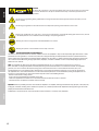 4
4
-
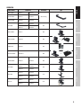 5
5
-
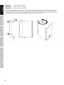 6
6
-
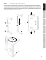 7
7
-
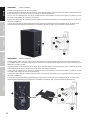 8
8
-
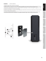 9
9
-
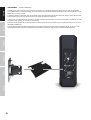 10
10
-
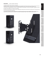 11
11
-
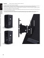 12
12
-
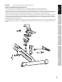 13
13
-
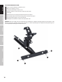 14
14
-
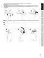 15
15
-
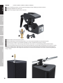 16
16
-
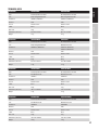 17
17
-
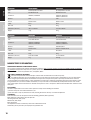 18
18
-
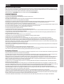 19
19
-
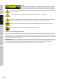 20
20
-
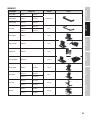 21
21
-
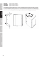 22
22
-
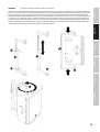 23
23
-
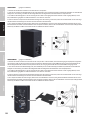 24
24
-
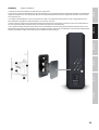 25
25
-
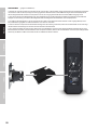 26
26
-
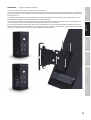 27
27
-
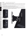 28
28
-
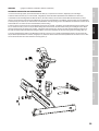 29
29
-
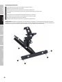 30
30
-
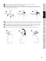 31
31
-
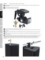 32
32
-
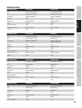 33
33
-
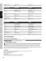 34
34
-
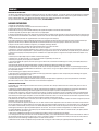 35
35
-
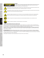 36
36
-
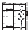 37
37
-
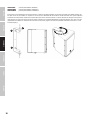 38
38
-
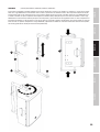 39
39
-
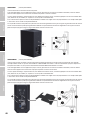 40
40
-
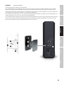 41
41
-
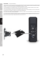 42
42
-
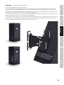 43
43
-
 44
44
-
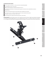 45
45
-
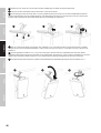 46
46
-
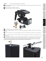 47
47
-
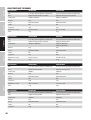 48
48
-
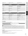 49
49
-
 50
50
-
 51
51
-
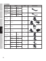 52
52
-
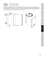 53
53
-
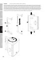 54
54
-
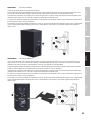 55
55
-
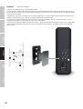 56
56
-
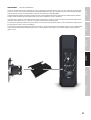 57
57
-
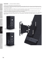 58
58
-
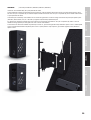 59
59
-
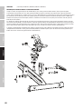 60
60
-
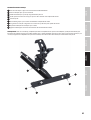 61
61
-
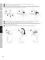 62
62
-
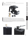 63
63
-
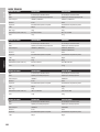 64
64
-
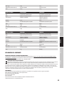 65
65
-
 66
66
-
 67
67
-
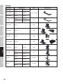 68
68
-
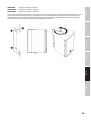 69
69
-
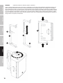 70
70
-
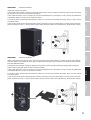 71
71
-
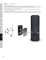 72
72
-
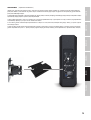 73
73
-
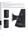 74
74
-
 75
75
-
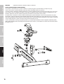 76
76
-
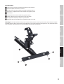 77
77
-
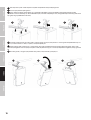 78
78
-
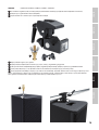 79
79
-
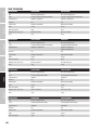 80
80
-
 81
81
-
 82
82
-
 83
83
-
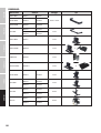 84
84
-
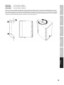 85
85
-
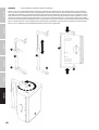 86
86
-
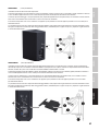 87
87
-
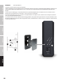 88
88
-
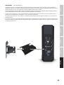 89
89
-
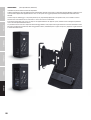 90
90
-
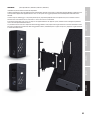 91
91
-
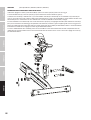 92
92
-
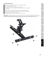 93
93
-
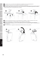 94
94
-
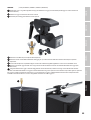 95
95
-
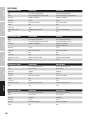 96
96
-
 97
97
-
 98
98
-
 99
99
-
 100
100


LD Systems Stinger 12A G3 12″ Powered Speaker Manual de usuario
- Tipo
- Manual de usuario
en otros idiomas
- français: LD Systems Stinger 12A G3 12″ Powered Speaker Manuel utilisateur
- italiano: LD Systems Stinger 12A G3 12″ Powered Speaker Manuale utente
- English: LD Systems Stinger 12A G3 12″ Powered Speaker User manual
- Deutsch: LD Systems Stinger 12A G3 12″ Powered Speaker Benutzerhandbuch
- polski: LD Systems Stinger 12A G3 12″ Powered Speaker Instrukcja obsługi
Artículos relacionados
-
LD Systems Stinger 12A G3 12″ Powered Speaker Manual de usuario
-
LD Systems MAUI® i1 W El manual del propietario
-
-
LD Systems STINGER SUB 18 G3 Manual de usuario
-
LD Systems SAT 102 W G2 Manual de usuario
-
LD Systems LDEB82G3 Manual de usuario
-
LD Systems STINGER 8 A G3 Manual de usuario
-
-
-
Otros documentos
-
LucyBalu Straight Wandliege Manual de usuario
-
Adam Hall STCLMPB/S Manual de usuario
-
Alpulon ZMWV211 Manual de usuario
-
LUCY BALU Scratching Instrucciones de operación
-
FORCLOVER CJW-PG6473 Manual de usuario
-
LucyBalu Cat Hammock SWING Manual de usuario
-
Adam Mounting plate Manual de usuario
-
 Neomounts W100 Manual de usuario
-
Volkswagen 2H0 071 691 041 Fitting Instruction
