
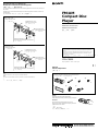
FM/AM
Compact Disc
Player
Sony Corporation 1999 Printed in Japan
Installation/Connections
Instalación/Conexiones
ƒw‚¸¡ ‰u‚ ⁄§‡s–
CDX-C9500
Parts list
Lista de componentes
„s¥ ⁄@˜ “
*I-3-866-782-21*(2)
TO
P
Caution
Cautionary notice for handling the bracket 1.
Handle the bracket carefully to avoid injuring your fingers.
Precaución
Advertencia sobre la manipulación del soporte 1.
Tenga mucho cuidado al manipular el soporte para evitar
posibles lesiones en los dedos.
˜§i
“‘•N⁄p⁄ ‡B‚mƒ«‹[ 1¡C
›n⁄p⁄ ‡B‚mƒ«‹[¡A¥H§K‡˛¶¸⁄ « ¡C
1
× 2
2
5
34
× 4
6 7
For details of the installation of the microphone and rotary commander, refer
to the “Installation for Microphone and Rotary Commander“ supplied with
the unit.
Para obtener información detallada sobre la instalación del micrófono y del
mando rotativo, consulte “Instalación del micrófono y del mando rotativo“
suministrado con la unidad.
ƒ‡ˆ ‡`§J›•'M– ´ ––¤ „“”ƒw‚¸‚ † ¡A‰— • „“ –a»¡'œfi “”¡§‡`§J›•'M– ´ ––
¤ „“”ƒw‚¸¡¤¡C
The numbers in the list are keyed to those in the instructions.
Los números de la lista corresponden a los de las instrucciones.
„ˇ¥ …˘ƒr»P»¡'œfi ⁄⁄“”…˘ƒr‹O⁄@›P“”¡C
4 max. size M5 × 8 mm
Tamaño máx.: M5 × 8mm
‡ ⁄j⁄ ⁄o M5¡ 8 mm
Mounting the unit in a Japanese car
Montaje de la unidad en un automóvil japonés
–N¥» ƒw‚¸' ⁄Ø¥»†£¤T¤fi‚
You may not be able to install this unit in some makes of Japanese cars. In such a case, consult your
Sony dealer.
Es posible que no pueda esta unidad en algunos automóviles japoneses. En tal caso, consulte a su
proveedor Sony.
ƒ‡“”⁄Ø¥»†£¤T¤fi⁄£fl ƒw‚¸¥» ¡Aƒ„fi ¡A‰—‹¢‚ • ƒa“” Sony ‚g P ¡C
TOYOTA
NISSAN
to dashboard/centre console
al salpicadero/consola central
ƒ » ¿ “O¢A⁄⁄¥¡––¤ ‰c
Bracket
Soporte
ƒ«‹[
Existing parts supplied to your car
Piezas existentes suministradas con su automóvil
“ –a' ¤T¤fi“”‡¡¥
Bracket
Soporte
ƒ«‹[
to dashboard/centre console
al salpicadero/consola central
ƒ » ¿ “O¡ ⁄⁄¥¡––¤ ‰c
Bracket
Soporte
ƒ«‹[
Bracket
Soporte
ƒ«‹[
4 max.size M5 × 8 mm
Tamaño máx.: M5 × 8mm
‡⁄j⁄⁄oM5 ¡ 8 mm
Note
To prevent malfunction, install only with the supplied screws 4.
Nota
Para evitar un funcionamiento incorrecto, utilice sólo los tornillos suministrados 4 .
ø
‹ ¤ ⁄ o¥˝‹G» ¡Aƒw‚¸fi ¥ufl ¤ˇ¥˛“ –a“”`‡ • 4¡C
Existing parts supplied to your car
Piezas existentes suministradas con su automóvil
“ –a' ¤T¤fi“”‡¡¥
4 max. size M5 × 8 mm
Tamaño máx.: M5 × 8mm
‡ ⁄j⁄ ⁄o M5¡ 8 mm
4 max. size M5 × 8 mm
Tamaño máx.: M5 × 8mm
‡ ⁄j⁄ ⁄o M5¡ 8 mm

TOP
Installation Instalación ƒw‚¸
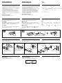
Precautions
•Do not tamper with the four holes on the upper surface of the unit.
They are used for tuner adjustments to be made only by service
technicians.
•Choose the installation location carefully so that the unit will not
interfere with the driver while driving.
•Avoid installing the unit where it would be subject to high
temperatures, such as from direct sunlight or hot air from the
heater, or where it would be subject to dust, dirt or excessive
vibration.
•Use only the supplied mounting hardware for a safe and secure
installation.
Mounting angle adjustment
Adjust the mounting angle to less than 60°.
How to detach and attach the front panel
Before installing the unit, detach the front panel.
To detach A
Before detaching the front panel, be sure to press (OFF) first. Then
press (OPEN) to open the front panel, then slide the front panel to
the right side, and pull out the left side of the front panel.
To attach B
Place the hole in the front panel onto the spindle on the unit as
illustrated, then push the left side in.
Precauciones
•No toque los cuatro orificios de la superficie superior de la unidad.
Estos orificios son para ajustes del sintonizador que solamente
deberán realizar técnicos de reparación.
•Elija cuidadosamente el lugar de montaje de forma que la unidad
no interfiera las funciones normales de conducción.
•Evite instalar la unidad donde pueda quedar sometida a altas
temperaturas, como a la luz solar directa o al aire caliente de
calefacciones, o a polvo, suciedad o vibraciones excesivas.
•Para realizar una instalación segura y firme, utilice solamente la
ferretería de montaje suministrada.
Ajuste del ángulo de montaje
Ajuste el ángulo de montaje a menos de 60°.
Forma de extraer e instalar el panel frontal
Antes de instalar la unidad, extraiga el panel frontal.
A Para extraerlo
Antes de extraer el panel frontal, ceriórese de presionar (OFF).
Después presione (OPEN) a fin de abrirlo, deslícelo hacia la derecha
y, por último, tire de su parte izquierda.
B Para instalarlo
Coloque el orificio del panel frontal en el eje de la unidad,
como se muestra en la ilustración, y después presione la parte
izquierda.
¤ˇ¥˛«e¶•“‘•N
•¥» ‡»‡¡“”4› ⁄p⁄ ‰—⁄¯ ƒ ¥[¥H´«§ ¡A¥ƒ› ¶¨¤ ”ß› § ‡N⁄H›ß‰
‰ ¿ „⁄§¥˛¡C
•¥†¶•¥˛⁄ ¿ 'w A• “”ƒw‚¸ƒ ‚m¥H«K¤ˇ „⁄£§«ˆ“ r p›ß“”rp˚
•` §K–N¥» 'æƒb “•¯‡B¡Aƒp¶§¥œ“‰– • fig¡B•xfi «e¡B'˛ƒh„—¡B»Œ¯…
¥H⁄˛ _ ˚¿EflP“”ƒa⁄Ł¡C
•‹ ⁄Fƒw¥ ⁄˛‰T„Œ“”ƒw‚¸ _¤£¡A››¤ˇ¥˛“ –a“”‡¡¥ ¡C
ƒw‚¸¤⁄« ⁄§‰ ª
‰—ƒb 60 « ¥H⁄”‰ ªƒw‚¸¤⁄« ¡C
ƒpƒ ' ¤ł'M‚¸ t«e›–“O
ƒw‚¸¥» ⁄§«e¡A‰—¥ ' ¤ł«e›–“O¡C
A '¤ł
' ¤ł«e›–“O⁄§«e¡A¶•¥ « ⁄U (OFF) ` ¡C M«Æ¡A« ⁄U (OPEN) `¥H
«K¶}– «e›–“O¡A–N«e›–“O y•LƒV¥kˆ •˘ ˚¡A M«Æ–q«e›–“O“”¥“ …'
B ‚¸ t
ƒp„ˇ' ¥ ¡A–N«e›–“O“” ⁄ •fƒb¥» “”¥D¶b ⁄W¡A M«Æ– ⁄J¥“
…¡C
1
2
m
A
B
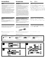
Mounting example
Installation in the dashboard
Ejemplo de montaje
Instalación en el salpicadero
ƒw‚¸¥ ¤
ƒw‚¸ƒb» ¿ “O‚
1
To support the unit
Sujeción de la unidad
⁄«ø „
2
3
1
With the TOP marking up.
Con la marca TOP hacia arriba.
›n¤ˇ–a TOP …— O›–·´⁄W¡C
Bend these claws for a
tight fit, if necessary.
Si es necesario, doble estas uñas
para que encaje firmemente.
›Yƒ‡¥†›n¡A«h¥i¯sƒ–‡o¤˙ˆ·” ¥d⁄ ¡C
4
6
6
6
4
4
5
Dashboard
Salpicadero
»¿“O
Fire wall
Panel cortafuegos
¤⁄ı
2
3
1
Reset button
When the installation and connections are over, be sure to press the
reset button with a ballpoint pen, etc.
Botón de reposición
Cuando finalice la instalación y las conexiones, cerciórese de
presionar el botón de reposición con un bolígrafo, etc.
·_ƒ `
• ƒw‚¸'M‡s– §„ƒ¤«Æ¡A ¨‰—¥˛¶Œfl] § ¥« £·_ƒ ` ¡C

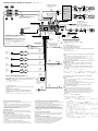
Connections
Conexiones ‰u‚ ⁄§‡s–
Caution
•This unit is designed for negative earth 12 V DC operation only.
•Before making connections, disconnect the earth terminal of the car
battery to avoid short circuits.
•Connect the yellow and red power input leads only after all other
leads have been connected.
•Be sure to connect the red power input lead to the positive 12 V
power terminal which is energized when the ignition key is in the
accessory position.
•Run all earth wires to a common earth point.
•Connect the yellow cord to a free car circuit rated higher than the
unit’s fuse rating. If you connect this unit in series with other stereo
components, the car circuit they are connected to must be rated
higher than the sum of the individual component’s fuse rating. If
there are no car circuits rated as high as the unit’s fuse rating,
connect the unit directly to the battery. If no car circuits are
available for connecting this unit, connect the unit to a car circuit
rated higher than the unit’s fuse rating in such a way that if the unit
blows its fuse, no other circuits will be cut off.
Precauciones
•Esta unidad ha sido diseñada para alimentarse con 12 V CC,
negativo a masa, solamente.
•Antes de realizar las conexiones, desconecte el terminal de puesta a
masa de la batería del automóvil a fin de evitar cortocircuitos.
•Conecte los cables conectores de alimentación amarillo y rojo
solamente después de haber conectado los demás.
•Cerciórese de conectar el cable conector de alimentación rojo a un
terminal de 12 V positivo que se active al poner la llave de
encendido en la posición para accesorios.
•Conecte todos los conductores de puesta a masa a un punto
común.
•Conecte el cable amarillo a un circuito libre del automóvil que
tenga una capacidad superior a la del fusible de la unidad. Si
conecta esta unidad en serie con otros componentes estereofónicos,
el circuito del automóvil al que se encuentran conectados debe
tener una capacidad superior a la suma de las capacidades de los
fusibles de cada componente. Si ningún cicuito del automóvil tiene
una capacidad tan alta como la del fusible de la unidad, conecte
ésta directamente a la batería. Si el automóvil no dispone de ningún
circuito para conectar esta unidad, conéctela a un circuito del
automóvil con capacidad superior a la del fusible de la unidad, de
forma que si se funde el fusible de ésta, no se interrumpa ningún
otro circuito.
“‘•N
• ¥» ¥ufl ¤ˇ¥˛›t•¥– ƒa 12 V “‰‹y„q•‰¡C
• ‡s– «e¡A¥ ' ¥h¤T¤fi„qƒ “”– ƒa” ⁄l¡A¥H§K o¥˝ u‚ ¡C
• ¶ ƒ 'M‹ıƒ „q•‰¿Ø⁄J ‰u¥†¶•ƒb' ƒ‡¤ ¥ƒ ‰u‡£‡s– §„†ƒ¥H«Æ⁄~‡s– ¡
• ‹ıƒ „q•‰ ‰u ¨‰—‡s– ƒ + 12 V „q•‰” ⁄l¡A‚ „q•‰” ⁄lƒb¤T¤fi o ˚
´I⁄ı˘_ ˝‡B' »†§Uƒ ‚mfi ⁄~‡q„q¡C
• –N' ƒ‡ƒa‰u‡£‡s– ¤ ƒP⁄@ƒa´I¡C
•–N¶ ƒ ‰u‡s– ¤ ⁄j' ¥» «O I •ˆB'wfie¶q“”¥…ƒß¥˛“”¤T¤fi„q‚
›Y–N¥» 'M¤ ¥ƒ¥ ¯Ø`n‚¸‚m‹ ⁄‹ƒŒ`p¡A' ‡s– “”¤T¤fi„q‚ fie¶q¥†
' ƒU† ƒ¤ «O I •fie¶q“”`‘'M¡C
›Y¤Sƒ‡»P¥» «O I •ˆB'wfie¶q⁄@…¸⁄j“”¤T¤fi„q‚ ¥i‚Œ§Q¥˛¡A¥i–N
“‰– ‡s– ¤ „qƒ ⁄W¡C›Y L A• “”¤T¤fi„q‚ ¥i¥˛' ‡s– ¥» ¡A‰—–N
‡s– ¤ ⁄j' ¥» «O I •fie¶q“”¤T¤fi„q‚ ⁄W¡C‡o…¸¡A›Y¥» “”«O I
´_⁄F¡A⁄]⁄£›P' ⁄`´_¤ ¥ƒ„q‚ ¡C
SUB OUT
(MONO)
BUS CONTROL IN
BUS AUDIO IN
BUS
AUDIO IN
BUS
CONTROL IN
LINE OUT
FRONT
LINE OUT
REAR
Source selector
Selector de fuente
› •‰«H‚„¿ „
Equipment used in illustrations (not supplied)
Note
For connecting two or more changers, the source selector XA-C30
(optional) is necessary.
Equipo utilizado en las ilustraciones (no suministrado)
Nota
Cuando desee conectar dos o más cambiadores, necesitará un selector
de fuente XA-C30 (opcional).
„ˇ⁄⁄¤ˇ¥˛“”‡]‡˘¡] L“ –a¡^
ø
›Y›n‡s– 2 »O'˛ 2 »O¥H⁄W·«”— fi ¡A«K¶•¤ˇ¥˛«H‚„•‰¿ „ XA-C30
¡]¿ `˚¥ ¡^¡C
Power amplifier
Amplificador de potencia
¥\†v'æ⁄j „
Front speakers
Altavoces delanteros
«e·›`n „
Rear speakers
Altavoces traseros
«Æ·›`n „
CD/MD changer
Cambiador de CD/MD
CD/MD ·«”—
Active subwoofer
Altavoz activo de potenciación de graves
ƒ‡•‰ ˘§C› ·›`n „
Diagramas de conexión
Connection diagram
‰u‚ ‡s– „ˇ
BUS CONTROL IN
BUS AUDIO IN
Frequency select switch
The AM (FM) tuning interval is factory-set to the 9K (50 K) position.
If the frequency allocation system of your country is based on
10 kHz (200 kHz) interval, set the switch on the bottom of the unit to
the 10 K (200 K) position before making connections.
Note
When you change the position of the switch, be sure to press the reset
buttons after the connections are completed.
W†v¿ ¶}ˆ
AM (FM) ‰ ¿ ¶¡„jƒb¥X…t«e‡Q‡]'wƒb 9 K (50 K) ƒ ‚m⁄W¡C›Y¶Q Œ“”
W†v⁄ t¤t†˛‹O¥H 10 KHz (200 KHz) ¶¡„j‹ ´ƒ“”¡A‡s– «e¡A‰—–N¥»
'‡‡¡⁄W“”¶}ˆ ‡]'wƒb 10 K (200 K) ƒ ‚m⁄W¡C
ø
§ ¯ ¶}ˆ ƒ ‚mfi ¡A‰—⁄@'wƒb‡s– ƒn „«Æ« ⁄U·_ƒ `
¡C
Selector de frecuencia
El intervalo de sintonía de AM (FM) ha sido ajustado en fábrica en la
posición 9 K (50 K). Si el sistema de asignación de frecuencias de su
país se basa en el intervalo de 10 kHz (200 kHz), ponga este selector,
situado en la base de la unidad, en la posición 10 K (200 K) antes de
realizar las conexiones.
Nota
Cuando haya cambiado la posición del selector, cerciórese de presionar los
botones de reposición después de haber finalizado las conexiones.
I
II
III
Warning when installing in a car without ACC
(accessory) position on the ignition key
switch
Be sure to press (OFF) on the unit for two seconds to turn off
the clock display after turned off the engine.
When you press (OFF) momentarily, the clock display does not turn
off and this causes battery wear.
• ƒb´I⁄ı˘_ ˝¶}ˆ ¤S¤ª»†§Uƒ ‚m“”¤T¤fi¤‰«
fi “”˜ §i
‰—‰T»{ƒbˆ ‡‹ o ˚ «Æ« £ (OFF) ` ¤ ‹ ˜`¥Hˆ ‡‹fi ˜`¯ª¥ ¡C
• –z u…¨« £ (OFF) ` ¡Afi ˜`¯ª¥ –N⁄£fl ˆ ‡‹¤ˆ¥B–N⁄ _„qƒ fiłfl ¡C
Advertencia sobre la instalación en un
automóvil que no disponga de posición ACC
(accesorios) en el interruptor de la llave de
encendido
Asegúrese de presionar (OFF) en la unidad durante dos
segundos para desactivar la indicación del reloj una vez apagado
el motor.
Si presiona (OFF) momentáneamente, la indicación del reloj no se
desactivará y esto causará el desgaste de la batería.

Notas sobre los cables de control y de fuente de alimentación
• El cable de control de la antena motorizada (azul) suministrará +12 V CC
cuando conecte la alimentación de la unidad.
• Si se ha instalado una antena de recepción de FM/AM en el cristal
trasero/lateral del automóvil, es necesario conectar el cable de control de
la antena motorizada (azul) o el cable auxiliar de entrada de
alimentación (rojo) al terminal de potencia del amplificador de antena
existente. Para obtener información detallada, consulte a su proveedor.
• Con esta unidad no podrá emplearse una antena motorizada desprovista
de caja de relé.
Conexión para protección de la memoria
Si conecta el cable de entrada amarillo, el circuito de la memoria recibirá
siempre alimentación, incluso aunque ponga la llave de encendido en la
posición OFF.
Notas sobre la conexión de los altavoces
• Antes de conectar los altavoces, desconecte la alimentación de la unidad.
• Utilice altavoces con una impedancia de 4 a 8 Ohmios, y con la potencia
máxima admisible adecuada, ya que de lo contrario podría dañarlos.
• No conecte los terminales del sistema de altavoces al chasis del
automóvil, ni los del altavoz izquierdo a los del derecho.
• No intente conectar los altavoces en paralelo.
Notes on the control and power supply leads
• The power aerial control lead (blue) supplies +12 V DC when you turn on
the unit.
• When your car has a built-in FM/AM aerial in the rear/side glass, it is
necessary to connect the power aerial control lead (blue) or the accessory
power input lead (red) to the power terminal of the existing aerial
booster. For details, consult your dealer.
• A power aerial without relay box cannot be used with this unit.
Memory hold connection
When the yellow power input lead is connected, power will always be
supplied to the memory circuit even when the ignition key is turned off.
Notes on speaker connection
• Before connecting the speakers, turn the unit off.
• Use speakers with an impedance of 4 to 8 ohms, and with adequate
power handling capacities. Otherwise, the speakers may be damaged.
• Do not connect the terminals of the speaker system to the car chassis,
and do not connect the terminals of the right speaker with those of the
left speaker.
• Do not attempt to connect the speakers in parallel.
• Do not connect any active speakers (with built-in amplifiers) to the
speaker terminals of the unit. Doing so may damage the active speakers.
to a car’s illumination signal
Be sure to connect the black earth to it first.
a una señal de iluminación del automóvil
Asegúrese de conectar primero a este terminal el conductor de puesta a masa negro.
ƒ ¤T¤fi“”• 'œ«H‚„
¨‰—›”¥ –N¶´ƒ ƒa‰u»P¤ ‡s– ¡C
to the interface cable of a car telephone
al cable de interfaz de un teléfono para automóvil
ƒ ¤T¤fi„q‚ “”– ⁄f„q˘l
to the +12 V power terminal which is energized at all times
Be sure to connect the black earth lead to it first.
a un terminal de alimentación de +12 V que esté permanentemente activado
Asegúrese de conectar primero a este terminal el conductor de puesta a
masa negro.
ƒ ‚g–‘‡£‡q„q“” +12 V „q•‰” ⁄l
¨‰—›”¥ –N¶´ƒ – ƒa ‰u»P¤ ‡s– ¡C
to a metal point of the car
First connect the black earth lead, then connect the yellow and red power
input reads.
a un punto metálico del automóvil
En primer lugar, conecte el conductor de puesta a masa negro y, a
continuación, los cables de entrada de alimentación amarillo y rojo.
ƒ ¤T¤fi“”“ ˜ ‡¡ƒ
›”¥ ‡s– ¶´ƒ – ƒa ‰u¡A M«ÆƒA‡s– ¶ ƒ 'M‹ıƒ „q•‰¿Ø⁄J ‰u¡C
to the +12 V power terminal which is energized in the accessory position of
the ignition key switch
Notes
• If there is no accessory position, connect to the +12 V power (battery) terminal
which is energized at all times.
Be sure to connect the black earth lead to it first.
• When your car has a built-in FM/AM aerial in the rear/side glass, see “Notes on
the control and power supply leads.”
a un terminal de alimentación de +12 V que se active en la posición para
accesorios de la llave de encendido
Notas
• Si no existe posición para accesorios, realice la conexión al terminal de
alimentación (batería) de +12 V que reciba energía permanentemente.
Asegúrese de conectar primero a este terminal el conductor de puesta a masa
negro.
• Si el automóvil incorpora una antena de recepción de FM/AM en el cristal
trasero/lateral, consulte “Notas sobre los cables de control y de fuente de
alimentación”.
ƒ ƒb´I⁄ı˘_ ˝“”»†§Uƒ ‚m⁄W‡q„q“” +12 V „q•‰” ⁄l
ø
•
›Y¤Sƒ‡»†§Uƒ ‚m¡A«h‰—‡s– ƒ –‘fi ‡q„q“” +12 V „q•‰¡]„qƒ ¡^” ⁄l¡C
¨‰—›”¥ –N¶´ƒ – ƒa ‰u»P¤ ‡s– ¡C
•
–z“”¤T¤fi“”«Æ¡ …‹`… ¡⁄⁄ƒp“G⁄”‚¸ƒ‡ FM/AM ⁄ ‰u¡A§Y‰— ‹ ¡§––¤ 'M„q•‰‰u¶•“ ¡¤¡C
to the power aerial control lead or power supply lead of aerial booster amplifier
Notes
• It is not necessary to connect this lead if there is no power aerial or aerial
booster, or with a manually-operated telescopic aerial.
• When your car has a built-in FM/AM aerial in the rear/side glass, see “Notes on
the control and power supply leads.”
al cable de control de la antena motorizada, o al cable de fuente de alimentación
del amplificador de antena
Notas
• Si no se dispone de antena motorizada ni de amplificador de antena, o se
utiliza una antena telescópica accionada manualmente, no es necesario
conectar este cable.
• Si el automóvil incorpora una antena de recepción de FM/AM en el cristal
trasero/lateral, consulte “Notas sobre los cables de control y de fuente de
alimentación”.
ƒ „q ˚⁄ ‰u––¤ ‰u'˛⁄ ‰u⁄ £'æ⁄j „“”„q•‰ ‰u
ø
•
ƒp L„q ˚⁄ ‰u¡A…W £ „¡A'˛¥˛⁄ §@“”fiM” ƒ¡⁄ ‰u¡A«K⁄£¶•‡s– ƒ„ ‰u¡C
•
–z“”¤T¤fi“”«Æ¡ …‹`… ¡⁄⁄ƒp“G⁄”‚¸ƒ‡ FM/AM ⁄ ‰u¡A§Y‰— ‹ ¡§––¤ 'M„q•‰‰u¶•“ ¡¤¡C
––¤ 'M„q•‰‰u¶•“
•
– ‡q¥» fi ¡A„q ˚⁄ ‰u––¤ ‰u¡]´¯ƒ ¡^«Kfl ·£¤ +12 V “‰‹y„q¡C
•
–z“”¤T¤fi“”«Æ¡ …‹`… ¡⁄⁄ƒp“G⁄”‚¸ƒ‡ FM/AM ⁄ ‰u¡A§Y‰—§ „q ˚⁄ ‰u––¤ ‰u
¡]´¯ƒ ¡^'˛“ –a“”„q•‰‰u¡]‹ıƒ ¡^‡s– ¤ †{ƒ‡“”⁄ ‰u…W £ „“”„q•‰” ⁄l⁄W¡C
⁄”fie¡A‰—‹¢‚ ¥ ' '–¡C
•
¥» ⁄£fl ¤ˇ¥˛⁄£¤ª‡˘˜~„q‰c“”„q ˚⁄ ‰u¡C
«O«ø O —¥\fl “”‡s– “k
• ‡s– ƒn¶ ƒ „q•‰¿Ø⁄J ‰ufi ¡A§Y¤ˇ¤T¤fi o ˚ ´I⁄ı˘_ ˝‡Q´ ƒb¶}„qƒ ‚m¡
•‰⁄·˜~˜ –N„q‹y¤ „ O —¥\fl ¥˛„q‚ ¡A¥H«O«ø' O —…˘ ¡C
‡s– ·›`n „¶•“
•
‡s– ·›`n „„q‰u⁄§«e¡A‰—¥ ˆ –…¥» „q•‰¡C
•
‰—¤ˇ¥˛ 4 ƒ 8 £[ “ § ¤ˆ¥B¤ªƒ‡¤‹ ¥\†v“”·›`n „¡C§_«h•|•lˆa·›`n „¡C
•
⁄£¥i–N·›`n „“”” ⁄l‡s– ƒ ¤T¤fi'‡‰L¡A⁄]⁄£¥i–N¥“·›`n „'M¥k·›`n „‹ ‡s
•
⁄£¥i¤ˆ`p·›`n „¡C
•
⁄£¥i‡s– ƒ‡•‰·›`n „¡]⁄”‚¸ƒ‡'æ⁄j „“ ¡^ƒ ¥» “”·›`n „” ⁄l¡C§_«h•|•lˆaƒ
·›`n „¡C‰—“‘•N‡o¤˙” ⁄l¥ufl ‡s– L•‰·›`n „¡C
FRONT LINE OUT
REAR
LINE OUT
SUB OUT (MONO)
from car antenna
de la antena del automóvil
¤ ƒ ¤T¤fi⁄ ‰u
BUS CONTROL IN
REMOTE IN
Fuse (10 A)
Fusible (10 A)
«OI• (10A)
7
BUS AUDIO IN
AMP REM
Blue/white striped
Con raya azul/blanca
´¯ƒ¡¥ƒ–łfl
Max. supply current 0.3 A
Corriente máx. de alimentación de 0,3 A
‡ ⁄j¤ „q‹y 0.3 A
Max. supply current 0.1 A
Corriente máx. de alimentación de 0,1 A
‡ ⁄j¤ „q‹y 0.1 A
ANT REM
Blue
Azul
´¯ƒ
Sky blue
Azul celeste
⁄ ´¯ƒ
ATT
Red
Rojo
‹ıƒ
Yellow
Amarillo
¶ƒ
Black
Negro
¶´ƒ
ILLUMINATION
Orange/white striped
Con raya naranja/blanca
ƒ¡¥ƒ–łfl
Purple
Púrpura
ƒ
Green
Verde
”æƒ
Grey
Gris
ƒ˙ƒ
White
Blanco
¥ƒ
Right
Derecho
¥k
Left
Izquierdo
¥“
Right
Derecho
¥k
Left
Izquierdo
¥“
To AMP RENOTE IN of an optional power amplifier.
This connection is only for ampilifiers. Connecting any
other system may damage the unit
Para conectar a AMP REMOTE IN del amplificador de
potencia opcional.
Esta conexión es sólo para amplificadores. La conexión
de cualquier otro sistema puede dañar la unidad.
ƒ ¿ `˚“”¥\†v'æ⁄j „“” AMP REMOTE IN¡]'æ⁄j „»»––
¿Ø⁄J¡^¡C
¥»‡s– ¶¨¥˛' 'æ⁄j „¡C‡s–¥ƒ¤¥ƒ¤t†˛¥ifl •|•l˜[¥» ¡C
Connection example / Ejemplo de conexiones¡ ‰u‚ ‡s– „ˇ¤
Choke coil box
Caja de la bobina de
impedancia protectora
§ª‹y ؉c
Source selector
XA-C30
Selector de fuente
XA-C30
› •‰¿ „
XA-C30
Supplied with the CD/MD changer
Suministrado con el cambiador de CD/MD
“ –a' CD/MD ·«”—
Supplied with the XA-C30
Suministrado con el XA-C30
“ –a' XA-C30
Microphone
Micrófono
‡`§J›•
RCA pin cord (not supplied)
Cable con clavijas RCA (no suministrado)
RCA ” ‚}„q‰u¡] L“ –a¡^
Rotary commander
Mando rotativo
– ´ ––¤ „
RCA pin cord (not supplied)
Cable con clavijas RCA (no suministrado)
RCA ” ‚}„q‰u¡] L“ –a¡^
Filter
Filtro
´o“i „
MIC IN
-
 1
1
-
 2
2
-
 3
3
-
 4
4


en otros idiomas
- English: Sony CDX-C9500 Installation guide
Artículos relacionados
-
Sony XR-C2600 Guía de instalación
-
-
-
-
-
-
-
-
-