Hampton Bay CF548KR-160 BN Guía de instalación
- Categoría
- Ventiladores domésticos
- Tipo
- Guía de instalación

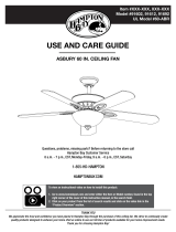
USE AND CARE GUIDE
Questions, problems, missing parts? Before returning to the store
call
Hampton Bay Customer Service
8 a.m. - 6 p.m., EST, Monday-Friday
1-855-HD-HAMPTON
HAMPTONBAY.COM
COBRAM 48 INCH CEILING FAN
Item #609-619
Model #CF548KR-CL160 (BN)
THANK YOU
Item# 161-646

2
Table of Contents
14
14
16
14
Operation
Care and Cleaning 15
Troubleshooting 16
Service Parts 17
Remote Control Operating Instructions
Reverse Function Button Operating Instructions
Installing the Remote Control Holder
.....................................................................
...........................
..............
.............................
.......................................................
..........................................................
................................................................
Installation
Table of Contents 2
Safety Information 2
Warranty 3
Pre-Installation
Specifications
Tools Required
Hardware Included
Package Contents
3
3
3
4
5
6
Assembly
Hanging the Fan
Attaching the Fan Blade Assemblies
Installing the Light Kit
7
7
12
13
........................................................
.......................................................
.......................................................................
.............................................................
.............................................................
............................................................
......................................................
........................................................
....................................................................
......................................................................
..........................................................
..............................
.................................................
Safety Information
□ READ AND SAVE THESE INSTRUCTIONS.
□ To reduce the risk of electric shock, ensure electricity has
been turned off at the circuit breaker or fuse box before
beginning.
□ All wiring must be in accordance with the National Electrical
Code “ANSI/NFPA 70-1999” and local electrical codes.
Electrical installation should be performed by a qualified
licensed electrician.
□ The outlet box and support structure must be securely
mounted and capable of reliably supporting a minimum of 35
lbs. Use only UL Listed outlet boxes marked “FOR FAN
SUPPORT.”
□ The fan must be mounted with a minimum of 7 ft. clearance
from the trailing edge of the blades to the floor.
□ To avoid personal injury or damage to the fan and other
items, be cautious when working around or cleaning the fan.
□ Do not use water or detergents when cleaning the fan or fan
blades. A dry dust cloth or lightly dampened cloth will be
suitable for most cleaning.
□ After making electrical connections, spliced conductors
should be turned upward and pushed carefully up into the
outlet box. The wires should be spread apart with the
grounded conductor and the equipment-grounding conductor
on one side of the outlet box and ungrounded conductor on
the other side of the outlet box.
□ All setscrews must be checked and retightened where
necessary before installation.
WARNING: To reduce the risk of personal injury, do not
bend the blade arms (also referred to as flanges), when
installing the brackets, balancing the blades, or cleaning the
fan.
WARNING: Do not insert foreign objects between rotating
fan blades.
WARNING: To reduce the risk of fire, electric shock, or
personal injury, mount the fan to the outlet box marked
acceptable for fan support with the screws provided with the
outlet box.
CAUTION: To reduce the risk of personal injury, use only
the screws provided with the outlet box.
NOTE: Suitable for use with solid-state speed controls.

MOC.YABNOTPMAH3
Please contact 1-855-HD-HAMPTON for further assistance.
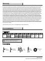
SPECIFICATIONS
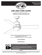
TOOLS REQUIRED
Phillips
screwdriver
Electrical
Tape
Wire
stripper
Flat blade
screwdriver
Step
ladder
Pre-InstallationPre-Installation
48 in.
Low
Medium
High
120
Fan
size Watts RPM CFMSpeed Volts Amps
1.63 ft.
N.
W. G.W. C.F.
0.21
0.28
0.39
13.3
23.3
46.8
85
120
175
1873
2724
4102
6.52 kg
(14.37 lb)
7.60 kg
(16.76 lb)
Warranty
We warrant the fan motor to be free from defects in workmanship and material present at time of shipment from the factory for a period
of lifetime after the date of purchase by the original purchaser. We also warrant that all other fan parts, excluding any glass or acrylic
blades, to be free from defects in workmanship and material at the time of shipment from the factory for a period of one year after the
date of purchase by the original purchaser. We agree to correct such defects without charge or at our option replace with a comparable or
superior model if the product is returned. To obtain warranty service, you must present a copy of the receipt as proof of purchase. All
costs of removing and reinstalling the product are your responsibility. Damage to any part such as by accident, misuse, improper installa-
tion or by affixing any accessories, is not covered by this warranty. Because of varying climatic conditions this warranty does not cover
any changes in brass finish, including rusting, pitting, corroding, tarnishing or peeling. Brass finishes of this type give their longest useful
life when protected from varying weather conditions. A certain amount of “wobble” is normal and should not be considered a defect.
Servicing performed by unauthorized persons shall render the warranty invalid. There is no other express warranty. We hereby disclaim
any and all warranties, including but not limited to those of merchantability and fitness for a particular purpose to the extent permitted by
law. The duration of any implied warranty which cannot be disclaimed is limited to the time period as specified in the express warranty.
Some states do not allow limitation on how long an implied warranty lasts, so the above limitation may not apply to you. The retailer shall
not be liable for incidental, consequential, or special damages arising out of or in connection with product use or performance except as
may otherwise be accorded by law. Some states do not allow the exclusion of incidental or consequential damages, so the above
exclusion or limitation may not apply to you. This warranty gives specific legal rights, and you may also have other rights which vary from
state to state. This warranty supersedes all prior warranties. Shipping costs for any return of product as part of a claim on the warranty
must be paid by the customer.
Contact the Customer Service Team at 1-855-HD-HAMPTON or visit www.hamptonbay.com.
NOTE: These are approximate measures. They do not
include amps and wattage used by the light kit.

4
Pre-Installation (continued)
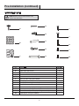
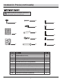
HARDWARE INCLUDED
AA
BB
CC
DD
EE
FF
GG
HH
Part
Description
Quantity
II
JJ
KK
LL
MM
Blade screw
Fiber washer (not to scale)
Balance kit (not to scale)
Remote control holder mounting screws
Wire nuts
16
16
1
2
6
Hitch pin (preassembled)
Lock pin (not to scale) (preassembled)
Hanger ball set screw (preassembled)
Mounting bracket screw (preassembled)
1
1
1
2
Cross pin (not to scale) (preassembled) 1
Fan motor assembly coupling set screw (preassembled) 2
Fan motor assembly mounting ring screw (preassembled) 3
Light kit plate screw (preassembled) 3
NOTE: Hardware shown to actual size unless noted
otherwise in the table below.
AA
BB
CC
DD
FF
EE
GG
HH
II
JJ
KK
LL
MM

Please contact 1-855-HD-HAMPTON for further assistance.
MOC.YABNOTPMAH5
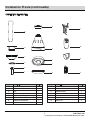
PACKAGE CONTENTS
Pre-Installation (continued)
D
F
G
I
B
A
E
C
J
K
L
M
N
O
D
E
F
Canopy cover
Hanger ball (preassembled)
Downrod (preassembled)
1
1
1
Part
A
B
C
Qu
antity
5
1
1
D
escription
Blade
Mounting bracket
Canopy
H Fan motor assembly 1
G 1Couping cover
L
M
N
1
1
1
Part
I
J
K
Qu
antity
1
1
1
D
escription
O 1
17W LED assembly (preassembled)
Glass shade
Light kit plate (preassembled)
Receiver
Remote control
12V Battery
Remote control holder
H

6
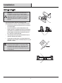
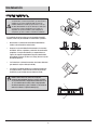
WARNING: To reduce the risk of fire, electric shock, or
personal injury, mount the fan to an outlet box marked
acceptable for fan support using the screws provided with the
outlet box. An outlet box commonly used for the support of
lighting fixtures may not be acceptable for fan support and
may need to be replaced. If in doubt, consult a qualified
electrician.
Installation
MOUNTING OPTIONS
1
1
1
3
2
If your ceiling fan does not have an existing UL-listed
mounting box, then install one using the following instructions:
□ Disconnect the power by removing the fuses or turning off
the circuit breakers.
□
□
Secure the outlet box (1) (not included) directly to the
building structure. Use appropriate fasteners and materials
(not included). The outlet box and its bracing must be able
to fully support the weight of the moving fan (at least 35
lbs.). Do not use a plastic outlet box.
The illustrations to the right show three different ways to
mount the outlet box (not included).
□
To hang your fan where there is an existing fixture but no
ceiling joist, you may need an installation hanger bar (3) (not
included), as shown.
NOTE: You may need a longer downrod to maintain proper
blade clearance when installing on a steep, sloped ceiling.
The maximum angle allowable is 18°. If the canopy touches
the downrod, remove the decorative canopy bottom cover
and turn the canopy 180° before attaching the canopy to the
mounting plate (2).

Please contact 1-855-HD-HAMPTON for further assistance.
MOC.YABNOTPMAH7
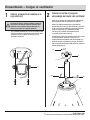
Assembly — Hanging the Fan
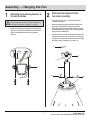
1
Attaching the mounting bracket to
the electrical box
□
Attach the mounting bracket (B) to the outlet box with
two screws and washers provided with the outlet box.
Make sure the mounting bracket (B) is tightened
securely.
To reduce the risk of fire, electric shock, or WARNING:
other personal injury, mount the fan only to an outlet box or
supporting system marked acceptable for fan support
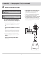
□
Loosen the two set screws (JJ) from the fan motor
assembly (H) coupling.
□
Remove the hitch pin (GG) and lock pin (HH) from the
downrod (F). Remove the hanger ball (E) from the
downrod (F) by loosening the hanger ball set screw (II),
and removing the cross pin (FF), then sliding the hanger
ball (E) off of the downrod (F).
□
Carefully feed the fan wires up through the downrod (F).
Thread the downrod (F) into the fan motor assembly (H)
coupling. Line up the holes and replace the lock pin (HH)
and hitch pin (GG). Tighten the set screws (JJ).
JJ
GG
FF
F
E
II
HH
H
Attaching the downrod to the
fan motor assembly
2
B

8
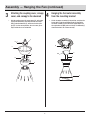
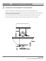
3
Attaching the coupling cover, canopy
cover, and canopy to the downrod
Assembly — Hanging the Fan (continued)
□
Slip the coupling cover (G), canopy cover (D), and canopy
(C) onto the downrod (F). Carefully reinstall the hanger
ball (E) onto the downrod (F), and ensure that the cross
pin (FF) is in the correct position, the set screws (II) are
tight, and the wires are not twisted.
F
NN
F
II
FF
B
G
E
C
D
4
Hanging the fan motor assembly
from the mounting bracket
E
H
□
Lift the fan motor assembly (H) into position, and place the
hanger ball (E) into the mounting bracket (B). Rotate the
fan motor assembly (H) until the check groove drops into
the registration slot (NN) and seats rmly. The downrod (F)
should not rotate if this is done correctly.

Please contact 1-855-HD-HAMPTON for further assistance.
9 HAMPTONBAY.COM
M
L
L
B
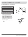
Assembly — Hanging the Fan (continued)
Preparing the receiver and remote control
5
This remote control unit is equipped with 16 code
combinations to prevent possible interference from or to
other remote units. The frequency switches on your
receiver (L) and remote control (M) have been preset at
the factory. Please recheck to make sure the switches on
the remote control (M) and the receiver (L) are set to the
same position. Any combination of settings will operate
the fan as long as the remote control (M) and receiver
(L) are set to the same position.
□
Insert the receiver (L) into the mounting bracket (B)
with the flat side of the receiver (L) facing the
ceiling.
CAUTION: Do not use with a wall light dimmer switch.
WARNING: To avoid possible electrical shock, ensure the
electricity is turned off at the main fuse box before wiring.
NOTE: If you feel you do not have enough electrical
wiring knowledge or experience, have your fan installed
by a licensed electrician.

10
Assembly — Hanging the Fan (continued)
6
Making the electrical connections
1
WARNING: To avoid possible electrical shock, ensure the
electricity is turned off at the circuit breaker or main fuse box
before wiring.
WARNING: Check to see that all connections are tight,
including the ground, and that no bare wire is visible at the
wire nuts, except for the ground wire.
Follow the steps below to connect the fan to your house
supply wires. Secure the wire nuts (EE) supplied with your
fan by wrapping the connections with electrical tape.
ON
BBB
CCC
DDD
EEE
L
EE
FFF
GGG
HHH
III
JJJ
KKK
LLL
Motor to receiver electrical connections:
□ Connect the black wire (CCC) from the fan to the black
wire (GGG) marked "TO MOTOR L" from the receiver
(L).
□ Connect the white wire (AAA) from the fan to the white
wire (EEE) marked "TO MOTOR N" from the receiver
(L).
□ Connect the blue wire (BBB) from the fan to the blue
wire (FFF) marked "For Light" from the receiver (L).
Receiver to house supply wires electrical connections:
□ Connect the black (hot) wire (JJJ) from the ceiling to
the black wire (HHH) marked "AC in L" from the
receiver (L).
□ Connect the white (neutral) wire (KKK) from the
ceiling to the white wire (III) marked "AC in N" from
the receiver (L).
□ If your outlet box (1) has a ground wire (LLL) (green
or bare copper), connect it to the fan ground wires
(DDD); otherwise, connect the hanging ball (E)
ground wire to the mounting bracket (B).
□ Secure the wire connection with a plastic wire nut
(EE) provided with the electrical hardware.
□ After connecting the wires, spread them apart so that
the green and white wires are on one side of the
outlet box (1) and the black and blue wires are on the
other side. Carefully tuck the wire connections up
into the outlet box (1).
AAA

Please contact 1-855-HD-HAMPTON for further assistance.
11
HAMPTONBAY.COM
KK
KK
C
D
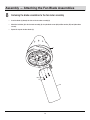
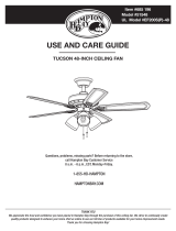
7
Securing the fan motor assembly to the mounting bracket
□
Remove one screw (KK) from the mounting bracket (B) and loosen the other screw (KK) approximately 1/4 turn.
□
Carefully raise the canopy (C) up to the mounting bracket (B), and ensure the loosened screw (KK) is inserted into the key hole on
the canopy (C). Rotate the canopy (C) clockwise.
□
Secure the canopy (C) by replacing the screw (KK) previously removed and tightening the screw (KK) previously loosened.
□
Place the canopy cover (D) on the canopy (C), and rotate the canopy cover (D) clockwise until it locks into position.
Assembly — Hanging the Fan (continued)
B

12
□
Insert the blades (A) through the slots on the fan motor assembly (H).
□
Attach the fan blades (A) to the fan motor assembly (H) using the blade screws (AA) and ber washer (BB) and tighten them
securely.
□
Repeat this step for the other blades (A).
Fastening the blade assemblies to the fan motor assembly
8
Assembly — Attaching the Fan Blade Assemblies
H
A
AA
BB

Please contact 1-855-HD-HAMPTON for further assistance.
13
HAMPTONBAY.COM
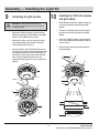
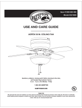
Installating the light kit plate
9
Assembly — Installing the Light Kit
□
Remove the 17W LED assembly (J) from the light kit
plate (I) by removing three light kit plate screws (MM).
Set these screws (MM) aside for use later.
□
Place the key holes from the light kit plate (I) over the
two screws (LL) previously loosened from the fan motor
assembly (H) mounting ring. Turn the light kit plate (I)
until it locks in place at the narrow section of the key
holes. Secure by tightening the two screws (LL)
previously loosened and the one screw (LL) previously
removed.
□
Remove one of three screws (LL) from the fan motor
assembly (H) mounting ring and loosen, but do not
remove, the other two screws (LL).
CAUTION: To reduce the risk of electric shock,
disconnect the electrical supply circuit to the fan before
installing the light kit.
Installing the 17W LED assembly
and glass shade
10
I
K
MM
I
J
I
LL
H
□
While holding the 17W LED assembly (J) under your
fan, rmly snap the wire connection plugs (OO)
together.
□
Position the 17W LED assembly (J) on the light kit
plate (I) and ensure the screw holes are properly
aligned.
□
Secure the 17W LED assembly (J) by replacing the
three screws (MM) previously removed. Tighten all
screws securely.
□
Attach the glass shade (K) to the light kit plate (I)
by twisting tightly.
MM
I
J
H
OO

14
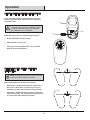
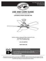
NOTE: To operate the reverse function on this fan, press the
reverse function button while the fan is running.
Warm weather - (Counterclockwise Direction) A downward air
flow creates a cooling effect. This allows you to set your air
conditioner on a higher setting without affecting your comfort.
Cool weather - (Clockwise Direction) An upward air flow moves
warm air off the ceiling. This allows you to set your heating unit
on a lower setting without affecting your comfort.
Operation
M
O
PP
REMOTE CONTROL OPERATING INSTRUCTIONS
REVERSE FUNCTION BUTTON OPERATING
INSTRUCTIONS
Install a 12V battery (O) into the remote control (M). To prevent
damage to the remote control, remove the battery if not used for
long periods of time.
HI, MED, LOW buttons: Sets the fan speed.
FAN OFF button: Turns the fan off.
LIGHT button: Turns the light ON or OFF. Press and hold the
button to set the desired brightness.
□
□
□
Restore power to the ceiling fan and test for proper operation.
□
□
Reverse function button (PP): Controls the fan direction.
WARNING: Do not short-circuit, disassemble, heat up,
connect improperly, or dispose of used batteries in re. Do
not recharge or mix batteries with used or other battery
types. Immediately remove used batteries.

Please contact 1-855-HD-HAMPTON for further assistance.
15
Operation (continued)
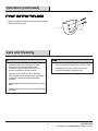
Care and Cleaning
□ Check the support connections, brackets, and blade
attachments twice a year. Ensure they are secure.
Because of the fan’s natural movement, some
connections may become loose over time. It is not
necessary to remove the fan from the ceiling.
□ Clean your fan periodically. Use only a soft brush or
lint-free cloth to avoid scratching the finish. The plating is
sealed with a lacquer to minimize discoloration or
tarnishing.
□ (Optional) Apply a light coat of furniture polish to the wood
blades.
□ (Optional) Cover small scratches with a light application of
shoe polish.
Do
□ Do not use water when cleaning. Water could damage the
motor, or the wood, or possibly cause an electrical shock.
□ Do not apply oil to your fan or motor. The motor has
permanently-lubricated sealed ball bearings.
Do not
N
DD
INSTALLING THE REMOTE CONTROL HOLDER
□
Attach the remote control holder (N) with the two remote control
holder mounting screws (DD).
MOC.YABNOTPMAH

16
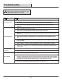
Troubleshooting
WARNING: Ensure the power is off at the electrical
panel box before you attempt any repairs. Refer to the section
“Making the Electrical Connections” on page 10.
□ Do not connect the fan with wall mounted variable speed control(s).
□ Check to make sure the dip switches from the remote control and receiver are set to the same frequency.
□ Check that all blade and blade arm screws are secure.
□ Most fan wobble problems are caused when blade levels are unequal. Check this level by selecting a
point on the ceiling above the tip of one of the blades. Measure from a point on the center of each blade
to the point on the ceiling. Rotate the fan until the next blade is positioned for measurement. Repeat for
each blade. Measurements deviation should be within 1/8 in. Run the fan for 10 minutes.
□ Use the enclosed blade balancing kit if the blade wobble is still noticeable.
The fan wobbles.
The remote control is
not working.
Problem Solution
□ Check main and branch circuit fuses or breakers.
□ Check line wire connections to the fan and switch wire connections in the switch housing.
□ Check to make sure the dip switches from the remote control and receiver are set to the same
frequency.
□ Make sure all motor housing screws are snug.
□ Make sure the screws that attach the fan blade arm to the motor hub are tight.
□ Make sure wire nut connections are not rattling against each other or the interior wall of the switch
housing.
□ Allow a 24-hour "breaking-in" period. Most noises associated with a new fan disappear during this
time.
□ If using the ceiling light kit, make sure the screws securing the glassware are tight. Check that the light
bulb is also secure.
□ Make sure there is a short distance from the ceiling to the canopy. It should not touch the ceiling.
□ Make sure your ceiling box is secure and rubber isolator pads are used between the mounting bracket
and outlet box.
The fan will not start.
The fan sounds noisy.

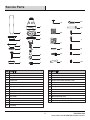
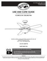
Service Parts
Please contact 1-855-HD-HAMPTON for further assistance.
MOC.YABNOTPMAH17
Blade screw
Fiber washer
Balance kit
Remote control holder mounting screws
Wire nuts
Hitch pin
Lock pin
Hanger ball set screw
Mounting bracket screw
Cross pin
Fan motor assembly coupling set screw
Fan motor assembly mounting ring screw
Light kit plate screw
Canopy cover
Hanger ball
Downrod
Blade
Mounting bracket
Canopy
Couping cover
17W LED assembly
Glass shade
Fan motor assembly
Light kit plate
Receiver
Remote control
12V Battery
Remote control holder
HH
LL
Part
AA
BB
CC
DD
EE
FF
GG
Description
Part
A
B
C
D
E
F
G
H
Description
L
JJ
II
KK
J
I
K
MMM
O
N
D
F
G
I
B
A
E
C
J
K
L
M
N
O
AA
BB
CC
DD
FF
EE
GG
HH
II
JJ
KK
LL
MM
H

Questions, problems, missing parts? Before returning to the store call
Hampton Bay Customer Service
8 a.m. - 6 p.m., EST, Monday-Friday
1-855-HD-HAMPTON
HAMPTONBAY.COM
Retain this manual for future use.

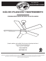
GUÍA DE UTILIZACIÓN Y MANTENIMIENTO
HAMPTONBAY.COM
COBRAM VENTILADOR DE TECHO DE 48 PULGADAS
¿Preguntas, problemas, partes perdidas? Antes de regresar al almacén por favor llame al
Servicios de Cliente de Hampton Bay por
8 a.m. - 6 p.m., EST, Lunes-Viernes
GRACIAS
Agradecemos la confianza de Hampton Bay a través de la compra del ventilador de techo. Nos esforzamos por crear los productos de calidad continuamente
para mejorar su casa. Por favor visítenos en línea para ver todas las líneas de nuestros productos disponibles para su necesidad.
¡Gracias a su selección de Hampton Bay!
Ítem #609-619
Modelo #CF548KR-CL160 (BN)
1-855-HD-HAMPTON

2
Información de Seguridad
□ Para reducir el riesgo de eléctrocución, asegurarse de que la
eléctricidad se ha desactivado en el cortacircuitos o caja de
fusibles antes de comen-zar.
□ Lea y guarde estas instrucciones.
□ Todos los cables deben cumplir con el Código Eléctrico Nacional
“ANSI/NFPA 70-1999” y los códigos eléctricos locales. La
instalación eléctrica debería realizarla un electricista profesional
cualicado.
□ La caja de distribución y la estructura de soporte deben estar
montados de manera segura y deben ser capaces de soportar, de
manera conable, unminimo de 35 libras (15,9 kilogramos). Usar
solamente cajas de distribución listadas por U.L. marcadas "PARA
SOPORTEDE VENTILADORES".
□ EL ventilador debe estar montado con un m nimo de 7 pies (213cm)
de espacio libre desde el borde posterior de las aspas hasta el piso.
□ Para evitar lesiones personales o da os al ventilador y otros
articulos, tener cuidado al trabajar cerca del ventilador o al
limpiarlo.
□ No usar agua o detergentes al limpiar el ventilador o las aspas del
ventilador. Para la mayoria de los prop sitos de limpieza, un paño
seco o ligeramente humedecido será apropiado.
□ Tras realizar las conexiones eléctricas, los conductores empalmados
deberían girarse hacia arriba y meterse con cuidado en la toma de
corriente.
□ Los cables deberían separarse con el conductor a tierra y el conductor
de tierra del equipo por un lado de la toma de corriente y el conductor
no conectado a tierra en el otro lado de la toma de corriente.Todos los
tornillos deberían ser comprobados y revisados antes de la
instalación.
ADVERTENCIA: PARA REDUCIR EL RIESGO DE LESIONES
PERSONALES, NO DOBLAR LOS SOPORTES DE LAS ASPAS
(TAMBIEN LLAMADOS "REBORDES"), DURANTE EL MONTAJE O
DESPUES DE LA INSTALACIÓN
ADVERTENCIA: NO INSERTAR OBJETOS EN LA
TRAYECTORIA DE LAS ASPAS.
ADVERTENCIA: PARA REDUCIR EL RIESGO DE FUEGO,
DESCARGA ELÉCTRICA O LESIONES PERSONALES, MONTE EL
VENTILADOR A UNA TOMA DE CORRIENTE MARCADA COMO
COMPATIBLE PARA SOPORTAR UN VENTILADOR CON LOS
TORNILLOS INCLUIDOS EN LA TOMA DE CORRIENTE.
PRECAUCIÓN: Para reducir el riesgo de lesiones personales,
utilice solamente los tornillos incluidos con la toma de corriente.
Lista de Contenidos
14
14
16
14
Operación
Cuidado y Limpieza 15
Solución de averías 16
Partes de Servicios 17
Instrucciones de operación de control remoto
Instrucciones de operación de botón de función inversa
Instalación del soporte del control remoto
.....................................................................
.................
..
......................
.....................................................
.....................................................
.....................................................
Instalación
Lista de Contenidos 2
Información de Seguridad 2
Garantía 3
Instalación Previa
Especicaciones
Herramienta Necesarias
Herramientas Incluidas
Contenidos de Paquete
3
3
3
4
5
6
Ensamblado
Colgar el ventilador
Fije las hojas de ventilador
Instale el Conjunto de Luz
7
7
12
13
.....................................................
...........................................
........................................................................
.........................................................
.........................................................
...............................................
................................................
.................................................
....................................................................
..................................................................
.....................................................
..........................................
............................................
NOTA: Está adecuado a la utilización con los controles de
velocidad de estado sólido.

MOC.YABNOTPMAH3
Por favor entre en contacto con 1-855-HD-HAMPTON para más ayuda.
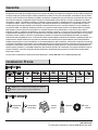
Especicaciones
Herramienta necesarias
Destornillador
de Phillips
Cinta
eléctrica
Pelacables Destornillador
de hoja plana
Escalera
de paso
NOTA: Estas son mediciones aproximadas. No incluyen los
Amperios y vatios usado por el juego de iliminación.
Garantía
Pre-InstallationInstalación Previa
Garantizamos que el motor del ventilador está libre de los defectos de calidad y de material por el tiempo de salir de la fábrica y después de
la fecha de compra por el cliente original. También garantizamos que todas las otras piezas del ventilador, excluyendo las hojas de vidrio o
de acrílico, cuales está libres de los defectos de calidad y de material en el momento de salir de la fábrica por un período de un año a partir
de la fecha de compra por el comprador original. Estamos de acuerdo de mejorar dichos defectos sin cargo o reemplazo por un modelo
comparable o superior si el producto es devuelto. Para obtener el servicio de garantía, usted debe presentar una copia de la factura como
una prueba de compra. Todos los gastos de desmontaje y reinstalación del producto son amumitidos por su responsabilidad. El daño a
cualquier pieza tales como por accidente, mala utilización, instalación incorrecta o por los accesorios adjuntivos, no están cubiertos por
esta garantía. Debido a las diferentes condiciones climáticas esta garantía no cubre ningún cambio en el acabado de bronce, incluyendo
óxido, picadura, corrosión, deslustre o descamación. Los acabados de bronce de este tipo brindan a la vida útil más larga cuando se
protege de las diversas condiciones meteorológicas. Una cierta cantidad de "oscilación " es normal y no debe considerarse como un defecto.
El mantenimiento realizado por las personas no autorizadas hará la garantía inválida. No hay ninguna otra garantía expresa. Por la presente
declaramos cualquier y todas las garantías, incluyendo pero no limitado a las garantías de comerciabilidad y dispinible a un propósito
particular del alcance permitido por la ley. La duración de cualquier garantía implícita no declarada está limitada al período especico en la
garantía expresa. Algunas declaraciones no permiten las limitaciones de la duración de una garantía implícita, por lo tanto la limitación
antedicha no puede aplicar a usted. Los detallistas no será responsable por los daños incidentales, consecuentes o especiales causados por
la utiliación o desempeño mal del producto, salvo el establecimiento por la ley. Algunas declaraciones no permiten la exclusión de los daños
incidentales o consecuentes, por lo tanto, la exclusión o limitación antedicha no puede aplicarse a usted. Esta garantía le proporciona los
derechos legales especícos, y usted también puede tener otros derechos diferentes de la declaración. Esta garantía reemplaza a todas las
garantías antedichas. Los gastos de despacho de todas devoluciones del producto como una parte de un reclamo de la garantía deben
pagarse por el cliente.
Por favor entre en contacto con el Grupo de Servicio de Cliente por 1-855-HD-HAMPTON o visite a www.hamptonbay.com.
48 in.
Baja
Mediana
Alta
120
Tamaño del
Ventilador
Vatios RPM CFMVelocidad Voltios Amperios
1.63 ft.
N.
W. G.W. C.F.
0.21
0.28
0.39
13.3
23.3
46.8
85
120
175
1873
2724
4102
6.52 kgs
(14.37lbs)
7.60 kgs
(16.76 lbs)

4
Tornillo de hoja
Arandela de bra (no a escala)
Conjunto de balanceo (no a escala)
Tornillos de montaje para soporte del mando a distancia
Tuerca de alambre plástica
Pasador de enganche (preassembled)
Pasado de bloqueo (no a escala) (premontado)
Tornillo de ajuste de bola de suspensión (premontado)
Tornillo de soporte de montaje (premontado)
El pasador transversal (no a escala) (premontado)
Tornillos de acoplamiento al motor del ventilador (premontado)
Tornillo de ensamblaje de anillo de motor del ventilador (premontado)
Instalación Previa (continuada)
HERRAMIENTAS INCLUIDAS
NOTA: Las medidas de las herramientas se demuestran en
la lista siguiente, salvo las otras observaciones.
AA
BB
CC
DD
EE
FF
GG
HH
II
JJ
KK
LL
MM
16
16
1
2
6
1
1
1
2
1
2
3
Tornillo de placa de juego de luz (premontado) 3
AA
BB
CC
DD
FF
EE
GG
HH
II
JJ
KK
LL
MM
Parte Descripción Cantidad

Por favor entre en contacto con 1-855-HD-HAMPTON para más ayuda.
MOC.YABNOTPMAH5
CONTENIDOS DE PAQUETE
Instalación Previa (continuada)
D
F
G
I
B
A
E
C
J
K
L
M
N
O
H
Tapa de cubierta (premontado)
Bola de suspensión (premontado)
Varilla
Hoja
Soporte de montaje
Tapa
Conjunto de motor de ventilador
Cubierta de acoplamiento
Conjunto LED 17W (premontado)
Sombra de vidrio
Placa de juego de luz (premontado)
Receptor
Mando a distancia
Batería 12V
Soporte de mando a distancia
D
E
F
1
1
1
A
B
C
5
1
1
H 1
G 1
L
M
N
1
1
1
I
J
K
1
1
1
O 1
Parte
Descripción Cantidad Parte Descripción Cantidad

6
Instalación
1
1
1
3
2
NOTA: Deberá tener una varilla más larga para
mantener adecuadamente limpias a las palas al instalar
en un techo inclinado. El ángulo máximo admisible es de
18˚. Si la cubierta toca la varilla, retire la tapa de botón
de cubierta decorativa, y gire la cubierta a 180˚ antes de
colocar la cubierta a la placa de montaje (2).
Si el ventilador de techo no hay una caja de montaje listada-UL
existente, instala una por utilizando las instrucciones siguientes:
□ Desconectar el suministro de electricidad removiendo los
fusibles o desactivando los cortacircuitos.
□ Asegurar la caja de distribución directamente a la estructura
del edicio. Usar los sujetadores y meteriales de construcción
apropiados. La caja de distribución y su soporte deben ser
capaces de soportar completamente el peso en movimiento
del ventilador (al menos 35 libras o 15,9 kgs.) No usar cajas de
distribución plásticas.
□ Para colgar el ventilador donde hay un equipo existante pero
no vigueta de techo, usted necesita una barra de percha de
instalación (3) (no incluida) como se demuestra arriba.
□ Las ilustraciones a la derecha muestran tres formas diferentes
para montar la caja de salida (no incluido).
ADVERTENCIA: Para reducir los peligrosos de fuego,
choque eléctrico o las lesiones personales, por favor monte el
ventilador en una caja de salida disponible al soporte de
ventilador utilizando los tornillos proporcionados con la caja
de salida. Generalmente una caja de salida que se utiliza para
el soporte de los equipos de iluminaciones no puede ser
disponibles al soporte de ventilador y debe reemplazarse.
Si hay dudas, por favor consulte a un electricista cualicado.
OPCIONES DE MONTAJE

Por favor entre en contacto con 1-855-HD-HAMPTON para más ayuda.
MOC.YABNOTPMAH7
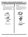
Ensamblado – Colgar el ventilador
1
Colocar el soporte de montaje a la
caja eléctrica
□
Aoje los dos tornillos de jación (JJ) del acoplamiento
del conjunto del motor del ventilador del motor (H).
□
Quite el pasador de enganche (GG) y el pasador de
bloqueo (HH) de la varilla (F). Quite la bola de suspensión
(E) de la varilla (F) por aojando el tornillo de jación de
la bola de suspensión (II), y quitando el pasador
transversal (FF), entonces deslizando la bola de
suspensión (E) fuera de la varilla (F).
□
Proporcione los cables del ventilador a través de la varilla
(F) cuidadosamente. Enrosque la varilla (F) en el
acoplamiento del conjunto del motor del ventilador (H).
Alinee los agujeros y reemplace el pasador de bloqueo
(HH) y el pasador del enganche (GG). Entonces apriete los
tornillos de jación (JJ).
B
Colocar la varilla al juego de
ensamblaje del motor del ventilador
2
ADVERTENCIA: PARA REDUCIR EL RIESGO DE FUEGO,
DESCARGA ELÉCTRICA O LESIONES PERSONALES, MONTE EL
VENTILADOR A UNA TOMA DE CORRIENTE MARCADA COMO
COMPATIBLE PARA SOPORTAR UN VENTILADOR CON LOS
TORNILLOS INCLUIDOS EN LA TOMA DE CORRIENTE.
□
Fije la soporte de montaje (B) a la caja de salida con dos
tornillos y arandelas suministrados con la caja de salida.
Asegúrese de que la soporte de montaje (B) este
apretada y asegurada.
JJ
GG
FF
F
E
II
HH
H

8
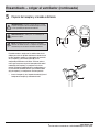
3
Colocar bién la tapa de acoplamiento,
la tapa de cubierta y la misma a la
varilla
Ensamblado – colgar el ventilador (continuada)
□
Deslice la cubierta de acoplamiento (G), la tapa de cubierta
(D), y la tapa (C) en la varilla (F). Y vuelva a instalar la bola
de suspensión (E) cuidadosamente en la varilla (F),
entonces por favor asegúrese de que el pasador
transversal (FF) esté en la posición correcta, los tornillos de
jación (II) estén apretados, y los alambres no sean
torcidos.
4
Cuelgueel juego de ensamblaje de
motor de ventilador desde el soporte
de montaje
□
Levante el conjunto del motor del ventilador (H) en la
posición, y coloque la bola de suspensión (E) en el soporte
de montaje (B). Gire el conjunto del motor del ventilador (H)
hasta que la ranura de prueba estén en la ranura de
registro (NN) y lo coloque rmemente. Debe girar la varilla
(F) en caso de falla operación.
F
NN
F
II
FF
B
G
E
C
D
E
H

Por favor entre en contacto con 1-855-HD-HAMPTON para más ayuda.
9 HAMPTONBAY.COM
Ensamblado – colgar el ventilador (continuada)
Preparar del receptor y el mando a distancia
5
El control remotor se equipa con las combinaciones de 16
códigos para evitar las posibles interferencias desde o hacia
los otros controles remotos. Los interruptores de frecuencia
de su receptor (L) y del control remoto (M) se han
congurado previamente en la fábrica. Por favor, vuelva a
revisar para asegurarse de que los interruptores del control
remoto (M) y del receptor (L) se congure en la misma
posición. Cualquiera combinación de las conguraciones se
va a funcionar el ventilador mientras que el control remoto
(M) y el receptor (L) se conguren en la misma posición.
□
Inserte el receptor (L) en el soporte de montaje (B) con el
lado plano del receptor (L) afrontando al techo.
PRECAUCIÓN: No lo utilice junto con un interruptor de
atenuación en pared
NOTA: Si usted le parece que no tenga un conocimiento
suciente de cableado eléctrico o la experiencia, deberá dejar
ser instalado por un electricista autorizado al ventilador.
ADVERTENCIA: Para evitar el choque eléctrico, por favor
asegúrese de apagar la electricidad del interruptor de circuito
o de la caja fusible principal antes del cableado.
M
L
L
B

10
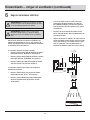
Ensamblado – colgar el ventilador (continuada)
6
Haga las conexiones eléctricas
Siga los pasos siguientes para conectar el ventilador a los
alambres de alimentaciones de su casa. Fije las tuercas de
alambre (EE) proporcionadas con el ventilador por envolviendo
las conexiones con la cinta eléctrica.
Las conexiones eléctricas del motor al receptor:
□ Conecte el alambre negro (CCC) del ventilador al alambre
negro (GGG) marcado "TO MOTOR L" del receptor (L).
□ Conecte el alambre blanco (AAA) del ventilador al alambre
blanco (EEE) marcado "TO MOTOR N" del receptor (L).
□ Conecte el alambre azul (BBB) del ventilador al alambre
azul (FFF) marcado "For Light" del receptor (L).
Las conexiones eléctricas del receptor a los alambres de
alimentación de vivienda:
□ Conecte el alambre negro (JJJ) del techo al alambre
negro (HHH) marcado " AC in L" del receptor (L).
□ Conecte el alambre blando (neutral) del alambre (KKK)
del techo al alambre blanco (III) marcado " AC in N"
del receptor (L).
□ Si la caja de salida (1) tiene un cable a tierra (LLL)
(verde o barra de cobre) conéctelo a los cables de
tierra (DDD)del ventilador, de lo contrario, conecte el
cable de tierra de la bola de suspensión (E) al soporte
de montaje (B).
□ Asegúrese de que la conexión del alambre con una
tuerca de alambre plástico (EE) sea proporcionada con
el hardware eléctrico.
□ Después de conectar los alambres, los separe con el n
de que los alambres verdes y blancos estén en un lado
de la caja de salida (1) y los alambres negros y azules
estén en el otro lado. Y meta cuidadosamente las
conexiones de alambres dentro de la caja de salida (1).
ADVERTENCIA: Para evitar el choque eléctrico, por favor
asegúrese de apagar la electricidad del interruptor de circuito
o de la caja fusible principal antes del cableado.
ADVERTENCIA: Verique todas las conexiones bien,
incluyendo el alambre a tierra, y no puede ver alambres
desnudos en las tuercas de alambre, excepto por alambre a
tierra.
1
ON
BBB
CCC
DDD
EEE
L
EE
FFF
GGG
HHH
III
JJJ
KKK
LLL
AAA

Por favor entre en contacto con 1-855-HD-HAMPTON para más ayuda.
11
HAMPTONBAY.COM
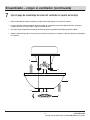
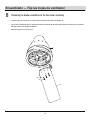
7
Fijar el juego de ensamblaje de motor del ventilador al soporte de montaje
□
Quite un tornillo (KK) del soporte de montaje (B) y aoje el otro tornillo (KK) por 1/4 de vuelta más o menos.
□
Levante la tapa (C) con mucho cuidado al soporte de montaje (B), y comprueba que el tornillo aojado (KK) haya insertado en
el agujero de la llave en la tapa (C). Gire la tapa (C) en sentido horario.
□
Fije la tapa (C) por reemplazando el tornillo (KK) previamente quitado y apretando el tornillo (KK) previamente aojado.
□
Coloque la cubierta de tapa (D) en la misma (C) y gire la cubierta de tapa (D) en el sentido de la aguja del reloj hasta que él bloquée
en su posición.
Ensamblado – colgar el ventilador (continuada)
KK
KK
C
D
B

12
Ensamblado — Fije las hojas de ventilador
□
Inserte las hojas (A) a través de las ranuras encima del conjunto del motor del ventilador (H).
□
Fije las hojas del ventilador (A) en el conjunto del motor del ventilador (H) por utilizando los tornillos de hoja (AA) y la arandela de
bra (BB), entonces los aprieten fuertemente.
□
Repita el paso para las otras hojas (A).
Fastening the blade assemblies to the fan motor assembly
8
H
A
AA
BB

Por favor entre en contacto con 1-855-HD-HAMPTON para más ayuda.
13
HAMPTONBAY.COM
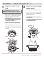
Ensamblado — Instale el Conjunto de Luz
PRECAUCIÓN: Para reducir el peligro del choque
eléctrico, por favor desconecte el circuito de alimentación
eléctrica al ventilador antes de la instalación del juego de luz.
Instalación de la placa de juego
de luz
9
□
Quite el conjunto LED 17W (J) de la placa de juego de luz
(I) por sacando los tres tornillos de placa de juego de luz
(MM). Y coloque los tornillos (MM) al lado para la
utilización en la futura.
□
Coloque los agujeros de llave de la placa de juego de
luz (I) encima de los dos tornillos (LL) aojados
previamente del anillo de montaje del conjunto del
motor del ventilador (H). Gire la placa de juego de luz (I)
hasta que él bloquée en el lugar en la sección estrecha
de los agujeros de llave. Los je por apretando los dos
tornillos (LL) aojados previamente y un tornillo sacado
previamente.
□
Quite uno de los tres tornillos (LL) del anillo de montaje
del conjunto del motor del ventilador (H) y aoje, pero
no saque, los otros dos tornillos (LL).
Instalación del conjunto LED 17W
y sombra de vidrio
10
I
K
MM
I
J
I
LL
H
□
Sosteniendo la conjunto LED 17W (J) bajo el ventilador,
se encajan las clavijas de conexión de cables (OO).
□
Coloque el conjunto LED 17W (J) en la placa de juego
de luz (I) y asegúrese de que los agujeros de tornillo
se alineén adecuadamente.
□
Fije el conjunto LED 17W (J) por reemplazando los tres
tornillos (MM) sacados previamente. Aprieten todos los
tornillos fuertemente.
□
Fije la sombra de vidrio (K) en la placa del conjunto de
luz (I) por torciendo fuertemente.
MM
I
J
H
OO

14
NOTA: Para utilizar la función inversa de este ventilador,
presione el botón de función inversa cuando el ventilador está
en funcionamiento.
Clima cálido - (Adelante) Una corriente de aire descendente crea un
efecto refrescante como se muestra en. Esto le permite ajustar su
aire acondicionado en un mayor ajuste sin que ello afecte su
comodidad.
Clima Frío - (Inversa) Un ujo de aire mueve el aire caliente hacia
arriba fuera de la zona límite, como se muestra en. Esto le permite
congurar su unidad de calefacción en un ajuste más bajo sin
afectar a su comodidad.
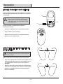
Operación
M
O
PP
Instrucción de operación de mando a distancia
INSTRUCCIONES DE OPERACIÓN DEL BOTÓN DE
FUNCIÓN INVERSA
Instale una batería de 12V (O) en el control remoto (M). Para evitar los
daños del control remoto, por favor quita la batería si no la utiliza por
un largo tiempo.
Botones de HI, MED, LOW : ajusta la velocidad del ventilador.
Botón de FAN OFF: apaga el ventilador.
Botón de luz: Activa o desactiva la luz . Mantenga pulsado el
botón para ajustar el brillo deseado.
□
□
□
Recupere a encender el ventilador de techo y pruebe el
funcionamiento adecuado.
□
□
Botón de función inversa (PP): Controla la dirección del ventilador.
ADVERTENCIA: No debe cortocircuito, desmontar,
calentar, conectar incorrectamente o dejar las baterías
usadas al fuego. No debe recargar ni mezclar las baterías
con las usadas o de otros tipos. Y debe quitar las baterías
usadas inmediatamente.

Por favor entre en contacto con 1-855-HD-HAMPTON para más ayuda.
15
MOC.YABNOTPMAH
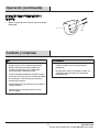
Operación (continuada)
N
DD
INSTALACIÓN DEL SOPORTE DE MANDO A
DISTANCIA
□
Coloque el soporte del mando a distancia (N) con dos tornillos
adjuntos (DD).
Cuidado y Limpieza
□ Verique las conexiones de soporte, soportes y equipos de
hoja dos ves por un año. Y asegúrese de jarlos bien.
Debido al movimiento natural del ventilador, unas
conexiones puedan aojarse por un tiempo. No es
necesario de quitar el ventilador del techo.
□ Limpie el ventilador periódicamente. Sólo utilice un paño
suave o libre de hilas para evitar la rascadura del acabado.
El revestimiento se selle con barniz para minimizar la
descoloración o deslustre.
□ (Opcional) Aplique una capa ligera de lustre de mueble en
las hojas de madera.
□ (Opcional) Cubre las rascaduras pequeñas con unos
lustres de zapatos.
Hacer
□ No pueda utilizar aguas a la limpieza. El agua pueda dañar
el motor, la madera o causar un choque eléctrico
posiblemente.
□ No pueda aplicar aceite en el ventilador o el motor. Los
rodamientos de bolas del motor han sido lubricados
permanentemente.
No pueda hacer

16
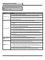
No conecte el ventilador con el controlador de velocidad montado en la pared (s).
Asegúrese de que los interruptores del mando a distancia y el receptor están en la misma frecuencia.
□
□
Verique si todas las hojas y los tornillos de brazo de hoja sean jados.
□ La mayoría de los problemas sobre la oscilación es causada cuando los niveles de hoja son irrgulares.
Verique el nivel por seleccionando un punto del techo encima del extremo de una de las hojas. Y tome
la medidas desde un punto en el centro de caja hoja al punto del techo. Gire el ventilador hasta que la
hoja siguiente sea situada para la medida. Repite por caja hoja. La desviación de las medidas debe estar
dentro de 1/8 pulgadas. Y funcione el ventilador por diez minutos.
Utilice el conjunto de balanceo de hoja adjuntivo si la oscilación de hoja todavía es notable.
Las oscilaciones de
ventilador
Solución de averías
Problema Solución
□ Revisar los fusibles o interruptores de circuitos.
□ Vericar las conexiones de cables de linea al ventilador y conexiones de cable del interruptor.
□ Revise los interruptores de frequencia del receptor y transmisor, los interruptores de las dos unidades
debén de estar en las mismas posiciones. Cambie la frequencia para descartar que su ventilador tenga
interferencia con otra unidad.
□ Asegurarse de que todos los tornillos de la cubierta del motor estén ajustados.
□ Asegurarse de que los tornillos que sujetan el soporte de aspas del ventilador al eje del motor estén
apretados.
□ Asegurarse de que las conexiones de tuercas para cable no esten rozando unas contra otras o contra la
pared interior de la cubierta protectora del interruptor.
□ Permitir un período de "desgaste" de 24 horas. La moyaría de los ruidos asociados con un ventilador
nuevo desaparecen durante este tirmpo.
□ Si se está usando un juego opcional de iluminación para el venitlador de techo, aseguarse de que los
tornillos que aseguran el vidrio estén apretados. Asimsmo, vericar que la bombilla esté segura.
□ Asegurarse de que el escudete superior esté a una corta distancia del techo. No debe hacer contacto
con el techo.
□ Asegúrese de que la caja del techo esté ja y que las almohadillas aislantes de goma estén colocadas
entre el soporte de montaje y la toma de corriente.
El ventilador no funciona
El ventilador emiteruido
El mando a distancia no
funciona.
ADVERTENCIA: Asegúrese de que la fuente eléctrica se
apague en la caja de panel eléctrico antes de hacer las
reparaciones. Y reérase a la sección de ¨Hacer las Conexiones
Eléctricas¨ en la págia 10.

Por favor entre en contacto con 1-855-HD-HAMPTON para más ayuda.
MOC.YABNOTPMAH17
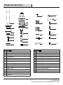
Partes de Servicios
Tornillo de hoja
Arandela de bra
Conjunto de balanceo
Tornillos de montaje para soporte del mando a distancia
Tuerca de alambre plástica
Pasador de enganche
Pasado de bloqueo
Tornillo de ajuste de bola de suspensión
Tornillo de soporte de montaje
El pasador transversal
Tornillos de acoplamiento al motor del ventilador
Tornillo de ensamblaje de anillo de motor del ventilador
Tornillo de placa de juego de luz
Tapa de cubierta
Bola de suspensión
Varilla
Hoja
Soporte de montaje
Tapa
Conjunto de motor de ventilador
Cubierta de acoplamiento
Conjunto LED 17W
Sombra de vidrio
Placa de juego de luz
Receptor
Mando a distancia
Batería 12V
Soporte de mando a distancia
HH
LL
AA
BB
CC
DD
EE
FF
GG
A
B
C
D
E
F
G
H
L
JJ
II
KK
J
I
K
MMM
O
N
D
F
G
I
B
A
E
C
J
K
L
M
N
O
AA
BB
CC
DD
FF
EE
GG
HH
II
JJ
KK
LL
MM
H
Parte ParteDescripción Descripción

1-855-HD-HAMPTON
HAMPTONBAY.COM
¿Preguntas, problemas, partes perdidas? Antes de regresar al almacén por favor llame al
Servicios de Cliente de Hampton Bay por
8 a.m. - 6 p.m., EST, Lunes-Viernes
Por favor mantenga el manual para la utilización en el futuro.
-
 1
1
-
 2
2
-
 3
3
-
 4
4
-
 5
5
-
 6
6
-
 7
7
-
 8
8
-
 9
9
-
 10
10
-
 11
11
-
 12
12
-
 13
13
-
 14
14
-
 15
15
-
 16
16
-
 17
17
-
 18
18
-
 19
19
-
 20
20
-
 21
21
-
 22
22
-
 23
23
-
 24
24
-
 25
25
-
 26
26
-
 27
27
-
 28
28
-
 29
29
-
 30
30
-
 31
31
-
 32
32
-
 33
33
-
 34
34
-
 35
35
-
 36
36


Hampton Bay CF548KR-160 BN Guía de instalación
- Categoría
- Ventiladores domésticos
- Tipo
- Guía de instalación
En otros idiomas
Documentos relacionados
-
Unbranded CF548KR-CL160OB Guía de instalación
-
 Hampton Bay 26612 Guía de instalación
-
 Hampton Bay 57231 Guía de instalación
-
 Hampton Bay 68042 Guía de instalación
-
 Hampton Bay 51353 Guía de instalación
-
 Hampton Bay 99913 Instrucciones de operación
-
 Hampton Bay 41359 Guía de instalación
-
 Hampton Bay 51548 Guía de instalación
-
 Hampton Bay 221809 Instrucciones de operación


