tekmar 553 guía de instalación rápida

Tipo
guía de instalación rápida

Este manual también es adecuado para

© 2014 553_Q - 02/14
1
A Watts Water Technologies Company
Interior
Wall
5 feet
1.5 m
Exterior
Wall
1. Location
2. Remove Mounting Base
3. Install Mounting Base
3
1
/4
(83 mm)
Thermostat
Base
Stud
Gang
Box
Wall
Stud
Thermostat
Base
Behind
Door
tekmarNet
®
Thermostat 553
Quick Setup Guide
553
_
Q
02/14
Zoning
Replaces: 01/14
© 2014 553_Q - 02/14
2
A Watts Water Technologies Company
4. Switch Settings
5. Wiring
Switch
Position
Action
1
ON
LOCK Access level
adjustment is not available.
OFF
UNLOCK Access level
adjustment is available.
tekmarNet
Thermostat 553
Two Stage Heat, One Stage Cool, Fan
Switch
Settings
www.tekmarcontrols.com
Lock
e
d
c
k
/
ON
1
2
Back of Thermostat
tekmarNet
®
4 Wiring Example
See 553_A for complete
wiring details.
W
R
Y
G
Optional
Outdoor
Sensor
070
Optional
Slab
Sensor
079
Furnace
and
Air Conditioner
tN4 Wiring Center
or Zone Manager
tN4 C W
R
C
tN2
tN4
tN2
R
Rh W Rc Y G/O S1 S2
ACC Com
No Power
W
R
Y
G
Optional
Outdoor
Sensor
070
Optional
Slab
Sensor
079
Furnace
and
Air Conditioner
tN2 Wiring Center,
House Control or
Zone Manager
tN2 tN2
C
tN2
tN4
tN2
R
Rh W Rc Y G/O S1 S2
ACC Com
No Power
tekmarNet
®
2 Wiring Example
© 2014 553_Q - 02/14
3
A Watts Water Technologies Company
6. Install the Thermostat
7. User Interface
Thermostat
Front
Push
Thermostat
Base
Adjust
the Time
Adjust the
Schedule
Display Humidity, Heat &
Cool settings, Floor or
Outdoor temperature
Away Key
Switch between
Auto, Heat,
Cool, Off &
Emergency Mode
Return to the
‘Home’ Screen
from any menu
Adjust the
Temperature
Room
Temperature
Turn the Fan on
Home
Button
All specifications are subject
to change without notice
4 553_Q - 02/14.
Product design, software and literature are Copyright ©2014 by tekmar Control Systems Ltd.,
A Watts Water Technologies Company. Head Offi ce: 5100 Silver Star Road, Vernon, B.C.
Canada V1B 3K4, 250-545-7749, Fax. 250-545-0650
Web Site
: www.tekmarControls.com
The following settings are essential to the successful operation of the system.
Step 1: Set switch setting #1 and tekmarNet
®
system control located in the mechanical
room to Unlock to change Access level to Installer. Return to Lock setting once installation
has been completed.
Step 2: Press and hold “Home” button for 3 seconds to enter programming menus.
Step 3: Touch NEXT to locate the Setup Menu and touch ENTER.
8. Critical Settings
Setup Menu Settings Range Default
SENSOR 1
Select the type of sensor connected to
auxiliary sensor input 1.
OFF, ROOM, FLOR
(floor), COIL, DUCT
OFF
SENSOR 2
Select the type of sensor connected to
auxiliary sensor input 2.
OFF, ROOM, FLOR
(floor), OUT (outdoor)
OFF
ROOM SENSOR
Select if the built-in room temperature
sensor is on or off.
OFF or ON ON
HUMIDITY SENSOR
Select if the built-in humidity sensor is
on or off.
OFF or ON ON
Y RELAY
Select the cooling equipment the Y relay
operates.
OFF, HP (heat pump),
AC (air conditioner), HUM
(humidity)
AC
W TERMINAL UNIT
Select the terminal unit type of the first
stage of heat W.
NONE, HRF1, HRF2,
CONV, COIL, FURN,
OTHR
HRF1 (tekmarNet
®
System Control)
OTHR (standalone)
ACC RELAY
Select the operation of the accessory
relay.
OFF, W2, HUM, DHUM,
HRV, FAN
W2
W2 TERMINAL UNIT
Select the type of backup heating.
CONV, COIL, FURN
(furnace), OTHR (other)
FURN
W2 SOURCE
Select the second stage W2 hydronic
heat source.
BOIL, TANK, MIX BOIL
G/O RELAY
Select the equipment the G / O relay
operates.
FAN or OFF
(conventional heating)
O or B (heat pump)
FAN (conventional)
O (heat pump)
For a full list of settings and operational details, please refer to the thermostat
Installation and Operation Manual (553_D) available from www.tekmarControls.com
© 2014 553_Q - 02/14
5
Une Entreprise de Watts Water Technologies
1. Emplacement
2. Retirez la base de montage
3. Installez la base de montage
3
1
/4
(83 mm)
Thermostat
Base
Stud
Gang
Box
Wall
Stud
Thermostat
Base
Derrière
porte
Mur extérieur
Mur intérieur
5 pi.
1,5 m
Mur
Base de
thermostat
Base de
thermostat
Commutateur
boîte
Goujon
Goujon
tekmarNet
®
Thermostat 553
Guide d'installation rapide
553
_
Q
02/14
Zonage
Remplace: 01/14
© 2014 553_Q - 02/14
6
Une Entreprise de Watts Water Technologies
W
R
Y
G
Optional
Outdoor
Sensor
070
Optional
Slab
Sensor
079
Furnace
and
Air Conditioner
tN4 Wiring Center
or Zone Manager
tN4 C W
R
C
tN2
tN4
tN2
R
Rh W Rc Y G/O S1 S2
ACC Com
No Power
4. Réglages des commutateurs
5. Filage
Commutateur Position Action
1
ON
VERROUILLAGE
Le réglage du niveau d'accès
n'est pas disponible.
OFF
DÉVERROUILLAGE
Le réglage du niveau d’accès est
disponible.
tekmarNet
Thermostat 553
Two Stage Heat, One Stage Cool, Fan
Switch
Settings
www.tekmarcontrols.com
Lock
e
d
c
k
/
ON
1
2
Dos du thermostat
tekmarNet
®
4 exemple de filage
Référence 553_A pour plus de
détails sur le filage complet.
W
R
Y
G
Optional
Outdoor
Sensor
070
Optional
Slab
Sensor
079
Furnace
and
Air Conditioner
tN2 Wiring Center,
House Control or
Zone Manager
tN2 tN2
C
tN2
tN4
tN2
R
Rh W Rc Y G/O S1 S2
ACC Com
No Power
tekmarNet
®
2 exemple de filage
Capteur
de dalle
079 (en
option)
Capteur
de dalle
079 (en
option)
Capteur
extérieur 070
(en option)
Capteur
extérieur 070
(en option)
Fourneau et
Climatiseur
Fourneau et
Climatiseur
tN4 contrôle des zones
tN2 contrôle des zones
© 2014 553_Q - 02/14
7
Une Entreprise de Watts Water Technologies
6. Installer le Thermostat
7. Interface d’utilisateur
Thermostat
Front
Push
Thermostat
Base
Home
Button
Régler
l’heure
Régler le
programme
Clè à
distance
Basculer entre
Auto, Chaud,
Frais, Off & mode
d’urgence
Régler la
température
Affichage de l’humidité,
des paramètres de
chaleur et du frais, de la
température
ambiante ou du sol
Température de la
chambre
Allumer la
ventillation
Bouton daccueil. Revenir à
l’écran «Home» (Accueil)
depuis n’importe quel menu.
Appuyez et maintenez
enfoncé pendant 3
secondes pour accéder aux
menus de programmation.
Base de
thermostat
Façade du
thermostat
Poussoir
Toutes sp
é
cifications sont sujettes à changements
sans préavis. Imprim
é
au Canada.
8 553_Q - 02/14.
Conception de produit, logiciel et littérature sont des droits réservés ©2014 par tekmar Control Systems
Ltd.,
Une Entreprise de Watts Water Technologies. Bureau Principal: 5100 Silver Star Road, Vernon,
B.C. Canada V1B 3K4, 250-545-7749, T
é
l
é
c: 250-545-0650
Site Web
: www.tekmarControls.com
Les paramètres suivants sont essentiels au bon fonctionnement du système.
Étape 1: Définir le réglage du commutateur sur #1 et le système de contrôle tekmarNet
®
situé
dans la salle mécanique sur Déverrouiller pour changer le niveau d’accès à l’installateur.
Retour pour Verrouiller réglage, une fois l’installation terminée.
Étape 2: Appuyez et maintenez le bouton «Home» pendant 3 secondes pour entrer dans
les menus de programmation.
Étape 3: Touchez SUIVANT pour localiser le menu de configuration et appuyez sur ENTRER.
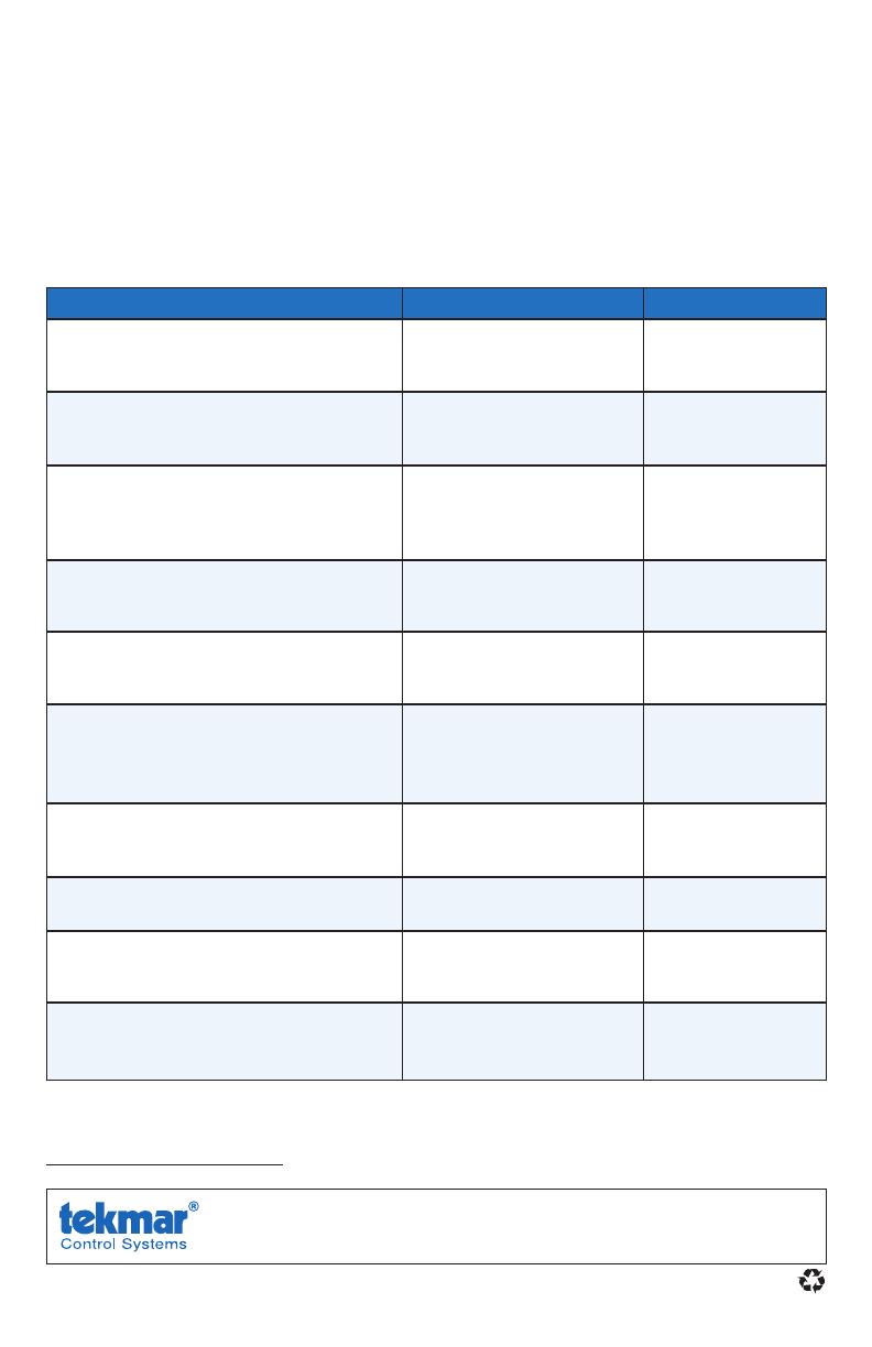
8. Paramètres critiques
Réglages du menu de configuration Gamme Par défaut
CAPTEUR 1
Sélectionner le type de capteur relié à
l’entrée auxiliaire du capteur 1.
OFF, ROOM, FLOR (sol),
COIL, DUCT
OFF
CAPTEUR 2
Sélectionner le type de capteur relié à
l’entrée auxiliaire du capteur 2.
OFF, ROOM, FLOR (sol),
OUT (en plein air)
OFF
CAPTEUR DE CHAMBRE
Sélectionnez si le capteur intégré de
la température ambiante est allumé ou
éteint.
OFF ou ON ON
CAPTEUR D'HUMIDITÉ
Sélectionnez si le capteur d'humidité
intégré est activé ou pas.
OFF ou ON ON
RELAIS Y
Sélectionnez l'équipement de refroidissement
que relais Y active.
OFF, HP (pompe à
chaleur), AC (climatiseur),
HUM (humidi)
AC
UNITÉ DU TERMINALE W
Sélectionnez le type d’unité du terminal
de la première étape de chauffage W.
NONE, HRF1, HRF2,
CONV, COIL, FURN, OTHR
HRF1 (tekmarNet
®
Contrôle de
Système)
OTHR (autonome)
RELAIS ACCESSOIRE
Sélectionnez l’appareil que le relais
accessoire active.
OFF, W2, HUM, DHUM,
HRV, FAN (ventilateur)
W2
UNITÉ DU TERMINALE W2
Sélectionnez le type de chauffage d'appoint.
CONV, COIL, FURN
(fourneau), OTHR (autre)
FURN
SOURCE DE W2
Sélectionnez la source de chaleur hydroniques
de la deuxième étape W2.
BOIL (ébullition), TANK
(réservoir), MIX (melange)
BOIL (ébullition)
RELAIS G/O
Sélectionnez l'équipement le relais G / O
est ouvert.
FAN (ventilateur) ou OFF
(chauffage conventionnel)
O ou B (pompe à chaleur)
FAN (ventilateur)
(classique)
O (pompe à chaleur)
Pour une liste complète des paramètres et les détails opérationnels, s’il vous plaît se
référer à l’installation du thermostat et mode d’emploi (553_D) disponible sur
www.tekmarControls.com
© 2014 553_Q - 02/14
9
Una Compañía de Watts Water Technologies
1. Ubicación
2. Quite la base de montaje
3. Instalación de la base de montaje
3
1
/4
(83 mm)
Thermostat
Base
Stud
Gang
Box
Wall
Stud
Thermostat
Base
Detrás
de la puerta
Pared
exterior
Pared
interior
5 pies
1,5 m
Base del
termostato
Base del
termostato
Pared
Caja de
interruptor
tekmarNet
®
Thermostat 553
Guía de instalación rápida
553_Q
02/14
División en
zonas
Remplazado
por: 01/14
© 2014 553_Q - 02/14
10
Una Compañía de Watts Water Technologies
4. Ajustes del interruptor
5. Cableado
Interruptor
Posición Acción
1
ON
LOCK (BLOQUEADO) el nivel
de acceso para ajustes se
encuentra bloqueado.
OFF
UNLOCK (DESBLOQUEADO)
el nivel de acceso para ajustes
se encuentra disponible.
tekmarNet
Thermostat 553
Two Stage Heat, One Stage Cool, Fan
Switch
Settings
www.tekmarcontrols.com
Lock
e
d
c
k
/
ON
1
2
Parte trasera del termostato
tekmarNet
®
4 ejemplo de cableado
Referencia 553_A para detalles
completos del cableado.
W
R
Y
G
Optional
Outdoor
Sensor
070
Optional
Slab
Sensor
079
Furnace
and
Air Conditioner
tN4 Wiring Center
or Zone Manager
tN4 C W
R
C
tN2
tN4
tN2
R
Rh W Rc Y G/O S1 S2
ACC Com
No Power
W
R
Y
G
Optional
Outdoor
Sensor
070
Optional
Slab
Sensor
079
Furnace
and
Air Conditioner
tN2 Wiring Center,
House Control or
Zone Manager
tN2 tN2
C
tN2
tN4
tN2
R
Rh W Rc Y G/O S1 S2
ACC Com
No Power
tekmarNet
®
2 ejemplo de cableado
Caldera y
acondicionador
de aire
Caldera y
acondicionador
de aire
tN4 control de
zonas
tN2 control de
zonas
Sensor de
exterior
opcional 070
Sensor de
exterior
opcional 070
Sensor de
losa opcional
079
Sensor de
losa opcional
079
© 2014 553_Q - 02/14
11
Una Compañía de Watts Water Technologies
6. Instalación del termostato
7. Interfaz del usuario
Thermostat
Front
Push
Thermostat
Base
Base del
termostato
Frente del
termostato
Eempuje
Home
Button
Ajustar
hora
Temperatura
ambiente
Prender el
ventilador
Botón Inicio. Vuelva
a la pantalla inicial
desde cualquier otro
menú. Mantenga
presionado por
3 segundos para
acceder al menú del
programa.
Ajustar la
programación
Tecla de salida
Ajustar la
temperatura
Elija entre Auto (Automático),
Heat (Calefacción),
Cool (Refrigeración),
Off (Apagado) y Emergency
Mode (Modo de emergencia)
Mostrar los ajustes de
humedad, calefacción
y refrigeración, la
temperatura del Piso
y Externa.
Todas las especificaciones pueden cambiar
sin previo aviso.
12 553_Q - 02/14.
El diseño del producto, software y la literatura poseen derechos reservados ©2014 a nombre de tekmar
Control Systems Ltd., Una Compañía de Watts Water Technologies Ofi cina Principal: 5100 Silver Star Road,
Vernon, B.C. Canadá V1B 3K4, 250-545-7749, Fax. 250-545-0650 Sitio web: www.tekmarControls.com
Las siguientes configuraciones son esenciales para que el sistema trabaje de manera correcta.
Paso 1: Desbloquee (opción UNLOCK) el ajuste número uno del interruptor y del control del sistema
tekmarNet
®
para cambiar el nivel de accesibilidad a Instalador. Cámbielo nuevamente a Bloquear (opción
Lock) luego de finalizar la instalación.
Paso 2: Mantenga presionado el botón “Home” por 3 segundos para ingresar a los menús de programación.
Paso 3: Presione el botón NEXT (SIGUIENTE) para localizar el menú de SETUP (Instalación) y presione
ENTER (ENTRAR).
8. Ajustes críticos
Ajustes del menú de instalación Rango Predeterminado
SENSOR 1
Seleccione el tipo de sensor conectado
a la entrada número 1 para sensor
auxiliares.
OFF, ROOM, FLOR (piso),
COIL, DUCT
OFF
SENSOR 2
Seleccione el tipo de sensor conectado
a la entrada número 2 para sensor
auxiliares.
OFF, ROOM (ambiente),
FLOR (piso), OUT (exterior)
OFF
SENSOR AMBIENTE
Prenda o apague el sensor integrado de
la temperatura del aire en el ambiente.
OFF o ON ON
SENSOR DE HUMEDAD
Seleccione si el sensor de humedad
integrado estará prendido o apagado.
OFF o ON ON
RELÉ Y
Seleccione el equipo de refrigeración que
accionara el relé Y.
OFF, HP (bomba de calor),
AC (acondicionador de
aire), HUM (humedad)
AC
TIPO DE TERMINAL W
Seleccione el tipo de unidad terminal de
la primera etapa de calefacción W.
NONE (Ninguna), HRF1,
HRF2, CONV, COIL, FURN,
OTHR
HRF1 (Sistema de
control
tekmarNet
®
)
OTHR (Otro)
RELÉ ADICIONAL
Seleccione el equipo que el relé adicional
accionará.
OFF, W2, HUM, DHUM,
HRV, FAN
W2
TIPO DE TERMINAL W2
Seleccione el tipo de calefacción de respaldo.
CONV, COIL, FURN
(caldera), OTHR (otro)
FURN
FUENTE W2
Seleccione la fuente de calefacción hidrónica
W2 de segunda etapa.
BOIL, TANK, MIX BOIL
RELÉ G/O
Seleccione el equipo que el relé G /O utiliza.
FAN (ventilador) o
OFF
(calefacción convencional)
O o B (bomba de
calefacción)
FAN (onvencional)
O (bomba de
calefacción)
Para una lista completa de ajustes y detalles funcionales, por favor diríjase al Manual de
Instalación y manejo del termostato (553_D) disponible en www.tekmarControls.com
  • Page 1 1
  • Page 2 2
  • Page 3 3
  • Page 4 4
  • Page 5 5
  • Page 6 6
  • Page 7 7
  • Page 8 8
  • Page 9 9
  • Page 10 10
  • Page 11 11
  • Page 12 12

tekmar 553 guía de instalación rápida

Tipo
guía de instalación rápida
Este manual también es adecuado para

En otros idiomas