Kenmore Elite 79077543805 Guía de instalación
- Categoría
- Microondas
- Tipo
- Guía de instalación

iNSTALLATiON AND SERVICE MUST BE PERFORMED BY A QUALiFiED iNSTALLER.
iMPORTANT: SAVE FOR LOCAL ELECTRICAL INSPECTOR'S USE.
READ AND SAVE THESE iNSTRUCTiONS FOR FUTURE REFERENCE.
if the information in this manual is not followed
exactly, a fire or explosion may result causing property
damage, personal injury or death.
FOR YOUR SAFETY:
= Do not store or use gasoline or other flammable vapors
and liquids in the vicinity of this or any other appliance.
= WHAT TO DO iF YOU SMELL GAS:
• Do not try to light any appliance.
• Do nottouch any electrical switch; do not use any phone
in your building.
• Immediately call your gas supplier from a neighbor's
phone. Follow the gas supplier's instructions.
• if you cannot reach your gas supplier, call the fire
department.
= Installation and service must be performed by a qualified
installer, service agency or the gas supplier.
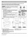
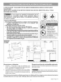
Refer to your serial plate for
applicable agency certification
• ALL RANGES
CAN TiP
• INJURYTO PERSONS
COULD RESULT
• iNSTALL ANTI=TIP
DEVICE PACKED WiTH
RANGE
• SEE iNSTALLATiON
iNSTRUCTiONS
Note: For appliances installed in the
State of Massachusetts see page 2.
OVERALL
DiMENSiONS
FRONT
47-3/4" Side of "5"-_Maximum 36 =+1/8" Range 5"
_1-==30,,_
*Minimum to -- 30"
Side Wall Minimum t Minimum to 1÷13"-_1
li Cabinets on Maximum Depth
on Either _ " Either Side for Cabinets
of Range. Above Range Top.
_---25"_
30" ----_1 0" Clearance Below Cooking Top and at Rear of Range,
Clearances and Dimensions
1. Location--Check location where the range will be
installed. Check for proper electrical and gas supply,
and the stability of the floor.
2. Dimensions that are shown must be used. Given
dimensions provide minimum clearance. Contact
surface must be solid and level.
Provide Proper Fuel Type
Before Proceeding: Your appliance was preset at the factory
to operate on Natural Gas only.
Note: For operation at elevations above 2000 ft., appliance rating shall be reduced at the rate of 4 percent for each
1000 ft. above sea level.
p/n 316259347(0807)
1

importantNotestotheInstaller
1. Read all instructions contained in these installation
instructions before installing range.
2. Remove all packing material from theoven compartments
before connecting the gas and electrical supply to the
range.
3. Observe allgoverning codes and ordinances.
4. Be sure to leave these instructions with the consumer.
important Note to the Consumer
1. Keep these instructions with your Use & Care Manual for
futu re reference.
IMPORTANT SAFETY INSTRUCTIONS
Installation of this range must conform with local codes or, in
the absence of local codes, with the National Fuel Gas Code
ANSI Z223.1--1atest edition when installed in the United
States.
When installed in a manufactured (mobile) home, installation
must conform with the Manufactured Home Construction and
Safety Standard, Title 24 CFR, Part 3280 [formerly the Federal
Standard for Mobile Home Construction and Safety, Title 24,
HUD (Part 280)] or, when such standard is not applicable, the
Standard for Manufactured Home Installations, ANSI/NCSBCS
A225.1, or with local codes.
This appliance has been design certified by CSA International.
Aswith any appliance using gas and generating heat, there are
certain safety precautions you should follow. You will find them
in the Use & Care Manual, read it carefully.
• Be sure your range isinstalled and grounded properly
by a qualified installer or service technician.
• This range must be electrically grounded in
accordance with local codes or, in their absence,
with the National Electrical Code ANSI/NFPA No .70--
latest edition when installed in the United States. See
Grounding Instructions on page 5.
• Before installing the range in an area covered with
linoleum or any other synthetic floor covering, make
sure the floor covering can withstand heat at least
90°F above room temperature without shrinking,
warping or discoloring. Do not install the range over
carpeting unless you place an insulating pad or sheet of
1/4-inch thick plywood between the range and carpeting.
• Make sure the wall coverings around the range can
withstand the heat generated by the range.
• Do not obstruct the flow of combustion airat the oven
vent nor around the base or beneath the lower front
panel of the range. Avoid touching the vent openings or
nearby surfaces as they may become hot while the oven
is in operation. This range requires fresh air for proper
burner combustion.
• Air curtain or other overhead range hoods, which operate
by blowing a downward airflow on to a range, shall not be
used in conjunction with gas ranges other than when the
hood and range have been desgined, tested and listed by
an independent test laboratory for use in combination with
each other.
Never leave children alone or unattended
in the area where an appliance is in use. As children grow,
teach them the proper, safe use of all appliances. Never leave
the oven door open when the range is unattended.
Stepping, leaning or sitting on the doors
or drawers of this range can result inserious injuries and
can also cause damage to the range.
• Do not store items of interest to children in the
cabinets above the range. Children could be seriously
burned climbing on the range to reach items.
• To eliminate the need to reach over the surface
burners, cabinet storage space above the burners
should be avoided.
• Adjust surface burner flame size so it does not
extend beyond the edge of the cooking utensil.
Excessive flame is hazardous.
• Do not use the oven as a storage space. This creates
a potentially hazardous situation.
• Never use your range for warming or heating the
room. Prolonged use of the range without adequate
ventilation can be dangerous.
• Do not store or use gasoline or other flammable
vapors and liquids near this or any other appliance.
Explosions or fires could result.
• Reset all controls to the "off" position after using a
programmable timing operation.
FOR MODELS WiTH SELF=CLEAN FEATURE:
. Remove broiler pan, food and other utensils before
self=cleaning the oven. Wipe up excess spillage. Follow
the cleaning instructions in the Use & Care Guide.
. Unlike the standard gas range, THiS COOKTOP IS
NOT REMOVABLE. Do notattempt to remove the cooktop.
Special instructions for appliances installed in the State of
Massachusetts: This appfiance can only be instafled in the
State of Massachusetts by a Massachusetts licensed
plumber or gas fitter. When using a flexible gas connector, it
must not exceed 3 feet (.36inches) in length. A "T" handle
type manual gas valve must be installed in the gas supply
line to this appfiance.
DO NOT MAKE ANY ATTEMPT TO
OPERATE THE ELECTRIC IGNITION OVEN DURING AN
ELECTRICAL POWER FAILURE. RESET ALL OVEN
CONTROLS TO "OFF" IN THE EVENT OF A POWER
FAILURE.
The electric ignitor will automatically re-ignite the oven burner
when power resumes ifthe oven thermostat control was left
in the "ON" position.
When an electrical power failure occurs during use, the
surface burners will continue to operate.
During a power outage, the surface burners can be lit with a
match. Hold a lighted match to the burner, then slowly turn
the knob to the LITE position. Use extreme caution when
lighting burners this way.

Before Starting
Tools You Will Need
For leveling legs and Anti=Tip Bracket:
• Adjustable wrench or channel lock pliers
• 5/16" Nutdriver or Flat Head Screw Driver __
• Electric Drill & 1/8" Diameter Drill Bit (5/32" Masonry Drill
Bit if installing in concrete)
For gas supply connection:
• Pipe wrench l_
For burner flame adjustment:
• Phillips head _ and
blade-type screwdrivers __::
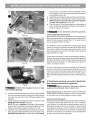
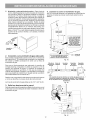
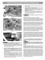
A. Locate the Bracket Using the Template - (Bracket may
be located on either the left or right side of the appliance. Use
the information below to locate the bracket if template is not
available). Mark the floor or wall where left or right side of the
rangewill be located. If rear of appliance is against thewall or
no further than 1-1/4" from wall when installed, you may use
the wall orfloor mount method. If molding isinstalled and does
not allow the bracket to fit flush against the wall, remove
molding or mount bracket to the floor. For wall mount, locate
the bracket by placing the back edge of the template against
the rear wall and the side edge of template on the mark made
referencing the side of the appliance. Place bracket on top of
template and mark location of the screw holes in wall. If rear
of appliance isfurther than 1-1/4" from thewallwhen installed,
attach bracket to the floor. For floor mount, locate the bracket
by placing back edge of the template where the rear of the
range will be located. Mark the location of the screw holes,
shown in template.
Additional Materials You Will Need
• Gas line shut-offvalve _:_:_.
• Pipe joint sealant
A new flexible metal appliance conduit (1/2" NPTx 3/4"
or 1/2" I.D.) must be design certified byCSA International.
Because solid pipe restricts moving the range we
recommend using a new flexible conduit (4 to 5 foot
length) for each new installation and additional
reinstallations.
• Always use the (2) new flare union adapters (1/2" NPT x
3/4" or 1/2" I.D.) supplied with the new flexible appliance
conduit for connection of the range.
Normal Installation Steps
1. Anti-Tip Bracket Installation Instructions
Important Safety Warning
To reduce the risk of tipping of the appliance, the range must
be secured to the floor by properly installed anti-tip bracket and
screws packed with the range. Failure to install the anti-tip
bracket will allow the range to tip over if excessive weight is
placed on an open door or if a child climbs upon it. Serious
injury might result from spilled hot liquids orfrom the appliance
itself.
If the appliance is ever moved to a different location, the anti-
tip brackets must also be moved and installed with the
appliance.
Instructions are provided for installation in wood or cement
fastened to either the floor or wall. When installed to the wall,
make sure that screws completely penetrate dry wall and are
secured in wood or metal. When fastening to the floor or wall,
be sure that screws do not penetrate electrical wiring or
plumbing.
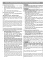
B=
Drill Pilot Holes and Fasten Bracket - Drill a 1/8" pilot
hole where screws are to be located. If bracket is to be
mounted to the wall, drill pilot hole at an approximate 20 °
downward angle. If bracket is to be mounted to masonry
or ceramic floors, drill a 3/16" pilot hole 1-3/4" deep. The
screws provided may be used inwood or concrete material.
Use a5/16" nut-driver orflat head screwd riverto secure the
bracket in place.
FASTEN BRACKET (WALLORFLOORMOUNTING)
=-_1 I,_==1=1/4'' Max.
LevelingLeg--
_I _F Wall M°unt
- J_:: _11 Plate
Floor Mount /--Anti-Tip Bracket
FASTEN BRACKET (FLOORMOUNTINGONLY)

C=
Level & Position Appliance- Leverappliance byadjusting
the (4) levering legs with a wrench. NOTE: A minimum
ctearance of 1/8" is required between the bottom of the
appliance and the levering leg to allow room for the
bracket. Use a spirit lever to check your adjustments.
Stide apptiance back into position. Visually check that
rear leveling leg is inserted into and fully secured by the
Anti-Tip Bracket by removing lower panel or storage
drawer. For modets with a warmer drawer or Bake-n-
Warm TMDouble Oven compartment, grasp the top rear
edge of the range and carefully attempt to titt itforward.
2. Provide an adequate gas supply.
This appliance is factory pre-set to operate on 4" natural gas
manifold pressure. A gas pressure regulator is connected to
the manifold and MUST be connected in series with the gas
supply line.
Care must be taken during installation of the appliance not to
obstruct the flow of combustion and ventilation air.
For proper operation, the maximum inlet pressure to the
regulator should be no more than 14 inches of water column
pressure. The inlet pressure to the regulator must be at least
1inch greater than regulator manifold pressure. Examples: If
regulator is set for natural gas 4 inch manifold pressure, inlet
pressure must be at least 5 inches.
Leak testing of the appliance shall be conducted according to
the instructions in step 4g.
The gas supply line should be 1/2" or 3/4" I.D.
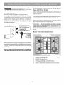
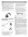
3. Seal wall openings.
Seal any openings inthe wall behind the appliance and in the
floor under the appliance after gas supply line is installed.
4. Connect the appliance to the gas supply.
NOTE: To prevent leaks use pipe joint sealant on all male
(outside) pipe threads.
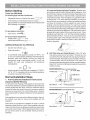
/
J ii
:;e,oe
of _ange
--_ 11-1/2" _--
I
_Recommended Area for_ i
|120V Outlet on Rear of I
i |Wall and Area for Thru|
_the Wall Connection of|l
iPipe Stub and Shut Off|
!_ Valve is Shaded Area. j
I
!
o2"i i
Pipe Stub and Shut Off Valve.
Fig. 4a
- .4t Wall
Edge
Manual Flare Flexible Flare Union Pressure
Shutoff Union Appliance Adaptor Regulator
Valve / Conduit !
Off
ServiceShut-Off Valve Electric Ignition models onl_'-''4'_lc,,_,ny__
(Shown in ON Position).
Besure lever is in the "On" position when
installation is complete
Fig. 4b
Gas
Regulator
o o
Gas i
Regulator I_
Gas Shut-Off Valve
(shown in the
"ON" position,)
Fig. 4c
2

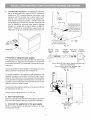
Fig. 4d
Fig. 4e
Fig. 4f
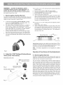
d)
e)
t)
g)
the 1/2" flare union adapter with an adjustable wrench
before tightening the gas supply fitting and/or appliance
conduit (Refer to Fig. 4e).
Installflare union adapter to external manual shut-offvalve.
Attach appliance conduit to flare union on shut-off valve.
Make sure service shut=offvalve on pressure regulator
is in the "ON" position (See Fig. 40.
Check for leaks. Turn the gas supply on to the appliance
and use a liquid leak detector at all joints and conduits to
check for leaks in the system.
Do not use flame to check for gas leaks.
Checking Manifold Gas Pressure
Disconnect the range and itsindividual shut-offvalve from the
gas supply piping system during any pressure testing of that
system at test pressures greater than 14" of water column
pressure (approximately 1/2" psig).
The appliance must be isolated from the gas supply piping
system by closing its individual manual shut-off valve during
any pressure testing of the gas supply piping system at test
pressures equal to or less than 14" of water column pressure
(approximately 1/2" psig).
DO NOT allow regulator to turn on pipe
when tightening fittings.
a) Install an external manual gas shut-offvalve to gas supply
line in an accessible location outside of the range. Be sure
you know where and how to shut off the gas supply to the
appliance.
b) Install l/2"flareunionadaptertopressureregulatorusing
NO MORE THAN 15ft./Ibs. of torque
NOTE: Be sure to stabilize the left side of the pressure
regulatorwith adjustablewrench before tightening ANY
fittings to the pressure regulator (Refer to Fig. 4d).
c) Tighten the gas supply fitting and/or appliance conduit to
flare union on the right sideofthe pressure regulator using
NO MORE THAN 15ft./Ibs. oftorque. Be sure tostabilize
If itshould be necessary to check the manifold gas pressure,
connect manometer (water gauge) or other pressure device to
thetop burner right rear orifice. Using a rubber hosewith inside
diameter of approximately 1/4," hold tubing down tight over
orifice. Turn burnervalveon.
For an accurate pressu re check have at least two (2) other top
burners burning. Be sure the gas supply (inlet) pressure is at
least one inch above specified range manifold pressure. The
gas supply pressure should never be over 14" water column.
When properly adjusted for Natural Gas the manifold pressure
is 4."
5
5. Read these electrical connection details first
then connect electricity to appliance.
Before servicing, disconnect electrical
supply at circuit breaker, fuse or power cord.
Electric Requirements: A dedicated, properly grounded and
polarized branch circuit protected by a 15 amp. circuit breaker
or time delay fuse. See serial plate for proper voltage.
Extension Cord Precautions:
Because of potential safety hazards under certain conditions,
we strongly recommend against the use of any extension
cord. However, if you still elect to use an extension cord, it is
absolutely necessary that it be a UL listed 3-wire grounding
type appliance extension cord and that the current carrying
rating of the cord in amperes be equivalent to or greater than
the branch circuit rating. Such extension cords are obtainable
through your local service organization.

PLEASEREADCAREFULLY!Forpersonal
safety,thisproductmustbeproperlygrounded.
GroundingInstructions
The power cord of this appliance is equipped with a
3-prong (grounding) plug which mates with a standard
3-prong grounding wall receptacle to minimize the possibility
of electric shock hazard from this appliance. The customer
should have the wall receptacle and circuit checked by a
qualified electrician to make sure the receptacle is properly
grounded and polarized.
Preferred
Do Not, Under
Power Supply
Grounding Cord with
Type 3=Prong
Wall Grounding
Receptacle Plug
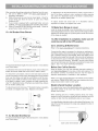
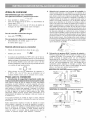
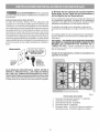
6.Assembly of the Surface Burner Heads, Burner
Caps and Burner Grates:
It isvery important to make sure that all of the Surface Burner
Heads, Surface Burner Caps and Surface Burner Grates are
installed correctly.
Your appliance was shipped with the burner heads and burner
caps assembled in the correct locations (See Fig. 1).
Should you need to re-install the burner caps please refer to
the Use & Care Guide for more information.
REMEMBER--DO NOTALLOW SPILLS, FOOD, CLEANING
AGENTS ORANY OTHER MATERIAL TO ENTER THE GAS
ORIFICE HOLDER OPENING. Always keepthe Burner Caps
and Burner Heads in place whenever the surface burners are
in use.
Burner sizes and cooktop locations
Where a standard two-prong wall receptacle is encountered,
it isthe personal responsibility and obligation of the customer
to have it replaced with a properly grou nded three-prong wall
receptacle.
DO NOT,UNDERANY CIRCUMSTANCES, CUT ORREMOVE
THE THIRD (GROUND) PRONG FROM THE POWER CORD.
1. 5,000 BTU Simmer Burner. Fig. 1
2. 9,500BTU Bridge Burner.
3. 9,500 BTU Power Burner(some models).
4. 14,200 BTU Power Burner (some models).
5. 3,000 to 18,000 BTU Double Burner (some models).

REMEMBER-- DONOTALLOWSPILLS,FOOD,
CLEANINGAGENTS OR ANY OTHER MATERIAL TO
ENTER THE GAS ORIFICE HOLDER OPENING. Always
keep the Burner Caps and Burner Heads in place whenever
the surface burners are in use.
7. Electric Ignition Surface Burners
Operation of electric igniters should be checked after range and
supply line connectors have been carefully checked for leaks and
range has been connected to electric power.
a. To check for proper lighting, push in and turn a surface
burner knob counterclockwise to the Lite position. You
will hear the igniter sparking (See Fig. 1).
b. The surface burner should light when gas is available to
the top burner. Purge air from supply lines by leaving
knob in the Lite position until burner ignites. Each burner
should light within four (4) seconds in normal operation
after air has been purged from supply lines.
c. Visually check that burner has lit. Once the burner lights,
the control knob should be turned out of the Lite position.
d. There are separate electrodes (igniters) for each burner.
Try each knob separately until all burner valves have been
checked.
Test to verify if '%0 or LOW" setting should be adjusted (right front
position ONLY):
a. Push in and turn knob to Lite until burner ignites.
b. Push in and quickly turn knob to LOWEST POSITION.
c. If burner goes out, reset control to OFF.
d. Remove the burner control knob.
e. Use a thin-bladed screwdriver and adjust the inner burner
flame size with the right-hand set screw (See Fig. 2). Adjust
the outer burner flame size with the lower set screw (See Fig.
2). Turn counterclockwise to increase flame size. Turn
clockwise to decrease flame size.
Test to verify if "LO or LOW" setting should be adjusted (all other
positions):
a. Follow steps a thru d above.
b. Insert a thin-bladed screwdriver into the hollow valve stem
and engage the slotted screw inside (Fig. 3). Flame size can
be increased or decreased with the turn of the screw. Turn
counterclockwise to increase flame size. Turn clockwise to
decrease flame size.
Burner Flame Size
5/8" ,_--
Main
Top
Fig. 1
8. Adjust the "LOW" Setting of Surface Burner
Valve (Linear Flow Valves)"
Riqht-hand burner only
Fig. 2
Outer burner flame
adjustment screw
All other surface burners
Inner burner flame
adjustment screw
Fig. 3
J
Adjust flame until you can quickly turn knob from LITE to
LOWEST POSITION without extinguishing the flame. Flame
should be as small as possible without going out.
Note: Air mixture adjustment is not required on surface
burners.
Operation of Oven Burners & OvenAdjustments
9. Electric Ignition Burners
Operation of electric igniters should be checked after range and
supply line connectors have been carefully checked for leaks and
range has been connected to electric power.
The oven burner is equipped with an electric control system as
well as an electric oven burner igniter. If your model is equipped
with a waist-high broil burner, it will also have an electric burner
igniter. These control systems require no adjustment. When the
oven is set to operate, current will flow to the igniter. It will "glow"
similar to a light bulb. When the igniter has reached a temperature
sufficient to ignite gas, the electrically controlled oven valve will
open and flame will appear at the oven burner. There is a time
lapse from 30 to 60 seconds after the thermostat is turned ON
before the flame appears at the oven burner. When the oven
reaches the dial setting, the glowing igniter will go off. The burner
flame will go "out" in 20 to 30 seconds after the igniter goes "OFF."
To maintain any given oven temperature, this cycle will continue
as long as the dial (or display) is set to operate.

Afterremovingallpackingmaterialsandliteraturefromtheoven:
a) Setovento BAKEat300°F.SeeUse & Care Manual for
operating instructions.
b) Within 60 seconds the oven burner should ignite. Check for
proper flame and allow the burner to cycle once. Reset
controls to OFF.
c) If your model is equipped with a waist-high broiler, set oven
to BROIL. See Use & Care Manual for operating instructions.
d) Within 60 seconds the broil burner should ignite. Check for
proper flame. Reset controls to OFF.
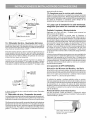
10. Air Shutter-Oven Burner
To determine if the broil burner flame is proper, set the oven to
broil. If the flame is yellow in color, increase air shutter opening
size. (See "2" in illustration above.) If the flame is a distinct blue,
reduce the air shutter opening size.
To adjust, loosen lock screw (see "3" in illustration above),
reposition air shutter, and tighten lock screw.
12. Make Sure Range is Level.
Level the range by placing a level horizontally on an oven rack.
Check diagonally from front to back, then level the range by either
adjusting the leveling legs or by placing shims under the corners
of the range as needed.
iLower
OVen Baffle ".--
(R_movable) .......
Waist-High Burner
(Self Clean Models)
r_m Air Shutter
" Lower Oven Bottom
(Removable)
_ Air Shutter
The approximate flame length of the oven burner is 1 inch (distinct
inner, blue flame).
To determine if the oven burner flame is proper, remove the oven
bottom and burner baffle and set the oven to bake at 300°F.
To remove the oven bottom, remove oven hold down screws at
rearofoven bottom. Pull up at rear, disengage front of oven bottom
from oven front frame, and pull the oven bottom out of the oven.
Remove burner baffle so that the burner flame can be observed.
If the flame is yellow in color, increase air shutter opening size.
(See "2" in illustration below.) If the flame is a distinct blue, reduce
the air shutter opening size.
To adjust loosen lock screw (see "3" illustration below), reposition
air shutter, and tighten lock screw. Replace oven bottom.
_ _ Oven
Burner
Tube
Air Shutter .=_ Orifice
Hood
11. Air Shutter-Broil Burner
The approximate flame length of the broil burner is 1 inch (distinct
inner, blue flame).
13. After installation is complete, make sure all
controls are left in the OFF position.
Care, Cleaning & Maintenance
Refer to the Use & Care Manual for cleaning instructions.
If removing the range is necessary for cleaning or maintenance,
shut off gas supply. Disconnect the gas and electrical supply. Ifthe
gas or electrical supply is inaccessible, lift the unit slightly at the
front and pull out away from the wall. Pull only as far as necessary
to disconnect the gas and electrical supply. Finish removing the
unit for servicing and cleaning. Reinstall in reverse order making
sure to level the range and check gas connections for leaks. See
page 3, step 1 for proper anchoring instructions.
Before You Call for Service
Read the "Before You Call" and operating instruction sections in
your Use & Care Manual. It may save you time and expense. The
list includes common occurrences that are not the result of
defective workmanship or materials in this appliance.
Refer to your Use & Care Manual for our toll-free service number
and address. Please call or write if you have inquiries about your
range product and/or need to order parts.
Model & Serial Number Location
For sealed burner ovens, the identification plate is located on the
right-hand surface of the oven front frame at Bake-n-Warm TM
Double Oven drawer.
When ordering parts for or making inquires about your range,
always be sure to include the model and serial numbers and a lot
number or letter from the identification plate on your range.
Your identification plate also tells you the rating of the burners, the
type of fuel and the pressure the range was adjusted for when it
left the factory.
Open Lower Oven Drawer

LA INSTALACION Y CUALQUIER TIPO DE SERVICIO DEBERAN REALIZARLO UN INSTLADOR
CUALIFICADO.
IMPORTANTE: GUARDE ESTAS INSTRUCCIONES PARA USO DEL iNSPECTOR LOCAL Y PARA
REFERENCIAS FUTURAS.
Si no se sigue con exactitud la informaci6n que se
proporciona en el presente manual, podria producirse fuego o
luna explosi6n y causar graves dahos a la propiedad, personales
[e incluso la muerte.
PARA SU SEGURIDAD:
mNo almacene, ni utilice gasolina o cualquier otro tipo de liquidos
o gases inflamables cerca de esta o de cualquier otra
aplicaci6n de este tipo.
tuQUE DEBE HACER SI HUELE A GAS:
• No intente encender ninguna de las aplicaciones.
• No toque ningGn interruptor el6ctrico, ni utilice los tel6fonos
que pueda haber en el edificio.
• Aviseinmediatamentea laempresa desuministrodegas desde untel6fono
en el exterior del edificio. Siga las instrucciones que le proporcione la
empresa desuministro degas.
• Sino pudiera ponerse en contacto con laempresa de suministro de gas,
avise deinmediato alcuerpo deborn beros desu Iocalidad.
m La instalaci6n y cualquier tipo de servicio deber& realizarlo un
instalador cualificado, una agencia de reparaciones certificada
o la empresa de suministro de gas.
Refiera a su placa serial para la
certificaci6n aplicable de la agencia
eTodas las cocinas
pueden volcar
• Pueden producirse
da_os personales
elnstale el dispositivo
antivuelco que se
suministra con la cocina
• Consulte las instrucciones
de instalaci6n
Electrodomesticos instalados en el
estado de Massachusetts (vea la pagina
10).
DIMENSIONES
TOTALESDE
LACOClNA
*Distancia
minima
a la pared 30"
lateral Minimo
a ambos
"5"-4_ _-____, 18"
lades de Minimo
la estufa: 5" [ ¢_ ......... _,
VISTA
FRONTAL
©
Profundidad m,_xima para F
armarios por encima de la [
parte superior de la cocina.
30" ,----_ NOde ar ningt?n espacio por debajo de la parte superior
de a codna y a parte trasera.
Dimensiones y distancias
1. Ubicaci6n -- Compruebe el lugar de instalaci6n de la
cocina. Compruebe que lossuministros degasyelectricidad
son los adecuados y la estabilidad del suelo.
2. Las dimensiones que se muestran son las que deben
utilizarse. Las dimensiones que se proporcionan dejaran
el espacio minimo, La superficie de contacto debe ser
s61iday estar nivelada.
Proporcione el tipo de combustible adecuado
Antes de proceder: Su estufa fue ajustada en la fabrica para
utilizar gas natural,
NO intente convertir esta estufa a gas LP
(propano). Este electrodomestico esta dise_ado para utilizar
gas natural solamente.
Nota: Para el uso de laestufa en altitudes superiores a los 2.000 pies (610 m), el r6gimen nominal del electrodom6stico
se deber_ reducir en un 4% por carla 1.000 pies (305 m) por encima del nivel del mar.
English-Pages1-8
9

Instrucciones importantes para el instalador
1. Lea todas las instrucciones que se proporcionan en este
manual de instalaci6n antes de comenzara instalar la cocina.
2. Retire todo el material de embalaje de los compartimentos del
horno antes de conectar el suministro de energia el6ctrica y de
gas a la cocina.
3. Siga siempre todos los c6digos y normativas locales referentes
a instalaci6n de cocinas.
4. Aseg0rese de que el comprador guarde estas instrucciones.
Instrucciones importantes para el comprador =Guarde estas
instrucciones junto con la Guia de uso V mantenimiento para
referencias futuras.
INSTRUCClONES DE SEGUIRDAD IMPORTANTES
La instalaci6n de esta cocina deber_ realizarse de acuerdo a la
normativa local o, en caso de que no existiera, de acuerdo a la norma
National Fuel Gas Code ANSI Z223.1--01tima edici6n, si la instalaci6n
se realiza en Estados Unidos.
Si la cocina se instala en una casa m6vil (caravana), la instalaci6n
debera realizarse de acuerdo a los estandar de seguridad
Manufactured Home Construction and Safety Standard (Estandar de
seguridad y construcci6n de casa prefabricadas), Titulo 24 CFR,
Secci6n 3280 [anteriormente denominada Federal Standard for
Mobile Home Construction and Safety (Est_ndar federal para
seguridad y construcci6n de casas prefabricadas), Titulo 24, HUD
(Secci6n 280)] o, en caso de que dicho estandar no sea aplicable,
debera seguirse la norma marcada pot el Standard for Manufactured
Home Installations, ANSI/NCSBCS A225.1, o bien, toda la normativa
legal existente referente a casas m6viles.
El diseSo de esta cocina posee lacertificaci6n de CSA International.
Del mismo modo que sucede con otras aplicaciones que utilizan
gas y generan calor, existen ciertas recomendaciones de seguridad
que deberan seguirse siempre. Lea con detenimiento la Guia de
uso y mantenimiento.
* AsegOrese de que un instalador cualificado o un t6cnico del
servicio de reparaciones certifica que su cocina se ha
instalado y posee una toma de tierra adecuada.
* Esta cocina debera poseer una toma de tierra adecuada de
acuerdo a la normativa local o bien, si no existiera, de
acuerdo a Io establecido en el c6digo National Electrical
Code ANSI/NFPA N° 70-- Oltima edici6n si se instala en los
Estados Unidos. Consulte las instrucciones de instalaci6n
de la toma de tierra que se proporcionan en la p_gina 14.
* Antes de instalar la cocina en una zona con recubrimiento de
lin61eo o con cualquier otto tipo de suelo sint6tico, debera
asegurarse de que el recubrimiento del suelo podra soportar
temperaturas que superen 32°C la temperatura ambiente
sin que se deterioren, se resquebrajen o pierdan color. No
instale la cocina sobre suelos enmoquetados a no set que
se coloque un recubrimiento de protecci6n o una lamina de
aislamiento de 1/4" contrachapada para aislar la cocina de
la moqueta.
* AsegOrese de que las cubiertas que se coloquen alrededor
de la cocina puedan soportar el calor que genere la cocina.
* No obstruya el flujo de aire de combusti6n del orificio de
ventilaci6n, ni alrededor de la base o entre el panel frontal
inferior de la cocina. No toque las aperturas de ventilaci6n,
ni las superficies adyacentes ya que es posible que se
calienten en exceso cuando el homo est6 en funcionamiento.
Esta cocina requiere aire fresco para que la combusti6n del
quemador sea la adecuada.
* No deben usar las cortinas de aire o cualquier otra campana
de ventilaci6n superior que sople aire hacia abajo sobre la
estufa a gas a menos que la campana de ventilaci6n y la
estufa hayan sido diseSadas, probadas y certificadas pot un
laboratorio de pruebas independiente, para el uso combinado
de la una con la otra.
No deje nunca niSos solos o desatendidos en
la zona en la que se utilice la aplicaci6n. Conforme vayan
creciendo los niSos, deber& explicarles el modo correcto de
utilizar este tipo de aplicaciones. No deje nunca abierta la
puerta del homo si la cocina se va a quedar desatendida.
No se suba, se apoye o se siente en las puertas
o en los cajones de esta cocina ya que podrian producirse
graves daSos personales y en la propia cocina.
* No almacene articulos que puedan Ilamar laatenci6n de niSos
en los armarios que hayaencima de lacocina. Cualquier niSo
pod ria sufrir quemad uras de gravedad al subirse en lacocina
para alcanzar dichos objetos.
* Para evitar tenet que alcanzar cualquier objeto que se
encuentre pot encima de los quemadores de la cocina, evite
la instalacibn de armarios encima de la misma.
* Ajuste eltamaSo de la Ilamadel quemador de tal modo que no
rebase los limites de los cazos o utensilios que se utilicen
para cocinar. Una llama excesiva puede set peligrosa.
* No utilice el homo como lugar de almacenamiento. Si Io hace
pueden producirse situaciones de peligro reales.
* No utilice nunca la cocina para calentar la habitaci6n. Un uso
prolongado de la cocina en espacios sin la ventilaci6n
adecuada es peligroso.
* No almacene gasolina ni cualquier otto tipo de combustible
o gas inflamable cerca de lacocina ode cualquier otto tipo de
aplicaci6n. Puede producirse fuego o una explosibn.
* Coloque todos los controles de la cocina en la posici6n de
'"apagado" despues de haber utilizado la funci6n de
temporizaci6n programable.
PARA IVlODELOS AUTOLIIMIPIABLES:
* Retire la parrilla, alimentos o cualquier otto utensilio antes
de activaresta funci6n. Retire con un paso si hay un exceso
de derrames. Siga las instrucciones de limpieza que se
proporcionan en la Guia de uso y mantenimiento.
* A diferencia que las cocinas de gas est_ndar, ESTA PLACA
NO SE PUEDE RETIRAR. No intente levantar la placa.
E/ectrodomesticos instalados en el estado de Massachusetts:
Este electrodomestico solo puede ser instalado en el estado de
Massachusetts por un professional de plomeria o instalador de
equipos de gas. Cuando se utifice un conector de gas flexible,
este no debe exceder los tres 3 pies (36 pulgadas) de/ongitud.
Se debe instalar una valvula de manejo de gas tipo "T" en la
/inea de alimentacion de gas de este e/ectrodomestico.
NOINTENTEENCENDERELHORNODEIGN
ICION
ELECTRICA DURANTE UNAPAGON DE LUZ. COLOQUETODOS
LOS CONTROLES EN LA POSIClON DE"APAGADO" CUANDO
SE PRODUZCAN SITUAClONES DE ESTE TIPO.
El encendedor el6ctrico, volver_ aencenderse automaticamente
al volver a conectarse el suministro de energia el6ctrica tras un
apag6n si se han dejado los controles en la posici6n de
"ENCENDIDO".
Si se produce un apag6n el6ctrico cuando est6 utilizando la
aplicaci6n, los quemadores de superficie continuar_n en
funcionamiento y podr_ encenderlos con una cerilla.
Coloque una cerilla encendida al lado del quemador y, a
continuaci6n, gire lentamente el mando hasta colocarlo en a
posici6n LITE de encendido. Extreme las precauciones la
encender el quemador de este modo.
10

Antes de comenzar
Herramientas que va a necesitar
Para patas de nivelaci6n y montura anti-vuelco:
• Llave ajustable o alcates_=_---_ .....
• Llave para apretar tuercas de 5/16" o un destornillador de
cabeza plana
• Taladro el6ctrico y una broca de 1/8" (broca de taladro de
hormig6n de 5/32" si se instala sobre hormig6n)
Para la cone×i6n al suministro de gas:
• Llave grifa
Para el ajuste de la llama de los quemadores:
• Destornilladores de estrella y
de cabeza plana _.-:
Material adicional que va a necesitar
• V&lvula de desconexi6n de la linea de gas _;_
• Sellador para unione
Un conducto de metal flexible (1/2" NPT x 3/4"o de 1/2" de D.I.)
con diseSo certificado por CSA International. Ya que las tuberias
rigidas restringen el movimiento de la cocina, se recomienda el
uso de tuberias flexibles nuevas (de entre 1,20 a 1,50 mts)
durante la instalaci6n y cada vez que se vaya ainstalar de nuevo
o se cambie de lugar posteriormente.
• Utilice siempre los dos (2) adaptadores de campana (1/
2" NPT x 3/4" o de 1/2" D.I.) que se suministran con el
conducto flexible nuevo para la conexi6n de la cocina.
Pasos para la instalacion
1. Advertencia de seguridad importante sobre las
instrucciones de instalaci6n de la rnontura anti-vuelco
Para reducir el riesgo de que se vuelque la cocina, 6sta deberb,
asegurarse al suelo mediante la montura especial anti-vuelco
que debera sujetarse al mismo del modo adecuado con los
tornillos que se suministran. Si no se instala del modo adecuado
esta montura, la cocina esta expuesta a volcarse si se coloca
un peso excesivo sobre una puerta abierta o en el caso de que
un niSo se agarre a la misma e intente subirse a ella. Estas
situaciones pueden provocar graves daSos personales pot el
derramamiento de liquidos muy calientes o bien, por el peso de
la cocina en sL
Si en algOn momento se cambia de lugar la cocina, deberan
cambiarse de lugar tambi6n e instalarse de nuevo las monturas
anti-vuelco.
Estas instrucciones explican el modo de instalar la cocina
sobre madera o cemento y el modo de sujetarla a la pared o
al suelo. Si se instala sujeta a la pared, debera asegurarse de
que los tornillos se introducen completamente en la pared
seca y se aseguran en madera o metal. Cuando sujete la
cocina al suelo o a la pared, deberb, asegurarse de que los
tornillos no perforan ningOn cable el6ctrico o tuberias.
A.
B.
Ubicaci6n de la montura con la ayuda de la plantilla= (la
montura puede ubicarse a la izquierda o a la derecha de la
cocina. A continuaci6n se proporciona la informaci6n necesaria
para ubicar la montura si no dispone de la plantilla). Haga una
marca en el suelo o en la pared a la izquierda o la derecha. Si
la parte posterior de la cocina va a quedar apoyada contar la
pared ova a quedar a menos de 1-1/4" de la misma. Siga los
pasos que se describen en el m_todo de montaje en pared o
suelo. Si se coloca una moldura que impide que la montura se
adapte completamente a la pared, deber& retira la moldura o
bien, instalar la montura en el suelo. En caso de que se monte
en la pared, ubique la montura colocando el borde trasero de la
plantilla contra la pared posterior y el borde lateral sobre la marca
de referencia realizada en el lateral de la cocina. Coloque la
montura sobre la plantilla y marque la ubicaci6n de los agujeros
de los tornillos en la pared. Si la parte posterior de la cocina se
encuentra a m&s de 1-1/4" de la pared cuando la instale, deber&
fijar la montura al suelo. Para montaje sobre suelo, coloque el
borde trasero de la plantilla en el lugar en el que sevaya a instalar
la cocina. Marque la ubicaci6n de los agujeros de los tornillos
que se muestra en la plantilla.
Perforaci6n de agujeros piloto y montura de sujeci6n -
Pen'ore un agujero piloto de 1/8" en el lugar en el que se vayan
a instalar los tomillos. Si la montura se va a instalar a en la
pared, practique un agujero piloto con una inclinaci6n
aproximada de 20° hacia abajo. Si la montura se va a instalar
sobre hormig6n para suelos ceramicos, practique un agujero
de 3/16" con una profundidad de 1-3/4". Los tornillos que se
suministran pueden utilizarse en hormig6n o madera. Para
fijar la montura en su sitio, utilice un destornillador de cabeza
plana o una Ilave para apretar tuercas de 5/16".
MONTURA DE SUJEC|(_N (MONTA,IE EN PARED 0 SUELO)
---_I ,q--1=1/4" Max.
nivelaci6n
- Montaje
en pared
Monta Montura
,,,
en suelo antivueko
Plata
de pared
MONTURA DE SUJECION (s0LoMONTAJEENSUIELO)
-_1 I_-- M_s de
1=1/4"
nivelaci6n
_'-- Pared
Montaje _ Montura
en suelo antivueko
11

C=
Nivelaci6n y coiocaci6n de la cocina - Para nivelar la
cocina, debera ajustar las cuatro (4) patas de nivelaciOn
con una Ilave. Nota: Es necesario mantener un espacio
mfnimo de 1/8" entre el fondo de la cocina y la pata de
nivelaci6n para dejar espacio suficiente para instalar la
montura de sujeci6n. Compruebe los ajustes realizados
con un nivel de burbuja de aire. Deslice la cocina hacia
atras hasta colocarla en su posici6n. Retire el panel
posterior o el caj6n de almacenamiento para comprobar
que la pata de nivelaci6n posterior se introduce y queda
completamente fijada en la montura anti-vuelco. En
modelos que posean un caj6n para calentar (Horno Doble
Bake-n-Warm TM)o ungrill, debera sujetar elborde trasero
superior de la cocina e intentar, con cuidado, incNnarlo
hacia adelante.
Lateral de --_
la codna
4. Conecte la cocina al suministro de gas.
NOTA: Para evitar escapes, use sellante de conexiones de
tuberfas en todas las roscas macho (lado externo) de la
tuberfa.
La zona recomendada
para la salida de 120V
en la parte posterior
de la pared y la..zona
para la ¢oriexlon a
traves de p.ared del
tope de tuberia y
wilvula de desconexi6n
es la zona sombreada
• /
2. Conexi6n a un suministro de gas adecuado.
Esta unidad se ha dise_ado para funcionar con un colector de
gas natural de 4". El colector esta conectado a un regulador
de presi6n y DEBE conectarse en serie con la Ifnea de
suministro de gas.
Para que el funcionamiento sea adecuado, la presi6n de
entrada maxima al regulador no debe ser superior a 14" de
presi6n de columna de agua. La presi6n de entrada al
regulador debera ser al menos 1" mas que la presi6n del
colector del regulador. Ejemplo: Si el regulador se configura
para una presi6n de colector de 4" de gas natural, la presi6n
de entrada debera ser al menos de 5".
Realice una comprobaci6n del sistema para buscar fugas tal
y como se describe en el paso 4g de las instrucciones.
La Ifnea de suministro de gas debe ser de 1/2" o 3/4" de D.I.
3. Selle ias aberturas de la pared.
Selle las aperturas de la pared por detras de la cocina yen el
suelo bajo la cocina despues de haber instalado la Ifnea de
suministro de gas.
recomendada para conexl6n_ " -4F===-Borde de
a tray,s del suelo del tope de / la pared
tuberia y v=ilvula de desconexion J
Fig. 4a
V_lvula de Uni6n de Conducto Adaptador Regulador
desconexi6n campana flexible de uni6n de presion
manual de campana |
S61o modelos de ignid6n el_ctrica con v&lvula de desconexi6n de
servido (se muestra en la posici6n de conexi6n "ON"). Aseg6rese
de que la palanca est_ en la posici6n de conexi6n "ON" al finalizar
la instalad6n.
Fig. 4b
12
o <, ,, Regulador
_,_ II l,:::;::] de gas
Regulador /
de gas I
desconexidn de g
_ servido (se muestra en
la posiddn deconexidn "ON")
Fig. 4c

Fig.4d
Fig.4e
Fig.4f
d) Instaleeladaptadordeuni6nc6nicaenlavalvuladecierre
manualextema.
e) Fijeelconductodelelectrodomesticoalauni6nc6nica
queseencuentraenlavalvuladecierre.
f) Aseg_rese de que la v_lvula de cierre de servicio en
el regulador de presi6n est6 en la posici6n "ON"
(abierto) (vea la fig. 4f).
g) Verifique que no haya escapes. Abra el suministro de
gas a la estufa y use un detector de escapes liquido en
todas las conexiones y conductos para verificar que no
haya escapes en el sistema.
No use fuego para comprobar la existencia
de fugas de gas.
Revisi6n de la presi6n de gas en el colector
Desconecte lacocina ysuvalvula de cierre individual del sistema
de tubeda del suministro de gas durante cualquier prueba de
presi6n de ese sistema para presiones de prueba superiores a
14"depresi6ndecolumnade agua (aproximadamente 1/2"psig).
La aplicaci6ndebeaislarsedelsistemadelatubedadesuministro
de gas cerrando su valvula de cierre manual individual durante
cualquier pruebade presi6ndelsistema detubedadesuministro
de gas para presiones de prueba iguales o mayores a 14" de
presi6n de columna de agua (aproximadamente 1/2" psig).
Si fuera necesario revisar la presi6n de gas en el colector,
conecte el man6metro (medidor de agua) u otro dispositivo de
presi6n al orificio posterior derecho del quemador superior.
Usando una manguera de caucho con un diametro interior de
aproximadamente 1/4", sostenga fuerte la tubeda hacia abajo
sobre elorificio. Encienda lavalvula delquemador.
Para una revisi6n exacta de lapresi6n, tenga por Iomenos otros
dos (2) quemadores superiores. Aseg0rese que lapresi6n del
suministro de gas (entrada) se encuentra por Io menos una
pulgada pot encima de lapresi6n especificada en el colector de
lacocina. La presi6ndel suministrodegas nuncadebe encontrarse
por encima de 14"de la columna de agua. Cuando se encuentra
debidamente ajustado para Gas Natural, lapresi6n en el colector
es 4".
NO permita que el regulador se mueva
sobre la tuberia cuando apriete las conexiones.
a. Instale una valvula de cierre manual externa en latubeda
de suministro de gas en una ubicaci6n accesible por fuera
de la estufa. Aseg0rese de saber d6nde y c6mo cerrar el
suministro de gas a la estufa.
b) Instale un adaptador de uni6n c6nica de 1/2" al regulador
de presi6n usando NO MAS DE 15 pies/lb, de torque.
NOTA: AsegOrese de estabilizar el costado izquierdo
del reguladorde presi6n usando una Ilave ajustable antes
de apretar CUALQUI ERaccesorio al regulador de presi6n
(consulte la fig. 4d).
c) Apriete el accesorio del suministro de gas y/o el cond ucto
del electrodomestico a la uni6n c6nica en el costado
derecho usando NO MAS DE 15 pies/lb, de torque.
AsegQrese de estabilizar el adaptador de uni6n c6nica
de 1/2" con una Ilave ajustable antes de apretar el
accesorio de suministro de gas y/o el conducto del
electrodomestico (consulte la fig. 4e).
5. Lea estos detalles de la cone×i6n el_ctrica
primero y iuego conecte ia electricidad a ia
estufa.
Antes de realizar cualquier tarea de
mantenimiento, desconecte el suministro el6ctrico en el
interruptor, fusible o cable del suministro de energia
el6ctrica.
Requisitos del sistema el6ctrico: Un circuito de derivaci6n
individual polarizado, con toma de tierra, protegido por un
interruptor de 15A o unfusible deretardo de tiempo. Consu Ite la
placa dedatostecnicos en laque se indica latensi6n adecuada.
Precauciones a tener en cuenta sobre alargadores de cables:
Debido a los peligros potenciales de seguridad bajo algunas
condiciones, lerecomendamos no hacer usode ningOncable de
extensi6n. Sin embargo, si a pesar de esto elige usar un cable
de extensi6n, es absolutamente necesario que sea un cable de
extensi6n tipo cableado atierrade tres cables conaprobaci6n UL
y que el promedio de carga de corriente del cable en amperios
sea equivalente o mayor al promedio del circuito de derivaci6n.
Estos cables de extensi6n pueden obtenerse a traves de su
organizaci6n de servicio local.
13

LEACONDETENIIVilENTO.Parasuseguridad
personal,esteproductodebeserdebidamenteconectadoauna
tomadetierra.
Instruccionesparalatomadetierra
Elcabledelsuministroelectricode estaaplicaci6nesta
equipadoconunenchufede3patillas(paratomadetierra)que
coincidaconunenchufedeparedestandarcontomadetierra
de3patillasparaminimizarlaposibilidaddequeseproduzcan
descargaselectricas.Elclientedeberaencargarauntecnico
electricistalarevisi6ndelenchufedelaparedydelcircuito
paraasegurarsedequeelenchufeseencuentradebidamente
conectadoatierraypolarizado.Enlugaresenlosquehayaun
enchufedeparedestandardedospatillas,elclientetendra
responsabilidaddirectaylaobligaci6ndereemplazarloporun
enchufedepareddetrespatillasdebidamentecableadoa
tierra.
M_todo prefeddo /
_ _
Enchufe de
pared con
toma de
tierra
No torte, retire o deriver _
bajo ninguna circunstanda, I
la patilla de la toma de|
tierra del enchufe. )
_ able de
suministro
electrico con
enchufe con
toma de tierra
6. Montaje de las Cabezas de los Quemadores
Superiores, de las Tapas de los Quemadores y
de las Rejillas de los Quemadores:
Es muy importante asegurarse de que todas las cabezas de
los quemadores superiores, las tapas de los quemadores
superiores y las rejillas de los quemadores superiores esten
instaladas correctamente yen sus lugares correctos
Su estufa fue enviada con los cabezales y tapas de los
quemadores ensamblados en el lugar correcto (Vea la Fig.
1).
Si necesita instalar de nuevo las tapas de los quemadores
por favor refierase a la Guia de Uso y Cuidado para mayor
informaci6n.
RECUERDE-- NO PERMMiTAQUE PENETREN DERRAMMES
DE ALIMMENTOS,AGENTES DE LIMMPIEZAO NINGUN OTRO
MMATERIAL EN LA AE}ERTURA DEL SOPORTE DE LA
TOE}ERA DE GAS. Siempre mantenga las tapas de los
quemadores y lascabezas de los quemadores en su lugarcuando
use los quemadores.
Tamaho de los Quemadores y donde se encuentran en la
superficie de la estufa
E}AJO NINGUNA ClRCUNSTANCIA, CORTE, RETIRE O
DERIVE LA TERCERA PATILLA (DE TOMMADE TIERRA)
DEL CAE}LE DEL SUMMINISTRODE ENERGJA ELleCTRICA.
Ajuste elfuego hasta que pu,edagirarla perillade manera rapida
desde LITE haciala POSICION MAS BAJA sinexting uirelfuego.
El fuego debe ser tan pequeSo como sea posible sin apagarlo.
Fig. 1
Frente tope de la estufa
1. Quemadorde fuego lento perfecto TM-5,000 BTU.
2. Quemador puente de 9.500 BTU.
3. Quemadores estandar- 9,500 BTU.
4. Quemadorgrande-14,000BTU.
5. Quemador doble- 18,000 BTU (algunos modelos) o
quemadorgrande- 16,000 BTU (algunos modelos).
14

7. Funcionamiento de los Controles Superiores
del Gas:
Coloque el utensilio de cocina sobre el quemador superior..
Oprima la perilla de control superior y girela a la izquierda para
sacarla de la posici6n 'OFF'. (Ver Fig. 1).
a. Suelte la perilla y gire a la posici6n "LITE". Nota: Los cuatro
encendedores superiores electr6nicos emitir_n chispas al
mismo tiempo. Sin embargo, solamente el quemador que
usted est_ girando se encendera.
b. Verifique visualmente si el quemador tiene una llama.
c. Gire la perilla de control a la izquierda al tama_o deseado de
llama. No es necesario colocar las perillas de control en un
ajuste particular. Use los ajustes indicadores de la perilla
para regular la llama como sea necesario. NO cocine con la
perilla de control en la posici6n 'LITE'.
d. (El encendedor electr6nico continuara emitiendo chispas si la
perilla se deja en la posici6n 'LITE'.)
Oprim G ire
e.
Utilice un desatornillador de hoja delgada y ajuste el
tama_o de la llama intern con los tornillos derechos (Vea
la Fig. 2). Ajuste el tama_o de la llama externa con el
juego de tornillos bajos (Vea la Fig. 2). Dele vueltas en
direccion contraria a las manijas del reloj para
incrementareltama_odelallama. Delevueltasen
direccion alas manecillas de reloj para decrecer el
tama_o de la llama.
Prueba para verificar si los ajustes de "LO or LOW" deben ser
ajustador (todas las demas posiciones):
a. Siga los pasos a al d como se menciona arriba.
b. Inserte un desatornillador de hoja delgada dentro de la
abertura de la valvula y una el tornillo adentro (Fig. 3). El
tama_o de la llama puede ser incrementado o decrecido
con una vuelta del tornillo. Dele vueltas en direccion
contraria alas manecillas del reloj para incrementar el
tama_o de la llama. Dele vueltas en direccion alas
manecillas del reloj para decrecer el tama_o de la llama.
Tama_o del arco de encendido
del quemador
--_'l 5/8" l_-
Cubierta
rincipal
Fig. 1
8. Ajuste la configuraci6n "LOW" ("BAJA") de la
v_lvula del quemador de superficie (s61o en
v_lvulas de flujo lineal):
Quemador derecho solamente
Fig. 2
/
'\ @ ,i
Tornillo que ajusta la llama
externa del quemador
Tornillo que ajusta la llama
interna del quemador
Todos los otros
quemadores de la
superficie
J
Prueba para verificar si los ajustes de "LO or LOW" deben ser
ajustados (posicion frontal derecha SOLAMENTE)
a. Empuje hacia adentro y dele vuelta a la perilla hacia (lite)
hasta que el quemador encienda.
b. Empuje hacia adentro rapidamente dele vueltas a la
perilla a la POSICION MAS BAJA.
c. Si el quemador se apaga, resetee el control a OFF.
d. Remueva la perilla de control del quemador.
Nota: El ajuste de la mezcla de aire no es necesario en quemadores
de superficie.
Operaci6n en Quemadores del Homo y Ajustes de
Homo
9. Quemadores de ignici6n el6ctrica
La operaci6n de los encendores el6ctricos debe ser revisada luego
que la cocina y los conectores de la linea de suministro han sido
cuidadosamente revisados para descartar fugas y que la cocina ha
sido conectada a la corriente el6ctrica. El quemador del horno est_
equipado con un sistema de control el6ctrico asi como unencendedor
de quemador de horno el6ctrico. Si su modelo est;_equipado con
un quemador de asado central superior, tambi6n contara con un
encendedor de quemador el6ctrico. Estos sistemas de control no
requieren ajustes. Cuando el horno es configurado para operar, la
corriente fluira hacia el encendedor y tendra un resplandor de
manera similar a una bombilla de luz. Cuando el encendedor ha
alcanzado una
temperatura suficiente para encender el gas, la valvula del horno
controlada el6ctricamente se abrira y el fuego aparecera en el
quemador del horno. Hay un lapso de tiempo de 30 a 60 segundos
luego que el termostato se enciende antes que la llama aparezca
en el quemador del horno. Cuando el horno alcanza la configuraci6n
del dial, el encendedor resplandeciente se apagara. La llama del
quemador desaparecera por 20 a 30 segundos despu6s que el
encendedor se APAGUE. Para mantener cualquier temperatura de
horno dada, este ciclo continuar_ tanto como el dial (o visualizador)
est6 configurado para operar.
Despu6s de retirar todos los materiales del empaque y la literatura
del horno:
a) Fije el horno en HORNEAR (BAKE) a 300°F. Vea la Guia para
Uso y Cuidado para conocer las instrucciones de
funcionamiento.
b) En 60 segundos, el quemador del horno se encendera. Revise
que exista un fuego adecuado, y permita que el quemador
cumpla su ciclo una vez. Lleve los controladores hacia
OFF(APAGADO).
c) Si su modelo esta equipado con un asador central superior, fije
el horno en ASAR. Vea la Guia de Uso y Cuidado para conocer
las instrucciones de funcionamiento.
d) En 60 segundos el quemador de asar debe encenderse.
Revise si existe una llama adecuada. Lleve los controles hacia
OFF (APAGADO).
15

...... s:-",
_ Quemador a la altura
de la dntura (modelos
auto Empiables)
Obturador
_rdel
horno (extralble)
_ Obturador de aire
10. Obturador de Aire - Quemador del homo
laIongitudaproximadadelallamadelquemadorde homoes1pulgada
(interiorclaro,flamaazul).Paradeterminarsilallamadelquemadorde
homoeslaadecuada,retireelrondodelhomoyeldeflectordelquemador
yfijeel homoen laopci6nhomeara 300°F.
Para retirar el rondo del homo, retire lostomillos de ajuste del homo en
la parte posterior del rondo del homo. Jale hacia arriba, desenganche
el frente del rondo del marco anterior del homo, y jale la base del homo
hacia afuera de 6ste. Retire el deflector del quemador de manera que
la llama del homo pueda ser observada.
Si la llama es de color amarillo, aumente el tama_o de la abertura del
obturador de aire (Vea el tama_o "2" en el grafico de abajo). Si lallama
es de azul claro, reduzca el tama_o de la abertura del obturador de aire.
Para ajustar un tomillo de cierre flojo (vea el grafico "3" de abajo),vuelva
a colocarelobturadorde aire,y ajusteeltomillode cierre.Reemplace
el fondodel homo.
11. Obturador de aire - Quemador de asado
La Iongitud aproximada de lallama del quemador de asado es 1
pulgada (interior claro,flamaazul). Para determinar sila llamadel
quemador de asado es la adecuada, el homo en laopci6n asar.
Si lallama esde coloramarillo, aumenteeltamaRode laabertura
del obturador de aire (Vea eltama_o "2" en el grAfico de abajo).
Si la llama es de azul claro, reduzca eltama_o de laabertura del
obturador de aire. Para ajustar un tornillo de cierre flojo (vea el
grAfico "3" de abajo), vuelva a colocar el obturador de aire, y
ajuste el tornillo de cierre.
12.Aseg_rese que ia cocina est_ nivelada.
Nivele la cocina colocando un nivelador de manera horizontal
sobre un soporte para homos. Revise diagonalmente desde la
parte anterior hacia atras, luego nivele lacocina yaseaajustando
las patas de nivelaci6n o colocando cuSas debajo de las
esquinas de la cocina segQn sea necesario.
13. Luego que la instalaci6n ha sido terminada,
asegurese que todos los controles son dejados
Cuidado, Limpieza y Mantenimiento
Refierase a la Guia de Uso y Cuidado para conocer las
instrucciones de limpieza.
Si es necesario retirar la cocina para la limpieza o
mantenimiento, cierre el suministro de gas. Desconecte el
suministro de gas y el suministro electrico. Si no tiene acceso
al suministro de gas o electrico, levante la unidad levemente
en elfrente yseparelo de la pared. Jale s61oIonecesario para
desconectar el suministro de gas y de electricidad. Termine
de retirar la unidad para realizar el servicio tecnico y la
limpieza. Vuelva a instalar en el orden inverso asegurandose
de nivelar la cocina y revise las conexiones de gas para
descartar laexistencia defugas. Vea la pagina 11,paso 1para
conocer las instrucciones sobre un adecuado aseguramiento
en el piso.
La lista incluye problemas comunes que no son resultado de
una manipulaci6n o materiales defectuosos en este artefacto.
Refierase a la garantia en su Guia de Uso y Cuidado para
obtener nuestro nQmero telef6nico gratuito de servicio tecnico
y nuestra direcci6n. Sirvase Ilamarnos o escribirnos en caso
de dudas acerca del producto para su cocina y/o cualquier
requedmiento de partes.
en ia posici6n de OFF (APAGADO).
Ubicaci6n del N6mero de IViodelo y de Serie
En los homos de quemador sellado, la placa de identificaci6n
esta ubicada sobre lasuperficie derecha del marco anterior del
homo en el caj6n para almacenar o calentar (Homo Doble
Bakem-WarmTM); o el area del panel inferior.
AI solicitar las partes o realizar pedidos sobre su cocina,
siempre asegQrese de incluir el nQmero de modelo y de serie
y un nQmero o letra de Iote de la placa de datos tecnicos que
se encuentra en su cocina. Su placa de datos tecnicos
tambien le indica el promedio de sus quemadores, el tipo de
combustible y la presi6n en la cual la cocina fue ajustada al
salir de la fabrica.
Antes de llamar al servicio t_cnico
Lea las secciones "Antes de Ilamar" e instrucci6n sobre
funcionamiento en suGu ia de Uso y Cuidado. Puede ayudarle
a ahorrar tiempo y dinero.
Abrir cajon del Horno Doble
Estufa. Para aqui Iocalizar
numero de serie.
16
-
 1
1
-
 2
2
-
 3
3
-
 4
4
-
 5
5
-
 6
6
-
 7
7
-
 8
8
-
 9
9
-
 10
10
-
 11
11
-
 12
12
-
 13
13
-
 14
14
-
 15
15
-
 16
16


Kenmore Elite 79077543805 Guía de instalación
- Categoría
- Microondas
- Tipo
- Guía de instalación
en otros idiomas
Artículos relacionados
Otros documentos
-
Bosch HGS5053UC/11 Guía de instalación
-
Frigidaire TGFS26CQA Guía de instalación
-
Kenmore 790.32692411 Guía de inicio rápido
-
-
-
Frigidaire FCRL3052ASB Guía de instalación
-
Frigidaire 744390 Guía de instalación
-
Hotpoint RGB518PCD2CT Guía de instalación