
LC-CHRC-01
INSTALLATION INSTRUCTIONS
AxxessInterfaces.com © COPYRIGHT 2019 METRA ELECTRONICS CORPORATION REV. 9/30/19 INSTLC-CHRC-01
Product Info
INTERFACE FEATURES
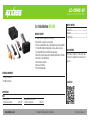
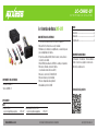
INTERFACE COMPONENTS
TOOLS REQUIRED
• Wire cutter • Crimp tool • Solder gun • Tape
• Connectors (example: butt-connectors, bell
caps, etc.)
TABLE OF CONTENTS
Connections ............................................................2
Installation .............................................................3
Programming .........................................................3
Ram Data Interface 2013-2017
• Provides accessory power (12-volt 10-amp)
• Retains R.A.P. (retained accessory power)
• Used in non-amplified models, or when bypassing a factory amplifier
• Provides NAV outputs (parking brake, reverse, and speed sense)
• Pre-wired ASWC-1 harness (ASWC-1 sold separately)
•
Retains the factory backup camera (if displayed through the OE radio)
• Retains the 3.5mm AUX-IN jack
• Retains balance and fade
• Retains safety chimes
• Micro-B USB updatable
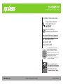
• LC-CHRC-01 interface
• LC-CHRC-01 harness
APPLICATIONS
RAM
1500/2500/3500
(small screen option) 2013-2017
Chassis Cab 3500/4500/5500
(small screen option) 2013-2017

2
CONNECTIONS
From the LC-CHRC-01 harness to the aftermarket radio:
• Connect the Black wire to the ground wire.
• Connect the Yellow wire to the battery wire.
• Connect the Red wire to the accessory wire.
• If the aftermarket radio has an illumination wire, connect the Orange wire to it.
• Connect the Gray wire to the right front positive speaker output.
• Connect the Gray/Black wire to the right front negative speaker output.
• Connect the White wire to the left front positive speaker output.
• Connect the White/Black wire to the left front negative speaker output.
• Connect the Green wire to the left rear positive speaker output.
• Connect the Green/Black wire to the left rear negative speaker output.
• Connect the Purple wire to the right rear positive speaker output.
• Connect the Purple/Black wire to the right rear negative speaker output.
The following (3) wires are only for multimedia/navigation radios that require these wires.
• Connect the Blue/Pink wire to the VSS/speed sense wire.
• Connect the Green/Purple wire to the reverse wire.
• Connect the Light Green wire to the parking brake wire.
• Connect the Yellow RCA jack the backup camera input.
• If retaining the factory AUX-IN jack, connect the Red & White RCA jacks to the AUX input.
• Tape off and disregard the Blue/White wire, it will not be used in this application.
12-pin pre-wired ASWC-1 harness:
• This harness is to be used along with the optional ASWC-1 (not included) to retain steering
wheel audio controls. If the ASWC-1 is not being used, disregard this harness. If it will be
used, please refer to the ASWC-1 instructions for radio connections and programming.
Note: Disregard the harness that comes with the ASWC-1.
• Connect the Red wire to the accessory wire.

3
REV. 9/30/2019 INSTLC-CHRC-01
INSTALLATION PROGRAMMING
With the key in the off position:
• Connect the LC-CHRC-01 harness into the interface, and then to the harness in the vehicle.
Note: If using the ASWC-1, connect it after you initialize and test the LC-CHRC-01, with the key
in the off position.
Attention!
If the interface loses power for any reason, the following steps will need to be
performed again. Also, if installing an ASWC-1 connect it after you initialize and test the interface/
radio, with the key in the off position.
• Turn the key (or push-to-start button) to the ignition position and wait until the radio comes on
.
Note: If the radio does not come on within 60 seconds, turn the key to the off position,
disconnect the interface, check all connections, reconnect the interface, and then try again.
• Turn the key to the off position, and then to the accessory position. Test all functions of the
installation for proper operation, before reassembling the dash.

INSTALLATION INSTRUCTIONS
LC-CHRC-01
KNOWLEDGE IS POWER
Enhance your installation and fabrication skills by
enrolling in the most recognized and respected
mobile electronics school in our industry.
Log onto www.installerinstitute.com or call
800-354-6782 for more information and take steps
toward a better tomorrow.
®
Metra recommends MECP
certified technicians
AxxessInterfaces.com © COPYRIGHT 2019 METRA ELECTRONICS CORPORATION REV. 9/30/19 INSTLC-CHRC-01
Having difficulties? We’re here to help.
Contact our Tech Support line at:
386-257-1187
Or via email at:
techsupport@metra-autosound.com
Tech Support Hours (Eastern Standard Time)
Monday - Friday: 9:00 AM - 7:00 PM
Saturday: 10:00 AM - 7:00 PM
Sunday: 10:00 AM - 4:00 PM

LC-CHRC-01
INSTRUCCIONES DE INSTALACIÓN
AxxessInterfaces.com © COPYRIGHT 2019 METRA ELECTRONICS CORPORATION REV. 9/30/19 INSTLC-CHRC-01
Información del producto
CARACTERÍSTICAS DE LA INTERFASE
COMPONENTES DE LA INTERFASE
HERRAMIENTAS REQUERIDAS
• Cortacables • Ponchadora • Pistola soldadora
• Cinta • Conectores (ejemplo: conectores de
extremo, de campana, etc.)
INDICE
Conexiones .............................................................2
Instalación ..............................................................3
Programación .........................................................3
Ram Interfase de Datos 2013-2017
• Provee corriente de accesorios (12 voltios 10 amperes)
• Retiene R.A.P. (corriente de accesorio retenida)
• Utilizados en los modelos no amplificados, o cuando sin pasar
por un amplificador de fábrica
• Proporciona salidas de NAV (freno de mano, reversa, silencio
y sensor de velocidad)
• Arnés ASWC-1 precableado (el ASWC-1 se vende por separado)
• Retiene la cámara de reversa de fábrica
(si se visualiza a través de la radio OE)
• Retiene el conector de 3.5mm AUX-IN
• Retiene el balance y la intensidad
• Retiene campanadas de seguridad
• Actualizable por micro-B USB
• Interfaz LC-CHRC-01
• Arnés LC-CHRC-01
APLICACIONES
RAM
1500/2500/3500
(opción de pantalla pequeña) 2013-2017
Chassis Cab 3500/4500/5500
(opción de pantalla pequeña) 2013-2017

2
CONEXIONES
Desde el arnés LC-CHRC-01 al radio de mercado secundario:
• Conecte el cable negro al cable de tierra.
• Conecte el cable amarillo al cable de la batería.
• Conecte el cable rojo con el cable de accesorios.
• Si el radio de mercado secundario tiene un cable de iluminación, conecte el cable
anaranjado a ella.
• Conecte el cable gris con la salida positiva de la bocina derecha delantera.
• Conecte el cable gris/negro con la salida negativa de la bocina derecha delantera.
• Conecte el cable blanco con la salida positiva de la bocina izquierda delantera.
• Conecte el cable blanco/negro con la salida negativa de la bocina izquierda delantera.
• Conecte el cable verde con la salida positiva de la bocina izquierda trasera.
• Conecte el cable verde/negro con la salida negativa de la bocina izquierda trasera.
• Conecte el cable púrpura con la salida positiva de la bocina derecha trasera.
• Conecte el cable púrpura/negro con la salida negativa de la bocina derecha trasera.
Los siguientes (3) cables son para radios de mercado secundario con multimedios/navegación
que tienen estos cables.
• Conecte el cable azul/rosa al cable VSS o de detección de velocidad.
• Conecte el cable verde/púrpura al cable de reversa.
• Conecte el cable verde claro al cable de freno de mano.
• Conecte el conector RCA amarillo a la entrada de la cámara de reversa.
• Si retener el enchufe AUX-IN de fábrica, conecte los conectores RCA rojo y blanco al entrada AUX.
• Encinte e ignore el cable azul/blanco, no se utilizará en esta aplicación.
Arnés ASWC-1 precableado de 12 pins
• Este arnés se debe usar junto con el ASWC-1 opcional (no incluido) para retener los controles
de audio en el volante. Si no se usará el ASWC-1, ignore este arnés. Si se va a utilizar,
consulte las instrucciones de ASWC-1 para las conexiones del radio y la programación.
Nota: Ignore el arnés que viene con el ASWC-1.
• Conecte el cable rojo con el cable de accesorios.

3
REV. 9/30/2019 INSTLC-CHRC-01
INSTAL ACIÓN PROGRAMACIÓN
Con la llave en la posición de apagado:
• Conecte el arnés LC-CHRC-01 a la interfase, y luego al arnés en el vehículo.
Nota: Si va a utilizar el ASWC-1, conéctelo después de inicializar y probar el
LC-CHRC-01 con la llave en la posición de apagado.
Atención!
Si la interfase pierde energía por cualquier razón, tendrán que volverse a ejecutar los
siguientes pasos. Si va a utilizar el ASWC-1, conéctelo después de inicializar y probar el interfase/
radio con la llave en la posición de apagado.
• Gire la llave (o pulsar para botón de inicio) a la posición de encendido and y esperar hasta
que la radio se enciende.
Nota: Si la radio no se enciende dentro de 60 segundos, gire la llave a la posición de
apagado, desconecte la interfase, compruebe todas las conexiones, vuelva a conectar la
interfase, y vuelva a intentarlo.
•
Gire la llave a la posición de apagado, y luego a la posición de accesorios. Pruebe todas las
funciones de la instalación para su correcto funcionamiento, antes de volver a montar el tablero.

INSTRUCCIONES DE INSTALACIÓN
LC-CHRC-01
AxxessInterfaces.com © COPYRIGHT 2019 METRA ELECTRONICS CORPORATION REV. 9/30/19 INSTLC-CHRC-01
¿Tienes dificultades? Estamos aquí para ayudar.
Póngase en contacto con nuestra
línea de soporte técnico en:
386-257-1187
O por correo electrónico a:
techsupport@metra-autosound.com
Horario de Soporte Técnico (hora estándar del este)
Lunes - Viernes: 9:00 AM - 7:00 PM
Sábado: 10:00 AM - 7:00 PM
Domingo: 10:00 AM - 4:00 PM
KNOWLEDGE IS POWER
Enhance your installation and fabrication skills by
enrolling in the most recognized and respected
mobile electronics school in our industry.
Log onto www.installerinstitute.com or call
800-354-6782 for more information and take steps
toward a better tomorrow.
®
Metra recomienda técnicos
con certificación del Programa
de Certificación en Electrónica
Móvil (Mobile Electronics
Certification Program, MECP).
EL CONOCIMIENTO ES PODER
Mejore sus habilidades de instalación y
fabricación inscribiéndose en la escuela de
dispositivos electrónicos móviles más reconocida
y respetada de nuestra industria. Regístrese en
www.installerinstitute.com o llame al
800-354-6782 para obtener más información y
avance hacia un futuro mejor.
-
 1
1
-
 2
2
-
 3
3
-
 4
4
-
 5
5
-
 6
6
-
 7
7
-
 8
8


en otros idiomas
- English: Axxess LC-CHRC-01 Installation guide
Artículos relacionados
-
Axxess GMOS-MOST-01 Installation Instructions Manual
-
-
-
Axxess GMOS-MOST-02 Installation Instructions Manual
-
-
-
-
-
-