Yamaha RX-V461 Manual de usuario
- Categoría
- Receptores AV
- Tipo
- Manual de usuario
Este manual también es adecuado para

YAMAHA ELECTRONICS CORPORATION, USA
6660 ORANGETHORPE AVE., BUENA PARK, CALIF. 90620, U.S.A.
YAMAHA CANADA MUSIC LTD.
135 MILNER AVE., SCARBOROUGH, ONTARIO M1S 3R1, CANADA
YAMAHA ELECTRONIK EUROPA G.m.b.H.
SIEMENSSTR. 22-34, 25462 RELLINGEN BEI HAMBURG, GERMANY
YAMAHA ELECTRONIQUE FRANCE S.A.
RUE AMBROISE CROIZAT BP70 CROISSY-BEAUBOURG 77312 MARNE-LA-VALLEE CEDEX02, FRANCE
YAMAHA ELECTRONICS (UK) LTD.
YAMAHA HOUSE, 200 RICKMANSWORTH ROAD WATFORD, HERTS WD18 7GQ, ENGLAND
YAMAHA SCANDINAVIA A.B.
J A WETTERGRENS GATA 1, BOX 30053, 400 43 VÄSTRA FRÖLUNDA, SWEDEN
YAMAHA MUSIC AUSTRALIA PTY, LTD.
17-33 MARKET ST., SOUTH MELBOURNE, 3205 VIC., AUSTRALIA
©
2007 All rights reserved.
Printed in China WJ63930
RX-V461
AV Receiver
OWNER’S MANUAL
U
RX-V461_U-cv.fm Page 1 Thursday, December 14, 2006 1:24 PM

IMPORTANT SAFETY INSTRUCTIONS
Caution-i En
• Explanation of Graphical Symbols
The lightning flash with arrowhead symbol, within an
equilateral triangle, is intended to alert you to the
presence of uninsulated “dangerous voltage” within
the product’s enclosure that may be of sufficient
magnitude to constitute a risk of electric shock to
persons.
The exclamation point within an equilateral triangle
is intended to alert you to the presence of important
operating and maintenance (servicing) instructions in
the literature accompanying the appliance.
1 Read Instructions – All the safety and operating instructions
should be read before the product is operated.
2 Retain Instructions – The safety and operating instructions
should be retained for future reference.
3 Heed Warnings – All warnings on the product and in the
operating instructions should be adhered to.
4 Follow Instructions – All operating and use instructions
should be followed.
5 Cleaning – Unplug this product from the wall outlet before
cleaning. Do not use liquid cleaners or aerosol cleaners.
6 Attachments – Do not use attachments not recommended by
the product manufacturer as they may cause hazards.
7 Water and Moisture – Do not use this product near water –
for example, near a bath tub, wash bowl, kitchen sink, or
laundry tub; in a wet basement; or near a swimming pool;
and the like.
8 Accessories – Do not place this product on an unstable cart,
stand, tripod, bracket, or table. The product may fall,
causing serious injury to a child or adult, and serious
damage to the product. Use only with a cart, stand, tripod,
bracket, or table recommended by the manufacturer, or sold
with the product. Any mounting of the product should
follow the manufacturer’s instructions, and should use a
mounting accessory recommended by the manufacturer.
9 A product and cart combination should be moved with care.
Quick stops, excessive force, and uneven surfaces may
cause the product and cart combination to
overturn.
10 Ventilation – Slots and openings in the cabinet are provided
for ventilation and to ensure reliable operation of the
product and to protect it from overheating, and these
openings must not be blocked or covered. The openings
should never be blocked by placing the product on a bed,
sofa, rug, or other similar surface. This product should not
be placed in a built-in installation such as a bookcase or rack
unless proper ventilation is provided or the manufacturer’s
instructions have been adhered to.
11 Power Sources – This product should be operated only from
the type of power source indicated on the marking label. If
you are not sure of the type of power supply to your home,
consult your product dealer or local power company. For
products intended to operate from battery power, or other
sources, refer to the operating instructions.
12 Grounding or Polarization – This product may be equipped
with a polarized alternating current line plug (a plug having
one blade wider than the other). This plug will fit into the
power outlet only one way. This is a safety feature. If you
are unable to insert the plug fully into the outlet, try
reversing the plug. If the plug should still fail to fit, contact
your electrician to replace your obsolete outlet. Do not
defeat the safety purpose of the polarized plug.
13 Power-Cord Protection – Power-supply cords should be
routed so that they are not likely to be walked on or pinched
by items placed upon or against them, paying particular
attention to cords at plugs, convenience receptacles, and the
point where they exit from the product.
14 Lightning – For added protection for this product during a
lightning storm, or when it is left unattended and unused for
long periods of time, unplug it from the wall outlet and
disconnect the antenna or cable system. This will prevent
damage to the product due to lightning and power-line
surges.
15 Power Lines – An outside antenna system should not be
located in the vicinity of overhead power lines or other
electric light or power circuits, or where it can fall into such
power lines or circuits. When installing an outside antenna
system, extreme care should be taken to keep from touching
such power lines or circuits as contact with them might be
fatal.
16 Overloading – Do not overload wall outlets, extension
cords, or integral convenience receptacles as this can result
in a risk of fire or electric shock.
17 Object and Liquid Entry – Never push objects of any kind
into this product through openings as they may touch
dangerous voltage points or short-out parts that could result
in a fire or electric shock. Never spill liquid of any kind on
the product.
18 Servicing – Do not attempt to service this product yourself
as opening or removing covers may expose you to
dangerous voltage or other hazards. Refer all servicing to
qualified service personnel.
19 Damage Requiring Service – Unplug this product from the
wall outlet and refer servicing to qualified service personnel
under the following conditions:
a) When the power-supply cord or plug is damaged,
b) If liquid has been spilled, or objects have fallen into the
product,
c) If the product has been exposed to rain or water,
Important safety instructions
CAUTION
CAUTION: TO REDUCE THE RISK OF
ELECTRIC SHOCK, DO NOT REMOVE
COVER (OR BACK). NO USER-SERVICEABLE
PARTS INSIDE. REFER SERVICING TO
QUALIFIED SERVICE PERSONNEL.
RISK OF ELECTRIC SHOCK
DO NOT OPEN

Important safety instructions
Caution-ii En
EXAMPLE OF ANTENNA GROUNDING
MAST
GROUND
CLAMP
ANTENNA
LEAD IN
WIRE
ANTENNA
DISCHARGE UNIT
(NEC SECTION 810–20)
GROUNDING CONDUCTORS
(NEC SECTION 810–21)
GROUND CLAMPS
POWER SERVICE GROUNDING
ELECTRODE SYSTEM
(NEC ART 250. PART H)
ELECTRIC
SERVICE
EQUIPMENT
NEC – NATIONAL ELECTRICAL CODE
d) If the product does not operate normally by following
the operating instructions. Adjust only those controls
that are covered by the operating instructions as an
improper adjustment of other controls may result in
damage and will often require extensive work by a
qualified technician to restore the product to its normal
operation,
e) If the product has been dropped or damaged in any
way, and
f) When the product exhibits a distinct change in perfor-
mance - this indicates a need for service.
20 Replacement Parts – When replacement parts are required,
be sure the service technician has used replacement parts
specified by the manufacturer or have the same
characteristics as the original part. Unauthorized
substitutions may result in fire, electric shock, or other
hazards.
21 Safety Check – Upon completion of any service or repairs to
this product, ask the service technician to perform safety
checks to determine that the product is in proper operating
condition.
22 Wall or Ceiling Mounting – The unit should be mounted
to a wall or ceiling only as recommended by the
manufacturer.
23 Heat – The product should be situated away from heat
sources such as radiators, heat registers, stoves, or other
products (including amplifiers) that produce heat.
24 Outdoor Antenna Grounding – If an outside antenna or
cable system is connected to the product, be sure the antenna
or cable system is grounded so as to provide some
protection against voltage surges and built-up static charges.
Article 810 of the National Electrical Code, ANSI/NFPA 70,
provides information with regard to proper grounding of the
mast and supporting structure, grounding of the lead-in wire
to an antenna discharge unit, size of grounding conductors,
location of antenna discharge unit, connection to grounding
electrodes, and requirements for the grounding electrode.
Note to CATV system installer:
This reminder is provided to call the CATV system installer’s
attention to Article 820-40 of the NEC that provides
guidelines for proper grounding and, in particular, specifies
that the cable ground shall be connected to the grounding
system of the building, as close to the point of cable entry as
practical.
FCC INFORMATION (for US customers)
1 IMPORTANT NOTICE: DO NOT MODIFY THIS
UNIT!
This product, when installed as indicated in the
instructions contained in this manual, meets FCC
requirements. Modifications not expressly approved by
Yamaha may void your authority, granted by the FCC, to
use the product.
2 IMPORTANT: When connecting this product to
accessories and/or another product use only high quality
shielded cables. Cable/s supplied with this product MUST
be used. Follow all installation instructions. Failure to
follow instructions could void your FCC authorization to
use this product in the USA.
3 NOTE: This product has been tested and found to comply
with the requirements listed in FCC Regulations, Part 15
for Class “B” digital devices. Compliance with these
requirements provides a reasonable level of assurance that
your use of this product in a residential environment will
not result in harmful interference with other electronic
devices.
This equipment generates/uses radio frequencies and, if
not installed and used according to the instructions found
in the users manual, may cause interference harmful to the
operation of other electronic devices.
Compliance with FCC regulations does not guarantee that
interference will not occur in all installations. If this
product is found to be the source of interference, which
can be determined by turning the unit “OFF” and “ON”,
please try to eliminate the problem by using one of the
following measures:
Relocate either this product or the device that is being
affected by the interference.
Utilize power outlets that are on different branch (circuit
breaker or fuse) circuits or install AC line filter/s.
In the case of radio or TV interference, relocate/reorient
the antenna. If the antenna lead-in is 300 ohm ribbon lead,
change the lead-in to coaxial type cable.
If these corrective measures do not produce satisfactory
results, please contact the local retailer authorized to
distribute this type of product. If you can not locate the
appropriate retailer, please contact Yamaha Electronics
Corp., U.S.A. 6660 Orangethorpe Ave., Buena Park, CA
90620.
The above statements apply ONLY to those products
distributed by Yamaha Corporation of America or its
subsidiaries.

CAUTION: READ THIS BEFORE OPERATING YOUR UNIT.
Caution-iii En
1 To assure the finest performance, please read this manual
carefully. Keep it in a safe place for future reference.
2 Install this sound system in a well ventilated, cool, dry, clean
place – away from direct sunlight, heat sources, vibration,
dust, moisture, and/or cold. Allow ventilation space of at least
30 cm on the top, 20 cm on the left and right, and 20 cm on
the back of this unit.
3 Locate this unit away from other electrical appliances, motors,
or transformers to avoid humming sounds.
4 Do not expose this unit to sudden temperature changes from
cold to hot, and do not locate this unit in a environment with
high humidity (i.e. a room with a humidifier) to prevent
condensation inside this unit, which may cause an electrical
shock, fire, damage to this unit, and/or personal injury.
5 Avoid installing this unit where foreign object may fall onto
this unit and/or this unit may be exposed to liquid dripping or
splashing. On the top of this unit, do not place:
– Other components, as they may cause damage and/or
discoloration on the surface of this unit.
– Burning objects (i.e. candles), as they may cause fire,
damage to this unit, and/or personal injury.
– Containers with liquid in them, as they may fall and liquid
may cause electrical shock to the user and/or damage to
this unit.
6 Do not cover this unit with a newspaper, tablecloth, curtain,
etc. in order not to obstruct heat radiation. If the temperature
inside this unit rises, it may cause fire, damage to this unit,
and/or personal injury.
7 Do not plug in this unit to a wall outlet until all connections
are complete.
8 Do not operate this unit upside-down. It may overheat,
possibly causing damage.
9 Do not use force on switches, knobs and/or cords.
10 When disconnecting the power cable from the wall outlet,
grasp the plug; do not pull the cord.
11 Do not clean this unit with chemical solvents; this might
damage the finish. Use a clean, dry cloth.
12 Only voltage specified on this unit must be used. Using this
unit with a higher voltage than specified is dangerous and may
cause fire, damage to this unit, and/or personal injury. Yamaha
will not be held responsible for any damage resulting from use
of this unit with a voltage other than specified.
13 To prevent damage by lightning, keep the power cord and
outdoor antennas disconnected from a wall outlet or the unit
during a lightning storm.
14 Do not attempt to modify or fix this unit. Contact qualified
Yamaha service personnel when any service is needed. The
cabinet should never be opened for any reasons.
15 When not planning to use this unit for long periods of time
(i.e. vacation), disconnect the AC power plug from the wall
outlet.
16 Install this unit near the AC outlet and where the AC power
plug can be reached easily.
17 Be sure to read the “Troubleshooting” section on common
operating errors before concluding that this unit is faulty.
18 Before moving this unit, press STANDBY/ON to set this unit
in the standby mode, and disconnect the AC power plug from
the wall outlet.
19 VOLTAGE SELECTOR (Asia and General models only)
The VOLTAGE SELECTOR on the rear panel of this unit
must be set for your local main voltage BEFORE plugging
into the AC wall outlet.
Voltages are 110–120/220–240 V AC, 50/60 Hz.
20 The batteries shall not be exposed to excessive heat such as
sunshine, fire or like.
Caution: Read this before operating your unit.
WARNING
TO REDUCE THE RISK OF FIRE OR ELECTRIC
SHOCK, DO NOT EXPOSE THIS UNIT TO RAIN
OR MOISTURE.
This unit is not disconnected from the AC power
source as long as it is connected to the wall outlet, even
if this unit itself is turned off by STANDBY/ON. This
state is called the standby mode. In this state, this unit
is designed to consume a very small quantity of power.
FOR CANADIAN CUSTOMERS
To prevent electric shock, match wide blade of plug to
wide slot and fully insert.
This Class B digital apparatus complies with Canadian
ICES-003.
POUR LES CONSOMMATEURS CANADIENS
Pour éviter les chocs électriques, introduire la lame la
plus large de la fiche dans la borne correspondante de
la prise et pousser jusqu’au fond.
Cet appareil numérique de la classe B est conforme à
la norme NMB-003 du Canada.
IMPORTANT
Please record the serial number of this unit in the space
below.
MODEL:
Serial No.:
The serial number is located on the rear of the unit.
Retain this Owner’s Manual in a safe place for future
reference.

1 En
English
PREPARATIONINTRODUCTION
BASIC
OPERATION
ADVANCED
OPERATION
ADDITIONAL
INFORMATION
APPENDIX
Features ................................................................... 2
Getting started ........................................................ 3
Quick start guide .................................................... 4
Preparation: Check the items ..................................... 4
Step 1: Set up your speakers ...................................... 5
Step 2: Connect your DVD player
and other components............................................ 6
Step 3: Turn on the power
and press SCENE 1 button .................................... 8
What do you want to do with this unit? ..................... 9
Connections ........................................................... 10
Rear panel ................................................................ 10
Placing speakers....................................................... 11
Connecting speakers ................................................ 12
Setting the speaker impedance
(U.S.A. and Canada models only) ....................... 13
Information on jacks and cable plugs ...................... 14
Connecting video components................................. 15
Connecting audio components................................. 17
Connecting a Yamaha iPod universal dock ............. 18
Using the VIDEO AUX jacks on the front panel .... 18
Connecting the FM and AM antennas ..................... 19
Connecting the power cable..................................... 19
Turning on and off the power .................................. 19
Front panel display .................................................. 20
Optimizing the speaker setting
for your listening room .................................... 22
Using AUTO SETUP .............................................. 22
Selecting the SCENE templates........................... 26
Selecting the desired SCENE template.................... 26
Creating your original SCENE templates................ 29
Playback ................................................................ 30
Basic operations....................................................... 30
Additional operations............................................... 31
Sound field programs ........................................... 35
Sound field program descriptions ............................ 35
FM/AM tuning ...................................................... 38
Automatic tuning ..................................................... 38
Manual tuning .......................................................... 38
Automatic preset tuning........................................... 39
Manual preset tuning ............................................... 39
Selecting preset stations........................................... 40
Exchanging preset station ........................................ 40
XM Satellite Radio tuning ................................... 41
Connecting the XM Mini-Tuner Dock .................... 41
Activating XM Satellite Radio ................................ 42
Basic XM Satellite Radio operations....................... 42
Setting XM Satellite Radio preset channels ............ 44
Displaying the XM Satellite Radio information...... 45
Using iPod™.......................................................... 46
Controlling iPod™................................................... 46
Recording .............................................................. 48
SET MENU ............................................................49
Using SET MENU ................................................... 50
1 SOUND MENU.................................................... 51
2 INPUT MENU...................................................... 55
3 OPTION MENU................................................... 57
Remote control features........................................59
Using remote control on the SCENE feature........... 59
Controlling this unit, a TV, or other components.... 60
Setting remote control codes ................................... 62
Resetting all remote control codes........................... 63
Advanced setup......................................................64
Troubleshooting.....................................................65
Glossary..................................................................72
Specifications .........................................................74
Index .......................................................................75
(at the end of this manual)
Front panel................................................................i
Remote control ....................................................... ii
List of remote control codes ................................. iii
3
Contents
INTRODUCTION
PREPARATION
BASIC OPERATION
ADVANCED OPERATION
ADDITIONAL INFORMATION
APPENDIX
About this manual
• y indicates a tip for your operation.
• Some operations can be performed by using either the
buttons on the front panel or the ones on the remote control.
In case the button names differ between the front panel and
the remote control, the button name on the remote control is
given in parentheses.
• This manual is printed prior to production. Design and
specifications are subject to change in part as a result of
improvements, etc. In case of differences between the
manual and product, the product has priority.
•“
9
SPEAKERS” or “
A
DVD” (example) indicates the
name of the parts on the front panel or the remote control.
Refer to the attached sheet or the top pages of this manual
for the information about each position of the parts.
•The symbol “☞ ” with page number(s) indicates the
corresponding reference page(s).

Features
2 En
Built-in 5-channel power amplifier
◆ Minimum RMS output power
[U.S.A. and Canada models]
(1 kHz, 0.9% THD, 8 Ω)
Front: 100 W + 100 W
Center: 100 W
Surround: 100 W + 100 W
[Other models]
(1 kHz, 0.9% THD, 6 Ω)
Front: 100 W + 100 W
Center: 100 W
Surround: 100 W + 100 W
SCENE select function
◆ Preset SCENE templates for various situations
◆ SCENE template customizing capability
Decoders and DSP circuits
◆ Proprietary Yamaha technology for the creation of multi-
channel surround sound
◆ Compressed Music Enhancer mode to improve the sound
quality of compression artifacts (such as the MP3 format) to
that of a high-quality stereo
◆ Dolby Digital decoder
◆ Dolby Pro Logic/Dolby Pro Logic II decoder
◆ DTS decoder
◆ Neural Surround decoder
(U.S.A. and Canada models only)
◆ Virtual CINEMA DSP
◆ SILENT CINEMA
™
Sophisticated FM/AM tuner
◆ 40-station random and direct preset tuning
◆ Automatic preset tuning
XM Satellite Radio
(U.S.A. and Canada models only)
◆ XM Satellite Radio tuning capability (using the “XM Mini-
Tuner Dock” sold separately)
◆ Neural Surround decoder to play back the XM HD content of
XM Satellite Radio broadcasts in multi-channels, resulting in
a full surround sound experience
iPod controlling capability
◆ DOCK terminal to connect a Yamaha iPod universal dock
(YDS-10, sold separately), which supports iPod (Click and
Wheel), iPod nano, and iPod mini
◆ Playback information displaying capability
◆ Battery charging capability
Other features
◆ YPAO (Yamaha Parametric Room Acoustic Optimizer) for
automatic speaker setup
◆ 192-kHz/24-bit D/A converter
◆ Direct Stereo mode for pure hi-fi stereo sound for analog and
PCM 2-channel sources
◆ 6 additional input jacks for discrete multi-channel input
◆ OSD (on-screen display) menus that allow you to optimize
this unit to suit your individual audiovisual system
◆ Component video input/output capability
(3 COMPONENT VIDEO INs and 1 MONITOR OUT)
◆ S-video signal input/output capability
◆ Optical and coaxial digital audio signal jacks
◆ Sleep timer
◆ Cinema and music night listening modes
◆ Remote control with preset remote control codes
Manufactured under license from Dolby Laboratories.
“Dolby”, “Pro Logic”, and the double-D symbol are trademarks
of Dolby Laboratories.
“SILENT CINEMA” is a trademark of YAMAHA
CORPORATION.
“iPod” is a trademark of Apple Computer, Inc., registered in the
U.S. and other countries.
“DTS” and “DTS Digital Surround” are registered trademarks of
DTS, Inc.
The XM name and related logos are registered trademarks of XM
Satellite Radio Inc.
Neural Surround
™
name and related logos are trademarks owned
by Neural Audio Corporation.
We Want You Listening For A Lifetime
YAMAHA and the Electronic Industries Association’s Consumer
Electronics Group want you to get the most out of your
equipment by playing it at a safe level. One that lets the sound
come through loud and clear without annoying blaring or
distortion – and, most importantly, without affecting your
sensitive hearing.
Since hearing damage from loud sounds is often
undetectable until it is too late, YA M A H A and the
Electronic Industries Association’s Consumer
Electronics Group recommend you to avoid
prolonged exposure from excessive volume levels.
Features
iPod
TM

Getting started
3 En
English
INTRODUCTION
■ Checking the supplied accessories
Check that you received all of the following parts.
The form of the supplied accessories varies depending on the
models.
■ VOLTAGE SELECTOR
(Asia and General models only)
Select the switch position (upper or lower)
according to your local voltage using a straight
slot screwdriver.
Voltages are 110-120/220-240 V AC, 50/60 Hz.
■ Installing batteries in the remote control
1 Take off the battery compartment cover.
2 Insert the two supplied batteries
(AA, R6, UM-3) according to the polarity
markings (+ and –) on the inside of the
battery compartment.
3 Snap the battery compartment cover back
into place.
• Change all of the batteries if you notice the following
conditions:
– the operation range of the remote control decreases.
– the TRANSMIT indicator does not flash or its light becomes
dim.
• Do not use an old battery and a new one together.
• Do not use different types of batteries (such as alkaline and
manganese batteries) together. Read the packaging carefully as
these different types of batteries may have the same shape and
color.
• If the batteries have leaked, dispose of them immediately. Avoid
touching the leaked material or letting it come into contact with
clothing, etc. Clean the battery compartment thoroughly before
installing new batteries.
• Do not throw away batteries with general house waste; dispose
of them correctly in accordance with your local regulations.
• If the remote control is without batteries for more than 2
minutes, or if exhausted batteries remain in the remote control,
the contents of the memory may be cleared. When the memory
is cleared, insert new batteries and set up the remote control
code.
Getting started
Note
Caution
The VOLTAGE SELECTOR on the rear panel of this
unit must be set for your local voltage BEFORE
plugging the power cable into the AC wall outlet.
Improper setting of the VOLTAGE SELECTOR may
cause damage to this unit and create a potential fire
hazard.
5678
90
+10
ENT
1234
MENU
TITLE
SET MENU
LEVEL
MUSIC
MOVIEENTERTAIN STEREO
ENHANCER
STRAIGHT
DIRECT ST.
SUR. DECODE
NIGHT
SLEEP
DISPLAY
RETURN
BAND
SRCH MODE
XM MEMORY
REC
SCENE
A-E/CAT.
ENTER
PRESET/CH
VOLUME
TV VOL
TV CH
TV MUTE
TV INPUT
MUTE
AMP
SOURCE
TV
CD
CD-R
DVD
DTV
MD
MULTI CH IN
AUDIO SEL
CBL
TUNER
V-AUX
DOCK
DVR
XM
STANDBY
POWER
POWER
POWER
AV
TV
TRANSMIT
CODE SET
1
2 34
Remote control
Batteries (2)
(AA, R06, UM-3)
Indoor FM antenna
AM loop antenna
Optimizer
microphone
110V-
120V
220V-
240V
VOLTAGE
SELECTOR
Notes
1
3
2

Quick start guide
4 En
The following steps describe the easiest way to enjoy
DVD movie playback in your home theater.
In these steps, you need the following supplied
accessories.
❏ Indoor FM antenna
❏ AM loop antenna
The following items are not included in the package of this
unit.
❏ Speakers
❏ Front speakers ...................................... 2
❏ Center speaker ...................................... 1
❏ Surround speakers ............................... 2
Select magnetically shielded speakers. The
minimum required speakers are two front speakers.
❏ Active subwoofer ...................................... 1
Select an active subwoofer equipped with an RCA
input jack.
❏ Speaker cables .......................................... 5
❏ Subwoofer cable ........................................ 1
Select a monaural RCA cable.
❏ DVD player ................................................. 1
Select DVD player equipped with coaxial digital
audio output jack and composite video output
jack.
❏ Video monitor ............................................. 1
Select a TV monitor, video monitor or projector
equipped with a composite video input jack.
❏ Video cable ................................................ 1
Select an RCA composite video cable.
❏ Digital coaxial audio cable ....................... 1
Quick start guide
Front right
speaker
Subwoofer
Surround left
speaker
Front left
speaker
Surround right
speaker
Center speaker
DVD player
Video monitor
Enjoy DVD playback!
Step 1: Set up your speakers
Step 2: Connect your DVD player
and other components
Step 3: Turn on the power and
press SCENE 1 button
☞
P. 6
☞
P. 8
☞
P. 5
Preparation: Check the items

Quick start guide
5 En
English
INTRODUCTION
Place your speakers in the room and connect them to this
unit.
1 Place your speakers and subwoofer in the
room.
2 Connect speaker cables to each speaker.
Cables are colored or shaped differently, perhaps with
a stripe, groove or ridge. Connect the striped
(grooved, etc.) cable to the “+” (red) terminals of
your speaker. Connect the plain cable to the “–”
(black) terminals.
3 Connect each speaker cable to the
corresponding speaker terminal of this unit.
1 Make sure that this unit and the subwoofer are
unplugged from the AC wall outlets.
2 Twist the exposed wires of the speaker cables
together to prevent short circuits.
3 Do not let the bare speaker wires touch each other.
4 Do not let the bare speaker wires touch any metal
part of this unit.
Be sure to connect the left channel (L), right channel
(R), “+” (red) and “–” (black) properly.
Front speakers
Center and surround speakers
4 Connect the subwoofer cable to the input
jack of the subwoofer and the SUBWOOFER
OUTPUT jack of this unit.
Step 1: Set up your speakers
MULTI CH INPUT
COMPONENT VIDEO
DOCK
DIGITAL INPUT
XM
VIDEO
ANTENNA
SPEAKERS AC OUTLETS
LR LR
SURROUND CENTER FRONT B
AUDIO OUTPUT
L
1
2
3
R
L
R
L
R
DVD
DTV/CBL
D
V
R
CD
SUB
WO
O
FER
IN
OU
T
CENTER
SUBWOOFER
SURROUNDFRONT
DVD
OPTICAL
COAXIAL
CD
DTV/
CBL
DVD
P
R
P
B
Y
DTV/CBL DVR DVD
S VIDEO
VIDEO
DVR
AM
FRONT A
GND
FM
UNBAL.
75
IN OUT
DTV/CBLMONITOR
OUT
MONITOR
OUT
MD/
CD-R
OU
T
(
REC)
IN
(PLAY)
12 3 4
To the front
right speaker
Front left speaker
Loosen Insert Tighten
To the
surround
right speaker
To the surround
left speaker
To the center
speaker
OUTPUT
SUB
WOOFER
IN
(PLAY)
OUT
(REC)
MD/
CD-R
SUBWOOFER
OUTPUT jack
Subwoofer cable
Input jack
AV receiver
Subwoofer

Quick start guide
6 En
1 Connect the digital coaxial audio cable to the
digital coaxial audio output jack of your DVD
player and the DVD DIGITAL INPUT COAXIAL
jack of this unit.
2 Connect the video cable to the composite
video output jack of your DVD player and the
DVD VIDEO jack of this unit.
3 Connect the video cable to the video input
jack of your video monitor and the VIDEO
MONITOR OUT jack of this unit.
Step 2: Connect your DVD player
and other components
MULTI CH INPUT
COMPONENT VIDEO
DOCK
DIGITAL INPUT
XM
VIDEO
ANTENNA
SPEAKERS AC OUTLETS
LR LR
SURROUND CENTER FRONT B
AUDIO OUTPUT
L
1
2
3
R
L
R
L
R
DVD
DTV/CBL
D
V
R
CD
SUB
WO
O
FER
IN
OU
T
CENTER
SUBWOOFER
SURROUNDFRONT
DVD
OPTICAL
COAXIAL
CD
DTV/
CBL
DVD
P
R
P
B
Y
DTV/CBL DVR DVD
S VIDEO
VIDEO
DVR
AM
FRONT A
GND
FM
UNBAL.
75
IN OUT
DTV/CBLMONITOR
OUT
MONITOR
OUT
MD/
CD-R
OU
T
(REC)
IN
(PLAY)
Make sure that this unit and the DVD
player are unplugged from the AC wall
outlets.
Digital coaxial
audio output jack
Digital coaxial audio
cable
DVD DIGITAL INPUT
COAXIAL jack
DVD player
AV receiver
Composite video
output jack
Video cable
DVD VIDEO jack
DVD player
AV receiver
L/MONO
AUDIO AUDIO
COLOR STREAM HD
VIDEO
VIDEO-1 IN IN
S-VIDEO
RYP
B
P
R
RL/MONO
Video monitor
AV receiver
Video input jack
VIDEO MONITOR OUT
jack
Video cable

Quick start guide
7 En
English
INTRODUCTION
4 Connect the FM and AM antennas to this
unit.
See page 19 for the details.
y
The wire of the AM loop antenna does not have any polarity and
you can connect either end of the wire to AM and GND terminal.
5 Connect the power plug of this unit and other
components into the AC wall outlet.
y
This unit is equipped with AC OUTLET(S) for the power supply
of the other components (except Korea model). See page 19 for
details
Indoor FM antenna
AM loop antenna
Open the lever Insert Close the lever
■ For further connections
• Using the other kind of speaker
combinations
☞ P. 12
• Connecting a video monitor
☞ P. 15, 16
• Connecting a DVD player
☞ P. 15, 16
• Connecting a DVD recorder
☞ P. 15, 16
• Connecting a cable TV or a satellite tuner
☞ P. 15, 16
• Connecting a CD player and an MD
recorder
☞ P. 17
• Connecting a DVD player via analog
multi-channel audio connection
☞ P. 17
• Connecting a Yamaha iPod universal dock
☞ P. 18
• Using the VIDEO AUX jacks on the front
panel
☞ P. 18
• Connecting an outdoor FM/AM antenna
☞ P. 19
• Connecting the XM Mini-Tuner Dock
☞ P. 41

Quick start guide
8 En
1 Turn on the video monitor connected to this
unit.
2 Press
1
STANDBY/ON on the front panel.
3 Press
F
SCENE 1.
“DVD Viewing” appears in the front panel display,
and this unit automatically optimize own status for
the DVD playback.
y
The indicator on the selected SCENE button lights up while
this unit is in the SCENE mode.
4 Start playback of the desired DVD on your
player.
5 Rotate
8
VOLUME to adjust the volume.
When you change the input source or sound field program, the
SCENE mode is deactivated, and the indicator on the selected
SCENE button turns off.
■ Using the other SCENE buttons
In the following cases, try pressing the corresponding
SCENE button to enjoy playback of the desired sources.
Case A: “I want to listen to a music disc from the
connected DVD player as the background
music for this room...”
Press
F
SCENE 2 (or
F
SCENE 2) to select “Disc
Listening”.
Case B: “I want to watch a TV program...”
Press
F
SCENE 3 (or
F
SCENE 3) to select “TV
Viewing”.
To use the “TV Viewing” template (Case B), you must
connect a cable TV or a satellite tuner to this unit in
advance. See page 15 for details.
Step 3: Turn on the power and
press SCENE 1 button
Check the type of the connected speakers.
If the speakers are 6 ohm speakers, set “SP IMP.” to
“6Ω MIN” before using this unit (see page 13).
Note
Note

Quick start guide
9 En
English
INTRODUCTION
Case C: “I want to listen to a music program from
the FM radio station...”
Press
F
SCENE 4 (or
F
SCENE 4) to select “Radio
Listening”.
• To use the “Radio Listening” template (Case C), you must
tune into the desired radio station in advance. See pages 38
to 40 for tuning information.
• To achieve the best possible reception, orient the
connected AM loop antenna, or adjust the position of the
end of the indoor FM antenna.
y
If you cannot find the desired situation, you can select and change
the assigned SCENE template for the SCENE buttons. See
page 26 for details.
■ After using this unit...
Press
1
STANDBY/ON on the front panel to set
this unit to the standby mode.
This unit is set to the standby mode. In the standby mode,
this unit consumes a small amount of power in order to
receive infrared signals from the remote control. To turn
on this unit from the standby mode, press
1
STANDBY/
ON (or GSTANDBY). See page 19 for details.
In the standby mode, this unit consumes a small amount of power
in order to receive infrared signals from the remote control.
Notes
Note
What do you want to do with this
unit?
■ Customizing the SCENE templates
• Using various SCENE templates
☞ P. 26
• Creating your original SCENE templates
☞ P. 29
■ Using various input sources
• Basic controls of this unit
☞ P. 30
• Enjoying FM/AM radio programs
☞ P. 38
• Enjoying XM Satellite Radio programs
☞ P. 41
• Using your iPod with this unit.
☞ P. 46
■ Using various sound features
• Using various sound field programs
☞ P. 35
• Using the pure direct mode for the high
fidelity sound
☞ P. 32
• Customizing the sound field programs
☞ P. 37
■ Adjusting the parameters of this unit
• Automatically optimizing the speaker
parameters for your listening room (AUTO
SETUP)
☞ P. 22
• Manually adjusting various parameters of
this unit
☞ P. 49
• Setting the remote control
☞ P. 59
• Adjusting the advanced parameters
☞ P. 64
■ Additional features
Automatically turning off this unit
☞ P. 34

Connections
10 En
1 DOCK terminal
See page 18 for connection information.
2 XM jack (U.S.A. and Canada models only)
See page 41 for connection information.
3 COMPONENT VIDEO jacks
See page 16 for connection information.
4 VIDEO jacks
See pages 15 and 16 for connection information.
5 ANTENNA terminals
See page 19 for connection information.
6 SPEAKERS terminals
See page 12 for connection information.
7 AC OUTLET(S)
See page 19 for connection information.
8 DIGITAL INPUT jacks
See pages 15 and 17 for connection information.
9 MULTI CH INPUT jacks
See page 17 for connection information.
0 AUDIO jacks
See pages 15 and 17 for connection information.
A SUBWOOFER OUTPUT jack
See page 12 for connection information.
B VOLTAGE SELECTOR
(Asia and General models only)
See page 3 for details.
Connections
Rear panel
MULTI CH INPUT
COMPONENT VIDEO
DOCK
DIGITAL INPUT
XM
VIDEO
ANTENNA
SPEAKERS AC OUTLETS
L
R
L
R
SURROUND CENTER FRONT B
AUDIO OUTPUT
L
1
2
3
R
L
R
L
R
DVD
DT
V
/CBL
D
V
R
C
D
SUB
W
OO
F
E
R
IN
O
UT
CENTER
SUBWOOFER
SURROUNDFRONT
DVD
OPTICAL
COAXIAL
CD
DTV/
CBL
DVD
P
R
P
B
Y
DTV/CBL DVR DVD
S VIDEO
VIDEO
DVR
AM
FRONT A
GND
FM
UNBAL.
75
IN OUT
DTV/CBLMONITOR
OUT
MONITOR
OUT
M
D/
CD-R
O
UT
(
R
E
C
)
IN
(PLAY)
2
8 9 0 A B
1 3 4 5 6 7
(U.S.A. model)

11 En
Connections
English
PREPARATION
The speaker layout below shows the speaker setting we recommend. You can use it to enjoy CINEMA DSP and multi-
channel audio sources.
Front left and right speakers (FL and FR)
The front speakers are used for the main source sound plus effect sounds. Place these speakers at an equal distance from the
ideal listening position. The distance of each speaker from each side of the video monitor should be the same.
Center speaker (C)
The center speaker is for the center channel sounds (dialog, vocals, etc.). If for some reason it is not practical to use a
center speaker, you can do without it. Best results, however, are obtained with the full system.
Surround left and right speakers (SL and SR)
The surround speakers are used for effect and surround sounds.
Subwoofer (SW)
The use of a subwoofer with a built-in amplifier, such as the Yamaha Active Servo Processing Subwoofer System, is
effective not only for reinforcing bass frequencies from any or all channels, but also for high fidelity sound reproduction
of the LFE (low-frequency effect) channel included in Dolby Digital and DTS sources. The position of the subwoofer is
not so critical, because low bass sounds are not highly directional. But it is better to place the subwoofer near the front
speakers. Turn it slightly toward the center of the room to reduce wall reflections.
Placing speakers
60˚
30˚
FL
FR
C
SL
SR
SR
80˚
SL
FR
FL
C
SL
SR
SW
1.8 m (6 ft)

12 En
Connections
Be sure to connect the left channel (L), right channel (R), “+” (red) and “–” (black) properly. If the connections are faulty,
this unit cannot reproduce the input sources accurately.
A speaker cord is actually a pair of insulated cables running side by side. Cables are colored or shaped differently, perhaps with a stripe,
groove or ridge. Connect the striped (grooved, etc.) cable to the “+” (red) terminals of this unit and your speaker. Connect the plain cable
to the “–” (black) terminals.
Connecting speakers
Caution
• Before connecting the speakers, make sure that this unit is turned off (see page 19).
• Do not let the bare speaker wires touch each other or let them touch any metal part of this unit. This could damage
this unit and/or the speakers.
• Use the magnetically shielded speakers. If this type of speaker still creates interference with the monitor, place the
speakers away from the monitor.
• If you are to use 6 ohm speakers, be sure to set “SP IMP.” to “6Ω MIN” before using this unit (see page 13).
Note
Subwoofer
Center speaker
MULTI CH INPUT
COMPONENT VIDEO
DOCK
DIGITAL INPUT
XM
VIDEO
ANTENNA
SPEAKERS AC OUTLETS
L
R
L
R
SURROUND CENTER FRONT B
AUDIO OUTPUT
L
1
2
3
R
L
R
L
R
DT
V
/CBL
D
VR
C
D
SUB
W
OOF
ER
IN
O
UT
CENTER
SUBWOOFER
SURROUNDFRONT
DVD
OPTICAL
COAXIAL
CD
DTV/
CBL
DVD
P
R
P
B
Y
DTV/CBL DVR DVD
DVD
S VIDEO
VIDEO
DVR
AM
FRONT A
GND
FM
UNBAL.
75
IN OUT
DTV/CBLMONITOR
OUT
MONITOR
OUT
M
D/
CD
-
R
O
UT
(
R
E
C
)
IN
(PLAY)
Subwoofer
Front speakers (A)
LeftRight
Center
speaker
Front speakers (B)
LeftRight
Surround speakers
LeftRight
(U.S.A. model)

13 En
Connections
English
PREPARATION
■ Before connecting to the SPEAKERS
terminal
A speaker cord is actually a pair of insulated cables
running side by side. Cables are colored or shaped
differently, perhaps with a stripe, groove or ridges.
Connect the striped (grooved, etc.) cable to the “+” (red)
terminals of this unit and your speaker. Connect the plain
cable to the “–” (black) terminals.
Remove approximately 10 mm (3/8”) of insulation
from the end of each speaker cable and then
twist the bare wires of the cable together to
prevent short circuits.
■ Connecting to the SPEAKERS terminals
1 Loosen the knob.
2 Insert the bare end of the speaker wire into
the hole on the terminal.
3 Tighten the knob to secure the wire.
Connecting the banana plug
(except Korea and Asia models)
The banana plug is a single-pole electrical connector
widely used to terminate speaker cables. First, tighten the
knob and then insert the banana plug connector into the
end of the corresponding terminal.
1 Make sure this unit is turned off.
See page 19 for details about turning on or off this
unit.
2 Press and hold
0
TONE CONTROL and
then press
1
STANDBY/ON to turn on this
unit.
This unit turns on, an the advanced setup menu
appears in the front panel display.
3 Press
A
PROGRAM l / h repeatedly to
select “SP IMP.”.
The following display appears in the front panel
display.
4 Press
B
STRAIGHT repeatedly to select “6Ω
MIN”.
The following display appears in the front panel
display.
5 Press
1
STANDBY/ON to confirm your
selection and set this unit to the standby
mode.
The setting you made is reflected next time you turn on this unit.
10 mm (3/8”)
1
2
3
Red: positive (+)
Black: negative (–)
Banana plug
Setting the speaker impedance
(U.S.A. and Canada models only)
Caution
If you are to use 6 ohm speakers, set “SP IMP.” to “6Ω
MIN” as follows BEFORE using this unit.
Note
SP IMP.- 8 MIN
SP IMP.- 6 MIN

14 En
Connections
■ Audio jacks
This unit has three types of audio jacks. Connection
depends on the availability of audio jacks on your other
components.
AUDIO jacks
For conventional analog audio signals transmitted via left
and right analog audio cables. Connect red plugs to the
right jacks and white plugs to the left jacks.
DIGITAL AUDIO COAXIAL jacks
For digital audio signals transmitted via coaxial digital
audio cables.
DIGITAL AUDIO OPTICAL jacks
For digital audio signals transmitted via optical digital
audio cables.
• You can use the digital jacks to input PCM, Dolby Digital and
DTS bitstreams. All digital input jacks are compatible with
digital signals with up to 96 kHz of sampling frequency.
• This unit handles digital and analog signals independently. Thus
audio signals input at the digital jacks are not output at the
analog AUDIO OUT (REC) jacks.
• Pull out the cap from the optical jack before you connect the
fiber optic cable. Do not discard the cap. When you are not
using the optical jack, be sure to put the cap back in place. This
cap protects the jack from dust.
■ Video jacks
This unit has three types of video jacks. Connection
depends on the availability of input jacks on your video
monitor.
VIDEO jacks
For conventional composite video signals transmitted via
composite video cables.
S VIDEO jacks
For S-video signals, separated into the luminance (Y) and
chrominance (C) video signals transmitted on separate
wires of S-video cables.
COMPONENT VIDEO jacks
For component signals, separated into the luminance (Y)
and chrominance (P
B, PR) video signals transmitted on
separate wires of component video cables.
The OSD signal is not output at the DVR OUT (REC) jacks.
Information on jacks and cable plugs
VIDEO S VIDEO
COMPONENT VIDEO
Y P
B
P
R
PB
Y
P
R
S
V
COAXIAL
DIGITAL AUDIO
AUDIO
OPTICAL
DIGITAL AUDIO
R
L
C
O
R
L
Left and right
analog audio
cable plugs
Optical
digital
audio cable
plug
Coaxial
digital audio
cable plug
Composite
video cable
plug
Component
video cable
plugs
Audio jacks and cable plugs Video jacks and cable plugs
(Red)(White) (Orange) (Yellow) (Green) (Blue) (Red)
S-video
cable plug
Notes
Note
PR
P
B
Y
P
R
P
B
Y
Video signal flow for MONITOR OUT
Output
(MONITOR OUT)
Input
COMPONENT
VIDEO
VIDEO
S VIDEO

15 En
Connections
English
PREPARATION
Connect the video components as follows.
y
You can also connect a video monitor, DVD player, digital TV,
and cable TV to this unit using the S VIDEO or COMPONENT
VIDEO connections (see page 16).
■ Connecting a video monitor and a DVD
player
■ Connecting a cable TV/satellite tuner
and a DVD recorder
Connecting video components
Make sure that this unit and other
components are unplugged from the
AC wall outlets.
MULTI CH INPUT
COMPONENT VIDEO
DOCK
DIGITAL INPUT
XM
VIDEO
AUDIO
L
1
2
3
R
L
R
DTV/CBL
D
V
R
CD
IN
OUT
CENTER
SUBWOOFER
SURROUNDFRONT
DVD
OPTICAL
COAXIAL
CD
DTV/
CBL
DVD
P
R
P
B
Y
DTV/CBL DVR DVD
DVD
S VIDEO
VIDEO
DVR
IN OUT
DTV/CBLMONITOR
OUT
MONITOR
OUT
C
L
R
VV
DVD player
Video monitor
Video in
Video out
Audio out
Audio out
indicates recommended connections
indicates alternative connections
MULTI CH INPUT
COMPONENT VIDEO
DOCK
DIGITAL INPUT
XM
VIDEO
AUDIO
L
1
3
R
L
R
DTV/CBL
D
V
R
CD
IN
OUT
CENTER
SUBWOOFER
SURROUNDFRONT
DVD
OPTICAL
COAXIAL
CD
DTV/
CBL
DVD
P
R
P
B
Y
DTV/CBL DVR DVD
DVD
S VIDEO
VIDEO
DVR
IN OUT
DTV/CBLMONITOR
OUT
MONITOR
OUT
2
L
R
L
R
L
R
VVV
O
Cable TV or
Satellite tuner
DVD recorder
Audio out
Video out
Audio out
Audio in
Audio out
Video in
Video out
indicates recommended connections
indicates alternative connections

16 En
Connections
■ Connecting to the COMPONENT VIDEO or S VIDEO jacks
You can enjoy high-quality pictures by connecting your video monitor and video source components to this unit using
COMPONENT VIDEO or S VIDEO connections.
Be sure to connect your video components in the same way you connect your video monitor to this unit. For example, if you connect
your video monitor to this unit using a COMPONENT VIDEO connection, connect your video components to this unit using the
COMPONENT VIDEO connection.
COMPONENT VIDEO connection S VIDEO connection
Note
MULTI CH INPUT
COMPONENT VIDEO
L
R
CENTER
SUBWOOFER
SURROUNDFRONT
DVD
P
R
P
B
Y
DTV/CBL DVR MONITOR
OUT
P
R
P
B
Y
P
R
P
B
Y
P
R
P
B
Y
P
R
P
B
Y
DVD player
Video monitor
Video out
Video out
Video out
Video in
Cable TV or
satellite tuner
DVD recorder
VIDEO
AUDIO
L
R
D
TV
/CB
L
D
VR
C
D
I
N
O
UT
DVD
DVD
S VIDEO
VIDEO
DVR
IN OUT
DTV/CBL MONITOR
OUT
S S
S
S S
DVD player
Video monitor
Video out
Video out
Video out
Video in
Cable TV or
satellite tuner
DVD recorder
Video in

17 En
Connections
English
PREPARATION
Connect the audio components as follows.
■ Connecting a CD player and a CD
recorder/MD recorder
When you connect your CD player via analog and digital
connection, priority is given to the signal input at the DIGITAL
INPUT jack.
■ Connecting to the MULTI CH INPUT jacks
This unit is equipped with 6 additional input jacks (FRONT L/R, SURROUND L/R, CENTER and SUBWOOFER) for
discrete multi-channel input from a multi-format player, external decoder or sound processor. Connect the output jacks
on your multi-format player or external decoder to the MULTI CH INPUT jacks. Be sure to match the left and right
output jacks to the left and right input jacks for the front and surround channels.
• When you select the component connected to the MULTI CH
INPUT jacks as the input source (see page 31), this unit
automatically turns off the digital sound field processor, and
you cannot select sound field programs.
• This unit does not redirect signals input at the MULTI CH
INPUT jacks to accommodate for missing speakers. We
recommend that you connect a 5.1-channel speaker system
before using this feature.
Connecting audio components
Note
Make sure that this unit and other
components are unplugged from the
AC wall outlets.
MULTI CH INPUT
DIGITAL INPUT
R
SURROU
N
AUDIO OUTPU
T
L
1
3
R
L
R
DTV/CBL
DVR
CD
SUB
WOOFER
IN
OUT
CENTER
SUBWOOFER
SURROUNDFRONT
OPTICAL
COAXIAL
CD
DTV/
CBL
DVD
P
B
Y
DVD
VIDEO
FM
UNBAL.
75
MD/
CD-R
OUT
(REC)
IN
(P
L
AY )
2
L
R
L
R
L
R
O
CD player CD recorder or
MD recorder
Audio outAudio out Audio inAudio out
indicates recommended connections
indicates alternative connections
MULTI CH INPUT
L
1
R
SUBWOOFER
COAXIAL
DTV/
CBL
DVD
2
CENTERSURROUNDFRONT
L
R
L
R
Multi-format player or
external decoder
Surround out
Center out
Subwoofer out
Front out
Notes

18 En
Connections
This unit is equipped with the DOCK terminal on the rear
panel that allows you to connect a Yamaha iPod universal
dock (YDS-10, sold separately) where you can station
your iPod and control playback of your iPod using the
supplied remote control. Connect a Yamaha iPod universal
dock (YDS-10, sold separately) to the DOCK terminal on
the rear panel of this unit using its dedicated cable. Once
the connection is complete, station your iPod in the
Yamaha iPod universal dock.
Use the VIDEO AUX jacks on the front panel to connect a
game console or a video camera to this unit.
• To reproduce the source signals input at these jacks, select
“V-AUX” as the input source.
• When audio signals are input at the AUDIO jacks, PORTABLE
jack and the DOCK terminal on the rear panel, the priority order
of the input signal is as follows:
1. DOCK
2. PORTABLE
3. AUDIO
Connecting a Yamaha iPod
universal dock
Make sure that this unit and other
components are unplugged from the
AC wall outlets.
MULTI CH INPUT
COMPONENT VIDEO
DOCK
DIGITAL INPUT
XM
L
1
2
3
R
CENTER
SUBWOOFER
SURROUNDFRONT
DVD
OPTICAL
COAXIAL
CD
DTV/
CBL
DVD
P
R
P
B
Y
DTV/CBL DVR MONITOR
OUT
Yamaha iPod universal dock
(YDS-10, sold separately)
(U.S.A. model)
Using the VIDEO AUX jacks on the
front panel
Caution
Be sure to turn down the volume of this unit and other
components before making connections.
Notes
SPEAKERS
PHONES
SILENT CINEMA
STANDBY
/ON
A/B/OFF
l
PRESET/TUNING/CH
h
CATEGORY
A/B/C/D/E
FM/AM
EDIT
SEARCH MODE
PRESET/TUNING
MEMORY
DISPLAY
TUNING AUTO/MAN'L
OPTIMIZER MIC
AUDIO S ELECT
DIRECT STEREOSTRAIGHT
EFFECT
TONE CONTROL
l INPUT hl PROGRAM h
VOLUME
SCENE
1234
VIDEO L AUDIO R PORTABLE
VIDEO AUX
VIDEO L AUDIO R PORTABLE
VIDEO AUX
V
L
R
Game console or
video camera
Audio
output
Video
output
Audio
output
3.5 mm stereo
mini plug
Portable audio
player

19 En
Connections
English
PREPARATION
Both FM and AM indoor antennas are supplied with this
unit. In general, these antennas should provide sufficient
signal strength. Connect each antenna correctly to the
designated terminals.
• The AM loop antenna should be placed away from this unit.
• A properly installed outdoor antenna provides clearer reception
than an indoor one. If you experience poor reception quality,
install an outdoor antenna. Consult the nearest authorized
Yama h a dealer or service center about outdoor antennas.
• The AM loop antenna should always be connected, even if an
outdoor AM antenna is connected to this unit.
Once all connections are complete, plug the power cable
into the AC wall outlet.
■ AC OUTLET(S) (SWITCHED)
Australia model ...................................................... 1 outlet
Korea model ............................................................... None
Other models ......................................................... 2 outlets
Use these outlet(s) to supply power to any connected
components. Connect the power cable of your other
components to these outlet(s). Power to these outlet(s) is
supplied when this unit is turned on. However, power to
these outlet(s) is cut off when this unit is set to the standby
mode. For information on the maximum power or the total
power consumption of the components that can be
connected to these outlet(s), see “Specifications” on
page 74.
■ Turning on this unit
Press
1
STANDBY/ON (or
H
POWER) to turn
on this unit.
y
When you turn on this unit, there will be a 4 to 5-second delay
before this unit can reproduce sound.
■ Set this unit to the standby mode
Press
1
STANDBY/ON (or
G
STANDBY) to set
this unit to the standby mode.
In the standby mode, this unit consumes a small amount of
power in order to receive infrared signals from the remote
control.
Connecting the FM and AM
antennas
Notes
ANTENNA
AM
GND
FM
UNBAL.
75
MD/
C
D
-R
IN
(P
LAY)
AM loop
antenna
(supplied)
Ground
For maximum safety and minimum
interference, connect the antenna GND
terminal to a good earth ground. A good
earth ground is a metal stake driven into
moist earth.
Indoor FM
antenna
(supplied)
Outdoor AM antenna
Use a 5 to 10 m (16 to 32 ft) of
vinyl-covered wire extended
outdoors from a window.
Connecting the power cable
Turning on and off the power
AC OUTLETS
(U.S.A. model)
Power cable

20 En
Connections
1 Decoder indicator
The respective indicator lights up when any of the
decoders of this unit functions.
2 ENHANCER indicator
Lights up when the Compressed Music Enhancer mode is
selected (see page 35).
3 VIRTUAL indicator
Lights up when Virtual CINEMA DSP is active (see
page 36).
4 SILENT CINEMA indicator
Lights up when headphones are connected and a sound
field program is selected (see page 36).
5 DOCK indicator
Lights up when you station your iPod in a Yamaha iPod
universal dock (YDS-10, sold separately) connected to the
DOCK terminal of this unit (see page 18) and you select
V-AUX as the input source.
6 Input source indicators
The corresponding cursor lights up to show the currently
selected input source.
7 YPAO indicator
Lights up when you run “AUTO SETUP” and when the
speaker settings set in “AUTO SETUP” are used without
any modifications (see page 22).
8 Tuner indicators
Lights up when this unit is in the FM, AM or XM Satellite
Radio tuning mode (see pages 38 and 41).
9 MUTE indicator
Flashes while the MUTE function is on (see page 34).
0 VOLUME level indicator
Indicates the current volume level.
A PCM indicator
Lights up when this unit is reproducing PCM (Pulse Code
Modulation) digital audio signals.
B Headphones indicator
Lights up when headphones are connected (see page 34).
C SP A B indicators
Light up according to the set of front speakers selected
(see page 30).
D NIGHT indicator
Lights up when you select a night listening mode (see
page 33).
E CINEMA DSP indicator
Lights up when you select a CINEMA DSP sound
field program (see page 35).
HiFi DSP indicator
Lights up when you select a HiFi DSP sound field
program (see page 35).
F Multi-information display
Shows the name of the current sound field program and
other information when adjusting or changing settings.
G SLEEP indicator
Lights up while the sleep timer is on (see page 34).
H Input channel and speaker indicators
LFE indicator
Lights up when the input signal contains the LFE
signal.
Input channel indicators
Indicate the channel components of the current digital
input signal.
Front panel display
DVR DVD CD
XM
V-AUX DTV/CBL
MD/CD-R
TUNER
q PL
q PL
ENHANCER
SILENT CINEMA
NIGHT
DOCK
AUTO
YPAO
PRESET
TUNED
MUTE
VOLUME
MEMORY
SLEEP
VIRTUAL
PCM
neural
A B
SP
mS
ft
dB
HiFi DSP
LFE
LCR
SL SR
q
DIGITAL
t
dB
STEREO
BA D GF
H
E
6
54 7 8 01 2 3 9
C
Input channel indicators
LFE
LCR
SL SR
LFE indicator

21 En
Connections
English
PREPARATION
■ Using the remote control
The remote control transmits a directional infrared ray.
Be sure to aim the remote control directly at the remote
control sensor on this unit during operation.
W
Infrared window
Outputs infrared control signals. Aim this window at the
component you want to operate.
V
TRANSMIT indicator
Flashes while the remote control is sending infrared
signals.
K
Operation mode selector
The function of some buttons depends on the operation
mode selector position.
AMP
Operates the amplifier function of this unit.
SOURCE
Operates the component selected with an input
selector button (see page 61).
TV
Operates the TV assigned to DTV/CBL (see page 60).
y
To set the remote control codes for other components, see
page 62.
• Do not spill water or other liquids on the remote control.
• Do not drop the remote control.
• Do not leave or store the remote control in the following types
of conditions:
– places of high humidity, such as near a bath
– places of high temperature, such as near a heater or stove
– places of extremely low temperatures
– dusty places
Notes
SPEAKERS
PHONES
SILENT CINEMA
STANDBY
/ON
A/B/OFF
l
PRESET/TUNING/CH
h
CATEGORY
A/B/C/D/E
FM/AM
EDIT
SEARCH MODE
PRESET/TUNING
MEMORY
DISPLAY
TUNING AUTO/MAN'L
OPTIMIZER MIC
AUDIO SELECT
DIRECT STEREOSTRAIGHT
EFFECT
TONE CONTRO L
l INPUT hl PROGRAM h
VOLUME
SCENE
1234
VIDEO L AUDIO R PORTABLE
VIDEO AUX
30º 30º
Approximately 6 m (20 ft)

Optimizing the speaker setting for your listening room
22 En
This unit employs the YPAO (Yamaha Parametric Room Acoustic Optimizer) technology which lets you avoid
troublesome listening-based speaker setup and achieves highly accurate sound adjustments automatically. The supplied
optimizer microphone collects and this unit analyzes the sound your speakers produce in your actual listening
environment.
• Be advised that it is normal for loud test tones to be output
during the “AUTO SETUP” procedure.
• To achieve the best results, make sure the room is as quiet as
possible while the “AUTO SETUP” procedure is in progress. If
there is too much ambient noise, the results may not be
satisfactory.
y
You can run “AUTO SETUP” using the system menu that appears
in the OSD or in the front panel display. This manual uses the
OSD illustrations to explain the “AUTO SETUP” procedure.
1 Make sure of the following check points
before starting the AUTO SETUP operations.
❏ Speakers are connected appropriately.
❏ Headphones are disconnected from this unit.
❏ This unit and the video monitor are turned on.
❏ The connected subwoofer is turned on and the
volume level is set to about half way (or slightly
less).
❏ The crossover frequency controls of the
connected subwoofer is set to the maximum.
❏ FRONT A speakers are selected as the front
speaker system (see page 30).
❏ The room is sufficiently quiet.
2 Connect the supplied optimizer microphone
to the OPTIMIZER MIC jack on the front
panel.
The following display appears in the OSD.
3 Place the optimizer microphone at your
normal listening position on a flat level
surface with the microphone heading
upward.
y
It is recommended that you use a tripod (etc.) to affix the
optimizer microphone at the same height as your ears would be
when you are seated in your listening position. You can use the
attached screw of a tripod (etc.) to fix the optimizer microphone
to the tripod (etc.).
Optimizing the speaker setting for your listening room
Using AUTO SETUP
Notes
Y
DISPLAY
TUNING AUTO/MAN'L
OPTIMIZER MIC
AUDIO SELECT
VIDEO L AUDIO R PORTABLE
VIDEO AUX
Optimizer
microphone
AUTO:MENU
. SETUP;;;;;;;AUTO
START
Automatic
Processing
of all item
[ ]/[ ]:Up/Down
[ ]/[ ]:Select
p
[
p
p
Optimizer microphone

23 En
Optimizing the speaker setting for your listening room
English
PREPARATION
4 Set the operation mode selector (K) to AMP
and then press
D
l / h to select “AUTO”.
Choices: AUTO, RELOAD, UNDO, DEFAULT
• Select “AUTO” to automatically run the entire
“AUTO SETUP” procedure.
• Select “RELOAD” to reload the last “AUTO
SETUP” settings and override the previous
settings.
• Select “UNDO” to undo the last “AUTO SETUP”
settings and restore the previous settings.
• Select “DEFAULT” to reset the “AUTO SETUP”
parameters to the initial factory settings.
“RELOAD” or “UNDO” is available only when you have
previously run “AUTO SETUP” and confirmed the results.
5 Press
D
n to select “START” and then press
D
ENTER to start the setup procedure.
This unit starts the auto setup procedure. Loud test
tones are output from each speaker during the auto
setup procedure. Once all items are set, the
“AUTO:RESULT” display appears in the OSD.
• During the auto setup procedure, do not perform any
operation on this unit.
• We recommend getting out of the room while this unit is in
the auto setup procedure. It takes approximately 3 minutes
for this unit to complete the auto setup procedure.
This unit performs the following checks:
Speaker wiring/volume level WIRING/LEVEL
Checks which speakers are connected and the
polarity of each speaker. Also checks and adjusts the
volume level of each speaker.
Speaker distance DISTANCE
Checks the distance of each speaker from the
listening position and adjusts the timing of each
channel.
Speaker size SIZE
Checks the frequency response of each speaker and
sets the appropriate low-frequency crossover for each
channel.
The display changes as follows.
The results displayed under “RESULT” are as follows.
Number of speakers SP
Displays the number of speakers connected to this unit in
the following order:
Front/Back/Subwoofer
Speaker distance DIST
Displays the speaker distance from the listening position
in the following order:
Closest speaker distance/Farthest speaker distance
Speaker level LVL
Displays the speaker output level in the following order:
Lowest speaker output level/Highest speaker output level
• If “E-6:INTERNAL ERROR” appears during the testing
procedure, restart from step 4.
• If you selected “RELOAD” in step 4, no test tones are output.
• If an error occurs during the “AUTO:CHECK” procedure, the
setup procedure is canceled and an error screen appears. For
details, see “If an error screen appears” on page 25.
• When this unit detects potential problems during the “AUTO
SETUP” procedure, “WARNING” and the number of warning
messages appears in the above of “RESULT” (see page 25).
Note
Notes
Notes
AUTO:MENU
SETUP;;;;;;;AUTO
. START
Automatic
Processing
of all item
[ ]/[ ]:Up/Down
[ENTER]:Start
p
p
AUTO:RESULT
NO WARNING
RESULT
SP : 3/2/0.1
DIST: 3.2/3.5m
LVL : -2/+2dB
. SET CANCEL
[ ]/[ ]:Up/Down
[ENTER]:Enter
>
INITIALIZING
. WIRING/LEVEL
DISTANCE
SIZE
WAITING;;;
;;;;;;;;;;
[]:Exit
[
AUTO:CHECK

24 En
Optimizing the speaker setting for your listening room
6 Press
D
ENTER to display the setup results
in detail.
7 Press
D
l / h repeatedly to toggle between
the setup result displays.
y
If you are not satisfied with the results or want to manually
adjust each parameter, run “MANUAL SETUP” (see
page 49).
The distances displayed in the “DISTANCE” results may be
longer than the actual distance depending on the
characteristics of your speakers.
8 Press
D
ENTER to return to the
“AUTO:RESULT” display.
9 Make sure the pointer is pointing at “SET”
and “CANCEL” and then press
D
l / h to
select “SET” or “CANCEL”.
Choices: SET, CANCEL
• Select “SET” to confirm the “AUTO SETUP”
results.
• Select “CANCEL” to cancel the “AUTO SETUP”
results.
10 Press
D
ENTER to confirm your selection.
The top “SET MENU” display appears in the OSD.
11 Press
N
SET MENU to exit from “SET
MENU”.
12 Disconnect the optimizer microphone from
this unit.
The optimizer microphone is sensitive to heat. Keep it
away from direct sunlight and do not place it on top
of this unit.
y
If you change speakers, speaker positions, or the layout of
your listening environment, run “AUTO SETUP” again to
recalibrate your system.
Note
Results of the speaker
connection and wiring
Results of the speaker
distance from the
listening position
Results of the speaker
size
Results of the speaker
output level
AUTO:RESULT
NO WARNING
RESULT
SP : 3/2/0.1
DIST: 3.2/3.5m
LVL : -2/+2dB
. SET CANCEL
[ ]/[ ]:Up/Down
[ENTER]:Enter
>
SET MENU
TOP MENU
.;AUTO SETUP
;MANUAL SETUP
.A;SIGNAL INFO
[ ]/[ ]:Up/Down
[ENTER]:Enter
p
p

25 En
Optimizing the speaker setting for your listening room
English
PREPARATION
■ If an error screen appears
Press
D
k / n / l / h to select “RETRY” or
“EXIT” and then press
D
ENTER.
The following display is an example where “E-5:USER
CANCEL” appears in the OSD.
Choices: RETRY, EXIT
• Select “RETRY” to retry the “AUTO SETUP”
procedure.
• Select “EXIT” to exit from the “AUTO SETUP”
procedure.
■ If “WARNING” appears
When this unit detects potential problems during the
“AUTO SETUP” procedure, “WARNING” appears in the
“RESULT:EXIT” display. Check the warning messages to
correct your speaker settings.
Warnings differ from errors in that warnings do not cancel the
“AUTO SETUP” procedure.
1 Make sure the pointer is pointing at
“WARNING” and then press
D
ENTER to
display the detailed information about the
warning.
The number on the right of “WARNING” indicates
the number of warning messages.
2 Press
D
l / h repeatedly to toggle between
the warning displays.
y
• For details about each warning message, see the “AUTO
SETUP” section in “Troubleshooting” on page 65.
• When the corresponding warning message is not
applicable to a speaker, “–
–” is displayed instead.
3 Press
D
ENTER to return to the top
“RESULT:EXIT” display.
AUTO:ERROR
. E-5:USER CANCEL
Don't operate
any function
RETRY EXIT
[ ]/[ ]:Up/Down
[ENTER]:Enter
>
Note
AUTO:RESULT
. WARNING(1)
RESULT
SP : 3/2/0.1
DIST: 3.2/3.5m
LVL : -2/+2dB
SET CANCEL
[ ]/[ ]:Up/Down
[ENTER]:Enter
>
WARNING:W-1
<OUT OF PHASE>
Reverse Channel
-- FR
CENTER
-- --
[ ]/[ ]:Up/Down
[ENTER]:Return

SELECTING THE SCENE TEMPLATES
26 En
This unit is equipped with 16 preset SCENE templates for
various situations of using this unit. As the initial factory
setting, the following SCENE templates are assigned to
each SCENE button:
SCENE 1: DVD Viewing
SCENE 2: Disc Listening
SCENE 3: TV Viewing
SCENE 4: Radio Listening
If you want to use other SCENE templates, you can select
the desired SCENE templates from the SCENE template
library and assign the templates to the selected SCENE
buttons on the front panel and the remote control.
1 Press and hold the desired
F
SCENE (or
F
SCENE) button for 3 seconds.
The indicator on the selected SCENE button on the
front panel starts to flash, and the name of the
currently assigned SCENE template appears in the
front panel display.
2 Press
D
INPUT l / h (or set the operation
mode selector (
K
) to AMP and then press
D
l / h) to select the desired template.
3 Press the
F
SCENE (or
F
SCENE) button
again to confirm the selection.
The selected SCENE template is assigned to the
button.
• If you do not carry out any operation within 30 seconds from
the last operation in these steps, this procedure is automatically
canceled.
• Once the desired SCENE templates are assigned to the
corresponding SCENE buttons, you may need to set the input
source of the SCENE template on the remote control. See
page 59 for details.
Selecting the SCENE templates
Selecting the desired SCENE
template
1
SCENE template library
(Image)
Select the desired SCENE
template
Assign the
SCENE
template to the
SCENE button
1
DVD Viewing
1
1
or
Remote control
Flashes
3 seconds
3 seconds
Front panel
Notes
l INPUT h
TV
SOURCE
AMP
A-E/CAT.
ENTER
PRESET/CH
DVD MovieView
or
Front panel
Remote control
1
1
or
Remote controlFront panel

27 En
Selecting the SCENE templates
English
BASIC
OPERATION
■ Which SCENE template would you like to select?
*1
To enjoy XM Satellite Radio programs, you need to connect the XM Mini-Tuner Dock (sold separately) and activate the service (see
page 41).
*2
To enjoy listening to your iPod, you need to connect the Yamaha iPod universal dock (sold separately) to this unit (see page 18).
y
You can create your original SCENE templates by editing the preset SCENE templates. See page 29 for details.
Notes
2
1
3
4
Radio Listening
CD Hifi Listening
CD Listening
CD Music Listening
XM Listening
iPod Listening
DVD Live Viewing
DVD Movie Viewing
DVD Viewing
Disc Hifi Listening
Music Disc Listening
Disc Listening
DVR Viewing
TV Viewing
TV Sports Viewing
Game Playing
DVD
V-AUX
DTV/CBL
TUNER (FM/AM)
DOCK *
2
CD
DVD
DVR
Video sources
(DVD video,
Recorded video)
TV programs
Video games
iPod
Radio programs
Music discs (CD,
SACD or DVD-Audio)
SCENE template
Which source do you like to
play back?
XM *
1
Which component do you
like for playback?
Default SCENE
buttons

28 En
Selecting the SCENE templates
■ Preset SCENE templates descriptions
*
You can select “V-AUX” as the input source even if iPod is
stationed to the Yamaha Universal Dock connected to this unit.
SCENE template
Features
Input source Playback mode
DVD Viewing (SCENE 1 as the default setting)
Select this SCENE template when you play back general contents
on your DVD player.
DVD STRAIGHT
DVD Movie Viewing
Select this SCENE template when you play back movies on your
DVD player.
DVD Movie Dramatic
DVD Live Viewing
Select this SCENE template when you enjoy music live video on
your DVD player.
DVD Pop/Rock
DVR Viewing
Select this SCENE template when you play back movies on your
digital video recorder.
DVR Movie Dramatic
Disc Hifi Listening
Select this SCENE template when you enjoy the high fidelity
sound of the music discs on your DVD player.
DVD DIRECT STEREO
Music Disc Listening
Select this SCENE template when you play back music discs on
your DVD player.
DVD 2ch Stereo
Disc Listening
(SCENE 2 as the default setting)
Select this SCENE template when you play back music sources on
your DVD player as the background music.
DVD 5ch Stereo
CD Hifi Listening
Select this SCENE template when you enjoy the high fidelity
sound of the music discs on your CD player.
CD
DIRECT STEREO
CD Listening
Select this SCENE template when you play back music discs on
your CD player.
CD 2ch Stereo
CD Music Listening
Select this SCENE template when you play back the music source
on your CD player as the background music.
CD 5ch Stereo
Radio Listening
(SCENE 4 as the default setting)
Select this SCENE template when you enjoy FM or AM radio
programs.
TUNER
MUSIC ENHANCER
5ch STEREO
XM Listening
Select this SCENE template when you enjoy XM Satellite Radio
programs.
XM
MUSIC ENHANCER
5ch STEREO
iPod Listening
Select this SCENE template when you play back music on your
iPod stationed in a Yamaha iPod universal dock.
DOCK (V-AUX)
MUSIC ENHANCER
5ch STEREO
TV Viewing (SCENE 3 as the default setting)
Select this SCENE template when you enjoy TV programs.
DTV/CBL STRAIGHT
TV Sports Viewing
Select this SCENE template when you enjoy sports programs on
TV.
DTV/CBL TV Sports
Game Playing
Select this SCENE template when you play video games.
V-AUX* Game

29 En
Selecting the SCENE templates
English
BASIC
OPERATION
You can create your original SCENE templates for each
SCENE button. You can refer to the preset 16 SCENE
templates to create the original SCENE templates.
■ Customizing the preset SCENE
templates
Use this feature to customize the preset SCENE templates.
1 Turn on the video monitor connected to this
unit.
2 Set the operation mode selector (
K
) to AMP
and then press and hold the desired
F
SCENE button for 3 seconds.
The SCENE template customizing screen appears on
the video monitor.
When the SCENE template you want to customize is not
assigned to any of the
F
SCENE button, press
D
l / h
repeatedly to recall the desired SCENE template on the
menu screen.
3 Press
D
k / n to select the desired parameter
of the SCENE template and then
D
l / h to
select the desired value of the selected
parameter.
You can adjust the following parameters for a SCENE
template:
• INPUT: The input source component
• MODE: The active sound field programs,
STRAIGHT or DIRECT STEREO
mode (see pages 33 and 36)
• NIGHT: The night listening mode setting (see
page 33)
− SYSTEM: Keeps the current night listening
mode.
− CINEMA: Sets the night listening mode to the
CINEMA mode.
− MUSIC: Sets the night listening mode to the
MUSIC mode.
4 Press the
F
SCENE button again to confirm
the edit.
y
An asterisk mark (*) appears by the name of the original SCENE
template.
• Once the desired SCENE templates are assigned to the
corresponding
F
SCENE buttons, you may need to set the
input source of the SCENE template on the remote control. See
page 59 for details.
• You can create a customized SCENE template for each
F
SCENE button, and if you create another customized
SCENE template, this unit overwrites the old customized
SCENE template with the new one.
• The newly created template is only available for the assigned
F
SCENE button.
■ Renaming the SCENE templates
Select “SCENE” in step 3 of “Customizing the
preset SCENE templates” and then press
D
ENTER.
• Press
D
k / n to select the desired character.
•Press
D
l / h to place “_” (underscore) under the
space or the desired character.
• Press
E
RETURN to cancel the new name.
• Press
D
ENTER to confirm the new name.
Creating your original SCENE
templates
Note
1
SCENE template library
(Image)
Select a SCENE template
Assign to the SCENE
button
Create the original SCENE
template
TV
SOURCE
AMP
1
3 seconds
Notes
1

PLAYBACK
30 En
y
Before performing operations, set the operation mode selector
(K) to AMP.
1 Turn on the video monitor connected to this
unit.
2 Press
D
INPUT l / h repeatedly (or press
one of the input selector buttons (
A
)) to
select the desired input source.
The name of the currently selected input source
appears in the front panel display for a few seconds.
y
The corresponding input selector button on the remote
control for the currently selected input source lights up for
approximately 5 seconds after you press any buttons on the
remote control, showing which source component is
currently being operated.
3 Start playback on the selected component or
select a broadcast station.
• Refer to the operating instructions for the source
component.
• See page 38 for details about FM/AM tuning
instructions.
• See page 41 for details about XM Satellite Radio
tuning instructions.
4 Rotate
8
VOLUME (or press
J
VOLUME +/
–) to adjust the volume to the desired output
level.
5 Press
A
PROGRAM l / h repeatedly (or
press one of the sound field program
selector buttons (
P
) repeatedly) to select the
desired sound field program.
The name of the selected sound field program appears
in the front panel display.
See page 35 for details about sound field programs.
• Choose a sound field program based on your listening
preference, not merely on the name of the program.
• When you select an input source, this unit automatically
selects the last sound field program used with the
corresponding input source.
• Sound field programs cannot be selected when the
component connected to the MULTI CH INPUT jacks is
selected as the input source (see page 31).
• When PCM signals with a sampling frequency higher than
48 kHz are input, this unit is automatically set to the
“STRAIGHT” mode (see page 36).
• To display information about the currently selected input
source in the OSD, see page 33 for details.
■ A quick guide to contents
Playback
Caution
Extreme caution should be exercised when you play
back CDs encoded in DTS. If you play back a CD
encoded in DTS on a DTS-incompatible CD player,
you will only hear some unwanted noise that may
damage your speakers. Check whether your CD player
supports CDs encoded in DTS. Also, check the sound
output level of your CD player before you play back a
CD encoded in DTS.
Basic operations
INPUT:DVD
DVR DVD CD
XM
V-AUX DTV/CBL
MD/CD-R
TUNER
Currently selected input source
Available input source
Notes
When you want to...
See
page
Enjoy pure hi-fi stereo sound 32
Adjust the tonal quality of the front speakers 32
Adjust the parameters of sound field programs 37
Enjoy the sources with a wide dynamic range at night 33
Use headphones 34
Select a decoder to play back sources with 36
Automatically set this unit to the standby mode 34
Movie Dramatic
Currently selected
surround field program

31 En
Playback
English
BASIC
OPERATION
■ Selecting the component connected to
the MULTI CH INPUT jacks as the input
source
Press
D
INPUT l / h repeatedly (or press
A
MULTI CH IN) so that “MULTI CH” appears in
the front panel display.
y
Use “MULTI CH SET” menu in “INPUT MENU” to set the
parameter for MULTI CH INPUT (see page 57).
• Sound field programs cannot be selected when the component
connected to the MULTI CH INPUT jacks is selected as the
input source.
• When headphones are used, signals are output only from the
front left and right channels.
■ Selecting the front speaker set
Press
9
SPEAKERS on the front panel
repeatedly to turn on or off the set of front
speakers connected to the FRONT A or FRONT B
speaker terminals.
The active front speaker set changes as follows:
Turn off the volume level of this unit when you switch the front
speaker setting.
■ Using the Zone B feature
When you set “FRONT B” to “ZONE B” (see page 51),
you can use the speakers connected to the FRONT B
speaker terminals in another room (Zone B).
Press
9
SPEAKERS on the front panel
repeatedly to turn on or off the Zone B speakers.
When you activate the Zone B speakers, all the speakers in
the main room are muted.
• You cannot activate both the main room and Zone B speakers
simultaneously.
• If you select CINEMA DSP sound field program and activate
the Zone B speakers, Virtual CINEMA DSP activates
automatically (see page 36).
■ Selecting audio input jacks
(AUDIO SELECT)
This unit comes with a variety of input jacks. Use this
feature (audio input jack select) to switch between input
jacks when more than one input jack is assigned to the
same input source.
y
• We recommend setting audio input jack select to “AUTO” in
most cases.
• You can adjust the default audio input jack select of this unit by
using “AUDIO SELECT” in “OPTION MENU” (see page 58).
Press
E
AUDIO SELECT (or
I
AUDIO SEL)
repeatedly to select the desired audio input jack
select setting.
AUTO Automatically selects input signals in the
following order:
(1) Digital signals
(2) Analog signals
ANALOG Selects only analog signals. If no analog
signals are input, no sound is output.
This feature is not available when no digital input jacks are
assigned to the currently selected input source.
Additional operations
Notes
Note
FRONT A
FRONT B
OFF
Notes
Note
A.SEL:AUTO
DVR DVD CD
XM
V-AUX DTV/CBL
MD/CD-R
TUNER
Audio input jack
select setting

32 En
Playback
■ Enjoying pure hi-fi stereo sound
The DIRECT STEREO mode allows sources to bypass the
decoders and DSP processors of this unit so that you can
enjoy pure hi-fi sound from 2-channel PCM and analog
sources.
Press
C
DIRECT STEREO (or set the operation
mode selector (K) to AMP and then press
T
DIRECT ST.) to select “DIRECT STEREO”.
• To avoid unexpected noise, do not play CDs encoded in DTS
when the DIRECT STEREO mode is selected.
• When multi-channel signals (Dolby Digital and DTS) are input,
this unit automatically switches to the corresponding analog
input.
• No sound will be output from the subwoofer.
• “TONE CONTROL” (see page 30) and “SOUND MENU” (see
page 51) settings (except for speaker level settings) are not
effective.
• The front panel display automatically dims.
■ Adjusting the tonal quality
Press
0
TONE CONTROL repeatedly to select
“BASS” or “TREBLE” and then press
A
PROGRAM l / h to adjust the corresponding
frequency response level.
• Select “BASS” to adjust the low-frequency response.
• Select “TREBLE” to adjust the high-frequency
response.
• Speaker and headphone adjustments are stored independently.
• If you increase or decrease the high-frequency or low-frequency
sound to an extreme level, the tonal quality of the surround
speakers may not match that of the front left and right speakers.
■ Adjusting speaker levels during
playback
You can adjust the output level of each speaker while
listening to a music source.
This operation will override the level adjustments made in
“AUTO SETUP” (see page 22) and “SP LEVEL” (see page 53).
1 Set the operation mode selector (
K
) to AMP
and then press
C
LEVEL repeatedly to
select the speaker you want to adjust.
y
Once you press
C
LEVEL on the remote control, you can
also select the speaker by pressing
D
k / n.
2 Press
D
l / h on the remote control to
adjust the speaker output level.
The control range is from +10 dB to –10 dB.
y
You can press
4
A/B/C/D/E to select a speaker and then
5
PRESET/TUNING/CH l / hto adjust the speaker output level.
Notes
Notes
Note
Display Adjusted speaker
FRONT L
Front left speaker
FRONT R
Front right speaker
CENTER
Center speaker
SUR.L
Surround left speaker
SUR.R
Surround right speaker
SWFR
Subwoofer

33 En
Playback
English
BASIC
OPERATION
■ Selecting the night listening mode
The night listening modes are designed to improve
listenability at lower volumes or at night.
1 Set the operation mode selector (
K
) to AMP
and then press
R
NIGHT repeatedly to
select “NIGHT:CINEMA” or “NIGHT:MUSIC”.
Choices: NIGHT:CINEMA, NIGHT:MUSIC, OFF
• Select “NIGHT:CINEMA” to reduce the dynamic
range of film soundtracks and make dialog easier to
hear at lower volumes.
• Select “NIGHT:MUSIC” to preserve ease-of-
listening for all sounds.
• Select “OFF” if you do not want to use this feature.
y
When a night listening mode is selected, the NIGHT
indicator lights up in the front panel display.
2 Press
D
l / h to adjust the effect level while
“NIGHT:CINEMA” or “NIGHT:MUSIC” is
displayed in the front panel display.
Choices: MIN, MID, MAX
• Select “MIN” for minimum compression.
• Select “MID” for standard compression.
• Select “MAX” for maximum compression.
y
“NIGHT:CINEMA” and “NIGHT:MUSIC” adjustments are
stored independently.
• You cannot use the night listening modes in the following cases:
– when the DIRECT STEREO mode (see page 32) is selected.
– when the component connected to the MULTI CH INPUT
jacks is selected as the input source.
– when headphones are connected to the PHONES jack.
• The night listening modes may vary in effectiveness depending
on the input source and surround sound settings you use.
■ Displaying signal information
You can display the format, sampling frequency, channel,
bit rate and flag data of the current input signal.
1 Set the operation mode selector (
K
) to AMP
and then press
N
SET MENU on the remote
control.
The top “SET MENU” display appears in the OSD.
2 Press
D
n repeatedly to select “SIGNAL
INFO” and then press
D
ENTER.
The following information about the input source
appears in the OSD.
y
The information indicated by the cursor is also displayed in
the front panel display.
3 Press
N
SET MENU again to exit from “SET
MENU”.
Notes
Display Description
FORMAT
Signal format.
SAMPLING
The number of samples per second taken
from a continuous signal to make a
discrete signal.
CHANNEL
The number of source channels in the
input signal (front/surround/LFE).
BITRATE
The number of bits passing a given point
per second.
FLAG
Flag data encoded in DTS, Dolby Digital,
or PCM signals that cue this unit to
automatically switch decoders.
SET MENU
TOP MENU
.;AUTO SETUP
;MANUAL SETUP
.A;SIGNAL INFO
[ ]/[ ]:Up/Down
[ENTER]:Enter
p
p
;SIGNAL INFO
. FORMAT DolbyD
SAMPLING 48kHz
CHANNEL 3/2/0.1
BITRATE 384kbps
FLAG None
[RETURN]:Exit

34 En
Playback
■ Playing video sources in the
background
You can combine a video image from a video source with
sound from an audio source. For example, you can enjoy
listening to classical music while viewing beautiful
scenery from the video source on the video monitor.
Press the input selector buttons on the remote
control to select a video source and then an
audio source.
■ Using your headphones
Connect a pair of headphones with a stereo
analog audio cable plug to the PHONES jack on
the front panel.
y
When you select a sound field program, SILENT CINEMA mode
activates automatically (see page 36).
• When you connect headphones, no signals are output at the
speaker terminals.
• All Dolby Digital and DTS audio signals are mixed down to the
left and right headphone channels.
■ Muting the audio output
Press
L
MUTE to mute the audio output.
Press
L
MUTE again to resume the audio output.
y
• You can also rotate
8
VOLUME (or press
J
VOLUME +/–) to
resume the audio output.
• You can adjust the muting level by using “MUTE TYPE” in
“SOUND MENU” (see page 54).
• The MUTE indicator flashes in the front panel display when the
audio output is muted and disappears from the front panel
display when the audio output is resumed.
■ Using the sleep timer
Use this feature to automatically set this unit to the
standby mode after a certain amount of time. The sleep
timer also automatically turns off any external
components connected to the AC OUTLET(S) (see
page 19).
Set the operation mode selector (
K
) to AMP and
then press
M
SLEEP repeatedly to set the
amount of time.
Each time you press
M
SLEEP, the front panel display
changes as shown below.
The SLEEP indicator flashes while you are switching the
amount of time for the sleep timer. Once the sleep timer is
set, the SLEEP indicator lights up in the front panel
display, and the display returns to the selected sound field
program.
y
• To cancel the sleep timer, press
M
SLEEP on the remote
control repeatedly until “SLEEP OFF” appears in the front
panel display.
• You can also cancel the sleep timer setting by pressing
1
STANDBY/ON (or
G
STANDBY) to set this unit to the
standby mode.
Notes
Audio sources
Video sources
MULTI CH IN
DOCK
MD
CBL
CD CD-R
TUNER XM
V-AU X
DVD
DVR
DTV
SPEAKERS
PHONES
SILENT CINEMA
STANDBY
/ON
A/B/OFF
l
PRESET/TUNING/CH
h
CATEGORY
A/B/C/D/E
FM/AM
EDIT
SEARCH MODE
PRESET/TUNING
MEMORY
DISPLAY
TUNING AUTO/MAN'L
OPTIMIZER MIC
AUDIO SELECT
DIRECT STEREOSTRAIGHT
EFFECT
TONE CONTROL
l
INPUT
hl
PROGRAM
h
VOLUME
SCENE
1234
VIDEO L AUDIO R PORTABLE
VIDEO AUX
SLEEP 90min
SLEEP 60minSLEEP 30minSLEEP OFF
SLEEP 120min

SOUND FIELD PROGRAMS
35 En
English
BASIC
OPERATION
This unit is equipped with a variety of precise digital
decoders that allow you to enjoy multi-channel playback
from almost any stereo or multi-channel sound source.
Press
A
PROGRAM l / h (or set the operation
mode selector (
K
) to AMP and then press one of
the sound field program selector buttons (
P
)
repeatedly).
The name of the selected sound field program appears in
the front panel display.
• When you select an input source, this unit automatically selects
the last sound field program used with the corresponding input
source.
• Sound field programs cannot be selected when the component
connected to the MULTI CH INPUT jacks is selected as the
input source (see page 31).
• When PCM signals with a sampling frequency higher than 48
kHz are input, this unit is automatically set to the “STRAIGHT”
mode (see page 36).
y
Choose a sound field program based on your listening preference,
not merely on the name of the program itself.
The sound field programs of this unit are recreations of real-world acoustic environments made from precise measurements taken in the
actual concert hall, music venue, movie theater, etc. Thus, you may notice variations in the strength of the reflections coming from each
direction.
Sound field programs
Notes
Sound field program descriptions
Remote
control
button
Program Features
MUSIC
Pop/Rock
CINEMA DSP processing. This program presents an image of pop, rock, or jazz live concert. The
sound field reproduces the spaciousness of a massive pavilion with an emphasis on the vividness of
vocals on the stage and solo instruments and the beats of rhythm instruments.
Hall
HiFi DSP processing. This sound field is suitable for classic and orchestral music. The program
uses data collected in a large concert hall in Munich. You can enjoy delicate and beautiful
reverberation and a majestic atmosphere.
Jazz
HiFi DSP processing. The sound field is suitable for jazz and fusion music. It uses data collected in
a famous jazz club in New York. You can enjoy clear reverberation.
ENTERTAIN
Game
CINEMA DSP processing. You can enjoy dynamic and thrilling sound effects as you play games.
The program lets you feel the depth and three-dimensional surrounding sounds of the field where
you are playing, and offers cinema-like surrounding sound effects for the scenes of movies.
TV Sports
CINEMA DSP processing. You can enjoy sports relays broadcast in stereo and variety shows with
a live sound environment. For sports relays, the voices of commentators and announcers come
clearly from the center; the cheers and atmosphere in the stadium spread around within a
comfortable range, and you can feel like as if you are in the stadium.
MOVIE
Movie Spacious
CINEMA DSP processing. The sound field is suitable for movies with an emphasis on spectacular
sound effects, and is a perfect fit with a wide screen. The program reproduces a wide dynamic
range from minimum sound effects to powerful sounds.
Movie Dramatic
CINEMA DSP processing. This sound field is also suitable for movies with an emphasis on three-
dimensional sound effects. It restrains reverberation to an moderate extent, but reproduces sound
effects and background music in a soft, three-dimensional manner with clarity and center
orientation of voices as pivots.
STEREO
2ch Stereo
Downmixes multi-channel sources to 2 channel or plays back 2-channel sources as they are.
5ch Stereo
HiFi DSP processing. Using this program increases the listening position range. This is a sound
field suitable for background music at parties.
ENHANCER
Music Enh. 2ch
Music Enh. 5ch
Select these programs to play back compression artifacts (such as the MP3 format) in
2-channel or 5-channel stereo. This program enhances your listening experience by regenerating
the missing harmonics in a compression artifact.
Note

36 En
Sound field programs
■ Enjoying 2-channel sources using the
standard decoders
Signals input from 2-channel sources can also be played
back on multi-channels.
Set the operation mode selector (
K
) to AMP and
then press
Q
SUR. DECODE repeatedly to
select a decoder.
You can select from the following decoders depending on
the type of source you are playing and your personal
preference.
■ Using sound field programs without
surround speakers (Virtual CINEMA
DSP)
Virtual CINEMA DSP allows you to enjoy the CINEMA
DSP programs without surround speakers by creating
virtual speakers.
If you set “SUR. L/R SP” to “NONE” (see page 52),
Virtual CINEMA DSP activates automatically whenever
you select a CINEMA DSP or HiFi DSP program (see
page 35).
Virtual CINEMA DSP will not activate even when “SUR. L/R
SP” is set to “NONE” (see page 52) in the following cases:
– When “5ch Stereo” (see page 35) is selected.
– When headphones are connected to the PHONES jack.
■ Enjoying multi-channel sources and
sound field programs with headphones
(SILENT CINEMA)
SILENT CINEMA allows you to enjoy multi-channel
music or movie sound, including Dolby Digital and DTS
sources, through ordinary headphones. SILENT CINEMA
activates automatically whenever you connect headphones
to the PHONES jack while listening to CINEMA DSP or
HiFi DSP sound field programs (see page 35). When
activated, the SILENT CINEMA indicator lights up in the
front panel display.
SILENT CINEMA does not activate when the component
connected to the MULTI CH INPUT jacks is selected as the input
source (see page 31).
■ Enjoying unprocessed input sources
(Straight decoding mode)
When this unit is in the “STRAIGHT” mode, multi-
channel sources are decoded straight into the appropriate
channels without any additional effect processing. 2-
channel stereo sources are output from only the front left
and right speakers.
Press
B
STRAIGHT (or set the operation mode
selector (K) to AMP and then press
S
STRAIGHT) to select “STRAIGHT”.
To deactivate the “STRAIGHT” mode, press
B
STRAIGHT (or
S
STRAIGHT) again so that
“STRAIGHT” disappears from the front panel display.
STANDARD Functions
PRO LOGIC
Dolby Pro Logic processing for any
sources
PLII Movie
Dolby Pro Logic II processing for
movie sources
PLII Music
Dolby Pro Logic II processing for
music sources
PLII Game
Dolby Pro Logic II processing for
game sources
Neural
Neural Surround processing for any
sources
Note
Note

37 En
Sound field programs
English
BASIC
OPERATION
■ Editing sound fields parameters
You can enjoy good quality sound with the factory preset
parameters. Although you do not have to change the initial
settings, you can change some of the parameters to better
suit the input source or your listening room.
1 While listening to a source, set the operation
mode selector (K) to AMP and then press
Dk / n to select the desired parameter.
2 Press
D
l / h to change the parameter
value.
You cannot change parameter values when “MEMORY GUARD”
in “OPTION MENU” is set to “ON” (see page 58).
y
Initial settings are indicated in bold under each parameter.
For Pop/Rock, Hall, Jazz, Game, TV Sports,
Movie Spacious and Movie Dramatic:
DSP level DSP LEVEL
Function: Adjusts the effect level.
Choices: MIN, MID, MAX
For PRO LOGIC II Music:
Panorama PANORAMA
Function: Sends stereo signals to the surround
speakers as well as the front speakers for
a wraparound effect.
Choices: OFF, ON
Dimension DIMENSION
Function: Gradually adjusts the sound field either
towards the front or towards the rear.
Control range: –3 (towards the rear) to +3 (towards the
front), initial setting is STD (standard).
Center width CT WIDTH
Function: Adjusts the center image from all three
front speakers to varying degrees. A
larger value adjusts the center image
towards the front left and right speakers.
Control range: 0 (center channel sound is output only
from center speaker) to 7 (center channel
sound is output only from front left and
right speakers), initial setting is 3.
For Music Enh. 2ch and Music Enh. 5ch
Effect level
Function: Adjusts the effect level.
Choices: LOW, HIGH
Note

FM/AM TUNING
38 En
There are 2 tuning methods: automatic and manual. Automatic tuning is effective when station signals are strong and
there is no interference. If the signal from the station you want to select is weak, tune into it manually. You can also use
the automatic and manual preset tuning features to store up to 40 stations.
Automatic tuning is effective when station signals are
strong and there is no interference.
1 Press
D
INPUT l / h repeatedly so that
“TUNER” is displayed in the front panel
display.
2 Press
3
FM/AM to select the reception band
(FM or AM).
3 Press
7
TUNING AUTO/MAN’L so that the
AUTO indicator lights up in the front panel
display.
If a colon (:) appears in the front panel display,
automatic tuning is not possible. Press
2
PRESET/
TUNING to turn the colon (:) off.
4 Press
5
PRESET/TUNING/CH l / h once
to begin automatic tuning.
When this unit is tuned into a station, the TUNED
indicator lights up and the frequency of the received
station is shown in the front panel display.
If the signal received from the station you want to select is
weak, tune into it manually.
Manually tuning into an FM station automatically switches the
tuner to monaural reception to increase the signal quality.
1 Press
D
INPUT l / h repeatedly so that
“TUNER” is displayed in the front panel
display.
2 Press
3
FM/AM to select the reception band
(FM or AM).
3 Press
7
TUNING AUTO/MAN’L so that the
AUTO indicator disappears from the front
panel display.
If a colon (:) appears in the front panel display,
manual tuning is not possible. Press
2
PRESET/
TUNING to turn the colon (:) off.
4 Press
5
PRESET/TUNING/CH l / h to
tune into the desired station manually.
y
Hold down the button to continue searching.
FM/AM tuning
Automatic tuning
AUTO
A
AM
1440
kHz
Lights up
No colon (:)
AUTO
TUNED
A
AM
1530
kHz
Lights up
Manual tuning
Note
A
AM
1440
kHz
No colon (:)

39 En
FM/AM tuning
English
BASIC
OPERATION
You can use the automatic preset tuning feature to store
FM stations with strong signals up to 40 (A1 to E8: 8
preset station numbers in each of the 5 preset station
groups) of those stations in order. You can then recall any
preset station easily by selecting the preset station number.
1 Press
D
INPUT l / h repeatedly so that
“TUNER” is displayed in the front panel
display.
2 Press
3
FM/AM to select “FM” as the
reception band.
3 Press and hold
6
MEMORY for more than 3
seconds.
The preset station number as well as the MEMORY
and AUTO indicators flashes. After approximately 5
seconds, automatic presetting starts from the current
frequency and proceeds toward the higher
frequencies.
When automatic preset tuning is completed, the front
panel display shows the frequency of the last preset
station.
y
You can select the preset station group and the preset station
number where the first received station will be stored by pressing
4
A/B/C/D/E and then
5
PRESET/TUNING/CH l / h.
• Any stored station data existing under a preset station number is
cleared when you store a new station under the same preset
station number.
• Only FM stations with sufficient signal strength are stored
automatically by automatic preset tuning. If the station you
want to store is weak in signal strength, tune into it manually
and store it as described in “Manual preset tuning” on this page.
You can also store up to 40 stations (A1 to E8: 8 preset
station numbers in each of the 5 preset station groups)
manually.
1 Tune into a station automatically or manually.
See page 38 for tuning instructions.
2 Press
6
MEMORY.
The MEMORY indicator flashes in the front panel
display for approximately 10 seconds.
3 Press
4
A/B/C/D/E and
5
PRESET/
TUNING/CH l / h repeatedly to select a
preset station group (A1 to E8) while the
MEMORY indicator is flashing.
Check that the colon (:) appears in the front panel
display.
4 Press
6
MEMORY while the MEMORY
indicator is flashing.
The station band and frequency appear in the front
panel display with the preset station group and
number you have selected.
• Any stored station data existing under a preset station number is
cleared when you store a new station under the same preset
station number.
• The reception mode (stereo or monaural) is stored along with
the station frequency.
Automatic preset tuning
Notes
Flashes
Flash
AUTO
MEMORY
A1:FM 87.5 MHz
Manual preset tuning
Notes
TUNED
MEMORY
:
C3
AM
630
kHz
Preset station number
Flashes
The displayed station has been stored as C3.
TUNED
:
C3
AM
630
kHz

40 En
FM/AM tuning
You can tune into any desired station simply by selecting
the preset station group and number under which it was
stored.
y
When performing this operation with the remote control, set the
operation mode selector (
K
) to SOURCE and then press
A
TUNER to select “TUNER” as the input source.
1 Press
4
A/B/C/D/E (or
D
A-E/CAT. l / h)
repeatedly to select the desired preset
station group (A to E).
The preset station group letter appears in the front
panel display and changes each time you press the
button.
2 Press
5
PRESET/TUNING/CH l / h (or
D
PRESET/CH k / n) to select the desired
preset station number (1 to 8).
The preset station group and number appear in the
front panel display along with the station band and
frequency.
y
You can select the desired preset station number (1 to 8) directly
by pressing the numeric buttons on the remote control.
You can exchange the assignments of two preset stations
with each other. The example below describes the
procedure to exchange preset station “E1” with “A5”.
1 Select preset station “E1” using
4
A/B/C/D/E
and
5
PRESET/TUNING/CH l / h.
See “Selecting preset stations” on this page.
2 Press and hold
2
PRESET/TUNING for
more than 3 seconds.
“E1” and the MEMORY indicator flash in the front
panel display.
3 Select preset station “A5” using
4
A/B/C/D/
E and
5
PRESET/TUNING/CH l / h.
“A5” and the MEMORY indicator flash in the front
panel display.
See “Selecting preset stations” on this page.
4 Press
2
PRESET/TUNING again.
“EDIT E1–A5” appears in the front panel display and
the assignments of the two preset stations are
exchanged.
Selecting preset stations
:
E1
FM
87.5
MHz
Exchanging preset station
MEMORY
:
E1
FM
87.5
MHz
Flashes
Flashes
MEMORY
:
A5
FM
90.6
MHz
Flashes
Flashes

XM SATELLITE RADIO TUNING
41 En
English
BASIC
OPERATION
XM Satellite Radio offers an extraordinary variety of commercial-free music, plus the best in sports, news, talk and
entertainment. XM is broadcast in superior digital audio from coast to coast. From rock to reggae, from classical to hip
hop, XM has something for every music fan. XM’s dedication to playing the richest selection of music is matched by its
passion for live sporting events, talk radio, up-to-the-minute news, stand-up comedy, children’s programming, and much
more.
For U.S. customers, information about XM Satellite Radio is available online at www.xmradio.com.
For Canadian customers, information about XM Canada is online at www.xmradio.ca.
This unit is equipped with the Neural Surround decoder that plays back the XM HD surround sound content of the XM
Satellite Radio broadcasts in multi-channels, resulting in a full surround sound experience.
The XM Satellite Radio service is only available in the 48 contiguous United States (not available in Alaska and Hawaii) and Canada.
■ Information from XM Satellite Radio Inc.
Hardware and required monthly subscription sold separately. Other fees and taxes, including a one-time activation fee
may apply. Subscription fee is consumer only. All fees and programming subject to change. Subscriptions subject to
Customer Agreement available at xmradio.com (US residents) and xmradio.ca (Canadian residents). Only available in
the 48 contiguous United States and Canada. ©2006 XM Satellite Radio Inc. All rights reserved. All other trademarks are
the property of their respective owners.
Connect XM Mini-Tuner and XM Dock (sold
separately) to the XM jack on the rear panel of
this unit.
For details, see the operating instructions provided with
XM Mini-Tuner Dock.
y
• To ensure optimal reception of the XM Satellite Radio signals,
the XM Mini-Tuner Dock must be placed at or near a southerly
facing window with no obstacles in the path to the sky. You can
mount it indoors or outdoors.
• You can display the XM Satellite Radio reception level by using
the “XM ANTENNA” parameter in “OPTION MENU” (see
page 58).
If “CHECK ANTENNA” appears in the front panel display, XM
Mini-Tuner Dock may not be connected to the XM jack on the
rear panel of this unit properly.
XM Satellite Radio tuning
Note
Connecting the XM Mini-Tuner Dock
C
DOCK
DIGITAL INPUT
XM
L
3
DVD
OPTICAL
CD
DTV/
CBL
P
R
P
B
Y
2
XM Mini-Tuner and XM Dock
(sold separately)
Note

42 En
XM Satellite Radio tuning
Once you have installed the XM Mini-Tuner Dock,
inserted the XM Mini-Tuner, connected the XM Dock to
your XM Ready
®
home audio system, and installed the
antenna, you are ready to subscribe and begin receiving
XM programming. There are three places to find your
eight character XM Radio ID: on the XM Mini-Tuner, on
the XM Mini-Tuner package, and on XM Channel 0.
Record the Radio ID in the following eight squares for
reference.
The XM Radio ID does not use the letters “I”, “O”, “S” or “F”.
Activate your XM Satellite Radio service in the U.S. online at
http://www.xmradio.com/ or call 1-800-XM-RADIO (1-800-967-
2346). You will need a major credit card. XM will send a signal
from the satellites to activate the full channel lineup. Activation
normally takes 10 to 15 minutes, but during peak busy periods
you may need to keep your XM Ready home audio system on for
up to an hour. When you can access the full channel lineup on
your XM Ready home audio system you are done. For more
information or to subscribe in Canada, visit XM on the Web at
www.xmradio.ca or call XM’s Listener Care at 1-877-GET-
XMSR (1-877-438-9677).
1 Press
D
INPUT l / h repeatedly (or press
A
XM) to select “XM” as the input source.
The cursor on the left of the XM indicator lights up in
the front panel display and the
XM Satellite Radio
information (such as channel number, channel name,
category, artist name, or song title) for the currently
selected channel appears in the front panel display.
y
When you select “XM” as the input source, this unit
automatically recalls the previously selected channel.
2 Search for a channel by using one of the XM
Satellite Radio search modes.
• To select a channel from the all channel list, see
“All Channel Search mode” on page 43.
• To select a channel by category, see “Category
Search mode” on page 43.
• To select a channel from the preset channels, see
“Preset Search mode” on page 43.
• To select the desired channel directly by entering
the channel number, see “Direct Number Access
mode” on page 43.
y
• You can use the Neural Surround decoder to enjoy the XM
HD surround sound content of the XM Satellite Radio
broadcasts in multi-channels (see page 36).
• You can set the XM Satellite Radio preset channels (see
page 44).
• You can display the XM Satellite Radio information in the
front panel display or in the OSD (see page 45).
Activating XM Satellite Radio
Note
Basic XM Satellite Radio
operations
[001] Preview
DVR DVD CD
XM
V-AUX DTV/CBL
MD/CD-R
TUNER
Lights up

43 En
XM Satellite Radio tuning
English
BASIC
OPERATION
y
Before performing operations, set the operation mode selector
(K) to SOURCE and then press
A
XM to select “XM” as the
input source.
■ All Channel Search mode
1 Press
2
SEARCH MODE (or
N
SRCH
MODE) repeatedly to select “ALL CH
SEARCH”.
2 Press
5
PRESET/TUNING/CH l / h (or
D
PRESET/CH k / n) repeatedly to search
for a channel within all channels.
y
• You can search for a channel quickly by pressing and holding
5
PRESET/TUNING/CH l / h (or
D
PRESET/CH k / n).
• To display the XM Radio ID number displayed in the front
panel display, select channel “0”.
■ Category Search mode
1 Press
2
SEARCH MODE (or
N
SRCH
MODE) repeatedly to select “CAT SEARCH”.
2 Press
4
CATEGORY (or
D
A-E/CAT. l / h)
repeatedly to change the channel category.
3 Press
5
PRESET/TUNING/CH l / h (or
D
PRESET/CH k / n) repeatedly to search
for a channel within the selected channel
category.
y
You can search for a channel quickly by pressing and holding
5
PRESET/TUNING/CH
l / h (or
D
PRESET/CH
k / n).
■ Preset Search mode
Prior to selecting a preset channel in the Preset Search
mode, you must preset XM Satellite Radio channels. For
details, see “Setting XM Satellite Radio preset channels”
on page 44.
y
All preset channels (A1 to E8) recalls “001 Preview” by the initial
factory setting.
1 Press
2
SEARCH MODE (or
N
SRCH
MODE) repeatedly to select “PRESET
SEARCH”.
2 Press
4
CATEGORY (or
D
A-E/CAT. l / h)
repeatedly to change the preset channel
group (A to E).
3 Press
5
PRESET/TUNING/CH l / h (or
D
PRESET/CH k / n) repeatedly to change
the preset channel number (1 to 8).
y
You can also select the preset channel number directly by
pressing the numeric buttons (1 to 8) on the remote control.
■ Direct Number Access mode
1 Press
N
SRCH MODE repeatedly to select
“ALL CH SEARCH” or “CAT SEARCH”.
2 Press the numeric buttons (B) to enter the
desired three-digit channel number.
For example, to enter the number 123, press the
numeric buttons as shown below.
The display changes as follows.
y
• To enter a one-digit or two-digit channel number, press the
numeric buttons (B) and then press
M
ENT to confirm the
input number. Instead of pressing
M
ENT to tune into the
channel immediately, you can wait a few seconds until this
unit confirms the entered channel number.
• If no button is pressed within a few seconds after you enter
a one-digit or two-digit number, this unit automatically
confirms the entered channel number.
• Pressing a button other than the numeric buttons (B) or
M
ENT cancels the Direct Number Access mode
procedure.
1
CLASSICAL
2
LIVE/CLUB
3
ENTERTAIN
<XM> --1
<XM> -12
<XM>123

44 En
XM Satellite Radio tuning
You can use this feature to store up to 40 XM Satellite
Radio channels (A1 to E8: 8 preset channel numbers in
each of the 5 preset channel groups). You can then recall
any preset channel easily by selecting the preset channel
group and number as described in “Preset Search mode”
on page 43.
1 Search for a channel you want to set as a
preset channel by using one of the XM
Satellite Radio search modes.
See “Basic XM Satellite Radio operations” on
page 42 for details.
2 Press
6
MEMORY (or
E
XM MEMORY).
The MEMORY indicator flashes in the front panel
display for approximately 10 seconds.
You must proceed to and carry out steps 3 through 5 while
the MEMORY indicator is flashing in the front panel
display.
3 Press
4
CATEGORY (or
D
A-E/CAT. l / h)
repeatedly to select a preset channel group
(A to E) while the MEMORY indicator is
flashing.
The preset channel group letter appears in the front
panel display.
4 Press
5
PRESET/TUNING/CH l / h (or
D
PRESET/CH k / n) repeatedly to select a
preset channel number (1 to 8) while the
MEMORY indicator is flashing.
The preset channel number appears in the front panel
display.
5 Press
6
MEMORY (or
E
XM MEMORY) to
set the selected XM Satellite Radio channel
as a preset channel while the MEMORY
indicator is flashing.
A colon (:) appears next to the preset channel number
for confirmation, and the MEMORY indicator turns
off in the front panel display.
Once you set a new preset channel, the one previously stored in
the same preset channel group and number is cleared.
Setting XM Satellite Radio preset
channels
Note
C [043] XMU
MEMORY
Currently selected preset channel group
Flashes
Note
C5 [043] XMU
MEMORY
Currently selected preset channel number
Flashes
C5:[043] XMU
Colon (:)

45 En
XM Satellite Radio tuning
English
BASIC
OPERATION
You can display the XM Satellite Radio information (such
as channel number, channel name, category, artist name,
or song title) for the currently selected channel in the front
panel display or in the OSD.
If a status message or an error message appears in the front panel
display or in the OSD, see the “XM Satellite Radio (U.S.A. and
Canada models only)” section in “Troubleshooting” on page 68
for appropriate remedies.
■ Displaying the XM Satellite Radio
information in the front panel display
Press
7
DISPLAY (or
O
DISPLAY) repeatedly to
toggle between the following XM Satellite Radio
information display modes.
When the channel number / name is displayed:
When the channel category is displayed:
When the artist name / song title is displayed:
y
• The front panel display can indicate up to 14 alphanumeric
characters at once. You can set whether to display the XM
Satellite Radio information in the front panel display in a
continuous manner or by 14 alphanumeric characters at once by
using the “FL SCROLL” parameter in “OPTION MENU” (see
page 57).
• If the XM Satellite Radio information contains a character that
cannot be recognized by this unit, the character will be
displayed with a space.
If you press
7
DISPLAY (or
O
DISPLAY) while the XM
Satellite Radio information display is scrolling from right to left
in the front panel display, the XM Satellite Radio information
display mode toggles as described above.
■ Displaying the XM Satellite Radio
information in the OSD
Press
7
DISPLAY (or
O
DISPLAY).
The following screen is displayed in the OSD.
y
• To turn off the OSD, press
7
DISPLAY (or
O
DISPLAY)
again.
• You can select the amount of time the XM Satellite Radio
information is displayed in the OSD by using the “OSD-
SOURCE” parameter in “OPTION MENU” (see page 57).
• To hold the XM Satellite Radio information screen, press
D
ENTER while it is being displayed in the OSD. The XM
Satellite Radio information screen on hold is released if you
press
D
ENTER on the remote control again or if you change
the XM Satellite Radio channel.
• The XM Satellite Radio information screen on hold is released
if you press
D
ENTER on the remote control again or if you
change the XM Satellite Radio channel.
• This unit can save up to two XM Satellite Radio information
screens for future reference. To view the previous two XM
Satellite Radio information screens, press
C
TITLE repeatedly
while the current XM Satellite Radio information screen is
being hold.
Displaying the XM Satellite Radio
information
Note
Channel number/name
Channel category
Artist name/song title
[043] XMU
<CAT>ROCK
Coldplay / Clo
Note
XM INFORMATION
ALL CH SEARCH
XM : 043
CHAN : XMU
CAT : Rock
NAME : Coldplay
TITLE : Speed of sound
.(Spe / Coldplay)
[ ]/[ ]: CHANNEL
[ ]/[ ]: CATEGORY
[
[

USING IPOD™
46 En
Once you have stationed your iPod in a Yamaha iPod universal dock (YDS-10, sold separately) connected to the DOCK
terminal of this unit (see page 18), you can enjoy playback of your iPod using the supplied remote control. You can also
use the Compressed Music Enhancer mode of this unit to improve the sound quality of the compression artifacts (such as
the MP3 format) stored on your iPod (see page 18).
• Only iPod (Click and Wheel), iPod nano, and iPod mini are supported.
• Some features may not be compatible depending on the model or the software version of your iPod.
y
• For a complete list of the remote control functions used to control your iPod, see the “iPod” column in “Controlling other
components” on page 61.
• For a complete list of status messages that appear in the front panel display and in the OSD, see the “iPod” section in
“Troubleshooting” on page 70.
• Once your iPod is stationed in a Yamaha iPod universal dock, this unit begins signal transmission with your iPod.
• Once the connection between your iPod and this unit is complete, “iPod connected” appears in the front panel display and the DOCK
indicator lights up in the front panel display.
• Only the analog audio and video signals of your iPod are input at the DOCK terminal, and the analog audio signals can be output at the
analog AUDIO OUT (REC) jacks for recording.
• Your iPod battery is automatically charged when your iPod is stationed in a Yamaha iPod universal dock connected to the DOCK
terminal of this unit as long as this unit is turned on.
You can control your iPod when “V-AUX” is selected as
the input source. The operations of your iPod can be done
with the aid of the OSD of this unit (menu browse mode)
or without it (simple remote mode).
■ Controlling iPod in the simple remote
mode
You can perform the basic operations of your iPod (play,
stop, skip, etc.) using the supplied remote control without
the aid of the OSD of this unit.
y
• You can view the photos or video clips stored on your iPod.
• Operations can be also done with the controls on your iPod.
■ Controlling iPod in the menu browse
mode
You can perform the advanced operations of your iPod
using the supplied remote control when you connect this
unit and a monitor using the S VIDEO or VIDEO
connection. You can browse the songs stored on your iPod
in the OSD. Further, you can change or adjust settings for
your iPod to suit your personal preferences.
y
• The name of the song being played also appears in the front
panel display according to the “FL SCROLL” parameter in
“OPTION MENU” (see page 57).
• You can select the amount of time the iPod menu and play
information is displayed in the OSD by using the “OSD-
SOURCE” in “OPTION MENU” (see page 57)
• Operations cannot be done with the controls on your iPod.
• The Yamaha logo appears in the display window of your iPod.
• There are some characters that cannot be displayed in the front
panel display or in the OSD of this unit. Those characters are
replaced with underscores “_”.
• The “Settings” parameters can be changed or adjusted only in
the OSD. Press
D
ENTER to toggle between the “Settings”
parameter settings.
• You cannot browse the photos or video clips stored on your
iPod in the OSD. Use the simple remote mode to enjoy
watching the photos or video clips stored on your iPod.
Using iPod™
Notes
Controlling iPod™
Notes

47 En
Using iPod™
English
BASIC
OPERATION
1 Set the operation mode selector (K) to
SOURCE and then press
O
DISPLAY on the
remote control.
The following display appears in the OSD.
2 Press
D
k / n / l / h to navigate the iPod
menu and then press
D
ENTER to begin
playback of the selected song.
Choices: Playlists (playlists), Artists (artists), Albums
(albums), Songs (songs), Genres (genres),
Composers (composers), Settings (settings)
• Playlists > Songs
• Artists > Albums > Songs
• Albums > Songs
• Songs
• Genres > Artists > Albums > Songs
• Composers > Albums > Songs
• Settings > Shuffle, Repeat
Shuffle Shuffle
Use this feature to set this unit to play songs or albums in
random order.
Choices: Off, Songs, Albums
• Select “Off ” to deactivate this feature.
• Select “Songs” to set this unit to play songs in random
order.
• Select “Albums” to set this unit to play albums in
random order.
y
When “Shuffle” is set to a setting other than “Off ”, “ ” appears
in the top right corner while songs or albums are being shuffled.
Repeat Repeat
Use this feature to set this unit to repeat one song or a
sequence of songs.
Choices: Off, One, All
• Select “Off ” to deactivate this feature.
• Select “One” to set this unit to repeat one song.
• Select “All” to set this unit to repeat a sequence of
songs.
y
When “Repeat” is set to a setting other than “Off ”, “ ” or “ ”
appears in the top right corner while one song or a sequence of
songs are being repeated.
■ The function of the play information
display
1 Track number/total tracks
2 Name of the artist
3 Name of the album
4 Name of the song
5 Progress bar
6 Elapsed time
7 Shuffle and repeat icons
8 h (playback), e (pausing), f (search forward)
and w (search backward)
9 Remaining time
>
>
>
>
>
>
>
Playlists
Artists
Albums
Songs
Genres
Composers
Settings
iPod Top
1 All
iPod[Play]
1/9
FrankieZipper
Made-to-order
RoadtoIndia
||||||||;;;;;;;;;;;;
0:51-7:44
All
1
2
3
4
5
6
9
8
7

RECORDING
48 En
Recording adjustments and other operations are performed from the recording components. Refer to the operating
instructions for those components.
• When this unit is set to the standby mode, you cannot record between other components connected to this unit.
• TONE CONTROL (see page 32) and VOLUME settings, speaker levels (see page 32) and the sound field programs (see page 35) do
not affect recorded material.
• The source connected to the MULTI CH INPUT jacks of this unit cannot be recorded.
• The XM Satellite Radio signals cannot be output at the AUDIO OUT (REC) jacks.
• Digital signals input at the DIGITAL INPUT jacks are not output at the analog AUDIO OUT (REC) jacks for recording. Therefore, if
your source component is connected to provide only digital signals, you cannot record the source.
• S-video and composite video signals pass independently through the video circuits of this unit. Therefore, when recording or dubbing
video signals input from a video source component that provides only an S-video or a composite video signal, you can record only an
S-video or a composite video signal on your DVD recorder.
• A given input source is not output on the same OUT (REC) channel.
• The analog audio signals input at the DOCK terminal can be output at the analog AUDIO OUT (REC) jacks for recording.
• Once you have connected a recording component to this unit, keep the component turned on while using this unit. If the component is
turned off, this unit may distort the sound from other components.
• Check the copyright laws in your country to record from CDs, radio, etc. Recording of copyrighted material may infringe copyright
laws.
y
Do a test recording before you start an actual recording.
1 Turn on all the connected components.
2 Press
D
INPUT
l / h repeatedly (or press
one of the input selector buttons (A)) to
select the source component you want to
record from.
3 Start playback on the selected source
component or select a broadcast station.
4 Start recording on the recording component.
Recording
Notes
If you play back a video source that uses scrambled or encoded signals to prevent it from being dubbed, the picture
itself may be disturbed due to those signals.

SET MENU
49 En
English
ADVANCED
OPERATION
You can use the following parameters in “SET MENU” to adjust a variety of system settings and customize the way this
unit operates. Change the initial settings (indicated in bold under each parameter) to reflect the needs of your listening
environment.
■ Auto setup AUTO SETUP
Use this feature to automatically adjust speaker and system parameters (see page 22).
■ Manual setup MANUAL SETUP
Use this feature to manually adjust speaker and system parameters.
Sound menu 1 SOUND MENU
Use this menu to manually adjust any speaker settings, alter the quality and tone of the sound output by the system or
compensate for video signal processing delays when using LCD monitors or projectors.
Input menu 2 INPUT MENU
Use this menu to manually reassign the input jacks, select the input mode or rename the input source.
SET MENU
Parameter Features Page
A)SPEAKER SET
Selects the size of each speaker, the speakers for low-frequency signal output, and the
crossover frequency, and the location of the front speakers connected to the FRONT B
terminals.
51
B)SP LEVEL
Adjusts the output level of each speaker.
53
C)SP DISTANCE
Adjusts the delay time of each speaker.
53
D)CENTER GEQ
Adjusts the tonal quality of the center speaker.
54
E)LFE LEVEL
Adjusts the output level of the LFE channel for Dolby Digital or DTS signals.
54
F)D. RANGE
Adjusts the dynamic range of Dolby Digital or DTS signals.
54
G)AUDIO SET
Adjusts the muting level, audio delay, maximum volume level and initial volume level.
54
Parameter Features Page
A)INPUT ASSIGN
Assigns the input jacks of this unit according to the component to be used.
55
B)INPUT RENAME
Changes the name of the input source.
56
C)VOLUME TRIM
Adjusts the output volume of each input source.
56
D)DECODER MODE
Selects the decoder mode for the sources connected to the DIGITAL INPUT jacks on the
rear panel of this unit.
56
E)MULTI CH SET
Selects the video source played in the background of the sources input from the MULTI CH
INPUT jacks.
57

50 En
SET MENU
Option menu 3 OPTION MENU
Use this menu to manually adjust the optional system parameters.
The “XM RADIO SET” parameter is only applicable to the U.S.A. and Canada models.
■ Signal information SIGNAL INFO
Use this feature to check audio signal information (see page 33).
Use the remote control to access and adjust each
parameter.
y
You can change the “SET MENU” parameters while this unit is
reproducing sound.
1 Set the operation mode selector to AMP and
then press
N
SET MENU to enter “SET
MENU”.
The top “SET MENU” display appears in the OSD.
2 Press
D
k / n to select “MANUAL SETUP”.
3 Press
D
ENTER to enter “MANUAL SETUP”.
The “MANUAL SETUP” display appears in the
OSD.
4 Press
D
k / n / l / h and
D
ENTER to select
and change the parameter.
•Press k / n to select the desired menu or parameter.
•Press l / h to change the parameter value.
•Press
D
ENTER to enter the selected menu or to
confirm the parameter.
•Press
E
RETURN to return to the previous menu
level.
5 Press
N
SET MENU to exit from “SET
MENU”.
Parameter Features Page
A)DISPLAY SET
Adjusts the brightness of the front panel display and the way in which the XM and iPod
information is displayed.
57
B)MEMORY GUARD
Locks sound field program parameters and other “SET MENU” settings.
58
C)AUDIO SELECT
Designates the default audio input jack select setting for the input sources connected to the
DIGITAL INPUT jacks when you turn on the power of this unit.
58
D)PARAM. INI
Initializes the parameters of a group of sound field programs.
58
E)XM RADIO SET
Displays the current reception level of the XM Satellite Radio signals.
58
Note
Using SET MENU
SET MENU
TOPAMENU
.;AUTO SETUP
.A;MANUAL SETUP
;SIGNAL INFO
[ ]/[ ]:Up/Down
[ENTER]:Enter
p
p
SET MENU
TOPAMENU
;AUTO SETUP
.A;MANUAL SETUP
;SIGNAL INFO
[ ]/[ ]:Up/Down
[ENTER]:Enter
p
p
;MANUAL SETUP
. 1 SOUND MENU
2 INPUT MENU
3 OPTION MENU
[ ]/[ ]:Up/Down
p
p
[ENTER]:Enter

51 En
SET MENU
English
ADVANCED
OPERATION
Use this menu to manually adjust any speaker settings or
compensate for video signal processing delays when using
LCD monitors or projectors.
■ Speaker settings A)SPEAKER SET
Use this feature to manually adjust any speaker settings.
FRONT B speaker setting FRONT B
Use this feature to select the location of the front speakers
connected to the FRONT B terminals.
Choices: FRONT, ZONE B
• Select “FRONT” to turn on or off SPEAKERS A and B
when the speakers connected to the FRONT B
terminals are set in the main zone.
• Select “ZONE B” if the speakers connected to the
FRONT B terminals are set in another zone. If
SPEAKERS A is turned off and SPEAKERS B is
turned on, all the speakers including the subwoofer in
the main zone are muted and this unit outputs sound at
the FRONT B terminals only.
• If you connect headphones to the PHONES jack of this unit, the
sound is output from both headphones and the FRONT B
terminals when “FRONT B” is set to “ZONE B”.
• If a DSP program is selected when “FRONT B” is set to
“ZONE B”, this unit automatically enters the Virtual CINEMA
DSP mode (see page 36).
Front speakers FRONT SP
Choices: SMALL, LARGE
When the front speakers are large
Select “LARGE” (large).
When the front speakers are small
Select “SMALL” (small).
When “LFE/BASS OUT” is set to “FRNT” (see page 52), you
can select only “LARGE” in “FRONT SP”. If the value of
“FRONT SP” is set to a setting other than “LARGE” in advance,
this unit automatically changes the value to “LARGE”.
Center speaker CENTER SP
Choices: NONE, SML, LRG
When the center speaker is large
Select “LRG” (large).
When the center speaker is small
Select “SML” (small).
When you do not use the center speaker
Select “NONE” (none). The center channel signals are
directed to the front left and right speakers.
1 SOUND MENU
Notes
;MANUAL SETUP
1 SOUND MENU 1/2
. A)SPEAKER SET
B)SP LEVEL
C)SP DISTANCE
D)CENTER GEQ
E)LFE LEVEL
[ ]/[ ]:Up/Down
p
p
[ENTER]:Enter
;MANUAL SETUP
1 SOUND MENU 2/2
. F)D. RANGE
G)AUDIO SET
[ ]/[ ]:Up/Down
p
p
[ENTER]:Enter
1 SOUND MENU
A)SPEAKER SET
FRONT B;;;;FRONT
[ ]/[ ]:Up/Down
[ ]/[ ]:Select
p
[
p
p
Woofer section of a speaker is 16 cm (6.5 in) or larger:
large
Woofer section of a speaker is smaller than 16 cm
(6.5 in): small
Note
1 SOUND MENU
A)SPEAKER SET
FRONT SP
SMALL >LARGE
1 SOUND MENU
A)SPEAKER SET
CENTER SP
NONE >SML LRG

52 En
SET MENU
Surround left/right speakers SUR. L/R SP
Choices: NONE, SML, LRG
When the surround speakers are large
Select “LRG” (large).
When the surround speakers are small
Select “SML” (small).
When you do not use the surround speakers
Select “NONE” (none). This unit is set to the Virtual
CINEMA DSP mode (see page 36).
LFE Bass out LFE/BASS OUT
Use this feature to select the speakers that output the LFE
(low-frequency effect) and the low-frequency signals.
Choices: SWFR, FRNT, BOTH
When a subwoofer is connected to this unit
and you want to get natural bass sound
Select “SWFR” (subwoofer). The LFE signals as well
as the low-frequency signals of other speakers set to
“SML” (or “SMALL”) are directed to the subwoofer.
When a subwoofer is connected to this unit
and you want to get rich bass sound
Select “BOTH” (both). The low-frequency signals of
any source are output from the subwoofer. The LFE
signals as well as the low-frequency signals of other
speakers set to “SML” (or “SMALL”) are directed to
the subwoofer. The low-frequency signals of the front
left and right channels are directed to the front left and
right speakers and the subwoofer regardless of the
“FRONT SP” setting (see page 51).
When you do not use a subwoofer
Select “FRNT” (front). The LFE signals, the low-
frequency signals of the front left and right channels,
and the low-frequency signals of other speakers set to
“SML” (or “SMALL”) are all directed to the front left
and right speakers regardless of the “FRONT SP”
setting (see page 51).
Crossover CROSSOVER
Use this feature to select a crossover frequency of all the
speakers set to “SML” (or “SMALL”) or to “NONE” in
“SPEAKER SET” (see pages 50 and 51). All frequencies
below the selected frequency will be sent to the subwoofer
or to the speakers set to “LRG” (or “LARGE”) in
“SPEAKER SET” (see pages 50 and 51).
Choices: 40Hz, 60Hz, 80Hz, 90Hz, 100Hz, 110Hz,
120Hz, 160Hz, 200Hz
Subwoofer phase SUBWOOFER PHASE
Use this feature to switch the phase of your subwoofer if
bass sounds are lacking or unclear.
Choices: NORMAL, REVERSE
• Select “NORMAL” if you do not want to reverse the
phase of your subwoofer.
• Select “REVERSE” to reverse the phase of your
subwoofer.
1 SOUND MENU
A)SPEAKER SET
SUR. L/R SP
NONE >SML LRG
1 SOUND MENU
A)SPEAKER SET
LFE/BASS OUT
SWFR FRNT>BOTH
1 SOUND MENU
A)SPEAKER SET
CROSSOVER
FREQ;;;80Hz
1 SOUND MENU
A)SPEAKER SET
SUBWOOFER PHASE
>NORMAL REVERSE

53 En
SET MENU
English
ADVANCED
OPERATION
■ Speaker level B)SP LEVEL
Use this feature to manually adjust the output level of each
speaker.
Control range: –10 to +10 dB
Control step: 1 dB
Initial setting: 0 dB
The available speaker channels differ depending on the setting of
the speakers.
■ Speaker distance C)SP DISTANCE
Use this feature to manually adjust the distance of each
speaker and the delay applied to the respective channel.
Ideally, each speaker should be the same distance from the
main listening position. However, this is not possible in
most home situations. Thus, a certain amount of delay
must be applied to the sound from each speaker so that all
sounds will arrive at the listening position at the same
time.
Unit UNIT
Choices: meters (m), feet (ft)
Initial setting:
[U.S.A. and Canada models]: feet (ft)
[Other models]: meters (m)
• Select “meters” to adjust speaker distances in meters.
• Select “feet” to adjust speaker distances in feet.
Speaker distances
Control range: 0.30 to 24.00 m (1.0 to 80.0 ft)
Control step: 0.10 m (0.5 ft)
Initial setting: 3.00 m (10.0 ft)
The available speaker channels differ depending on the setting of
the speakers.
SP LEVEL Adjusted speaker
FL
Front left speaker
FR
Front right speaker
C
Center speaker
SL
Surround left speaker
SR
Surround right speaker
SWFR
Subwoofer
Note
1 SOUND MENU
B)SP LEVEL 1/2
-
__________
+
. FL
FR
C
[ ]/[ ]:Up/Down
[ ]/[ ]:Adjust
p
[
p
p
SP DISTANCE Adjusted speaker
FRONT L
Front left speaker
FRONT R
Front right speaker
CENTER
Center speaker
SUR. L
Surround left speaker
SUR. R
Surround right speaker
SWFR
Subwoofer
Note
1 SOUND MENU
C)SP DISTANCE 1/2
. UNIT;;;;;;;;feet
FRONT L;;;10.0ft
FRONT R;;;10.0ft
CENTER;;;;10.0ft
[ ]/[ ]:Up/Down
[ ]/[ ]:Adjust
p
p
p
[

54 En
SET MENU
■ Center speaker equalizer D)CENTER GEQ
Use this feature to adjust the built-in 5-frequency band
(100Hz, 300Hz, 1kHz, 3kHz and 10kHz) graphic
equalizer for the center channel so that the tonal quality of
the center speaker matches that of the front speakers. You
can make adjustments while listening to the currently
selected source component or a test tone.
Control range: –6.0 to +6.0 dB
Control step: 0.5 dB
Initial setting: 0 dB
Test tone
TEST
Use this feature to make adjustments for “CENTER GEQ”
while listening to a test tone.
Choices: OFF, ON
• Select “OFF” to stop test tones and output the currently
selected source component.
• Select “ON” to output test tones from the center and
front left speakers.
■ Low-frequency effect level E)LFE LEVEL
Use this feature to adjust the output level of the LFE (low-
frequency effect) channel according to the capacity of
your subwoofer or headphones. The LFE channel carries
low-frequency special effects which are only added to
certain scenes. This setting is effective only when this unit
decodes Dolby Digital or DTS signals.
Control range: –20 to 0 dB
Control step: 1 dB
Speaker SPEAKER
Adjusts the speaker LFE level.
Headphone HEADPHONE
Adjusts the headphone LFE level.
Depending on the settings of “LFE/BASS OUT” (see page 52),
some signals may not be output at the SUBWOOFER OUTPUT
jack.
■ Dynamic range F)D. RANGE
Use this feature to select the amount of dynamic range
compression to be applied to your speakers or
headphones. This setting is effective only when this unit is
decoding Dolby Digital and DTS signals.
Speaker SP
Adjusts the speaker compression.
Headphone HP
Adjusts the headphone compression.
Choices: MIN, STD, MAX
• Select “MIN” (minimum) if you regularly listen at low
volume levels.
• Select “STD” (standard) for general use.
• Select “MAX” (maximum) to preserve the greatest
amount of dynamic range.
■ Audio settings G)AUDIO SET
Use this feature to adjust the overall audio settings of this
unit.
Mute type MUTE TYPE
Use this feature to adjust how much the mute function
reduces the output volume (see page 34).
Choices: FULL, –20dB
• Select “FULL” to completely mute all the audio
output.
• Select “–20dB” to reduce the current volume by 20 dB.
Audio delay A.DELAY
Use this feature to delay the sound output and synchronize
it with the video image. This may be necessary when
using certain LCD monitors or projectors.
Control range: 0 to 160 ms
Control step: 1 ms
Note
1 SOUND MENU
D)CENTER GEQ
TEST >OFF ON
. 100Hz ;;;;;; 0.0dB
300Hz ;;;;;; 0.0dB
1kHz ;;;;;; 0.0dB
3kHz ;;;;;; 0.0dB
10kHz ;;;;;; 0.0dB
[ ]/[ ]:Up/Down
p
p
p
[
[ ]/[ ]:Adjust
E)LFE LEVEL
. SPEAKER;;;;;;0dB
HEADPHONE;;;;0dB
[ ]/[ ]:Up/Down
p
p
p
[
[ ]/[ ]:Adjust
1 SOUND MENU
F)D. RANGE
. SP D.R;;;;MAX
SP D.R;;;;MAX
[ ]/[ ]:Up/Down
p
p
p
[
[ ]/[ ]:Adjust
1 SOUND MENU
G)AUDIO SET
. MUTE TYPE;;;FULL
A.DELAY;;;;;;0ms
MAX VOL.;;;+16dB
INI.VOL.;;;;;OFF
[ ]/[ ]:Up/Down
p
p
p
[
[ ]/[ ]:Adjust
1 SOUND MENU

55 En
SET MENU
English
ADVANCED
OPERATION
Maximum volume MAX VOL.
Use this feature to set the maximum volume level. This
feature is useful to avoid the unexpected loud sound by
mistake. For example, the original volume range is 16 dB
to –80 dB. However, when “MAX VOL.” is set to –5 dB,
the volume range becomes
–5 dB to –80 dB.
Control range: 16 dB, 10 dB to –30 dB
Control step: 5 dB
The “MAX VOL.” setting takes priority over the “Initial Volume”
setting. For example, if “INI VOL.” is set to –20 dB and “MAX
VOL.” is set to –30 dB, the volume level is automatically set to
–30 dB when you turn on the power of this unit next time.
Initial volume INI VOL.
Use this feature to set the volume level when the power of
this unit is turned on.
Choices: Off, –80 dB to +16 dB
Control step: 1 dB
The “MAX VOL.” setting takes priority over the “INI VOL.”
setting.
Use this menu to reassign the input jacks, select the
decoder mode or rename the input source.
■ Input assignment
A)INPUT ASSIGN
Use this feature to assign the input jacks according to the
component to be used if the initial settings of this unit do
not correspond to your needs. Change the following
parameters to reassign the respective jacks and effectively
connect more components.
Once the input jacks are reassigned, you can select the
corresponding component by using
D
INPUT l / h (or
the input selector buttons (A)).
For COAXIAL INPUT jack 1
COAXIAL IN (1)
Choices: (1) CD, MD/CD-R, DVD, DTV/CBL,
V-AUX, DVR
For OPTICAL INPUT jacks 2 and 3
OPTICAL IN (2)
OPTICAL IN (3)
Choices: (2) CD, MD/CD-R, DVD, DTV/CBL,
V-AUX, DVR
(3) CD, MD/CD-R, DVD, DTV/CBL,
V-AUX, DVR
You cannot select a specific item more than once.
Note
Note
2 INPUT MENU
Note
;MANUAL SETUP
2 INPUT MENU
. A)INPUT ASSIGN
B)INPUT RENAME
C)VOLUME TRIM
D)DECODER MODE
E)MULTI CH SET
[ ]/[ ]:Up/Down
p
p
[ENTER]:Enter
A)INPUT ASSIGN
COAXIAL IN
. (1);;;;; DVD
( DVD )
p
[
[ ]/[ ]:Select
2 INPUT MENU
A)INPUT ASSIGN
OPTICAL IN
. (2);;;;;DTV/CBL
(DTV/CBL )
(3);;;;; CD
(CD)
p
[
[ ]/[ ]:Select
2 INPUT MENU

56 En
SET MENU
■ Input rename B)INPUT RENAME
Use this feature to change the name of the input source
that appears in the OSD and in the front panel display.
1 Press one of the input selector buttons (
A
)
to select the input source you want to
change the name of.
2 Set the operation mode selector (K) to AMP
and then press
D
l / h on the remote
control to place the “_” (underscore) under
the space or the character you want to edit.
3 Press
D
k / n to select the character you
want to use and then press
D
l / h to move
to the next space.
• You can use up to 8 characters for each input.
•Press
D
n to change the character in the following order,
or press
D
k to go in the reverse order:
A to Z, a space, 0 to 9, a space, a to z, a space, symbols (#,
*, –, +, etc.)
4 Repeat steps 1 through 3 to rename each
input source.
5 Press
D
ENTER to exit from “INPUT
RENAME”.
■ Volume trim C)VOLUME TRIM
Use this feature to adjust the output volume of each
source. This is useful if you want to balance the level of
each input source to avoid sudden changes in volume
when switching between input sources.
Choices: CD, MD/CD-R, TUNER, DVD,
DTV/CBL, V-AUX, DVR, DOCK,
MULTI CH IN, XM
Control range: –6.0 to +6.0 dB
Control step: 1.0 dB
Initial setting: 0.0 dB
You can only adjust the value for DOCK when your iPod is
stationed in the Yamaha Universal Dock connected to this unit.
■ Decoder mode D)DECODER MODE
Decoder select mode
Use this feature to designate the default decoder mode for
the input sources connected to the DIGITAL INPUT jacks
when you turn on the power of this unit.
Choices: AUTO, LAST
• Select “AUTO” if you want this unit to automatically
detect the type of input signals and select the
appropriate decoder mode.
• Select “LAST” if you want this unit to automatically
select the last decoder mode used the connected input
source.
DTS decoder prioritize setting
Choices: AUTO, DTS
• Select “AUTO” if you want this unit to automatically
detect input signal types and select the appropriate
input mode.
• Select “DTS” when you play back a DTS-CD.
Notes
B)INPUT RENAME
DVD -> DVD
[ ]/[ ]:Position
p
[
[ ]/[ ]:Chara.
p
p
2 INPUT MENU
CD
CD-R
DVD
DTV
MD
MULTI CH IN
CBL
TUNER
V-AU X
DOCK
DVR
XM
Note
C)VOLUME TRIM
DVD
DVD ;;;;;;0.0dB
[ ]/[ ]:Adjust
p
[
[RETURN]:Exit
2 INPUT MENU
D)DECODER MODE
. >AUTO LAST
CD ;;;;AUTO
DVD ;;;;AUTO
DTV/CBL ;;;;AUTO
[ ]/[ ]:Up/Down
p
p
[ ]/[ ]:Select
p
[
2 INPUT MENU

57 En
SET MENU
English
ADVANCED
OPERATION
■ Multi channel input setup
E)MULTI CH SET
Background Video BGV
Use this feature to select the video source played in the
background of the sources input at the MULTI CH INPUT
jacks.
Choices:DVD, DTV/CBL, V-AUX, DVR, LAST
y
Select “LAST” to set this unit to automatically select the last
selected video source as the background video source.
Use this menu to adjust the optional system parameters.
■ Display settings A)DISPLAY SET
Dimmer DIMMER
Use this feature to adjust the brightness of the front panel
display.
Control range: –4 to 0
Control step: 1
•Press
D
l to make the front panel display dimmer.
•Press
D
h to make the front panel display brighter.
Front panel display scroll FL SCROLL
Use this feature to set whether to display the information
(such as a song title or a channel name) in the front panel
display in a continuous manner or by the first 14
alphanumeric characters after scrolling all characters once
when “XM” or “DOCK” is selected as the input source.
Choices: CONT, ONCE
• Select “CONT” to display the operation status in the
front panel display in a continuous manner.
• Select “ONCE” to display the operation status in the
front panel display by the first 14 alphanumeric
characters after scrolling all characters once.
OSD shift OSD SHIFT
Use this feature to adjust the vertical position of the OSD.
Control range: –5 (upward) to +5 (downward)
Control step: 1
Initial setting: 0
• Press
D
l to raise the position of the OSD.
• Press
D
h to lower the position of the OSD.
Source feature OSD display time
OSD-SOURCE
Use this feature to set the amount of time to display the
XM Satellite Radio information or iPod menu in the OSD
after you perform a certain operation.
Choices: ON, 10s, 30s
• Select “ON” to display the OSD unceasingly during an
operation.
• Select “10s” to turn off the OSD 10 seconds after you
perform a certain operation.
• Select “30s” to turn off the OSD 30 seconds after you
perform a certain operation.
Amplifier function OSD display time
OSD-AMP
Use this feature to set the amount of time to display the
status and sound field parameters information screen after
you perform a certain operation.
Choices: ON, 10s, 30s
• Select “ON” to display the OSD constantly during an
operation.
• Select “10s” to turn off the OSD 10 seconds after you
perform a certain operation.
Select “30s” to turn off the OSD 30 seconds after you
perform a certain operation.
3 OPTION MENU
E)MULTI CH SET
BGV;;;;;;;;;LAST
[ ]/[ ]:Select
p
[
2 INPUT MENU
;MANUAL SETUP
3 OPTION MENU
E)XM RADIO SET
p
p
. A)DISPLAY SET
B)MEMORY GUARD
C)AUDIO SELECT
D)PARAM. INI
[ ]/[ ]:Up/Down
[ENTER]:Enter
A)DISPLAY SET
. DIMMER;;;;;;;;;0
FL SCROLL;;;CONT
OSD SHIFT;;;;;;0
OSD-SOURCE;;;30s
OSD-AMP;;;;;;30s
[ ]/[ ]:Up/Down
p
p
p
[
[ ]/[ ]:Select
3 OPTION MENU

58 En
SET MENU
■ Memory guard B)MEMORY GUARD
Use this feature to prevent accidental changes to DSP
program parameter values and other system settings.
Choices: OFF, ON
• Select “OFF” to turn off the “MEMORY GUARD”
feature.
• Select “ON” to protect:
– sound field program parameters
– all “SET MENU” items
– all speaker levels
– SCENE template parameters
When “MEMORY GUARD” is set to “ON”, you cannot select
and adjust any other “SET MENU” items.
■ Audio select C)AUDIO SELECT
Use this feature to designate the default audio input jack
select setting for the input sources when you turn on the
power of this unit.
Choices: AUTO, LAST
• Select “AUTO” if you want this unit to automatically
detect the type of input signals and select the
appropriate input mode.
• Select “LAST” if you want this unit to automatically
select the last input mode used for the connected input
source (see page 31).
■ Parameter initialization D)PARAM. INI
Use this feature to set all the parameters of the sound field
programs to the initial factory settings.
Choices: NO, YES
• Select “NO” to cancel the parameter initialization and
return to the previous menu screen.
• Select “YES” to set all the sound field parameters to
the initial factory settings.
• You cannot automatically revert to the previous parameter
settings once you initialize the sound field program parameters.
• You cannot separately initialize individual sound field
programs.
• You cannot initialize any sound field program groups when
“MEMORY GUARD” is set to “ON”.
■ XM Radio setting E)XM RADIO SET
(U.S.A. and Canada models only)
XM Radio antenna XM ANTENNA
Use this feature to check the current reception level of the
XM Satellite Radio signals. For the best reception, orient
XM Mini-Tuner so that a value of 60% or more is
displayed here.
Display status: NONE, 0 to 100%
“NONE” is displayed if XM Mini-Tuner Dock is not connected to
this unit. In this case, check the antenna connections (see
page 41).
Note
B)MEMORY GUARD
>OFF ON
[ ]/[ ]:Select
p
[
3 OPTION MENU
C)AUDIO SELECT
>AUTO LAST
[ ]/[ ]:Select
p
[
3 OPTION MENU
Notes
Note
D)PARAM. INI
>NO YES
[ ]/[ ]:Select
[ENTER]:Return
p
[
3 OPTION MENU
3 OPTION MENU
E)XM RADIO SET
XM ANTENNA;;;95%
[ENTER]:Return

Remote control features
59 En
English
ADVANCED
OPERATION
In addition to controlling this unit, the remote control can also operate other audiovisual components made by Yamaha
and other manufacturers. To control your TV or other components, you must set up the appropriate remote control code
for each input source (see page 62).
■ Controlling the input source
components in the SCENE mode
You can operate both this unit and the input source
component by using the remote control. You must set the
appropriate remote control code for each input source in
advance (see page 62).
1 Press the desired
F
SCENE button on the
remote control.
2 Press the desired buttons in the * area below
to control the input source component of the
selected SCENE template.
*
These buttons control the input source component. See page 61
for details of the function of each button.
■ Setting input source of the customized
SCENE template on the remote control
If you customize the input source of the selected SCENE
template, you must set the input source of the SCENE
template on the remote control to operate the input source
component correctly.
1 Press the desired
F
SCENE button on the
remote control.
2 Press and hold the
F
SCENE button and the
desired input selector button (A) for 3
seconds.
When the setting of the input source is successful, the
V
TRANSMIT
indicator flashes twice.
3 Keep holding down the buttons pressed in
step 2 until the
V
TRANSMIT indicator
flashes twice again.
If the setting of the input source is not successful, the
V
TRANSMIT indicator flashes repeatedly. In this case,
carry out the step 1 and 2 again.
Remote control features
Using remote control on the SCENE feature
Note
5678
90
+10
ENT
1234
MENU
TITLE
SET MENU
LEVEL
MUSIC
ENTERTAIN MODE
STEREO
ENHANCER
STRAIGHT
DIRECT ST.
SUR. DECODE
NIGHT
SLEEP
DISPLAY
RETURN
BAND
SRCH MODE
XM MEMORY
REC
SCENE
A-E/CAT.
ENTER
PRESET/CH
VOLUME
TV VOL
TV CH
TV MUTE
TV INPUT
MUTE
AMP
SOURCE
TV
CD
CD-R
DVD
DTV
MD
MULTI CH IN
AUDIO SEL
CBL
TUNER
V-AU X
DOCK
DVR
XM
STANDBY
POWER
POWER
POWER
AV
TV
TRANSMIT
CODE SET
1
2 34
*
Set to
SOURCE
SCENE
buttons
Note

60 En
Remote control features
■ Controlling this unit
Set the operation mode selector (K) to AMP to control
this unit.
*1
These buttons always control this unit regardless of the
operation mode selector position.
*2
These buttons control this unit only when the operation mode
selector (K) is set to AMP.
■ Controlling a TV
Set the operation mode selector to TV to control your TV.
To control your TV, you must set the appropriate remote
control code for DTV/CBL (see page 62).
*1
These buttons always control your TV regardless of the
operation mode selector position.
*2
These buttons control your TV only when the operation mode
selector is set to TV. For details, see the “Digital TV/Cable
TV” column on page 61.
Controlling this unit, a TV, or other components
Notes
5678
90
+10
ENT
1234
MENU
TITLE
SET MENU
LEVEL
MUSIC
ENTERTAIN MODE
STEREO
ENHANCER
STRAIGHT
DIRECT ST.
SUR. DECODE
NIGHT
SLEEP
DISPLAY
RETURN
BAND
SRCH MODE
XM MEMORY
REC
SCENE
A-E/CAT.
ENTER
PRESET/CH
VOLUME
TV VOL
TV CH
TV MUTE
TV INPUT
MUTE
AMP
SOURCE
TV
CD
CD-R
DVD
DTV
MD
MULTI CH IN
AUDIO SEL
CBL
TUNER
V-AU X
DOCK
DVR
XM
STANDBY
POWER
POWER
POWER
AV
TV
TRANSMIT
CODE SET
1
2 34
*1
*2
*1
Notes
Remote control Digital TV/Cable TV
TV POWER
Turns on or off the power.
TV VOL +/–
Increases or decreases the volume
level.
TV CH +/–
Changes the channel number.
TV MUTE
Mutes the audio output.
TV INPUT
Changes the input source.
5678
90
+10
ENT
1234
MENU
TITLE
SET MENU
LEVEL
MUSIC
ENTERTAIN MODE
STEREO
ENHANCER
STRAIGHT
DIRECT ST.
SUR. DECODE
NIGHT
SLEEP
DISPLAY
RETURN
BAND
SRCH MODE
XM MEMORY
REC
SCENE
A-E/CAT.
ENTER
PRESET/CH
VOLUME
TV VOL
TV CH
TV MUTE
TV INPUT
MUTE
AMP
SOURCE
TV
CD
CD-R
DVD
DTV
MD
MULTI CH IN
AUDIO SEL
CBL
TUNER
V-AU X
DOCK
DVR
XM
STANDBY
POWER
POWER
POWER
AV
TV
TRANSMIT
CODE SET
1
2 3 4
*1
*2

61 En
Remote control features
English
ADVANCED
OPERATION
■ Controlling other components
Set the operation mode selector (K) to SOURCE to
control other components selected with the input selector
buttons. You must set the appropriate remote control code
for each input source in advance (see page 62). The
following table shows the function of each control button
used to control other components assigned to each input
selector button. Be advised that some buttons may not
correctly operate the selected component.
y
The remote control has 10 modes (input areas) to control
components so that the remote control can operate up to 10
different components.
*1
This button is operational only when the original remote control supplied with the component has a POWER button.
*2
These buttons operate your DVD recorder only when you set the appropriate remote control code for DVR (see page 62).
*3
Press and hold to search backward or forward.
*4
Simple remote mode (see page 46).
1234
MUSIC
ENTERTAIN MODE
STEREO
VOLUME
TV VOL
TV CH
TV MUTE
TV INPUT
MUTE
AMP
SOURCE
TV
CD
CD-R
DVD
DTV
MD
MULTI CH IN
AUDIO SEL
CBL
TUNER
V-AU X
DOCK
DVR
XM
STANDBY
POWER
POWER
POWER
AV
TV
TRANSMIT
CODE SET
5678
90
+10
ENT
1234
MENU
TITLE
SET MENU
LEVEL
MUSIC
ENTERTAIN MODE
STEREO
ENHANCER
STRAIGHT
DIRECT ST.
SUR. DECODE
NIGHT
SLEEP
DISPLAY
RETURN
BAND
SRCH MODE
XM MEMORY
REC
SCENE
A-E/CAT.
ENTER
PRESET/CH
1
2 34
2
8
9
7
3
4
6
5
1
Remote
control
DVD
player/
recorder
VCR
Digital TV/
Cable TV
LD player CD player
MD/CD
recorder
Tuner iPod
1 AV POWER
Power *1 Power *1 Power *2 Power *1 Power *1 Power *1
2 1-9, 0, +10
Numeric
buttons
Numeric
buttons
Numeric
buttons
Numeric
buttons
Numeric
buttons
Numeric
buttons
Preset stations
(1-8)
3 TITLE
Title Band
4 PRESET/CH
k
Up
VCR channel
up
Up Preset up (1-8) Up
PRESET/CH
n
Down
VCR channel
down
Down
Preset down
(1-8)
Down
A-E/CAT. l Left Left
Preset down
(A-E)
Previous menu
A-E/CAT. h Right Right
Preset up
(A-E)
Subsequent
menu
ENTER Enter Enter
Subsequent
menu
5 RETURN
Return Return
6 REC/
DISC SKIP
Disc skip
(player)
Rec (recorder)
Rec Rec *2 Disc skip Rec
p Play Play Play *2 Play Play Play
Play
(Play/pause)*4
w
Search
backward
Search
backward
Search
backward *2
Search
backward
Search
backward
Search
backward
Search
backward
*
3
f Search forward Search forward
Search forward
*2
Search forward Search forward Search forward
Search forward
*
3
e Pause Pause Pause *2 Pause Pause Pause
Pause
(Play/pause)*4
b Skip backward Skip backward
Skip backward
*2
Skip backward Skip backward Skip backward Skip backward
a Skip forward Skip forward
Skip forward
*2
Skip forward Skip forward Skip forward Skip forward
s Stop Stop Stop *2 Stop Stop Stop Stop
7 ENT
Title/Index Enter Enter Chapter/Time Index Index
8 MENU
Menu Menu Previous menu
9 DISPLAY
Display Display Display Display Display Display Display
Notes

62 En
Remote control features
You can control other components by setting the
appropriate remote control codes. For a complete list of
available remote control codes, refer to “List of remote
control codes” at the end of this manual.
Remote control code default settings
You may not be able to operate your Yamaha component even if a
Yamaha remote control code is preset as listed above. In this case,
try setting another Yamaha remote control code.
1 Press one of the input selector buttons (A)
on the remote control to select the input area
you want to set up.
2 Press
U
CODE SET using a ballpoint pen or a
similar object.
The TRANSMIT indicator on the remote control
flashes twice, and selected input selector button lights
up.
3 Press the numeric buttons (0 to 9) (
B
) to
enter the five-digit remote control code for
the component to be used.
The TRANSMIT indicator on the remote control
flashes twice, and the remote control code for the
selected component is set.
y
Refer to “List of remote control codes” at the end of this
manual.
• If the manufacturer of your component has more than one
code, try each of them until you find the correct one.
• If you do not press any buttons within 30 seconds in step
3, the setup process is canceled. If this happens, repeat the
setup procedure.
• If you enter the code number “9980”, the remote control
code previously set for the selected input area is cleared.
Setting remote control codes
Input
source
Component
category
Manufacturer
Default
code
CD CD YAMAHA 62000
MD/CD-R CD-R YAMAHA 71292
DVD DVD YAMAHA 42000
DTV/CBL – – –
TUNER TUNER YAMAHA 82005
XM TUNER YAMAHA 82006
V-AUX
OTHER AUDIO
ACCESSORIES
(iPod)
YAMAHA 82000
DVR DVR YAMAHA 52001
–––
–––
Note
Notes
CD
CD-R
DVD
DTV
MD
CBL
TUNER
V-AU X
DOCK
DVR
XM
TRANSMIT
STANDBY
POWER
POWER
POWER
AV
TV
TRANSMIT
CODE SET
DVD
Flashes
Lights up
TRANSMIT
5678
90
1234
MUSIC
ENTERTAIN MODE
STEREO
ENHANCER
STRAIGHT
DIRECT ST.
SUR. DECODE
NIGHT
Flashes

63 En
Remote control features
English
ADVANCED
OPERATION
Use this feature to clear all the remote control codes
previously set and reset all of them to the initial factory
settings.
1 Press
U
CODE SET using a ballpoint pen or a
similar object.
The TRANSMIT indicator on the remote control
flashes twice.
2 Press the numeric buttons to enter the code
number “9981”.
The TRANSMIT indicator on the remote control
flashes twice, and all the remote control codes
previously set are cleared and reset to the initial
factory settings.
y
If you do not press any buttons within 30 seconds after step 2, the
clearing process is canceled. In this case, repeat the clearing
procedure.
Resetting all remote control codes
TRANSMIT
STANDBY
POWER
POWER
POWER
AV
TV
TRANSMIT
CODE SET
Flashes
TRANSMIT
5678
90
1234
MUSIC
ENTERTAIN MODE
STEREO
ENHANCER
STRAIGHT
DIRECT ST.
SUR. DECODE
NIGHT
Flashes

Advanced setup
64 En
This unit has additional menus that are displayed in the
front panel display. The advanced setup menu offers
additional operations to adjust and customize the way this
unit operates. Change the initial settings (indicated in bold
under each parameter) to reflect the needs of your
listening environment.
•Only
1
STANDBY/ON,
B
STRAIGHT and
A
PROGRAM
l / h are effective while you are using the advanced setup
menu.
• No other operations can be made while you are using the
advanced setup menu.
• The advanced setup menu is only available in the front panel
display.
1 Press
1
STANDBY/ON on the front panel to
set this unit to the standby mode.
2 Press and hold
0
TONE CONTROL and
then press
1
STANDBY/ON to turn on this
unit.
This unit turns on, and the advanced setup menu
appears in the front panel display.
3 Press
A
PROGRAM
l / h to select the
parameter you want to adjust.
The name of the selected parameter appears in the
front panel display.
4 Press
B
STRAIGHT repeatedly to change
the selected parameter setting.
5 Press
1
STANDBY/ON to confirm your
selection and set this unit to the standby
mode.
y
The settings you made are reflected next time you turn on this
unit.
■ Speaker impedance SP IMP.
(U.S.A. and Canada models only)
Use this feature to set the speaker impedance of this unit
so that it matches that of your speakers.
Choices: 8Ω MIN, 6Ω MIN
• Select “8Ω MIN” to set the speaker impedance to 8 Ω .
• Select “6Ω MIN” to set the speaker impedance to 6 Ω .
■ Factory presets PRESET
Use this feature to reset all the parameters of this unit to
the initial factory settings (see page 71).
Choices: CANCEL, RESET
• Select “CANCEL” not to reset any parameters of this
unit.
• Select “RESET” to reset the parameters of this unit.
• This setting completely resets all the parameters of this unit
including the “SET MENU” parameters. However, the
advanced setup menu parameters will not be initialized.
• The initial factory settings are activated next time you turn on
this unit.
■ Tuner frequency step TU
(Asia and General models only)
Use this feature to set the tuner frequency step according
to the frequency spacing in your area.
Choices: AM10/FM100, AM9/FM50
• Select “AM10/FM100” for North, Central and South
America.
• Select “AM9/FM50” for all other areas.
Advanced setup
Notes
SP IMP. Speaker Impedance level
8Ω MIN
Front (A or B)
The impedance of each
speaker must be 8 Ω or
higher.
Center
Surround
6Ω MIN
Front (A or B)
The impedance of each
speaker must be 6 Ω or
higher.
Center
Surround
Notes

Troubleshooting
65 En
English
ADDITIONAL
INFORMATION
Refer to the table below when this unit does not function properly. If the problem you are experiencing is not listed below
or if the instruction below does not help, turn off this unit, disconnect the power cable, and contact the nearest authorized
Yamaha dealer or service center.
■ General
Troubleshooting
Problem Cause Remedy
See
page
This unit fails to turn
on or enters the
standby mode soon
after the power is
turned on.
The power cable is not connected or the
plug is not completely inserted.
Connect the power cable firmly.
—
The speaker impedance setting is
incorrect.
Set the speaker impedance to match your speakers.
13
The protection circuitry has been
activated.
Make sure that all speaker wire connections on this
unit and on all speakers are secure and that the wire
for each connection does not touch anything other
than its respective connection.
12
This unit has been exposed to a strong
external electric shock (such as lightning
or strong static electricity).
Set this unit to the standby mode, disconnect the
power cable, plug it back in after 30 seconds and then
use it normally.
—
No sound Incorrect input or output cable
connections.
Connect the cables properly. If the problem persists,
the cables may be defective.
14-17
No appropriate Audio input jack select has
been set.
Set an appropriate Audio input jack select.
31
No appropriate input source has been
selected.
Select an appropriate input source with
D
INPUT
l / h on the front panel (or the input selector
buttons on the remote control).
30, 31
Speaker connections are not secure. Secure the connections.
12
The front speakers to be used have not
been selected properly.
Select the front speakers with
9
SPEAKERS on the
front panel.
31
The volume is turned down. Turn up the volume.
—
The sound is muted.
Press
L
MUTE or
J
VOLUME +/– on the remote
control to resume audio output and then adjust the
volume.
34
Signals this unit cannot reproduce are
being input from a source component,
such as a CD-ROM.
Play a source whose signals can be reproduced by this
unit.
—

66 En
Troubleshooting
Problem Cause Remedy
See
page
The sound suddenly
goes off.
The protection circuitry has been activated
because of a short circuit, etc.
Check that the impedance setting is correct.
13
Check that the speaker wires are not touching each
other and then turn this unit back on.
—
The sleep timer has turned off this unit. Turn on this unit, and play the source again.
—
The sound is muted.
Press
L
MUTE or
J
VOLUME +/– on the remote
control to resume audio output.
34
Sound is heard from
the speaker on one
side only.
Incorrect cable connections. Connect the cables properly. If the problem persists,
the cables may be defective.
14-17
Incorrect settings in “SP LEVEL”. Adjust the “SP LEVEL” settings.
32
Only the center
speaker outputs
substantial sound.
When playing a monaural source with a
CINEMA DSP program, the source signal
is directed to the center channel, and the
front and surround speakers output effect
sounds.
This is not malfunction.
—
No sound is heard
from the center
speaker.
“CENTER” in “SET MENU” is set to
“NONE”.
Set “CENTER” to “SML” or “LRG”.
51
One of the HiFi DSP programs (except for
5ch Stereo) has been selected.
Try another sound field program.
35
No sound is heard
from the surround
speakers.
“SUR. L/R SP” in “SPEAKER SET” is
set to “NONE”.
Set “SUR. L/R SP” to “SML” or “LRG”.
52
This unit is in the “STRAIGHT” mode
and a monaural source is being played
back.
Press
B
STRAIGHT on the front panel so that
“STRAIGHT” disappears from the front panel
display.
36
No sound is heard
from the subwoofer.
“BASS” in “SPEAKER SET” is set to
“FRNT” when a Dolby Digital or DTS
signal is being played.
Set “BASS” to “SWFR” or “BOTH”.
52
“BASS” in “SPEAKER SET” is set to
“SWFR” or “FRNT” when a 2-channel
source is being played.
Set “BASS” to “SWFR” or “BOTH”.
52
The source does not contain low-
frequency bass signals.
This is not malfunction.
—

67 En
Troubleshooting
English
ADDITIONAL
INFORMATION
Problem Cause Remedy
See
page
Dolby Digital or DTS
sources cannot be
played. (Dolby Digital
or DTS indicator in
the front panel
display does not light
up.)
The connected component is not set to
output Dolby Digital or DTS digital
signals.
Make an appropriate setting following the operating
instructions for your component.
—
Audio input jack select is set to
“ANALOG”.
Set Audio input jack select to “AUTO”.
31
A humming sound is
heard.
Incorrect cable connections. Connect the audio cables firmly. If the problem
persists, the cables may be defective.
—
The volume level
cannot be increased,
or the sound is
distorted.
You are attempting to set the volume level
higher than the maximum volume level.
Adjust “MAX VOL.” setting.
55
The component connected to the AUDIO
OUT (REC) jacks of this unit is turned
off.
Turn on the power of the component.
—
The sound effect
cannot be recorded.
It is not possible to record the sound effect
with a recording component.
This is not malfunction.
—
A source cannot be
recorded by an
analog component
connected to the
AUDIO OUT (REC)
jacks.
The source component is not connected to
the analog AUDIO IN jacks of this unit.
Connect the source component to the analog AUDIO
IN jacks.
15, 17
The sound field
parameters and some
other settings of this
unit cannot be
changed.
“MEMORY GUARD” in “OPTION
MENU” is set to “ON”.
Set “MEMORY GUARD” to “OFF”.
58
This unit does not
operate properly.
The internal microcomputer has been
frozen by an external electric shock (such
as lightning or excessive static electricity)
or by a power supply with low voltage.
Disconnect the power cable from the AC wall outlet
and then plug it in again after about 30 seconds.
—
“CHECK SP WIRES”
appears in the front
panel display.
Speaker cables are short-circuited. Make sure all speaker cables are connected correctly.
12
There is noise
interference from
digital or radio
frequency equipment.
This unit is too close to the digital or high-
frequency equipment.
Move this unit further away from such equipment.
—
The picture is
disturbed.
The video source uses scrambled or
encoded signals to prevent dubbing.
This in not malfunction.
—
This unit suddenly
enters the standby
mode.
The internal temperature is too high and
the overheat protection circuitry has been
activated.
Wait about 1 hour for this unit to cool down and then
turn it back on.
—

68 En
Troubleshooting
■ Tuner
■ XM Satellite Radio (U.S.A. and Canada models only)
If an operation takes longer than usual or an error occurs, one of the following messages may appear in the front panel
display. In this case, read the cause and follow the corresponding remedies.
Problem Cause Remedy
See
page
FM
FM stereo reception is
noisy.
The characteristics of FM stereo
broadcasts may cause this problem
when the transmitter is too far away or
the antenna input is poor.
Check the antenna connections.
19
Try using a high-quality directional FM
antenna.
—
Use the manual tuning method.
38
There is distortion, and
clear reception cannot
be obtained even with a
good FM antenna.
There is multi-path interference. Adjust the antenna position to eliminate
multi-path interference.
—
The desired station
cannot be tuned into
with the automatic
tuning method.
The signal is too weak. Use a high-quality directional FM antenna.
—
Use the manual tuning method.
38
Previously preset
stations can no longer
be tuned into.
This unit has been disconnected for a
long period.
Set preset stations.
39
AM
The desired station
cannot be tuned into
with the automatic
tuning method.
The signal is weak or the antenna
connections are loose.
Tighten the AM loop antenna connections
and orient it for the best reception.
—
Use the manual tuning method.
38
There are continuous
crackling and hissing
noises.
Noise can result from lightning,
fluorescent lamps, motors, thermostats
and other electrical equipment.
Use an outdoor antenna and a ground wire.
This will help somewhat, but it is difficult to
eliminate all noise.
—
There are buzzing and
whining noises.
A TV set is being used nearby. Move this unit away from the TV set.
—
Status message Cause Remedy
See
page
CHECK ANTENNA
The XM Mini-Tuner and XM Dock are
not connected to the XM jack of this unit
or do not work properly.
Check XM Mini-Tuner and XM Dock connections
and orient for the best reception level.
41
UPDATING
The XM user encryption code is being
updated.
Wait until the encryption code is updated.
—
NO SIGNAL
The signal is too weak. Adjust the orientation of the XM Mini-Tuner for the
best reception level.
41
LOADING
It takes longer than four seconds for audio
or text data to be decoded.
Wait until the decoding process has finished.
—
OFF AIR
The XM Satellite Radio channel you
selected is not currently broadcasting any
signals.
Check the channel number again or select another
XM Satellite Radio channel.
—
<XM> - - -
The Channel Station ID (SID) is no longer
available.
This is not malfunction.
—
- - - / - - -
No artist name or song title is available. This is not malfunction.
—
<CAT> - - -
No channels are available for the selected
category.
Select another channel category by pressing
4
CATEGORY (or
D
A-E/CAT. l / h) repeatedly.
43

69 En
Troubleshooting
English
ADDITIONAL
INFORMATION
■ AUTO SETUP
Before AUTO SETUP
During AUTO SETUP
Error message Cause Remedy
See
page
Connect MIC!
Optimizer microphone is not connected. Connect the supplied optimizer microphone
to the OPTIMIZER MIC jack on the front
panel.
22
Unplug HP!
Headphones are connected. Unplug the headphones.
—
Error message Cause Remedy
See
page
E-1:NO FRONT SP
Front L/R channel signals are not detected. Check the front L/R speaker connections.
12
E-2:NO SUR.SP
A surround channel signal is not detected. Check the surround speaker connections.
12
E-3:NOISY
Background noise is too loud. Try running “AUTO SETUP” in a quiet
environment.
—
Turn off noisy electric equipment like air
conditioners or move them away from the
optimizer microphone.
—
E-4:NO MIC
The optimizer microphone was unplugged
during the “AUTO SETUP” procedure.
Connect the supplied optimizer microphone
to OPTIMIZER MIC jack on the front
panel.
22
E-5:USER CANCEL
The “AUTO SETUP” procedure was
cancelled due to user activity.
Run “AUTO SETUP” again.
22
E-6:INTERNAL ERROR
An internal error occurred. Run “AUTO SETUP” again.
22

70 En
Troubleshooting
After AUTO SETUP
• If the “ERROR” or “WARNING” screens appears, check the cause of the problem, then run “AUTO SETUP” again.
• If a warning message “W-1” appears, corrections are made, but they may not be optimal.
• If a warning message “W-2” or “W-3” appears, no corrections are made.
• If an error message “E-6” occurs repeatedly, please contact a qualified Yamaha service center.
■ iPod
In case of a transmission error without a status message appearing in the front panel and in the OSD, check the connection to your iPod
(see page 18).
Warning message Cause Remedy
See
page
W-1:OUT OF PHASE
Speaker polarity is not correct. This
message may appear depending on the
speakers even when the speakers are
connected correctly.
Check the speaker connections for proper
polarity (+ or –).
12
W-2:OVER 24m (80ft)
The distance between the nearest speaker
and the furthest speaker is out of adjustable
range.
Bring the speaker closer to the listening
position.
—
W-3:LEVEL ERROR
The difference of volume level among
speakers is excessive. (No level correction
is made.)
If “SWFR:TOO LOUD” or “SWFR:TOO
LOW” appears, adjust the output volume of
the subwoofer.
22
Readjust the speaker installation so that all
speakers are set in locations with similar
conditions.
—
Check the speaker connections.
12
Use speakers of similar quality.
—
Notes
Note
Status message Cause Remedy
See
page
Loading...
This unit is in the middle of recognizing
the connection with your iPod.
This unit is in the middle of acquiring
song lists from your iPod.
Connect error
There is a problem with the signal path
from your iPod to this unit.
Turn off this unit and reconnect the Yamaha iPod
universal dock to the DOCK terminal of this unit.
18
Try resetting your iPod.
—
Unknown iPod
The iPod being used is not supported by
this unit.
Only iPod (Click and Wheel), iPod nano, and iPod
mini are supported.
—
iPod connected
Your iPod is properly stationed in a
Yamaha iPod universal dock (YDS-10,
sold separately) connected to the DOCK
terminal of this unit, and the connection
between your iPod and this unit is
complete.
Disconnected
Your iPod was removed from a Yamaha
iPod universal dock (YDS-10, sold
separately) connected to the DOCK
terminal of this unit.
Station your iPod back in a Yamaha iPod universal
dock (YDS-10, sold separately) connected to the
DOCK terminal of this unit.
18
Unable to play
This unit cannot play back the songs
currently stored on your iPod.
Check that the songs currently stored on your iPod
are playable.
—
Store some other playable music files on your iPod.
—

71 En
Troubleshooting
English
ADDITIONAL
INFORMATION
■ Remote control
■ Resetting the system
Use this feature to reset all the parameters of this unit to
the initial factory settings.
1 Press
1
STANDBY/ON on the front panel to
set this unit to the standby mode.
2 Press and hold
0
TONE CONTROL and
then press
1
STANDBY/ON to turn on this
unit.
The advanced setup menu appears in the front panel
display.
3 Press
A
PROGRAM l / h to select
“PRESET”.
4 Press
B
STRAIGHT repeatedly to select
“RESET”.
Select “CANCEL” to cancel the initialization
procedure without making any changes.
5 Press
1
STANDBY/ON to confirm your
selection and set this unit to the standby
mode.
• This procedure completely resets all the parameters of this unit
including the “SET MENU” parameters. However, the
advanced setup menu parameters will not be initialized.
• The initial factory settings are activated next time you turn on
this unit.
y
To cancel the initialization procedure at any time without making
any changes, press
B
STRAIGHT repeatedly to select
“CANCEL” and then press
1
STANDBY/ON.
Problem Cause Remedy
See
page
The remote control
does not work nor
function properly.
Wrong distance or angle. The remote control functions within a maximum
range of 6 m (20 ft) and no more than 30 degrees off-
axis from the front panel.
21
Direct sunlight or lighting (from an
inverter type of fluorescent lamp, etc.) is
striking the remote control sensor of this
unit.
Reposition this unit.
—
The batteries are weak. Replace all batteries.
3
The operation mode selector (K) is set
incorrectly.
Set the operation mode selector correctly.
When operating this unit, set it to the
K
AMP
position.
When operating the component selected by the input
selector button, set it to the
K
SOURCE position.
When operating the TV set in the DTV area, set it to
the
K
TV position.
—
The remote control code is not correctly
set.
Set the remote control code correctly using “List of
remote control codes” at the end of this manual.
62
Try setting another code for the same manufacturer
using “List of remote control codes” at the end of this
manual.
62
Even if the remote control code is
correctly set, there are some models that
do not respond to the remote control.
Notes

Glossary
72 En
■ Audio information
Dolby Digital
Dolby Digital is a digital surround sound system that gives
you completely independent multi-channel audio. With 3
front channels (front L/R and center), and 2 surround
stereo channels, Dolby Digital provides 5 full-range audio
channels. With an additional channel especially for bass
effects, called LFE (Low Frequency Effect), the system
has a total of 5.1-channels (LFE is counted as 0.1
channel). By using 2-channel stereo for the surround
speakers, more accurate moving sound effects and
surround sound environment are possible than with Dolby
Surround. The wide dynamic range from maximum to
minimum volume reproduced by the 5 full-range channels
and the precise sound orientation generated using digital
sound processing provide listeners with unprecedented
excitement and realism. With this unit, any sound
environment from monaural up to a 5.1-channel
configuration can be freely selected for your enjoyment.
Dolby Pro Logic II
Dolby Pro Logic II is an improved technique used to
decode vast numbers of existing Dolby Surround sources.
This new technology enables a discrete 5-channel
playback with 2 front left and right channels, 1 center
channel, and 2 surround left and right channels instead of
only 1 surround channel for conventional Pro Logic
technology. There are three modes available: “Music
mode” for music sources, “Movie mode” for movie
sources and “Game mode” for game sources.
Dolby Surround
Dolby Surround uses a 4-channel analog recording system
to reproduce realistic and dynamic sound effects: 2 front
left and right channels (stereo), a center channel for dialog
(monaural), and a surround channel for special sound
effects (monaural). The surround channel reproduces
sound within a narrow frequency range. Dolby Surround is
widely used with nearly all video tapes and laser discs,
and in many TV and cable broadcasts as well. The Dolby
Pro Logic decoder built into this unit employs a digital
signal processing system that automatically stabilizes the
volume on each channel to enhance moving sound effects
and directionality.
DTS (Digital Theater Systems)
Digital Surround
DTS digital surround was developed to replace the analog
soundtracks of movies with a 5.1-channel digital sound
track, and is now rapidly gaining popularity in movie
theaters around the world. Digital Theater Systems Inc.
has developed a home theater system so that you can enjoy
the depth of sound and natural spatial representation of
DTS digital surround in your home. This system produces
practically distortion-free 5.1-channel sound (technically,
left, right and center channels, 2 surround channels, plus
an LFE 0.1 channel as a subwoofer, for a total of 5.1-
channels).
LFE 0.1 channel
This channel reproduces low-frequency bass signals. The
frequency range of this channel is from 20 Hz to 120 Hz.
This channel is counted as 0.1 because it only enforces a
low-frequency range compared to the full-range
reproduced by the other 5 channels in Dolby Digital or
DTS 5.1-channel systems.
Neural Surround
Neural Surround
™
represents the latest advancement in
surround technology and has been adopted by XM
Satellite Radio for digital radio broadcast of surround
recordings and live events in surround sound. Neural
Surround
™
employs psychoacoustic frequency domain
processing which allows delivery of a more detailed sound
stage with superior channel separation and localization of
audio elements.
PCM (Linear PCM)
Linear PCM is a signal format under which an analog
audio signal is digitized, recorded and transmitted without
using any compression. This is used as a method of
recording CDs and DVD audio. The PCM system uses a
technique for sampling the size of the analog signal per
very small unit of time. Standing for “Pulse Code
Modulation”, the analog signal is encoded as pulses and
then modulated for recording.
Glossary

73 En
Glossary
English
ADDITIONAL
INFORMATION
Sampling frequency and number of quantized
bits
When digitizing an analog audio signal, the number of
times the signal is sampled per second is called the
sampling frequency, while the degree of fineness when
converting the sound level into a numeric value is called
the number of quantized bits. The range of rates that can
be played back is determined based on the sampling rate,
while the dynamic range representing the sound level
difference is determined by the number of quantized bits.
In principle, the higher the sampling frequency, the wider
the range of frequencies that can be played back, and the
higher the number of quantized bits, the more finely the
sound level can be reproduced.
■ Sound field program information
CINEMA DSP
Since the Dolby Surround and DTS systems were
originally designed for use in movie theaters, their effect
is best felt in a theater having many speakers designed for
acoustic effects. Since home conditions, such as room
size, wall material, number of speakers, and so on, can
differ so widely, it is inevitable that there are differences in
the sound heard. Based on a wealth of actually measured
data, Yamaha CINEMA DSP uses Yamaha original DSP
technology to combine Dolby Pro Logic, Dolby Digital
and DTS systems to provide the audiovisual experience of
movie theater in the listening room of your own home.
SILENT CINEMA
Yamaha has developed a natural, realistic sound effect
DSP algorithm for headphones. Parameters for
headphones have been set for each sound field program so
that accurate representations of all the sound field
programs can be enjoyed on headphones.
Virtual CINEMA DSP
Yamaha has developed a Virtual CINEMA DSP algorithm
that allows you to enjoy DSP surround effects even
without any surround speakers by using virtual surround
speakers. It is even possible to enjoy Virtual CINEMA
DSP using a minimal two-speaker system that does not
include a center speaker.
■ Video information
Component video signal
With the component video signal system, the video signal
is separated into the Y signal for the luminance and the P
B
and PR signals for the chrominance. Color can be
reproduced more faithfully with this system because each
of these signals is independent. The component signal is
also called the “color difference signal” because the
luminance signal is subtracted from the color signal. A
monitor with component input jacks is required in order to
output component signals.
Composite video signal
With the composite video signal system, the video signal
is composed of three basic elements of a video picture:
color, brightness and synchronization data. A composite
video jack on a video component transmits these three
elements combined.
S-video signal
With the S-video signal system, the video signal normally
transmitted using a pin cable is separated and transmitted
as the Y signal for the luminance and the C signal for the
chrominance through the S-video cable. Using the S
VIDEO jack eliminates video signal transmission loss and
allows recording and playback of even more beautiful
images.

Specifications
74 En
AUDIO SECTION
• Minimum RMS Output Power for Front, Center, Surround
[U.S.A. and Canada models]
1 kHz, 0.9% THD, 8 Ω ................................................... 100 W
[Other models]
1 kHz, 0.9% THD, 6 Ω ................................................... 100 W
• Maximum Power for Front, Center, Surround (JEITA)
[U.S.A. and Canada models]
1 kHz, 10% THD, 8 Ω .................................................... 135 W
[Other models]
1 kHz, 10% THD, 6 Ω .................................................... 135 W
• Dynamic Power
[U.S.A. and Canada models]
(IHF, 8/6/4/2 Ω) ......................................... 110/130/175/185 W
[Other models]
(IHF, 6/4/2 Ω) .................................................... 105/135/165 W
• Dynamic Headroom [U.S.A. and Canada models]
8 Ω ..................................................................................... 0.41 dB
• Maximum Input Signal
CD, etc. Effect On, 1 kHz, 0.5% THD .................... 2.0 V or more
• Frequency Response
CD, etc. to Front L/R ............................ 10 Hz to 100 kHz, –3 dB
• Total Harmonic Distortion
[U.S.A. and Canada models]
(1 kHz, 50 W, Front L/R, 8 Ω ) ............................. 0.06% or less
[Other models]
(1 kHz, 50 W, Front L/R, 6 Ω ) ............................. 0.06% or less
• Signal to Noise Ratio (IHF-A Network)
CD (200 mV) to Front L/R, Effect Off ................... 98 dB or more
CD (250 mV) to Front L/R, Effect Off ................. 100 dB or more
• Residual Noise (IHF-A Network)
Front L/R ................................................................ 150 µV or less
• Channel Separation (1 kHz/10 kHz)
CD, etc. (5.1 kΩ terminated) to Front L/R
................................................................... 60 dB/45 dB or more
• Tone Control (Front L/R)
BASS Boost/Cut .................................................... ±10 dB/100 Hz
TREBLE Boost/Cut .............................................. ±10 dB/20 kHz
• Phones Output .......................................................... 400 mV/470 Ω
• Input Sensitivity/Input Impedance
CD, etc. ................................................................. 200 mV/47 kΩ
MULTI CH INPUT ............................................... 200 mV/47 kΩ
• Output Level/Output Impedance
AUDIO OUT (REC) ............................................ 200 mV/1.2 kΩ
SUBWOOFER OUTPUT ........................................... 4 V/1.2 kΩ
• Filter Characteristics (fc=40/60/80/90/100/110/120/160/200 Hz)
H.P.F.
(FRONT SP, CENTER SP, SUR. L/R SP: SMALL/SML)
......................................................................................12 dB/oct.
L.P.F. (Subwoofer) .........................................................24 dB/oct.
VIDEO SECTION
• Video Signal Type (Gray back)
[U.S.A., Canada, Korea and General models] .................... NTSC
[Other models] ....................................................................... PAL
• Signal Level
Composite ................................................................. 1 Vp-p/75 Ω
S-video ............................ 1 Vp-p/75 Ω (Y), 0.286 Vp-p/75 Ω (C)
Component ................... 1 Vp-p/75 Ω (Y), 0.7 Vp-p/75 Ω (PB/PR)
• Signal to Noise Ratio ................................................. 50 dB or more
• Maximum Input Level ........................................... 1.5 Vp-p or more
• Frequency Response (MONITOR OUT)
Component Signal ................................... 5 Hz to 60 MHz, –3 dB
FM SECTION
• Tuning Range
[U.S.A. and Canada models] .......................... 87.5 to 107.9 MHz
[Asia and General models] ....... 87.5/87.50 to 108.0/108.00 MHz
[Other models] ............................................ 87.50 to 108.00 MHz
• 50 dB Quieting Sensitivity (IHF, 100% mod.)
Mono ................................................................. 2.8 µV (20.2 dBf)
• Signal to Noise Ratio (IHF)
Mono/Stereo ............................................................. 73 dB/70 dB
• Harmonic Distortion (1 kHz)
Mono/Stereo ................................................................ 0.5%/0.5%
• Antenna Input (unbalanced) ..................................................... 75 Ω
AM SECTION
• Tuning Range
[U.S.A. and Canada models] .............................. 530 to 1710 kHz
[Asia and General models] ................. 530/531 to 1710/1611 kHz
[Other models] .................................................... 531 to 1611 kHz
GENERAL
• Power Supply
[U.S.A. and Canada models] ............................. 120 V AC, 60 Hz
[Australia model] ............................................... 240 V AC, 50 Hz
[Korea model] .................................................... 220 V AC, 60 Hz
[China model] .................................................... 220 V AC, 50 Hz
[Asia and General models]
............................................. 110-120/220–240 V AC, 50/60 Hz
• Power Consumption
[U.S.A. and Canada models] ................................. 240 W/320 VA
[Other models] .................................................................... 240 W
• Standby Power Consumption ...................................... 0.8 W or less
• Maximum Power Consumption [Asia and General models only]
5ch, 10% THD .................................................................... 530 W
• AC Outlets
[Australia model] .............................. 1 (Total 100 W maximum)
[U.S.A., Canada and China models]... 2 (Total 100 W maximum)
[Asia and General models] ................... 1 (Total 50 W maximum)
• Dimensions (W x H x D) .................................. 435 x 151 x 318 mm
(17-1/8” x 5-15/16” x 12-1/2”)
• Weight .............................................................. 8.1 kg (17 lbs 14 oz)
* Specifications are subject to change without notice.
Specifications

INDEX
75 En
English
ADDITIONAL
INFORMATION
■ Symbols
<XM> - - -,
XM tuning status message ............... 68
■ Numerics
1 SOUND MENU, Manual setup ........ 49
2 INPUT MENU, Manual setup .......... 49
2ch Stereo, Sound field program ......... 35
3 OPTION MENU ............................... 57
3 OPTION MENU, Manual setup ....... 50
5ch Stereo, Sound field program ......... 35
■ A
A)DISPLAY SET, Option menu ......... 57
A)INPUT ASSIGNMENT,
Input menu ....................................... 55
A)SPEAKER SET, Sound menu ......... 51
A.DELAY, Audio settings ................... 54
AC OUTLET(S) (SWITCHED) .......... 19
AC OUTLET(S), Rear panel ............... 10
Activating XM Satellite Radio ............ 42
All Channel Search mode,
XM tuning ........................................ 43
All remote control codes resetting ....... 63
AM antenna, Connection ..................... 19
AM tuning ............................................ 38
AMP, Operation mode selector ........... 21
Amplifier function OSD display time,
Display settings ................................ 57
Audio components, Connection ........... 17
Audio delay, Audio settings ................. 54
AUDIO jacks ....................................... 14
Audio jacks .......................................... 14
AUDIO jacks, Rear panel .................... 10
AUDIO SELECT ................................. 31
Audio select, Option menu .................. 58
Audio settings, Sound menu ................ 54
AUTO SETUP ..................................... 22
AUTO SETUP, Error message ............ 69
AUTO: RESULT display,
Auto setup ........................................ 24
Automatic preset tuning,
FM/AM tuning ................................. 39
Automatic tuning, FM/AM tuning ....... 38
■ B
B)INPUT RENAME, Input menu ....... 56
B)MEMORY GUARD,
Option menu .................................... 58
B)SPEAKER LEVEL, Sound menu .... 53
Background Video,
Multi channel input setup ................ 57
BGV, Multi channel input setup .......... 57
BITRATE, Input source information ... 33
■ C
C)AUDIO SELECT, Option menu ...... 58
C)SP DISTANCE, Sound menu .......... 53
C)VOLUME TRIM, Input menu ......... 56
Cable TV, Connection ......................... 15
Category Search mode, XM tuning ......43
CD player, Connection .........................17
CD recorder, Connection .....................17
CENTER SP, Speaker settings .............51
Center speaker equalizer,
Sound menu .....................................54
Center speaker, Speaker settings ..........51
Center width, Sound field parameter ...37
CHANNEL,
Input source information ..................33
CHECK ANTENNA ............................41
CHECK ANTENNA,
XM tuning status message ...............68
CINEMA DSP indicator, Front panel
display ..............................................20
COAXIAL IN (1), Input assignment ...55
COAXIAL INPUT assignment,
Input assignment ..............................55
COAXIAL INPUT jacks ......................55
COMPONENT VIDEO jacks ..............14
COMPONENT VIDEO jacks,
Connection .......................................16
COMPONENT VIDEO jacks,
Rear panel ........................................10
Connect error, iPod controlling status
message ............................................70
Connect MIC!,
Auto setup error message .................69
Connection, AM antenna .....................19
Connection, Audio components ...........17
Connection, Cable TV ..........................15
Connection, CD player .........................17
Connection, CD recorder .....................17
Connection,
COMPONENT VIDEO jacks ..........16
Connection, DVD player ......................15
Connection, DVD recorder ..................15
Connection, FM antenna ......................19
Connection, MD recorder .....................17
Connection,
MULTI CH INPUT jacks ................17
Connection, Power cable ......................19
Connection, S VIDEO jacks ................16
Connection, Satellite tuner ...................15
Connection, Speaker ............................12
Connection, Video components ...........15
Connection, Video monitor ..................15
Connection,
Yamaha iPod universal dock ...........18
Controlling a TV, Remote control .......60
Controlling other components,
Remote control .................................61
Controlling this unit, Remote control ...60
Creating original SCENE templates .....29
CROSSOVER, Speaker settings ..........52
Crossover, Speaker settings .................52
CT WIDTH, Sound field parameter .....37
■ D
D)CENTER GEQ, Sound menu ...........54
D)DECODER MODE, Input menu ..... 56
D)PARAM. INI, Option menu ............ 58
Decoder mode, Input menu ................. 56
Decoder select mode, Decoder mode .. 56
Default setting, Remote control code .. 62
DIGITAL AUDIO COAXIAL jacks ... 14
DIGITAL AUDIO OPTICAL jacks .... 14
DIGITAL INPUT jacks, Rear panel .... 10
DIMENSION,
Sound field parameter ..................... 37
Dimension, Sound field parameter ...... 37
DIMMER, Display settings ................. 57
Dimmer, Display settings .................... 57
Direct Number Access mode,
XM tuning ....................................... 43
DIRECT STEREO ............................... 32
Direct Stereo ........................................ 32
Disconnected,
iPod controlling status message ...... 70
Display settings, Option menu ............ 57
Display, Input source information ....... 33
Displaying the XM Satellite Radio
information ...................................... 45
DIST .................................................... 23
DIST, Auto setup result ....................... 23
DISTANCE ......................................... 23
DISTANCE, Auto setup ...................... 23
DOCK indicator,
Front panel display .......................... 20
DOCK terminal, Rear panel ................ 10
DSP LEVEL, Sound field parameter ... 37
DSP level, Sound field parameter ....... 37
DTS decoder prioritize setting,
Decoder mode ................................. 56
DVD player, Connection ..................... 15
DVD recorder, Connection .................. 15
Dynamic range, Sound menu .............. 54
■ E
E)LFE LEVEL, Sound menu .............. 54
E)MULTI CH SET, Input menu .......... 57
E)XM RADIO SET, Option menu ...... 58
E-1:NO FRONT SP,
Auto setup error message ................ 69
E-2:NO SURR.SP,
Auto setup error message ................ 69
E-3:NOISY,
Auto setup error message ................ 69
E-4:NO MIC,
Auto setup error message ................ 69
E-5:USER CANCEL,
Auto setup error message ................ 69
E-6:INTERNAL ERROR,
Auto setup error message ................ 69
Effect level, Sound field parameter ..... 37
ENHANCER indicator,
Front panel display .......................... 20
Exchange, Preset station,
FM/AM tuning ................................ 40
Index

Index
76 En
■ F
F)D. RANGE, Sound menu ................. 54
Factory presets, Advanced setup ......... 64
FL SCROLL, Display settings ............. 57
FLAG, Input source information ......... 33
FM antenna, Connection ...................... 19
FM tuning ............................................ 38
FORMAT, Input source information ... 33
FRONT B speaker setting,
Speaker settings ............................... 51
FRONT B, Speaker settings ................. 51
Front panel display ............................... 20
Front panel display scroll,
Display settings ............................... 57
FRONT SP, Speaker settings ............... 51
Front speakers, Speaker settings .......... 51
■ G
G)AUDIO SET, Sound menu .............. 54
Games, Sound field program ............... 35
■ H
Hall, Sound field program ................... 35
Headphone, Dynamic range ................. 54
HEADPHONE,
Low-frequency effect level .............. 54
Headphone,
Low-frequency effect level .............. 54
Headphones indicator,
Front panel display .......................... 20
Headphones, use .................................. 34
HiFi DSP indicator,
Front panel display .......................... 20
HP, Dynamic range .............................. 54
■ I
Infrared window, Remote control ........ 21
INI VOL., Audio settings .................... 55
Initial volume, Audio settings .............. 55
Input assignment, Input menu .............. 55
Input channel and speaker indicators,
Front panel display .......................... 20
Input channel indicators,
Front panel display .......................... 20
Input menu, Manual setup ................... 49
Input rename, Input menu .................... 56
Input source indicators,
Front panel display .......................... 20
Input source information display ......... 33
iPod connected,
iPod controlling status message ....... 70
iPod control, Status message ............... 70
iPod using ............................................ 46
■ J
Jazz, Sound field program ................... 35
■ L
LFE indicator, Front panel display ...... 20
LFE/BASS OUT, Speaker settings ...... 52
LFE/Bass out, Speaker settings ........... 52
LOADING,
XM tuning status message ............... 68
Loading...,
iPod controlling status message .......70
Low-frequency effect level,
Sound menu .....................................54
LVL ......................................................23
LVL, Auto setup result .........................23
■ M
Manual preset tuning,
FM/AM tuning .................................39
MANUAL SETUP, SET MENU .........49
Manual setup, SET MENU ..................49
Manual tuning, FM/AM tuning ............38
MAX VOL., Audio settings .................55
Maximum volume, Audio settings .......55
MD recorder, Connection ....................17
Memory guard, Option menu ...............58
Menu browse mode,
iPod controlling ................................46
Movie Dramatic,
Sound field program ........................35
Movie Spacious,
Sound field program ........................35
MULTI CH INPUT jacks,
Connection .......................................17
MULTI CH INPUT jacks,
Rear panel ........................................10
Multi channel input setup,
Input menu .......................................57
Multi-channel source
with headphones ..............................36
Multi-information display,
Front panel display ...........................20
Music Enh. 2ch,
Sound field program ........................35
Music Enh. 5ch,
Sound field program ........................35
MUTE indicator,
Front panel display ...........................20
MUTE TYPE, Audio settings .............. 54
Muting ..................................................34
■ N
Neural Surround ...................................36
NIGHT indicator,
Front panel display ...........................20
Night listening mode ............................33
NO SIGNAL,
XM tuning status message ...............68
Number of speakers .............................23
Number of speakers, Auto setup result 23
■ O
OFF AIR,
XM tuning status message ...............68
Operation mode selector,
Remote control .................................21
OPTICAL IN (2) ..................................55
OPTICAL IN (2), Input assignment ....55
OPTICAL IN (3), Input assignment ....55
OPTICAL INPUT assignment,
Input assignment ..............................55
OPTIMIZER MIC jack, Auto setup .....22
Optimizer microphone .........................22
Optimizer microphone, Auto setup ..... 22
Optimizing speaker setting .................. 22
Option menu, Manual setup ................ 50
OSD SHIFT, Display settings ............. 57
OSD shift, Display settings ................. 57
OSD-AMP, Display settings ............... 57
OSD-SOURCE, Display settings ........ 57
Other components controlling
by remote control ............................ 61
Other components controlling,
Remote control ................................ 61
■ P
PANORAMA,
Sound field parameter ..................... 37
Panorama, Sound field parameter ....... 37
Parameter initialization,
Option menu .................................... 58
PCM indicator, Front panel display .... 20
PHONES jack ...................................... 34
Play information display,
iPod controlling ............................... 47
Playing video sources
in the background ............................ 34
PLII Game ........................................... 36
PLII Movie .......................................... 36
PLII Music ........................................... 36
Pop/Rock, Sound field program .......... 35
Power cable, Connection ..................... 19
Preset channel setting, XM tuning ...... 44
Preset Search mode, XM tuning .......... 43
Preset station exchange,
FM/AM tuning ................................ 40
Preset station selection,
FM/AM tuning ................................ 40
PRESET, Advanced setup ................... 64
Pro Logic ............................................. 36
Pure hi-fi stereo sound ......................... 32
■ R
Remote control code default setting .... 62
Remote control code setting ................ 62
Remote control codes ............................. i
Remote control codes setting .............. 62
Remote control, Troubleshooting ........ 71
Rename, SCENE template .................. 29
Repeat .................................................. 47
Repeat, iPod controlling ...................... 47
Resetting all remote control codes ...... 63
Resetting the system ............................ 71
■ S
S VIDEO jacks .................................... 14
S VIDEO jacks, Connection ................ 16
SAMPLING,
Input source information ................. 33
Satellite tuner, Connection .................. 15
SCENE 1 ............................................... 8
SCENE 2 ............................................... 8
SCENE 3 ............................................... 8
SCENE 4 ............................................... 9
SCENE template selection .................. 26
Selection, Audio input jack ................. 31

Index
77 En
English
ADDITIONAL
INFORMATION
Selection, Preset station,
FM/AM tuning ................................. 40
Selection, SCENE template ................. 26
SET MENU .......................................... 49
Setting remote control code ................. 62
Setting SCENE template input source,
Remote control ................................ 59
Setting the speaker impedance ............. 13
Shuffle, iPod controlling ...................... 47
SIGNAL INFO, SET MENU ............... 33
SILENT CINEMA ............................... 36
SILENT CINEMA indicator,
Front panel display .......................... 20
Simple remote mode,
iPod controlling ............................... 46
SIZE ..................................................... 23
SIZE, Auto setup .................................. 23
SLEEP indicator,
Front panel display .......................... 20
Sleep timer ........................................... 34
Sound field programs
with headphones .............................. 36
Sound menu, Manual setup .................. 49
Source feature OSD display time,
Display settings ................................ 57
SOURCE, Operation mode selector .... 21
SP ......................................................... 23
SP A B indicators,
Front panel display .......................... 20
SP IMP., Advanced setup .................... 64
SP, Auto setup result ............................ 23
SP, Dynamic range .............................. 54
Speaker distance .................................. 23
Speaker distance, Auto setup ............... 23
Speaker distance, Auto setup result ..... 23
Speaker distance, Sound menu ............ 53
Speaker distances, Speaker distance .... 53
Speaker impedance, Advanced setup ... 64
Speaker level ........................................ 23
Speaker level adjustment ..................... 32
Speaker level, Auto setup result .......... 23
Speaker level, Sound menu .................. 53
Speaker settings, Sound menu ............. 51
Speaker size ......................................... 23
Speaker size, Auto setup ...................... 23
Speaker wiring ..................................... 23
Speaker wiring, Auto setup .................. 23
Speaker wiring/volume level,
Auto setup ........................................ 23
Speaker, Connection ............................ 12
Speaker, Dynamic range ...................... 54
SPEAKER,
Low-frequency effect level .............. 54
Speaker, Low-frequency effect level ... 54
SPEAKERS terminals, Rear panel ...... 10
Specifications ....................................... 74
STRAIGHT .......................................... 36
Straight ................................................. 36
SUBWOOFER OUTPUT jack,
Rear panel ........................................ 10
SUBWOOFER PHASE,
Speaker settings ............................... 52
Subwoofer phase, Speaker settings ...... 52
Supplied accessories .............................. 3
SUR. L/R SP, Speaker settings ............52
Surround left/right speakers,
Speaker settings ...............................52
■ T
Test tone, Center speaker equalizer .....54
TEST, Center speaker equalizer ...........54
Tonal quality adjustment ......................32
TRANSMIT indicator,
Remote control .................................21
Troubleshooting ...................................65
TU, Advanced setup .............................64
Tuner (FM/AM), Troubleshooting .......68
Tuner frequency step,
Advanced setup ................................64
Tuner indicators,
Front panel display ...........................20
Turning off the power ..........................19
Turning on the power ...........................19
TV controlling by remote control ........60
TV controlling, Remote control ...........60
TV Sports, Sound field program ..........35
TV, Operation mode selector ...............21
■ U
Unable to play,
iPod controlling status message .......70
UNIT, Speaker distance .......................53
Unit, Speaker distance ..........................53
Unknown iPod,
iPod controlling status message .......70
Unplug HP!,
Auto setup error message .................69
UPDATING,
XM tuning status message ...............68
■ V
VIDEO AUX jacks, Front panel ..........18
Video components, Connection ...........15
VIDEO jacks ........................................14
Video jacks ...........................................14
VIDEO jacks, Rear panel .....................10
Video monitor, Connection ..................15
Virtual CINEMA DSP .........................36
VIRTUAL indicator,
Front panel display ...........................20
VOLTAGE SELECTOR ........................3
VOLUME level indicator,
Front panel display ...........................20
Volume Trim, Input menu ....................56
■ W
W-1:OUT OF PHASE,
Auto setup error message .................70
W-2:DISTANCE ERROR,
Auto setup error message .................70
W-3:LEVEL ERROR,
Auto setup error message .................70
WIRING/LEVEL .................................23
WIRING/LEVEL, Auto setup ..............23
■ X
XM ANTENNA, XM Radio setting ....58
XM jack, Rear panel ............................10
XM Mini-Tuner Dock ..........................41
XM Radio antenna,
XM Radio setting ............................ 58
XM Radio setting, Option menu ......... 58
XM Satellite Radio tuning ................... 41
XM Satellite Radio, Status message .... 68
■ Y
Yamaha iPod universal dock,
Connection ...................................... 18
Yamaha Parametric Room Acoustic
Optimizer ......................................... 22
YPAO .................................................. 22
YPAO (Yamaha Parametric Room
Acoustic Optimizer) ........................ 22
YPAO indicator,
Front panel display .......................... 20

i
■ Front panel
SPEAKERS
PHONES
SILENT CINEMA
STANDBY
/ON
A/B/OFF
l
PRESET/TUNING/CH
h
CATEGORY
A/B/C/D/E
FM/AM
EDIT
SEARCH MODE
PRESET/TUNING
MEMORY
DISPLAY
TUNING AUTO/MAN'L
OPTIMIZER MIC
AUDIO SELECT
DIRECT STEREOSTRAIGHT
EFFECT
TONE CONTROL
l INPUT hl PROGRAM h
VOLUME
SCENE
1234
VIDEO L AUDIO R PORTABLE
VIDEO AUX
17634 5
8
90 DA C E FB
2

ii
APPENDIX
■ Remote control
REC
SCENE
1234
VOLUME
TV VOL TV CH
AMP
SOURCE
TV
TRANSMITCODE SET
STANDBY
POWER
POWERPOWER
AVTV
MULTI CH IN
AUDIO SEL
DOCK
MD
CBL
MUTE
TV MUTE
TV INPUT
4321
8
10
7
09
65
SLEEP
MOVIE
ENTERTAIN
MUSIC
ENT
DIRECT ST.
STRAIGHT
STEREO
ENHANCER
NIGHT
SUR. DECODE
MENUTITLE
SET MENU
SRCH MODE
XM MEMORY
LEVEL
DISPLAYRETURN
BAND
A-E/CAT.
ENTER
PRESET/CH
CD CD-R
TUNER XM
V-AU X
DVD
DVR
DTV
4321
87
09
65
MOVIE
ENTERTAIN
MUSIC
DIRECT ST.
STRAIGHT
STEREO
ENHANCER
NIGHT
SUR. DECODE
G
K
L
M
J
I
H
N
E
F
D
A
B
C
O
P
QRST
UVW

iii
List of remote control codes
CABLE TV RECEIVER
3M 10033
A-MARK 10008, 10144
ABC 10237, 10003,
10008, 10033
ACCUPHASE 10003
ACORN 10237
ACTION 10237
ACTIVE 10237
AMERICAST 10899
ARCHER 10237
BCC 10276
BELL SOUTH 10899
BRITISH TELECOM
10003
CENTURY 10008
DIRECTOR 10476
DX ANTENNA 11500
FOSGATE 10276
FUJITSU 11497
GE 10144
GENERAL INSTRUMENT
10476, 10810,
10276, 10003
GIBRALTER 10003
GOLDSTAR 10144
HITACHI 10003, 10008,
10033
INSIGHT 10476, 10810
JERROLD 10476, 10810,
10276, 10003
MACOM 10033
MEMOREX 10000
MITSUBISHI 10003
MOTOROLA 11376, 10476,
10810, 10276
NEC 11496
NOVA VISION 10008
NOVAPLEX 10008
PACE 11877, 10877,
10237, 10008
PANASONIC 10000, 10008,
10144, 10107,
10375, 11488
PARAGON 10000, 10008,
10525
PENNEY 10000
PHILIPS 11305, 10317
PIONEER 11877, 10877,
10144, 10533,
11021, 11500,
11782
PULSAR 10000
QUASAR 10000
REGAL 10276
RUNCO 10000
SAMSUNG 10003, 10144
SCIENTIFIC ATLANTA
11877, 10877,
10477, 10237,
10003, 10000,
10008
SONY 11006, 11460
SPRUCER 10144
STARCOM 10003
SUMITOMO 11500, 11503
SUPERCABLE 10276
TORX 10003
TOSHIBA 10000, 11509
UNITED CABLE
10276, 10003
US ELECTRONICS
10276, 10003,
10008
VIDEOWAY 10000
ZENITH 10000, 10525,
10899
CABLE/PVR
COMBINATION
AMERICAST 10899
GENERAL INSTRUMENT
10810
JERROLD 10810
MOTOROLA 11376, 10810
PACE 11877, 10237
PIONEER 11877, 10877
SCIENTIFIC ATLANTA
11877, 10877
SONY 11006
SUPERCABLE 10276
ZENITH 10899
DBS/PVR
COMBINATION
DIRECTV 11377, 10392,
10639, 11142,
11392, 11442,
11640
DISH NETWORK SYSTEM
11505, 10775
DISHPRO 11505, 10775
ECHOSTAR 11505, 10775
EXPRESSVU 10775
HUGHES NETWORK SYSTEMS
11142, 11442
PHILIPS 11142, 11442
PROSCAN 10392
RCA 11392
SAMSUNG 11442
SHARP 11489
SONY 10639, 11640
SATELLITE RECEIVER
AIWA 11514, 11515
ALPHASTAR 10772
AUSTAR 10879
BELL EXPRESSVU
10775
CHAPARRAL 10216
DIRECTV 11377, 10392,
10566, 10639,
11639, 11142,
10247, 10749,
11749, 10724,
10819, 11856,
11392, 11442,
11640
DISH NETWORK SYSTEM
11505, 11005,
10775, 11775
DISHPRO 11505, 11005,
10775, 11775
DX ANTENNA 11530
ECHOSTAR 11505, 11005,
10775, 11775
ESAT 10879
EXPRESSVU 10775, 11775
FOXTEL 10879, 11356
FUNAI 11377
GE 10392, 10566
GOI 10775, 11775
HITACHI 10749, 10819,
10214, 11250,
11518, 11523,
11525
HOUSTON 10775
HTS 10775, 11775
HUGHES NETWORK SYSTEMS
11142, 10749,
11749, 11442
JVC 10775, 10492,
11507, 11531,
11532, 11775
LG 11226
MAGNAVOX 10724, 10722
MASPRO 11520, 11530
MATSUSHITA 10214
MEMOREX 10724
MITSUBISHI 10749
MOTOROLA 10856
NEC 10496, 11270,
11519
OPTIMUS 10724
PACE 11356
PANASAT 10879
PANASONIC 10247, 10701,
10214, 11508,
11526, 11527,
11528
PAYSAT 10724
PHILIPS 11142, 10749,
11749, 10775,
10724, 10819,
10722, 11442
PIONEER 11142, 11442
PROSCAN 10392, 10566
RADIOSHACK 10566, 10775
RCA 10392, 10566,
11142, 10775,
10855, 10143,
11392, 11442
SAMSUNG 11377, 11142,
11276, 11442
SANYO 11219
SHARP 10494, 11489,
11513, 11517
SKY 10856
SONY 10639, 11639,
10163, 10275,
10294, 11524,
11640
STAR TRAK 10772
THOMSON 10392, 10566
TIVO 11142, 11442
TOSHIBA 10749, 11749,
10790, 10819,
10486, 11285,
11501, 11516,
11530
UEC 11356
ULTIMATETV 11392, 11640
UNIDEN 10724, 10722
ZENITH 10856, 11856
TV
A-MARK 20047, 20054,
20160
ACCUSCAN 20047
ACTION 20030
ADMIRAL 20017, 20047,
20051, 20054,
20093, 20179,
20180, 20264,
20463
ADVENT 20761, 20783,
20815, 20817,
20842
ADVENTURI 20000
AGNA 20150
AIKO 20092
AIWA 21180
AKAI 20030, 20060,
20145, 20672,
20702, 20812
ALARON 20170, 20179
ALBA 20037
ALBATRON 20700, 20843
ALFIDE 20672
ALLERON 20030, 20170
AMBASSADOR
20150
AMERICA ACTION
20180
AMERICAN HIGH
20000, 20060
AMSTRAD 20171
AMTRON 20000, 20180
ANAM 20180
ANAM NATIONAL
20161
AOC 20030, 20180
APEX DIGITAL20156, 20748,
20765, 20767,
20879
AUDINAC 20180
AUDIOVOX 20092, 20179,
20180, 20451,
20623, 20802,
20875
AVENTURA 20171
BAYCREST 20186
BAYSONIC 20180
BEAUMARK 20017, 20030,
20178, 20179
BELCOR 20030
BELL & HOWELL
20054, 20093,
20154, 20179
BENQ 21032
BRADFORD 20180
BROCKWOOD 20030, 20178
BROKSONIC 20180, 20236,
20463
BROTHER 20264
BYD:SIGN 21309, 21311,
21485, 21486
CANDLE 20030, 20186
CAPEHART 20017, 20030,
20036, 20092,
20178
CARNIVALE 20030
CARVER 20054, 20170
CCE 20037
CELEBRITY 20000

iv
APPENDIX
CELERA 20765
CHANGHONG 20156, 20765,
20767, 20783
CINERAL 20092, 20451
CITEK 20047
CITIZEN 20000, 20030,
20054, 20060,
20092, 20171,
20180, 20186,
20451, 20463
CLARION 20180
CLASSIC 20030, 20092
COLORTYME 20017, 20030,
20047, 20054,
20060, 20178
COMMERCIAL SOLUTIONS
20047, 21447
CONIC 20178
CONTEC 20180
CRAIG 20161, 20171,
20179, 20180
CROSLEY 20000, 20030,
20054, 20171,
20180
CROWN 20093, 20180,
20672
CROWN MUSTANG
20672
CURTIS MATHES
21347, 21147,
20702, 20451,
20180, 20179,
20178, 20166,
20154, 20145,
20093, 20060,
20054, 20051,
20047, 20037,
20030, 20000
CXC 20180
DAEWOO 20036, 20092,
20178, 20264,
20451, 20623,
20661, 20672,
21661, 21755,
21756
DAYTON 20092
DAYTRON 20030, 20036,
20092, 20178
DELL 21178
DENON 20145, 20511
DUMONT 20017, 20178,
20180
DURABRAND 20171, 20178,
20180, 20463,
21034
DWIN 20093
EATON 20060
ELECTROBAND
20000
ELECTROGRAPH
21755
ELECTROHOME
20000, 20030,
20150, 20154,
20178
EMERALD 20178
EMERSON 20036, 20047,
20150, 20154,
20170, 20171,
20178, 20179,
20180, 20236,
20451, 20463,
20623
ENVISION 20030
ESA 20171, 20812
FISHER 20000, 20054,
20154
FORTRESS 20093
FUJITSU 20179, 20186,
20683, 20809,
20853, 21181,
21607
FUJITSU GENERAL
20186
FUNAI 20000, 20171,
20179, 20180,
20264, 20342
FUTURETECH 20180
GATEWAY 21755, 21756
GE 20000, 20030,
20047, 20051,
20060, 20178,
20451, 21147,
21347, 21447
GEMINI 20047
GENERAL 20186
GIBRALTER 20000, 20017,
20030
GOLDSTAR 20030, 20036,
20037, 20047,
20054, 20178,
21378
GOODMANS 20037
GPX 20179
GRADIENTE 20053, 20170
GRAN PRIX 20179
GRANADA 20037
GRUNDIG 20037, 20672,
20683, 20706
GRUNDY 20179, 20180
GRUNPY 20179, 20180
HAIER 21034
HALLMARK 20178, 20179,
20180, 20236
HARLEY DAVIDSON
20000, 20030,
20060, 20178,
20179, 20180
HARMAN/KARDON
20054
HARVARD 20180
HAVERMY 20093
HEATHKIT 20017
HELIOS 20865
HELLO KITTY 20451
HISENSE 20748
HITACHI 20000, 20017,
20036, 20047,
20051, 20054,
20145, 20178,
20179, 21145,
21150, 21245,
21378
HYUNDAI 20849, 20865
ICE 20264
IMA 20178, 20179,
20180, 20236
INFINITY 20054
INNOVA 20037
INSIGNIA 20171
INTEQ 20017, 20145
JBL 20054
JCB 20000
JENSEN 20761, 20815,
20817
JIL 20030
JINXING 20037
JUTAN 20030
JVC 20030, 20036,
20053, 20054,
20160, 20653,
20731, 21172,
21253, 21428
KAMP 20017, 20180
KAWASHO 20030
KEC 20060, 20180
KENWOOD 20030, 20180
KLH 20156, 20180,
20765, 20767
KLOSS 20030
KONKA 20180
KTV 20030, 20180,
20463
LARK 20154
LG 20030, 20054,
20060, 20178,
20442, 20700,
20856, 21178,
21265, 21378
LLOYD'S 20030, 20179,
20180, 20236
LOGIK 20179, 20180,
20236
LUMATRON 20037, 20264
LXI 20179, 20178,
20171, 20166,
20156, 20154,
20093, 20060,
20054, 20053,
20051, 20047,
20037, 20036,
20030, 20017,
20000
MACY 20186
MAGNASONIC20000, 20030,
20054, 20092,
20093, 20156,
20179
MAGNAVOX 21755, 21454,
21254, 20802,
20706, 20250,
20186, 20180,
20179, 20171,
20154, 20092,
20060, 20054,
20051, 20047,
20037, 20036,
20030, 20000
MAJESTIC 20017
MARANTZ 20030, 20037,
20054, 20704,
21454
MARK 20037
MATSUI 20036, 20037
MATSUSHITA 20051, 20161,
20250, 20650
MAXENT 21755, 21756
MEGAPOWER 20700
MEGATRON 20047, 20145,
20178
MEMOREX 20030, 20037,
20150, 20154,
20178, 20179,
20180, 20463
MERMAID 20037
MGA 20030, 20150,
20178
MGN TECHNOLOGY
20178
MICRO GENIUS
20150
MIDLAND 20017, 20047,
20051
MINATO 20037
MITSUBISHI 20030, 20036,
20093, 20150,
20154, 20160,
20178, 20250,
20836, 21150,
21171, 21182,
21250, 21522
MONIVISION 20700, 20843
MOTOROLA 20051, 20054,
20093, 20150
MTC 20030, 20060,
20092, 20180
MULTITECH 20179, 20180
NAD 20156, 20166,
20178, 20866
NEC 20030, 20036,
20047, 20156,
20170, 20178,
20474, 20704,
21182, 21456,
21704
NETTV 21755
NIKKO 20030, 20092,
20178
NIKKODO 20030, 20092,
20178
NISHI 20030
NORCENT 20748, 20824
NTC 20092
NYON 20000
ONWA 20180
OPTIMUS 20030, 20093,
20150, 20154,
20166, 20178,
20180, 20250,
20650
OPTONICA 20093
ORION 20017, 20178,
20179, 20180,
20236, 20463,
21463
PACE 20092
PACIFIC 20037
PALSONIC 20264
PANASONIC 20000, 20030,
20051, 20054,
20156, 20161,
20236, 20250,
20650, 21168,
21175, 21177
PANDA 20706
PAUSA 20179
PAXONIC 20030, 20060
PCE 20060, 20156,
20179
PENNEY 20000, 20030,
20036, 20037,
20047, 20051,
20060, 20156,
20161, 20178,
20250, 21347,
21378
PHILCO 20030, 20054,
20145, 20179,
20186, 20463
PHILIPS 20030, 20037,
20054, 20171,
20186, 20690,
21254, 21454,
21455
PILOT 20030, 20051,
20060, 20178
PIONEER 20166, 20679,
20866, 21260

v
POLAROID 20765, 20865
PORTLAND 20092, 20451
PRECISION 20180, 20236
PRIMA 20761, 20783,
20815, 20817
PRINCETON 20700
PRISM 20051, 20250
PROSCAN 20047, 21347,
21447
PROTEC 20037, 20264
PROTON 20178
PROVISION 20037
PULSAR 20017, 20092
PULSER 20092, 20178
QUARTZ 20150, 20178
QUASAR 20051, 20250,
20650
R-LINE 20037
RABBIT 20047
RADIOSHACK 20030, 20047,
20150, 20154,
20178, 20180
RCA 20000, 20047,
20051, 20054,
20090, 20093,
20178, 20679,
21047, 21147,
21247, 21347,
21447, 21547
REALISTIC 20030, 20047,
20150, 20154,
20178, 20180
REVOX 20037
RUNCO 20017, 20030,
20060
SAMPO 20030, 20047,
21755, 21756
SAMSUNG 20017, 20030,
20036, 20037,
20047, 20054,
20060, 20154,
20178, 20264,
20587, 20702,
20766, 20812,
20814, 21060
SANKY 20030, 20060
SANSUI 20030, 20060,
20463
SANYO 20000, 20036,
20037, 20047,
20054, 20088,
20154, 20171,
20376, 20424,
20463, 21179,
21755
SAVILLE 20060
SCOTCH 20178
SCOTT 20030, 20178,
20179, 20180,
20236
SEARS 20179, 20178,
20171, 20166,
20156, 20154,
20093, 20060,
20054, 20053,
20051, 20047,
20037, 20036,
20030, 20017,
20000
SHARP 20036, 20054,
20093, 20179,
20180, 20256,
20787, 21165
SHENG CHIA 20093
SHIVAKI 20037, 20178
SIEMENS 20145
SIGNATURE 20030, 20047,
20093, 20179
SIMPSON 20030, 20178,
20186
SINGER 20060, 20092
SKY-NORTH 20037
SOLAR DRAPE20000
SONY 20000, 20017,
20036, 20053,
20150, 20154,
21100, 21167,
21300, 21651
SOUNDESIGN 20178, 20179,
20180, 20186
SPECTRAVISION
20156, 20178,
20179, 20186
SQUAREVIEW 20171
SR2000 20154, 20171
SSS 20180
STARLITE 20180, 20236
STUDIO EXPERIENCE
20843
SUPERSCAN 20093, 20864
SUPRE-MACY 20186
SUPREME 20000
SV2000 20054
SVA 20587, 20748,
20865, 20870,
20871
SYLVANIA 20000, 20030,
20036, 20037,
20047, 20051,
20054, 20092,
20154, 20171,
20178, 20179,
20186
SYMPHONIC 20000, 20171,
20178, 20179,
20180
TANDY 20093
TATUNG 20000, 20037,
20051, 21756
TEAC 20037, 20154,
20264, 20706
TECHNICS 20051, 20054,
20250
TECHNOL ACE
20179
TECHNOVOX 20030
TECHWOOD 20051, 20060,
20250
TEKNIKA 20054, 20060,
20092, 20150,
20178, 20179,
20180, 20186,
20463
TELECOLOR 20017
TELEFUNKEN 20702
TELETON 20186
TEVION 20037
THOMAS 20047, 20178
THOMSON 20047, 21447
TMK 20178, 20180,
20236
TNCI 20017
TOCOM 20156
TOSHIBA 21704, 21656,
21456, 21356,
21265, 21256,
21173, 21169,
21156, 21145,
20845, 20650,
20509, 20264,
20166, 20156,
20154, 20150,
20145, 20060,
20036
TOTEVISION 20051
TOYOMENKA 20178
TRUETONE 20051, 20250
TVS 20463
ULTRA 20092
UNIVERSAL 20047
UNIVERSUM 20036, 20037,
20170, 20264,
20474
V 20864, 20885,
21755, 21756
VECTOR RESEARCH
20030
VICTOR 20036, 20053,
20160, 20653
VIDIKRON 20054
VIDTECH 20036, 20178
VIEWSONIC 20857, 20864,
20885, 21755
VIKING 20060
VISIO 20864, 20885,
21755, 21756
VIZIO 20864, 20885,
21756
WARDS 20000, 20017,
20030, 20037,
20047, 20051,
20054, 20093,
20154, 20166,
20178, 20179,
20186, 20236,
20866, 21156
WAYCON 20156
WELTON 20178
WESTINGHOUSE
20000, 20451,
20885, 20889
WHITE WESTINGHOUSE
20179, 20236,
20451, 20463,
20623, 20889
WORLD 20180, 20236,
20451, 20463
XR-1000 20154, 20171,
20179, 20180
YAMAHA 20030, 20650,
20769, 21405,
21406, 21407,
21522
YORX 20030
ZENITH 20000, 20017,
20030, 20037,
20047, 20092,
20093, 20145,
20160, 20171,
20178, 20463,
20812, 21145,
21265
PVR
ABS 31972
ALIENWARE 31972
CYBERPOWER31972
DELL 31972
DIRECTV 30739
GATEWAY 31972
HEWLETT PACKARD
31972
HITACHI 31718
HOWARD COMPUTERS
31972
HP 31972
HUGHES NETWORK SYSTEMS
30739
HUMAX 30739
HUSH 31972
IBUYPOWER 31972
JVC 31279
LINKSYS 31972
MEDIA CENTER PC
31972
MICROSOFT 31972
MIND 31972
MITSUBISHI 31714
NIVEUS MEDIA
31972
NORTHGATE 31972
PANASONIC 30616, 31244,
31732, 31807,
31808, 31809
PHILIPS 30618, 30739
PIONEER 31803
RCA 30880
REPLAYTV 30614, 30616
SAMSUNG 30739
SHARP 31742, 31810
SONIC BLUE 30614, 30616
SONY 30636, 31447,
31448, 31636,
31972
STACK 9 31972
SYSTEMAX 31972
TAGAR SYSTEMS
31972
TIVO 30618, 30636,
30739
TOSHIBA 30828, 31008,
31739, 31972,
31996
TOUCH 31972
VICTOR 31706
VIEWSONIC 31972
VOODOO 31972
ZT GROUP 31972
VCR
A-MARK 30037, 30240,
30000
ABS 31972
ADMIRAL 30060, 30048,
30039, 30047,
30104, 30209
ADVENTURA 30037, 30240,
30000
AIWA 30037, 30000,
30307, 30348,
31284, 31291,
31332, 31336
AKAI 30041
ALBA 30209
ALIENWARE 31972
ALLEGRO 30039
AMERICAN HIGH
30035, 30081
AMSTRAD 30000
ANAM NATIONAL
30226
ASHA 30240

vi
APPENDIX
ASTRA 30035, 30240
AUDIOVOX 30037, 30038
AVIS 30000
BEAUMARK 30240
BELL & HOWELL
30035, 30048,
30039, 30000,
30104
BROKSONIC 30184, 30121,
30209, 30348,
31479
CALIX 30037
CANDLE 30037, 30038
CANON 30035, 30034
CARRERA 30240
CARVER 30035, 30081
CITIZEN 30035, 30037,
30240, 30000,
30209, 31278
CLASSIC 30037
COLORTYME 30060, 30035,
30045
COLT 30000
CRAIG 30037, 30047,
30240
CRITERION 30000
CROSLEY 30035, 30081,
30000
CURTIS MATHES
30060, 30035,
30162, 30240,
30000, 30041,
31035
CYBERNEX 30240
CYBERPOWER31972
DAEWOO 30037, 30045,
31278
DAYTRON 30037
DELL 31972
DENON 30081, 30042
DERWENT 30041
DIRECTV 30739
DUAL 30000
DURABRAND 30039, 30038
DYNATECH 30240, 30000
ELECTROHOME
30060, 30037,
30240, 30000,
30043, 30209
ELECTROPHONIC
30037
EMERALD 30184, 30121
EMEREX 30032
EMERSON 30037, 30184,
30240, 30000,
30121, 30043,
30209, 30348,
31278, 31479
FISHER 30039, 30047,
30000, 30104
FUJI 30035, 30033
FUJITSU 30045, 30000
FUNAI 30037, 30000,
31333
GARRARD 30000
GATEWAY 31972
GE 30060, 30035,
30048, 30240,
30000, 30807,
31035, 31060
GEMINI 30060
GENERAL 30045
GENEXXA 30037, 30000
GO VIDEO 30240, 30614
GOLDSTAR 30035, 30037,
30039, 30000,
30038, 31237
GOODMANS 30037, 30081,
30000
GRADIENTE 30000
GRANADA 30081, 30042
GRUNDIG 30081, 30034,
30226
HARLEY DAVIDSON
30000
HARMAN/KARDON
30081, 30038
HEWLETT PACKARD
31972
HI-Q 30035, 30047,
30000
HITACHI 30035, 30037,
30045, 30000,
30042, 30041,
30166, 31286,
31326, 31718
HOWARD COMPUTERS
31972
HP 31972
HUGHES NETWORK SYSTEMS
30042, 30739
HUMAX 30739
HUSH 31972
HYTEK 30047, 30000
IBUYPOWER 31972
ITT NOKIA 30240, 30041
JANEIL 30240
JENSEN 30067, 30041
JVC 30067, 30041,
31279, 31299,
31329
KEC 30037
KENWOOD 30067, 30041,
30038
KODAK 30035, 30037
KTV 30000
LG 30037, 30240,
30038
LIFETEC 30348
LINKSYS 31972
LLOYD'S 30240, 30000,
30038
LOEWE 30081
LOGIK 30240, 30000
LXI 30037, 30000,
30042, 30067
M ELECTRONIC
30240
MAGNASONIC30037, 30240,
30000, 31278
MAGNAVOX 30035, 30037,
30048, 30039,
30081, 30240,
30000, 30226,
30618, 31781
MAGNIN 30240
MARANTZ 30035, 30081,
30038, 31381
MARTA 30037
MATSUI 30037, 30209,
30348
MATSUSHITA 30035, 30162,
30081, 30226
MEDIA CENTER PC
31972
MEDION 30348
MEI 30035
MEMOREX 30035, 30162,
30037, 30048,
30039, 30047,
30240, 30000,
30104, 30209,
30307, 30348,
31237
METZ 30037
MGA 30060, 30240,
30043
MGN TECHNOLOGY
30240
MICROSOFT 31972
MIDLAND 30240
MIND 31972
MINOLTA 30042
MITSUBISHI 30060, 30048,
30047, 30000,
30042, 30067,
30043, 30041,
30807, 31343,
31714
MOTOROLA 30035, 30048
MTC 30240, 30000
MTX 30000
MULTITECH 30039, 30000
NAD 30240, 30104
NEC 30104, 30067,
30041, 30038
NIKKO 30037
NIKKODO 30037
NIKON 30034
NISHI 30240
NIVEUS MEDIA
31972
NOBLEX 30240
NORTHGATE 31972
OLYMPUS 30035, 30162,
30104, 30226
OPTIMUS 31062, 30035,
30162, 30037,
30048, 30047,
30240, 30000,
30104
ORION 30184, 30240,
30000, 30104,
30121, 30209,
31479
PANAMA 30035
PANASONIC 31062, 30035,
30162, 30000,
30225, 30226,
30614, 30616,
31035, 31244,
31292, 31308,
31732, 31807,
31808, 31809
PENNEY 30035, 30162,
30037, 30047,
30081, 30240,
30000, 30042,
30067, 30038,
31035, 31237
PENTAX 30042
PHILCO 30035, 30081,
30000, 30209
PHILIPS 30035, 30162,
30048, 30081,
30045, 30000,
30209, 30034,
30616, 30618,
30739, 31381
PILOT 30037
PIONEER 30162, 30081,
30042, 30067,
31803
POLK AUDIO 30081
PROFITRONIC 30240
PROSCAN 30060, 31060
PROTEC 30000
PULSAR 30039, 30240
PULSER 30240
QUARTZ 30035, 30047
QUASAR 30035, 30162,
30226, 31035
RADIOSHACK 30035, 30162,
30037, 30048,
30047, 30240,
30000, 30104
RADIX 30037
RANDEX 30037
RCA 30060, 30035,
30048, 30240,
30045, 30000,
30042, 30166,
30807, 30880,
31035, 31060
REALISTIC 30035, 30162,
30037, 30048,
30047, 30240,
30000, 30104,
30121
REPLAYTV 30614, 30616
RICAVISION 31972
RICOH 30034
RUNCO 30039
SAMSUNG 30060, 30240,
30045, 30000,
30038, 30739,
31014
SAMTRON 30240
SANKY 30048, 30039
SANSUI 30240, 30000,
30067, 30209,
30041, 31479
SANYO 30047, 30240,
30000, 30104,
31330, 31331
SCOTT 30184, 30045,
30121, 30043
SEARS 30060, 30035,
30162, 30037,
30048, 30039,
30047, 30033,
30045, 30000,
30042, 30104,
30067, 30043,
30209, 30041,
30034, 31237
SHARP 30048, 30047,
30032, 30000,
30807, 31285,
31742, 31810
SHINTOM 30039, 30240,
30000
SHOGUN 30240
SIEMENS 30037, 30104
SIGNATURE 30060, 30035,
30037, 30048,
30000
SINGER 30037, 30240
SONIC BLUE 30614, 30616
SONY 30035, 30047,
30032, 30033,
30000, 30067,
30034, 30226,
30636, 31232,
31295, 31296,
31447, 31448,
31636, 31972

vii
SOUNDMASTER
30000
STACK 9 31972
STS 30042
SV2000 30000
SVA 30000
SYLVANIA 30035, 30081,
30000, 30043,
31781
SYMPHONIC 30240, 30000
SYSTEMAX 31972
TAGAR SYSTEMS
31972
TANDY 30000, 30104
TATUNG 30048, 30081,
30000, 30067,
30041
TEAC 30000, 30067,
30041
TECHNICS 30035, 30162,
30037, 30000
TEKNIKA 30035, 30037,
30000
TELECORDER 30240
TELEFUNKEN 30041
THOMAS 30000
THOMSON 30060, 30041
TIVO 30618, 30636,
30739, 31996
TMK 30240, 30000
TNIX 30037
TOCOM 30240
TOSHIBA 30240, 30045,
30000, 30042,
30043, 30209,
30041, 30828,
30845, 31008,
31145, 31323,
31739, 31972,
31996
TOTEVISION 30037, 30240
TOUCH 31972
TRIX 30037
ULTRA 30045
UNITECH 30240
VECTOR 30045
VECTOR RESEARCH
30184, 30038
VICTOR 30067, 30041,
31299, 31706
VIDEO CONCEPTS
30045
VIDEOMAGIC 30037
VIDEOSONIC 30240, 30000
VIEWSONIC 31972
VILLAIN 30000
VOODOO 31972
WARDS 30060, 30035,
30037, 30048,
30047, 30081,
30033, 30240,
30045, 30000,
30042, 30043,
30041, 30038
WHITE WESTINGHOUSE
30000, 30209
WORLD 30209
XR-1000 30035, 30240,
30000
YAMAHA 30041, 30038
ZENITH 30037, 30039,
30033, 30000,
30209, 30041,
30034, 31479
ZT GROUP 31972
DVD PLAYER
3D LAB 40503, 40539
ACCURIAN 41416
ADVENT 41016
AIWA 40641
AKAI 40695, 40705,
40770, 40899
ALBA 40672, 40717
ALCO 40790
ALLEGRO 40869
AMPHION MEDIA WORKS
40872
AMW 40872
APEX DIGITAL40533, 40672,
40717, 40755,
40794, 40796,
40797, 40830,
41004, 41020,
41056, 41061,
41100
ARRGO 41023
ASPIRE DIGITAL
41168
AUDIOVOX 40717, 40790
BEL CANTO DESIGN
41571
BLAUPUNKT 40717
BLUE PARADE
40571
BLUE SKY 40695
BRANDT 40651
BROKSONIC 40695
BYD:SIGN 40872
CALIFORNIA AUDIO LABS
40490
CELESTIAL 41020
CENTREX 40672, 41004
CINEA 40831
CINEVISION 40876, 40869
CITIZEN 41003, 41277
CLAIRTONE 40571
COBY 40778, 41086,
41107
CRAIG 40831
CREATIVE 40503, 40539
CURTIS MATHES
41087
CYBERHOME 40816, 40874,
41023, 41024,
41117, 41129
CYTRON 40705
DAEWOO 40784, 40705,
40770, 40869,
41169, 41172
DANSAI 40770
DAYTEK 40872
DECCA 40770
DENON 40490, 40634,
41282, 41634
DENVER 40778
DIGITREX 40672
DISNEY 40675, 41270
DIVIDO 40705
DUAL 40675
DURABRAND 41127
DVD2000 40521
ELECTROHOME
41003
EMERSON 40591, 40675,
40821, 41268
ENTERPRISE 40591
ENTIVO 40503, 40539
ENZER 40770
ESA 40821, 41268
FIRSTLINE 40651
FISHER 40670
FUNAI 40675, 41268
GATEWAY 41158
GE 40522, 40815,
40717
GO VIDEO 40573, 40744,
40717, 40741,
40783, 40869,
41044, 41075,
41099, 41158,
41304, 41730
GOLDSTAR 40741, 40801,
40869
GOODMANS 40790
GRADIENTE 40490, 40651
GREENHILL 40717
GRUNDIG 40539, 40705
HARMAN/KARDON
40582, 40702
HITACHI 40573, 40664,
41247, 41664,
41764
HITEKER 40672
I-O DATA 41405
ILO 41348
INITIAL 40717
INSIGNIA 41268
INTEGRA 40571, 40627,
41634
IRT 40783
JBL 40702
JENSEN 41016
JMB 40695
JVC 40558, 40623,
40867, 41164,
41241, 41275,
41590, 41592,
41594
KAWASAKI 40790
KENWOOD 40490, 40534
KLH 40717, 40790,
41020, 41149
KLOSS 40533
KOSS 40651, 41061
LASONIC 40627, 40798
LECSON 41533
LENOXX 41127
LG 40591, 40741,
40801, 40869,
41600
LITEON 41058, 41158,
41416, 41440
LOEWE 40741
LOGIX 40783
MAGNASONIC40651, 40675
MAGNAVOX 40503, 40539,
40646, 40675,
40821, 41268
MARANTZ 40503, 40539,
40675, 41627
MCINTOSH 41533
MEDION 40651
MEMOREX 40695, 40831,
41270
MICROSOFT 40522, 41708
MINATO 40752
MINTEK 40839, 40717
MITSUBISHI 41521, 40521,
41403, 41629
NAD 40591, 40741
NAIKO 40770
NEC 40785, 40869,
41404
NESA 40717
NEXXTECH 41402
NORCENT 41003, 40872,
41107
ONKYO 40503, 40627,
40792, 41612,
41627
OPTIMUS 40571
ORION 41695
ORITRON 40651
PALSONIC 40672
PANASONIC 40503, 40490,
40571, 40703,
41010, 41011,
41282, 41362,
41462, 41490,
41632, 41641,
41762
PHILIPS 40503, 40539,
40646, 40675,
40854, 41260,
41267, 41354
PIANODISC 41024
PIONEER 40525, 40571,
40631, 40638,
41475, 41476,
41571
POLAROID 41020, 41061,
41086
POLK AUDIO 40539
PORTLAND 40770
PRESIDIAN 40675
PRIMA 41016
PROCEED 40672
PROSCAN 40522
PROVISION 40778
QWESTAR 40651
RADIONETTE 40741
RADIOSHACK 40571
RCA 40522, 40571,
40717, 40790,
40822, 41022,
41132
REALISTIC 40571
REOC 40752
RIO 40869
ROTEL 40623
ROWA 41004
SABA 40651
SAMPO 40752
SAMSUNG 40490, 40573,
40744, 40820,
40899, 41044,
41075, 41599
SANSUI 40695, 41695
SANYO 40670, 40675,
40695, 41583
SCHNEIDER 40783
SCHWAIGER 40752
SENSORY SCIENCE
41158
SHARP 40630, 40675,
40752, 41256,
41556, 41642,
42002
SHARPER IMAGE
41117
SHERWOOD 40770
SHINSONIC 40533, 40839
SLIM ART 40784
SONIC BLUE 40573, 40783,
40869, 41099

viii
APPENDIX
SONY 40533, 41533,
40864, 40772,
41033, 41069,
41070, 41431,
41633
SUPERSCAN 40821
SVA 40717
SYLVANIA 40675, 40821,
41268
SYMPHONIC 40675, 40821,
41268
TATUNG 40770
TEAC 40571, 40717,
40790
TECHNICS 40490, 40703
TECHNIKA 40770
TEVION 40651
THETA DIGITAL
40571
THOMSON 40522
TOSHIBA 40503, 40573,
40539, 40695,
41045, 41154,
41510, 41595,
41639
UNIMAX 40770
UNIVERSUM 40591
URBAN CONCEPTS
40503, 40539
US LOGIC 40839
VENTURER 40790
VICTOR 41241, 41597
WYSE 41652
XBOX 40522, 41708
YAMAHA 40490, 40539,
40545, 41282,
42000, 42001
YAMAKAWA 40872
ZENITH 40503, 40591,
40741, 40869
ZEUS 40784
LD PLAYER
AIWA 40203
CARVER 40064
DENON 40059, 40172,
40241
DISCO VISION40023
FUNAI 40203
HITACHI 40023
KENWOOD 40236, 40258
MAGNAVOX 40064, 40217,
40241
MARANTZ 40064
MITSUBISHI 40059, 40241
NAD 40059
OPTIMUS 40059
PANASONIC 40204
PHILIPS 40064
PIONEER 40059, 40023,
40241
QUASAR 40204
REALISTIC 40203
SEGA 40023
SHARP 40001
SONY 40193, 40201
TECHNICS 40204
TOSHIBA 40059
VICTOR 40245
WARDS 40059
YAMAHA 40217
DVD RECORDER
ACCURIAN 51416
APEX DIGITAL
51056
ASPIRE DIGITAL
51168
COBY 51086
CYBERHOME 51129
DENON 50490
EMERSON 50675
FUNAI 50675
GATEWAY 51158
GO VIDEO 50741, 51158,
51304, 51730
HITACHI 51664, 51764
JVC 51164, 51275
LG 50741
LITEON 51158, 51416,
51440
MAGNAVOX 50646, 50675
MITSUBISHI 51629
PANASONIC 50490, 51010,
51011
PHILIPS 50646
PIONEER 50631, 51475,
51476
POLAROID 51086
RCA 50522
SAMSUNG 50490
SENSORY SCIENCE
51158
SHARP 50630, 50675,
51556, 51642,
52002
SONY 51033, 51069,
51070, 51431
SYLVANIA 50675
TOSHIBA 51510, 51639
VICTOR 51275
YAMAHA 52001
ZENITH 50741
PANASONIC 50490, 51010,
51011
PHILIPS 50646
PIONEER 50631, 51475,
51476
POLAROID 51086
RCA 50522
SAMSUNG 50490
SENSORY SCIENCE
51158
SHARP 50675, 51550,
51556, 50630
SONY 51033, 51069,
51070, 51431
SYLVANIA 50675
TOSHIBA 51510
VICTOR 51275
YAMAHA 52001
ZENITH 50741
CD PLAYER
ADC 60018
ADCOM 60234
AIWA 60157
AKAI 60083, 60643,
61688
ALBA 60625
ANAM NATIONAL
60362
ARCAM 60157
AUDIO RESEARCH
60157
CAIRN 60157
CALIFORNIA AUDIO LABS
60029, 60303
CAMBRIDGE SOUNDWORKS
60157
CARVER 60157
CCE 60643
CLASSIC 61297
CURTIS MATHES
60032
DENON 60873, 60626,
60003, 60034,
60766
DKK 60000
DMX ELECTRONICS
60157
FISHER 60000, 61325
GEMINI 60625
GENEXXA 60032
GOLDSTAR 61208
GPX 61296
GRUNDIG 60157
HARMAN/KARDON
60100, 60157,
60083, 61202
HITACHI 60032
INKEL 60157, 60180
INTEGRA 60101
JERROLD 60003
JVC 60032, 60072,
61294
KENWOOD 60681, 60826,
60626, 60000,
60029, 60028,
60190, 61683
KOSS 61317
KRELL 60157
KYOCERA 60018
LG 61208
LINN 60157
LUXMAN 60328, 60489
MAGNAVOX 60157, 60038,
60274
MARANTZ 60626, 60029,
60157, 60038,
60180, 60373,
60435
MATSUI 60157
MCS 60029, 60043
MEMOREX 60000, 60032,
60468
MGA 60083
MICROMEGA 60157
MIRO 60000
MISSION 60157
MITSUBISHI 60083, 60808
MODULAIRE 60000, 60032,
60087, 60180,
60468
MTC 60625
NAKAMICHI 60147, 60373
NEC 60043, 60234
NIKKO 60362, 60625
NSM 60157
ONKYO 60868, 61327,
60101, 61685
OPTIMUS 61063, 60000,
60032, 60087,
60468
PANASONIC 60029, 60303,
60388, 60752,
61682
PENNEY 60029
PHILIPS 60626, 60157,
60274
PIONEER 61063, 61062,
60032, 61087,
60468
POLK AUDIO 60157
PROTON 60157
QED 60157
QUAD 60157
QUASAR 60029
RADIOSHACK 60000, 60032,
60180, 60468
RCA 61062, 60032,
60053, 60468
REALISTIC 60000, 60032,
60087, 60180,
60468
REVOX 60157
ROKSAN 60435
ROTEL 60157
SAE 60157
SAMSUNG 60524
SANSUI 60000, 60157
SANYO 60000, 60087
SHARP 60861, 60034,
60180, 61684
SHERWOOD 61067, 60180
SHURE 60043
SONIC FRONTIERS
60157
SONY 60490, 60000,
60100, 61364,
60185, 61790
STS 60018
SUGDEN 60157
SYLVANIA 60157
SYMPHONIC 60180
TAG MCL ARE N
60157
TANDY 60032
TDK 61208
TEAC 60490, 60180,
60362
TECHNICS 60029, 60303
TECHWOOD 60303, 60362
THULE AUDIO
60157
TOSHIBA 61693, 61694
VICTOR 60072
WARDS 60032, 60157,
60053, 60087
YAMAHA 60490, 60868,
60888, 60036,
61292, 62000,
62001
YBA 60625
YORX 60000
CD RECORDER
CLASSIC 71297
DENON 70626
FISHER 71325
GPX 71296
HARMAN/KARDON
71202
JVC 71294
KENWOOD 70626
LG 71208
MARANTZ 70626
PHILIPS 70626
PIONEER 71062, 71087
RCA 70053
SONY 70000, 70100,
71364
TDK 71208
YAMAHA 70888, 71292

ix
MD RECORDER
DENON 70873
KENWOOD 70681, 70826,
71683
ONKYO 70868, 71685
OPTIMUS 71063
PANASONIC 71682
PIONEER 71063
SHARP 70861, 71684
SHERWOOD 71067
SONY 70490, 71790
YAMAHA 70490, 70888,
72001
TAPE DECK
AIWA 70197
DENON 70076, 70371,
70412
GARRARD 70308, 70309
JVC 70244, 70273
KENWOOD 70070, 70205,
70365
NIKKO 70365
ONKYO 70135, 70282
OPTIMUS 70027
PANASONIC 70229
PIONEER 70027, 70099
RCA 70027
SHARP 70205, 70371,
70412
SONY 70243, 70170,
70291
TEAC 70308, 70309,
70365
TECHNICS 70229
TECHNOVOX 70229
TECHWOOD 70365
VICTOR 70273
WARDS 70027
YAMAHA 70097, 70205,
70524
TUNER
ADC 80531
AIWA 81405, 80158,
80121, 81388,
81641
ALCO 81390
ANAM 81609, 81074
ARCAM 81189
AUDIO PRO 80148
AUDIOTRONIC
81189
AUDIOVOX 81390
BOSE 81229, 81933
CAPETRONIC 80531
CARVER 81189, 80121
CURTIS MATHES
80014, 80080
DELPHI 81414, 81846
DENON 81360, 80121,
80386, 81142
EMERSON 80531
FISHER 80219
GARRARD 80281
GOLDSTAR 80281
GRUNDIG 80281
HARMAN/KARDON
80110
HITACHI 80386
INTEGRA 80135, 80842,
81298, 81320
JBL 80110
JVC 81058, 80074,
80262, 80464,
81374, 81495,
81665
KAWASAKI 81390
KENWOOD 80027, 80186,
80262
KLH 81390
LG 80281
MAGNAVOX 81189, 81269,
80531, 81266
MARANTZ 81189, 81269,
80039, 81671
MCS 80039
MICROMEGA 81189
MYRYAD 81189
ONKYO 80135, 80380,
80842, 81298,
81320, 81677
OPTIMUS 81023, 80158,
80074, 80014,
80080, 80121,
80186, 80219,
80531, 81074
PANASONIC 81308, 81518,
80039, 80367,
81275, 81288,
81316, 81548,
81633, 81675,
81763, 81764
PENNEY 80039
PHILIPS 81189, 81269,
81266
PIONEER 81023, 80014,
80080, 80150,
80281, 80531,
80630, 81284,
81384, 81678
POLK AUDIO 81414
PROSCAN 81254
QUASAR 80039
RADIOSHACK 81609
RCA 81023, 81609,
81254, 80080,
80531, 81074,
81390, 81511
REALISTIC 81609, 80158,
80121, 80186
SANSUI 81189, 80148,
81764
SANYO 80219
SHARP 80186, 80262
SONIC 80281
SONY 81058, 81441,
81258, 81759,
81622, 80158,
81406, 81558,
81658, 81758,
81858
STEREOPHONICS
81023
TEAC 81074, 81390
TECHNICS 81308, 81518,
80039, 81384,
81633, 81675
TECHWOOD 80281
THORENS 81189
TOSHIBA 80080, 80135,
80842
VENTURER 81390
VICTOR 80074
WARDS 80158, 80014,
80080
XM 81406, 81414,
81846
YAMAHA 81023, 80176,
80186, 80376,
81176, 81276,
81331, 81375,
81949, 82004,
82005, 82006,
82007
ZENITH 80281
OTHER AUDIO
ACCESSORIES
YAMAHA 82001, 82002
(iPod) 82000

YAMAHA ELECTRONICS CORPORATION, USA
6660 ORANGETHORPE AVE., BUENA PARK, CALIF. 90620, U.S.A.
YAMAHA CANADA MUSIC LTD.
135 MILNER AVE., SCARBOROUGH, ONTARIO M1S 3R1, CANADA
YAMAHA ELECTRONIK EUROPA G.m.b.H.
SIEMENSSTR. 22-34, 25462 RELLINGEN BEI HAMBURG, GERMANY
YAMAHA ELECTRONIQUE FRANCE S.A.
RUE AMBROISE CROIZAT BP70 CROISSY-BEAUBOURG 77312 MARNE-LA-VALLEE CEDEX02, FRANCE
YAMAHA ELECTRONICS (UK) LTD.
YAMAHA HOUSE, 200 RICKMANSWORTH ROAD WATFORD, HERTS WD18 7GQ, ENGLAND
YAMAHA SCANDINAVIA A.B.
J A WETTERGRENS GATA 1, BOX 30053, 400 43 VÄSTRA FRÖLUNDA, SWEDEN
YAMAHA MUSIC AUSTRALIA PTY, LTD.
17-33 MARKET ST., SOUTH MELBOURNE, 3205 VIC., AUSTRALIA
©
2007 All rights reserved.
Printed in China WJ63930
RX-V461
AV Receiver
OWNER’S MANUAL
U
RX-V461_U-cv.fm Page 1 Thursday, December 14, 2006 1:24 PM

The circled numbers and alphabets correspond to those in the Owner’s Manual.
■ Front panel
RX-V461
U
SPEAKERS
PHONES
SILENT CINEMA
STANDBY
/ON
A/B/OFF
l
PRESET/TUNING/CH
h
CATEGORY
A/B/C/D/E
FM/AM
EDIT
SEARCH MODE
PRESET/TUNING
MEMORY
DISPLAY
TUNING AUTO/MAN'L
OPTIMIZER MIC
AUDIO SELECT
DIRECT STEREOSTRAIGHT
EFFECT
TONE CONTROL
l INPUT hl PROGRAM h
VOLUME
SCENE
1234
VIDEO L AUDIO R PORTABLE
VIDEO AUX
1 7634 5
8
90 DA C E FB
2
00_Sheet_RX-V461_U.book Page 1 Thursday, December 28, 2006 9:51 AM

■ Remote control
REC
SCENE
1234
VOLUME
TV VOL TV CH
AMP
SOURCE
TV
TRANSMITCODE SET
STANDBY
POWER
POWERPOWER
AVTV
MULTI CH IN
AUDIO SEL
DOCK
MD
CBL
MUTE
TV MUTE
TV INPUT
4321
8
10
7
09
65
SLEEP
MOVIE
ENTERTAIN
MUSIC
ENT
DIRECT ST.
STRAIGHT
STEREO
ENHANCER
NIGHT
SUR. DECODE
MENUTITLE
SET MENU
SRCH MODE
XM MEMORY
LEVEL
DISPLAYRETURN
BAND
A-E/CAT.
ENTER
PRESET/CH
CD CD-R
TUNER XM
V-AUX
DVD
DVR
DTV
4321
87
09
65
MOVIE
ENTERTAIN
MUSIC
DIRECT ST.
STRAIGHT
STEREO
ENHANCER
NIGHT
SUR. DECODE
G
K
L
M
J
I
H
N
E
F
D
A
B
C
O
P
QRST
UVW
WK14380
Printed in China
00_Sheet_RX-V461_U.book Page i Thursday, December 28, 2006 9:51 AM
-
 1
1
-
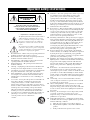 2
2
-
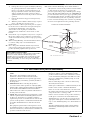 3
3
-
 4
4
-
 5
5
-
 6
6
-
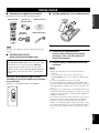 7
7
-
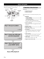 8
8
-
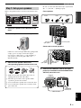 9
9
-
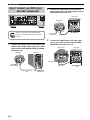 10
10
-
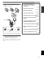 11
11
-
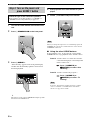 12
12
-
 13
13
-
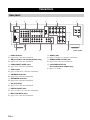 14
14
-
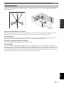 15
15
-
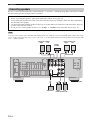 16
16
-
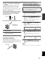 17
17
-
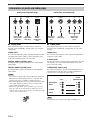 18
18
-
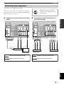 19
19
-
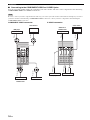 20
20
-
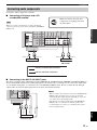 21
21
-
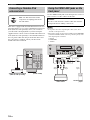 22
22
-
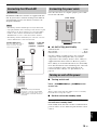 23
23
-
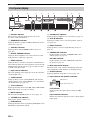 24
24
-
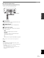 25
25
-
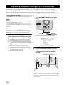 26
26
-
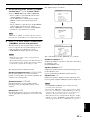 27
27
-
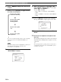 28
28
-
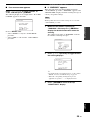 29
29
-
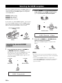 30
30
-
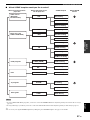 31
31
-
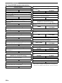 32
32
-
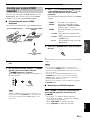 33
33
-
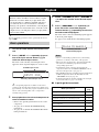 34
34
-
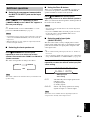 35
35
-
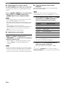 36
36
-
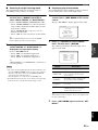 37
37
-
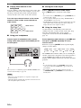 38
38
-
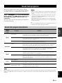 39
39
-
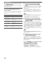 40
40
-
 41
41
-
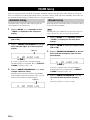 42
42
-
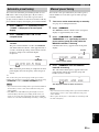 43
43
-
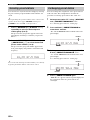 44
44
-
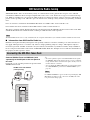 45
45
-
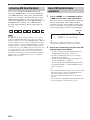 46
46
-
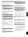 47
47
-
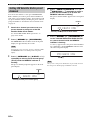 48
48
-
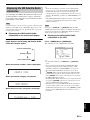 49
49
-
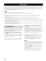 50
50
-
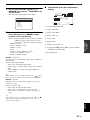 51
51
-
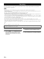 52
52
-
 53
53
-
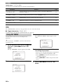 54
54
-
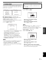 55
55
-
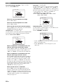 56
56
-
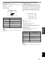 57
57
-
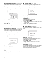 58
58
-
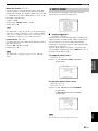 59
59
-
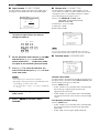 60
60
-
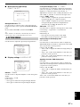 61
61
-
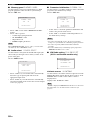 62
62
-
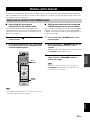 63
63
-
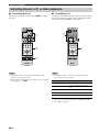 64
64
-
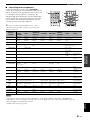 65
65
-
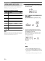 66
66
-
 67
67
-
 68
68
-
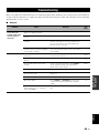 69
69
-
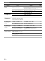 70
70
-
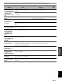 71
71
-
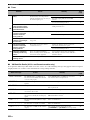 72
72
-
 73
73
-
 74
74
-
 75
75
-
 76
76
-
 77
77
-
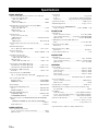 78
78
-
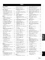 79
79
-
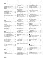 80
80
-
 81
81
-
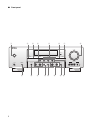 82
82
-
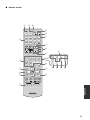 83
83
-
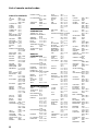 84
84
-
 85
85
-
 86
86
-
 87
87
-
 88
88
-
 89
89
-
 90
90
-
 91
91
-
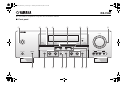 92
92
-
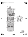 93
93


Yamaha RX-V461 Manual de usuario
- Categoría
- Receptores AV
- Tipo
- Manual de usuario
- Este manual también es adecuado para
en otros idiomas
- français: Yamaha RX-V461 Manuel utilisateur
- italiano: Yamaha RX-V461 Manuale utente
- English: Yamaha RX-V461 User manual
- Deutsch: Yamaha RX-V461 Benutzerhandbuch
- русский: Yamaha RX-V461 Руководство пользователя
- Nederlands: Yamaha RX-V461 Handleiding
- português: Yamaha RX-V461 Manual do usuário
- dansk: Yamaha RX-V461 Brugermanual
- polski: Yamaha RX-V461 Instrukcja obsługi
- čeština: Yamaha RX-V461 Uživatelský manuál
- svenska: Yamaha RX-V461 Användarmanual
- Türkçe: Yamaha RX-V461 Kullanım kılavuzu
- suomi: Yamaha RX-V461 Ohjekirja
- română: Yamaha RX-V461 Manual de utilizare
Artículos relacionados
-
Yamaha HTR-6160 El manual del propietario
-
-
Yamaha RX-V563 - AV Receiver Manual de usuario
-
-
-
-
Yamaha RX-V863 El manual del propietario
-
Yamaha RX-V657 El manual del propietario
-
-
