Glacier Bay LT2036WWHD Guía de instalación
- Categoría
- Grifos
- Tipo
- Guía de instalación

Pg 1 of 34
www.HOMEDEPOT.com IS2038
MCS 1/09/2019
Assembly & Installation Instructions
Model
LT2036WWHD
All-in-one laundry sink and cabinet
THANK YOU
We appreciate the trust and confidence you have placed in Glacier Bay through the
purchase of this laundry sink and cabinet. We strive to continually create quality products
designed to enhance your home. Visit us online to see our full line of products available for
your home improvement needs. Thank you for choosing Glacier Bay!

Pg 2 of 34
www.HOMEDEPOT.com IS2038
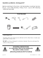
Questions, problems, missing parts?
Before returning to the store, call Glacier Bay Customer Service
8 a.m. - 7 p.m., EST, Monday - Friday, 9 a.m. - 6 p.m., EST, Saturday
1-855-HD-GLACIER
Cleaning Note:
Cleaning with a dry cloth may be sufficient, but for other stains or marks wipe
gently with a damp cloth.
DO NOT use strong detergents or abrasive cleaners, they may damage the
surface of this product.
Tools Needed
MOUNTING INSTRUCTIONS:
It is imperative that unit be fastened to
the wall for safety reasons.
(Mounting hardware NOT included)
Plumbers
Putty

Pg 3 of 34
www.HOMEDEPOT.com IS2038
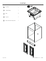
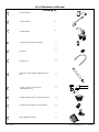
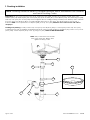
List of Parts
A
Sink Basin
1
B
Cabinet Body
1
C
Door
2
D
Top Trim
1
E
Hose Guard with Soap Dish
1
A
B
C
D
C
E

Pg 4 of 34
www.HOMEDEPOT.com IS2038
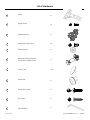
List of Hardware
Hinge
Mounting Plate
Hinge Screw
1
2
5
4
x 4
x 8
x 8
Door Bumper
3
x 4
Mounting Plate Screw
x 4
6
Adjustable Foot Assembly
(Foot, Bolt and Bolt Cap)
x 4
9
Screw Cap
7
x 24
Door Knob
8
x 2
Door Knob Screw
x 2
10
Trim Screw
x 2
11
Allen Wrench
x 1

Pg 5 of 34
www.HOMEDEPOT.com IS2038
List of Hardware continued
Lock Nut
14
x 1
Faucet Body
16
x 1
Basket Strainer with T-Washer and Nut
20
x 1
Plumbing Kit
Garden Hose Adapter with Washer
21
x 1
x 2
x 2
19
18
17
Supply Line
Tail piece with Tapered Washer and
Nut
P-Trap (consists of Trap Arm,
J-Bend and Nut)
x 1
Hose Weight with Nut
22
x 1
13
Faucet Hose
x 1
12
Faucet Head
x 1
Connecting Pipe with Washer
15
x 1

Pg 6 of 34
www.HOMEDEPOT.com IS2038
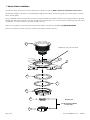
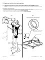
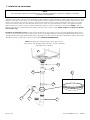
1.
Basket Strainer installation
Unscrew nut (20-F) and remove T-washer (20-E) from strainer body (20-A). NOTE: T-washer and nut will be used in step 9.
Disassemble strainer body (20-A), by unscrewing the large locknut (20-D) and removing the paper washer (20-C) and the
rubber
washer (20-B).
Apply a sufficient amount of plumbers putty (not included) between the strainer and sink basin (A). Insert strainer body (20-A)
through the drain hole in the sink basin (A).
Holding strainer body firmly in place, position rubber
washer (20-B) then the paper
washer (20-C) onto the strainer body under the sink basin (A).
Screw lock nut (20-D) onto the threaded shank of the strainer body (20-A) and tighten, DO NOT OVERTIGHTEN!
Remove any excess plumbers putty from strainer body (20-A) and sink basin (A).
plumbers putty (not included)
20-A
A
20-B
20-C
20-D
Unscrew nut.
T-washer and nut will be
used in step 9.
20-E
20-F

Pg 7 of 34
www.HOMEDEPOT.com IS2038
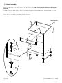
2.
Cabinet assembly
Attach top trim piece (D) to cabinet body (B) with trim screws (10). NOTE: Finished edges of cabinet body (B) face away
from wall.
Carefully lay the the cabinet body (B) on it’s back (unfinished edge side down) and attach the adjustable feet (6) to cabinet
body (B), using allen wrench (11).
Attach the bolt caps (6-B) to the large bolts (6-A), as shown.
B
6
6
D
6-A
6-B
Unfinished Edge
10

Pg 8 of 34
www.HOMEDEPOT.com IS2038
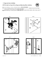
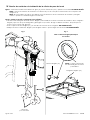
3.
Hinge and door installation
NOTE: Do Not Use Power Drill for Hinge and Mounting Plate installation.
Fig. 1: Fasten hinges (1) to doors (C) with hinge screws (2). DO NOT OVERTIGHTEN.
Fig. 2: Fasten mounting plates (3) to cabinet body (B) with mounting plate screws (4). NOTE: The long side of mounting
plates (3) point to the front of the unit. DO NOT OVERTIGHTEN.
Fig. 3:
F
asten hinges (1) to mounting plates (3). NOTE: hinges must be adjusted after installation. Refer to step 4, page 10.
Fig. 4: Fasten knob (8) to the doors (C) with door knob screws (9).
Fig. 2
Fig. 3
Fig. 1
3
1
C
1
2
B
3
4
Fig. 4
8
9
C

Pg 9 of 34
www.HOMEDEPOT.com IS2038
4.
Hinge adjustment
Loosen the hinge keyhole screw that secures the
hinge to the mounting plate.
Lateral Adjustment Screw: Allows for adjusting the door
2.5mm left or right.
Horizontal Adjustment Screw: Allows for adjusting the
door forward or backward.
Vertical Adjustment: Allows for adjusting the door up
or down.
+
+
+
+
+
+

Pg 10 of 34
www.HOMEDEPOT.com IS2038
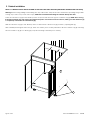
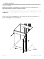
5.
Cabinet installation
NOTE: IT IS IMPERATIVE THAT UNIT BE FASTENED TO THE WALL FOR SAFETY REASONS (MOUNTING HARDWARE NOT INCLUDED).
Warning: Before cutting, drilling or hammering into any wall surface, verify the location of electrical, plumbing and gas lines.
Cutting any of these may cause serious injury. NOTE: We recommend mounting the cabinet directly into studs.
Place the cabinet body (B) in the desired position and place the sink basin (A) into cabinet body (B). NOTE: This is a snug
fit and the sink basin (A) may need to be worked into place. Press down on all four corners, making sure the sink basin (A)
is completely seated onto the cabinet body (B).
With the cabinet body (B) in the desired position, make sure the cabinet body (B) is level by adjusting feet (6).
After carefully removing the sink basin (A), insert wood shims (not included) between wall and cabinet body (B) until snug.
Attach cabinet body (B) to wall using appropriate mounting hardware (not included).
B
6

Pg 11 of 34
www.HOMEDEPOT.com IS2038
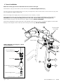
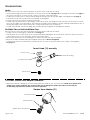
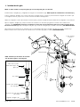
6.
Faucet installation
nut on underside of
faucet body (14)
connecting pipe with
washer (15)
faucet hose (13)
two o-rings
NOTE: Confirm that connecting pipe is tight to
the faucet AND hose.
faucet shank
22-A
NOTE: Faucet body (14) must be installed with the faucet handle on the right.
Install faucet body (14) and secure in place with locknuts (16). NOTE: Hand tighten locknuts (16).
Pass the faucet hose (13) through faucet body (14-A) and adjust the position of the faucet so that faucet hose (13) does
not rub against the edge of the sink hole.
Slide hose through hose weight (22-A) and nut (22-B) onto hose
assembly, as shown.
Attach the faucet hose (13) onto the connecting pipe with washer (15) by turning connecting pipe with washer (15).
IMPORTANT: Be sure to hold plastic fitting of the faucet hose with a wrench while turning connecting pipe (15).
Attach faucet hose (13) to the
faucet head (12). Tighten securely, DO NOT OVERTIGHTEN.
Attach the connecting pipe with washer (15) to the underside of the faucet body (14), by turning nut.
Tighten securely while
keeping connecting pipe with washer (15) from turning and loosening. DO NOT OVERTIGHTEN.
22-B
faucet handle
on the right
12
13
13
16
14
16
15
wrench fitting location

Pg 12 of 34
www.HOMEDEPOT.com IS2038
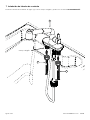
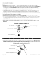
7.
Supply lines installation
faucet shank
Connect the water supply lines (17) onto faucet shanks and tighten with wrench. DO NOT OVERTIGHTEN.
17
17
14

Pg 13 of 34
www.HOMEDEPOT.com IS2038
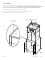
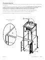
8.
Tub installation
Place a bead of silicone caulk/sealant (not included) around the top edge of the cabinet body (B), as shown.
Carefully set sink basin (A) into cabinet body (B). NOTE: This is a snug fit and the sink basin (A) may need to be worked into
place. Press down on all four corners, making sure the sink basin (A) is completely seated onto the cabinet body (B).
Insert screw caps (7) into exposed screw heads on the cabinet body (B).
Place bumpers (5) on doors (C) where they come in contact with the cabinet body (B).
Place hose guard with soap dish (E) into either side of the sink basin (A).
silicone caulk/sealant
(not included)
7
7
B
B
A
E
5
5
C
C

Pg 14 of 34
www.HOMEDEPOT.com IS2038
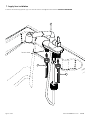
9.
Plumbing installation
NOTE: Keep connections loose until all
drain components are aligned, then
tighten securely by hand.
NOTE: Plumbing should be done by a qualified plumber and in accordance with National
and Local Plumbing Codes.
NOTE: Tapered side down
A
19-A
18-A
19-C
19-B
20-E
Preparation: Slip nut (19-C) onto trap-arm (19-A). Position two nuts (18-B and 20-F) and tapered washer (18-C) onto
tailpiece (18-A). Slip tailpiece (18-A) into J-bend (19-B). Slip tapered washer (18-C) down tailpiece (18-A) and fasten using nut (18-B).
Insert trap-arm (19-A) into J-bend (19-B) and hand tighten all nuts. Holding plumbing assembly in the desired position, measure
trap-arm (19-A) and tailpiece (18-A), to required length. Remove trap-arm (19-A) and tailpiece (18-A) and cut with a
hacksaw. NOTE: Cut untapered end of tailpiece (18-B) and trap-arm (18-A). NOTE: Be sure to remove burrs with a file or
sandpaper.
Installing new plumbing: Loosely connect trap-arm (19-A) and tailpiece (18-A) to J-bend (19-B). Fasten trap-arm (19-A)
to existing waste drain and tighten using existing hardware. Using T-washer (20-E) from strainer kit (20), place it on top of tail-
piece (18-A). Fasten tailpiece (18-A) to tub (A) using nut (20-F). NOTE: DO NOT OVERTIGHTEN.
18-C
18-B
20-F

Pg 15 of 34
www.HOMEDEPOT.com IS2038
10.
Supply lines to outlet shut off valve installation
Fig. 1: Connect the water supply lines (17) onto the shut off valves and tighten with wrench. DO NOT OVERTIGHTEN.
NOTE: Connect supply lines to shut off valve in full compliance with local code requirements.
NOTE: Turn on water supply and check for leaks on all supply and drain connections. Re-tighten connections as needed.
Fig. 2: Flush lines and check for leaks.
• Pull faucet head (12) out of the faucet spout and unscrew fitting. Holding the end of the faucet hose (13) down into sink,
turn faucet to warm water postion and full water flow, then repeat with cold water position.
• Re-attach faucet head (12) and washer to hose fitting. DO NOT OVERTIGHTEN.
• Check all faucet and drain connections. Re-tighten as needed. DO NOT OVERTIGHTEN.
outlet
shut off valves
17
17
Fig: 2
remove faucet head to flush away debris
Fig: 1
faucet hose (13)
faucet head (12)
NOTE: The notch on the faucet
head ring is at the bottom.

Pg 16 of 34
www.HOMEDEPOT.com IS2038
TROUBLESHOOTING
Leaks:
Be sure both hot and cold water supply lines are closed at the outlet shut off valves.
• Check all plumbing and faucet connections to locate source of leak. See page 14 for plumbing connections and page 11
for faucet connections. If source of leak cannot be located, check these items:
• Confirm that connector pipe, quick connector fitting and faucet stem are properly aligned and tightened, see page 11.
If necessary, loosen the connector pipe completely and re-tighten.
• Inspect pull-out hose and hose connectors for leaks.
• Confirm appropriate location for the weight on the pull-out hose. The weight should be located on the hose so that the
hose can be pulled out and recoiled back under the tub freely without kinking, catching anything underneath the tub, or
rubbing the edge of the center faucet hole, causing unnecessary wear to the hose.
• Confirm that all other connection fittings are properly threaded together and re-tighten if needed.
No Water Flow or Restricted Water Flow:
Be sure both hot and cold water supply lines are closed at the outlet shut off valves.
• Confirm proper connecting pipe installation, see page 11.
• Pull faucet head out of the faucet spout and unscrew fitting. Holding the end of the hose down into sink, turn faucet to
warm water postion to max, then repeat with cold water position.
• Remove the aerator head, by loosening with a wrench and then turn with your fingers.
• Remove any debris. Reinstall spring and re-tighten aerator head. Do not overtighten.
• Loosen each faucet and pull-out hose connection one at a time and inspect. Remove any debris and re-tighten.
See page 15.
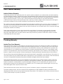
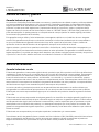
Faucet Head (12) assembly
Garden Hose Adapter (21)
OPTIONAL: Garden hose adapter installation
• Remove the faucet cartridge and attach the garden hose adapter (21) as shown below. NOTE: Use of garden hose
adapter may require installation of a vacum breaker (not included) for backflow prevention. Check with your
local building department to confirm local code requirements.
aerator head
sprayer button
button cover
garden hose adapter (21)
rubber washer
faucet head (12)
faucet head ring

Pg 17 of 34
www.HOMEDEPOT.com IS2038
Tub & Cabinet Warranty
Limited Lifetime Warranty
Glacier Bay products are manufactured with superior quality standards and workmanship and are backed by
our limited lifetime warranty. Glacier Bay products are warranted to the original consumer purchaser to be free of
defects in materials or workmanship. We will replace FREE OF CHARGE any product or parts that proves defective.
Simply, return the product / part to any of The Home Depot retail locations or call 1-855-HD Glacier
(1-855-434-5224) to receive the replacement item. Proof of purchase (original sales receipt) from the original
consumer purchaser must be made available for all Glacier Bay warranty claims.
This warranty excludes incidental/inconsequential damages and failures due to misuse, abuse or normal wear
and tear. This warranty excludes all industrial, commercial & business usage, whose purchasers are hereby,
extended a five year limited warranty from the date of purchase, with all other terms of this warranty applying
except the duration of warranty.
Some states and provinces do not allow the exclusion or limitation of incidental or consequential damages,
so the above limitations may not apply to you. This warranty gives you specific legal rights and you may
also have other rights that vary from state to state and province to province. Please see a store or contact
1-855-HDGlacier for more details.
Plumbing Warranty
Limited One Year Warranty
The manufacturer warrants to the original purchaser that this product will be free from defects in materials or
workmanship for a period of one year from the date of original purchase. This warranty only covers the proper
and intended use of this product. In the event of and bona fide warranty claim relating to this product, the
manufacturer will, at its election and sole discretion, provide a replacement product or a substantially similar
product. This replacement is the sole and exclusive remedy with respect to any warranty claim relating to this
product. Under no circumstances will the manufacturer’s liability exceed the purchase price of this product.
All costs of removing and reinstalling the product are the purchaser’s responsibility. Any alteration of this product or
use of this product in any manner other than its intended use is not covered by this warranty. The manufacturer
assumes no responsibility whatsoever for product installation during the limited one year warranty.
The manufacturer disclaims any and all warranties. The duration of any implied warranty which cannot be
disclaimed is limited to the time period as specified in the expressed warranty. The manufacturer shall not be
liable for incidental, consequential, or special damages arising out of or in connection with product use or
performance, except as may otherwise be accorded by law. This warranty gives specific rights, and you may
have other rights which vary from state to state.
The manufacturer shall not be liable for any special, incidental, and/or consequentail damages.
To obtain warranty service, call our customer service department at (302) 326-8203 for return authorization and
shipping instructions so that we may repair or replace the product. No warranty claim will be processed without
a copy of the receipt as proof of purchase.
Model #
LT2036WWHD

Pg 18 of 34
www.HOMEDEPOT.com IS2038
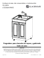
Instrucciones de ensamble e instalación
Modelo
LT2036WWHD
Fregadero para lavado de ropas y gabinete
todo en uno
¡GRACIAS!
Agradecemos la confianza que ha depositado en Glacier Bay a través de la adquisición
de este fregadero para lavado de ropas y gabinete. Nos esforzamos constantemente
en crear productos de calidad diseñados para embellecer su hogar. Visítenos en línea
y vea nuestra línea completa de productos para realizar mejoras en su hogar.
¡Gracias por elegir Glacier Bay!

Pg 19 of 34
www.HOMEDEPOT.com IS2038
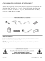
¿Tiene preguntas, problemas, le faltan piezas?
Antes de regresar a la tienda, llame al Servicio al Cliente de
Glacier Bay, de 8 a.m. - 7 p.m., Hora Estándar del Este, de
lunes a viernes, de 9 a.m. - 6 p.m., Hora Estándar del Este,
sábado 1-855-HD-GLACIER
Nota para limpieza:
Puede ser suficiente limpiar con un paño seco, pero para otras manchas o marcas,
limpie suavemente con un paño humedecido.
NO USE detergentes fuertes o limpiadores abrasivos; pueden dañar la superficie de
este producto.
Herramientas necesarias
INSTRUCCIONES DE MONTAJE:
POR RAZONES DE SEGURIDAD, ES FUNDAMENTAL QUE ESTA
UNIDAD SEA MONTADA A LA PARED.
(NO SE INCLUYE LA TORNILLERÍA DE MONTAJE)
Plumbers
Putty

Pg 20 of 34
www.HOMEDEPOT.com IS2038
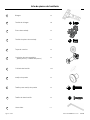
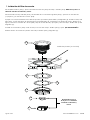
Lista de piezas
A
Fregadero
1
B
Cuerpo del gabinete
1
C
Puerta
2
D
Terminación superior
1
E
Protección de manguera con
jabonera
1
A
B
C
D
C
E

Pg 21 of 34
www.HOMEDEPOT.com IS2038
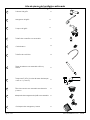
Lista de piezas de tornillería
Bisagra
Placa de montaje
Tornillo de bisagra
1
2
5
4
x 4
x 8
x 4
Tope de caucho
3
x 4
Tornillo de placa de montaje
x 4
6
Conjunto de pata regulable
(pata, perno y cubierta del perno)
x 4
9
Cubierta del tornillo
7
x 24
Manija de puerta
8
x 2
Tornillo para manija de puerta
x 2
10
Tornillo de terminación
x 2
11
Llave Allen
x 1

Pg 22 of 34
www.HOMEDEPOT.com IS2038
Lista de piezas de tornillería continuada
Contratuerca
14
x 1
Cuerpo del grifo
16
x 1
Filtro de canasta con arandela escalonada
y tuerca
20
x 1
Plumbing Kit
Adaptador de manguera de jardín con arandela
21
x 1
x 2
x 2
19
18
17
Tubería de suministro
Pieza de extremo con arandela cónica y
tuerca
Trampa en P (sifón) (consta de brazo de trampa,
codo en J y tuerca)
x 1
Contrapeso de manguera y tuerca
22
x 1
13
Manguera del grifo
x 1
12
Cabezal del grifo
x 1
Tubería de conexión con arandela
15
x 1

Pg 23 of 34
www.HOMEDEPOT.com IS2038
1.
Instalación del filtro de canasta
Desatornille la tuerca (20-F) y quite la arandela escalonada (20-E) del cuerpo del filtro (20-A). NOTA: En el paso 9 se
utilizarán arandela escalonada y tuerca.
Desensamble el cuerpo del filtro (20-A), desatornillando la contratuerca grande (20-D) y quitando la arandela de
papel (20-C) y la arandela de caucho (20-B).
Aplique una cantidad suficiente de masilla de plomero (no incluida) entre el filtro y el fregadero (A). Inserte el cuerpo del
filtro (20-A) a través del orificio de drenaje situado en el fregadero (A). Sosteniendo con firmeza el cuerpo del filtro en su
lugar, posicione la arandela de caucho (20-B), después la arandela de papel (20-C) sobre el cuerpo del filtro debajo del
fregadero (A).
Atornille la contratuerca (20-D) sobre el cuerpo roscado del cuerpo del filtro (20-A) y ajuste. ¡NO APRIETE DE MÁS!
Retire el exceso de masilla de plomero del cuerpo del filtro (20-A) y fregadero (A).
masilla de plomero (no incluida)
20-A
A
20-B
20-C
20-D
Desatornille la tuerca.
En el paso 9 se utilizarán
arandela escalonada y
tuerca.
20-E
20-F

Pg 24 of 34
www.HOMEDEPOT.com IS2038
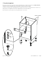
2.
Ensamble del gabinete
Fije la pieza de terminación superior (D) al cuerpo del gabinete (B) con tornillos de terminación (10). NOTA: Los bordes
acabados del cuerpo del gabinete (B) están orientados en dirección opuesta a la pared.
Coloque con cuidado el cuerpo del gabinete (B) apoyándolo sobre su fondo (con el borde lateral sin acabado hacia
abajo) y fije las patas regulables (6) al cuerpo del gabinete (B), usando la llave Allen (11).
Fije las cubiertas para pernos (6-B) a los pernos grandes (6-A), como se ilustra.
B
6
6
D
6-A
6-B
10
Borde sin acabado

Pg 25 of 34
www.HOMEDEPOT.com IS2038
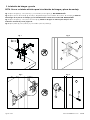
3.
Instalación de bisagra y puerta
NOTA: No use un taladro eléctrico para la instalación de bisagra y placa de montaje
Fig. 1: Fije las bisagras (1) a las puertas (C), con tornillos para bisagras (2). NO APRIETE DE MÁS.
Fig. 2: Fije las placas de montaje (3) al cuerpo del gabinete (B) con los tornillos de la placa de montaje (4). NOTA: El
lateral largo de las placas de montaje (3) está orientado hacia el frente de la unidad. NO APRIETE DE MÁS.
Fig. 3: Fije las bisagras (1) a las placas de montaje (3). NOTA: las bisagras se deben ajustar después de la
instalación. Consulte el paso 4, página 26.
Fig. 4: Fije la perilla (8) a las puertas (C) con tornillos para las perillas (9).
Fig. 2
Fig. 3
Fig. 1
3
1
C
1
2
B
3
4
Fig. 4
8
9
C

Pg 26 of 34
www.HOMEDEPOT.com IS2038
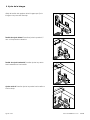
4.
Ajuste de la bisagra
Afloje el tornillo del agujero de la bisagra que fija la
bisagra a la placa de montaje.
Tornillo de ajuste lateral: Permite ajustar la puerta 2,5
mm a la izquierda o derecha.
Tornillo de ajuste horizontal: Permite ajustar la puerta
hacia adelante o hacia atrás.
Ajuste vertical: Permite ajustar la puerta hacia arriba o
hacia abajo.
+
+
+
+
+
+

Pg 27 of 34
www.HOMEDEPOT.com IS2038
5.
Instalación del gabinete
NOTA: POR RAZONES DE SEGURIDAD, ES FUNDAMENTAL QUE ESTA UNIDAD SEA MONTADA A LA PARED. (NO SE INCLUYE LA
TORNILLERÍA DE MONTAJE).
Advertencia: Antes de cortar, taladrar o martillar cualquier superficie de pared, verifique la ubicación de los conductos
eléctricos y las tuberías de agua y gas. Si interfiriese con cualquiera de estas, se podrían causar lesiones graves.
NOTA: Recomendamos montar el gabinete directamente en los soportes.
Coloque el cuerpo del gabinete (B) en la posición deseada y coloque el fregadero (A) dentro del cuerpo del gabinete
(B). NOTA: Este debe ser un calce perfecto y es posible que se deba ayudar para que el fregadero (A) quede en su lugar.
Presione sobre las cuatro esquinas, asegurándose de que el fregadero (A) esté totalmente asentado sobre el cuerpo
del gabinete (B).
Con el cuerpo del gabinete (B) en la posición deseada, asegúrese de que el cuerpo del gabinete (B) esté a nivel
ajustando las patas (6).
Después de retirar cuidadosamente el fregadero (A), inserte suplementos de madera (no incluidos) entre la pared y
el cuerpo del gabinete (B) hasta que esté bien ajustado.
Monte el cuerpo del gabinete (B) a la pared, usando tornillería de montaje apropiada (no incluida).
B
6

Pg 28 of 34
www.HOMEDEPOT.com IS2038
6.
Instalación del grifo
tuerca en la parte
inferior del cuerpo del
grifo (14)
tubería de conexión
con arandela
manguera del grifo (13)
dos o-rings
faucet shank
22-A
NOTA: Se debe instalar el cuerpo del grifo (14) con la manija del grifo a la derecha.
Instale el cuerpo del grifo (14) y asegúrelo en su lugar con contratuercas (16). NOTA: Apriete las contratuercas con la mano (16).
Pase la manguera del grifo (13) a través del cuerpo del grifo (14-A) y ajuste el posicionamiento del grifo de manera que
la manguera de este (13) no roce contra el borde del orificio del fregadero.
Deslice la manguera a través del contrapeso de esta (22-A) y la tuerca (22-B) sobre el ensamble de la manguera, como se ilustra.
Fije la manguera del grifo (13) sobre la tubería de conexión con arandela (15) girando la tubería de conexión con
arandela (15). IMPORTANTE: Asegúrese de mantener el accesorio de la manguera del grifo con una llave mientras gira la
tubería de conexión (15). Fije la manguera del grifo (13) al cabezal del grifo (12). Apriete con firmeza, ¡NO APRIETE DE MÁS!
Fije la tubería de conexión con la arandela (15) a la parte inferior del cuerpo del grifo (14) girando la tuerca. Apriete con
firmeza mientras evita que la tubería de conexión con la arandela (15) gire y se suelte. ¡NO APRIETE DE MÁS!
22-B
manija del grifo a
la derecha
12
13
13
16
16
14
15
NOTA: Confirme que la tubería de conexión
esté ajustada al grifo Y a la manguera.
ubicación de aplicación
de la llave

Pg 29 of 34
www.HOMEDEPOT.com IS2038
7.
Instalación de tuberías de suministro
Conecte la tubería de suministro de agua (17) con los cuerpos del grifo y apriete con una llave. NO APRIETE DE MÁS.
cuerpo del grifo
17
17
14

Pg 30 of 34
www.HOMEDEPOT.com IS2038
8.
Instalación de la tina
Coloque una gota de sellador/masilla de silicona (no incluido) alrededor del borde superior del cuerpo del gabinete (B),
como se ilustra.
Coloque el fregadero (A) con cuidado dentro del cuerpo del gabinete (B). NOTA: Este debe ser un calce perfecto y es
posible que se deba ayudar para que el fregadero (A) quede en su lugar. Presione sobre las cuatro esquinas,
asegurándose de que el fregadero (A) esté totalmente asentado sobre el cuerpo del gabinete (B).
Inserte las cubiertas para tornillos (7) en cada cabeza de tornillo expuesta en el cuerpo del gabinete (B).
Coloque topes (5) en las puertas (C) donde entran en contacto con el cuerpo del gabinete (B).
Coloque la protección de manguera con jabonera (E) a cada lado del fregadero (A).
sellador/masilla de silicona
(no incluido)
7
7
B
B
A
E
5
5
C
C

Pg 31 of 34
www.HOMEDEPOT.com IS2038
9.
Instalación de conexiones
NOTA:
Las conexiones deben ser realizadas por un plomero calificado y según los códigos nacionales
y locales de conexiones.
NOTA: Mantenga las conexiones flojas hasta que todos los
componentes del desagüe estén alineados, después apriételas
manualmente con firmeza.
NOTA: Lado cónico hacia abajo
A
19-A
18-A
19-C
19-B
20-E
Preparativos: Deslice la tuerca (19-C) sobre el brazo de la trampa (sifón)(19-A). Coloque dos tuercas (18-B y 20-F) y la
arandela cónica (18-C) sobre la pieza del extremo (18-A). Deslice la pieza del extremo (18-A) dentro del codo en J (19-B).
Deslice la arandela cónica (18-C) por la pieza del extremo (18-A) y sujétela usando la tuerca (18-B). Inserte el brazo de la
trampa (19-A) dentro del codo en J (19-B) y apriete todas las tuercas con la mano. Sosteniendo el conjunto de conex-
iones en la posición deseada, mida el brazo de la trampa (19-A) y la pieza del extremo (18-A) a la longitud requerida.
Retire el brazo de la trampa (19-A) y la pieza del extremo (18-A) y corte con una sierra para metales. NOTA: Corte el
extremo ahusado de la pieza del extremo (18-B) y del brazo de la trampa (18-A). NOTA: Asegúrese de quitar las rebabas
con una lima o lija.
Instalación de conexiones nuevas: Conecte sin apretar el brazo de la trampa (19-A) y la pieza del extremo (18-B) con el
codo en J (19-B). Fije el brazo de la trampa (19-A) al tubo de desagüe existente y apriete la tornillería existente. Usando la
arandela escalonada (20-E) del kit del filtro (20), colóquela en la parte superior de la pieza del extremo (18-A). Fije la pieza
del extremo (18-A) a la tina (A) usando la tuerca (20-F). NOTA: NO APRIETE DE MÁS.
18-C
18-B
20-F

Pg 32 of 34
www.HOMEDEPOT.com IS2038
10.
Tuberías de suministro a la instalación de la válvula de paso de la red
Figura 1: Conecte las tuberías de suministro de agua (17) con las válvulas de paso y apriete con una llave. NO APRIETE DE MÁS.
NOTA: Conecte las tuberías de suministro a la válvula de paso en completa conformidad con los requisitos del
código local.
NOTA: Abra el suministro de agua para verificar si hay pérdidas en todas las conexiones de suministro y desagüe.
Vuelva a apretar las conexiones según sea necesario.
Figura 2: Limpie las tuberías y compruebe si hay pérdidas.
• Jale del cabezal del grifo desde el surtidor del grifo y desatornille el accesorio. Sosteniendo el extremo de la manguera
del grifo (13) hacia abajo en el fregadero, gire el grifo a la posición del agua caliente al máximo, después repita la
acción con la posición del agua fría.
• Vuelva a fijar el cabezal del grifo (12) y la arandela al accesorio de la manguera. NO APRIETE DE MÁS.
• Verifique todas las conexiones del grifo y de desagüe. Vuelva a apretar según sea necesario. NO APRIETE DE MÁS.
válvula de
paso de la red
Fig: 2
retire el cabezal del grifo para limpiar
los residuos
17
17
Fig: 1
manguera del grifo (13)
cabezal del grifo (12)
NOTA: La muesca situada en
el cabezal del grifo está en la
parte inferior.

Pg 33 of 34
www.HOMEDEPOT.com IS2038
SOLUCIÓN DE PROBLEMAS
Pérdidas:
Asegúrese de que las líneas de suministro de agua fría y caliente estén cerradas en la válvula de paso de la red.
• Verifique todas las conexiones y grifos para ubicar el origen de la pérdida. Vea las conexiones de tuberías en la página 30
y las conexiones de grifos en la página 27. Si el origen de la pérdida no se pudiera ubicar, verifique estos elementos:
• Confirme que la tubería de conexión, el accesorio de acople rápido y el vástago estén correctamente alineados y apreta
dos, ver página 27. Si fuese necesario, afloje la tubería de conexión por completo y vuelva a apretar.
• Inspeccione la manguera extraíble y los conectores de la manguera para detectar pérdidas.
• Confirme el lugar apropiado para el contrapeso de la manguera extraíble. Se debe colocar el contrapeso sobre la
manguera de modo que se la pueda extraer y retraer bajo la tina libremente, sin torcerla, ni apresar cualquier cosa
bajo la tina, o rozar el borde del orificio central del grifo, provocando el desgaste innecesario de la manguera.
• Confirme que todos los otros accesorios de conexión estén adecuadamente roscados y vuelva a apretarlos si fuese necesario.
Sin flujo de agua o Flujo de agua restringido:
Asegúrese de que las líneas de suministro de agua fría y caliente estén cerradas en la válvula de paso de la red.
• Verifique la correcta instalación de la tubería de conexión, ver página 27.
• Jale del cabezal del grifo desde el surtidor del grifo y desatornille el accesorio. Sosteniendo el extremo de la manguera
hacia abajo en el fregadero, gire el grifo a la posición del agua caliente al máximo, después repita la acción con la
posición del agua fría.
• Retire el cabezal del aireador y la arandela aflojándolo con una llave y luego gírelo con los dedos.
• Retire los residuos. Vuelva a instalar el resorte y vuelva a apretar el cabezal del aireador. No apriete de más.
• Afloje cada grifo y conexión de manguera extraíble de a uno por vez y revise. Retire los residuos y vuelva a apretar,
ver pág. 31.
Ensamble del cabezal del grifo (12)
cabezal del aireador
botón del rociador
tapa del botón
aro del cabezal del grifo
Adaptador de manguera de jardín (21)
OPCIONAL: INSTALACIÓN DEL ADAPTADOR DE MANGUERA DE JARDÍN
• Quite el cartucho del grifo y fije el adaptador de manguera de jardín (21) como se muestra abajo. NOTA: Para usar un
adaptador de manguera de jardín puede ser necesario instalar un interruptor de vacío (no incluido) para evitar el reflujo.
Confirme los requisitos legales locales con su departamento regional de edificación.
adaptador de manguera
de jardín (21)
arandela de caucho
cabezal del grifo (12)

Pg 34 of 34
www.HOMEDEPOT.com IS2038
Modelo #
LT2036WWHD
Garantía de bañera y gabinete
Garantía limitada de por vida
Los productos Glacier Bay están fabricados con normas y manufactura de calidad superior y están respaldados
por nuestra garantía limitada de por vida. Los productos Glacier Bay garantizan al comprador consumidor
original que están libres de defectos en materiales o manufactura. Reemplazaremos SIN CARGO cualquier
producto o partes que estén defectuosas. Simplemente devuelva el producto/ parte a cualquiera de los
lugares de venta por menor de The Home Depot o llame al 1-855-HD Glacier (1-855-434-5224) para recibir la
parte de reemplazo. Se debe presentar un comprobante de compra (recibo de venta original) para todos
los reclamos bajo garantía de Glacier Bay.
Esta garantía excluye daños y fallas incidentales o emergentes debido a uso indebido, abuso o desgaste
normal. Esta garantía excluye todo uso industrial, comercial o institucional realizado por los compradores a
los que se le extiende esta garantía limitada de cinco años a partir de la fecha de compra, siendo de
aplicación todos los demás términos de esta garantía, excepto la duración de la misma.
Algunos estados y provincias no permiten la exclusión o limitación de daños incidentales o emergentes, por
ello las limitaciones previamente enunciadas pueden no serle aplicables. Esta garantía le confiere derechos
legales específicos y es posible que tenga otros derechos que pueden variar de estado a estado y de provincia
a provincia. Para ver más detalles concurra a una tienda o contacte a 1-855-HDGlacier.
Garantía de fontanería
Garantía limitada de un año
El fabricante garantiza al comprador original de este producto que dicho producto está libre de defectos en
materiales o mano de obra por un período de un año a partir de la fecha de compra original. Esta garantía
cubre solamente el uso adecuado y debido de este producto. En el caso de un reclamo de garantía de
buena fe relacionado con este producto, el fabricante, a su elección y a su exclusiva discreción, proporc
ionará un reemplazo del mismo o de un producto sustancialmente similar. Este reemplazo constituirá el único
recurso exclusivo con respecto a reclamos bajo garantía en relación con este producto. La responsabilidad
del fabricante en ningún caso excederá el precio de compra del producto.
Los costos de retirar y reinstalar el producto son responsabilidad del comprador. No están cubiertos por
esta garantía la modificación de este producto ni el uso del mismo de una manera que no sea la debida.
El fabricante no asume responsabilidad alguna por la instalación del producto durante la garantía limitada
de un año.
El fabricante no se hace responsable de ninguna garantía. La duración de cualquier garantía implícita que
no se puede excluir está limitada al lapso convenido según se indica en la garantía expresa. El fabricante no
será responsable de ningún daño incidental o consecuente, o daños especiales que se produzcan o estén
relacionados con la utilización del producto o su desempeño excepto que la ley indique lo contrario. Esta
garantía le otorga derechos legales específicos, y usted además puede tener otros derechos que varían de
estado a estado.
El fabricante no se responsable por cualquier especiales, incidentales y/o consecuentes.
Para obtener servicio de garantía, llame a nuestro servicio al cliente al (302) 326-8203 para recibir instrucciones
sobre la autorización de devolución y envío de modo que podamos reparar o reemplazar el producto.
Ninguna reclamación será procesada sin copia del recibo como prueba de compra.
-
 1
1
-
 2
2
-
 3
3
-
 4
4
-
 5
5
-
 6
6
-
 7
7
-
 8
8
-
 9
9
-
 10
10
-
 11
11
-
 12
12
-
 13
13
-
 14
14
-
 15
15
-
 16
16
-
 17
17
-
 18
18
-
 19
19
-
 20
20
-
 21
21
-
 22
22
-
 23
23
-
 24
24
-
 25
25
-
 26
26
-
 27
27
-
 28
28
-
 29
29
-
 30
30
-
 31
31
-
 32
32
-
 33
33
-
 34
34


Glacier Bay LT2036WWHD Guía de instalación
- Categoría
- Grifos
- Tipo
- Guía de instalación
en otros idiomas
Artículos relacionados
-
Glacier Bay 7043-104BN Guía de instalación
-
-
-
-
-
-
-
-
-
