
LS L &LB11
ELOWE
For use with Broan Elite and NuTone Premier Hoods.
Page 1
FOR DOMESTIC COOKING ONLY
WARNING WARNING
TO REDUCETHE RISK OF FIRE, ELECTRIC SHOCK, OR iNJURY
TO PERSONS, OBSERVE THE FOLLOWING:
1. Use this unit only in the manner intended by the manufacturer. If
you have questions, contact the manufacturer at the address or
telephone number listed in the warranty.
2. Before servicing or cleaning unit, switch power off at service panel
and lock the service disconnecting means to prevent power from
being switched on accidentally. When the service disconnecting
means cannot be locked, securely fasten a prominent warning
device, such as a tag, to the service panel.
3. Installation work and electrical wiring must be done by a qualified
person(s) in accordance with all applicable codes and standards,
including fire-rated construction codes and standards.
4. Sufficient air is needed for proper combustion and exhausting of
gases through the flue (chimney) offuel burning equipment to pre-
vent backdrafting. Follow the heating equipment manufacturer's
guideline and safety standards such as those published by the
National Fire Protection Association (NFPA), and the American
Society for Heating, Refrigeration and Air Conditioning Engineers
(ASHRAE), and the local code authorities.
5. When cutting or drilling into wall or ceiling, do not damage electri-
cal wiring and other hidden utilities.
6. Ducted fans must always be vented to the outdoors.
7. To reduce the risk of fire, use only metal ductwork.
8. Ifthis unit is to be installed over a tub or shower, it must be marked
as appropriate for the application and be connected to a GFCI
(Ground Fault Interrupter) - protected branch circuit.
9. Never place a switch where it can be reached from a tub or
shower.
10.This unit must be grounded.
TO REDUCE THE RISK OF A RANGE TOP GREASE FIRE:
1. Never leave surface units unattended at high settings. Boilovers
cause smoking and greasy spillovers that may ignite. Heat oils
slowly on low or medium settings.
2. Always turn hood ON when cooking at high heat or when flambe-
ing food (i.e. Crepes Suzette, Cherries Jubilee, Peppercorn Beef
Flambe').
3. Clean ventilating fans frequently. Grease should not be allowed
to accumulate on fan or filter.
4. Use proper pan size. Always use cookware appropriate for the
size of the surface element.
TO REDUCETHE RiSK OF INJURYTO PERSONS INTHE EVENT
OFA RANGETOP GREASE FIRE, OBSERVETHE FOLLOWING:*
1. SMOTHER FLAMES with a close-fitting lid, cookie sheet, or
metal tray, then turn off the burner. BE CAREFULTO PREVENT
BURNS. Ifthe flames do not go out immediately, EVACUATE AND
CALL THE FIRE DEPARTMENT.
2. NEVER PICK UPA FLAMING PAN -You may be burned.
3. DO NOT USE WATER, including wet dishcloths or towels -violent
steam explosion will result.
4. Use an extinguisher ONLY if:
A. You know you have a Class ABC extinguisher and you already
know how to operate it.
B. The fire is small and contained in the area where it started.
C. The fire department is being called.
D. You can fight the fire with your back to an exit.
* Based on "Kitchen Fire Safety Tips" published by NFPA.
CAUTION
1. For general ventilating use only. Do not use to exhaust hazardous
or explosive materials and vapors.
2. To avoid motor bearing damage and noisy and/or unbalanced
impellers, keep drywall spray, construction dust, etc. off power
unit.
3. If ventilator is installed in an unconditioned space (such
as an attic): Surround the ventilator with thermal insulation - to
minimize possible condensation.
4. Please read specification label on product for further information
and requirements.
TABLE OF CONTENTS
This manual is divided into sections as follows:
• "TYPICAL INSTALLATION"
This section shows a common installation.
- Mounting (New Frame Construction)
- Mounting (Existing Frame Construction)
- Mounting Using Hanger Kit (included)
- Ducting (Horizontal blower discharge)
- Wiring
• "MOUNTING OPTIONS"
• "WIRING PLATE POSITION"
• "DUCTING OPTIONS"
- Blower Discharge Positions
- Ducting (Vertical blower discharge)
• "USE AND CARE"
• "SERVICE PARTS"
• "WARRANTY"
installer: Leave this manual with
the homeowner.
Homeowner: Use and Care
information on page 4.

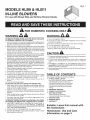
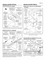
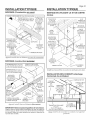
TYPICAL iNSTALLATiON
MOUNTING (New Frame Construction)
10" ROUND DUCT
(OUTLET) 8" X 12"TO
10" ROUND
/TRANSITION
(MALE)
8"X 12"TO
10" ROUND
TRANSITION
(FEMALE)
o" ROUND
I
GRILLE NUT
(Install into square
holes in housing)
Ventilator
factory-shipped
in straight-through
discharge position.
MOUNTING
BRACKETS
CEILING
JOIST
(24" centers
ACCESS I shown)
PANEL _. ACCESS PANEL
SCREW
Factory-shipped unit installed in new construction.
MOUNTING (Existing Frame Construction)
8"X 12"TO
10" ROUND
TRANSITION
(MALE) _
lO" ROUND
DUCT
(OUTLET)
8"X 12"TO 10" ROUND
10" ROUND DUCT (INTAKE)
TRANSITION
(FEMALE)
MOUNTINd
BRACKETS
CEILING
JOIST
(24"
centers
shown)
Ventilator factory-shipped
in straight-through
discharge position.
MOUNTING
SCREWS
-- GRILLE NUT
I (Install into
_ho square
les in hous-
v_,_ ing)
ACCESS
ACCESS J PANEL
PANEL SCREW
FactolT-shipped unit installed in existing; const,'uction.
Page 2
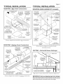
TYPICAL INSTALLATION
MOUNTING USING HANGER KiT (included)
8" X 12" TO
10" ROUND HANGER
TRANSITION KIT BOLT
(FEMALE) & WASHER
EXTENSION
SPRING
HANGER 10" ROUND
KIT CHAIN DUCT (INTAKE)
I
HANGER KIT
EYE-BOLT
8"X 12"TO
10" ROUND HANGER
TRANSITION KIT NUT &
(MALE) WASHER
/
lO" ROUND
DUCT
(OUTLET)
MOUNTING
BRACKET
i
I
@ GRILLE NUT
, _ (Install into
_ ! square holes in
_i_"_ housing)
cc ss
PANEL __ PANEL SCREW
BlowerJbctory-shipped in straight-through
discharge position.
DUCTING (Horizontal blower discharge)
10"
ROUND
DUCT
/_ ROOF CAP
8"X 12"TO
10" ROUND
TRANSITION
(MALE) ROUND
DUCT \
8"X 12"TO 10" ROUND
TRANSITION (FEMALE) 10" ROUND
ELBOW
L
LWALL
CAP
Two ways to connect ductwork to aJbctolT-shipped unit.
IMPORTANT: Remove shipping tape from damper
Remove the shipping tape from the damper flap and make sure that
damper flap opens and closes freely inside the ductwork. Use duct
tape to make ductwork connections secure and air-tight.

WiRiNG
Page 3
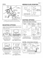
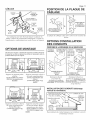
WIRING PLATE POSITION
BLACK
TO
BLACK EDGE
OF HOUSING
GROUND TO
WIRING PLATE
WIRING
/PLATE
WHITE
TO
WHITE
120 VAC LINE IN
(from range hood)
Ventilator can be wired f!'om outside of housing.
Use UL approved connectors to wire per local codes.
VERTICAL
POWER CABLE
CONNECTION
I
HORIZONTAL POWER
CABLE CONNECTION
I
l/Viring plate mounts to side or top qf housing.
DUCTING OPTIONS
BLOWER DISCHARGE POSiTiONS
MOUNTING OPTIONS
1_-20 hex nuts secure mounting brackets to housing. Loosen and
re-tighten or remove and replace nuts as necessary for desired
mounting bracket position.
Factory-Shipped 11/8"
Straiqht-Throuqh [_ M_X.
Discharg#_ _
[_ 22" ===_ f
_=0 O h
Factory-Shipped _J
Straiqht-Throuqh | lyi'
I.-- 18"--M
Mounting brackets in
Jacmry-shipped position -
mounted directly to joists.
(Outlet parallel to joists.)
(.Newconstruction)
Mounting b/ackets flipped
over and mounted to ad-
ditionalj?aming.
(Outlet perpendicular to joists.)
(_Newor Existing_construction)
MOVABLE DUCT
PANEL "CONNECTOR
DUCT
CONNECTOR
(intake)
Housing DUCT
rotated & mov- CONNECTOR
able panel cov- (outlet)
ers previous
open side.
DUCT
CONNECTOR
(intake)
MOVABLE
PANEL
(Change to this
location'
Ventilator shown in
straight-through discharT_e
position. (Facto1T shipped)
Ventilato/ shown in
angle discharge position.
(('hange movable panel m
new location as shown.)
F------q
'='HousingCon-==H
verted to R_iiiiiiii&___J
I Anqle Discharqe | 1½"
I,,i 18"
Factory-Shipped
_ Straiqht-ThrouqhDiechar_ _
[,_-'_ 22" _
Mounting brackets flipped
over and mounted mad-
ditional,f!"aming.
(Outlet vertical.)
(New or Existing construction)
Mounting brackets flipped
over and mounted to top _
housing. Housing secured
with cables.
(Outlet parallel to joists.)
(_Newor Existing_construction)
DUCTING (Vertical blower discharge)
8" X 12" TO
10" ROUND
TRANSITION
(MALE)
8" X 12"TO 10"
ROUND
TRANSITION
(FEMALE) _
lO" ROUND
DUCT
ROOF CAP
10" ROUND
DUCT
Typical ductwork connection to aventilato," conve/ted to
right-angle discharge.

USE AND CARE
Follow wiring instructions packed with range hood, and adhere to
all local and state codes, and the National Electrical Code.
_lb ARNING: To reduce the risk of electric shock,
disconnect from power supply before servicing.
Page 4
To clean blower assembly: Remove access panel, unplug blower
from housing, remove blower mounting nuts, and carefully remove
blower from housing. Use appropriate vacuum attachment or a soft
cloth and mild soap or detergent to clean blower discharge area and
wheel. DO NOT ALLOW WATER TO ENTER MOTOR. Make sure
blower assembly is completely dry before reinstalling.
Motor is permanently lubricated. Do not oil or disassemble motor.
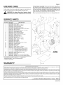
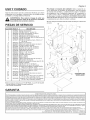
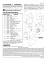
SERVICE PARTS
KEY PART NO.
1 97014853
2 99150415
3 98009520
4 97014784
5 97014728
6 99150591
7 97006142
8 99150471
9 98005512
10 99420470
11 98009531
12 93150487
13 98005513
14 99400035
15 97014788
16 99260477
17 99200202
18 97014785
19 99080490
99080491
20 93260447
21 98009516
22 99020286
23 98009514
24 99150417
25 98009513
+ 97016794
NO. DESCRiPTiON
97016795
26 98009532
27 99150472
28 97016791
29 99610015
30 99610028
Damper Flap
Screw, #8B x 1A* (16 req.)
Duct Connector (2 req.)
Housing Assembly
Mounting Bracket (2 req.)
Mounting Screw, #10-12 x .625 (4 req.)
Wiring Harness
Ground Screw, #10-32 x 1/2"(2 req.)
Wiring Adapter Plate
Access Panel Nut (4 req.)
Movable Housing Panel
Screw, #10-24 x .375* (8 req.)
Outlet Box Cover
Strain Relief Bushing
Motor Bracket
Whiz Nut, 1A-20" (11 req.)
Screw, 1A-20 x 1/2"(5 req.)
Blower Scroll
Motor (HLB9)
Motor (HLB11)
Nut, Hex Flange 5/16-18" (5 req.)
Support Bracket
Blower Wheel
inlet Ring
Screw, #8-18 x 1A* (5 req.)
Scroll Support Channel
Blower Assembly Complete (HLB9)
(Includes Key Nos. 15 thru 25)
Blower Assembly Complete (HLB11)
(Includes Key Nos. 15 thru 25)
Access Cover
Access Cover Screw (4 req.)
Hanger Kit
Transition, 8"x 12"to 10" Round, Male
Transition, 8" x 12" to 10" Round, Female
Order replacement parts by PART NO.- not by KEY NO.
* Standard hardware - may be purchased locally.
+ Not shown assembled.
WARRANTY
1 2
'/
29
\
4
/
\13 J
14
O I
5
\12
3 2
18
11 23
16 BLOWER
ASSEMBLY
BROAN-NUTONEONEYEARLIMITEDWARRANTY
Broan-NuTonewarrantstothe originalconsumerpurchaserof itsproductsthat suchproductswill befreefromdefectsin materialsor workmanshipfor aperiodofoneyearfromthedateof originalpurchase.THEREARENO
OTHERWARRANTIES,EXPRESSORIMPLIED,INCLUDING,BUTNOTLIMITEDTO,IMPLIEDWARRANTIESOFMERCHANTABILITYORFITNESSFORA PARTICULARPURPOSE.
Duringthisone-yearperiod,Broan-NuTonewill,atitsoption,repairor replace,withoutcharge,anyproductor partwhichisfoundtobedefectiveundernormaluseandservice.
THISWARRANTYDOESNOTEXTENDTOFLUORESCENTLAMPSTARTERS,TUBES,HALOGENANDINCANDESCENTBULBS,FUSES,FILTERS,DUCTS,ROOFCAPS,WALLCAPSANDOTHERACCESSORIESFORDUCTING.
Thiswarrantydoesnotcover(a) normalmaintenanceandserviceor (b)anyproductsor partswhichhavebeensubjectto misuse,negligence,accident,impropermaintenanceor repair(otherthanby Broan-NuTone),faulty
installationorinstallationcontraryto recommendedinstallationinstructions.
Thedurationofanyimpliedwarrantyislimitedtotheone-yearperiodasspecifiedfortheexpresswarranty.Somestatesdonotallowlimitationonhowlonganimpliedwarrantylasts,sotheabovelimitationmaynotapplytoyou.
BROAN-NUTONE'SOBLIGATIONTOREPAIRORREPLACE,ATBROAN-NUTONE'SOPTION,SHALLBETHEPURCHASER'SSOLEANDEXCLUSIVEREMEDYUNDERTHISWARRANTY.BROAN-NUTONESHALLNOTBELIABLE
FORINCIDENTAL,CONSEQUENTIALORSPECIALDAMAGESARISINGOUTOFORINCONNECTIONWITHPRODUCTUSEORPERFORMANCE.Somestatesdo notallowtheexclusionorlimitationof incidentalorconsequential
damages,sotheabovelimitationorexclusionmaynotapplytoyou.
Thiswarrantygivesyouspecificlegalrights,andyoumayalsohaveother rights,whichvaryfromstateto state.Thiswarrantysupersedesall priorwarranties.
Toqualifyforwarrantyservice,youmust(a)notifyBroan-NuToneattheaddressortelephonenumberbelow,(b)givethemodelnumberandpartidentificationand(c)describethenatureofanydefectintheproductor part.At
thetimeofrequestingwarrantyservice,youmustpresentevidenceoftheoriginalpurchasedate. Broan-NuToneLLC,926W.StateStreet,Hartford,Wisconsin53027 www.broan.com 800-558-1711
Broan-NuToneCanada,Inc.,1140TristarDrive,Mississauga,OntarioL5T1H9 www.broan.ca 877-896-1119
99043702E

EL
Por uso con
Y L811 TAJE f
LI
campanasdeBroanElitey NuTonePremier.
P_gina 5
PARA COCINAR EN
ADVERTENCIA
PARAREDUCIRELRiESGODEINCENDIO,GOLPEELECTRiCO,0LESi6N
APERSONAS,OBSERVELOSIGUIENTE:
1. Useesta unidad solamente de la manera indicada por el fabricante. Si
tiene preguntas, p6ngaseen contacto con elfabricante a la direcci6n o
teldono que aparecenen lagaranfia.
2. Antes de limpiar ode porteren servicio la unidad,apagueel interruptor
en el paneldeservicio, y asegure el panel deservicio paraevitar que se
encienda accidentalmente. Cuando el dispositivo para desconectar el
servicio el_ctrico no puede ser cerrado con alg_ntipo detraba, sujete
fuertementeal paneldeservicio, unaetiquetadeadvertenciaprominente.
3. Eltrabajo de instalaci6n y cableadoel_ctrico deben estar hechos por
personal capacitado de acuerdo con todos los c6digos y estD.ndares
aplicaNes, incluyendo c6digos y estD,ndaresde construcci6n a prueba
de incendios.
4. Senecesitasuficienteaire parala combusti6n y extracci6nde gasespor
lachimeneadelequipoque quemacombustible paraevitarla retrogresi6n
delas llamas.SigalasdirectricesdelfabricanteyestD,ndaresde seguridad
como los publicados por la Asociaci6n Nacional de Protecci6n Contra
Incendios(o porsus sighs eningles NFPA),y laSociedadAmericanade
Ingenieros de Calefacci6n,Refrigeraci6n, y Aire Acondicionado (o pot
sus sigles en ingl6sASHRAE),y los c6digos de las autoridadeslocales.
5. Cuando corte o taladre en una pared o cielo raso, no da_e cableado
el_ctrico o instalaciones novisibles.
6. Ventiladores con conductos siempre debenextraer hacia elexterior.
7. Parareducir el riesgo de incendio,uses61oductos de metal.
8. Siesta unidadvaainstalarsesobre una ba_eraoducha,debemarcD.rsela
como correcta para dicha aplicaci6n y debeconectarse a un protegido
GFCI(Cortacicuito Accidental aTierra).
9. Nuncainstale un interruptordonde sepuedaalcanzardesdeuna ba_era
o ducha.
10. Estaunidad sedebeconectar atierra.
PARAREBUCIRELRIESGOBEINCENBIOBEBIBOAGRASAACUIVIULADA
ENLASHORNiLLAS:
1. Nuncadejesin atender lasunidadesdesuperficie cuandotenganajustes
altos. Los reboses puedenprovocar humo y derrames grasosos quese
puedenincendiar.Calientelentamenteelaceiteenunajuste bajoomedio.
2. Siempre ENCIENDAlacampana cuando cocine con altatemperatura o
cuando cocine alimentos que sepuedan incendiar.
3. Limpie con frecuencia los ventiladores. No debe permitir que la grasa
se acumule en elventilador ni enel filtro.
4. Utilice un sart_n de tama_o adecuado.Siempre utilice el utensilio ade-
cuado al tama_o del elemento desuperficie.
PARAREDUCIRELRIESGOBELESIONAPERSONASRESULTADODEUN
INCENBIOBEBiDOAGRASAACUMULABAENLASHORNiLLAS,PROCURE
LOSiGUiENTE:*
1. AHOGUELASLLAMAScon unatapaajustadao charolade metal,despu_s
apaguela hornilla.TENGACUIDADOA FiNDEEVITARQUEMADURAS.Si
lasllamas no seapagande inmediato,EVACUEYAVISEA LOS BOMB-
EROS.
2. NOLEVANTENUNCA UNASARTENQUEESTEEN LLAMAS- Usted se
podrD,quemar.
3. NOUTILICEAGUA,incluyendotoallas decocinamojadas- puederesultar
unaexplosi6n devapor violent&
CASA SOLAMENTE
ADVERTENCIA
4. Utilice un extinguidor SOLAMENTEsi:
A. Usted sabe quetiene un extinguidor de clasABCy Io sabe utilizar.
B. El incendio es peque_oy contenido dentro del D,readonde se inici6.
C. Los bomberos hansido avisados.
D. Usted puede combatir el incendio con unasalida a su espalda.
* Basadoen lasrecomendacionespara"Seguridad enlaCocina"publicadas
por laNFPAde losEEUU.
CUIDADO
1. Para uso de ventilaci6n general solamente. No Io use para extraer
materiales o vaporespeligrosos o explosivos.
2. Para evitar da_o a los cojinetes del motor y h61icesruidosas y/o
desequilibradas,mantengalaunidadde potencialejosderodos deyeso,
polvo de construcci6n, etc.
3. Si el ventiladorse instalaenun_reasin acondicionamiento (como pot
ejemplo en an _tico): Rodeeel ventilador con material deaislamiento
t_rmico paraminimizar la posiblecondensaci6n.
4. ParamD,s informaci6nyrequisitosfavorleerlaetiquetadeespecificaciones
del producto.
CONTENDIO
Estemanual consiste en lassiguientes secciones:
*"INSTALACI6NTJPICA"
Estasecci6n muestra unainstalaci6ncom_n en unaestructura nuevay
en unaexistente.
- Montaje(estructura nueva)
- Montaje(estructura existente)
- Montajeel usar kit de suspender
-Colocaci6n de conductos (descargahorizontal pordel ventilador)
- Conexiones el_ctricas
*"OPCIONESBE MONTAJE"
*"COLOCACI6NDELAPLACADECONEXIONES"
*"OPCiONESPARALA COLOCACiIJNDECONBUCTOS"
- Posicionesde ladescarga delventilador
-Colocaci6n de conductos (descargavertical por delventilador)
*"USOYCUIDADO"
*"PIEZASBESERViCIO"
."GARANTJA"
Instalador: Deje este manual con el
dueho de casa.
Dueho de casa: Inforrnaci6n del uso y
rnantenirniento en la pagina 8.

INSTALACION TIPICA
MONTAJE (Estructura nueva)
CONDUCTO /
REDONDA DE
10" (25,4 cm)
(salida)
Ventilador,
enviado de
fabrica en
posici6n de
descarga
derecha por
del ventilador
TRANSICION 8"X 12"
(20,3 X 30,5 cm) A
REDONDO DE 10"
(25,4) (MACHO)
TRANSICION
8" X 12"
(20,3 X 30,5 om) A
REDONDO DE 10"
(25,4) (HEMBRA)
CONDUCTO
REDONDA DE
10" (25,4 cm)
(entrada)
I
ABRAZA- I
TUERCA DERAS DE
DE PARILLA ------- 8 .MONTAJE
(Instale en
los agujeros _.._fz -_. VlGUETA DEL
cuadros en la f_ "_ TECHO
cubierta) _ zf (centros de 24"
TORNILLODE _ _ I 610m)
PANEL DE _ ! v PANEL DE ACCESO
ACCESO
Unidad enviada de jbbrica instalada en una estructura nuevct.
MONTAJE (Estructura e×istente)
TRANSICION TRANSICION 8"X 12" CONDUCTO
8" X 12" (20,3 X 30,5 cm) A REDONDA DE 10"
(20,3 X 30,5 cm) A REDONDO DE 10" (25,4 cm) (entrada)
REDONDO DE 10" (25,4) (HEMBRA)
(25,4) (MACHO) /
CONDUCTO
REDONDA DE
10"(25,4cm)
(salida)
VlGUETA DEL
TECHO
(centros
de 24" PANEL DE
61 cm) ACCESO
Ventilador, enviado de fabrica en
posici6n de descarga b.ngulo
recto del ventilador /
TORNILLO DE
PANEL DE ACCESO
TORNILLOS
DE ABRAZA-
DERAS DE
MONTAJE
TUERCA
DE
PARILLA
(Instale
en los
agujeros
cuadros en
la cubierta)
Unidad enviada dejcibrica instalada en una estructura existente.
IMPORTANTE: Quite la cinta de/env[o de apagador
Aseg0rese de quitar la cinta que fija la pestafia del regulador durante
la transportaci6n, y de que esta pestafia abra y cierre libremente
dentro del conducto. Utilice cinta de conductos para asegurar y
hermetizar las conexiones de los conductos.
INSTALACION TiPICA P_gina 6
MONTAJE EL USAR KIT DE SUSPENDER
(incluido)
TRANSICION
DE8" X 12" A Y
10" REDONDA ARANDELA
DEKIT DE
(20,3 x 30,5 cm SUSPENDER
a 25,4 cm
redonda) RES0ATE
(Hembra) EXTENCION
CADENADE
KITDE
SUSPENDER
L____
TORNILLODE
OJODEKITDE
SUSPENDER
TRANSIOION
DE8" X 12"A
(20,3 x 30,5 cm a
25,4 cm redonda)
(Macho)
CONDUCTO
REDONDADEIO"
(25,4cm)(entrada)
I
TUEROAY
ARANDELA
DEKITDE
ABRAZADERAS
DEMONTAJE
l TUERCADE
/_PARILLA(Instale
, _"-en los agujeros
CONDUCTO _ _ I cuadros en la
REDONDADE10" _ _ cubierta)
(25,4 cm) (salida)
/TORNILLODEPANEL
PANELDEACCESO _I 1_' DEACCESO
Ventilador, enviado de jC_bricd en position de descarga
derecha pot del ventilador
COLOCACION DE CONDUCTOS (descarga
horizontal per del ventilador)
CONDUCTO
DE 10"
(25,4 cm)
(entrada)
/TRANSICION
8" X 12"
(20,3 X 30,5 cm) A
REDONDO DE 10"
(25,4) (MACHO)
VENTILACION
EN EL ALERO
CONDUCTO DE
10" (25,4 cm)
(salida)
TRANSICION 8"X 12" CODO
(20,3 X 30,5 cm) A REDONDO REDONDO
DE 10" (25,4) (HEMBRA) DE 10" (25,4 cm)
DosJbrmas de conectar los conductos a una unidad envia-
da deJ_fbrica.

CONEXIONES ELECTRICAS
NEGRO A PARTESUPERIOR/
NEGRO POSTERIORDEL
ALOJAMIENTO
TIERRAA LA PLACADECONEXIONES
PLACADE
CONEXIONES
BLANCO "_ LiNEADE
A ENTRADADE
BLANCO 120 VCA
(de la campana)
E1 ventilador se puede conectar desde el exterior del alojamiento.
Use conectores aprobados por UL en la conexidn en cum-
plimiento con los cddigos locales.
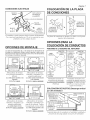
OPCIONES DE MONTAJE
Las tuercas hexagonales de 1Ax 20 aseguran las abrazaderas de
montaje en el alojamiento. Afloje y vuelva a apretar o quite y reem-
place las tuercas segOn sea necesario para colocar las abrazaderas
de montaje en la posici6n deseada.
11/8"
(28,6 mm
F_,brica Max.
descargaderecha _
pordelventilador
I'_' 22" (55,9 cm)=_
' 'h
'_ .... lY2" a
eaunca I1 2v2"
descarqaderechaF'(3818
_16_3.5'mn
° IPll
I_ 18"(45,7cm)-_l
Abrazaderas de montaje
en la posicidn ajustada en
,/cfbrica.
(La salida quedaparalelaalas
viguetas)
(Estructura nueva)
Abrazaderas de montaje
volteadas y montadas ala
armazdn additional.
(La salidaqueda perpendicular
a lasviguetas)
(Estructura nuevao existente)
18" (45,7 cm).,_
F6,brica
1_ descarqaderechaI_
prodelventilador
I_,--22"(55,9cm)-_4
Abrazaderas de montaje
volteadas y montadas ala
armazc'm additional.
(Lasalida _ngulo recto.)
(Estructura nuevao existente.)
Abrazaderas de montaje
volteadas y montadas ala
tapa de la cubierta. Cubier-
ta asegurada con los cables.
(La salida quedaparalelaalas
viguetas)
(Estructura nuevao existente)
COLOCACION DE LA
DE CONEXIONES
P_gina 7
PLACA
CONEXION
HORIZONTAL
DEL CABLE DE
ALIMENTACION
CONEXION
VERTICAL DEL
CABLE DE ALI-
MENTACION
I
La placa de conexiones se monta alos lados o en la parte
superior del alojamiento.
OPCIONES PARA LA
COLOCACION DE CONDUCTOS
POSICIONESDELADESCARGADELVENTILADOR
CONECTOR
PANEL DELCONDUCTO
MOVIBLE__
CONECTOR
DEL
CONDUCTO
(entrada)
El alojamien-
to rotadoy el
panel mow
ible cubre la
caraabierta
anterior.
CONECTOR
DEL
CONDUCTO
(entrada)
Ventilador mostrado en
la posicidn de descarga
derecho pot del ventilador.
(Fcfbrica)
CONECTOR
DEL CONDUCTO
(salida)
PANEL
MOVIBLE
(cambieaesta
Iocalizaci6n)
TRANSICION8"X 12"
(20,3X30,5cm)A
REDONDODE10"
(25,4)(MACHO)_
TRANSICION8"X 12"
20,3X 30,5cm)A REDONDO
DE10"(25,4)(HEMBRA)
CONDUCTO I
qEDONDODE
10"(25.4cm)
(entrada)
VENTILACIONENEL
ALERO CONDUCTO
REDONDODE
10"(25.4 cm)
(salida)
Conexidn tipica de los conductos al ventilador cambiado a
posicidn de descarga c_ngulo recto pot del ventilador.
COLOCACI(SN DE DUCTOS (Descarga vertical
pot del ventilador)
Ventilador mostrado en la
position de c_ngulo recto del
ventilador. (Cambie el panel
movible ala nueva posicidn,
seg{m lo mostrado.)

USO YCUIDADO
Siga las instrucciones para las conexiones el_ctricas que vienen
empacadas con el campana, y observe todos los c6digos locales
y estatales y el C6digo EI6ctrico Nacional.
_ADVERTENCIA: Para reducir el riesgo de sufrir una
descarga el_ctrica, antes de dar servicio al ventilador
descon_ctelo del suministro el_ctrico.
PIEZAS DE SERVlCIO
CLAVE N°.
1
2
3
4
5
6
7
8
9
10
11
12
13
14
15
16
17
18
19
2O
21
22
23
24
25
+
26
27
28
29
30
PIEZA N°.
97014853
99150415
98009520
97014784
97014728
99150591
97006142
99150471
98005512
99420470
98009531
93150487
98005513
99400035
97014788
99260477
99200202
97014785
99080490
99080491
93260447
98009516
99020286
98009514
99150417
98009513
97016794
97016795
98009532
99150472
97016791
99610015
99610028
DESCRIPCION
Solapa del regulador
Tornillo, #8B x 1A*(se req. 16)
Conjunto del regulador (se req. 2)
Conjunto del alojamiento
Abrazadera de montaje (se req. 2)
Tornillo de montaje, #10-12 x .625 (se req. 41
Arn6s de alambre
Tornillo de conexi6n a tierra, #10-32 x 1/2"
(se req. 2)
Placa de conexiones
Tuerca del panel de acceso (se req. 4)
Panel de cubierta movible
Tornillo, #10-24 x .375* (se req. 8)
Cubierta de la caja de conexiones
Buje de alivio de tensi6n
Abrazadera del motor
Tuerca, 1A-20" (se req.11)
Tornillo, 1A-20 x 1/2"(5 req.)
Conjunto del caracol
Motor (HLB9)
Motor (HLB11)
Tuerca, Hex Flange 5/16-18" (se req. 5)
Abrazadera del soporte
Rueda del ventilador (Incluye clave N-°.22)
Anillo de entrada
Tornillo, #8-18 x 1A* (se req. 5)
Abrazadera de soporte del caracol
Conjunto del ventilador, completo (HLB9)
(Incluye art. clave N-°.15-26)
Conjunto del ventilador, completo (HLB11)
(Incluye art. clave N-°.15-26)
Panel de acceso
Tornillo del panel de acceso (se req. 4)
Kit de suspender
Transici6n, 20,3 x 30,5 a 25,4 cm redondo
(8 x 12 a 10 po redondo) (macho)
Transici6n, 20,3 x 30,5 a 25,4 cm redondo
(8 x 12 a 10 po redondo) (hembra)
Pida las piezas de repuesto por N-°.DE PIEZA, no por N-°.DE CLAVE
* Herraje est_.ndar, se puede comprar Iocalmente.
+ No mostrado ensamblado.
GARANTIA
P4gina 8
Para limpiar el conjunto del ventiJador: Quite el panel de ac-
ceso, desconecte el ventilador del alojamiento, quite las tuercas
de montaje del ventilador y cuidadosamente saque el ventilador
del alojamiento. Use el aditamento apropiado de la aspiradora o
un paso suave y jab6n o detergente suave para limpiar el area
de descarga y la rueda del ventilador. NO PERMITA QUE ENTRE
AGUAAL MOTOR. AsegOrese de que el conjunto del ventilador est6
completamente seco antes de volverlo a instalar.
El motor esta permanentemente lubricado. No lubrique ni desmonte
el motor. 29
\
2
/
3
2
9
ii _ 30
14
4
/
\12
11 23
18
CONJUNTO DEL
VENTILADOR
GARANTIABROAN-NUTONELIMITADAPORUN ANO
Broan-NuTonegarantizaal consumidor comprador originalde susproductos quedichos productoscarecer_nde defectosen materialeso enmanode obraper un periodode un a_oa partirde lafecha originalde
compra. NOEXISTENOTRASGARANTIAS,EXPLICITAS0 IMPLICITAS,INCLUYENDO,PERONOLIMITADASA, GARANTIASIMPLICITASDECOMERCIALIZACION0 APTITUDPARAUNPROPOSITOPARTICULAR.
Duranteel periodode ullafio, y asu propio criterio, Broan-NuTonereparardo reemplazarA,sin costoalguno cualquierproducto o piezaqueseencuentredefectuosabajocondiciones normalesdeservicio y uso.
LAPRESENTEGA,RANTIANOCUBRELOSTUBOSFLUORESCENTESNI SUSARRANCADORES,BOMBILLASDEHALOGENOEINCANDESCENTES,FUSIBLES,FILTROS,CONDUCTOS,TAPONESDETECHO0
PAREDESY DEMASACCESORIOSPARACONDUCTOS.Estagarantia no cubre(a) mantenimientoyservicio normales o(b) cualquier producto o piezasquehayansidoutilizadasdeforma err6nea,negligente,
que hayancausadoun accidente,o quehayanside reparadaso mantenidasinapropiadamente(por otrascornpahiasque no seanBroan-NuTone),instalaci6ndefectuosa,o instalaci6ncontraria alas instruc-
clones de instalaci6nrecomendadas.
La duraci6nde cualquier garantia implicita se limita a un periodo de un abecomo se especificaen la garantiaexpresa. Algunos estadosno permiten limitacionesen cuanto al tiempo de expiraci6n de una
garantia implicit& por Io que la limitaciOnantes mencionadapuedeno aplicarse austed.
LAOBLIGACIONDEBROAN-NUTONEDEREPARAR0 REEMPLAZAR,SIGUIENDOELCRITERIODEBROAN-NUTONE,DEBERASERELUNICOYEXCLUSIVORECURSOLEGALDELCOMPRADORBAJOESTA
GARANTIA.BROAN-NUTONENOSERARESPONSABLEPORDANOSINCIDENTALES,CONSIGUIENTES,0 PORDANOSESPECIALESQUESURJANA RAIZDELUSO0 DESEMPENODELPRODUCTO.Algunos
estadosno permiten la exclusi6n o limitaci6n de dahos incidentaleso consiguientes,por Ioque la limitaciOnantes mencionadapuedeno aplicarsea usted.
Estagarantiale proporciona derechoslegales especificos,y usted puedetambi6n tener otros derechos,los cualesvariande estado aestado. Estagarantia reemplazatodas las garantiasanteriores.
Paracalificaren la garantiade servicio, usted debe(a) notificar a Broan-NuToneal domicilio o al nQmerode teldono que semencionaabajo, (b)dar el ndmerodel modelo y la identificaci6nde la pieza,y (c)
describir la naturalezade cualquierdefecto en el producto o pieza.Enel momento desolicitar servicio cubierto por la garantia,usted debede presentarevidenciade la fecha originalde compra.
Broan-NuToneLLC, 926 W. StateStreet, Hartford,Wisconsin 53027 www.broan.com 800-558-1711
Broan-NuToneCanada,Inc., 1140 Tristar Drive,Mississauga, OntarioL5T 1H9 www.broan.ca 877-896-1119
99043702E

ETHL
LATE LI6 E
PourusageavecBroanBite et NuTonePremierhottesde cuissine.
Page 9
POUR USAGE DOMESTIQUE SEULEMENT
AVERTISSEME.T
POURR_DUIRELE RISQUED'iNCENDIE,DE CHOC_LECTRiQUEOU DE
BLESSURESPERSONNELLES,OBSERVEZCEQUI SUIT:
1. Utilisezcette unit_ seulement de la faqon pr@ue par le fabricant. Pour
d'aut resrenseignements,contactezlefabricantb,I'adresseouaunum@o
de t_l@hone qui se trouve dartsla garantie.
2. Avant d'effectuer uner@aration ouun entretien sur cetappareil,coupez
lecourantautableaud'alimentation etverrouillez celui-ci pour emp#,cher
que la tension soit remise accidentellement. Lorsque le verrouillage
de la d@onnexion n'est pas possible, mettez bien en vue un signal
d'avertissement telle qu'une _tiquette,sur le panneaud'alimentation.
3. L'installation et la posedes ills _lectriques doivent #,treeffectu@s par
une ou des personnes qualifi@s conform_ment b,tousles codes et
normesapplicables, incluant lesnormes deconstruction en rapport aux
incendies.
4. II faut suffisamment d'air pour une combustion appropri_e et
I'@happement des gaz par le tuyau de la chemin_e de I'@uipement
br_lant du combustible pour pr@enir un contre-courant. Suivez les
instructions du fabricant de I'@uipement de chauffage et les normes
de s@urit6 telles que celles publi@s par la National FireProtection As-
sociation (NFPA)et I'American Society for Heating, Refrigeration and
Air Conditioning Engineers(ASHRAE)et desautorit_s du code local.
5. Lorsdelacoupeoudu perqagedans unmurou unplafond,prenezsoinde
nepasendommagerlesfils 61ectriqueset les autres utilit_s dissimul@s.
6. Lad_chargedes ventilateurs b,conduit parI'@ent doit toujours sefaire
b,I'ext@ieur.
7. Pour r6duire le rsque d'incendie, utilisez seulement des donduits de
ventilation en m_tal.
8. Si cette unit_ dolt #,treinstall@ au-dessus d'une baignoire ou d'une
douche, elledolt 6tremarqu@comme 6tantappropri@ pour I'application
et#,treconnect@b,un circuit d6riv6prot6ge GFCI(interrupteur decircuit
en casde ddaut de mise &laterre du neutre).
9. Neplacezjamais un interrupteur dans un endroit oQil peut 6tre rejoint
d'une baignoire ou d'une douche.
10. Cette unit_ doit 6tre mise b,laterre.
AFINDEDIIVlINUERLESRISQUESD'INCENDIEPOUVANTSEDItCLENCHER
SURLASURFACEDECUISSON:
1. Nejamais laisser sans surveillance des unit_s de surface r_gl_esb,feu
vif. Enplus deg_n@erdelafum@, lesd_bordementsdegraissepeuvent
prendrefeu. Chauffer les huiles lentementb,feu doux ou moyen.
2. Toujours mettre en marche la hotte durant la cuisson b,feu vif ou la
cuisson d'aliments b.fiamber.
3. Nettoyer r_guli_rement les ventilateurs d'a@ation. On ne dolt tol@er
aucune accumulation degraisse sur le ventilateur ou sur lefiltre.
4. Utiliser une casserole de grosseur appropri@. Toujours utiliser une
batteriede cuisine proportionnelle b.I'_l_ment de surface.
AFIN DEDIMINUERLESRISQUESDE BLESSURESPOUVANTSURVENIR
LORSQU'UNFEUSEDECLENCNESURLASURFACEDECUiSSON,SUiVEZ
CESDiRECTiVES:
1. ETOUFFEZLESFLAMMESavecun couvercle herm6tique, unet61eb,bis-
cuits ouun plateauen m_talpuis_teignezlacuisini_re. PRENEZGARDE
AUXBRULURES.Sivous neparvenezpasb,_teindreimm_diatementles
flammes, EVACUEZLES LIEUXET CONTACTEZVOTREPOSTELOCAL
DELUTTECONTRELES INCENDIES.
2. NEVOUSEMPAREZJAMAIS D'UN PLATQUIS'ESTENFLAMME-Vous
risqueriezde vous brQler.
AVERTISSEMENT
3. N'UTILISEZJAMAISD'EAU,incluant leslinges b,vaissellesou serviettes
mouill_s car celapeut provoquer uneviolente explosion devapeur.
4. Utilisez un extincteur SEULEMENTsk
A. IIs'agit d'un extincteur de classeABCet que vous savez
comment vous en servir.
B. IIs'agit d'un petit feu qui ne sepropage pasailleurs que sur
la cuisini_re.
C.Vousavezappel_votre poste local de lutte contre les incendies.
D.Vous pouvezcombattre lefeu tout en ayant ac@sb,unesortie.
* Bas_sur "Kitchen FireSafetyTips" _dit_ parNFPA.
ATTENTION
1. Pour ventilation g_n@aleseulement. NeI'utilisez pas pour @acuer les
vapeursou mat@iauxdangereuxou que peuventexploser.
2. Pour @iter d'endommager les coussinets du moteur et des turbines
bruyantes et/oumal @uilibr@s, assurezque I'unit6 motrice estexempte
de poussi_re provenantdes murs en pierres@ches et la construction.
3. Si leventiJateutest install_dartsunendtoit non conditionn_(teJqu'un
grenier): Entourez leventilateur d'un isolant thermique afin de r_duire
toute condensation@entuelle.
4. Veuillez lire I'_tiquette de sp@ifications sur le produit pour d'autres
renseignements et exigences.
TABLE DES MATll RES
Cemanuel se divisecomme suit :
* INSTALLATIONTYPIQUE
Cette section montre une installation standard dans un bb,timent en
cours de construction ou d_jb,construit.
- Montage (construction en cours)
-Montage (construction termin@)
-Montage (kit pour accrocher)
- installation desconduits (d@harge horizontale de ventilateur)
- Cb,blage
*OPTIONSDEMONTAGE
* POSiTiONDELA PLAQUEDECABLAGE
*OPTIONSD'INSTALLATiONDESCONDUITS
- Positions de la d_chargede lasouffierie
- Installation desconduits (d@harge vertical deventilateur)
* UTILISATIONETENTRETIEN
* PIi:CESDERECHANGE
* GARANTiE
Installateur: Remetez ce manuel au
protpri taire de maison.
Propri taire de maison: Mode
d'utilisation et soin ala page 12.

iNSTALLATiON TYPIQUE
MONTAGE (Construction en cours)
CONDUIT CIRCULAIRE DE 10 po (25,4 cm) (sortie)
TRANSITION DE 8x 12 po au
10 po circulaire (20,3 x 30,5 cm
/au 25,4 cm circulaire) (m&le)
/ /
TRANSITION DE
8 x 12 po au
10 po circulaire
(20,3 x 30,5 cm
_C au 25,4 cm
circulaire)
(femelle)
CONDUIT
IRCULAIRE DE
10 po (25,4 cm)
(prise)
/
ECROU DE GRILLE
(Installez sur les
trous cartes dans le
Iogement.) _ @
Soufflerie preas-
semblee en position
de decharge de
soufflerie
dans ligne
VlS DE
PANNEAU
DACCESS
SUPPORTS I
SOLIVE DE
PLAFOND
(24po/61cm
centre)
PANN EAU DRCCESS
Appareil installd dans un bc_timent en cours de construction.
MONTAG E (construction termin_e)
TRANSiTiON DE 8 x 12 po au
10 po circulaire (20,3 x 30,5 cm
au 25,4 cm circulaire) (femelle)
TRANSITION DE 8 x 12 po au
10 po circulaire (20,3 x 30,5 cm
au 25,4 cm circulaire) (mbJe)
CONDUIT CIRCULAIRE
DE 10 po (25,4 cm) (prise)
SUPPORTS
preassembl6s
pour plafonds
SOLIVE DE
PLAFOND
(24 po /61 cm
centre)
SUPPORTS
DE 10 po
(25,4 cm)
(sortie)
Soufflerie preassembl6e
en position de decharge de
soufflerie droit angle.
ECROU DE
GRILLE
VlS DE [_ (Installez sur
PANNEAU /;_ les trous car-
DACCESS res dans le
Iogement.)
Appareil installd dans un bc_timent ddi& construit.
iMPORTANT: Retirez la bande d'exp#dition de I'amortisseur.
Veiller & retirer le ruban adh_sif d'exp_dition du volet du registre et
s'assurer que ce dernier s'ouvre et se ferme librement b,I'int6rieur
du conduit. Utiliser du ruban adh6sif pour assurer et 6tancher les
raccords des conduits.
Page 10
INSTALLATION TYPIQUE
MONTAGE EN UTIUSANT LE KIT DE CINTRE
(inclus)
TRANSITIONDE VlS ET
8 x 12 po au RONDELLEDE
10 po circulaire LE KITPOUR
(20,3 x 30,5 cm ACCROCHER
25,4 cm circulaire):
(femelle) RESSORTDE
PROLONGATION
CONDUIT
CHAiNE CIRCULAIREDE
DELE KIT 10po (25,4 cm)
POUR (ADMISSION)
ACCROCHER
BOULOND'OEIL
DELE KITPOUR
ACCROCHER
TRANSITIONDE
8x 12 poau lOpo
circulaire (20,3 x
30,5 cm au25,4
cm circulaire)
(m_le)
VlS ET
RONDELLEDE
POUR
ACCROCHER
SUPPORTS
I ECROUDE
..----- PANNEAUD'ACCESS
, (Installez sur les
_ I trous carr_s dans le
CIRCULAIREDE
10 po (25,4 cm)
(SORTIE)
n,^rrEee _ _1 _ VlS DE PANNEAU
PANNEAUu _uuEoo "_ _ 11- D'ACCESS
5bz!/jqerie p,'dassemblde en position de ddcharge clans ligne.
INSTALLATION DES CONDUITS (d_charge
horizontale de ventilateur)
CONDUIT_ CHAPEAU DE TOIT
CIRCULAIRE CONDUIT ClRCU-
DE LAIRE DE
10 po TRANSITION 10 po
(25,4 cm) CIRCULAIRE (25,4 cm)
8 x 12 po (20,3 x
30,5 cm) AU
10 po (.25.4 cm)
(MALE)
TRANSITION CIRCULAIRE
8x 12po
(20,3 x 30,5 cm) AU
10 po (25.4 cm) (FEMELLE)
COUDE
CIRCULAIRE DE
10 po (25.4 cm)
tCHAPEAU
DEMUR
Deux maniS,'es de ,'accorded" les conduits _un appareil
prdmontd.

_B sSUS/
RIERE DU
OmER
FIL DE TERRE A
PLAQUE DE C_,BLAGE
BLANC
AU
BLANC
PLAQUE
DE
CAB LAGE
ENTREE
"_ 12o VCA
(du le hotte)
Le ventilateur peut Otre branchd depuis 1'extdrieur du
bo#ier. Utiliser des connecteurs homologu_s UL pour les
branchements, co11/brm_ment aux codes locaux en vigueur.
OPTIONS DE MONTAGE
Des 6crous &six pans 1A-20fixent les supports au boftier. Desserrer
et resserrer ou retirer et replacer les 6crous si n6cessaire, selon la
position d6sir6e pour le support.
D_charg#_
desouffierie
dans
..... pr6sassembl_e_
22 pc
(55,9 cm)
11/8pc
(28,6 ram)
Max.
-=,4 f
I0 0 111/2au
'= D_char_ 21/2
de souffierie po
dansIjA@_ (38,1 a
pr_sassemN_e 63.5 ram)
18po ___J
(45,7 cm)
Supports en position prdas-
semblde
(Sortie parall_le aux solives)
(B&timent en cours de con-
struction)
Supports retournds et fixds
un cadre suppldmentaire.
(Sortie perpendiculaire aux
solives)
(Construction neuve ou ex-
istante)
POSITION
C.,&.BLAGE DE LA Page 11
PLAQUE DE
BRANCHEMENT DU
CABLE DALIMENTATION
,_ I'HORIZONTALE
BRANCHEMENT
DUCABLE
DALIMENTATION
I I ,_LA VERTICALE
La plaque de c_blage se fixe sur le cdtd ou sur le dessus du
bo#ier.
OPTIONS D'INSTALLATION
DES CONDUITS
POSITIONSDELADi_CHARGEDELASOUFFLERIE
PANNEAU
AMOVIBLE CONNECTEUR
DU CONDUIT
CONNECTEUR DU
CONDUIT
(prise)
eo
Ventilateur illustrd
en position de
ddchar_e de sou[_
darts ligne. (Prdassembld)
Le panneau CONNECTEUR
tourn_et pan- DU CONDUIT
neauamovibl (sortie)
couvre le c6t_
ouvert pr_c6-
dent.
PANNEAU
AMOVIBLE (&
placer ici)
CONNECTEUR
DU CONDUIT (prise)
Ventilateur illustrd en
position de ddchal_e de sou[--
fterie droit angle. (Changer la
position du panneau amovible
tel qu 'illustrd.)
18po
(45,7 cm)
D_charg#_
de souffierie
dans
pr6sassembl_e _
22 pc
(55,9 cm)
Supports retournds et fixds b
un cadre suppldmentaire.
(Sortie droit angle.)
(Construction neuve ou ex-
istante_)
Supports retournds etfixds
en haut du bo#ier. Bo#ier
su_pendu par des cobbles.
(Sortie parall_le aux solives)
(Construction neuve ou ex-
istante)
INSTALLATION DES CONDUITS (decharge
vertical de ventilateur)
TRANSITIONCIRCULAIRE
8x 12pc (20,3x 30,5cm)
10pc (25.4cm)(MALE)\
TRANSITIONCIRCULAIRE
8x12po
(20,3x30,5cm) AU
10pc (25.4cm) \
(FEMELLE) \
OONDUlT
CIRCULAIRE
DE10pc
(25.4cm)
CHAPEAUDETOIT
CONDUIT
CIRCULAIRE
DE10 po
(25.4 cm)
Raccordement de conduit typique bun ventilateu/_ converti
en ddchal_e ve,'_ticale

UTILISATION ET ENTRETIEN
Suivre les instructions de c&blage fournies avec le hotte et respecter
tous les codes Iocaux et provinciaux en vigueur, de meme que le
Code national de 1'61ectricit6.
_AVERTISSEMENT : Pour diminuer les risques
de d6charge 6iectrique, d_brancher la source
d'alimentation avant toute operation d'entretien.
Pll CES DE RECHANGE
LC:GENDE
1
2
3
4
5
6
7
8
9
10
11
12
13
14
15
16
17
18
19
20
21
22
23
24
25
+
26
27
28
29
30
N° DE REE
97014853
99150415
98009520
97014784
97014728
99150591
97006142
99150471
98005512
99420470
98009531
93150487
98005513
99400035
97014788
99260477
99200202
97014785
99080490
99080491
93260447
98009516
99020286
98009514
99150417
98009513
97016794
97016795
98009532
99150472
97016791
99610015
99610028
DESCRiPTiON
Clapet
Vis, #8B x 1A*(16 oblig.)
Registre (2 oblig.)
Boftier
Support (2 oblig.)
Vis, #10-12 x .625 (4 oblig.)
Harnais & fi[s
Vis de terre, 10-32 x 1/2"(2 oblig.)
plaque de c&blage
Ecrou de panneau d'access (4 oblig.)
Panneau amovible du boitier
Vis, #10-24 x .375* (8 oblig.)
Couvercle de la bofte de c&blage
R6ducteur de tension
Support de moteur
Ecrou, 1A-20" (11 oblig.)
Vis, 1A-20 x 1/2"(5 oblig.)
Volute
Moteur (HLB9)
Moteur (HLB11)
I_crou hexagonal & collerette 5/16-18"
(5 oblig.)
Support
Roue de soufflerie (inclut n° 16gende 22)
Bague d'arrJv6e
Vis, #8-18 x 1A*(5 oblig.)
Support de volute
Soufflerie, ensemble (HLB9)
(inclut n° [6gende 15 & 26)
Souffierie, ensemble (HLB11)
(inclut n° 16gende 15 & 26)
Panneau de access
Vis de fixation de panneau de access
(4 oblig.)
Kit de accrocher
Transition de 8 x 12 pc au 10pc circulaire
(20,3 x 30,5 cm au 25,4 cm circulaire) (m&le)
Transition de 8 x 12 pc au 10pc circulaire
(20,3 x 30,5 cm au 25,4 cm circulaire) (femelle)
Commander les pi_ces de rechange par num6ro de r6f6rence et non
9.I'aide du num6ro de 16gende.
* VisserJe standard - peut 6tre achet6e Iocalement.
+ Non montr6 assembl6.
GARANTIE
Page 12
Pour nettoyer la soufflerie : Retirer la panneau d'access, de-
brancher la soufflerie du boitier, retirer les 6crous de fixation de
la soufflerie et retirer delicatement la soufflerie du boitier. Utiliser
un accessoire d'aspirateur appropri6 ou retirer la grille et nettoyer
& I'aide d'un chiffon doux et de savon ou de detergent doux pour
nettoyer la zone de decharge de la soufflerie et la roue. NE PAS
LAISSER D'EAU S'[NFILTRER DANS LE MOTEUR. S'assurer que
la soufflerie est compl_tement s_che avant de la reinstaller.
Le moteur est lubrifi6 en permanence. Ne pas lubrifier ou d6monter
le moteur. 29
\
1 _ _ 30
2
/
28\
\ 14
13 J18
4
/
11
19 _'_ 16
20 "_ 17 zzz ._
........................................ _% 26
ENSEMBLE DE
SOUFFLERIE
GARANTIELIMITEEDEUNAN DEBROAN-NUTONE
Broan-NuTonegarantit&I'acheteurconspmmateur original de ses produits qu'ils sont exem.pts de vice de materiauxou de fabrication po.urune perioded'un an &compter de la date d'achatoriginal. IL N'Y
APASD'AUTRESGARANTIES,EXPRIMEESOU IMPLICITES,INCLUANTMAIS NONLIMITEESAUXGARANTIESIMPLICITESDEQUALITEMARCHANDEETDECONVENANCEDANSUN BUTPARTICULIER.
Durantcette perioded'un an, Broan-NuTone,&sadiscretion, r@areraou reinpl.aceragratuitement tout produit ou piecequis'avereraddectueux et ayant eteutilisenormalementetd'une manierenonabusive.
CETTEGARANTIENES'APPLIQUEPASAUXTUBESFLUORESCENTSETAUXDEMARREURS,NIAUXAMPOULESHALOGENESOUINCANDESCENTES,FUSIBLES,FILTRES,CONDUITS,CAPUCHONSDETOIT,
CAPUCHONSMURAUX ETAUTRESACCESSOIRESPOURCONDUITS.Cettegarantiene couvre pas (a) I'entretienet le servicenormalou (b)tout produit ou pieceendommage&la suite d'un mauvaisusage,
d'unenegligence,d'un accident,d'un entretieninadequatou d'unereparation (autreque par Broan-NuTone),d'une mauvaiseinstallation oud'une installationnonconformeau moded'installation recommande.
La duree de toute garantie implicite est limitee _ uneperiode de un an tel que specific pour la garantie exprimee. CertainsEtats ou provinces ne permettent pas de limitation de la duree d'une garantie
implicite. Cettecondition nes'applique.donc peut-Strepa.sdansvotre cas.
L'ENGAGEMENTDE BROAN-NUTONEA REPAREROUA REMPLACER,AU CH.OIXDE BROAN-NUTONE,SERA LA SEULEOBLIGATIONEXCLUSIVESOUSCETTEGARANTIE. BROAN-NUTONENESE
T.IENDRAPASRESPONSABLEDESDOMMAGESDIRECTS,INDIRECTSOUSPECIAUXAYANTUN LIENDIRECTOUINDIRECTAVECL'UTILISATIONOU LAPERFORMANCEDESESPRODUITS.Certains
Etatsou provinces ne permettent pas I'exclusion ou la limitation de dommagesdirects ou indirects. Cettecondition ne s'applique donc.peut-etre pas dansvotre cas.
Cettegarantievous donne des droits specifiqueset il sepeut que vous ayezd'autresdroits qui varientd'une province _ I'autre ou d'un Etat_ I'autre. Cettegarantieannule toutes les garanties precedentes.
Pour le servicesous garantie,vous devez (a) aviser Broan-NuTone_ I'adresseou numerode telephonementionneeci-dessous, (b) donner le numero de modele etI'identification de la pieceet (c) decrire la
naturede tout defaut dans le produit ou la piece. Au moment de la demande de servicesous garantie,vous devezpresenterune preuve de ladate d'achat originaldu produit en question.
Broan-NuToneLLC,926 W.StateStreet, Hartford, Wisconsin 53027 www.broan.com 800-558-1711
Broan-NuToneCanada,Inc., 1140Tristar Drive,Mississauga, Ontario L5T 1H9 www.broan.ca 877-896-1119
99043702E
-
 1
1
-
 2
2
-
 3
3
-
 4
4
-
 5
5
-
 6
6
-
 7
7
-
 8
8
-
 9
9
-
 10
10
-
 11
11
-
 12
12


Broan HLB11 El manual del propietario
- Tipo
- El manual del propietario
- Este manual también es adecuado para
en otros idiomas
- français: Broan HLB11 Le manuel du propriétaire