Blaupunkt RVC 4.1 KH El manual del propietario
- Tipo
- El manual del propietario
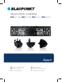
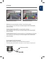
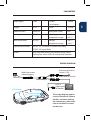
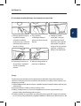
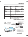
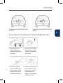
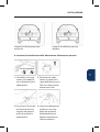
El Blaupunkt RVC 4.1 KH es una cámara de visión trasera que se puede montar en la superficie o en un soporte, con una resolución de 688x528 píxeles y una impermeabilidad de grado IP67.
Con un consumo de corriente inferior a 40 mA y una potencia menor a 0,35 W, es compatible con la mayoría de los vehículos con una salida de 12 V CC.
La cámara cuenta con la función de visión nocturna con una iluminación mínima de 0,1 lux, lo que permite una visibilidad clara incluso en condiciones de poca luz.
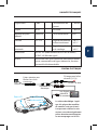
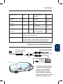
Además, se puede complementar con un cable extensor RCA de 10 metros (VK-RVC 4.
El Blaupunkt RVC 4.1 KH es una cámara de visión trasera que se puede montar en la superficie o en un soporte, con una resolución de 688x528 píxeles y una impermeabilidad de grado IP67.
Con un consumo de corriente inferior a 40 mA y una potencia menor a 0,35 W, es compatible con la mayoría de los vehículos con una salida de 12 V CC.
La cámara cuenta con la función de visión nocturna con una iluminación mínima de 0,1 lux, lo que permite una visibilidad clara incluso en condiciones de poca luz.
Además, se puede complementar con un cable extensor RCA de 10 metros (VK-RVC 4.


-
 1
1
-
 2
2
-
 3
3
-
 4
4
-
 5
5
-
 6
6
-
 7
7
-
 8
8
-
 9
9
-
 10
10
-
 11
11
-
 12
12
-
 13
13
-
 14
14
-
 15
15
-
 16
16
-
 17
17
-
 18
18
-
 19
19
-
 20
20
-
 21
21
-
 22
22
-
 23
23
-
 24
24
-
 25
25
-
 26
26
-
 27
27
-
 28
28
-
 29
29
-
 30
30
-
 31
31
-
 32
32


Blaupunkt RVC 4.1 KH El manual del propietario
- Tipo
- El manual del propietario
El Blaupunkt RVC 4.1 KH es una cámara de visión trasera que se puede montar en la superficie o en un soporte, con una resolución de 688x528 píxeles y una impermeabilidad de grado IP67.
Con un consumo de corriente inferior a 40 mA y una potencia menor a 0,35 W, es compatible con la mayoría de los vehículos con una salida de 12 V CC.
La cámara cuenta con la función de visión nocturna con una iluminación mínima de 0,1 lux, lo que permite una visibilidad clara incluso en condiciones de poca luz.
Además, se puede complementar con un cable extensor RCA de 10 metros (VK-RVC 4.
En otros idiomas
Otros documentos
-
Valeo park vision 632211 Manual de usuario
-
Dometic PerfectView CAM360 Instrucciones de operación
-
-
BMW Advanced Car Eye 2.0 Instructions For Use Manual
-
Garmin Drahtlose Ruckfahrkamera BC20 Guía de instalación
-
-
 Manual de BC 20 Manual de usuario
-
Dometic CAM360AHD Manual de usuario
-
Alpine INE-W INE-W611D Guía de instalación
