Craftsman 358.796270 El manual del propietario
- Categoría
- Podadoras de césped
- Tipo
- El manual del propietario
Este manual también es adecuado para

Operator's Manual
®
CRAFTSMAN
24cc/1.46 cu.in. 2-Cycle
17 Inch Cutting Path
GASOLINE WEEDWAOKER ®
Model No.
358.796270
WARNING:
Read and follow all Safety Rules and Operating
Instructions before first use of this product.
t_ For answers to your questions about this product:
Call 7 am-7 pm, Mon-Sat; Sun, 10 am-7 pm
• 1-800-235-5878
Sears, Roebuck and Co., Hoffman Estates, IL 60179 USA
530088523 3/t 5/00
/
g
0
/
0
g

Warranty Statement 2 Storage 11
Safety Rules 2 Troubleshooting Chart 12
Assembly 4 Emissions Statement 12
Operation 5 Repair Parts List 14
Maintenance 8 Spanish 17
Service & Adjustments 9 Parts and Ordering Back Cover
FULL ONE YEAR WARRANTY ON CRAFTSMAN GAS POWERED
WEEDWACKER ® LINE TRIMMER
For one year from the date of purchase, when this Craftsman Gas Powered
WeedwackeKR: Line Trimmer is maintained, lubricated, and tuned up according to
the operating and maintenance instructions in the Operator's Manual, Sears will
repair, free of charge, any defect in materials or workmanship.
This warranty excludes nylon line, spark plug, and air filter, which are expendable
parts and become worn during normal use.
If this WeedwackerrR; Line Trimmer is used for commercial purposes, this warran-
ty applies for only 90 days from the date of purchase. If this WeedwackeK_ Line
Trimmer is used for rental purposes, this warranty applies for only 30 days from
the date of purchase. This warranty applies only while this product is in use in the
United States.
WARRANTY SERVICE ISAVAILABLE BY RETURNING THE WEEDWACKERrR; LINE
TRIMMER TO THE NEAREST SEARS SERVICE CENTER IN THE UNITED STATES.
This warranty gives you specific legal rights, and you may also have other rights
which vary from state to state.
Sears, Roebuck and Co., D/817 WA Hoffman Estates, IL 60179
_WARNING: When using garden-
ing appliances, basic safety precau-
tions must always be followed to re-
duce the risk of fire and serious injury.
Read and follow all instructions.
This power unit can be dangerous!
Operator is responsible for following
instructions and warnings on unit and
in manual. Read entire Operator's
Manual before using unit! Be thor-
oughly familiar with the controls and
the proper use of the unit. Restrict the
use of this unit to persons who have
read, understand, and will follow the
instructions and warnings on the unit
and in the manual. Never allow chil-
dren to operate this unit.
_Y INFORMATION
ON THE UNIT
A
dl_ DANGER: Never use blades or
flailing devices. This unit is designed
for line trimmer use only. Use of any
other accessories or attachments will
increase the risk of injury.
@0©
_,WARNING: Trimmer line throws
objects violently. You and others can
be blinded/injured. Wear eye and leg
protection. Keep body parts clear of
rotating line. Keep children, bystand-
ers, and animals 50 feet (15 m) away.
If approached, stop unit immediately.
Eye Protection
\

• If situations occur which are not cov-
ered in this manual, use care and
good judgement. If you need assis-
tance, contact your Sears Service
Center or call 1-800-235-5878.
OPERATOR SAFETY
• Always wear safety eye protection.
• Always wear long pants, long
sleeves, boots, and gloves. Wearing
safety leg guards is recommended.
Do not go barefoot or wear sandals.
Stay clear of spinning line.
• Secure hair above shoulder length.
Secure or remove loose clothing or
clothing with loosely hanging ties,
straps, tassels, etc. They can be
caught in moving parts.
• Do not operate when you are tired,
ill, or under the influence of alcohol,
drugs, or medication.
• Wear hearing protection if you use
unit for more than 1-1/2 hours per
day.
• Never start or run inside a closed
room or building. Breathing exhaust
fumes can kill.
• Keep handles free of oil and fuel.
UNIT / MAINTENANCE SAFETY
• Disconnect the spark plug before
performing maintenance except car-
buretor adjustments.
• Look for and replace damaged or
loose parts before each use. Look
for and repair fuel leaks before use.
Keep in good working condition.
• Replace trimmer head parts that are
chipped, cracked, broken, or dam-
aged in any other way before using
the unit.
• Make sure unit is assembled cor-
rectly as shown in this manual.
• Make carburetor adjustments with
lower end supported to prevent line
from contacting any object.
• Keep others away when making car-
buretor adjustments.
• Use only recommended Craftsman
accessories and replacement parts.
FUEL SAFETY
• Mix and pour fuel outdoors.
• Keep away from sparks or flames.
• Use a container approved for fuel.
• Do not smoke or allow smoking near
fuel or the unit.
• Wipe up all fuel spills.
• Move at least 10 feet (3 meters)
away from fueling site before start-
ing engine.
• Stop engine and allow to cool before
removing fuel cap.
CUTTING SAFETY
• Use only for trimming, mowing, edg-
ing, and sweeping. Do not use for
pruning or hedge trimming.
• Inspect the area before each use.
Remove objects (rocks, broken
glass, nails, wire, etc.) which can be
thrown by or become entangled in
line. Hard objects can damage the
trimmer head and be thrown causing
serious injury.
• Keep firm footing and balance. Do
not overreach.
• Keep all parts of your body away
from muffler and spinning line. Keep
engine below waist level. A hot muf-
fler can cause serious burns.
• Cutting on left side of the shield will
throw debris away from the operator.
TRANSPORTING AND STORAGE
• Allow engine to cool; secure unit be-
fore storing or transporting in ve-
hicle.
• Empty the fuel tank before storing or
transporting the unit. Use up fuel left
in the carburetor by starting the en-
gine and letting it run until it stops.
• Store unit and fuel in area where
fuel vapors cannot reach sparks or
open flames from water heaters,
electric motors or switches, fur-
Races, etc.
• Store unit so line limiter cannot acci-
dentally cause injury. The unit can
be hung by the tube.
• Store unit out of reach of children.
• If situations occur which are not cov-
ered in this manual, use care and
good judgment. If you need assis-
tance, call 1-800-235-5878.
SPECIAL NOTICE: This unit is not
equipped with a temperature limiting
muffler and spark arresting screen
which meets the requirements of Cali-
fornia Codes 4442 and 4443. All U.S.
forest land and the states of California,
Idaho, Maine, Minnesota, New Jersey,
Oregon, and Washington require by
law that many internal combustion en-
gines be equipped with a spark arres-

tarscreen.Ifyouoperateinalocale
wheresuchregulationsexist,youare
legallyresponsibleforinstallingand
maintainingtheoperatingconditionof
theseparts.Failuretodosoisaviola-
tionofthelaw.ContactyourSears
ServiceCenterforthecorrectparts.
SPECIALNOTICE:Exposureto
vibrationsthroughprolongeduseof
gasolinepoweredhandtoolscould
causebloodvesselornervedamage
inthefingers,hands,andjointsof
peoplepronetocirculationdisorders
orabnormalswellings.Prolongeduse
incoldweatherhasbeenlinkedto
bloodvesseldamageinotherwise
healthypeople.Ifsymptomsoccur
suchasnumbness,pain,lossof
strength,changeinskincolorortex-
ture,orlossoffeelinginthefingers,
hands,orjoints,discontinuetheuseof
thistoolandseekmedicalattention.
Ananti-vibrationsystemdoesnot
guaranteetheavoidanceofthese
problems.Userswhooperatepower
toolsonacontinualandregularbasis
mustmonitorcloselytheirphysical
conditionandtheconditionofthistool.
CARTONCONTENTS
Checkcartoncontentsagainstthefol-
lowinglist.
Model358.796270
• Trimmer
• Shieldwithwingnut
• AssistHandlewithboltandknob
• Containerofoil
• Replacementspool
Examinepartsfordamage.Donot
usedamagedparts.
NOTE:Ifyouneedassistanceorfind
partsmissingordamaged,call
1-800-235-5878.
Itisnormalforthefuelfiltertorattlein
theempty fuel tank.
Finding fuel or oil residue on muffler is
normal due to carburetor adjustments
and testing done by the manufacturer.
ASSEMBLY
,_WARNING: If received as-
sembled, repeat all steps to ensure
your unit is properly assembled and all
fasteners are secure.
Be sure to assemble the handle to the
unit before you assemble the shield.
ATTACHING THE HANDLE
(some units are already assembled)
Groove /
• Assemble handle to the unit as
shown; make sure bottom of handle
is seated in the groove in the trigger
housing.
NOTE: Knob must be assembled on
the right hand side of the unit as
shown in the illustration.
• Make sure the bolt is seated into the
hex-shaped hole in the handle.
• Pivot handle to a comfortable posi-
tion.
• Tighten handle securely.
ATTACHING SHIELD
_ WARNING: The shield must be
properly installed. The shield provides
partial protection from the risk of thrown
objects to the operator and others and
is equipped with a line limiter which cuts
excess line to the proper length. The
line limiter (on underside of shield) is
sharp and can cut you. For proper
orientation, see illustration in OPERA-
TION section.

• Removewingnutfromshield.
• Insertbracketintoslotasshown.
• Pivotshielduntilboltpassesthrough
holeinbracket.
• Securelytightenwingnutontobolt.
Slot
Shield "_\/
_ _._F--_"__,)")Bracket
" _) Wing
_ nut
KNOW YOUR TRIMMER
READ THIS OPERATOR'S MANUAL AND SAFETY RULES BEFORE OPERATING YOUR
UNIT. Compare the illustrations with your unit to familiarize yourself with the location
of the various controls and adjustments. Save this manual for future reference.
b_ Assist Handle
Tube
Muffler
Engine Stop \ Throttle Trimmer
Switch Trigger Edge
Spark Plug Guide
Starter
Rope _ Choke
Lever Shield
Primer
Bulb
Fuel Mix
Fill Cap
ENGINE STOP SWITCH
Tile engine STOP switch is used to stop
the engine. Push and hold the engine
stop switch in the STOP or OFF posi-
tion until the engine has fully stopped.
PRIMER BULB
The PRIMER BULB removes air from
the carburetor and fuel lines and fills
them with fuel. This allows you to start
the engine with fewer pulls on the
starter rope. Activate the primer bulb
by pressing it and allowing it to return
to its original form.
Line
Limiter
Blade
CHOKE
The CHOKE helps to supply fuel to the
engine to aid in cold starting. Activate
the choke by moving the choke lever
to the FULL CHOKE position. After en-
gine attempts to start, move the choke
lever to the HALF CHOKE position.
Once engine starts, move choke lever
to the OFF CHOKE position.
EDGE GUIDE
The EDGE GUIDE protects the unit
from contacting the ground during
edging.
BEFORE STARTING ENGINE
_WARNING: Be sure to read the
fuel information in the safety rules
before you begin. Ifyou do not
understand the safety rules, do not
attempt to fuel your unit. Call
1-800-235-5878.
FUELING ENGINE
This engine is certified to operate on
unleaded gasoline. Before operation,
gasoline must be mixed with a good
quality 2-cycle air-cooled engine oil.
We recommend Craftsman brand oil.
Mix gasoline and oil at a ratio of 40:1
(A 40:1 ratio is obtained by mixing 3.2
5

ouncesofoilwith1gallonofunleaded
gasoline).DONOTUSEautomotiveoil
orboatoil.Theseoilswillcause
enginedamage.Whenmixingfuel,
followinstructionsprintedon
container.
Onceoilisaddedtogasoline,shake
containermomentarilytoassurethat
thefuelisthoroughlymixed.Always
readandfollowthesafetyrules
relatingtofuelbeforefuelingyourunit.
IMPORTANT
Experienceindicatesthatalcohol
blendedfuels(calledgasoholorusing
ethanolormethanol)canattractmois-
turewhichleadstoseparationand
formationofacidsduringstorage.
Acidicgascandamagethefuelsys-
temofanenginewhileinstorage.
Toavoidengineproblems,emptyfuel
systembeforestoragefor30daysor
longer.Draingastank,startengineand
letitrununtilfuellinesandcarburetor
areempty.Usefreshfuelnextseason.
Neveruseengineorcarburetorcleaner
productsinthefueltankorpermanent
damagemayoccur.SeetheSTORAGE
sectionforadditionalinformation.
HOW TO STOP YOUR UNIT
Push and hold tile engine stop switch
in the STOP or OFF position until the
unit has fully stopped.
STARTING YOUR ENGINE
Choke Lever
Engine
Stop
Switch _
p,
HOW TO START YOUR UNIT
WARNING: The trimmer head will turn
while starting the engine. A hot muffler
can cause serious burns.
COLD ENGINE STARTING OR
STARTING AFTER REFUELING
• Set unit on a flat surface.
STARTING _
POSITION
• Slowly press primer bulb 6 times.
• Move choke lever to FULL CHOKE-
position.
Choke Lever
Primer Bulb \i_J_''_'l_// Muffler
• Squeeze the throttle trigger fully and
hold through all remaining steps.
• Pull starter rope handle sharply 6
times.
NOTE: If the engine sounds as if it is
trying to start before the 6th pull, go to
the next step.
• Move choke lever to HALF CHOKE
position.
• Pull starter rope sharply until engine
runs, but no more than 6 pulls.
NOTE: If the engine has not started
after 6 pulls (at HALF CHOKE), check
to make sure the choke lever is in the
proper position. Then, move the
choke lever to the FULL CHOKE posi-
tion and press the primer bulb 6 times;
squeeze and hold the throttle trigger
and pull the starter rope 2 more times.
Move the choke lever to HALF CHOKE
and pull the starter rope until the en-
gine runs, but no more than 6 more
pulls. If the engine still has not started,
it is probably flooded. Proceed to
STARTING A FLOODED ENGINE.
• Allow the engine to run 10 seconds,
then move the choke lever to OFF
CHOKE. Allow the unit to run for 30
more seconds at OFF CHOKE before
releasing the throttle trigger.
RESTARTING A WARM ENGINE
• Move the choke lever to the HALF
CHOKE position.
• Squeeze and hold the throttle trig-
ger. Keep throttle trigger fully
squeezed until the engine runs
smoothly.
• Pull starter rope sharply until engine
runs, but no more than 5 pulls.
• Allow engine to run 15 seconds,
then move the choke lever to OFF
CHOKE.
NOTE: If engine has not started, pull
starter rope 5 more pulls. If engine still
does not run, it is probably flooded=
6

DIFFICULT STARTING OR
STARTING A FLOODED ENGINE
Flooded engines can be started by
placing the choke lever in the OFF
CHOKE position; then, pull the rope to
clear the engine of excess fuel. This
could require pulling the starter handle
many times depending on how badly
the unit is flooded.
If the unit still doesn't start, refer to
TROUBLESHO©TING CHART or call
1-800-235-5878.
OPERATING INSTRUCTIONS
OPERATING POSITION
ALWAYS WEAR:
Eye Protection
Lonc
Heav
Cut from your rightto your left.
Do not run the engine at a higher speed
than necessary. The cutting line will cut
efficiently when the engine is run at less
than full throttle. At lower speeds, there
is less engine noise and vibration. The
cutting line will last longer and will be
less likely to "weld" onto the spool.
Always release the throttle trigger and
allow the engine to return to idle
speed when not cutting.
To stop engine:
• Release the throttle trigger.
• Push and hold the engine stop
switch in the STOP or OFF position
until the unit has fully stopped.
TWIST AND EDGE
• Pull the tab toward ttle engine.
• Twist the tube to the edging position;
release tab.
TRIMMER LINE ADVANCE
The cutting head advances line auto-
matically. Do not tap head on the
ground to advance line. This may
break parts and cause cutting head to
malfunction.
Upon unit start up, the line will advance
automatically to the correct cutting path
length.
Always keep the shield in place when
the tool is being operated.
411WARNING: Use only .080" (2
mm) diameter round line. Other
sizes and shapes of line will not ad-
vance properly and will result in im-
proper cutting head function or can
cause serious injury. Do not use other
materials such as wire, string, rope,
etc. Wire can break off during cutting
and become a dangerous missile that
can cause serious injury.
CUTTING METHODS
_kWARNING: Use minimum speed
and do not crowd the line when cutting
around hard objects (rock, gravel, fence
posts, etc.), which can damage the trim-
mer head, become entangled in the
line, or be thrown causing a serious
hazard.
• The tip of the line does the cutting.
You will achieve the best performance
and minimum line wear by not crowd-
ing the line into cutting area. The right
and wrong ways are shown in the fol-
lowing illustration.
Tip of the Line Line Crowded Into
Does The Cutting Work Area
Night Wrong
• The line will easily remove grass
and weeds from around walls,
fences, trees and flower beds, but it
also can cut the tender bark of trees
or shrubs and scar fences.
• For trimming or scalping, use less
than full throttle to increase line life
and decrease head wear, especially:
• During light duty cutting.
• Near objects around which the line
can wrap such as small posts,
trees or fence wire.
• For mowing or sweeping, use full
throttle for a good clean job.
7

A
41 WARNING: Always wear eye
protection. Never lean over the trim-
mer head, Rocks or debris can rico-
chet or be thrown into eyes and face
and cause blindness or other serious
injury.
TRIMMING - Hold the bottom of the
trimmer head about 3 in. (8 cm) above
the ground and at an angle. Allow only
the tip of the line to make contact. Do
not force trimmer line into work area.
Trimming __ 1t
AboveGrJon
SCALPING - The scalping technique
removes unwanted vegetation. Hold
the bottom of the trimmer head about
3 in. (8 cm) above the ground and at
an angle. Allow the tip of the line to
strike the ground around trees, posts,
monuments, etc. This technique in-
creases line wear.
Scalping
MOWING - Your trimmer is ideal for
mowing in places conventional lawn
mowers cannot reach. In the mowing
position, keep the line parallel to the
ground. Avoid pressing the head into
the ground as this can scalp the
ground and damage the tool.
cow,no))
SWEEPING - The fanning action of
rotating line can be used for a quick
and easy clean up. Keep line parallel
to and above the surfaces being
swept and move the tool from side to
side.
Sweeping_ .....
EDGING - The Twist and Edge fea-
ture allows for easy edging of side-
walks, patios, driveways, etc. Adjust
trimmer to the edging position. Allow
only the tip of the line to make contact.
Do not force trimmer line into work
3 in. (8 ore) area.
Above Ground
Edging _,_
_,_;_,:_;_7..-_ _..
MAINTENANCE SCHEDULE
CARE & MAINTENANCE TASK WHEN TO PERFORM
Check for Loose fasteners and parts Before each use
Check for damaged or worn parts Before each use
Clean unit and labels After each use
Clean air filter Every 5 hours of operation
Replace spark plug Yearly

GENERAL RECOMMEN DATIONS
The warranty on this unit does not
cover items that have been subjected
to operator abuse or negligence. To
receive full value from the warranty,
the operator must maintain unit as
instructed in this manual. Various ad-
justments will need to be made peri-
odically to properly maintain your unit.
CHECK FOR LOOSE
FASTENERS AND PARTS
• Spark Plug Boot
• Air Filter
• Housing Screws
• Assist Handle Screws
• Shield Screw
CHECK FOR DAMAGED OR
WORN PARTS
Refer replacement of damaged/worn
parts to your Sears Service Center.
• Engine STOP Switch - Ensure
switch functions properly by press-
ing and holding the switch in the
STOP position. Make sure engine
stops; then restart engine and con-
tinue.
• Fuel Tank - Do not use unit if fuel
tank shows signs of damage or leaks.
• Shield - Discontinue use of unit if
debris shield is damaged.
CLEAN UNIT & LABELS
• Clean the unit using a damp cloth
with a mild detergent.
• Wipe off unit with a clean dry cloth.
CLEAN AIR FILTER
A dirty air filter decreases engine per-
formance and increases fuel con-
sumption and harmful emissions. Al-
ways clean after every 5 hours of
operation.
• Clean the cover and the area
around it to keep dirt and debris
from falling into the carburetor
chamber when the cover is
removed.
• Remove parts as illustrated.
NOTE: Do not clean filter in gasoline
or other flammable solvent to avoid
creating a fire hazard or producing
harmful evaporative emissions.
• Wash the filter in soap and water.
• Allow filter to dry.
• Replace parts.
f_. ,_Filter
_/_ -4_,_ Screws
REPLACE SPARK PLUG
Replace the spark plug each year to
ensure the engine starts easier and
runs better. Set spark plug gap at
0.025 in. Ignition timing is fixed and
nonadjustable.
• Twist, then pull off spark plug boot.
• Remove spark plug from cylinder
and discard.
• Replace with Champion RCJ-8Y
spark plug and tighten with a 3/4 in.
socket wrench (10-12 ft.-Ibs).
• Reinstall the spark plug boot.
LINE REPLACEMENT
Pre-wound spools offer the most con-
venient method for replacing line and
ensuring optimum performance.
• Replacement spools are color-
coded to ensure use of the correct
spool with your unit. Be sure to use
the same color spool as the existing
spool.
NOTE: Always clear dirt and debris
from cutting head components when
performing any type of maintenance.
• Hold spool and unscrew cap by turn-
ing in the direction shown on top of
the cap.
• Remove line guide ring and spool.
NOTE: When removing and/or instal-
ling spool, ensure dust cup remains
installed over shaft.
Dust Spool Lin_e Cap
Shaft ciP ,.,_'q_,_, r,ng jf
Use a pre-wound spool or refill spool
with line. If using a pre-wound spool,
remove tape strip from line and spool.
9

REFILLING THE SPOOL WITH LINE
_WARNING: Use only .080" (2
mm) diameter round line. Other
sizes and shapes of line will not ad-
vance properly and will result in im-
proper cutting head function or can
cause serious injury. Do not use other
materials such as wire, string, rope,
etc. Wire can break off during cutting
and become a dangerous missile that
can cause serious injury.
• Cut a length of 30 feet of .080" (2
ram) diameter round Craftsman
brand line=
Spool
• Insert one end of line into center cav-
ity of empty spool. Ensure line will
feed into spool in the direction shown
on the spool (counterclockwise).
• Continue feeding line into spool,
leaving 4 - 6 inches (10 - 15 cm)
unwound from center of spool.
INSTALLING SPOOL WITH LINE
• Install replacement spool.
• Thread line through line guide ring.
CARBURETOR ADJUSTMENT
_L WARNING: The trimmer head
will be spinning during most of this
procedure. Wear your protective
equipment and observe all safety pre-
cautions. After making mixture adjust-
ments, recheck idle speed.
Carburetor adjustment is critical and if
done improperly can permanently
damage the engine as well as the car-
buretor. If you require further assis-
tance or are unsure about performing
this procedure, call 1-800-235-5878.
Old fuel, a dirty air filter, a dirty fuel fil-
ter, or flooding may give the impres-
sion of an improperly adjusted carbu-
retor. Check these conditions before
adjusting the carburetor.
The carburetor has been carefully set
at the factory. Adjustments may be
necessary if you notice any of the fol-
lowing conditions:
• Engine will not idle, See IDLE SPEED
under adjusting procedure.
• Engine dies or hesitates instead of
accelerating. See ACCELERATION
CHECK under adjusting procedure.
• Loss of cutting power. See MIXTURE
ADJUSTMENT under adjusting
procedure.
There are two adjustment screws on
the carburetor. They are located in the
area just above the primer bulb.
Mixture Screw (with
Limiter Cap)
Idle
3peed
Screw
Linethrough guide ring
ff
Replacement Spool
• Rest guide ring on spool and place
line in slot. Allow line to extend 4 -
6 inches (10 - 15 cm) from center of
spool.
• Ensure line remains in slot while
screwing cap on to the shaft. Only
tighten cap hand tightt
Air Filter
Cover
CARBURETOR PRESETS
When making carburetor preset adjust-
ments, do not force plastic limiter caps
beyond stops or damage will occur.
If carburetor presets are not needed,
proceed to ADJUSTING PROCEDURE,
IDLE SPEED.
To adiust presets:
• Turn mixture screw counterclock-
wise until it stops.
• Turn the idle speed screw clockwise
until it stops. Now turn counterclock-
wise 4-1/2 turns.
10

• Startengine,cutgrassfor3
minutes,andproceedtothe
adjustmentsection.Ifenginedoes
notstart,
refertoTROUBLESHOOTINGCHART
orcall1-800-235-5878.
• Ifengineperformanceisacceptable
atthepresetpositions,nofurther
adjustmentisnecessary.
ADJUSTING PROCEDURE
Idle Speed
Allow engine to idle. Adjust speed until
engine runs without stalling.
• Turn clockwise to increase engine
speed if engine stalls or dies.
• Turn counterclockwise to decrease
speed.
No further adjustments are necessary
if performance is satisfactory.
Mixture Adjustment "H"
DO NOT operate engine at full throttle
for prolonged periods while making
adjustments. Damage to the engine
can occur. Ensure line is fully ex-
tended.
Based on performance while cutting,
turn the mixture adjustment in
1/16-turn increments as follows:
• Clockwise until the engine has good
power while cutting with no hesita-
tion.
Do not adjust by sound or speed,
but judge by how well the engine
performs while cutting.
• Counterclockwise if the engine has
speed but dies or lacks power while
cutting.
After completing adjustments, check
for acceleration. Reset if necessary.
Acceleration Check
If engine dies or hesitates instead of
accelerating, turn mixture adjustment
counterclockwise until you have
smooth acceleration. Recheck and
adjust as necessary for acceptable
performance.
Prepare unit for storage at end of sea-
son or if it will not be used for 30 days
or more.
_WARNING:
• Allow engine to cool, and secure the
unit before storing or transporting.
• Store unit and fuel in a well venti-
lated area where fuel vapors cannot
reach sparks or open flames from
water heaters, electric motors or
switches, furnaces, etc.
• Store unit with all guards in place.
Position unit so that any sharp ob-
ject cannot accidentally cause injury.
• Store unit and fuel well out of the
reach of children.
EXTERNAL SURFACES
If your unit is to be stored for a period
of time, clean it thoroughly before stor-
age. Store in a clean dry area.
• Lightly oil external metal surfaces.
FUEL SYSTEM
Under FUELING ENGINE in the OPERA-
TION section of this manual, see mes-
sage labeled IMPORTANT regarding
the use of gasohol in your engine.
Fuel stabilizer is an acceptable alter-
native in minimizing the formation of
fuel gum deposits during storage. Add
stabilizer to the gasoline in the fuel
tank or fuel storage container. Follow
the mix instructions found on stabilizer
container. Run engine at least 5 min-
utes after adding stabilizer.
Craftsman 40:1,2-cycle engine oil (air
cooled) is already blended with fuel
stabilizer. If you do not use this Sears
oil, you can add a fuel stabilizer to
your fuel tank.
ENGINE
• Remove spark plug and pour 1 tea-
spoon of 40:1,2-cycle engine oil (air
cooled) through the spark plug
opening. Slowly pull the starter rope
8 to 10 times to distribute oil.
• Replace spark plug with new one of
recommended type and heat range.
• Clean air filter.
• Check entire unit for loose screws,
nuts, and bolts. Replace any dam-
aged, broken, or worn parts.
• At the beginning of the next season,
use only fresh fuel having the proper
gasoline to oil ratio.
OTHER
• Do not store gasoline from one sea-
son to another.
• Replace gasoline can if it starts to
rust.
11

TROUBLESHOOTING CHART
TROUBLE CAUSE
Engine will not • Engine flooded.
start. • Fuel tank empty.
• Spark plug not firing.
• Fuel not reaching
carburetor.
• Compression low.
Engine will not • Idle speed set too low=
idle properly.
Engine will not
accelerate,
lacks power,
or dies under
a load.
Engine smokes
excessively.
Engine runs hot.
• Idle speed set too high.
• Carburetor requires
adjustment.
• Crankshaft seals worn.
• Compression low.
• Air filter dirty.
• Spark plug fouled.
• Carburetor requires
adjustment.
• Carbon build up.
• Compression low.
• Choke partially on.
• Fuel mixture incorrect.
• Air filter dirty.
• Carburetor requires
adjustment.
• Fuel mixture incorrect.
• Spark plug incorrect.
• Carburetor requires
adjustment
• Carbon build up=
REMEDY
• See "Starting Instructions."
• Fill tank with correct fuel mixture.
• Install new spark plug.
• Check for dirty fuel filter; replace.
Check for kinked or split fuel line;
repair or replace.
• Contact Sears Service.
• Adjust idle speed screw
clockwise to increase speed.
• Adjust idle speed screw counter-
clockwise to reduce speed.
• See "Carburetor Adjustments."
• Contact Sears Service.
• Contact Sears Service.
• Clean or replace air filter.
• Clean or replace spark plug
and re-gap.
• See "Carburetor Adjustments."
• Contact Sears Service.
• Contact Sears Service.
• Adjust choke.
• Empty fuel tank and refill with
correct fuel mixture.
• Clean or replace air filter.
• See "Carburetor Adjustments."
• See "Fueling Your Unit."
• Replace with correct spark plug.
• See "Carburetor Adjustments."
• Contact Sears Service.
YOUR WARRANTY RIGHTS AND
OBLIGATIONS: The U.S. Environ-
mental Protection Agency and SEARS
ROEBUCK AND CO. USA are
pleased to explain the emissions con-
trol system warranty on your lawn and
garden equipment engine. All new util-
ity and lawn and garden equipment
engines must be designed, built, and
equipped to meet the stringent anti-
smog standards. SEARS must war-
rant the emission control system on
your lawn and garden equipment en-
gine for the periods of time listed be-
low provided there has been no
abuse, neglect, or improper mainte-
nance of your lawn and garden equip-
ment engine. Your emission control
system includes parts such as the car-
buretor and the ignition system.
Where a warrantable condition exits,
SEARS will repair your lawn and gar-
den equipment engine at no cost to
you. Expenses covered under warran-
ty include diagnosis, parts and labor.
MANUFACTURER'S WARRANTY
COVERAGE: If any emissions related
part on your engine (as listed under
Emissions Control Warranty Parts
List) is defective or a defect in the ma-
terials or workmanship of the engine
causes the failure of such an emission
related part, the part will be repaired or
replaced by SEARS. OWNER'S
12

WARRANTY RESPONSIBILITIES:
As the lawn and garden equipment
engine owner, you are responsible for
the performance of the required main-
tenance listed in your Owner's Manu-
al. SEARS recommends that you re-
tain all receipts covering maintenance
on your lawn and garden equipment
engine, but SEARS cannot deny war-
ranty solely for the lack of receipts or
for your failure to ensure the perfor-
mance of all scheduled maintenance.
As the lawn and garden equipment
engine owner, you should be aware
that SEARS may deny you warranty
coverage if your lawn and garden
equipment engine or a part of it has
failed due to abuse, neglect, improper
maintenance, unapproved modifica-
tions, or the use of parts not made or
approved by the original equipment
manufacturer. You are responsible for
presenting your lawn and garden
equipment engine to a SEARS autho-
rized repair center as soon as a prob-
lem exists. Warranty repairs should be
completed in a reasonable amount of
time, not to exceed 30 days. If you
have any questions regarding your
warranty rights and responsibilities,
you should contact your nearest au-
thorized service center or call SEARS
at 1-800-473-7247 WARRANTY
COMMENCEMENT DATE: The war-
ranty period begins on the date the
lawn and garden equipment engine is
purchased. LENGTH OF COVER-
AGE: This warranty shall be for a peri-
od of two years from the initial date of
purchase. WHAT IS COVERED: RE-
PAIR OR REPLACEMENT OF
PARTS. Repair or replacement of any
warranted part will be performed at no
charge to the owner at an approved
SEARS servicing center. If you have
any questions regarding your warranty
rights and responsibilities, you should
contact your nearest authorized ser-
vice center or call SEARS at
1-800-473-7247. WARRANTY PE-
RIOD: Any warranted part which is not
scheduled for replacement as re-
quired maintenance, or which is
scheduled only for regular inspection
to the effect of "repair or replace as
necessary" shall be warranted for 2
years. Any warranted part which is
scheduled for replacement as re-
quired maintenance shall be war-
ranted for the period of time up to the
first scheduled replacement point for
that part. DIAGNOSIS: The owner
shall not be charged for diagnostic la-
bor which leads to the determination
that a warranted part is defective if the
diagnostic work is performed at an ap-
proved SEARS servicing center. CON-
SEQUENTIAL DAMAGES: SEARS
may be liable for damages to other
engine components caused by the
failure of a warranted part still under
warranty. WHAT IS NOT COVERED:
All failures caused by abuse, neglect,
or improper maintenance are not cov-
ered. ADD-ON OR MODIFIED
PARTS: The use of add-on or modified
parts can be grounds for disallowing a
warranty claim. SEARS is not liable to
cover failures of warranted parts
caused by the use of add-on or modi-
fied parts. ROW TO FILE A CLAIM: If
you have any questions regarding
your warranty rights and responsibili-
ties, you should contact your nearest
authorized service center or call
SEARS at 1-800-473-7247. WHERE
TO GET WARRANTY SERVICE: War-
ranty services or repairs shall be pro-
vided at all SEARS service centers, call:
1-800-473-7247. MAINTENANCE, RE-
PLACEMENT AND REPAIR OF EMIS-
SION RELATED PARTS: Any SEARS
approved replacement part used in
the performance of any warranty
maintenance or repair on emission re-
lated parts will be provided without
charge to the owner if the part is under
warranty. EMISSION CONTROL
WARRANTY PARTS LIST: Carbure-
tor, Ignition System: Spark Plug (cov-
ered up to maintenance schedule),
Ignition Module. MAINTENANCE
STATEMENT: The owner is responsi-
ble for the performance of all required
maintenance as defined in the own-
er's manual.
13

Declaraci6n de Garantia 17 AImacenaje 27
Reglas de Seguridad 17 Tabla Diagn6stica 29
Montaje 19 Declaraci6n de Garantia 30
Uso 20 Lista de Piezas 14
Mantenimiento 24 Piezas de Repuesto
Servicie y Ajustes 25 y Encomiendad Contratapa
GARANTIA DE UN AI_IO COMPLETO PARA LA CORTADORA DE LINEA A GA-
SOLINA WEEDWACKER ® DE CRAFTSMAN ®
Durante un a_io, a partir de la fecha de compra, siempre que se haga el manten-
imiento, la lubricaci6n y los ajustes a esta Cortadora de Linea a Gasolina
Weedwacker de Craftsman segOn las instrucciones de uso y mantenimiento en el
Manual del Usuario, Sears reparar5 cualquier defecto de materiales o de mano
de obra gratuitamente.
Esta garantia excluye la linea de nil6n, la bujia y el filtro de aire, que son piezas
fungibles que se gastan con el uso normal.
Si se usa esta Cortadora de linea Weedwacker de Craftsman para fines comer-
ciales, esta garantia tendr& validez por s61a 90 dias a partir de la fecha de com-
pra. Si se usa esta Cortandor de linea Weedwacker de Craftsman para fines de
alquiler, esta garantia tendr& validez per s61a 30 dias a partir de la fecha de com-
pra. Esta garantia tendr_t validez Qnicamente mientras se use este producto den-
tro de los Estados Unidos.
SE OBTENDRA SERVlCIO BAJO GARANTIA DEVOLVlENDO LACORTADORA DE LINEA
WEEDWACKER AL CENTRO DE SERVICIO SEARS MAS CERCANO EN LOS ESTADOS
UNIDOS.
Esta garantia confiere derechos legales especificos al propietario, que tal vez
tenga asimismo otros derechos que vanan entre estados.
Sears, Roebuck and Co., D/817 WA Hoffman Estates, IL 60179
ADVERTENCIA: AI usar cualqui-
er herramienta de fuerza de jardineria,
deber&n observarse precauciones b&si-
cas de seguirdad en todo memento para
reducir el riesgo de incendio y graves her-
idas. Lea y cumpla con todas las instruc-
ciones.
iEsta herramienta de fuerza puede ser
peligrosa! Cabe al usuario le responsa-
bilidad de cumplir con todas las adver-
tencias e instrucciones, iLea el Manual
del Usuario en su totalidad antes de
usar el aparato! Est6 completamente
familiarizado con los controles y con el
uso correcto del aparato. Limite el uso
de este aparato a aquellas personas
que hayan leido y comprendido, y que
vayan a obedecer, todas las adverten-
cias e instrucciones tanto en el aparato
como en el manual. No permita nuncaa
los nffios que usen este aparato.
DEL APARATO
'_ PELIGRO: Nunca use cuchillas ni
dispositivos desgranadores. El aparato
fue dise_iado para set usado exclusiva-
mente come cortador a linea. El uso de
cualquier otra pieza o accesorio incre-
mentar& el peligro de heridas. Este apa-
rato ha sido diseSado exclusivamente
como cortador a linea.
Q©O
_' ADVERTEN ClA: La linea de corte
arroja objetos violentamente. Ustes, al
igual que otras personas, puede quedar
ciego o herido. Use anteojos de seguri-
dad y protecci6n en las piemas. Manten-
17

gatodaslaspartesdelcuerpoalejadas
delalineagirante.
Mantengaalosni_os,losespectadoresy
animalesaunadistanciaminimade15
metros(50pies).Pareelmotorinmedia-
tamentesialguienseleacerca.
Useanteojosdeseguridad
Siacontecealgunasituaci6nno
previstaenestemanual,tengacuidado
yusebuencriterio.Sinecesitaayuda,
entreencontactoconsuCentrode
ServicioSearsoIlameal
1-800-235-5878.
SEGURIDAD DEL USUARIO
• Use siempre protecci6n de ojos.
• Use siempre pantalones largos,
mangas largas, botas y guantes. Se
recomienda el use de pantorrilleras
de seguridad. No use el aparato
descalzo, ni con sandalias. Si ester
completamente tapado, estate, m_.s
protegido de los escombros y peda-
zos de plantas t6xicas arrojados per
la linea girante. Mant6ngase alejado
de la finea girante.
• Mantenga el cabello per encima de
los hombros, at_tndolo para tal efecto
si es necesario. No use ropa suelta ni
ropa con corbatas, tiras, borlas, etc.
que cuelgan libremente. Pueden en-
redarse en las piezas en movimiento.
• No haga use del aparato estando
cansado, enfermo, ansioso o bajo la
influencia del alcohol, de drogas o de
remedios.
• Use protecci6n de o6dos si usa el
aparato pot m_ts de una hora y me-
dia per dia.
• Nunca ponga el aparato en marcha
ni Io deje en marcha dentro de un
recinto cerrado. Respirar los va-
pores del combustible Io puede ma-
tar.
• Mantenga las manijas libres de
aceite y de combustible.
SEGU RIDAD DEL APARATO Y EN EL
MANTENIMIENTO
• Desconecte la bujia antes de hacer
cualquier mantenimiento menos los
ajustes al carburador.
• Inspeccione el aparato y cambie las
piezas daSadas o flojas antes de
cada uso. Repare toda fuga de com-
bustible antes de usar el aparato.
Mantenga el aparato en buenas
condiciones de use.
• Cambie todas las piezas del cabe-
zal que est6n descantilladas, res-
quebrajadas, quebradas o da_iadas
de cualquier otro modo, antes de
usar el aparato.
• AsegOrese que el aparato est6 cor-
rectamente armado como se mues-
tra en el manual.
• Haga los ajustes al carburador con
el cabezal apoyado de mode que la
linea no pueda tocar nada.
• Mantenga alejadas alas dem_.s per-
sonas siempre que haga ajustes al
carbu rador.
• Use exclusivamente los accesorios y
repuestos Craftsman recomendados.
SEGURIDAD CON EL COMBUSTIBLE
• Mezcle y vierta el combustible al
aire fibre.
• Mantengalo alejado de las chispas y
de las llamas.
• Use recipiente aprobado para el
combustible.
• No fume ni permita que se fume cer-
ca del combustible ni del aparato ni
mientras 6ste este en use.
• Limpie todo el combustible derrama-
do.
• Alejese a per Io menos 3 metros (10
pies) del lugar de abastecimiento
antes de poner en marcha el motor.
• Pare el motor y permita que se
enfrie el aparato antes de retirar la
tapa del tanque.
SEGURIDAD AL CORTAR
• Use el aparato exclusivamente para
recortar, para cortar c6sped, para cor-
tar bordes y para barrer. No Io use
para podar ni para recortar seto.
• Inspeccione el _trea antes de cada
use. Retire los objetos (piedras, vidrio
roto, clavos, alambre, etc.) que se
puedan enredar en la linea o que
6sta pueda arrojar. Los objetos duros
pueden daSar el cabezal y 6ste los
puede arrojar, causando graves heri-
das.
• Inspeccione el _.rea a ser cortada
antes de cada use. Retire los obje-
tos (piedras, vidrio rote, clavos,
alambre, hilo, etc.) que se puedan
enredar en el cabezal o que 6ste
pueda arrojar.
• Mantenga el equilibrio, con los pies
en una superficie estable. No se ex-
tienda demasiado.
• Mantenga todas las partes del cuer-
po alejadas de la linea girante y del
silenciador. Mantenga el motor por
debajo del nivel de la cintura. El si-
18

lenciadorpuedecausargravesque-
madurascuandoest&caliente.
• Sisecortaconlalineadelladoiz-
quierdodelprotector,losescombros
volar&nensentidoopuestoalusuario.
TRANSPORTE Y ALMACENAMIENTO
• Espere que el motor se enfrie y fije
bien el aparato antes de quardarlo o
de transportarlo en un vehiculo.
• Vacie el tanque de combustible antes
de guardar el aparato o de transpor-
tarlo. Consuma todo el combustible
restante en el carburador poniendo el
motor en marcha y dej&ndolo en mar-
cha hasta que le motor se pare solo.
• Guarde el aparato y el combustible
en un lugar donde los vapores del
combustible no puedan alcanzar
chispas ni llamas provenientes de
los termotanques, los motores o in-
terruptores el6ctricos, los calefac-
totes centrales, etc.
• Guarde el aparato de modo que el
cuchilla del limitador de linea no
pueda causar heridas accidentales.
Se puede colgar el aparato por la
caja el eje de propulsi6n.
• Guarde el aparato fuera del alcance
de los niSos.
Si acontece alguna situaci6n no pre-
vista en este manual, tenga cuidado y
use buen criterio. Si necesita ayuda,
Ilame al 1-800-235-5878
AVlSO SPECIAL: Su sierra no viene
equipada con silenciador limitador de
temperatura ni con rejilla antichispa que
cumpla los requisitos de los C6digos de
California 4442 y 4443. Todas las tier-
ras forestadas federales, m#.s los esta-
dos de California, Idaho, Maine, Minne-
sota, Nueva Jersey, Washington y
Oreg6n, requieren por ley que muchos
motores de combusti6n interna est6n
equipados con rejilla antichispa. Si
usted el aparato donde existen tales re-
glamento, usted tiene la responsabili-
dad juridica de instalar y mantener es-
tas piezas en correcto estado de
funcionamiento. De Io contrario, estar&
en infracci6n de la ley.
AVlSO SPECIAL: El estar expuesto a
las vibraciones a trav6s del uso prolon-
gado de herramientas de fuerza a ga-
solina puede cuasar daSos a los vases
sanguineos o a los nervios de los de-
dos, las manos y las coyunturas en
aquellas personas que tienen propensi-
dad a los trastornos de la circulaci6n o
alas hinchazones anormales. El uso
prolongado en tiempo frio ha sido aso-
ciado con daSos a los vasos sna-
guineos de personas que per otra parte
se encuentran en perfecto estado de
salud. Si ocurren sintomas tales como
el entumecimiento, el dolor, la falta de
fuerza, los cambios en el color o la tex-
tura de la piel o falta de sentido en los
dedos, las manos o las coyunturas,
deje de usar esta m&quina inmediata-
mente y procure atenci6n m6dica. Los
sistemas de anti-vibraci6n no garanti-
zan que se eviten tales problemes. Los
usuarios que hacen uso continuo y pro-
Iongando de las herramientas de fuerza
deben fiscalizar atentamente su estado
fisico y el estado del aparato.
CONTENICO DE LA CAJA
Use la siguiente lista para verificar
que todas la piezas hayan sido in-
cluidas:
Modelo 358.796270
• Cortadora
• Cubierta Protectora
• Mango Auxiliar
• Recipiente de Aceite
• Bobina de Repuesto
Examine las piezas para verificar que no
haya da_os. No use piezas da_adas.
AVlSO: Si necesita ayuda, si faltan
piezas o si hay piezas da_adas, Ilame
al nQmero 1-800-235-5878.
Es normal escuchar que el filtro de
combustible golpetee en el tanque
vacio.
Es normal encontrar residuos de aceite
o de gasolina en el silenciador, debido
a los ajustes al carburador y alas prue-
bas efectuadas pot el fabricante.
MONTAJE
_ADVERTENCIA: Si recibi6 el
aparato ya armado, repita todos los
pasos para asegurar que el mismo se
encuentre correctamente armado y
que todos los fijadores se encuentren
bien ajustados.
Asegurese de colocar en el mango en
el aparato antes de armar la cubierta
protectora.
19

COMO INSTALLAR EL MANGO
(algunas unidades vienen con el mango
ya instalado)
• Monte el mango en el aparato como
se ilustra; asegurese que la parte
inferior del mango se encuentre en
la ranura en la cubierta del gatillo.
AVlSO: La perilla de ajuste deber_.
set armada en el lado izquierdo de el
aparato como se muestra en el ilustra-
ci6n.
• Aseg0rese de que el tornillo se en-
cuentre Iocalizado dentro del hueco
en forma de hex_tgonal que se en-
cuentra en el mango.
• Gire el mango hasta Ilegar a la posi-
cion m_.s confortable.
• Aseg0rese de ajustar firmemente el
mango.
INSTALACION DE LA CUBIERTA
PROTECTORA
_ADVERTENCIA: La cubierta pro-
tectora deber_t ser instalada correcta-
mente. Esta cubierta provee protecci6n
parcial contra el riesgo de que objetos
arrojados al aire puedan causar acci-
dentes al usuario y otras personas, y
viene equipada con un limitador de
linea que corta el exceso de line& El
limitador de linea (que se encuentra en
la parte inferior de la cubierta protecto-
ra) es filoso y puede cortar. Para conse-
guir la orientaci6n apropiada vea la ilus-
traci6n que se encuentra en la secci6n
de Uso.
• Remueva la tuerca mariposa de la
cubierta protectora.
• Introduzca el soporte dentro de la
ranura como se muestra.
• Haga girar la cubierta protectora
hasta que el tornillo pase a trav6s
del hueco en el soporte.
• Apriete firmemente la tuerca maripo-
sa en el tornillo.
Cubierta Protectora
Tuerca
Maripos_
CONOZCA SU APARATO
LEA ESTE MANUAL DEL USUARIO Y LAS REGLAS DE SEGURIDAD ANTES DE PONER
ELAPARATO EN MARCHA. Compare las ilustraciones con su aparato para familiad-
zarse con la ubicaci6n de los diversos controles y ajustes. Guarde este manual
para uso futuro.
Mango Auxiliar
Tubo
Silenciador GatiHo
interruptor Acelerador
ON/STOP
Bujia
Mango de la Cubierta
Cuerda de Palaeca del Protectora
Arranque Cebador _
Cabezal Guia
de Corte
para
bordes
Bombeador
Tapa del Tanque Cuchilla del
de Mezcla de Limitador de
Combustible Linea
20

INTERRUPTOR ON/STOP
Se usa el interrupter ON/STOP para de-
tener el motor. Presione y sostenga el
interrputor para detener el motor.
BOMBEADOR
El BOMBEADOR retira el aire de el car-
burador y de las lineas de combus-
tible y las Ilena de mezcla de combus-
tible, permiti6ndole poner el motor en
marcha con menos tirones de la cuer-
da de arranque. Accione el bombea-
dor oprimi6ndolo y luego dejando que
este recobre su forma original.
CEBADOR
El CEBADOR ayuda a suministrar com-
bustible al motor para facilitar el arran-
que cuando el motor est& frio. Acione
el cebador colocando la palanca en la
posici6n FULL CHOKE. Despu6s que el
motor intente arrancar, mueva la pa-
lanca del cebador a la posici6n HALF
CHOKE. Despues que el motor se
haya puesto en marcha, ponga la pa-
lanca del cebador en la posici6n OFF
CHOKE.
GUIA PARA BORDES
La GUiA PARABORDES impedir& que el
aparato toque el suelo durante el proce-
dimiento de bordear.
ANTES DE PONER EN MARCHA EL
MOTOR
_ ADVERTENCIA: Lea
atentamente la informaci6n sobre el
combustible en laas reglas de
seguridad antes de comenzar. Si no
comprende las reglas de seguridad,
no intente abastecer el aparato de
combustible. Llame al nOmero
1-800-235-5878.
ABASTECIMIENTO DEL MOTOR
Este motor est& habilitado para
funcionar con gasolina sin plomo. Antes
de comenzar con el uso, se deber&
mezclar la gasolina con un aceite de
buena calidad para motores de 2
tiempos enfriados a aire.
Recomendamos el aceite de la marca
Craftsman. Mezcle la gasolina con el
aceite en la proporci6n 40:1. (Se
obtiene una proporci6n de 40:1
mezclando 3.2 onzas de aceite con
cada gal6n de gasolina sin plomo). NO
USE aceite para autom6viles ni para
barcas. Estos aceites daSar&n el motor.
AI mezclar el combustible, siga las
instrucciones impresas en el recipiente.
Una vez haya aSadido el aceite a la
gasolina, agite al recipiente brevemente
para asegurar que el combustible este
completamente mezclado. Siempre lea
y siga las instrucciones de seguridad
que tienen que ver con el combustible
antes de abastecer el aparato.
IMPORTANTE
La experiencia indica que los combus-
tible mezclados con alcohol (los Ila-
mados gasohol o los que contienen
etanol o metanol) pueden atraer la hu-
medad, Io que puede causar la sepa-
raci6n y la formaci6n de &cidos du-
rante el almacenaje. La gasolina
&cida puede daSar el sistema de com-
bustible del motor durante el almace-
naje.
Para evitar problemas con el motor,
deber& vaciarse el sistema de com-
bustible antes de almacenar el apara-
to por 30 dias o m&s. Vac[e el tanque
de combustible, ponga el motor en
marcha y d6jelo en marcha hasta que
las lineas de combustible y el carbura-
dor queden vacios. Use combustible
fresco para la pr6xima temporada.
Nunca use productos de limpieza de
motor o carburador en el tanque de
combustible ya que de hacerla puede
provocar daSos permanentes.
Vea la secci6n de ALMACENAJE para
informaci6n adicional.
COMO DETENER EL MOTOR
Presione y sostenga el interruptor ON/
STOP en la posici6n STOP hasta que
la unidad se haya detenido completa-
mente.
Palanca del cebador
Interruptor
ON/STOP
N
COMO PONER EN MARCHA
EL MOTOR
_' ADVERTEN ClA: El cabezal de
corte girar& mientras se este intentan-
do poner en marcha el motor. Evite el
hacer ningOn tipo de contacto con el
silenciador. Un silenciador caliente
podria provocar quemaduras de gra-
vedad si se toca.
21

MOTOR FRIO O CALIENTE DES-
PUES DE QUEDAR SIN COMBUS-
TIBLE
• Ponga la unidad en una superficie
plana.
POSICION DE
• Oprima lentamente el bombeador 6
veces.
• Mueva la palanca del cebador a la
posici6n FULL CHOKE.
Palanca del
Gatillo
Bombeadol
Silenciador
• Apriete y sujete el gatillo durante to-
dos los pasos aiguientea.
• Tire firmemente del mango de la
cuerda de arranque de 6 veces.
AVlSO: Si el motor parece como si
fuera a arrancar antes del sexto tir6n
de la cuerda de arranque, prosiga con
el paso siguiente.
• Mueva la palanca de cebador a la
posici6n HALF CHOKE.
• Firmemente, tire de la cuerda de ar-
ranque hasta que el motor arranque,
pero no m_.s de 6 tirones.
AVlSO: Si el motor no arranca des-
pues del sexto tir6n de la cuerda de
arranque (con la palanca del cebador
en la posici6n HALF CHOKE),
aseg0rese de que la palanca del ce-
bador se encuentre en la posici6n cot-
recta. Luego, mueva la palanca del
cebador a la posici6n FULL CHOKE y
oprima el bombeador 6 veces; apriete
y sostenga el gatillo acelerador y tire
de la cuerda de arranque otras 2
veces. Mueva la palanca del cebador
a la posici6n HALF CHOKE y tire de la
cuerda de arranque hasta que el mo-
tor se ponga en marcha, pero no mb,s
de 6 veces. Si el motor no arranca,
probablemente se encuentre ahoga-
do. Proceda con la secci6n ARRAN-
QUE DE MOTOR AHOGADO.
• Permita que el motor marche for 10
segundos, entonces mueva la ceba-
dora la posici6n de OFF CHOKE
antes de soltar el gatillo acelerador.
AVlSO: Si el motor se cala con la pa-
lanca del cebador en la posici6n OFF
CHOKE, mueva la palanca a la posi-
ci6n HALF CHOKE y tire de la cuerda
de arranque hasta que el motor se
ponga en marcha.
ARRANQUE DE MOTOR CALIENTE
• Mueva la palanca del cebador a la
posici6n OFF CHOKE.
• Oprima y sostenga el gatillo acelera-
dor. Mantenga el gatillo totalmente
oprimido hasta que el motor marche
sin problemas.
• Firmemente, tire de la cuerda de ar-
ranque hasta que el motor se ponga
en marcha, pero no m_ts de 5 tirones.
• Permita que el motor marche per 15
segundos, entonces mueva la palan-
ca del cebador a la posici6n OFF
CHOKE.
AVlSO: Si el motor no arranca, tire de
la cuerda otras 5 veces. Si el motor no
arranca, probablemente est6 ahoga-
do.
ARRANQUE DIFICIL O ARRANQUE
DE MOTOR AHOGADO
Lots motores ahogados pueden pen-
erse en marcha moviendo la palanca
del cebador a la posici6n OFF CHOKE;
luego, tire de la cuerda para aclarar el
exceso de combustible. Esto podr_t
requerir que se tire del mango de la
cuerda muchas veces dependiendo
cuan ahogado se encuentre el motor.
Si el aparato sigue sin ponerse en
marcha, vea la TABLA DIAGNOSTICA o
Ilame al n0mero 1-800-235-5878.
INSTRUCCIONES DE USO
POSICION DE USO
SIEMPRE USE:
Protecci6n par
los Ojos
Largos
Zapatos
Gruesos
Corte de derecha a izquierda,
No haga marchar el motor a revolu-
ciones m_.s altas que las necesarias.
La linea de corte cortar_, de una forma
m_.s eficiente sin que el motor est6
acelerado a fondo. A revoluciones mas
bajas, habr_, menos ruido y menor vi-
braci6n del motor. La linea de corte du-
rarerm_ts tiempo y tendr_, menor proba-
bilidad de "fundirse" en la bobina.
22

Siempre que no se halle cortando,
suelte el gatillo acelerador y permita
que el motor vuelva a marcha lenta.
Para detener el motor:
• Suelte el gatillo acelerador.
• Presione y sostenga el interruptor
ON/STOP hasta que el motor se
haya detenido per completo.
TWIST AND EDGE
• Hale la leng_eta hacia el motor.
• Tuerza el tubo en la posici6n de
corte; entonces, suelte la lengOeta.
Leng0eta
AVANCE DE LA LiNEA DE CORTE
El cabezal de corte hace mover au-
tom&ticamente la linea hacia ade-
lante. Para que la linea de corte se
mueva hacia adelante, no ee neceea-
rio dar golpes contra el euelo al cabe-
zal de corte. De Io contrario, esta ac-
ci6n podria tener como resultado
piezas rotas y el funcionamiento de-
fectuoso del cabezal.
Despu_s de que el aparato ee haya
puesto en marcha, la linea progreear&
el largo correcto para efectuar el corte
de manera autom&tica.
Mantenga eiempre el protector en eu
lugar cuando la herramienta se en-
cuentre en funcionamiento.
ADVERTENCIA: Utilice exclu-
sivamente linea redonda de 2 mm
(.080 de pulgada) de diametro. Otro
tipo de tamales y formas har&n que la
linea no gire de forma apropiada Io
que resultar& en el funcionamiento in-
adecuado del cabezal de corte o en
accidentes de seria gravedad. No uti-
lice otro tipo de materiales tales como
alambre, hilo, soga, etc. El alambre
puede romperse durante el corte y
convertirse en un misil peligroso Io
que puede causar lesiones de seria
gravedad.
METODOS DE CORTE
ADVERTENCIA: Use la veloci-
dad minima y no acerque el aparato
demasiado al cortar cerca de objetos
s61idos (piedra, gravilla, postes, etc.):
estos pueden daSar el cabezal, pue-
den enredarse en la linea o la linea
los puede arrojar violentamente al
aire, causando serio peligro.
• La punta de la linea es la que corta.
Se conseguir& mejor rendimiento y
el minimo desgaste si no se mete la
linea dentro del material que se est&
cortando. La ilustraci6n a continua-
ci6n muestra la forma correcta e in-
correcta de cortar.
La punta de la linea I Lalinea esta meti-
es la que corta da dentro del ma-
,, ' terial de trabajo
Oorreeto Incorrecto
• La linea retira Dcilmente el c6eped y
las malas hierbae de alrededor de pa-
redes, cemados, firboles y macizos
de flores; pero tambi6n es capaz de
cortar la corteza tierna de frboles y
arbustos y de marcar las cercas.
• Para recortar o escalpar, use el apa-
rato sin acelerar a fondo, para incre-
mentar la vida Qtil de la linea y dis-
minuir el desgaste del cabezal,
especialmente:
• AI hacer trabajos livianos.
• Cerca de objetos con los cuales la
linea se puede enredar, como son
los postes o &rboles de poco
di&metro y el alambre de las cercas.
• Para cortar c6sped y barrer, acelere
el motor a fondo para Iograr un buen
trabajo de limpieza.
,_ADVERTENClA: Use siempre
protecci6n para los ojos. Nunca se in-
cline per encima del cabezal. La linea
puede arrojar o hacer rebotar piedras
o deeechos hacia los ojoe y la cara,
pudiendo causar la p6rdida de la vista
u otrae graves heridas.
PARA RECORTAR - Sostenga el ca-
bezal unos 8 cm (3 pulgadas) del suelo
y en &ngulo. Unicamente la punta de la
linea deber& hacerel contacto con el
material a cortar. No meta la linea den-
tro del &rea que se est& cortando.
Para aecortar
das) d(e, suelo " ";----_ ,_,_"
23

PARAESCALPAR- Lat@cnicadel
ascalpadoretiralavegetaci6nnode-
seada.Sostengaelcabezalunos8
cm(3pulgadas)delsueloyen@.ngu-
Io. Deje que la punta de la linea gol-
pee contra el suelo cerca de los
_trboles, los postes, los monumentos,
etc. Esta t@cnica incrementa el des-
gaste de la linea.
Para Escalpar
k •
8 cm (3 pulga-
das) del suelo
PARA CORTAR CESPED - Este pa-
rato es ideal para cortar c@sped en
lugares donde las cortadoras conven-
cionales no Ilegan. En posici6n de
cortar c@sped, mantenga la finea pa-
ralela al suelo. Evite presionar el ca-
bezal contra el suelo, ya que de hac-
erlo podria escalpar la vegetaci6n y
da_ar el aparato.
Para Cortar \_
°e'°°°1)
PARA BARRER - Se puede usar la
acci6n ventiladora de la I[nea girante
_.rea determinada. Mantenga la I[nea
paralela al suelo directamente encima
de las superficies que se quiera barrer
y meuva el aparato de un lado al otto
r_.pidamente.
Para Barrer
PARA BORDEAR - Su aparato puede
ser usado para hacer bordes en acer-
as, patios, caminos de entrada, etc.
Mientras se encuentre bordeando,
permita que sea la punta de la I[nea la
que haga el contacto con el material a
bordear. No fuerce la linea. Mantenga
maxima precauci6n al bordear ya que
objetos pueden set arrojados al aire
por la linea de corte.
P°'°
Bordear f- \,,'
:_ilo '.....
CRONOGRAMA DE MANTENIMIENTO
TAREA DE CUIDADO Y MANTENIMIENTO
Verificar que no haya piezas ni fijadores sueltos
Verificar que no haya piezas da_adas o gastadas
Limpiar el aparato y sus placas
Limpiar el filtro de aire
Cambiar la buiia
CUANDO HACER
Antes de cada uso
Antes de cada uso
Despu@s de cada uso
Cada 5 horas de use
Anualmente
RECOMENDACIONES GENERALES
La garantia de este aparato no cubre
los articulos que han sido sometidos al
abuse o a la negligencia por parte del
usuario.
Para recibir el valor complete de la ga-
rantia, el usuario deber_t mantener el
aparato seg_n las instrucciones en este
manual. Har_. falta hacer varios ajustes
peri6dicamente para mantener el apa-
rato de forma debida.
24

VERIFIQUEQUE NO HAYA FIJA-
DORES NI PIEZAS SUELTAS
• Cubierta de la Bujia
• Filtro de Aire
• Tornillos de la Caja
• Tornillos del Mango Auxiliar
• Tornillo del Cubierta Protectora
VERIFIQUE QUE NO HAYA PIEZAS
DAI_IADAS O GASTADAS
Permita que sea el Centro de Servicio
Sears quien efectOe el cambio de pie-
zas daSadas o gastadas.
• Interruptor ON/STOP - AsegOrese de
que el interruptor funcione correcta-
mente sosteniendolo en la posici6n
STOR AsegQrese de que el motor se
haya detenido por completo, luego,
ponga el motor en marcha nueva-
mente y continOe.
• Tanque de Combustible - Deje de
usar el aparato si hay se_ales de
da_os o p6rididas en el tanque de
combustible.
• Cubierta Protectora - Deje de usar el
aparato si el protector est& da_ado.
LIMPIE EL APARATO Y SUS PLACAS
• Limpie el aparato usando un trapo
hOmedo con un detergente suave.
• Seque el aparato usando un trapo
seco y limpio.
LIMPIE EL FILTRO DEL AIRE
Los filtros de aire sucios disminuyen
la vida 0til y el rendimiento del motor e
incrementan el consumo de combus-
tible y de emiciones nocivas. Limpie
siempre el filtro de aire despu_s de
cada 5 horas de uso.
• Limpie la tapa y el &tea alrededor de
la tapa para evitar que caiga sucie-
dad o desechos en el carburador
cuando se saque la tapa.
• Retire las piezas como se ilustra.
AVlSO: No limpie el filtro de aire con
gasolina ni cualquier otro solbente in-
flamable para evitar peligro de incendio
y de emiciones evaporativas nocivas.
• Limpie el filtro con agua y jab6n.
• Permita que el filtro se seque.
• Aplique varias gotas de aceite al ill-
tro; exprima el filtro para distribuir el
aceite.
• Reponga las piezas.
._ro de Rite
_'_'_'_d" Torniflos
Tapa del _ urn.,.
Filtro deAire
CAMBIE LA BUJIA
Deber& cambiarse la bujia anual-
mente para asegurar que el motor ar-
ranque f&cilmente y tenga un mejor
rendimeinto. Ajuste la separaci6n de
los electrodos a 0.025 de pulgada. El
encendido es fijo e inalterable.
• Gire y saque la cubierta de la bujia.
• Retire la bujia del cilindro y dese-
chela.
• C&mbiela por una bujia Champion
CJ-8Y y ajuste la bujia nueva con
una Ilave de cubo de 3/4 de pulgada
(10 a 12 libras/pie).
• Instale nuevamente la cubierta de la
bujia.
REEMPLAZO DE LA LINEA
El uso de bobinas previamente enrol-
ladas es el m6todo m&s conveniente
para reemplazar la linea de corte y
asegurarse que el aparato rinda un
funcionamiento 6ptimo.
• Las bobinas de repuesto vienen con
codificadas en colores para asegu-
rarnos el uso correcto de la bobina
con el aparato correspondiente.
AsegQrese de usar el mismo color
de bobina de repuesto qu el de la
bobina existente.
AVlSO: Mantenga siempre el cabezal
de carte limpio de escombros y sucie-
dad al efectuar cualquier tipo de man-
tenimiento.
• Sujete el bobina y desenrosque la
tapa girando en la direcci6nilustrada
en la parte superior de la misma.
• Retire el aro que guia la linea y la
bobina.
AVI$O: Cuando remueva y/o instale
la bobina, asegure que la taza para el
polvo permanezca sabre el eje.
Taza _ _. Aro que
para el _oDina guia la Tapa
Eje polvo _.._. linea
Utilice una bobina previamente enrol-
lada o vuelva a enroscar linea nueva
en la bobina existente. Si utiliza una
bobina pre-enrollada, retire la tira ad-
hesiva de la linea y la bobina.
25

COMOREBOBINAR LA BOBINA
CON LINEA NUEVA
_IADVERTENCIA: Utilice exclu-
sivamente linea redonda de 2 mm
(.080 de pulgada) de diametro. Otro
tipo de tamales y formas bar&n que la
linea no gire de forma apropiada Io
que resultar& en el funcionamiento in-
adecuado del cabezal de corte o en
accidentes de seria gravedad. No uti-
lice otto tipo de materiales tales como
alambre, hilo, soga, etc. El alambre
puede romperse durante el corte y
convertirse en un misil peligroso Io
que puede causar lesiones de seria
gravedad.
• Corte una Iongitud de 10 metros (30
pies) de linea redonda de 2mm
(0,080 de pulgada) de di&metro de
la marca Craftsman.
__,_ Introduzca la
_,_i",'_ Nneaen la di-
t I,1_7-:JJ'' J muestra en a
Bobina
• Introduzca un extremo de la Nnea
dentro de la cavidad central de la
bobina vacia. AsegOrese de que la
linea enrolle en la bobina en la di-
recci6n que se ilustra en la misma
(en sentido contrario al de las agu-
jas del reloj).
• ContinOe enroNando la linea en la
bobina, dejando sin enrollar de 10 a
15 cm (4 a 6 pulgadas) desde el
centro de la bobina.
COMO INSTALAR LA BOBINA CON
LA LINEA DE CORTE
• Instale la bobina de repuesto.
• Enrolle la linea a trav_s del aro guia.
Linea a traves del aro guia.
!,
\
Bobina de Repuesto
• Coloque el aro guia en la bobina y
pase la linea por la ranura. Permita
que la linea se extienda de 10 a 15
cm (4 a 6 pulgadas) desde el centro
de la bobina.
• Asegure de que la linea permanez-
ca dentro de la ranura mientras en-
rosca la la tapa en la eje. Ajuste la
tapa manualmente.
AJUSTE AL CARBURADOR
_i ADVERTEN ClA: El cabezal de
corte se mantendrb, girando durante la
mayor parte de este procedimiento.
Use su equipo protector y observe to-
dae las precauciones de eeguridad.
Verifique la marcha lenta despu_s de
cada ajuste de mezcla.
El ajuste del carburador es de primor-
dial importancia. Si se hace incorrec-
tamente, puede dafTar tanto el motor
como el carburador permanente-
mente. Si necesita m&s ayuda o no
est& seguro de c6mo hacer este pro-
cedimiento, Ilame al n0mero de ayuda
al consumidor 1-800-235-5878.
El combustible vencido, el filtro de aire
sucio, el filtro combustible sucio o el
motor ahogado pueden dar la impre-
si6n de carburaci6n deeajustada. Veri-
fique estae condicionee antes de hac-
er cualquier ajuete al carburador.
El carburador ha side ajustado cuida-
doeamente en la f&brica. Posible-
mente sea necesario hacer ajuetes si
se nota cualquiera de lae siguientes
condicionee:
• El motor no anda en marcha lenta.
Vea MAROHA LENTA bajo el procedi-
miento de ajuete.
• El motor se para o se ahoga cuando
debe acelerar. Vea VERIFIOACION
DE ACELERACION bajo el procedi-
miento de ajuete.
• P6ridida de potencia de corte. Vea
AJUSTE DE LA MEZCLA bajo el pro-
cedimiento de ajuste.
El carburador cuenta con dos tomillos
de ajuste.
Tornillo
de Ajuste
de la Marcha
TomiNode Lenta
Ajuste de Tapadel
Mezcta con Filtro de
Tapa Umitadora Aire
PUNTOS DE PRECALIBRAClON
AI hacer ajuetes no fuerce las tapas
limitadorae de pl&stico m&s all& de los
retenedores o puede haber daf_os.
Si no se necesitan los puntoe de pre-
calibraci6n, paee a la secci6n de PRO-
26

CEDIMIENTODEAJUSTE,MARCHA
LENTA.
Paraajustarlospuntosdeprecalibra-
ci6n::
• Gireeltornillodeajustedemexcla
hacialaizquierdahastaquesede-
tenga.
• Gireeltonrillodemarchalentahacia
laderechahastaquesedetenga.
Luegogirelohacialaizquierda4
vieltasymedia.
• Pongaelmotorenmarchaycorteel
c6spedpor3minutos,luegoporce-
daconlasecci6ndeajustes.Siel
motornoarranca,veallaTABLA
DIAGNOSTICAoflamealn0mero
1-800-235-5878.
• Sielfuncionamientodelmotores
aceptableconlasposicionesprefija-
das,nohar_tfaltahacerm&s
ajustes.
PROCEDIMIENTO DE AJUSTE
Marcha Lenta
Deje el motor en marcha lenta. Ajuste
las revoluciones hasta que el motor
se mantenga en marcha sin calarse.
• Gire el tornillo hacia la derecha para
aumentar las revoluciones si el mo-
tor se ahoga o se para.
• Gire el tornillo hacia la izquierda
para reducir las revoluciones.
No har& falta ning0n otro ajuste si el
funcionamiento es satisfactorio.
Ajuste de la Mezcla "H"
No use el motor con el acelerador a
rondo por mucho tiempo al hacer los
ajustes ya que daSos al motor podrian
ocurrir. AsegOrese que la linea este
completamente extendida.
Bas&ndose en el rendimiento curante
el corte, ajuste el tornillo de mezcla
por incrementos de s61o 1/16 de vuel-
ta, como se detalla a continuaci6n:
• Hacia la derecha hasta que el motor
tenga buena potencia al cortar y sin
titubeos.
No haga los ajustes basado en el
sonido ni por las revoluciones, sino
juzgue por el buen funcionamiento
al cortar.
• Hasta la izquierda si la tiene revolu-
clones altas pero se par o le falta
potencia al cortar.
Despu6s de completar con los
ajustes, vedfique la aceleraci6n.
Ajuste nuevamente si es necesario.
Verificaeion de Aceleraeion
Si el motor se para o titubea en lugar
de acelerar, gire el tornillo de ajuste
de mezcla hacia la izquierda hasta
que consiga una aceleraci6n pareja.
Verifique neuvamente y haga los
ajustes necesarios para conseguir un
funcionamiento aceptable.
Prepare el aparato para almacenarlo
al final de la temporada o si no Io va a
usar por mb,s de 30 dias.
ADVERTENCIA:
• Permita que el motor se enfrie y fije
bien el aparato antes de guardarlo o
transportarlo.
• Guarde el aparato y el combustible
en un lugar bien ventilado donde los
vapores del combustible no puedan
entrar en contacto con chispas ni
llamas abiertas provenientes de
clentadores de agua, motores o in-
terrputores el6ctricos, calefactores
centrales, etc.
• Guarde el aparato con todos los
protectores en su lugar y coloquelo
de modo que las piezas cortantes
no puedan causar heridas per acci-
dente.
• Guarde el aparato y el combustible
en un lugar completamente fuera
del alcance de los ni_os.
SUPERFICIES EXERNAS
Si va a almacenar el aparato durante
un periodo largo de tiempo, limpielo
rigurosamente antes de guardarlo. AI-
macene en un &rea limpia y seca.
• Aplique una pequeSa cantidad de
aceite alas superficies externas
met&licas.
SISTEMA DE COMBUSTIBLE
Yea el mensaje marcado como
IMPORTANTE, que se refiere al uso
de combustibles con mezcla de alco-
hol en su aparato, en la secci6n de
uso, bajo ABASTECIMIENTO DEL MO-
TOR. Los estabilizadores de combus-
tible son una alternativa aceptable
para minimizar la formaci6n de
dep6sitos de goma durante el almace-
naje. ASada estabilizador a la gasoli-
na en el tanque de combustible o en
el recipiente para almacenar el mis-
me. Siga las instrucciones de mezcla
que se encuentran impresas en el en-
vase.
27

Ponga el motor en marcha y d6jelo en
marcha par unos 5 minutes despu_s
de haberle puesto estabilizador.
El aceite Craftsman 40:1 para mo-
tores a 2 tiempos (enfriados a aire)
viene mezclado con estabilizador de
combustible. Si no usa este aceite de
Sears, usted podr& aSadir estabiliza-
dor al tanque de combustible.
INTERIOR DEL MOTOR
• Retire la bujia y vierta una cucbar-
adita de aceite 40:1 para motores a
2 tiempos (enfriados a aire) pot la
abertura para la bujia. Lentamente,
tire de la cuerda de arranque de 8 a
10 veces para distribuir el aceite.
• Cambie la bujia par una nueva del
tipo y de la gama de calor recomen-
dados.
• Limpie el filtro de aire.
• Examine todo el aparato para verifi-
car que no haya tornillos, tuercas ni
pernos sueltos. Cambie todas la pie-
zas da_adas, quebradas o gasta-
das.
• AI principio de la pr6xima tempora-
da, use exclusivamente combustible
fresco con la proporci6n correcta de
gasolina a aceite.
OTROS
• No guarde la gasolina de una tem-
porada a la pr6xima.
• Cambie el recipiente de gasolina si
se empieza a oxidar.
28

TABLADIAGNOSTICA
SINTOMA
El motor no
arranca
El motor no
mantiene
debida-
mente la
marcha
lenta
El motor no
acelera, le
falta poten-
cia, o se
para bajo
carga
El motor
humea
excesiva-
mente
El motor se
calienta
demasiado
CAUSA
• El motor se
encuentra ahogado.
• El tanque de
combustible est& vacio.
• La bujia no est&
haciendo chispa.
• El combustible no est&
Ilegando al carburador.
• Baja compresi6n.
• La marcha lenta ester
fijada muy baja.
• La marcha lenta ester
fijada muy alta.
• El carburador requiere
ajuste.
• Las juntas del cigQe_al
est&n gastadas.
• Baja compresi6n.
• Filtro de aire sucio.
• La bujia est&
carbonizada.
• El carburador requiere
ajuste.
• Carbonizaci6n.
• Baja compresi6n.
• El cebador est&
parcilamente activado.
• La mezcla de combus-
tible est& equivocada.
• Filtro de aire sucio.
• El carburador requiere
ajuste.
• La mezcla de combus-
tible est& equivocada.
• La bujia no es la que
corresponde.
• El carburador requiere
ajuste.
• Carbonizaci6n.
SOLUCION
• Yea las "lnstrucciones de Arranque".
• Llene el tanque con la mezcla
correcta de combustible.
• Instale una bujia nueva.
• Verifique que el filtro de combustible
no este sucio; c&mbielo. Inspeccione
la linea de combustible; rep&rela o
c&mbiela si se encuentra partida o
torcida.
• Entre en contacto con su Centro de
Servicio Sears.
• Ajuste el tornillo de marcha lenta
hacia la derecha para aumentar las
revoluciones.
• Ajuste el tornillo de marcha lenta
hacia la izquierda para reducir las
revoluciones.
• Vea "Ajustes al Carburador".
• Entre en contacto con su Centro de
Servicio Sears.
• Entre en contacto con su Centro de
Servicio Sears.
• Limpie o cambie el filtro de aire.
• Limpie o cambie la bujia y recalibre
la separaci6n.
• Vea "Ajustes al Carburador".
• Entre en contacto con su Centro de
Servicio Sears.
• Entre en contacto con su Centro de
Servicio Sears.
• Mueva el cebador a la posici6n Off.
• Vacie el tanque de combustible y
116nelocon la mezcla correcta.
• Limpie o cambie el filtro de aire.
• Vea "Ajustes al Carburador".
• Vea "Abastecimiento del Motor".
• Cambie por la bujia correcta.
• Yea "Ajustes al Carburador".
• Entre en contacto con su Centro de
Servicio Sears.
29

SUS DERECHOS Y OBLIGACIONES
DE GARANTIA: La Agencia de Pro-
tecci6n Ambiental de los Estados Uni-
dos y SEARS, ROEBUCK AND CO.,
USA se complacen en explicarle la
garantia del sistema de control de
emisiones en el motor de su equipo
de jardin y c6sped. Todos los mo-
tores de equipo utilitado, de c_sped y
jardin nuevos deber&n ser diseSados,
construidos y equipados para satis-
facer las normas rigurosas en contra
de la contaminaci6n del ambiente.
SEARS deber& garantizar el sistema
de control de emisi6n en el motor del
equipo de cesped y jardin por los per-
iodos de tiempo enumerados a conti-
nuaci6n, estipulando que no haya ha-
bido ning0n tipo de abuso,
negligencia, o mantenimiento no apro-
piado del motor de su equipo de
c6sped y jardin. Su sistema de con-
trol de emisi6n incluye piezas tales
come el carburador y el sistema de
ignici6n. Cuando existe una condi-
ci6n bajo garantia, SEARS reparar& el
motor de su equipo de c6sped y jardin
sin costo alguno para usted. Los gas-
tos cubiertos bajo garantia incluyen
diagn6stico, piezas y servicio. CU-
BIERTA DE GARANTIA DEL FABRI-
CANTE: Si cualquier pieza relaciona-
da con la emisi6n en su motor (como
se enumeran en la Lista de Piezas de
Control de Emisi6n Bajo Garantia) se
encontrara defectuosa o un defecto
en los materiales o mano de obra del
motor causara el mal funcionamiento
de tal pieza relacionada con la emi-
si6n, esta pieza ser& reparada o re-
emplazada por SEARS. GARANTIA
DE RESPONSABILIDAD DEL
DUENO: Come dueSo del equipo de
c6sped y jardin, usted es responsable
del mantenimiento requerido indicado
en el Manual del Usuario. SEARS
recomienda que guarde todos los re-
cibos que cubren el mantenimiento
del motor de su equipo de c6sped y
jardin,pero SEARS no puede negar la
garantia 0nicamente por la falta de re-
cibos o por el incumplimiento de las
indicaciones de mantenimiento.
Como dueSo del motor del equipo de
c6sped y jardin, usted debe saber que
SEARS puede negade la cubierta de
garantia si el motor de su equipo de
c6sped y jardin o una pieza del mis-
mo, ha fallado debido al abuso, negli-
gencia, mantenimiento no apropiado,
modificaciones sin aprobaci6n, o el
uso de piezas que no han sido he-
chas o aprobadas pot el fbricante
original del equipo. Usted ser& el re-
sponsable de pre-sentar el motor del
equipo de c_sped y jardin a un centro
de reparaciones autorizado SEARS
tan pronto como surjaa el problema.
Las reparaciones bajo garantia deb-
er_m ser completadas en una cantidad
razonable de tiempo, no excediendo
los 30 dias. Si cuenta con alguna pre-
gunta en referencia a sus derechos y
responsabilidades, usted deber& en-
trar en contacto con su centro de ser-
vicio autorizado m&s cercano o Ilamar
a SEARS al 1-800-473-7247. FECHA
DEL COMIENZO DE LA GARANTIA:
El periodo de garantia comienza en la
fecha en que se compr6 el motor del
equipo de c6sped y jardin. DURA-
ClON DE LA GARANTIA: Esta ga-
rantia tiene un periodo de cubierta de
dos aSos desde la fecha inicial de
compra. QUE CUBRE: REPARA-
CLONES O REEMPLAZO DE PIE-
ZAS. Las reparaciones o reemplazo
de cualquier pieza en garantia ser&n
efectuadas sin cargo alguno para el
dueSo en un centro de servicio
SEARS aprobado. Si tiene alguna
pregunta en relaci6n con sus dere-
chos y responsabilidades de garantia,
usted deber& comunicarse con su
centro de servicio autorizado m&s cer-
cano o Ilamar a SEARS al
1-800-473-7247. PERIODO DE GA-
RANTIA: Cualquier pieza bajo ga-
rantia que no est6 programada para
ser reemplazada como requisito del
programa de mantenimiento, o la cual
est6 programada para ser inspeccio-
nada de forma regular para efectos de
"reparaciones o reemplazos si es ne-
cesario" deber& garantizarse por dos
a_os. Cualquier pieza garantizada
que est6 programada para ser reem-
plazada come Io es requerido por el
programa de mantenimiento, deber&
ser garantizada por el periodo de
tiempo hasta el primer cambio progra-
mado para el reemplazo. DIAGNOS-
TlCO: No se deber& cargar al due_o
ningOn tipo de recargos por el servicio
de diagn6stico el cual nos conduce a
la determinaci6n de que una pieza
bajo garantia est& defectuosa, si el
trabajo de diagn6stico ha sido Ilevado
30

acaboenuncentredeservicio
SEARSaprobado.DAI_IOSPOR
CONSECUENCIAMAGES:SEARS
puedesetresponsableporda_osa
otroscomponentesdelmotorcausa-
dosperelfallodeunapiezagaranti-
zadamientras6staseencuentreen
garantia.QUENOCUBRE:Todos
losfalloscausadosporelabuso,la
negligencia,oelmantenimientono
apropiadonoest&ncubiertos.PIE-
ZAS PARA ANADIR O MODIFICA-
DAS: El uso de piezas aSadidas o
modificadas puede ser la base para
anular la garantia. SEARS no se hace
responsable de cubrir fallos de piezas
garantizadas debido al usa de piezas
aSadidas o modificadas. COMO EN-
TABLAR UNA RECLAMACION: Si
cuenta usted con alguna pregunta en
referencia a sus derechos y responsa-
bilidades de garantia, usted deber&
contactar a su centre de servicio auto-
rizado m&s cercano o Ilamar a
SEARS al 1-800-473-7247. EN
DONDE OBTENER SERVIClO DE
GARANTIA: Servicio o reparaciones
de garantia deber& ser provistas per
todos los centros de servicio SEARS,
Ilame ah 1-800-473-7247. MANTEN-
IMIENTO, REEMPLAZO Y REPARA-
CLONES DE PIEZAS RELACIONA-
DAS CON LA EMISION: Cualquier
pieza de reemplazo SEARS aprobada
usada en la programaci6n de cualqui-
er mantenimiento de garantia o repa-
raci6n de piezas relacionadas con la
emisi6n ser& provista al dueSo sin
cargo alguno si la pieza se encuentra
bajo garantia. MSTA DE PIEZAS DE
CONTROL DE EMISION BAJO GA-
RANTIA: Carburador, Sistema de Ig-
nici6n: Bujia (cubierta 5nicamente
hasta el periodo del primer mantenimi-
ento programado), M6dulo de Igni-
ci6n. DECLARAClON DE MANTEN-
IMIENTO: El dueSo es responsable
de efectuar todo mantenimiento pro-
gramado como Io define el Manual del
Usuario.
31
-
 1
1
-
 2
2
-
 3
3
-
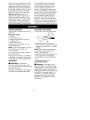 4
4
-
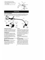 5
5
-
 6
6
-
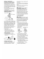 7
7
-
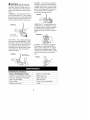 8
8
-
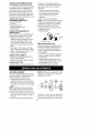 9
9
-
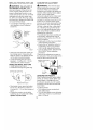 10
10
-
 11
11
-
 12
12
-
 13
13
-
 14
14
-
 15
15
-
 16
16
-
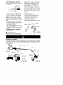 17
17
-
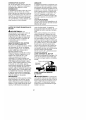 18
18
-
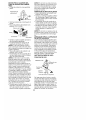 19
19
-
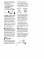 20
20
-
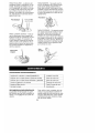 21
21
-
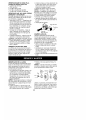 22
22
-
 23
23
-
 24
24
-
 25
25
-
 26
26
-
 27
27
-
 28
28


Craftsman 358.796270 El manual del propietario
- Categoría
- Podadoras de césped
- Tipo
- El manual del propietario
- Este manual también es adecuado para
en otros idiomas
- English: Craftsman 358.796270 Owner's manual
Artículos relacionados
-
Craftsman 358796270 El manual del propietario
-
-
-
-
-
-
-
-
-
Craftsman 358.795520 El manual del propietario