
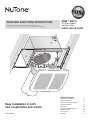
ZN80
n
ZN110
X2 | Multi-Speed
Ventilation Fan
INSTALLATION GUIDE
READ AND SAVE THESE INSTRUCTIONS
Installer: leave this guide with homeowner.
Register your product online at www.nutone.com/register.
Easy installation in both
new construction and retrofit
Table of Contents
Warnings and Cautions 2
Typical Installation 2
New Construction Installation 3
Retrofit Installation 7
Operation 12
Cleaning and Maintenance 12
Troubleshooting 12
Service Parts 13
Warranty 13
© 2017 Broan

ZN80
n
ZN110 Installation Guide
Page 2
WARNING
TO REDUCE THE RISK OF FIRE, ELECTRIC SHOCK, OR
INJURY TO PERSONS, OBSERVE THE FOLLOWING:
1. Use this unit only in the manner intended by the manufacturer.
If you have questions, contact the manufacturer at the address
or telephone number listed in the warranty.
2. Before servicing or cleaning unit, switch power off at service
panel and lock the service disconnecting means to prevent
power from being switched on accidentally. When the service
disconnecting means cannot be locked, securely fasten a
prominent warning device, such as a tag, to the service panel.
3. Installation work and electrical wiring must be done by a
qualified person(s) in accordance with all applicable codes
and standards, including fire-rated construction codes and
standards.
4. Sufficient air is needed for proper combustion and exhausting
of gases through the flue (chimney) of fuel burning equipment
to prevent backdrafting. Follow the heating equipment
manufacturer’s guideline and safety standards such as those
published by the National Fire Protection Association (NFPA),
and the American Society for Heating, Refrigeration and
Air Conditioning Engineers (ASHRAE), and the local code
authorities.
5. When cutting or drilling into wall or ceiling, do not damage
electrical wiring and other hidden utilities.
6. Ducted fans must always be vented to the outdoors.
7. Use only ON/OFF switch, mechanical timer or relay-switched
control.
8. Acceptable for use over a tub or shower when connected to
a GFCI (Ground Fault Circuit Interrupter) - protected branch
circuit.
9. This unit must be grounded.
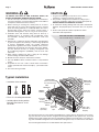
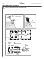
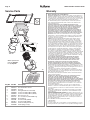
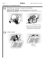
Typical Installation
CAUTION
1. For general ventilating use only. Do not use to exhaust
hazardous or explosive materials and vapors.
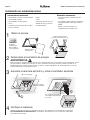
2. This product is designed for installation in ceilings up to a
12/12 pitch (45 degree angle). Duct connector must point up.
DO NOT MOUNT THIS PRODUCT IN A WALL.
3. To avoid motor bearing damage and noisy and/or unbalanced
impellers, keep drywall spray, construction dust, etc. off power
unit.
4. Please read specification label on product for further
information and requirements.
45° 45°
• Installation is the same for:
• Fits in 2" x 8" ceiling construction.
• Infinitely adjust the fan position
between joists from 14" to 24"
on center.
*Purchase
separately.
INSULATION*
(Place around and
over Fan Housing.)
ROOF CAP*
(with built-in
damper)
FAN
HOUSING
POWER
CABLE*
ROUND
DUCT*
ROUND
ELBOWS*
Seal gaps
around
Housing.
Seal duct
joints with
tape.
OR
Keep duct
runs short.
WALL CAP*
(with built-in
damper)
NOT FOR USE IN A COOKING AREA
Do not install above or inside this area
Floor
Cooking
Equipment
Joists I-Joists Trusses
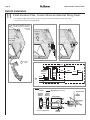
The ducting from this fan to the outside of the building has a strong effect on the air flow, noise and en-
ergy use of the fan. Use the shortest, straighest duct routing possible for best performance, and avoid
installing the fan with smaller ducts than recommended. Insulation around the ducts can reduce en-
ergy loss and inhibit mold growth. Fans installed with existing ducts may not achieve their rated airflow.
6-inch round rigid metal duct is recommended for best performance.

ZN80
n
ZN110 Installation Guide
Page 3
1
2
3
4
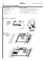
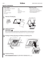
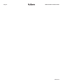
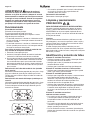
New Construction Installation
Tools needed
• Power screwdriver with a Phillips bit
• Phillips screwdriver
• Flathead screwdriver
• Pliers
• Wire insulation stripper
• Wire cutter
Materials needed
• 6" round metal ducting recommended for best performance.
Use of other ducting is acceptable but may impact performance.
• Roof cap or wall cap (built-in damper recommended)
• Tape to seal duct connections
• Electrical wiring and supplies per local code requirements
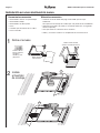
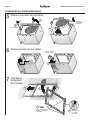
1
Remove Packaging
2
Install
Mounting
Frame
Parts Bag holds
Knockout Plate
and six (6)
screws
Remove
Instruction
Sheet
Punch out Mask from
packaging. See Step 6.

ZN80
n
ZN110 Installation Guide
Page 4
3
1
4
2
1
2
3
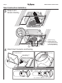
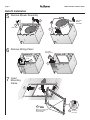
New Construction Installation
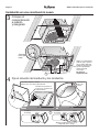
3
Snap-in and
Secure Housing
4
Attach Duct Connector and Ducting
Position Housing
between joists and
crimp channel on both
sides of Mounting Frame
to lock Housing in place.
Do not crimp Housing.
Screws from Parts Bag
Top and bottom flanges
go outside Housing
Insert tab into slot
inside Housing
Screw from
Parts Bag
6" to 4" Reducer provided in select models
Tape
Tape
Tape
6" Ducting
4" Ducting
snap!

ZN80
n
ZN110 Installation Guide
Page 5
3
4
1
2
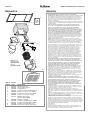
New Construction Installation
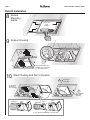
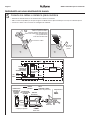
5
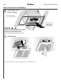
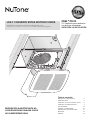
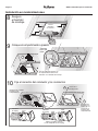
Connect Wires and Install Knockout Plate
• Run 120VAC electrical wiring to the installation location.
• Use proper UL-approved connectors to secure wiring to the Knockout Plate provided in Parts Bag.
• Connect wires as shown in wiring diagram.
Screw from
Parts Bag
Attach cable clamp to Knockout
Plate. Knockout Plate mounts to
outside of Housing and may be
oriented as desired.
Connect wires
LINE
IN
GRD GRD
WHT
BLK
BLK
BLK
RED
WHT
WHTRED
MASTER
ON/OFF
SWITCH
MASTER
ON/OFF
SWITCH*
MODE
SELECT
SWITCH
MODE
SELECT
SWITCH*
FAN
UNITSWITCH BOX
KNOCKOUT
PLATE
RECEPTACLE
120 VAC
LINE IN
SWITCH BOX
BLACK
WHITE
RED
GROUND (green or bare)
*
purchase separately
LINE
IN
GRD GRD
WHT
BLK
BLK
BLK
RED
WHT
WHTRED
MASTER
ON/OFF
SWITCH
MASTER
ON/OFF
SWITCH*
MODE
SELECT
SWITCH
MODE
SELECT
SWITCH*
FAN
UNITSWITCH BOX
KNOCKOUT
PLATE
RECEPTACLE
120 VAC
LINE IN
SWITCH BOX
BLACK
WHITE
RED
GROUND (green or bare)
*
purchase separately

ZN80
n
ZN110 Installation Guide
Page 6
1
2
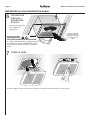
New Construction Installation
6
Insert Mask and
Finish Ceiling
7
Install Grille
See Page 12 for Operations, Cleaning and Maintenance, and Troubleshooting.
Mask protects unit
during construction.
Remove before
installing Grille.
• Install ceiling material.
• Cut out around Housing.
CAUTION
If the blower was unplugged, power must be
disconnected (see page 2, WARNING item 2)
before inserting motor plugs into control assembly.
IN ORDER TO PREVENT MOTOR/CONTROL DAMAGE:

ZN80
n
ZN110 Installation Guide
Page 7
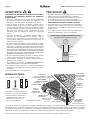
12" (30.5 cm)
1
2
Retrofit Installation
Parts Bag holds
Knockout Plate
and six (6)
screws
Existing ductwork and
wiring left in place
11" (27.9 cm)
parallel with joists
WARNING
Before removing existing fan, switch power off at service panel and lock the service disconnecting
means to prevent power from being switched on accidentally. When the service disconnecting means
cannot be locked, securely fasten a prominent warning device, such as a tag, to the service panel.
Examine the existing wiring to make sure it is not damaged. If any damage is found,
DO NOT CONTINUE INSTALLATION of this product. Contact a qualified person(s) for repair.
Remove
Instruction
Sheet
Punch out Mask from
packaging. See Step 12.
1
Remove Packaging
2
Switch Off Power
4
Examine Wiring
3
Enlarge Ceiling Opening and Remove Existing Fan
• Ruler
• Pencil
• Drywall saw
• Claw hammer or pry bar
• Utility knife
Materials needed
• Tape to seal duct connections
• Existing rigid duct will require the
addition of a short length of flexible duct
• Electrical wiring and supplies per
local code requirements
Tools needed
• Power screwdriver with a Phillips bit
• Phillips screwdriver
• Flathead screwdriver
• Pliers
• Wire insulation stripper
• Wire cutter

ZN80
n
ZN110 Installation Guide
Page 8
2
1
2
3
4
5
1
1
2
3
3
Retrofit Installation
5
Remove Blower Assembly
6
Remove Wiring Panel
7
Insert
Mounting
Frame
Both sides
Set aside
Blower
Assembly
Set aside
Wiring Panel
Set aside
screw
Bend up
four tabs
Remove screws from
Mounting Frame
and set aside

ZN80
n
ZN110 Installation Guide
Page 9
1
2
2
1
3
4
Retrofit Installation
Screw from
Parts Bag
Screws set
aside
in Step 7
Pull existing wiring into
Housing as it is inserted
into Mounting Frame
Pull existing
ductwork
into Housing
Insert tab into
slot inside
Housing
10
Attach Ducting and Duct Connector
8
Secure
Mounting
Frame
9
Snap-in Housing
snap!
6" to 4" Reducer provided in select models
Tape
Tape
Tape
6" Ducting
4" Ducting

ZN80
n
ZN110 Installation Guide
Page 10
2
1
4
5
6
3
LINE
IN
GRD GRD
WHT
BLK
BLK
BLK
RED
WHT
WHTRED
MASTER
ON/OFF
SWITCH
MASTER
ON/OFF
SWITCH*
MODE
SELECT
SWITCH
MODE
SELECT
SWITCH*
FAN
UNITSWITCH BOX
KNOCKOUT
PLATE
RECEPTACLE
120 VAC
LINE IN
SWITCH BOX
BLACK
WHITE
RED
GROUND (green or bare)
*
purchase separately
LINE
IN
GRD GRD
WHT
BLK
BLK
BLK
RED
WHT
WHTRED
MASTER
ON/OFF
SWITCH
MASTER
ON/OFF
SWITCH*
MODE
SELECT
SWITCH
MODE
SELECT
SWITCH*
FAN
UNITSWITCH BOX
KNOCKOUT
PLATE
RECEPTACLE
120 VAC
LINE IN
SWITCH BOX
BLACK
WHITE
RED
GROUND (green or bare)
*
purchase separately
Retrofit Installation
11
Install Knockout Plate, Connect Wires and Reinstall Wiring Panel
Screw from
Parts Bag
Attach cable clamp to Knockout
Plate. Knockout Plate mounts to
inside of Housing and may be
oriented as
desired.
Connect
wires
Screw set
aside in
Step 6
• Use proper UL-approved connectors to secure wiring to the Knockout Plate provided in Parts Bag.
• Connect wires as shown in wiring diagram.

ZN80
n
ZN110 Installation Guide
Page 11
1
2 3
1
2
1
2 3
1
2
Retrofit Installation
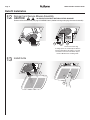
12
Reinsert and Secure Blower Assembly
13
Install Grille
If ceiling repairs are needed, place Mask in
Housing after Blower Assembly is secured.
See New Construction Installation Step 6.
Remove Mask before installing Grille.
Screws from Parts Bag
CAUTION
Power must be disconnected (see page 2, WARNING item 2) before inserting motor plugs into control assembly.
IN ORDER TO PREVENT MOTOR/CONTROL DAMAGE:

ZN80
n
ZN110 Installation Guide
Page 12
WARNING Before servicing or cleaning unit,
switch power off at service panel and lock the service
disconnecting means to prevent power from being
switched on accidentally. When the service disconnecting
means cannot be locked, securely fasten a prominent
warning device, such as a tag, to the service panel.
Operation
To Turn Fan ON
Turn the master switch ON.
It is normal for this ventilation fan to take approximately 5
seconds to start running after it is turned on.
• Fan will run at the certified airflow rate if the mode
select switch is ON.
• Fan will run at the user-adjustable airflow rate if the
mode select switch is OFF.
To Use Fan Time Delay Airflow Rate Change
1. Turn the master switch ON.
2. Turn the mode select switch ON - fan will run at the
certified airflow rate.
3. When the mode select switch is turned OFF, fan will
continue to run at the certified airflow rate until the
user-adjustable time delay has elapsed, and then will
automatically change to the user-adjustable airflow rate.
To Set the User-Adjustable Airflow Rate*
Using a small, flat-blade screwdriver, carefully rotate the
CFM adjustment until the arrow points to the desired
airflow rate.
To Set the User-Adjustable Time Delay*
Using a small, flat-blade screwdriver, carefully rotate the
TIME adjustment until the arrow points to the desired time
delay, shown in minutes.
* The user-adjustable controls are located in one corner
of the Fan Housing, behind the Grille.
To Turn Fan OFF
Turn the master switch OFF.
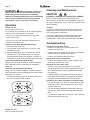
Cleaning and Maintenance
To Clean
For quiet and efficient operation, long life and attractive
appearance, remove Grille and vacuum interior of unit
with a dusting brush attachment.
The Motor is permanently lubricated and never needs
oiling. If the motor bearings are making excessive or
unusual noises, replace the Control Assembly and Motor.
Troubleshooting
Symptom: The fan does not run.
• Check for an open fuse or circuit breaker in the
building’s service panel.
• Check that the two (2) plug-in connections for the Motor
and the Control are seated firmly in place.
• Check that the Blower Wheel spins freely.
Symptom: The fan runs erratically.
• Check that the Blower Wheel is firmly attached to the
Motor shaft and both spin freely.
Symptom: The fan seems noisy.
• Check that the back draft damper in the fan’s Duct
Connector pivots freely. Screws used to attach the duct
to the Duct Connector may be preventing the damper
from opening.
• Check that the back draft damper in the wall or roof cap
pivots freely. These dampers are sometimes mistakenly
painted shut or obstructed by bird and insect debris.
Symptom: The fan does not properly ventilate the room.
• For spot ventilation, turn both the master switch and the
mode select switch ON to enable the fan to run at the
certified airflow rate.
• For spot ventilation followed by continuous ventilation,
increase the “TIME” setting of the user-adjustable time
delay.
• For continuous ventilation, increase the “CFM” setting of
the user-adjustable airflow rate.
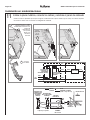
ZN80 User-adjustable controls
ZN110 User-adjustable controls
CAUTION
IN ORDER TO PREVENT MOTOR/CONTROL DAMAGE:
DO NOT remove motor plug to stop spinning motor.
Power must be disconnected (see WARNING at top left of
this page) before motor plug is removed or inserted into
control assembly.

ZN80
n
ZN110 Installation Guide
Page 13
5
10
1
3
6
7
4
8
9
11
2
Service Parts
Order replacement
parts by Part No.,
not by Key No.
Key No. Part No. Description
1 97018349 Mounting Frame
2 97018721 Knockout Plate & Screws
3 97018382 Housing
4 97018471 Wiring Panel/Harness Assembly
5 97020846 Control Assembly & Motor (ZN80)
97020845 Control Assembly & Motor (ZN110)
6 97018331 Duct Connector - 6"
7 99111513 6" to 4" Reducer (model ZN80 only)
8 99020301 Blower Wheel
9 97018768 Scroll Assembly (ZN110)
97019371 Scroll Assembly (ZN80)
10 97018532 Grille Assembly (includes 11)
11 99140208 Grille Spring (2 req’d)
Warranty
NuTone Ventilation Fans Limited Warranty
WARRANTY PERIOD: NuTone warrants to the original consumer purchaser of
its NuTone Ventilation Fans (the “Fan”) that your Fan will be materially free from
defects in materials or workmanship for a period of three (3) years from the date
of original purchase. This warranty does not cover accessories, such as speed
controls, that may be purchased separately and installed with the Fan.
The limited warranty period for replacement parts, and for Fans repaired or
replaced under this limited warranty, shall continue for the remainder of the
original warranty period.
NO OTHER WARRANTIES: THE FOREGOING WARRANTIES ARE
EXCLUSIVE AND IN LIEU OF ANY OTHER WARRANTIES, EXPRESS OR
IMPLIED. NUTONE DISCLAIMS AND EXCLUDES ALL OTHER EXPRESS
WARRANTIES, AND DISCLAIMS AND EXCLUDES ALL WARRANTIES
IMPLIED BY LAW, INCLUDING WITHOUT LIMITATION THOSE OF
MERCHANTABILITY AND FITNESS FOR A PARTICULAR PURPOSE. TO
THE EXTENT THAT APPLICABLE LAW PROHIBITS THE EXCLUSION OF
IMPLIED WARRANTIES, THE DURATION OF ANY APPLICABLE IMPLIED
WARRANTY IS LIMITED TO THE PERIOD SPECIFIED FOR THE EXPRESS
WARRANTY. Some states do not allow limitations on how long an implied
warranty lasts, so the above limitation may not apply to you. Any oral or written
description of the Fan is for the sole purpose of identifying it and shall not be
construed as an express warranty.
REMEDY: During the applicable limited warranty period, NuTone will, at its
option, provide replacement parts for, or repair or replace, without charge,
any Fan or part thereof, to the extent NuTone finds it to be covered by and in
breach of this limited warranty. NuTone will ship the repaired or replaced Fan
or replacement parts to you at no charge. You are responsible for all costs for
removal, reinstallation and shipping, insurance or other freight charges incurred
in the shipment of the Fan or part to NuTone. This warranty does not cover (a)
normal maintenance and service, (b) normal wear and tear, (c) any Fans or
parts which have been subject to misuse, abuse, abnormal usage, negligence,
accident, improper or insufficient maintenance, storage or repair (other than
repair by NuTone), (d) damage caused by faulty installation, or installation or
use contrary to recommendations or instructions, (e) any Fan that has been
moved from its original point of installation, (f) damage caused by environmental
or natural elements, (g) damage in transit, (h) natural wear of finish, (i) Fans in
commercial or nonresidential use, or (j) damage caused by fire, flood or other
act of God. This warranty covers only Fans sold in the United States or through
U.S. distributors authorized by NuTone.
EXCLUSION OF DAMAGES: NUTONE’S OBLIGATION TO PROVIDE
REPLACEMENT PARTS, OR REPAIR OR REPLACE, AT NUTONE’S
OPTION, SHALL BE YOUR SOLE AND EXCLUSIVE REMEDY UNDER
THIS LIMITED WARRANTY AND NUTONE’S SOLE AND EXCLUSIVE
OBLIGATION. NUTONE SHALL NOT BE LIABLE FOR INCIDENTAL,
INDIRECT, CONSEQUENTIAL OR SPECIAL DAMAGES ARISING OUT
OF OR IN CONNECTION WITH THE FAN, ITS USE OR PERFORMANCE.
Incidental damages include but are not limited to such damages as loss of time
and loss of use. Consequential damages include but are not limited to the cost
of repairing or replacing other property which was damaged if the Fan does not
work properly.
Some states do not allow the exclusion or limitation of incidental or
consequential damages, so the above limitation or exclusion may not apply to
you. This warranty gives you specific legal rights, and you may also have other
rights, which vary from state to state.
This warranty supersedes all prior warranties and is not transferable from the
original consumer purchaser.
NUTONE SHALL NOT BE LIABLE TO YOU, OR TO ANYONE CLAIMING
UNDER YOU, FOR ANY OTHER OBLIGATIONS OR LIABILITIES,
INCLUDING, BUT NOT LIMITED TO, OBLIGATIONS OR LIABILITIES
ARISING OUT OF BREACH OF CONTRACT OR WARRANTY, NEGLIGENCE
OR OTHER TORT OR ANY THEORY OF STRICT LIABILITY, WITH RESPECT
TO THE FAN OR NUTONE’S ACTS OR OMISSIONS OR OTHERWISE.
This warranty covers only replacement or repair of defective Fans or parts
thereof at NuTone’s main facility and does not include the cost of field service
travel and living expenses.
Any assistance NuTone provides to or procures for you outside the terms,
limitations or exclusions of this limited warranty will not constitute a waiver of
such terms, limitations or exclusions, nor will such assistance extend or revive
the warranty.
NuTone will not reimburse you for any expenses incurred by you in repairing
or replacing any defective Fan, except for those incurred with NuTone’s prior
written permission.
HOW TO OBTAIN WARRANTY SERVICE: To qualify for warranty service, you
must (a) notify NuTone at the address or telephone number stated below within
seven (7) days of discovering the covered defect, (b) give the model number
and part identification and (c) describe the nature of any defect in the Fan or
part. At the time of requesting warranty service, you must present evidence of
the original purchase date.
Broan, 926 West State Street, Hartford, WI 53027
(1-888-336-6151)
www.nutone.com
If you must send the Fan or part to NuTone, as instructed by NuTone, you must
properly pack the Fan or part—NuTone is not responsible for damage in transit.

ZN80
n
ZN110 Installation Guide
Page 14
99045849A

ZN80
n
ZN110
X2 | Ventilador para ventilación
con distintas velocidades
GUÍA PARA LA INSTALACIÓN
LEA Y CONSERVE ESTAS INSTRUCCIONES
Instalador: entregue esta guía al dueño de casa.
Registre su producto en línea en el sitio www.nutone.com/register.
Instalación sencilla tanto en
construcciones nuevas como
en modernizaciones
Tabla de contenido
Advertencias y precauciones 2
Instalación típica 2
Instalación en una construcción nueva 3
Instalación en modernizaciones 7
Funcionamiento 12
Limpieza y mantenimiento 12
Identificación y solución de fallas 12
Repuestos 13
Garantía 13

ZN80
n
ZN110 Guía para la instalación
Página 2
ADVERTENCIA
PARA REDUCIR EL RIESGO DE INCENDIO, SHOCK ELÉCTRICO
O DAÑOS A LAS PERSONAS, RESPETE LAS SIGUIENTES
INSTRUCCIONES:
1. Utilice esta unidad sólo para el uso que describe el fabricante.
Si tiene alguna pregunta, comuníquese con el fabricante a la
dirección o al número de teléfono que aparece en la garantía.
2. Antes de realizar el servicio o de limpiar la unidad, corte el
suministro eléctrico en el panel de servicio y bloquee el servicio
desconectando los medios que evitan que se conecte la energía
en forma accidental. Cuando no se puedan bloquear los medios
que desconectan el servicio, coloque un dispositivo de alarma
importante, como por ejemplo una etiqueta, en el panel de
servicio.
3. Las tareas de instalación y el cableado eléctrico deben ser
realizados por una persona/personas calificada/s según lo
establecen todos los códigos y las normas aplicables, entre los
que se incluyen códigos y normas para las construcciones con
calificación contra incendios.
4. Se requiere suficiente aire para una correcta combustión y escape
de gases a través del regulador de tiro (chimenea) del equipo
que funciona a combustible para evitar contracorrientes. Siga las
indicaciones del fabricante del equipo de calefacción y las normas
de seguridad como las publicadas por la Asociación Nacional de
Protección contra Incendios (NFPA) y la Sociedad Estadounidense
de Ingenieros en Calefacción, Refrigeración y Aire Acondicionado
(ASHRAE) y las autoridades locales regulatorias.
5. Al cortar o perforar las paredes o los techos, no dañe el cableado
eléctrico u otros servicios que no se encuentran a la vista.
6. Los ventiladores conectados a conductos siempre deben tener
ventilación hacia el exterior.
7. Use solamente un interruptor de ENCENDIDO/APAGADO, un
temporizador mecánico o un control de relé-interruptor.
8. La unidad sólo debe conectarse a un circuito de alimentación
protegido por un interruptor de circuito para fallas con conexión a
tierra (ICFT).
9. Esta unidad debe estar conectada a tierra.
Instalación típica
PRECAUCIÓN
1. Sólo debe utilizarse para ventilación general. No utilizar para
ventilar materiales y vapores peligrosos o explosivos.
2. Este producto está diseñado para instalarse en techos con
una pendiente de hasta 12/12 (ángulo de 45 grados).
El conector del conducto debe estar orientado hacia arriba.
NO MONTAR ESTE PRODUCTO SOBRE LA PARED.
3. Para evitar daños en los cojinetes del motor y/o impulsores
desbalanceados y ruidosos, mantenga el rociado para los
paneles de yeso, el polvo de la construcción, etc., lejos de la
unidad eléctrica.
4. Lea la etiqueta con las especificaciones del producto para
obtener más información y conocer los requisitos.
45° 45°
• La instalación es similar para:
• Se adapta a la construcción de un
techo de 5 cm x 20 cm (2 x 8 pulg.)
• Ajustar sin límite la posición del
ventilador entre las vigas a una
distancia de 35,5 cm a 61 cm
(14 a 24 pulg.) del centro.
NO UTILIZAR EN UN ÁREA DONDE SE COCINA
No instalar sobre o dentro de esta área
Piso
Artefacto para
cocinar
Vigas Vigas en Cerchas
forma de I
*Comprar por separado.
AISLACIÓN*
(Colocar alrededor y sobre
el compartimiento para el ventilador).
CAPUCHÓN
PARA TEJADO*
(con regulador
de tiro
incorporado)
VENTILADOR
COMPARTIMIENTO
CABLE DE
ALIMENTACIÓN*
CONDUCTO
CIRCULAR*
CODOS
CIRCULARES*
Sellar las
cavidades
alrededor del
compartimiento.
Sellar las uniones
del conducto
con cinta.
O
Asegurarse
de que los
conductos
sean cortos.
CAPUCHÓN
DE PARED*
(con regulador
de tiro incorporado)
Los conductos desde este ventilador hacia el exterior del edificio tienen un gran efecto sobre el flujo de aire, el ruido y el uso de energía
del ventilador. Utilice el tramo de conductos más corto y recto posible para obtener un desempeño óptimo y evite instalar el ventilador
con conductos menores que los recomendados. El aislamiento alrededor de los conductos puede reducir la pérdida de energía e inhibir
el desarrollo de moho. Los ventiladores instalados en conductos existentes podrían no obtener el flujo de aire nominal.
Para un mejor desempeño, se recomienda utilizar conductos metálicos redondos y rígidos de 6 pulg. (15,2 cm).

ZN80
n
ZN110 Guía para la instalación
Página 3
1
2
3
4
La bolsa de las
piezas contiene
una placa
metálica y seis
(6) pernos
Retire la hoja de
instrucciones
Retire la máscara del
envase. Consulte el Paso 6.
Instalación en una construcción nueva
Herramientas necesarias
• Destornillador eléctrico con punta Phillips
• Destornillador Phillips
• Destornillador de cabeza plana
• Pinza
• Pelacable para la aislación de los cables
• Pinza cortacable
Materiales necesarios
• Conducto circular de metal de 6 pulg. recomendado para un mejor
rendimiento.
Se acepta el uso de otro tipo de conducto pero esto puede afectar el rendimiento.
• Capuchón para tejado o de pared (se recomienda utilizar uno con regulador
de tiro incorporado)
• Cinta para sellar las conexiones de los conductos
• Cables y accesorios eléctricos en cumplimiento de la normativa local
1
Retire el envase
2
Instale
el bastidor
de montaje

ZN80
n
ZN110 Guía para la instalación
Página 4
3
1
4
2
1
2
3
Instalación en una construcción nueva
3
Coloque el
compartimiento
a presión
y asegúrelo
4
Fije el conector del conducto y los conductos
Ubique el compartimiento
entre las vigas y ajuste el
canal a ambos lados del
bastidor de montaje para
que el compartimiento
quede asegurado
en su lugar.
No ajuste el
compartimiento.
Pernos de la bolsa de piezas
Las bridas superior e inferior
deben ir por fuera del compartimiento
Introduzca la pestaña en
la ranura en el interior del
compartimiento
Perno de la
bolsa de
piezas
Algunos modelos cuentan con un
adaptador de 6 a 4 pulg.
Cinta
CintaCinta
Conducto
de 6 pulg.
Conducto
de 4 pulg.
¡Presione
hasta que
trabe!

ZN80
n
ZN110 Guía para la instalación
Página 5
3
4
1
2
EN
LÍNEA
TIERRA TIERRA
BLAN
NEG
NEG
NEG
ROJO
BLAN
BLANROJO
INTERRUPTOR
PRINCIPAL DE
ENCENDIDO/
APAGADO (ON/OFF)
INTERRUPTOR
PRINCIPAL DE
ENCENDIDO/
APAGADO
(ON/OFF)*
INTERRUPTOR
DE LA SELECCIÓN
DE MODO
INTERRUPTOR
DE LA SELECCIÓN
DE MODO*
VENTILADOR
UNIDADTABLERO ELÉCTRICO
PLACA
METÁLICA
RECEPTÁCULO
EN LÍNEA
DE 120 VCA
TABLERO
ELÉCTRICO
*
comprar por separado
NEGRO
BLANCO
ROJO
CONEXIÓN A TIERRA
(verde o sin protección)
Instalación en una construcción nueva
5
Conecte los cables e instale la placa metálica
• Extienda un cableado eléctrico de 120 VCA hasta el sitio de la instalación.
• Utilice conectores aprobados por UL para asegurar el cableado hasta la placa metálica que se incluye en la bolsa de piezas.
• Conecte los cables como se muestra en el diagrama de cableado.
Perno de la
bolsa de
piezas
Fije las abrazaderas de los
cables a la placa metálica.
La placa metálica debe montarse
en el exterior del compartimiento
y se la puede ubicar
en la dirección deseada.
Conecte los cables

ZN80
n
ZN110 Guía para la instalación
Página 6
1
2
Instalación en una construcción nueva
6
Introduzca la
máscara y
acondicione
el techo
7
Instale la rejilla
Consulte la página 12 sobre Funcionamiento, Limpieza y mantenimiento e Identificación y solución de fallas.
La máscara protege
la unidad durante la
construcción. Retírela
antes de instalar la
rejilla.
• Instale el material del techo.
• Corte alrededor del
compartimiento.
PRECAUCIÓN
Si el motor estaba desconectado, se debe desconectar
la electricidad (vea la página 2, ADVERTENCIA, punto 2)
antes de insertar los enchufes del motor en el conjunto de
control.
PARA PREVENIR DAÑOS EN EL MOTOR/CONTROL:

ZN80
n
ZN110 Guía para la instalación
Página 7
30,5 cm (12 pulg.)
1
2
Instalación en modernizaciones
La bolsa de
las piezas
contiene una
placa metálica
y seis (6) pernos
Los conductos existentes
y los cables permanecerán
en su sitio
ADVERTENCIA
Antes de retirar el ventilador existente, desconecte el suministro eléctrico en el panel de servicio y bloquee el servicio
desconectando los medios para evitar que se active el suministro de energía en forma accidental. Cuando no se
puedan bloquear los medios que desconectan el servicio, coloque un dispositivo de alarma importante, como por
ejemplo una etiqueta, en el panel de servicio.
Verifique el cableado existente para asegurarse de que no esté dañado. En caso de determinar algún daño,
NO CONTINÚE CON LA INSTALACIÓN de este producto. Comuníquese con la(s) persona(s) calificada(s)
para realizar la reparación.
Retire la hoja de
instrucciones
Retire la máscara del
envase. Consulte el Paso 12.
1
Retire el envase
2
Desconecte el suministro de energía
4
Verifique el cableado
3
Aumente la abertura del techo y retire el ventilador existente
• Regla
• Lápiz
• Sierra para paneles de yeso
• Martillo de orejas o palanca
• Cuchillo multiuso
Herramientas necesarias
• Destornillador eléctrico con punta Phillips
• Destornillador Phillips
• Destornillador de cabeza plana
• Pinza
• Pelacable para la aislación de los cables
• Pinza cortacable
27,9 cm (11 pulg.)
paralelo a las vigas
Materiales necesarios
• Cinta para sellar las conexiones de los
conductos
•
Los conductos rígidos existentes requerirán el
agregado de tramos cortos de un conducto
flexible
• Cables y accesorios eléctricos en
cumplimiento de la normativa local

ZN80
n
ZN110 Guía para la instalación
Página 8
2
1
2
3
4
5
1
1
2
3
3
Instalación en modernizaciones
5
Retire el conjunto del ventilador
6
Retire el panel con los cables
7
Introduzca
el bastidor
de montaje
Ambos lados
Aparte el
conjunto del
ventilador
Aparte el panel
con los cables
Aparte el
perno
Despliegue
las cuatro
pestañas
Retire los pernos del
bastidor de montaje
y apártelos

ZN80
n
ZN110 Guía para la instalación
Página 9
1
2
2
1
3
4
Instalación en modernizaciones
Perno de la
bolsa de piezas
Pernos
apartados
en el Paso 7
Tire del cableado existente en
el compartimiento mientras lo
introduce en el bastidor de montaje
Introduzca el conducto
existente en el
compartimiento
Introduzca la
pestaña en la
ranura que se
encuentra en
el interior del
compartimiento
10
Fije el conector del conducto y los conductos
8
Asegure
el bastidor
de montaje
9
Coloque el compartimiento a presión
Cinta
Cinta
Cinta
¡Presione
hasta que
trabe!
Algunos modelos cuentan
con un adaptador de 6 a 4 pulg.
Conducto
de 6 pulg.
Conducto
de 4 pulg.

ZN80
n
ZN110 Guía para la instalación
Página 10
2
1
4
5
6
3
EN
LÍNEA
TIERRA TIERRA
BLAN
NEG
NEG
NEG
ROJO
BLAN
BLANROJO
INTERRUPTOR
PRINCIPAL DE
ENCENDIDO/
APAGADO (ON/OFF)
INTERRUPTOR
PRINCIPAL DE
ENCENDIDO/
APAGADO
(ON/OFF)*
INTERRUPTOR
DE LA SELECCIÓN
DE MODO
INTERRUPTOR
DE LA SELECCIÓN
DE MODO*
VENTILADOR
UNIDADTABLERO ELÉCTRICO
PLACA
METÁLICA
RECEPTÁCULO
EN LÍNEA
DE 120 VCA
TABLERO
ELÉCTRICO
*
comprar por separado
NEGRO
BLANCO
ROJO
CONEXIÓN A TIERRA
(verde o sin protección)
Instalación en modernizaciones
11
I
nstale la placa metálica, conecte los cables y reinstale el panel de cableado
Perno
de la bolsa
de piezas
Fije las abrazaderas de los cables
a la placa metálica. La placa
metálica debe montarse en el
interior del
compartimiento
y se la puede
ubicar en la
orientación
deseada.
Conecte
los cables
Perno
apartado
en el
Paso 6
• Utilice conectores aprobados por UL para asegurar el cableado hasta la placa metálica que se incluye en la bolsa de piezas.
• Conecte los cables como se muestra en el diagrama de cableado.
EN
LÍNEA
TIERRA TIERRA
BLAN
NEG
NEG
NEG
ROJO
BLAN
BLANROJO
INTERRUPTOR
PRINCIPAL DE
ENCENDIDO/
APAGADO (ON/OFF)
INTERRUPTOR
PRINCIPAL DE
ENCENDIDO/
APAGADO
(ON/OFF)*
INTERRUPTOR
DE LA SELECCIÓN
DE MODO
INTERRUPTOR
DE LA SELECCIÓN
DE MODO*
VENTILADOR
UNIDADTABLERO ELÉCTRICO
PLACA
METÁLICA
RECEPTÁCULO
EN LÍNEA
DE 120 VCA
TABLERO
ELÉCTRICO
*
comprar por separado
NEGRO
BLANCO
ROJO
CONEXIÓN A TIERRA
(verde o sin protección)

ZN80
n
ZN110 Guía para la instalación
Página 11
1
2 3
1
2
Instalación en modernizaciones
12
Reintroduzca y asegure el conjunto del ventilador
13
Instale la rejilla
Si fuera necesario efectuar reparaciones en el techo,
coloque la máscara en el compartimiento después
de asegurar el conjunto del ventilador. Consulte el
Paso 6 de Instalación en una construcción nueva.
Retire la máscara antes de instalar la rejilla.
Pernos de la bolsa de piezas
PRECAUCIÓN
Debe desconectar la electricidad (vea la página 2, ADVERTENCIA, punto 2) antes de insertar los enchufes
del motor en el conjunto de control.
PARA PREVENIR DAÑOS EN EL MOTOR/CONTROL:
1
2 3
1
2

ZN80
n
ZN110 Guía para la instalación
Página 12
ADVERTENCIA Antes de realizar el
servicio o de limpiar la unidad, corte el suministro
eléctrico en el panel de servicio y bloquee el servicio
desconectando los medios que evitan que se conecte
la energía en forma accidental. Cuando no se puedan
bloquear los medios que desconectan el servicio,
coloque un dispositivo de alarma importante, como
por ejemplo una etiqueta, en el panel de servicio.
Funcionamiento
Encendido del ventilador
Encienda el interruptor principal.
Es normal que este ventilador para tomar
aproximadamente 5 segundos para empezar a correr
después de que se encienda.
• El ventilador comenzará a funcionar al índice de caudal
de aire certificado, si el interruptor selector de modo se
encuentra activado.
• El ventilador comenzará a funcionar al índice de caudal
de aire ajustable por el usuario, si el interruptor selector
de modo se encuentra desactivado.
Para utilizar el cambio en el índice de caudal de aire
en el retardo del tiempo del ventilador
1. Encienda el interruptor principal.
2. Accione el interruptor selector de modo: el ventilador
funcionará al índice de caudal de aire certificado.
3. Una vez desactivado el interruptor selector de modo, el
ventilador seguirá funcionando al índice de caudal de
aire certificado hasta que haya transcurrido el retardo
del tiempo ajustable por el usuario y luego cambiará en
forma automática al índice del caudal de aire ajustable
por el usuario.
Determinación del índice del caudal de aire ajustable
por el usuario*
Utilizando un destornillador pequeño de punta plana, haga
girar con cuidado el ajuste de pies cúbicos por minuto
(CFM) hasta que la flecha indique el índice del caudal de
aire deseado.
Determinación del retardo del tiempo ajustable por el
usuario*
Utilizando un destornillador pequeño de punta plana, haga
girar con cuidado el ajuste del tiempo (TIME) hasta que
la flecha indique el retardo de tiempo deseado, que se
mostrará en minutos.
* Los controles ajustables por el usuario están ubicados
en una de las esquinas del compartimiento del
ventilador, detrás de la rejilla.
Desconexión del ventilador
Desconecte el interruptor principal.
Limpieza y mantenimiento
Limpieza
Para un funcionamiento silencioso y eficiente, una vida
útil prolongada y una atractiva apariencia, retire la rejilla y
aspire el interior de la unidad con un accesorio en forma
de cepillo para eliminar el polvo.
El motor siempre permanecerá lubricado y no será
necesario lubricarlo. Si los cojinetes del motor produjeran
demasiado ruido o ruidos inusuales, reemplace el conjunto
del control y el motor.
Identificación y solución de fallas
Síntoma: El ventilador no funciona.
• Verifique la presencia de un fusible o interruptor abierto
en el panel de servicios del edificio.
• Verifique que las dos (2) conexiones del motor y del
control estén bien unidas.
• Verifique que el ventilador centrífugo gire libremente.
Síntoma: El ventilador funciona en forma errática.
• Verifique que el ventilador centrífugo esté fijo al eje del
motor y que ambos giren libremente.
Síntoma: El ventilador genera ruidos.
• Verifique que el regulador de tiro para la contracorriente
en el conector del conducto del ventilador gire
libremente. Los pernos que se utilizan para fijar el
conducto al conector del conducto pueden estar
evitando que se abra el regulador de tiro.
• Verifique que el regulador de tiro para la contracorriente
en el capuchón de la pared o del tejado gire libremente.
A menudo, estos reguladores se pintan por error y
se cierran o se obstruyen por los residuos de aves e
insectos.
Síntoma: El ventilador no ventila el
ambiente en forma correcta.
• Para ventilar el sitio, encienda el interruptor principal
y el interruptor selector de modo para permitir que
el ventilador funcione al índice de caudal de aire
certificado.
• Para ventilar el sitio después de la ventilación continua,
aumente la configuración del tiempo del retardo del
tiempo ajustable por el usuario.
• Para la ventilación continua, aumente el ajuste de pies
cúbicos por minuto del índice de caudal de aire ajustable
por el usuario.
Controles ZN80 ajustables por el usuario
Controles ZN110 ajustables por el usuario
PRECAUCIÓN
PARA PREVENIR DAÑOS EN EL MOTOR/CONTROL:
NO retire el enchufe del motor para detener el giro del
motor. La electricidad debe estar desconectada (vea la
ADVERTENCIA en la parte superior izquierda de esta
página) antes de retirar o insertar el enchufe del motor en
el conjunto de control.

ZN80
n
ZN110 Guía para la instalación
Página 13
5
10
1
3
6
7
4
8
9
11
2
Repuestos Garantía
Nro de Nro de
artículo pieza Descripción
1 97018349 Bastidor de montaje
2 97018721 Placa metálica y pernos
3 97018382 Compartimiento
4 97018471 Conjunto de panel de cableado/arnés
5 97020846 Montaje de control y motor (ZN80)
97020845 Conjunto de control y motor (ZN110)
6 97018331 Conector del conducto - 6 pulg.
7 99111513
Adaptador de 6 a 4 pulg.
(só l o en la modelo ZN80)
8 99020301 Ventilador centrífugo
9 97018768 Conjunto de desplazamiento (ZN110)
97019371 Conjunto de desplazamiento (ZN80)
10 97018532 Conjunto de la rejilla (incluye 11)
11 99140208 Resorte de la rejilla (se requieren 2)
Ordenar los
repuestos por
Nro de pieza,
no por
Nro de artículo
Garantía limitada para los ventiladores para ventilación NuTone
PERÍODO DE LA GARANTÍA: NuTone le garantiza al comprador consumidor original
de los Ventiladores para ventilación NuTone (el “Ventilador”) que su ventilador no
presentará defectos de material o de mano de obra durante un período de tres (3)
años a partir de la fecha de la compra original. Esta garantía no cubre accesorios
tales como controles de velocidad que pueden adquirirse por separado y que se
instalan con el Ventilador.
El período de garantía limitada para los repuestos y para los Ventiladores reparados
o reemplazados bajo esta garantía limitada continuará durante el período restante de
la garantía original.
AUSENCIA DE OTRAS GARANTÍAS: LAS SIGUIENTES GARANTÍAS SON
EXCLUSIVAS Y SE RELACIONAN CON TODA OTRA GARANTÍA EXPRESA
O IMPLÍCITA. NUTONE RENUNCIA Y EXCLUYE TODA OTRA GARANTÍA
EXPRESA Y RENUNCIA Y EXCLUYE TODA GARANTÍA QUE EXIJA LA LEY,
INCLUYENDO PERO NO LIMITÁNDOSE A AQUELLAS RELACIONADAS CON LA
COMERCIABILIDAD Y LA APTITUD PARA UN FIN EN PARTICULAR. EN TANTO
LA LEY CORRESPONDIENTE PROHÍBA LA EXCLUSIÓN DE LAS GARANTÍAS
IMPLÍCITAS, LA DURACIÓN DE TODA GARANTÍA IMPLÍCITA APLICABLE SE
LIMITA AL PERÍODO ESPECIFICADO PARA LA GARANTÍA EXPRESA. Algunos
estados no permiten limitaciones sobre cuál es la duración de una garantía implícita,
de modo que la limitación antes mencionada puede no aplicarse a su caso. Toda
descripción escrita u oral del Ventilador es al sólo fin de identificarlo y no deberá
tomarse como una garantía expresa.
COMPENSACIÓN: Durante el transcurso del período aplicable de la garantía
limitada, NuTone, a su discreción, proporcionará repuestos, reparación o reemplazo,
en forma gratuita, para cualquier Ventilador o alguna de sus piezas, en tanto NuTone
considere que está cubierto por y en violación de esta garantía limitada. NuTone
le enviará el Ventilador reparado o su reemplazo o los repuestos en forma gratuita.
Usted es responsable de los costos de retiro, reinstalación y envío, seguros y otros
cargos por flete que se generen durante el transporte del Ventilador o del repuesto a
NuTone. Esta garantía no cubre (a) el mantenimiento y el servicio normales,
(b) el desgaste normal, (c) todo Ventilador o repuesto sometido a mal uso, abuso,
uso anormal, negligencia, accidente, mantenimiento inadecuado o insuficiente,
conservación o reparación (que no sea la reparación realizada por NuTone),
(d) daños provocados por instalación defectuosa o instalación o uso contrario a
las recomendaciones o instrucciones, (e) todo Ventilador que se haya trasladado
del punto original de instalación, (f) daño provocado por elementos naturales o
ambientales, (g) daño durante el transporte, (h) desgaste natural del acabado,
(i) Ventiladores en uso comercial o no residencial o (j) daño provocado por incendio,
inundación u otro caso fortuito. Esta garantía cubre sólo a los Ventiladores que se
venden en los Estados Unidos o a través de representantes de los Estados Unidos
autorizados por NuTone.
EXCLUSIÓN DE DAÑOS: LA OBLIGACIÓN DE NUTONE DE PROPORCIONAR
REPUESTOS O LA REPARACIÓN O EL REEMPLAZO, A DISCRECIÓN DE
NUTONE, SERÁ LA ÚNICA Y EXCLUSIVA COMPENSACIÓN BAJO EL AMPARO
DE ESTA GARANTÍA LIMITADA Y LA ÚNICA Y EXCLUSIVA OBLIGACIÓN DE
NUTONE. NUTONE NO SERÁ RESPONSABLE DE DAÑOS INCIDENTALES,
INDIRECTOS, EMERGENTES O ESPECIALES QUE SURJAN DE O EN
CONEXIÓN CON EL VENTILADOR, SU USO O FUNCIONAMIENTO. Los daños
incidentales incluyen, pero no se limitan a, daños tales como pérdida de tiempo
o pérdida del uso. Los daños emergentes incluyen pero no se limitan al costo de
la reparación o reemplazo de otra propiedad que haya sufrido daños en caso del
malfuncionamiento del Ventilador.
Algunos estados no permiten la exclusión o la limitación de los daños incidentales
o emergentes, de modo que la limitación o la inclusión antes mencionada puede no
aplicarse a su caso. Esta garantía le otorga derechos legales específicos y usted
también podrá gozar de otros derechos que varían según el estado.
Esta garantía reemplaza a todas las garantías anteriores y no es transferible por el
comprador consumidor original.
NUTONE NO SERÁ RESPONSABLE ANTE USTED, O ANTE CUALQUIER
PERSONA QUE RECLAME EN SU NOMBRE, DE NINGUNA OTRA OBLIGACIÓN
O RESPONSABILIDAD, QUE INCLUYE, PERO NO SE LIMITA A, LAS
OBLIGACIONES O RESPONSABILIDADES QUE SURJAN DE LA VIOLACIÓN
DEL CONTRATO O DE LA GARANTÍA, NEGLIGENCIA U OTRO AGRAVIO
O CUALQUIER TEORÍA SOBRE LA RESPONSABILIDAD ESTRICTA, CON
RESPECTO AL VENTILADOR O A LOS ACTOS U OMISIONES U OTROS POR
PARTE DE NUTONE.
Esta garantía cubre sólo el reemplazo o la reparación de los Ventiladores o piezas
con defectos del mismo en la plana principal de NuTone y no incluye los costos del
transporte del servicio en campo ni los gastos de estadía.
Toda asistencia que NuTone le brinde o procure fuera de los términos, las
limitaciones o las exclusiones de esta garantía limitada no constituirá una renuncia a
dichos términos, limitaciones o exclusiones ni dicha asistencia extenderá o revivirá la
garantía.
NuTone no le reembolsará ningún gasto en el que usted incurra en la reparación o
reemplazo de cualquier Ventilador defectuoso excepto por aquellos en los que incurra
previo a la obtención del permiso por escrito de NuTone.
CÓMO OBTENER EL SERVICIO DE LA GARANTÍA: Para calificar para el servicio
de garantía, usted debe (a) notificar a NuTone el domicilio o el número de teléfono
que figura a continuación dentro de los siete (7) días de haber descubierto el defecto
cubierto, (b) brindar el número de modelo y la identificación de la pieza y (c) describir
la naturaleza de cualquier defecto del Ventilador o de la pieza. A la hora de solicitar el
servicio de garantía, usted debe presentar prueba de la fecha original de la compra.
Broan, 926 West State Street, Hartford, WI 53027
(1-888-336-6151)
www.nutone.com
Si usted debe enviar el Ventilador o la pieza a NuTone, según las indicaciones de
NuTone, debe embalar el Ventilador o la pieza en forma adecuada. NuTone no es
responsable de los daños ocasionados durante el transporte.

ZN80
n
ZN110 Guía para la instalación
Página 14
99045849A
-
 1
1
-
 2
2
-
 3
3
-
 4
4
-
 5
5
-
 6
6
-
 7
7
-
 8
8
-
 9
9
-
 10
10
-
 11
11
-
 12
12
-
 13
13
-
 14
14
-
 15
15
-
 16
16
-
 17
17
-
 18
18
-
 19
19
-
 20
20
-
 21
21
-
 22
22
-
 23
23
-
 24
24
-
 25
25
-
 26
26
-
 27
27
-
 28
28


NuTone ZN110 Guía de instalación
- Tipo
- Guía de instalación
- Este manual también es adecuado para
En otros idiomas
- English: NuTone ZN110 Installation guide
Documentos relacionados
-
NuTone ZN80M Guía de instalación
-
-
-
-
-
-
-
-
-