koban KIT AUDITOR El manual del propietario
- Categoría
- Medir, probar
- Tipo
- El manual del propietario
Este manual también es adecuado para

KCER-01MF
TEST MULTIFUNCIÓN

2 www.grupotemper.com
KCER-01MF
Comprobador de seguridad multifunción
Índice
1 Consideraciones de seguridad - (Página 4)
1.1 Símbolos Internacionales – (Página 4)
1.2- Terminología – (Página 4)
1.3- Advertencias – (Página 4)
1.4- Precaución – (Página 4)
1.5- Declaración de conformidad – (Página 5)
1.6- Códigos de error – (Página 6)
2- Especificaciones – (Página 7)
3- Especificaciones generales – (Página 11)
4- Instrumento - (Página 16)
4.1- Vista frontal – (Página 16)
4.2- Panel de conectores – (Página 18)
4.3- Batería y fusible – (Página 19)
4.4- Accesorios – (Página 19)
4.5- Descripción de la pantalla – (Página 20)
5- Cómo utilizar el Multifunción – (Página 24)
5.1- Símbolos y mensajes importantes durante la medición – (Página 24)
5.2- Uso del LOOP / PFC, el voltaje, secuencia de fase y la función RCD –
(Página 29)
6- Uso de las diferentes funciones: Insulation (Aislamiento), RE
(Resistencia a tierra) y LOW OHM - (Página 47)
6.1 Aislamiento Función / Menú – (Página 48)
6.2- Resistencia de aislamiento: Pantalla / Configuración de interruptor y
terminal – (Página 50)
6.3- Uso de la función RE – (Página 51)
6.4- Resistencia Tierra: Pantalla / Configuración de interruptor y terminal –
(Página 51)
6.5- Para medir la resistencia de Tierra – (Página 52)
6.6- RE Funcionamiento del menú – (Página 52)
6.7- Uso de la función LOW OHM – (Página 53)
7- Menú - (Página 55)
8- Configuración del sistema – (Página 56)
8.1- Idiomas – (Página 57)
8.2- Fecha / Hora – (Página 57)
8.3- TV – (Página 58)
8.4- Memoria – (Página 58)
8.5- Apagado automático de la pantalla – (Página 59)
8.6- Función de apagado automático del multifunción – (Página 59)
8.7- Ajustes predeterminados del sistema – (Página 60)

www.grupotemper.com 3
KCER-01MF
Comprobador de seguridad multifunción
8.8- Actualización del sistema – (Página 60)
9- Configuraciones Data Record, Datalog, Bluetooth - (Página 61)
9.1- Bluetooth - (Página 61)
9.2- Data Record – (Página 62)
9.3- Datalog – (Página 62)
10- Data Record – (Página 63)
10.1- Borrar archivos – (Página 64)
10.2- Data record Menú – (Página 65)
10.3- Gráficas – (Página 66)
10.4- Datalog Color – (Página 68)
11- Software – (Página 68)
12- Dispositivo USB – (Página 69)

4 www.grupotemper.com
KCER-01MF
Comprobador de seguridad multifunción
ADVERTENCIA!
Usted debe leer y entender completamente las Consideraciones de
Seguridad de este manual antes de utilizer el instrumento
1. CONSIDERACIONES DE SEGURIDAD
Este manual contiene instrucciones relacionadas con el uso seguro y
funcionamiento apropiado del instrumento. Si no se cumplen, el usuario
podría estar expuesto a peligro y el instrumento a posibles daños.
1.1. Símbolos internacionales
: ADVERTENCIA!
: ¡PRECAUCIÓN! Presencia de tensión
: Tierra
: Doble aislamiento (Aislamiento clase II)
: Fusible
: Prohibido el uso para el Sistema Eléctrico que utiliza una tensión
por encima de 550V
: Conformidad con las Normativas Europeas
1.2. Terminología
El término ADVERTENCIA, tal y como se utiliza en este manual, define
una condición o un procedimiento que podría conducir a una lesión o
accidente grave. El término PRECAUCIÓN define una condición o acción
que podría conducir a que el instrumento quede defectuoso durante el
proceso de prueba.
.
1.3 Advertencias
_ Asegúrese de leer y entender completamente las instrucciones
contenidas en este manual antes de su uso.
_ Este instrumento no es intrínsecamente seguro; por lo tanto, no utilice el
instrumento en entornos peligrosos.
_ Para evitar incendio y/o impacto eléctrico, no utilice el instrumento en
entornos mojados, anegados o ligeramente húmedos.
_ Antes de su uso, compruebe si el instrumento funciona correctamente. Si
hay indicación de algún síntoma/símbolos de funcionamiento incorrecto o
anormalidades, no lo utilice ni informe aMTi Instruments.
_ Los usuarios que pudieran estar expuestos a tensiones por encima de la
banda baja extra (50V ac o 120V dc) deberían ser competentes y estar

www.grupotemper.com 5
KCER-01MF
Comprobador de seguridad multifunción
conscientes de los requisitos de GS 38 relacionados con el uso del
instrumento y las sondas y cables asociados, etc.
_ Asegúrese de que sus dedos que sostienen las sondas de prueba estén
colocados detrás de las líneas de seguridad de las sondas de prueba.
_ NO ABRA EL INSTRUMENTO.
_ Si el fusible interno (dispositivo protector) funciona, reemplace con un
dispositivo del mismo tipo y capacidad. Si funciona de nuevo, busque
consejo profesional. NO REEMPLACE EL FUSIBLE E INTENTE DE
NUEVO.
_ Al llevar a cabo “pruebas muertas”, asegúrese de que se ha confirmado,
antes de la conexión de los cables del instrumento, que el circuito bajo
prueba está “muerto” y asegurado en la posición APAGADO utilizando
métodos apropiados.
_ La condición de la batería está indicada por un sonido. Compruebe y
reemplace si hace falta.
_ No pruebe un circuito o sistemas eléctricos donde la tensión sea superior
a 550V.
_ Asegure en todo momento que los cables cumplan con GS (según se
suministran) y que no estén dañados.
1.4. Precaución
No cambie las funciones en el instrumento de prueba con los cables de
prueba en su lugar, es decir, cambiando de una “prueba muerta” a una
prueba donde el suministro que se requiere podría dañar el instrumento.
1.5. Declaración de Conformidad
Este instrumento ha sido probado de acuerdo con las siguientes
regulaciones:
_ EN 61326: Equipos eléctricos para medición, control y uso de
laboratorio.
_ EN 61010-1: Requisitos de seguridad para equipos eléctricos para
medición, control y uso de laboratorio – Parte 1: Requisitos generales.
_ BS EN61557: Seguridad eléctrica en sistemas de distribución de tensión
baja hasta 1000V a.c. y 1500V d.c.
Equipos para prueba, medición o supervisión de medidas protectoras.
Parte 1 Requisitos generales
Parte 2 Resistencia al aislamiento
Parte 3 Resistencia de bucle
Parte 4 Resistencia de conexión de tierra y enlace equipotencial
Parte 6 Dispositivos de corriente residual (RCDs) en sistemas TT y TN
Parte 7 Secuencia de fase
Parte 10 Equipo de medición combinada

6 www.grupotemper.com
KCER-01MF
Comprobador de seguridad multifunción
1.6. Códigos de error
Diversas condiciones de error son detectados por el multifunción y se
indican con el icono "Err", y un número de error en la pantalla principal.
Véase la Tabla 1. Estas condiciones de error desactivan la prueba y, si es
necesario, detienen una prueba en funcionamiento.
Tabla 1. Códigos de error
Tipo de error
Código
Solución
Fallo de tensión
1
Comprueba la instalación, en particular,
la tensión entre Neutro y PE.
Sobrecalentamiento
2
Espere hasta que el medidor enfrie
Ruido excesivo
3
Desconectar todos los aparatos (bucle,
mediciones de RCD) y mover las picas de
tierra (medida de tierra)
Prueba de
Resistencia
excesiva
4
Poner las picas mas hundidas en el
suelo. Apisonar el suelo directamente
alrededor de las estacas. Verter agua
alrededor de las estacas pero no a la
toma de tierra bajo prueba
Fallo del test de
seguridad
5
Devolver el medidor a un centro de
servicio

www.grupotemper.com 7
KCER-01MF
Comprobador de seguridad multifunción
2. ESPECIFICACIONES
Resistencia de bucle
L- PE (Hi-Amp)
Rango (Ω)
Resolución(Ω)
Precisión
0.23 – 9.99
0.01
±(4% de lectura + 6
dígitos)
10.0 – 99.9
0.1
100 – 999
1
Corriente de medición …………………………… 4.0 A
Rango de la tensión utilizada ………………195V a.c. – 260V a.c. (50,
60Hz)
Notas
[1] Válido para la resistencia del circuito neutro <20Ω y hasta un ángulo de
fase del sistema de 30 °. Cables de prueba deben ser puestos a cero
antes de la prueba.
[2] Válido para tensión de red> 200 V.
L- PE (Sin desconexión)
Rango (Ω)
Resolución(Ω)
Precisión
0.23 – 9.99
0.01
±(5% de lectura + 6 dígitos)
10.0 – 99.9
0.1
100 – 999
1
Corriente de medición …………………………………… < 15mA
Rango de la tensión utilizada ………………………………195V a.c – 260V
a.c (50,60Hz)
Notas
[1] Válido para la resistencia del circuito neutro <20Ω y hasta un ángulo de
fase del sistema de 30 °. Cables de prueba deben ser puestos a cero
antes de la prueba.
[2] Válido para tensión de red> 200 V.
Resistencia de LÍNEA
L- N
Rango (Ω)
Resolución(Ω)
Precisión
0.23 – 9.99
0.01
±(4% de lectura + 6
dígitos)
10.0 – 99.9
0.1
100 – 999
1
Corriente de medición ………………………………… 4.0 A
Rango de la tensión utilizada ………………………………195V a.c. – 260V
a.c. (50,60Hz)
Notas

8 www.grupotemper.com
KCER-01MF
Comprobador de seguridad multifunción
[1] Válido para la resistencia del circuito neutro <20Ω y hasta un ángulo de
fase del sistema de 30 °. Cables de prueba deben ser puestos a cero
antes de la prueba.
[2] Válido para tensión de red> 200 V.
RCD (EN 61557-6)
Capacidad de RCD(I_n) :.10mA, 30mA, 100mA, 300mA, 500mA and 1A.
Corriente de prueba ……………x1/2, x1, x2 and x5
Precisión en corriente de prueba aplicada
Corriente de prueba
Precisión
x1/2
±(1% de lectura+ 1 ms)
x1
±(1% de lectura+ 1 ms)
x2
±(1% de lectura+ 1 ms)
X5
±(1% de lectura+ 1 ms)
Forma de la Corriente de Prueba ……………………Forma de onda
senoidal (ac), Forma de onda de pulso (dc)
RCD Form …………………………………..………... General (G – sin
retraso), Selectivo (S – retraso de tiempo)
Polaridad inicial de la corriente de prueba ………... 0°, 180°.
Rango de tensión ………………………..……….…. 195V a.c. - 260V a.c.
(50Hz,60Hz)
Precisión de tiempo de RCD ……………..………… ± (10% de lectura + 1
dígitos)
Resolución de tiempo de RCD ……….........…….. 0.1ms
Tensión y frecuencia
Rango de medición
(V) / AC-DC
Resolución
(V)
Precisión
80 – 500
1
±(2% of reading +
2digits)
Measurement
Range (Hz)
Resolución
(Hz)
Precisión
45 – 65
1
±2Hz

www.grupotemper.com 9
KCER-01MF
Comprobador de seguridad multifunción
Aislamiento
Tensión
del
terminal
Rango
Resolución
Precisión
Corriente
de
prueba
Corriente de
corto circuito
125V(0
%~+10
%)
0.125~4
.000
MΩ
0.001MΩ
+(2%+10)
1mA
@load12
5kΩ
≤1mA
4.001~4
0.00
MΩ
0.01MΩ
+(2%+10)
40.01~4
00.0
MΩ
0.1MΩ
+(4%+5)
400.1~1
000 MΩ
1MΩ
+(5%+5)
250V
(0%~+1
0%)
0.250~4
.000
MΩ
0.001MΩ
+(2%+10)
1mA
@load25
0kΩ
≤1mA
4.001~4
0.00
MΩ
0.01MΩ
+(2%+10)
40.01~4
00.0
MΩ
0.1MΩ
+(3%+5)
400.1~1
000 MΩ
1MΩ
+(4%+5)
500V(0
%~+10
%)
0.500~4
.000
MΩ
0.001MΩ
+(2%+10)
1mA
@load50
0kΩ
≤1mA
4.001~4
0.00
MΩ
0.01MΩ
+(2%+10)
40.01~4
00.0
MΩ
0.1MΩ
+(2%+5)
400.1~1
000 MΩ
1MΩ
+(4%+5)

10 www.grupotemper.com
KCER-01MF
Comprobador de seguridad multifunción
1000V
(0%~+1
0%)
1.000~4
.000
MΩ
0.001MΩ
+(3%+10)
1mA
@load1M
Ω
≤1mA
4.001~4
0.00
MΩ
0.01MΩ
+(2%+10)
40.01~4
00.0
MΩ
0.1MΩ
+(2%+5)
400.1~1
000 MΩ
1MΩ
+(4%+5)
Low Ohm
Rango
Resolución
Precisión
Tensión máxima de
circuito abierto
Protección
sobrecarga
0.000-20
00 Ω
0.001Ω
+(1.5%+30)
5.0V
250Vrms
2.00-20.
00 Ω
0.01Ω
+(1.5%+3)
+(1.5%+3)
20.0~20
0.0 Ω
0.1Ω
200
~2000Ω
1Ω
Resistencia de tierra
Rango
Resolución
Precisión
0.00~99.99
0.01Ω
+(2%+30d)
100.0~999.9Ω
0.1Ω
+(2%+6d)
1000~2000Ω
1Ω

www.grupotemper.com 11
KCER-01MF
Comprobador de seguridad multifunción
3. ESPECIFICACIÓNES GENERALES
Fuente de corriente ……… 12V d.c. (8 x 1.5V AA Tamaño Alkaline
baterias)
Vida de la batería………………………………….. Promedio de 15horas
Capacidad CAT…. …………………………………….CAT III 600V
Clasificación de protección ……………………… Aislamiento doble
Capacidad de protección ……………………………………IP65
Pantalla LCD ……………………...........................320x240 matriz de punto
Temperatura operativa … .0℃~ 45℃/95% 10℃~ 30℃: Non-condensing
Humedad relativa …………………....................................75% 30℃~ 40℃
Temp almacenamiento …………………………………………-10℃~ 60℃
Altitud operativa …………………………………………………2000m
Dispositivo protector …………………. 500mA Fast response BS 88 Fuse
Dimensiones …………………………….10.5cm(L) x 22.5cm(W) x 13cm(H)
Peso ….…………………………………………………………….1.56kg
EN 61557-2………0.1MQ-1000MQ, ln=1mA, 125V-1000V,
rated output voltage 125V-1000V,
EN 61557-3……………...0.3Q-1000Q, 80V-480Vac, 50/60HZ, 1.0Q-1000Q,
80V-280Vac, 50/60HZ,
EN 61557-4…..0.100Q -2000.0Q, 5Vdc+-1Vdc,RLo<2.00Q, ln>200mA,
<250Vrms
EN 61557-5…………………………………………...1.0Q-1.999kQ, f=128Hz
EN 61557-6………………………………………………0-1999ms, 5-850mA
EN 61557-7………………………………………………… L1:L2:L3

12 www.grupotemper.com
KCER-01MF
Comprobador de seguridad multifunción
3.2 Explicación de términos.
Función
Submenu
Explicación
RCD
RCD AUTO
Prueba automática para el tiempo de
disparo. Será probado por diferentes
corrientes de prueba (x1 / 2, x1, x5) y se
mostrará el tiempo necesario para
disparar el disyuntor de corriente
residual.
RCD TIME
FI-prueba del tiempo de ida y por la
relación de la corriente de prueba
seleccionada manualmente
(X½, x1, x2, x5)
RCD RAMP
Rampa automática de corriente. Se
incrementa hasta que el RCD dispara.
Trip Current
(nominal) corriente de disparo del RCD
(10 mA, 30 mA, 100 mA, etc.)
Type of
RCD
RCD de tipo (normal, selectiva) y la
corriente de prueba (Seno, de media
onda).
0º/180º
Giro de fase en la Prueba de RCD.
Puede cambiar la polaridad en las
pruebas de RCD.
UF
El voltaje de error UF es una tensión que
se produce en contra de la referencia
tierra en un defecto de aislamiento en los
cuerpos o partes conductoras en un
sistema eléctrico. Se mide entre neutro y
tierra.
UL
La tensión de contacto máxima (UL = T
límite) especifica la máxima
tensión admisible, que está probado y es
segura para los seres humanos. En los
adultos, este valor se establece en 50 V
AC, con los niños y los animales, esta
cantidad se ajusta a 25V AC.

www.grupotemper.com 13
KCER-01MF
Comprobador de seguridad multifunción
LOOP/PFC
LOOP
La impedancia de bucle es la suma de
todos los componentes de resistencia
de
un bucle de corriente.
La resistencia debe ser lo más baja
posible.
PFC
La corriente de defecto prevista indica
el error en el caso que fluye a través de
la corriente de puesta a tierra, que se
determina a partir del bucle de
impedancia. El PFC se debe utilizar
para dimensionar el protector de
dispositivos utilizados de acuerdo con
lo que dispara la corriente sobre los
dispositivos de protección que puedan
tener lugar.
PSC
La corriente de cortocircuito (PSC) es la
corriente que fluye en el caso de una
corriente de defecto entre fase y neutro.
Esta es determinada por la impedancia
de bucle LN y debe ser lo
suficientemente grande de manera que
los dispositivos de protección
instalados sobre corriente puedan ser
activados.
Current No
Trip
La medición de la impedancia de bucle
genera una corriente de prueba en
contra
de la tierra. Cuando se activa el RCD,
las pruebas no se puede completar, por
lo tanto, las pruebas se deben utilizar
como "No Trip”(sin disparo), por lo que
el RCD no se disparará.
Current Hi
Amp
En una medición de la impedancia de
bucle en circuitos de prueba sin RCD Hi
Amp, la función debe ser usada, que

14 www.grupotemper.com
KCER-01MF
Comprobador de seguridad multifunción
V/Phase
utiliza una prueba completa (altos
amperios) hasta tierra.
Zero
La función de cero (puesta a cero) mide
la resistencia inherente de la cables de
prueba y se restan para obtener este
valor de la bucle impedancia para
resultados de medición precisos.
V
Muestra la tensión medida (V) y la
frecuencia (Hz) entre las líneas
seleccionadas (LN, L-N-PE o PE).
El indicador de secuencia de fases se
utiliza para comprobar la correcta
conexión de los sistemas trifásicos.
Con la secuencia de fase correcta (L1,
L2, L3) muestra "123" en la pantalla y
con la fase invertida es mostrada como
“231”
LOW OHM
Continuidad
Una prueba de continuidad se utiliza
para la comprobación de compuestos
intactos de una forma no activa. Si
todos los módulos están conectados
correctamente, la resistencia debe ser
lo más bajo posible. Cuando está
corroído, carbonizados o conexiones
mal atornilladas, la resistencia es más
alta (resistencia de contacto), lo que
finalmente puede provocar un incendio.
Varios límites (0,5, 1, 2,5 y 10Ω)
pueden ser ajustados.
mA
La pantalla actual de continuidad
muestra la corriente de prueba
utilizada.
Beeper
La señal sonora (zumbador) emite una
señal acústica cuando la resistencia
medida está por debajo del límite
establecido.

www.grupotemper.com 15
KCER-01MF
Comprobador de seguridad multifunción
RE
Insulation
Zero
La función de cero (puesta a cero) mide
la resistencia inherente de los cables de
prueba y se restan para obtener este
valor de la bucle impedancia para
resultados de medición precisos
(RE)
Con el fin de proteger un sistema
eléctrico, debe ser adecuadamente
conectado al potencial de tierra. En el
caso de un fallo, la corriente a través de
la conexión a tierra PE se pueden
derivar en el suelo, que es importante
para la protección de un rayo. Las
pruebas de resistencia a tierra detectan
la conductividad del suelo, lo que ayuda
para la determinación de los materiales
utilizados en tierra (picas de tierra, etc.)
Zero
La función de cero (puesta a cero) mide
la resistencia inherente de la cables de
prueba y se restan para obtener este
valor de la bucle impedancia para
resultados de medición precisos.
Resistencia
de
aislamiento
En caso de defecto de aislamiento
entre un conductor activo puede
resultar en riesgo de incendio debido a
una fuga o un peligro para los seres
humanos y animales a través
Descargas eléctricas. Para evitar esto,
las pruebas de aislamiento se llevan a
cabo en el equipo eléctrico.
Terminal de
tensión
La tensión de prueba para la prueba de
aislamiento se puede ajustar a 125,
250, 500 o 1.000 V, y debe ser
seleccionado de acuerdo con la tensión
de red del objeto de prueba.
Beeper
La señal sonora (zumbador) da una
señal acústica, mientras que la prueba

16 www.grupotemper.com
KCER-01MF
Comprobador de seguridad multifunción
de aislamiento se realiza
Lock
La prueba de aislamiento sólo se
realiza mientras se mantiene
presionado el botón TEST. Si se activa
el bloqueo, la prueba sin embargo sigue
siendo realizada por un solo toque del
botón, hasta que se pulsa el botón
TEST de nuevo.
Referencia
El valor de referencia para la medición
de aislamiento se puede configurar
para
0,125, 0,25, 0,5 y 1,0 M ohmios.
4. INTRODUCCIÓN GENERAL AL INSTRUMENTO
4.1. Vista delantera

www.grupotemper.com 17
KCER-01MF
Comprobador de seguridad multifunción
No.
Descripción
1
Inicia la prueba seleccionada.
Si sobrepasas un umbral de 100 V, el símbolo D
por encima de la pantalla táctil es
iluminado.
2
Lámpara de advertencia
3
320X(RGB)X240 color de matriz activa
4
Pulsa y mantén pulsado para encender y apagar
el multifunción.
Presiona rápidamente para volver al ultimo
estado.
5
Interruptor giratorio.
6
Llaves de navegación:
Entrar, subir, bajar, izquierda, derecha.
7
Selecciona el submenu desde el modo Test
selecionando en el interruptor giratorio
F1
F2
F3
F4
8
Aceso a los menús de ayuda

18 www.grupotemper.com
KCER-01MF
Comprobador de seguridad multifunción
4.2.Panel de conexiones
No.
Descripción
1
Terminal de entrada para operar la sonda conmutada
2
L – Entrada de línea
3
PE – Entrada de tierra protectora
4
N – Entrada neutro
5
Terminal de entrada para operar sonda conmutada
6
TV OUT (FUERA)
7
Reiniciar el sistema
8
Conector USB.
9
Conector SD.

www.grupotemper.com 19
KCER-01MF
Comprobador de seguridad multifunción
4.3. Batería y Fusible
No.
Descripción
1
Fusible 5A 600V
2
Fusible 5A 600V
3
Fusible 500mA 600V
4
Celdas de batería (tamaño AA).
4.4 Accesorios
Puntas de prueba
usuales
Puntas de
prueba de alta
tensión
Puntas de
prueba
L&PE&N
Foto
Configuración
Negro+Rojo+Verde
Rojo
Con enchufe
Categoría
CAT
III
1000V (regular
leads) CAT
III
600V
(crocodilo)
CAT
III
1000V
CAT
II
250V
Test
Todos los tests
Todos los tests
Solo usado

20 www.grupotemper.com
KCER-01MF
Comprobador de seguridad multifunción
para tomas de
corriente
Aislamiento
Puntas de
prueba Alta
tensión+ puntas
de prueba
usuales(negro)
RE
Negro+Verde+Rojo
LOW OHM
Puntas de prueba
usuales(negro y
rojo)
VOLTAGE
Con enchufe
LOOP
IMPEDANCE
Con enchufe
RCD
Con enchufe
4.5- Descripción de la pantalla
No.
Anunciador
Significado
Función
Valor
1
RCD
AUTO
X1/2

www.grupotemper.com 21
KCER-01MF
Comprobador de seguridad multifunción
X1
X2
X5
RAMP
Bucle/PF
C
L-PE
L-L
L-N
V/Fase
L-PE
Continuid
ad
0.5Ω
1.0Ω
2.0Ω
5.0Ω
10.0Ω
20.0Ω
50.0Ω
50.0Ω
Tensión
de
terminal
125v
250v
500v
1000v
2
Descone
xión de
corriente
30mA
100mA
300mA
500mA
650mA
1000mA
10mA
Corriente
NO Trip
Hi Amp
Sonido
intermite
nte
OFF
ON
3
Tipo de
RCD
Bloqueo
OFF
ON

22 www.grupotemper.com
KCER-01MF
Comprobador de seguridad multifunción
4
0°/180°
0°
180°
CERO
5
Date Time
6
Icono de batería baja. Ver
“Prueba y reemplazo de
baterías” en la página 41
para información adicional en
gestión de corriente y
baterías.
7
Sonido
8
Bloqueo
9
Mantener
10
Datalog
11
Bluetooth
12
Aparece cuando el
instrumento está
sobrecalentado
13
Display 30 segundos (tiempo
de retardo)
14
Realizándose el test
15-
16
Pantalla principal y unidades
de medición.

www.grupotemper.com 23
KCER-01MF
Comprobador de seguridad multifunción
17
18
Pantalla primaria y unidades
de medición.
19
Tensión de fase neutro a
tierra
20
Indica el límite de la tensión
de defecto de preajuste
21
Las flechas anteriores o a
continuación del símbolo de
indicador terminal indican
polaridad inversa.
Compruebe la conexión o
compruebe el cableado para
corregir
22
N-PE
Valor N-PE
23
L-N
Valor L-N
24
L-PE
Valor L-PE
25
PFC
PSC
PFC Calcular voltaje y la
impedancia cuando se lee
línea a neutro. PSC. CÁlculo
de la tensión de medida y
impedancia cuando se lee la
línea a neutro
26
Realizándose el test

24 www.grupotemper.com
KCER-01MF
Comprobador de seguridad multifunción
27
Advertencia de Alta tension
28
Advertencia
5. CÓMO UTILIZAR EL MEDIDOR
5.1 Mensajes y símbolos importantes durante la medición
Figura 1 Pantalla
Descripción
1 Condición de la batería
2 Valor medido en pantalla
3 Unidad de medición del valor medido
4 Indicación de la conexión de terminal de entrada correcto
5 Menú en pantalla
5.1.1 Iconos (símbolos) que se muestran, así como función de
TENSIÓN
:Indica la conectividad terminal de entrada
correcta. El usuario debería conectar los cables de prueba a los terminales
apropiados.

www.grupotemper.com 25
KCER-01MF
Comprobador de seguridad multifunción
:Indica que la conexión L está conectada en el
terminal de entrada N y viceversa
:Indica que no hay conexión en el terminal de
entrada PE
Si la condición de cableado es distinta de la normal, el Probador está
limitado en las mediciones que se pueden efectuar.
Notas:
1) No detectará dos cables calientes en un circuito.
2) No detectará una combinación de defectos.
3) No detectará una inversión de conductores conectados a tierra y de
conexión a tierra.
:Indica el estado de la batería.
:100%
:80%
:50%
:30%
:Batería baja
5.1.2. Iconos (símbolos) que se muestran y mensajes en la función
LOOP/PFC
:Indica la conectividad correcta del terminal de
entrada . El usuario debería conectar los cables de prueba a los terminales
apropiados.
:Indica que la conexión L está conectada en el
terminal de entrada N y viceversa
:Indica que no hay conexión en el terminal de
entrada PE
Si la condición de cableado es distinta de la normal, el Probador está
limitado en las mediciones que se pueden efectuar.

26 www.grupotemper.com
KCER-01MF
Comprobador de seguridad multifunción
Notas:
1) No detectará dos cables calientes en un circuito.
2) No detectará una combinación de defectos.
3) No detectará una inversión de conductores conectados a tierra y de
conexión a tierra.
:Indica el estado de la batería.
:100%
:80%
:50%
:30%
:Batería baja
:Indica temperature alta y, por lo tanto, no puede hacer ningunas
mediciones
Mensaje:
Medición: Función en uso – medición que se está realizando
RCD Trip: Durante la medición, el RCD se ha desconectado y, por lo tanto,
no se ha obtenido resultado de prueba
Ruido-:Aparece durante la medición de bucle Sin Desconexión e indica
que el valor en pantalla puede no ser preciso debido a interferencia de red
eléctrica – la prueba se debe repetir
5.1.3. Iconos (símbolos) que se muestran y mensajes en la función
RCD
:Indica la conectividad correcta del terminal de
entrada . El usuario debería conectar los cables de prueba a los terminales
apropiados.
:Indica que la conexión L está conectada en el
terminal de entrada N y viceversa
:Indica que no hay conexión en el terminal de
entrada PE

www.grupotemper.com 27
KCER-01MF
Comprobador de seguridad multifunción
Si la condición de cableado es distinta de la normal, el Probador está
limitado en las mediciones que se pueden efectuar.
Notas:
1) No detectará dos cables calientes en un circuito.
2) No detectará una combinación de defectos.
3) No detectará una inversión de conductores conectados a tierra y de
conexión a tierra.
:Indica el estado de la batería.
:100%
:80%
:50%
:30%
:Batería baja
: Indica una temperatura alta y, por lo tanto, no puede hacer
ningunas mediciones
Mensaje:
HALF : Aparece durante la auto prueba cuando rcd ha operado en la
prueba x ½
HALF TRIP: Aparece durante la prueba manual cuando rcd ha operado en
la prueba x ½
UL OVER: Aparece cuando la tensión UF sobrepasa la tensión UL
previamente establecida (la tensión UL se puede fijar en 25V o 50V). El
usuario debe comprobar la impedancia entre L-PE
5.1.4. Iconos (símbolos) y mensajes que se muestran al utilizar las
funciones de OHM BAJO y CONTINUIDAD
Símbolo: Indica la conectividad correcta del terminal de entrada. El
usuario debe conectar los cables de prueba a los
terminales apropiados indicados por código de color.
: Batería baja (El icono destellará junto con el sonido intermitente).

28 www.grupotemper.com
KCER-01MF
Comprobador de seguridad multifunción
: La resistencia de los cables de prueba se incluye en la
medición de prueba
: La resistencia de los cables de prueba no se incluye en la
medición de prueba
5.1.5. Iconos (símbolos) y mensajes que se muestran al usar las
funciones RE.
Indica una conectividad correcta del terminal de entrada.
El usuario debe conectar
: los cables de prueba a los terminales apropiados indicados por código
de color.
: Batería Baja (El icono destellará junto con el sonido
intermitente).
: La resistencia de los cables de prueba se incluye en la
medición de prueba
: La resistencia de los cables de prueba no se incluye en la
medición de prueba
5.1.6. Iconos (símbolos) y mensajes que se muestran en la función de
AISLAMIENTO
Indica conectividad correcta del terminal de
entrada. El usuario debe conectar
: los cables de prueba a los terminales apropiados indicados por código
de color.
: Batería Baja (El icono destellará junto con el sonido intermitente).

www.grupotemper.com 29
KCER-01MF
Comprobador de seguridad multifunción
: Indica alta tensión (125V, 250V,500Vo 1000V) en los terminales
de la sonda, Tenga cuidado
5.2 UTILIZAR LA FUNCIÓN LOOP /PFC
1. Antes de realizer una prueba de impedancia de bucle, utilice el
adaptador cero para llevar a cero los cables de prueba o el cable de la red
eléctrica. Presione y sostenga el botón F3 durante más de dos segundos
hasta que
aparezca el anunciador . El probador mide la resistencia de los cables,
almacena la lectura en la memoria y la quita de las lecturas. El valor de
de resistencia se guarda incluso cuando la corriente se apaga, de modo
que
no es necesario repetir la operación cada vez que usted utiliza el probador
con los mismos cables de prueba o cable de la red eléctrica.
Nota
Asegúrese de que las baterías están en buena condición de carga antes
de
llevar a cero los cables de prueba.
2. Usted puede seleccionar la tensión UL presionando y sosteniendo el
botón
F4 durante más de dos segundos (25V o 50V).
5.2.1 Utilizar la Medición de BUCLE NO TRIP
NO TRIP LOOP : Seleccionarla cuando el circuito está protegido por un
RCD cuya capacidad es de 30 mA o superior.
Figura 2 NO TRIP LOOP -Pantalla de espera

30 www.grupotemper.com
KCER-01MF
Comprobador de seguridad multifunción
1. Gire el interruptor rotatorio a la posición LOOP/PFC
2. Conecte los cables de prueba como se indica en la Figura 4. Tan pronto
como el instrumento detecte la presencia de tensión en su terminal,
operará automáticamente y registrará la medición tomada
3. Si la tensión de L-PE desaparece, la unidad es preparada para el TEST
4. Si hay RUIDO durante la Medición de Bucle Sin Desconexión, el valor
en pantalla puede no ser exacto debido a interferencia de la “red eléctrica”
y la prueba se debe repetir
Figura 3. No Trip LOOP
Figura 4 – NO TRIP LOOP- Conexión de cables de prueba

www.grupotemper.com 31
KCER-01MF
Comprobador de seguridad multifunción
Al llevar a cabo la prueba desde una toma de corriente de 13A, los puntos
de contacto son seleccionados automáticamente por la conexión superior
del enchufe
5.2.2 Operación del Menú de Función LOOP/PFC
Loop/PFC = Bucle/PFC
Current = Corriente
NO Trip = Sin desconexión
Zero = Cero
HI Amp = Amp Alto
Pantalla principal
Pantalla de Menú

32 www.grupotemper.com
KCER-01MF
Comprobador de seguridad multifunción
Botón F1
Menú de Bucle/PFC de apagado y desplegable. El
modo apagado se activa cuando el usuario elije
Botón F2
Menú de Corriente desplegable y de apagado, el
modo apagado se active cuando el usuario elije
Botón F3
Ninguno
Botón F4
Presione el botón F4 3S, activando la función cero.
Botón Arriba
Menú Arriba para seleccionar sub-opciones activas
de corriente.
Botón Abajo
Menú abajo para seleccionar sub-opciones activas de
corriente.
Botón Enter
(Introducir)
Confirmar modo de selección del usuario.
1. Al completar la medición, aparece la impedancia del valor L-PE y PFC (lf)
en la pantalla
Figura 5. NO TRIP. Medición completada

www.grupotemper.com 33
KCER-01MF
Comprobador de seguridad multifunción
2. Presione el botón de PRUEBA si hace falta hacer la prueba de nuevo.
Cuando aparece el símbolo , , desde la
esquina inferior izquierda, y si la tensión sobrepasa 260V, la medición no
tendrá lugar
5.2.3 Utilizar la Medición de BUCLE de HI AMP para seleccionar
cuando el circuito NO esté protegido por la inclusión de un RCD
Figura 6. Bucle HI AMP – Pantalla en espera
1. Gire el interruptor rotatorio a la posición LOOP/PFC
2. Presione el botón F2 para cambiar de No desconexión a Amp Elevado
3. Conecte los cables de prueba, tal como se indica en la Figura 5.2.2.3
4. Tan pronto como el instrumento detecte la presencia de tensión en sus
terminales, operará automáticamente y mostrará la medición tomada.
Figura 7. BUCLE HI AMP – Se usará cuando NO haya

34 www.grupotemper.com
KCER-01MF
Comprobador de seguridad multifunción
presencia de RCD
Figura 8. Hi Amp Loop – Conexión del cable de prueba
5. Cuando la medición esté complete, la impedancia del valor L-PE y PFC
(lf) aparece en la pantalla
Figura 9. Hi Amp Loop – Medición finalizada
6. Presione el botón de PRUEBA si hace falta hacer la prueba de nuevo
Cuando el símbolo , , aparece
desde la esquina inferior izquierda, y si la tensión sobrepasa 260V, la
medición no tendrá lugar

www.grupotemper.com 35
KCER-01MF
Comprobador de seguridad multifunción
5.2.4 Utilizar la medición de Impedancia de Línea L - N
Figura 10. Línea L-N – Pantalla de espera
1. Gire el interruptor rotatorio a la posición LOOP/PSC
2. Presione el botón F1 para cambiar de L - PE a L - N
3. Conecte los cables de prueba tal como se muestra en la Figura 5.2.3.3
4. Tan pronto como el instrumento detecta la presencia de tensión y si está
conectado correctamente, la medición tendrá lugar de manera automática.
Figura 11. Impedancia L-N de Línea – Al medir

36 www.grupotemper.com
KCER-01MF
Comprobador de seguridad multifunción
Figura 12. Impedancia L-N de línea–Conexión de cables de prueba
5. Al completar la medición, aparece en pantalla la impedancia del valor
L-N y PSC
Figura 13 Impedancia L - N de línea – Medición completada
6. Presione el botón de PRUEBA si hace falta hacer de nuevo la prueba
cuando aparece el símbolo , ,
desde la esquina inferior izquierda, y si la tensión sobrepasa 260V, la
medición no tendrá lugar
5.2.5 Usar la Función RCD
Usted puede seleccionar Tensión UL presionando y sosteniendo el
botón F3 durante más de dos segundos (25V o 50V)

www.grupotemper.com 37
KCER-01MF
Comprobador de seguridad multifunción
El valor Uf que aparece es la tensión de contacto en la pantalla .
Figura 14. RCD – Pantalla de espera
Descripción del botón de función
BOTÓN
1
2
3
4
5
6
7
F1
AUTO
RCD
t∆
RCD
I∆N
F2
30mA
100mA
300mA
500mA
650mA
1A
10mA
F3
AC G
AC S
DC G
DC S
F4
0
180
G …………………….General (sin retraso) RCDs
S …………………….Selectivo (retraso de tiempo) RCDs
Posibles índices de ajuste dependiendo de la corriente de desconexión
RCD
10mA
30mA
100mA
300mA
500mA
650mA
1A
X1/2
O
O
O
O
O
O
O
X1
O
O
O
O
O
O
O
X2
O
O
O
O
O
X
X
X5
O
O
O
X
X
X
X
AUTO
O
O
O
X
X
X
X
RAMP
O
O
O
O
O
O
X
Tiempo de Desconexión de medición máximo del RCD (Cumple con BS
61008 y 61009)
1/2 x I∆N
I∆N
2 x I∆N
5 x I∆N
General
t∆=
t∆=
t∆=
t∆=

38 www.grupotemper.com
KCER-01MF
Comprobador de seguridad multifunción
(sin
retraso)
RCD
Max.1999mS
Max.500mS
Max.150mS
Max.40mS
Selectivo
(retraso
de
tiempo)
RCDs
t∆=
Max.1999mS
t∆=
Max.500mS
t∆=
Max.150mS
t∆=
Max.40mS
I∆N………………………... Desconexión de Corriente
t∆…………………………. Tiempo de desconexión
: Indica que el dispositivo de protección térmica ha operado y, por
lo tanto, no puede hacer ninguna medición. Se debe permitir al
instrumento enfriarse durante un periodo antes de que las pruebas
puedan continuar.
5.2.5.1 Usar las Funciones activadas por el botón F1
Figura 15 Medición RCD – Conexión de cable de prueba

www.grupotemper.com 39
KCER-01MF
Comprobador de seguridad multifunción
5.2.5.2 Utilizar el Modo AUTO
Figura 16. Pantalla de Función Auto RCD
1. Gire el interruptor rotatorio a la posición RCD
2. La pantalla inicial se configure en AUTO
3. Utilizando el botón F2 y F3, seleccione la capacidad y el tipo de RCD
4. Conecte los cables de prueba tal como se muestra en la Figura 5.2.4.1
5. Si --- desde la esquina derecho inferior desaparece y la tensión del L-PE
en la parte izquierda inferior aparece, la unidad está lista para la PRUEBA
(Si los cables de prueba N and PE se invierten, el instrumento aún así
realizará la prueba)
6. Presione el botón de PRUEBA cuando esté listo
7. La prueba procederá y no debe desconectarse del modo x 1/2 , pero se
desconectará del modo x 10°, e indica el tiempo de desconexión
8. Al reiniciar RCD, la unidad medirá el Tiempo de Desconexión desde el
modo x 1 180°
9. Repita para x 5 0° y x 5 180° reinicializando RCD después de cada
prueba
10. Las pruebas ahora están completas – ver la pantalla para los
resultados

40 www.grupotemper.com
KCER-01MF
Comprobador de seguridad multifunción
5.2.4.3 Utilizar la selección manual x1/2, x1, x2 y x5
Figura 17 Modo x1 – Pantalla de medición
1. Gire el interruptor rotatorio a la posición RCD
2. Presione F1 y el botón de aspecto desde AUTO para seleccionar x1/2,
x1,x2, y x5
3. Utilizando los botones F2 y F3, seleccione la corriente de desconexión
de RCD y el tipo de RCD. (General/Selectivo)
4. Conecte los cables de prueba, tal como se muestra en la Figura 5.2.4.1
5. Si --- desde la esquina derecha inferior desaparece y la tensión de L-PE
en la parte inferior izquierda aparece, la unidad está lista para la PRUEBA
(Si los cables de prueba N y PE se invierten, el instrumento aún así
realizará la prueba)
6. Utilizando los RCD selectivos con el botón F3
S : Selectivo (tiempo de retraso) RCDs
S (Selectivo (tiempo de retraso)) Los RCD se medirán retrasando 30
segundos y luego la corriente (se mostrará 30 segundos durante el tiempo
del retraso).
(display se apagará 30 segundos durante el tiempo de retardo)
Corrientes AC RCD en r.m.s., valor que tiene la forma de onda senoidal.
Corrientes DC RCD en r.m.s. valor que tiene la forma de onda de pulso
7. Usando el Selectivo 0°y 180° con el botón F4
8. Presione el botón de TEST cuando esté listo
9. Registre el tiempo más lento

www.grupotemper.com 41
KCER-01MF
Comprobador de seguridad multifunción
5.2.4.4 Usando la función de RAMPA.
Figura 18. Rampa RCD – Pantalla de medición
1. Gire el interruptor rotatorio a la posición RCD
2. Presionando el botón F1, seleccione RAMPA desde AUTO
3. Utilizando el botón F2 y F3, seleccione la corriente de desconexión del
RCD y el tipo de RCD
4. Usando el Selectivo 0°y 180° con el botón F4
5. Presione el botón de prueba – la corriente de prueba sube de 3mA a
33mA en etapas de 3mA
6. El RCD debe operar aproximadamente 21mA para que esté
correctamente
5.2.6 Menú de Función RCD
Pantalla Principal
RCD AUTO Otro

42 www.grupotemper.com
KCER-01MF
Comprobador de seguridad multifunción
Pantalla de Menú
Botón F1 Menú RCD desplegable y de apagado, el modo
de apagado se activa cuando el usuario
selecciona.
Botón F2 Menú Desconexión de corriente desplegable y
de apagado, el modo apagado se activa cuando
el usuario selecciona
Botón F3 Menú RCD desplegable y de apagado, el modo
apagado se activa cuando el usuario selecciona
Botón F4 Menú de 0° /180° desplegable y de apagado, el
modo apagado se activa cuando el usuario
selecciona
Botón Arriba Menú arriba para seleccionar las sub-opciones
activas de corriente.

www.grupotemper.com 43
KCER-01MF
Comprobador de seguridad multifunción
Botón Abajo
Menú abajo para seleccionar las sub-opciones
activas de corriente.
Botón Enter
Confirmar modo de selección de usuario.
5.2.7 Utilizar la Función de TENSIÓN
¡ADVERTENCIA!
No utilizar en un circuito cuya tensión L-L o L-N sobrepasa 550V
midiendo la tensión y la frecuencia
Figura 19 Pantalla de espera para la tensión y la frecuencia
1. Conecte el cable de prueba al terminal de entrada
2. Gire el interruptor rotatorio a la posición de TENSIÓN
Figura 20. Pantalla al medir Tensión y Frecuencia
No intente medir cuando la tensión de entrada sea superior a 500V a.c.
El valor en la esquina derecha superior representa la tensión, y el valor en

44 www.grupotemper.com
KCER-01MF
Comprobador de seguridad multifunción
la parte central derecha representa la frecuencia
La pantalla aparecerá sin el botón de TEST apretado
5.2.8 Usar la Función de Secuencia de Fase
Determinar la Secuencia de Fase
Figura 21 Pantalla inicial de la medición de secuencia de fase
Figura 22. Secuencia de Fase – Conexión del cable de prueba
1. Gire el interruptor rotatorio a la posición de TENSIÓN
2. Presione F1 para mostrar el símbolo en pantalla
3. Conecte los cables de prueba L1, L2, L3 tal como se muestra en la
Figura 22
4. Cuando el instrumento esté energizado, la secuencia se mostrará
automáticamente

www.grupotemper.com 45
KCER-01MF
Comprobador de seguridad multifunción
Figura 23 Pantalla de secuencia de fase–al conectarse en sentido horario.
Cuando los conductores de línea se conectan en la secuencia correcta
1.2.3 y el símbolo aparecerán como en la Figura 23
Sin embargo, al conectarse en la secuencia incorrecta 2.1.3 y el símbolo
de círculo cambiará al símbolo que se muestra abajo
Figura 24 Secuencia de fase – Al conectarse en sentido
antihorario

46 www.grupotemper.com
KCER-01MF
Comprobador de seguridad multifunción
5.2.9 Operación del Menú de Función de Tensión/Fase
Pantalla Principal
Pantalla Principal
Botón F1
Selecciona la función V/Phase.
Botón F2
Ninguno
Botón F3
Ninguno
Botón F4
Ninguno
Botón Arriba
Menu Arriba para seleccionar las
sub-opciones activas
Botón Abajo
Menú Abajo para seleccionar
sub-opciones activas
Botón Enter
Confirmar el modo seleccionado por el
usuario.

www.grupotemper.com 47
KCER-01MF
Comprobador de seguridad multifunción
6-Uso de las diferentes funciones: Insulation (Aislamiento), RE
(Resistencia a tierra) y LOW OHM (Continuidad o baja resistencia)

48 www.grupotemper.com
KCER-01MF
Comprobador de seguridad multifunción
6.1. Menú de la función de aislamiento
Main Display
Menu Display

www.grupotemper.com 49
KCER-01MF
Comprobador de seguridad multifunción
F1 Botón
Menú RCD desplegable y se activa cuando el usuario
selecciona.
F2 Botón
Menú RCD desplegable y activa cuando el usuario
selecciona.
F3 Botón
Menú RCD desplegable y activa cuando el usuario
selecciona.
F4 Botón
Nada
Botón de
Flecha hacia
arriba
Menu Arriba para seleccionar las sub-opciones activas
Botón de
fleche hacia
abajo
Menu Abajo para seleccionar las sub-opciones activas
Botón de OK
Confirmar el modo seleccionado por el usuario

50 www.grupotemper.com
KCER-01MF
Comprobador de seguridad multifunción
6.2 Resistencia de aislamiento en pantalla y configuración de
terminales
Medidas deben ser realizadas en circuitos desenergizados.
Como medir resitencia de aislamiento
1. Coloque el interruptor giratorio en la posición de aislamiento
(INSULATION).
2. Use los terminales L y N (negro y rojo) para esta prueba.
3. Utilice la F1 para seleccionar el voltaje de prueba. La mayoría de las
pruebas de aislamiento se lleva a cabo a 500 V, pero observe los
requisitos de prueba locales.
4. Mantenga pulsado el botón TEST hasta que la lectura se estabilice y el
medidor pite.
Nota
La prueba es inhibida si se detecta tensión en la línea.
La pantalla principal (superior) muestra la resistencia de aislamiento.
La pantalla secundaria (inferior) muestra la tensión de prueba real.
Nota
Para el aislamiento normal con alta resistencia, la tensión de prueba real
(ONU) debe ser siempre igual o mayor que la tensión programada. Si la
resistencia de aislamiento es mala, la tensión de prueba se reduce
automáticamente para limitar la corriente de prueba a los límites de
seguridad.

www.grupotemper.com 51
KCER-01MF
Comprobador de seguridad multifunción
6.3 Usando la función RE
6.4 Resistencia de tierra y configuración de terminales
La prueba de resistencia de tierra es una prueba de 3 hilos que consiste
en puntas de prueba y la toma de tierra. Esta prueba requiere unas puntas
de prueba a tierra. Conectar como se muestra en la figura de arriba.
Mejor precisión se consigue con la estaca central al 62% de la distancia a
la estaca más lejana. Las estacas deben estar en una línea recta y cables
separados para evitar el acoplamiento mutuo.
El electrodo de tierra bajo prueba debe ser desconectada del sistema
eléctrico al ejecutar la prueba. Las pruebas de resistencia de tierra no se

52 www.grupotemper.com
KCER-01MF
Comprobador de seguridad multifunción
debe realizar en un sistema vivo.
6.5 Para medir la resistencia de tierra
1. Coloque el interruptor giratorio en la posición RE.
2. Pulse y suelte el botón TEST. Esperar a que finalice la prueba.
La pantalla principal (superior) muestra la lectura de la resistencia de
tierra.
La corriente de prueba se mostrará en la pantalla secundaria.
Si la tensión detectada entre las barras de ensayo es mayor que 10 V, la
prueba se inhibe.
6.6 Menu de la función RE
Main Display
F1 Botón
Nada
F2 Botón
Nada
F3 Botón
Nada
F4 Botón
Activa la function zero., juntando las puntas de prueba
con el triángulo metálico.
Botón de
flecha hacia
Nada

www.grupotemper.com 53
KCER-01MF
Comprobador de seguridad multifunción
arriba
Botón de
flecha hacia
abajo
Nada
Botón de OK
Nada
6.7 Usando la función LOW OHM
Pantalla principal
Menu

54 www.grupotemper.com
KCER-01MF
Comprobador de seguridad multifunción
F1 Botón
Selecciona la función Continuidad.
F2 Botón
Selecciona la función Beeper(Ruido).
F3 Botón
Nada
F4 Boton
Activa la función ZERO.
Flecha hacia
arriba
Sube para seleccionar el menú superior.
Flecha hacia
abajo
Baja para seleccionar el menú inferior
Botón de OK
Confirma el modo seleccionado por el usuario.

LOW OHM, RE & INSULATION Manual de operación
Al hacer mediciones de LOW OHM, RE y INSULATION, apague el objeto probado y se debe
cortocircuitar a tierra para descargar. El objetivo de la descarga es garantizar la seguridad del
operador y del equipo y hacer que los datos medidos sean precisos.
Si no está seguro de si el objeto sometido a prueba está alimentado o no, conecte los cables de
acuerdo con las instrucciones, y espere 3 segundos antes de presionar el botón de PRUEBA.
(En estos 3 segundos, el medidor evaluará si el objeto está cargado o no. Si está cargado, la
medida estará prohibida).
No se recomienda medir objetos que no pueden ser evaluados debido a que puedan estar
estén alimentados o a que la energía esté entrando. Si hay una alimentación repentina durante la
medición, puede poner en peligro la seguridad de las personas y el equipo.
Usando la función INSULATION
Medir resistencia de aislamiento
1. Si el objeto medido es un equipo energizado, apague el objeto probado y cortocircuítelo a
tierra para descargar.
2. Gire el interruptor giratorio a la posición de AISLAMIENTO (INSULATION).
3. Use los terminales L y N (rojo y negro) para esta prueba.
4. Conecte los cables como en la foto de arriba, y espere 3 segundos antes de presionar el
botón de PRUEBA. (Deje que el dispositivo evalúe si el objeto está cargado o no). Si está
claro que el dispositivo de prueba no está energizado, no hay necesidad de esperar.
5. Use F1 para seleccionar el voltaje de prueba. La mayoría de las pruebas de aislamiento se
realizan a 500 V, pero se cumplen los requisitos de prueba locales.

6. Mantenga presionado el botón de PRUEBA hasta que la lectura se estabilice y el
comprobador emita un pitido. Si no desea mantener presionado el botón de PRUEBA
durante la prueba, puede presionar F3 y seleccionar Bloquear ENCENDIDO. Luego
presione TEST para comprobar.
Usando la función LOW OHM
Medir baja resistencia
1. Si el objeto medido es un equipo energizado, apague el objeto probado y
cortocircuítelo a tierra para descargar.
2. Gire el interruptor giratorio a la posición BAJA OHM.
3. Use los terminales L y N (rojo y negro) para esta prueba.
4. Los cables de prueba rojos y negros están cortocircuitados, presione F4 (ZERO), el
medidor se reinicia automáticamente a cero.
5. Conecte los cables como en la foto de arriba, y espere 3 segundos antes de presionar el
botón de PRUEBA. (Deje que el dispositivo evalúe si el objeto está cargado o no). Si
está claro que el dispositivo de prueba no está energizado, no hay necesidad de
esperar.
6. Mantenga presionado el botón de PRUEBA hasta que la lectura se estabilice.
7. El lado superior muestra el valor de resistencia, y el lado inferior muestra el valor
actual.
8. Establezca diferentes valores de resistencia de referencia con F1. Cuando el valor
medido es menor que el valor de referencia, el zumbador sonará "BIBI". Por supuesto,
BeerPer debe estar activado.

Usando la función RE
Medir Resistencia de tierra
1. Si el objeto medido es un equipo energizado, apague el objeto probado y cortocircuítelo a
tierra para descargar.
2. Gire el interruptor giratorio a la posición RE.
3. Por favor, conecte los cables como en la foto de arriba.
4. Espere 3 segundos antes de presionar el botón de PRUEBA. (Deje que el dispositivo evalúe
si el objeto está cargado o no).
5. Presione y suelte el botón de PRUEBA. Espere a que la prueba se complete.
6. La pantalla primaria (superior) muestra la lectura de resistencia de tierra.
7. La corriente de prueba se mostrará en la pantalla secundaria.
8. Si se detecta voltaje entre las varillas de prueba mayores de 10 V, la prueba se inhibe.

www.grupotemper.com 55
KCER-01MF
Comprobador de seguridad multifunción
7- Menú
Presiona las teclas ◄ and ► para seleccionar la Configuración
del sistema, Data Record o Run Settings. Luego, presiona el button □ OK
para entrar.
Icono
Menú
Configuración del sistema
Data Record
Run Settings

56 www.grupotemper.com
KCER-01MF
Comprobador de seguridad multifunción
8- Configuración
Items
Menú
Idiomas
Fecha/Hora
TV
Memoria
Apagado automático de pantalla
Apagado automático de corriente
Ajustes por defecto del sistema
Actualización del sistema
Presione el botón ▲ y ▼ para seleccionar los Items, luego presione el
botón □ para entrar

www.grupotemper.com 57
KCER-01MF
Comprobador de seguridad multifunción
8.1 Idiomas
Presione el botón ▲ y ▼ para seleccionar el idioma, presione el
botón ESC para salir y guardar en el idioma seleccionado.
Nota: Los idiomas disponibles quizás cambien en nuevas
actualizaciones
8.2 Fecha/Hora
Presione el botón ▲ y ▼ para seleccionar la fecha o la hora, luego
presione el botón □ para entrar, Presione el botón ▲ y ▼ para ajustar el
valor, Presione el botón ◄y ►para seleccionar los Items, presione el
botón ESC para salir y guardar.

58 www.grupotemper.com
KCER-01MF
Comprobador de seguridad multifunción
8.3 TV
Presione el botón ▲ y ▼ para seleccionar el formato de salida,
Luego presione el botón □ para entrar.
8.4 Memoria
Presione el botón ◄y ►para seleccionar el Formato o Espacio de
Trabajo, luego presione el botón □ para entrar, presione el botón ESC para
salir y guardar.

www.grupotemper.com 59
KCER-01MF
Comprobador de seguridad multifunción
8.5 Apagado automático de pantalla
Por defecto 3 Minutos, Presione el botón ▲ y ▼ para seleccionar el
tiempo de apagado automático de pantalla, presione el botón ESC para
salir y guardar el tiempo seleccionado.
8.6 Apagado automatico del multifunción
Por defecto 10 Minutos, Presione el botón ▲ y ▼ para seleccionar el
tiempo de apagado automático de corriente, presione el botón ESC para
salir y guardar el tiempo seleccionado. Para prolongar el tiempo de
funcionamiento de las baterías cargadas, el dispositivo debe apagarse
automáticamente después de unos minutos(apagado automático).

60 www.grupotemper.com
KCER-01MF
Comprobador de seguridad multifunción
8.7 Ajustes por defecto del sistema
Presione el botón □ para entrar, Presione luego el botón ▲ y ▼
para seleccionar Reinicializar.
8.8 Actualización del sistema
Presione el botón □ para entrar.
Si una actualización de firmware está disponible, ésta puede ser
almacenada en una tarjeta SD y están disponibles como fuente para una
actualización disponible. Las actualizaciones de firmware sólo deben ser
realizadas por personal cualificado ya que una aplicación incorrecta puede
dañar la unidad.

www.grupotemper.com 61
KCER-01MF
Comprobador de seguridad multifunción
9. Configuración:
Icono
Menú
Encender o apagar el Bluetooth
Registro de datos
Sitio de registro de datos
Presione el botón ▲ y ▼ para seleccionar los Items, luego presione el
botón □ para entrar
9.1 Bluetooth
Desactivar el Bluetooth
Activar el Bluetooth
Presione el botón ◄y ►para seleccionar encender o apagar
bluetooth, presione el botón ESC para salir y guardar.

62 www.grupotemper.com
KCER-01MF
Comprobador de seguridad multifunción
9.2 Registro de datos (Data record)
La opción de registro de datos registra una sola lectura en un archivo de
texto. Estos pueden ser transferidos a un PC o no aparecer de nuevo
como archivo de imagen en el dispositivo. Puede seleccionar el nombre
del archivo navegando con las teclas de dirección del teclado virtual:
Items
Menú
Botón F1
Espacio atrás
Botón F2
Introducir Registro de Datos
□
Introducir caracteres
Presione el botón ◄ ► ▲ ▼ para seleccionar los caracteres,
presione el botón □ para introducir los caracteres.
9.3 Sitio de registro de datos (Datalog)
La opción de registro de datos se caracteriza por la activación de los
valores medidos de la región seleccionada en forma de tabla. Para poder
ver una gráfica de las mediciones realizadas, debe activar esta opción, tal
y como está en la figura de abajo. El nombre de archivo se compone
automáticamente de la fecha y hora de la grabación. Si cambia el rango de
medición durante la medición, la grabación se detiene. Si es necesario,
comienza en una nueva escala y un nuevo registrador de datos.

www.grupotemper.com 63
KCER-01MF
Comprobador de seguridad multifunción
Items
Menú
Encender y apagar el sitio de registro de datos
/
Fijar hora del registro de datos (Unidad :
segundos)
10. Data Record
Presiona ▲ and ▼ para seleccionar el archivo data record, presione el
botón □ para entrar .
La siguiente pantalla aparece después de seleccionar un archivo:

64 www.grupotemper.com
KCER-01MF
Comprobador de seguridad multifunción
10.1 Borrar archivos
Presiona Help/Delete , Presiona ▲ and ▼ para seleccionar el SI o el NO,
presiona el botón □ para ejecutar
Abrir adicionales opciones para la transmisión de datos:
Bluetooth, Drawing(Gráfico) y Datalog (Color)

www.grupotemper.com 65
KCER-01MF
Comprobador de seguridad multifunción
10.2- Funciones adicionales en el menú Data Record
10.2.1 Data record
Cuando se abre una imagen en el Data Record Menú, presiona el botón □
(Enter) para transferir el archivo vía Bluetooth:
10.2.2 Datalog
Configuración del menú.
Al abrir un archivo data log, presiona el botón □ (Enter) para abrir las
siguientes opciones adicionales:
F1 Botón: Nada
F2 Botón: Nada
F3 Botón: Nada
F4 Botón: Nada
Flecha de arriba: Selecciona para subir
Flecha de abajo: Selecciona para bajar
Botón Izquierda: Nada
Botón derecha: Nada
Botón de Enter: Confirma el modo seleccionado.

66 www.grupotemper.com
KCER-01MF
Comprobador de seguridad multifunción
Presiona ▲ and ▼ para seleccionar las opciones. Luego presiona □ para
entrar en el apartado seleccionador.
10.3 Gráficas (Drawing)

www.grupotemper.com 67
KCER-01MF
Comprobador de seguridad multifunción
Número
Display
Significado
1
Nombre del archivo
El nombre de los archivos del
archivo Data Logger está
compuesta de: función, mes/día,
hora, tipo de archivo.
2
Primera pantalla y
unidad de medida
Valor de la medida del
cursor(línea amarilla) con la
unidad de medida asociada(en el
ejemplo loop current)
3
Primera pantalla y
unidad de medida
Valor de la medida del
cursor(línea amarilla) con la
unidad de medida asociada(en el
ejemplo loop impedance)
4
Coordenadas
Escala de medición para la
orientación de la curva.
5
Función 1
Pantalla activada durante las
medidas de las funciones
6
Función 2
Pantalla activada durante las
medidas de las funciones
7
Horas/minutos/segundos
Pantalla activada durante las
medidas de las funciones
8
L-PE Valor
Valor de la Medición entre fase y
tierra
9
L-N Valor
Valor de la Medición entre fase y
neutro
10
PE-N Valor
Valor de la medición entre neutro
y tierra
11
Flechas arriba o debajo
de los terminales
Línea que marca la polaridad
durante la medida
12
Símbolo indicador de la
polaridad
Durante la medida, se activa el
límite para la máxima tensión UL o
el error de tensión UF

68 www.grupotemper.com
KCER-01MF
Comprobador de seguridad multifunción
13
Comprobación de la
conexión de los cables
El tiempo del curva del cursor
muestra el desarrollo de las
medidas respecto al periodo
recorrido
10.4 Color de las gráficas. (Drawing Color)
11. Software
11.1 PC software
Abrir un archivo.exe desde el CD de software incluido e instalar el
programa en su PC. Se puede utilizar el software incluido para transferir
los datos de medición almacenados a través de USB a su PC o grabar los
datos en tiempo real a través de un adaptador Bluetooth en el software.
Con una conexión USB, el dispositivo se encuentra como un medio de
almacenamiento extraíble en los sistemas Windows, para lo cual no es
necesaria ninguna instalación del conductor. Para usar una conexión
Bluetooth puede que necesite un adaptador Bluetooth para su PC, que
está disponible comercialmente. La mayoría de los ordenadores portátiles
modernos ya se han incorporado en la interfaz Bluetooth para la
comunicación de datos con dispositivos móviles. Después de configurar la
conexión de datos con el dispositivo Bluetooth se le asignará una interfaz
de puerto COM virtual, que se puede seleccionar en el software.

www.grupotemper.com 69
KCER-01MF
Comprobador de seguridad multifunción
11.2 App para móvil.
Descarga la aplicación "Meterbox IMIT" de forma gratuita desde la App
Store o Play Store. Abra la aplicación e iniciar una conexión de datos
Bluetooth. Por favor asegúrese de que en ambos dispositivos, el
comprobador de seguridad de la instalación y su teléfono móvil, la interfaz
Bluetooth está activada y activa. En la aplicación para los teléfonos
móviles, los datos pueden ser transferidos desde el medidor presionando
un botón en la tabla de valores de medición y pueden ser remitidas
directamente por correo electrónico.
12- Dispositivo USB
El instrumento en el estado de parada o arranque, se conecta al PC a
través de USB, la comunicación de datos
Introduzca la conexión USB como se muestra en la Figura 11.1.1
Al abrir el PC del dispositivo de almacenamiento móvil puede encontrar
dos unidades, letra de la unidad de memoria como se muestra en la figura
11.2.1, haga doble clic para abrir, de lo contrario, por favor, inserte el disco.

70 www.grupotemper.com
KCER-01MF
Comprobador de seguridad multifunción

KCER-01MF
Multifunction Tester
www.grupotemper.com

KCER-01MF
Multifunction Tester
www.grupotemper.com
2
Contents Page
1 -Safety Considerations ...............................................................................
3
1.1 International Symbols .....................................................................
3
1.2-
Terminology .....................................................................................
3
1.3-
Warnings .........................................................................................
3
1.4-
Caution ............................................................................................
4
1.5-
Declaration of Conformity................................................................
4
1.6-
Error Codes .....................................................................................
4
2-
Specification ........................................................................................... 5
3-
General Specification ............................................................................. 8
4-
Instrument Overview ..............................................................................
11
4.1-
Front View .......................................................................................
11
4.2-
Connector Panel .............................................................................
12
4.3-
Battery & Fuse ................................................................................
12
4.4-
Accessory ........................................................................................ 12
4.5-
Understanding the Display .............................................................. 1
3
5- H
ow to Use the Tester- ........................................................................... 1
6
5.1-
Important Symbols and Messages during the measurement ......... 1
6
5.2-
Using the LOOP/PFC Function, Voltage and RCD Function ......... 1
9
6-
Using the Insulation Function ................................................................. 35
6.1-
Insulation Function/Menu Operation ............................................... 36
6.2-
Insulation Resistance Display/Switch and Terminal Settings ........
37
6.3-
Using the RE Function ....................................................................
37
6.4-
Earth Resistance Display/Switch and Terminal Settings ...............
37
6.5-
To Measure Earth Resistance ........................................................
37
6.6-
RE Function Menu Operation .........................................................
38
6.7-
Using the LOW OHM Function........................................................ 39
6.8-
LOW OHM Function Menu Operation ............................................. 39
7-
Menu ....................................................................................................... 40
8-
System Settings ..................................................................................... 41
8.1-
Languages ....................................................................................... 42
8.2-
Date/Time ........................................................................................ 42
8.3-
TV- ................................................................................................... 43
8.4-
Memory ...........................................................................................
43
8.5-
Auto Screen-off ................................................................................ 44
8.6-
Auto Power-off ................................................................................. 44
8.7-
System Default Settings .................................................................. 46
8.8-
System Upgrade .............................................................................. 46
9-
Run Settings ........................................................................................... 47
9.1-
Bluetooth.......................................................................................... 47
9.2-
Data Record ....................................................................................
48
9.3-
Datalog ............................................................................................ 49
10-
Data Record ......................................................................................... 5
0
10.1-
Delete Files .................................................................................
51
10.2-
Data Record Menu .....................................................................
51
10.3-
Drawing .......................................................................................
52
10.4-
Datalog Color- ............................................................................. 53
11-
Software…………………………………………………..………………
.....54
12- USB Device……………………………………………..………..54

KCER-01MF
Multifunction Tester
www.grupotemper.com
3
WARNING!
You must read and completely understand the Safety Considerations part of this manual before using
the instrument.
1. SAFETY CONSIDERATIONS
This manual contains instructions regarding the safe use and the proper functioning of the instrument. If
not
complied with, the user could be exposed to danger and the instrument to possible damage.
1.1. International Symbols
: WARNING!
: CAUTION! Voltage present
: Earth
: Double Insulation (Class II insulation)
: Fuse
: Prohibited to use for the Electrical System which uses the voltage above 550V
: Conformity to European Standards
1.2. Terminology
The term WARNING as used in this manual defines a condition or a procedure which could lead to a serious
injury or accident. The term CAUTION defines a condition or action which could lead to the instrument being
rendered defective during the testing process.
1.3 Warnings
Make sure to read and fully understand the instruction contained within this manual prior to use.
This instrument is not intrinsically safe therefore do not use the instrument in hazardous
environments.
In order to prevent fire and/or electrical shock, do not use the instrument in wet, damp or highly
humid environments.
Prior to use, check if the instrument functions correctly. If any symptoms/symbols of malfunction or
abnormalities are indicated, do not use and inform MTi Instruments.
Users who could be exposed to voltages in excess of the extra low band (50V ac or 120V dc) should
be competent and be aware of the requirements of GS 38 regarding the use of the instrument and
the associated leads and probes etc.
Make sure your fingers holding the test probes are positioned behind the safety lines of the test
probes.
DO NOT OPEN THE INSTRUMENT.
If the internal fuse (protective device) operates, replace with a device of the same type and rating.
If it operates again seek professional advice. DO NOT REPLACE FUSE AND TRY AGAIN.
When carrying out the “dead tests” ensure prior to connection of the instrument leads the circuit
under test has been confirmed “dead” and secured in the OFF position using appropriate methods.
Battery condition is indicated by a beep. Check and replace if necessary.
Do not test an electrical circuit or systems where the voltage is in excess of 550V.
Ensure at all times the leads are in compliance with GS 38 (as supplied) and not damaged.

KCER-01MF
Multifunction Tester
www.grupotemper.com
4
1.4. Caution
Do not change functions on the test instrument with the test leads in place, i.e. changing from a “dead test” to
a test where the supply is required could damage the instrument.
1.5. Declaration of Conformity
This instrument has been tested according to the below regulations:
EN 61326: Electrical equipment for measurement, control and laboratory use.
EN 61010-1: Safety requirements for electrical equipment for measurement, control and laboratory use
– Part 1: General requirements.
BS EN61557: Electrical safety in low voltage distribution systems up to 1000V a.c. and 1500V d.c.
Equipment for testing, measuring or monitoring of protective measures.
Part 1 General requirements
Part 2 Insulation resistance
Part 3 Loop resistance
Part 4 Resistance of earth connection and equipotential bonding
Part 6 Residual current devices (RCDs) in TT and TN systems
Part 7 Phase sequence
Part 10 Combined measuring equipment
1.6. Error Codes
Various error conditions are detected by the tester and are indicated with the icon, “Err”, and an error number
on the primary display. See Table 1. These error conditions disable testing and, if necessary, stop a running
test.
Table 1. Error Codes
Error Condition Code
Code
Solution
Solution
Fault Voltage
1
Check the installation, in particular, the
voltage between N and PE.
Over Temp
2
Wait while the tester cools down.
Excessive Noise
3
Switch off all appliances (Loop, RCD
measurements) and move the earth stakes
(earth measurement).
Excessive Probe Resistance
4
Put the stakes deeper into the soil. Tamp
down the soil directly around the stakes.
Pour water around the stakes but not at the
earth ground under test.
Self Test Fails
5
Return the tester to a Service Center.

KCER-01MF
Multifunction Tester
www.grupotemper.com
5
2. SPECIFICATION
LOOP Resistance
L- PE (Hi-Amp)
Range (Ω)
Resolution(Ω)
Accuracy
0.23 – 9.99
0.01
±(4% of reading+ 6
digits)
10.0 – 99.9
0.1
100 – 999
1
Measuring Current …………….………………………………………………… 8.0 A-25.0A
Range of the Voltage Used ………………………………………………………195V a.c. – 260V a.c. (50,60Hz)
Notes
[1] Valid for resistance of neutral circuit <20Ω and up to a system phase angle of 30°.Test leads must be
zeroed before testing.
[2] Valid for mains voltage >200V.
L- PE (No Trip)
Range (Ω)
Resolution(Ω)
Accuracy
0.23 – 9.99
0.01
±(5% of reading+ 6
digits)
10.0 – 99.9
0.1
100 – 999
1
Measuring Current ……………..………………………………………………… < 15mA
Range of the Voltage Used ………………………………………………………195V a.c – 260V a.c (50,60Hz)
Notes
[1] Valid for resistance of neutral circuit <20Ω and up to a system phase angle of 30°.Test leads must be
zeroed before testing.
[2] Valid for mains voltage >200V.
LINE Resistance
L- N
Range (Ω)
Resolution(Ω)
Accuracy
0.23 – 9.99
0.01
±(4% of reading+ 4
digits)
10.0 – 99.9
0.1
100 – 999
1
Measuring Current …………….………………………………………………… 4.0 A
Range of the Voltage Used ………………………………………………………195V a.c. – 260V a.c. (50,60Hz)
Notes
[1] Valid for resistance of neutral circuit <20Ω and up to a system phase angle of 30°.Test leads must be
zeroed before testing.
[2] Valid for mains voltage >200V.
RCD (EN 61557-6)
Rcd Rating (I_n) …………………………………..10mA, 30mA, 100mA, 300mA, 500mA and 1A.
Test current ……………………………………… x1/2, x1, x2 and x5
Accuracy at applied test current
Current Multiplier
Trip Time Accuracy
x1/2
±(1% of reading+ 1 digits)
x1
±(1% of reading+ 1 digits)
x2
±(1% of reading+ 1 digits)
X5
±(1% of reading+ 1 digits)

KCER-01MF
Multifunction Tester
www.grupotemper.com
6
Form of the Test Current ……………………………. Sine wave form (ac), Pulse wave form (dc)
RCD Form …………………………………..………... General (G - non-delayed), Selective (S - time-delayed)
Initial Polarity of the Test Current …………………... 0°, 180°.
Voltage Range ………………………..…………...…. 195V a.c. - 260V a.c. (50Hz,60Hz)
Accuracy of the Timing of the RCD ………………… ± (5% of reading + 1 digits)
Resolution of the RCD Timing ……….............…….. 0.1ms
Voltage and Frequency
Measurement Range (V) /
AC-DC
Resolution (V)
Accuracy
80 – 500
1
±(2% of reading +
2digits)
Measurement Range (Hz)
Resolution (Hz)
Accuracy
45 – 65
1
±2Hz
Insulation
Terminal
Voltage
Range
Resolution
Accuracy
Test Current
Short
circuit
current
125V(0%~
+10%)
0.125~
4.000
MΩ
0.001MΩ
+(2%+10)
1mA
@load125kΩ
≤1mA
4.001~
40.00
MΩ
0.01MΩ
+(2%+10)
40.01~
400.0
MΩ
0.1MΩ
+(4%+5)
400.1~
1000
MΩ
1MΩ
+(5%+5)
250V
(0%~+10
%)
0.250~
4.000
MΩ
0.001MΩ
+(2%+10)
1mA
@load250kΩ
≤1mA
4.001~
40.00
MΩ
0.01MΩ
+(2%+10)
40.01~
400.0
MΩ
0.1MΩ
+(3%+2)
400.1~
1000
MΩ
1MΩ
+(3%+2)
500V(0%~
+10%)
0.500~
4.000
MΩ
0.001MΩ
+(2%+10)
1mA
@load500kΩ
≤1mA

KCER-01MF
Multifunction Tester
www.grupotemper.com
7
Low Ohm
Earth resistance
4.001~
40.00
MΩ
0.01MΩ
+(2%+10)
40.01~
400.0
MΩ
0.1MΩ
+(3%+2)
400.1~
1000
MΩ
1MΩ
+(4%+5)
1000V
(0%~+10
%)
1.000~
4.000
MΩ
0.001MΩ
+(3%+10)
1mA
@load1MΩ
≤1mA
4.001~
40.00
MΩ
0.01MΩ
+(2%+10)
40.01~
400.0
MΩ
0.1MΩ
+(3%+2)
400.1~
1000
MΩ
1MΩ
+(4%+5)
Range
Resolutio
n
Accuracy
Max. open
Circuit Voltage
Overload
Protection
0.000~2.000Ω
0.001Ω
+(1.5%+30)
5.0V
250Vrms
2.00~20.00Ω
0.01Ω
+(1.5%+3)
20.0 ~200.0Ω
0.1Ω
200 ~2000Ω
1Ω
+(1.5%+5)
Range
Resolution
Accuracy
0.00~99.99
0.01Ω
+(2%+30d)
100.0~999.9Ω
0.1Ω
+(2%+6d)
1000~2000Ω
1Ω

KCER-01MF
Multifunction Tester
www.grupotemper.com
8
3. GENERAL SPECIFICATION
Power Source
8 x 1,5V AA Size Alkaline batteries
or 8 x 1,2V AA Size rechargeable Ni-MH batteries
Battery Life
Average of 15hours
CAT Rating
CATIII 600Vac/dc, 50/60Hz (for measure mains
voltage)
Protection
Classification
Double Insulation
Protection Rating
IP65
LCD Screen Type
3.5”TFT
Pixels
320x240
Operating Temp
0°C~ 45°C
95% 10°C~ 30°C: Non-condensing
Relative Humidity
75% 30°C~ 40°C
Storing Temp
-10°C~ 60°C
Operating Altitude
2000m
Protective device
500mA Fast response BS 88 Fuse
Dimensions
24.2cm(L) x 10.5cm(W) x 14.5cm(H)
Weight
1.56kg
EN 61557-2
0.1MQ-1000MQ, ln=1mA, 125V-1000V, rated
output voltage 125V-1000V,
EN 61557-3
0.3Q-1000Q, 80V-480Vac, 50/60HZ,
1.0Q-1000Q, 80V-280Vac, 50/60HZ,
EN 61557-4
0.100Q -2000.0Q, 5Vdc+-1Vdc,RLo<2.00Q,
ln>200mA, <250Vrms
EN 61557-5
1.0Q-1.999kQ, f=128Hz
EN 61557-6
0-1999ms, 5-850mA
EN 61557-7
L1:L2:L3
3.2 Explanation of therms.

KCER-01MF
Multifunction Tester
www.grupotemper.com
9

KCER-01MF
Multifunction Tester
www.grupotemper.com
10

KCER-01MF
Multifunction Tester
www.grupotemper.com
11
4. INSTRUMENT OVERVIEW
4.1. Front View
No.
Description
1
Starts the selected test.
The T key is surrounded by a “touch
pad”. The touch pad measures the
potential between the operator and
the tester’s PE terminal. If you
exceed a 100 V threshold, the D
symbol above the touch pad is
illuminated.
2
Warning lamp
3
320X(RGB)X240 color active matrix
4
Press and hold Turns the tester on and off.
Short Press return the latest status.
5
Function selector switch.
6
Navigation keys:
Enter
Up
Down
Left
Right
7
Selects the sub-menus from the Test Mode selected by the rotary
switch :
F1
F2
F3
F4
8
Accesses help menus.

KCER-01MF
Multifunction Tester
www.grupotemper.com
12
4.2.Connector panel 1- Input Terminal to operate the switched probe
2- L - Line Input
3- PE - Protective Earth Input
4- N - Neutral Input
5- Input Terminal to operate the switched probe
6-TV OUT
7-System Reset
8-USB Connector
9-Power Supply Socket
4.3. Battery &
Fuse
4.4 Accesories
No.
Description
1
Fuse 5A 600V
2
Fuse 5A 600V
3
Fuse 500mA 600V
4
Battery cells (size AA).
Regular test lead
High-voltage test lead
L&PE&N test lead
Photo
Configuration
Black + Red + Green
Red
with plug
Rating
CAT
III
1000V (regular leads) CAT
III
600V (crocodile clip)
CAT
III
1000V
CAT
II
250V
Test limitation
All tests
All tests
Only used for socket outlets

KCER-01MF
Multifunction Tester
www.grupotemper.com
13
4.5- Understanding the Display
Insulation
High-voltage test lead +
Regular test lead (black)
RE
Black + Red + Green
Low OHW
Regular test lead(black,red)
Voltage
with plug
Loop Impedance
with plug
RCD
with plug
No.
Annunctator
Meaning
Function
Value
RCD
AUTO
X1/2
X1
X2
X5
RAMP
Loop/PFC
L-PE
L-L
L-N
V/Phase
L-PE
Continuity
0.5Ω
1.0Ω
2.0Ω
5.0Ω
10.0Ω
20.0Ω
50.0Ω
50.0Ω
Terminal
Voltage
125v
250v
500v
1000v
Trip
Current
30mA
100mA
300mA
500mA
650mA
1000mA
2
1

KCER-01MF
Multifunction Tester
www.grupotemper.com
14
Date Time
Low battery icon. See “Testing and Replacing the
Batteries” on page 41 for additional information on
batteries and power management.
Beeper
Lock
Hold
Datalog
Bluetooth
Appears when the instrument is overheated
Display 30 seconds (time-delayed)
Being tested
10mA
Current
NO Trip
Hi Amp
Beeper
OFF
ON
Type of
RCD
Lock
OFF
ON
0°/180°
0°
180°
ZERO
5
6
7
8
9
10
11
12
13
14
4
3

KCER-01MF
Multifunction Tester
www.grupotemper.com
15
Primary display and measurement units.
Primary display and measurement units.
Fault voltage.Measures neutral to earth.
Indicates the preset fault voltage limit
Arrows above or below the terminal indicator symbol
indicate reversed polarity. Check the connection or check
the wiring to correct.
N-PE
N-PE Value
L-N
L-N Value
L-PE
L-PE Value
PFC
Prospective Short Circuit.Calculated from measured
voltage and impedance when reading line to neutral.
PSC
Prospective Short Circuit.Calculated from measured
voltage and
impedance when reading line to neutral
Being tested
15
16
17
18
19
20
21
22
23
24
26
25

KCER-01MF
Multifunction Tester
www.grupotemper.com
16
High Voltage Warning
Warning
5. HOW TO USE THE TESTER
5.1. Important symbols and messages during the measurement
Figure 1 Screen
Description
1 Battery status
2 Displayed measured value
3 The measurement unit of the measured value
4 The indication of the correct input terminal connection
5 Displayed menu
5.1.1 Displayed icons (symbols) and messages in VOLTAGE function
:Indicates the correct input terminal connectivity . The user should connect the
test leads to the appropriate terminals.
:Indicates L connection is connected on the N input terminal and vice-versa
:Indicates no connection on the PE input terminal
27
28

KCER-01MF
Multifunction Tester
www.grupotemper.com
17
If the wiring condition is other than normal, the Tester is limited on its measurements that can be performed.
Notes:
1) Will not detect two hot wires in a circuit.
2) Will not detect a combination of defects.
3) Will not detect reversal of grounded and grounding conductors.
:Indicates the battery status.
:80%~100%
:50%~80%
:20%~50%
:6%~20%
:Low Battery
5.1.2. Displayed icons (symbols) and messages in LOOP/PFC function
:Indicates the correct input terminal connectivity . The user should connect the
test leads to the appropriate terminals.
:Indicates L connection is connected on the N input terminal and vice-versa
:Indicates no connection on the PE input terminal
If the wiring condition is other than normal, the Tester is limited on its measurements that can be performed.
Notes:
1) Will not detect two hot wires in a circuit.
2) Will not detect a combination of defects.
3) Will not detect reversal of grounded and grounding conductors.
:Indicates the battery status.
:80%~100%
:50%~80%
:20%~50%
:6%~20%
:Low Battery
:Indicates high temperature and therefore cannot make any measurements
Message:
Measuring : Function in use - measurement being carried out
RCD Trip : During the measurement, the RCD has tripped therefore no test result obtained
-Noise-:Appears during the No Trip Loop Measurement, and indicates that the displayed value may

KCER-01MF
Multifunction Tester
www.grupotemper.com
18
not be accurate due to “mains” interference - test to be repeated
5.1.3. Displayed icons (symbols) and messages in RCD function
:Indicates the correct input terminal connectivity . The user should connect the
test leads to the appropriate terminals.
:Indicates L connection is connected on the N input terminal and vice-versa
:Indicates no connection on the PE input terminal
If the wiring condition is other than normal, the Tester is limited on its measurements that can be performed.
Notes:
1) Will not detect two hot wires in a circuit.
2) Will not detect a combination of defects.
3) Will not detect reversal of grounded and grounding conductors.
:Indicates the battery status.
:80%~100%
:50%~80%
:20%~50%
:6%~20%
:Low Battery
:Indicates high temperature and therefore cannot make any measurements
Message:
Half : Appears during the auto test when rcd has operated on the x ½ test
Half Trip: Appears during the manual test when rcd has operated on the x ½ test
UL OVER :Appears when UF voltage exceeds the previously set UL voltage. (UL voltage can be set to 25V
or 50V) The user must check the impedance between L-PE
5.1.4. Displayed icons (symbols) and messages when using the LOW OHM and CONTINUITY
functions
Symbol: Indicates correct input terminal connectivity. The user should connect
: the test leads to the appropriate terminals indicated by color coding.
: Low Battery (The icon will be flashing along with the beep sound).
: The resistance of the test leads are included in the test measurement

KCER-01MF
Multifunction Tester
www.grupotemper.com
19
: The resistance of the test leads are not included in the test measurement
5.1.5. Displayed icons (symbols) and messages when using the RE functions.
Indicates correct input terminal connectivity. The user should connect
: the test leads to the appropriate terminals indicated by color coding.
: Low Battery (The icon will be flashing along with the beep sound).
: The resistance of the test leads are included in the test measurement
: The resistance of the test leads are not included in the test measurement
5.1.6. Displayed icons(symbols) and messages in INSULATION function
Indicates correct input terminal connectivity. The user should connect
: the test leads to the appropriate terminals indicated by color coding.
: Low Battery (The icon will be flashing along with the beep sound).
: Indicates high voltage (125V, 250V,500Vor 1000V) at probe terminals, Use caution
5.2 USING THE LOOP / PFC FUNCTION, VOLTAGE AND RCD FUNCTION
1. Before you do a loop impedance test, use the zero adapter to zero the test leads or the mains cord. Press
and hold F3 button for more than two seconds until the annunciator appears. The tester measures the
lead resistance, stores the reading in memory, and subtracts it from readings. The resistance value is saved
even when the power is turned off so it is unnecessary to repeat the operation each time you use the tester
with the same test leads or mains cord.
Note
Be sure the batteries are in good charge condition before you zero the test leads.
2. You can select UL Voltage by Pressing and hold F4 button for more than two seconds (25V or 50V).
5.2.1 Using the No Trip LOOP Measurement
The No Trip LOOP Measurement to be selected where the circuit is protected by an RCD whose rating is 30
mA or above.

KCER-01MF
Multifunction Tester
www.grupotemper.com
20
Figure 2 No Trip LOOP – Standby Screen
1. Turn the rotary switch to the LOOP/PFC position
2. Connect the test leads as Figure 4
3. If voltage of the L-PE on the lower left appears, the unit is ready to TEST
4. Press the TEST button when ready
5. If NOISE appears during the No Trip Loop Measurement, the displayed value may not be accurate
due to “mains” interference and the test should be repeated
Figure 3 No Trip LOOP

KCER-01MF
Multifunction Tester
www.grupotemper.com
21
Figure 4 No Trip LOOP – Test lead connection
When carrying out the test from a 13A socket the points of contact are automatically selected by the plug top
connection
5.2.2 LOOP / PFC Function Menu Operation
Main Display
Menu Display

KCER-01MF
Multifunction Tester
www.grupotemper.com
22
F1 Button
Pop-up and shutdown Loop/PFC menu , Shutdown mode is activated when the user
selects.
F2 Button
Pop-up and shutdown Current menu , Shutdown mode is activated when the user
selects
F3 Button
None
F4 Button
Press the F3 button 3S, triggering zero function.
Up Button
Up menu to select the current active sub-options.
Down Button
Down menu to select the current active sub-options.
Enter Button
Confirm the user select mode.
1.When measuring is completed, impedance of L- PE and PFC (lf) value appears on the screen
Figure 5 No Trip – Measurement completed

KCER-01MF
Multifunction Tester
www.grupotemper.com
23
2.Press TEST button if re-test is necessary.
When symbol from , , appears lower left corner, and if the
voltage exceeds 260V, the measurement will not take place
5.2.3 Using the Hi Amp LOOP Measurement to be selected where the circuit is NOT
protected by the inclusion of an RCD
Figure 6 Hi Amp Loop – Standby screen
1. Turn the rotary switch to the LOOP / PFC position
2. Press F2 button to change from No Trip to Hi Amp
3. Connect the test leads as shown in the Figure 8
4. If voltage of the L- PE on the lower left appears,the unit is ready to TEST
5. Press the TEST button when ready
Figure 7 Hi Amp LOOP – To be used where NO RCD is present

KCER-01MF
Multifunction Tester
www.grupotemper.com
24
Figure 8 Hi Amp LOOP – Test lead connection
6. When the measuring is complete the impedance of L-PE and PFC (lf) value appears on the screen
Figure 9 Hi Amp LOOP – Measurement finished
7. Press TEST button if re-test is necessary
When symbol from , , appears lower left corner, and if the
voltage exceeds 260V, the measurement will not take place

KCER-01MF
Multifunction Tester
www.grupotemper.com
25
5.2.4 Using the L- N Line Impedance Measurement
Figure 10 L-N Line – Standby screen
1. Turn the rotary switch to the LOOP / Psc position
2. Press F1 button to change from L - PE to L - N
3. Connect the test leads as shown in Figure 12
4. If voltage of the L- PE on the lower left appears,the unit is ready to TEST
5. Press the TEST button when ready
Figure 11 L-N Line Impedance – When measuring

KCER-01MF
Multifunction Tester
www.grupotemper.com
26
Figure 12 L-N Line Impedance – Test leads connection
6. When measuring is completed, impedance of L - N and PSC value appears on the screen
Figure 13 L - N Line Impedance – Measurement completed
7. Press TEST button if re-test is necessary
When symbol from , , appears lower left corner, and if the
voltage exceeds 260V, the measurement will not take place
5.2.5 Using The RCD Function
You can select UL Voltage by Pressing and hold F3 button
for more than two seconds (25V or 50V).
Uf value appears is the contact voltage on the screen .

KCER-01MF
Multifunction Tester
www.grupotemper.com
27
Figure 14 RCD – Standby screen
Function Button Description
BUTTON
1
2
3
4
5
6
7
F1
AUTO
RCD t∆
RCD I∆N
F2
30mA
100mA
300mA
500mA
650mA
1A
10mA
F3
AC G
AC S
DC G
DC S
F4
0
180
G …………………….General (non-delayed) RCDs
S …………………….Selective (time-delayed) RCDs
Possible setup ratios depending on the RCD Trip Current
10mA
30mA
100mA
300mA
500mA
650mA
1A
X1/2
O
O
O
O
O
O
O
X1
O
O
O
O
O
O
O
X2
O
O
O
O
O
X
X
X5
O
O
O
X
X
X
X
AUTO
O
O
O
X
X
X
X
RAMP
O
O
O
O
O
O
X
Maximum measurement Trip Time of the RCD (Complying to BS 61008 and 61009)
1/2 x I∆N
I∆N
2 x I∆N
5 x I∆N
General
(non-delayed)
RCD
t∆=
Max.1999mS
t∆=
Max.500mS
t∆=
Max.150mS
t∆= Max.40mS
Selective
(time-delayed)
RCDs
t∆=
Max.1999mS
t∆=
Max.500mS
t∆=
Max.150mS
t∆= Max.40mS
I∆N………………………..Trip-Out Current
t∆………………………….Trip-Out Time
: Indicates that the thermal protection device has operated and therefore cannot make any
measurements. Instrument must be allowed to cool for a period before tests can continue.

KCER-01MF
Multifunction Tester
www.grupotemper.com
28
5.2.5.1 Using the Functions activated by F1 button
Figure 15 RCD Measurement – Test lead connection
5.2.5.2 Using the AUTO Mode
Figure 16 RCD Auto Function Screen
1. Turn the rotary switch to the RCD position
2. Initial screen is setup to the AUTO
3. Using the F2 and F3 button, select the rating and the type of the RCD
4. Connect test leads as shown in the Figure 5.2.4.1
5. If --- from the lower right corner disappears and voltage of the L- PE on the lower left appears, the
unit is ready to TEST
(If N and PE test leads are reversed, the instrument will still carry out the test)
6. Press the TEST button when ready
7. Test will proceed it should not trip from x 1/2 mode but will trip from the x 1 0° mode, and indicate the
trip time
8. Reset RCD the unit will measure the Trip Time from the x 1 180° mode
9. Repeat for both x 5 0° and x 5 180° resetting RCD after each test
10. Tests now complete - see display for results
5.2.4.3 Using the x1/2, x1, x2 and x5 manual selection
1. Turn the rotary switch to the RCD position
2. Press F1 and aspect button from the AUTO to select x1/2, x1,x2, and x5
3. Using the F2 and F3 button, select the RCD’s trip current and type of the RCD. (General/Selective)

KCER-01MF
Multifunction Tester
www.grupotemper.com
29
4. Connect the test leads as shown in Figure 5.2.4.1
5. If --- from the lower right corner disappears and voltage
of the L- PE on the lower left appears, the
unit is ready to TEST
(If N and PE test leads are reversed, the instrument will still
carry out the test)
6. Using the Selective RCDs with F3 button
S : Selective (time-delayed) RCDs
S (Selective (time-delayed)) RCDs will measure by
delaying 30 seconds and then stream the current.
(will display 30 seconds during the time of the delay)
AC RCD streams current in r.m.s. value which has the sine
wave form.
DC RCD streams current in r.m.s. value which has the
pulse wave form.
7. Using the Selective 0°and 180° with F4 button
8. Press the TEST button when ready
9. Record slowest time
5.2.4.4. Using the RAMP function.
Figure 18 RCD Ramp – Measuring screen
1. Turn the rotary switch to the RCD position
2. By pushing the F1 button select RAMP from AUTO
3. Using the F2 and F3 button, select the RCD’s tripcurrent and type of the RCD
4. Using the Selective 0°and 180° with F4 button
5. Press test button - the test current “ramps up from 3mA to 33mA in 3mA stages
6. The RCD should operate approximately 21mA for it to be in Compliance

KCER-01MF
Multifunction Tester
www.grupotemper.com
30
5.2.6 RCD Function Menu Operation
Main Display
RCD AUTO Other
Menu Display
F1 Button Pop-up and shutdown RCD menu , Shutdown mode is activated when the user selects.
F2 Button Pop-up and shutdown Trip Current menu , Shutdown mode is activated when the user
selects
F3 Button Pop-up and shutdown Type of RCD menu , Shutdown mode is activated when the user
selects
F4 Button Pop-up and shutdown Type of 0°/180° menu , Shutdown mode is activated when the
user selects
Up Button Up menu to select the current active sub-options.
Down Button Down menu to select the current active sub-options.
Enter Button Confirm the user select mode.

KCER-01MF
Multifunction Tester
www.grupotemper.com
31
5.2.7 Using the VOLTAGE Function
WARNING!
Do not use on a circuit whose voltage either L-L or L-N exceeds 550V Measuring the Voltage and Frequency
Figure 19. Standby screen for the Voltage and Frequency
1. Connect the test lead input terminal
2. Turn the rotary switch to the VOLTAGE position
Figure 20 Screen while measuring Voltage and Frequency
Do not attempt to measure when the input voltage is above 500V a.c.
Value at the top right hand corner represents the Voltage, and the value in the right hand centre represents the
frequency
The display will appear without the TEST button operated.
5.2.8 Using the Phase Sequence Function
Determining the Phase Sequence

KCER-01MF
Multifunction Tester
www.grupotemper.com
32
Figure 21 Initial screen of the Phase Sequence Measurement
Figure 22 Phase Sequence – Test lead connection
1. Turn the rotary switch to the VOLTAGE position
2. Press F1 to make symbol is displayed
3. Connect the test leads L1, L2, L3 as shown on the Figure 22
4. When the instrument is energized the sequence will be displayed automatically
Figure 23 Phase Sequence screen -when connected in clockwise direction.

KCER-01MF
Multifunction Tester
www.grupotemper.com
33
When the line conductors are connected in the correct sequence 1.2.3 and the symbol will appear as
the Figure 23
However, connected in the wrong sequence, 2.1.3 and the circle symbol will change to the symbol
displayed below
Figure 24 Phase Sequence – When connected in counter-clockwise manner
5.2.9 Voltage/Phase Function Menu Operation
Main Display
Menu Display

KCER-01MF
Multifunction Tester
www.grupotemper.com
34
F1 Button
Pop-up and shutdown RCD menu , Shutdown mode is activated when the user selects.
F2 Button
None
F3 Button
None
F4 Button
None
Up Button
Up menu to select the current active sub-options.
Down Button
Down menu to select the current active sub-options.
Enter Button
Confirm the user select mode.

KCER-01MF
Multifunction Tester
www.grupotemper.com
35
6-Using the Insulation Function

KCER-01MF
Multifunction Tester
www.grupotemper.com
36
6.1. Insulation Function Menu Operation
Main Display
Menu Display
F1 Button
Pop-up and shutdown RCD menu , Shutdown mode is activated when the user selects.
F2 Button
Pop-up and shutdown RCD menu , Shutdown mode is activated when the user selects.
F3 Button
Pop-up and shutdown RCD menu , Shutdown mode is activated when the user selects.
F4 Button
None
Up Button
Up menu to select the current active sub-options.
Down Button
Down menu to select the current active sub-options.
Enter Button
Confirm the user select mode.
6.2 Insulation Resistance Display/Switch and Terminal Settings
Measurements should only be performed on de-energized circuits.
To measure insulation resistance
1. Turn the rotary switch to the INSULATION position.
2. Use the L and N (red and black) terminals for this test.

KCER-01MF
Multifunction Tester
www.grupotemper.com
37
3. Use the F1 to select the test voltage. Most insulation testing is performed at 500 V, but observe local test
requirements.
4. Press and hold TEST button until the reading settles and the
tester beeps.
Note
Testing is inhibited if voltage is detected in the line.
The primary (upper) display shows the insulation resistance.
The secondary (lower) display shows the actual test voltage.
Note
For normal insulation with high resistance, theactual test voltage (UN) should always be equal to or higher
than the programmed voltage. If insulation resistance is bad, the test voltage is automatically reduced to limit
the test current to safe ranges.
6.3 Using the RE Function
6.4 Earth Resistance Display/Switch and Terminal Settings
The earth resistance test is a 3-wire test consisting of two test stakes and the earth electrode under test.
This test requires an accessory stake kit. Connect as shown in right figure .
Best accuracy is achieved with the middle stake at 62 % of the distance to the far stake. The stakes should
be in a straight line and wires separated to avoid mutual coupling.
The earth electrode under test should be disconnected from the electrical system when conducting the test.
Earth resistance testing should not be performed on a live system.
6.5 To measure earth resistance
1. Turn the rotary switch to the RE position.
2. Press and release TEST button. Wait for the test to complete.
The primary (upper) display shows the earth resistance reading.
The Test Current will be displayed in the secondary display.
If Voltage detected between the test rods greater than 10 V, the test is inhibited.

KCER-01MF
Multifunction Tester
www.grupotemper.com
38
6.6 RE Function Menu Operation
Main Display
F1 Button
None
F2 Button
None
F3 Button
None
F4 Button
Short the F3 button 3S, triggering zero function.
Up Button
None
Down Button
None
Enter Button
None

KCER-01MF
Multifunction Tester
www.grupotemper.com
39
6.7 Using the LOW OHM Function
A continuity test is used to verify the integrity of connections by making a high resolution resistance
measurement. This is especially important for checking Protective Earth connections.
6.8. LOW OHM Function Menu Operation
Main Display
Menu Display

KCER-01MF
Multifunction Tester
www.grupotemper.com
40
F1 Button
Pop-up and shutdown RCD menu , Shutdown mode is activated when the user selects.
F2 Button
Pop-up and shutdown RCD menu , Shutdown mode is activated when the user selects.
F3 Button
None
F4 Button
Short the F3 button 3S, triggering zero function.
Up Button
Up menu to select the current active sub-options.
Down Button
Down menu to select the current active sub-options.
Enter Button
Confirm the user select mode.
7- Menu
Items
Menu
System Settings
Data Record
Run Settings
Press the ◄ and ► button to select the System Settings, Data Record or Run Settings. Then press
the □ button to enter.

KCER-01MF
Multifunction Tester
www.grupotemper.com
41
8. System Settings:
Items
Menu
Languages
Date/Time
TV
Memory
Auto screen-off
Auto power-off
System default settings
System upgrade
Press the ▲ and ▼ button to select the Items, Then press the □ button to enter

KCER-01MF
Multifunction Tester
www.grupotemper.com
42
8.1 Languages Selection
Press the ▲ and ▼ button to select the language, press ESC button to esc and save the select the
language. Note: The available languages may change in newer firmware versions.
8.2 Date/Time
Press the ▲ and ▼ button to select the date or time, Then press the □ button to enter, Press the ▲ and
▼ button to adjust the value, Press the ◄and ►button to select the Items ,press the ESC button to esc and
save.

KCER-01MF
Multifunction Tester
www.grupotemper.com
43
8.3 TV
Press the ▲ and ▼ button to select the output format, Then press the □ button to enter.
8.4 Memory
Press the ◄and ►button to select the Working Space or Format , Then press the □ button to enter ,press the
ESC button to esc and save. Note: With the "Format" option to format the internal memory or the SD card. All
stored in memory are deleted and cannot be restored.

KCER-01MF
Multifunction Tester
www.grupotemper.com
44
8.5 Auto screen-off
Default 3 Minutes,Press the ▲ and ▼ button to select the Auto screen-off time, press ESC button to esc and
save the select the time.
To prolong the operating time of the charged battery, the screen should automatically turn off after a few
minutes (Auto Screen Off), since the backlight is the largest single consumer in the device.

KCER-01MF
Multifunction Tester
www.grupotemper.com
45
8.6 Auto power-off
Default 10 Minutes,Press the ▲ and ▼ button to select the Auto power-off time, press ESC button to esc
and save the select the time. To prolong the operating time of the charged batteries, the device should
automatically turn off after a few minutes (Auto Power Off). This provides a complete discharge of the battery
is prevented; the device should not have been accidentally switched off manually

KCER-01MF
Multifunction Tester
www.grupotemper.com
46
8.7 System default settings
Then press the □ button to enter, Then press the ▲ and ▼ button to select whether Reset .
8.8 System upgrade
Then press the □ button to enter.

KCER-01MF
Multifunction Tester
www.grupotemper.com
47
If a firmware update is available, this can be stored on an SD card and are available as a source for an
update is available. Firmware updates should only be performed by qualified personnel as an incorrect
application may damage the unit.
9 Run Settings:
Items
Menu
On or off the Bluetooth
Data Record
Datalog
Press the ▲ and ▼ button to select the Items, Then press the □ button to enter
9.1 Bluetooth
Off the Bluetooth
On the Bluetooth
Press the ◄and ►button to select the on or off bluetooth , press the ESC button to esc and save.

KCER-01MF
Multifunction Tester
www.grupotemper.com
48
9.2 Data Record
The Data Record option records a single reading on a text file. These can then transfer to a PC or are again
displayed as image file on the device. You can select the file name free by navigating with the arrow keys on
the virtual keyboard:
Items
Menu
F1 button
Backspa
F2 button
Enter Data Record
□
Enter characters
Press the ◄ ► ▲ ▼ button to select the characters , press the □ button to Enter characters.

KCER-01MF
Multifunction Tester
www.grupotemper.com
49
9.3 Datalog
The datalog option is characterized by activation of the measured values of the selected region in tabular form.
These can then transfer to a PC or are again displayed as image file on the device. The file name
automatically is composed of the date and time of the recording. If the measuring range changes during the
measurement, recording stops. If necessary, start in a new range and a new data logger.
Items
Menu
On or off the Datalog
/
Set Datalog time(Unit : second)
Press the ▲ and ▼ button to select the Items, Press the ◄ and ►button to set.

KCER-01MF
Multifunction Tester
www.grupotemper.com
50
10. Data Record
Press the ▲ and ▼ button to select
the data record file, press □ button to to enter.
The following screen appears after selecting a stored file:

KCER-01MF
Multifunction Tester
www.grupotemper.com
51
10.1 DELETE FILES
Press Help/Delete button to menu, Press the ▲ and ▼ button to select the Yes or No, press □ button to
execute.
10.3- Additional Functions in Data Record Menu
10.3.1 Data record
When you open a single image acquisition in the Data Record menu, press the □ button (Enter) to transfer the
file via Bluetooth:
10.3.2 Datalog
Setting Menu Display
Did you open a data log file, press the □ button (Enter) to open the following additional options:
F1 Button: None
F2 Button: None
F3 Button: None

KCER-01MF
Multifunction Tester
www.grupotemper.com
52
F4 Button: None
Up Button: Select up
Down Button: Select down
Left Button: None
Right Button: None
Enter Button: Confirm the user select mode
Press the ▲ and ▼ button to select the items, Then press the □ button to enter.
10.4 Drawing

KCER-01MF
Multifunction Tester
www.grupotemper.com
53
10.5- Drawing Color

KCER-01MF
Multifunction Tester
www.grupotemper.com
54
11. Software
11.1 PC software
Open a file.exe from the included software CD and install the program on your PC. You can use the included
software to transfer stored measurement data via USB to your PC or record the data in real time via Bluetooth
adapter in the software. With a USB connection, the device is found as a removable storage medium in
Windows systems, for which no driver installation is necessary. To use a Bluetooth connection you may need
a Bluetooth-Adapter for your PC, which is commercially available. Most modern laptops already have built-in
Bluetooth interface for data communication with mobile devices. After setting up the data connection to the
Bluetooth device a virtual COM port interface will be assigned, which you can select in the software.
11.2 App for mobile phones
Download the app "Meterbox iMIT" for free from the App Store or Play Store. Open the application and start a
Bluetooth data connection. Please ensure that on both devices, the installation safety tester and your mobile
phone, the Bluetooth interface is enabled and active. In the application for mobile phones, the data can be
transferred from the meter by pressing a button in the measured value table and can be forwarded directly by
e-mail.
12- USB Device
The instrument in the shutdown or startup state, connected to PC via USB, data communication.
Enter the USB connection as shown in Figure 11.1.1:
At the PC end of the mobile storage device can find two drive, MEMORY drive letter as shown in Figure 11.2.1,
SD card is inserted if SD card drive, double-click to open, otherwise prompt: please insert disk.

LOW OHM,RE &INSULATION OperationGuide
WhendoingLOW OHM,RE andINSULATIONmeasurements,poweroff thetested
object,anditmustbe short-circuited togroundin orderto discharge. Thepurpose ofdischarge
isto ensurethe safetyofoperatorand equipmentandtomakethemeasured data accurate.
If you arenotsure whetherthetested objectispowered or not,please connectcables
accordingtotheinstruction,and waitfor3seconds beforepressingtheTESTbutton.(In these 3
seconds,meterwill judge whetherthe objectis charged or not.If itis charged,measure will be
forbidden.)
Itisnotrecommended tomeasure objectsthatcannotbe judged whethertheyare
powered orwhenthepower isincoming.If thereis suddenpowerduringthemeasurement,it
mayendangerthe safetyofpeopleand equipment.
UsingtheInsulation Function
TomeasureInsulation resistance
1
.
I
f
t
h
e
m
e
a
s
u
r
e
d
o
b
j
e
c
t
i
s
e
n
e
r
g
i
z
e
d
e
q
u
i
p
m
e
n
t
,
p
l
e
a
s
e
p
o
w
e
r
o
f
f
t
h
e
t
e
s
t
e
d
o
b
j
e
c
t
,
a
n
d
short-circuitit togroundin orderto discharge.
2
.
T
u
r
n
t
h
e
r
o
t
a
r
y
s
w
i
t
c
h
t
o
t
h
e
I
N
S
U
L
A
T
I
O
N
p
o
s
i
t
i
o
n
.
3
.
U
s
e
t
h
e
L
a
n
d
N
(
r
e
d
a
n
d
b
l
a
c
k
)
t
e
r
m
i
n
a
l
s
f
o
r
t
h
i
s
t
e
s
t
.
4
.
p
l
e
a
s
e
c
o
n
n
e
c
t
c
a
b
l
e
s
l
i
k
e
a
b
o
v
e
p
h
o
t
o
,
a
n
d
w
a
i
t
f
o
r
3
s
e
c
o
n
d
s
b
e
f
o
r
e
p
r
e
s
s
i
n
g
t
h
e
T
E
S
T
button.(Letdevice tojudge whetherthe objectis charged or not).If itis clearthat test
device is un-energized,thereisnoneed to wait.
5
.
U
s
e
F
1
t
o
s
e
l
e
c
t
t
h
e
t
e
s
t
v
o
l
t
a
g
e
.
M
o
s
t
i
n
s
u
l
a
t
i
o
n
t
e
s
t
i
n
g
i
s
p
e
r
f
o
r
m
e
d
a
t
5
0
0
V
,
b
u
t
o
b
s
e
r
v
e
localtestrequirements.
6
.
P
r
e
s
s
a
n
d
h
o
l
d
T
E
S
T
b
u
t
t
o
n
u
n
t
i
l
t
h
e
r
e
a
d
i
n
g
s
e
t
t
l
e
s
a
n
d
t
h
e
t
e
s
t
e
r
b
e
e
p
s
.
7
.
I
f
y
o
u
d
o
n
'
t
w
a
n
t
t
o
h
o
l
d
d
o
w
n
t
h
e
T
E
S
T
b
u
t
t
o
n
w
h
i
l
e
t
e
s
t
i
n
g
,
y
o
u
c
a
n
p
r
e
s
s
F
3
a
n
d
s
e
l
e
c
t
LockON.Thenpress TESTtotest.
UsingtheLOW OHM Function
KCER-01MF
Multifunction Tester
www.grupotemper.com
55

To measure LOW OHM resistance
1. If the measured object is energized equipment, please power off the tested object, and
short-circuit it to ground in order to discharge.
2. Turn the rotary switch to the LOW OHM position.
3. Use the L and N (red and black) terminals for this test.。
4. Red and black test leads short-circuited, press F4(ZERO), meter automatically resets to
zero.
5. please connect cables like above photo, and wait for 3 seconds before pressing the TEST
button. (Let device to judge whether the object is charged or not). If it is clear that test
device is un-energized, there is no need to wait.
6. Press and hold TEST button until the reading settles。
7. The upper side shows the resistance value, and the lower side shows the current value.
8. Set different reference resistance values with F1. When the measured value is less than the
reference value, the buzzer will ring “BIBI”. Of course BeerPer must be set to ON.
Using the RE Function
To measure earth resistance
1. If the measured object is energized equipment, please power off the tested object,
and short-circuit it to ground in order to discharge.
2. Turn the rotary switch to the RE position.
3. please connect cables like above photo.
4. wait for 3 seconds before pressing the TEST button. (Let device to judge whether the object
is charged or not).
5. Press and release TEST button. Wait for the test to complete.
6. The primary (upper) display shows the earth resistance reading.
7. The Test Current will be displayed in the secondary display.
8. If Voltage detected between the test rods greater than 10 V, the test is inhibited.
www.grupotemper.com
56
KCER-01MF
Multifunction Tester

KCER-01MF
Multifunction Tester
www.grupotemper.com
55
-
 1
1
-
 2
2
-
 3
3
-
 4
4
-
 5
5
-
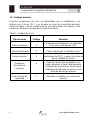 6
6
-
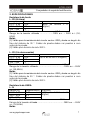 7
7
-
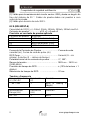 8
8
-
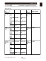 9
9
-
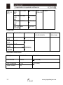 10
10
-
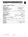 11
11
-
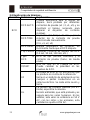 12
12
-
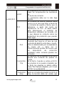 13
13
-
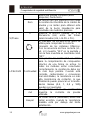 14
14
-
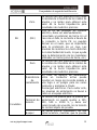 15
15
-
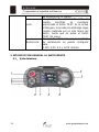 16
16
-
 17
17
-
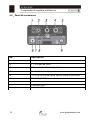 18
18
-
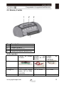 19
19
-
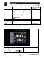 20
20
-
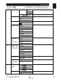 21
21
-
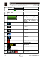 22
22
-
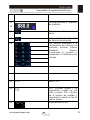 23
23
-
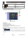 24
24
-
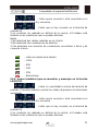 25
25
-
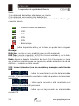 26
26
-
 27
27
-
 28
28
-
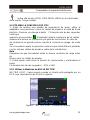 29
29
-
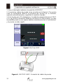 30
30
-
 31
31
-
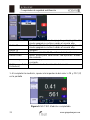 32
32
-
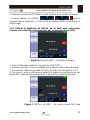 33
33
-
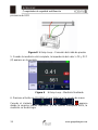 34
34
-
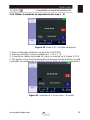 35
35
-
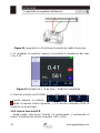 36
36
-
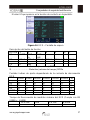 37
37
-
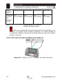 38
38
-
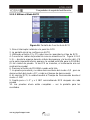 39
39
-
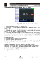 40
40
-
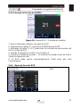 41
41
-
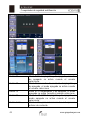 42
42
-
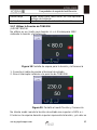 43
43
-
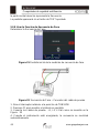 44
44
-
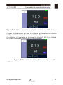 45
45
-
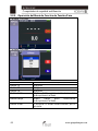 46
46
-
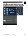 47
47
-
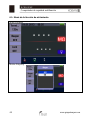 48
48
-
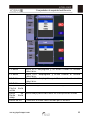 49
49
-
 50
50
-
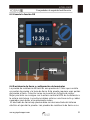 51
51
-
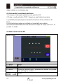 52
52
-
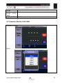 53
53
-
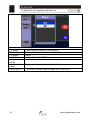 54
54
-
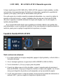 55
55
-
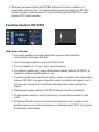 56
56
-
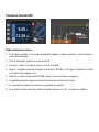 57
57
-
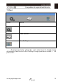 58
58
-
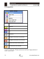 59
59
-
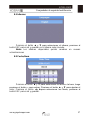 60
60
-
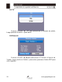 61
61
-
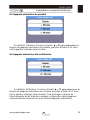 62
62
-
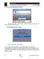 63
63
-
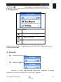 64
64
-
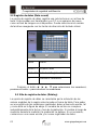 65
65
-
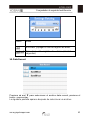 66
66
-
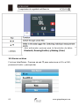 67
67
-
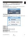 68
68
-
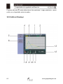 69
69
-
 70
70
-
 71
71
-
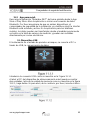 72
72
-
 73
73
-
 74
74
-
 75
75
-
 76
76
-
 77
77
-
 78
78
-
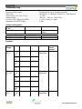 79
79
-
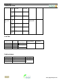 80
80
-
 81
81
-
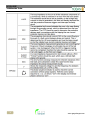 82
82
-
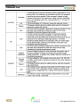 83
83
-
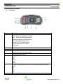 84
84
-
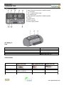 85
85
-
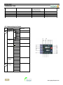 86
86
-
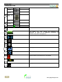 87
87
-
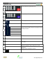 88
88
-
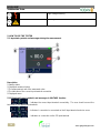 89
89
-
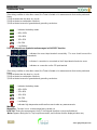 90
90
-
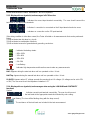 91
91
-
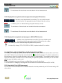 92
92
-
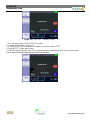 93
93
-
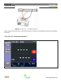 94
94
-
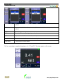 95
95
-
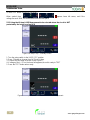 96
96
-
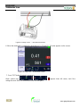 97
97
-
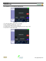 98
98
-
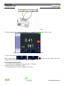 99
99
-
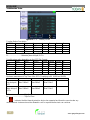 100
100
-
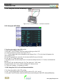 101
101
-
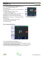 102
102
-
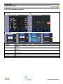 103
103
-
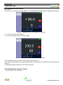 104
104
-
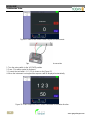 105
105
-
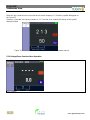 106
106
-
 107
107
-
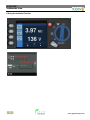 108
108
-
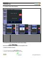 109
109
-
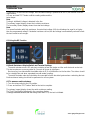 110
110
-
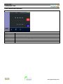 111
111
-
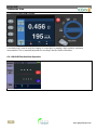 112
112
-
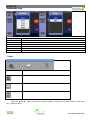 113
113
-
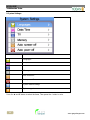 114
114
-
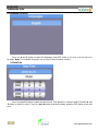 115
115
-
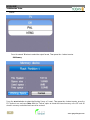 116
116
-
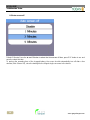 117
117
-
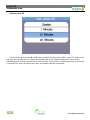 118
118
-
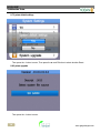 119
119
-
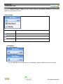 120
120
-
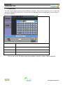 121
121
-
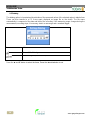 122
122
-
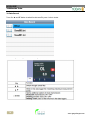 123
123
-
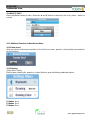 124
124
-
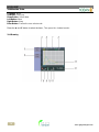 125
125
-
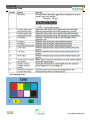 126
126
-
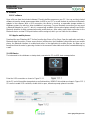 127
127
-
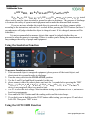 128
128
-
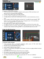 129
129
-
 130
130


koban KIT AUDITOR El manual del propietario
- Categoría
- Medir, probar
- Tipo
- El manual del propietario
- Este manual también es adecuado para
en otros idiomas
- English: koban KIT AUDITOR Owner's manual
Artículos relacionados
-
koban KMD-03 El manual del propietario
-
-
-
-
-
-
-