
KOS1020A
20221007
DISEÑOS Y TECNOLOGÍA, S.A.
Xarol, 6B P.I. Les Guixeres
08915 Badalona (Barcelona) - Spain
Tel. +34 933 394 758
Fax +34 934 903 145
Email: comercial@ditel.es ; web: www.ditel.es
ESPAÑOL
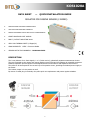
AISLADOR PARA CAPTADOR PASIVO (2 HILOS)
FRANÇAIS
ISOLATEUR POUR CAPTEUR PASSIF (2 FILS)
ENGLISH
ISOLATOR FOR PASSIVE SENSOR (2 WIRES)
GUIA RÁPIDA DE INSTALACIÓN .............................................. 02/03
GUIDE D'INSTALLATION RAPIDE ............................................. 04/05
QUICK INSTALLATION GUIDE ................................................. 06/07
DOWNLOAD
USER MANUAL

2
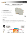
NO NECESITA ALIMENTACIÓN AUXILIAR
MUY ALTA PRECISIÓN Y LINEALIDAD
PROTEGIDO CONTRA SOBREINTENSIDADES
A LA ENTRADA Y LA SALIDA
GRAN AHORRO DE ESPACIO Y COSTE
AISLAMIENTO ENTRADA / SALIDA 3000V
MUY BAJA DERIVA TÉRMICA (≤25ppm/ºC)
ALTA FIABILIDAD MTBF > 500.000 HORAS
VERSION CON DOS CANALES : KOS1020A-DUAL
DESCRIPCIÓN
Los aisladores de 2 vías de señales 4-20mA, de 1 o 2 (versión DUAL), separan galvánicamente circuitos de
medición.
Están protegidos en sus entradas y salidas contra sobrecorrientes y sobretensiones por protectores rearmables.
La separación galvánica protege de la destrucción por sobretensión y de las interferencias inductivas y
capacitivas
Permiten ser interceptados en el bucle de corriente del captador pasivo, proporcionando la alimentación aislada
al captador.
La salida del aislador es pasiva a 2 hilos también. Mediante bornas enchufables codificadas, permiten el
cambio rápido de módulos y protegen ante equivocaciones.
KOS1020A
DATA SHEET — GUIA RÁPIDA DE INSTALACIÓN
AISLADOR PARA CAPTADOR PASIVO (2 HILOS)

3
20230509
DISEÑOS Y TECNOLOGÍA, S.A.
Xarol, 6B P.I. Les Guixeres
08915 Badalona (Barcelona) - Spain
Tel. +34 933 394 758
Fax +34 934 903 145
Email: comercial@ditel.es ; web: www.ditel.es
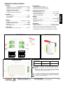
ESPECIFICACIONES TÉCNICAS
ENTRADA
Intensidad ……………………… 4-20mA (Captador pasivo 2 hilos)
Impedancia de entrada (con protección)………………………220Ω
Impedancia de entrada (sin protección)……………………….150Ω
Protegida contra sobrecorrientes……………………... max 500mA
Limitación corriente de entrada ……………………………….. 40mA
Protegida contra inversión de polaridad
PRECISIÓN
Máximo error global ……………………………………………... 0.05%
Error de linealidad ……………………………………………….. <0.03%
Deriva térmica …...…………………………………………..... 0.5µA/ºC
SALIDA
Intensidad ……………………………………… 4-20mA (pasivo 2 hilos)
Capacidad de carga típica (24V) …………………………………..800Ω
Capacidad de carga típica (12V) …………………………………..200Ω
Máxima carga……………………………………………… 1100Ω (30VDC)
Limitación de corriente ………………...……………….…………..25 mA
AISLAMIENTO
Tensión de aislamiento entrada / salida ……………….... 3000VAC
ALIMENTACIÓN
No necesita alimentación auxiliar
Se alimenta por el bucle de salida (24V)
Suministra excitación al bucle de entrada
CONDICIONES AMBIENTALES
Temperatura trabajo ……………………………………………. -25ºC ÷ 70ºC
Temperatura almacenamiento ………………………….. -50ºC ÷ +105ºC
Tiempo de calentamiento …...………………………………….. 5 minutos
Coeficiente de temperatura ……………………………………... 35ppm / ºC
FORMATO
Protección ............................................................................ IP20
Material……………………………………………………………...Poliamida PA6.6
Peso (Canal 1 / Canal 2).……………………………………………………….60g
Combustibilidad según UL ........................................................ V0
Montaje ................................................................... rail EN50022
CONEXIONES
Bornes por tornillo M3 .................................. par de apriete 0.5Nm
Cable de conexión ............................................ ≤2.5mm² (12AWG)
Protección contra equivocación mediante bornas codificadas.
Configuraciones y recalibraciones sin desconectar y sin soltar
del raíl mediante acceso frontal con tapa abatible con protección.
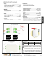
DIMENSIONES
CONEXIONADO
Directivas EMC 2014/30/EU LVD 2014/35/EU
Normas EN 61000-6-2
EN 61000-6-3 EN 61010-1
Conformidad CE .
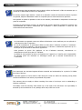
ATENCIÓN: Si este instrumento no se instala y utiliza de acuerdo con estas
instrucciones, la protección que brinda contra riesgos puede verse
afectada
Para cumplir con los requisitos de la norma EN 61010-1, donde la unidad está
permanentemente conectada a la fuente de alimentación principal, es obligatorio
instalar un dispositivo de corte de circuito fácilmente accesible para el operador y
claramente marcado como dispositivo de desconexión.
6...1
7 6 5 4 3 2 1
ENTRADA 1
PIN 1 + EXC
PIN 2 - IN1
SALIDA 1
PIN 5 +24V
PIN 6 - OUT1
De acuerdo con la Directiva 2012/19 / UE, no puede desecharlo al final
de su vida útil como basura municipal sin clasificar. Puede devolverlo,
sin ningún costo, al lugar donde fue adquirido para proceder a su
tratamiento y reciclaje controlados.
MONTAJE EN RAIL
ENTRADA 2 (DUAL)
PIN 3 + EXC
PIN 4 - IN2
SALIDA 2 (DUAL)
PIN 7 +24V
PIN 8 - OUT2
ESPAÑOL

4
N'A PAS BESOIN D'ALIMENTATION AUXILIAIRE
TRÈS HAUTE PRÉCISION ET LINÉARITÉ
PROTÉGÉ CONTRE LES SURINTENSITÉS
À L'ENTRÉE ET À LA SORTIE
GRANDES ÉCONOMIES D'ESPACE ET DE COÛTS
ISOLEMENT ENTRÉE / SORTIE 3000V
TRÈS FAIBLE DÉRIVE THERMIQUE (≤25ppm/ºC)
HAUTE FIABILITÉ MTBF > 500.000 HEURES
VERSION À DEUX CANAUX : KOS1020A-DUAL
DESCRIPTION
Isolateurs 2 voies pour signaux 4-20mA, 1 ou 2 (version DUAL), circuits de mesure galvaniquement séparés.
Ils sont protégés à leurs entrées et sorties contre les surintensités et les surtensions par des protecteurs
réarmables.
La séparation galvanique protège contre la destruction par surtension et les interférences inductives et
capacitives
Ils permettent d'être interceptés dans la boucle de courant du capteur passif, assurant l'alimentation isolée du
capteur.
La sortie de l'isolateur est également passive à 2 fils. Grâce à des bornes enfichables codées, ils permettent des
changements rapides de module et protègent contre les erreurs.
KOS1020A
DATA SHEET — GUIDE D'INSTALLATION RAPIDE
ISOLATEUR POUR CAPTEUR PASSIF (2 FILS)
CAPTEUR
PASSIVE SORTIE
PASSIVE
CAPTEUR
PASSIVE
2 fils

5
20230509
DISEÑOS Y TECNOLOGÍA, S.A.
Xarol, 6B P.I. Les Guixeres
08915 Badalona (Barcelona) - Spain
Tel. +34 933 394 758
Fax +34 934 903 145
Email: comercial@ditel.es ; web: www.ditel.es
SPÉCIFICATIONS TECHNIQUES
ENTRÉE
Courant ...………………………… 4-20mA (Capteur passive 2 fils)
Impédance d'entrée (avec protection) .………………………220Ω
Impédance d'entrée (sana protection) .……………………….150Ω
Protégé contre les surintensités ……………………... max 500mA
Limitation du courant d'entrée .……………………………….. 40mA
Protégé contre l'inversion de polarité
PRÉCISION
Erreur maximale globale ……………………………………... 0.05%
Erreur de linéarité ……………………………………………….. <0.03%
Dérive thermique ..…………………………………………..... 0.5µA/ºC
SORTIE
Courant ...……………………………………… 4-20mA (passive 2 fils)
Capacité de charge typique (24V) ………………………………..800Ω
Capacité de charge typique (12V) ………………………………..200Ω
Charge maximale ……………………………………… 1100Ω (30VDC)
Limitation de courant ………………...……………….…………..25 mA
ISOLEMENT
Tension d'isolement entrée/sortie ……..……………….... 3000VAC
ALIMENTATION
N'a pas besoin d'alimentation auxiliaire
Il est alimenté par la boucle de sortie (24V)
Fournit une excitation à la boucle d'entrée
ENVIRONNEMENTAL
Température fonctionnement ……………………………. -25ºC à +70ºC
Température de stockage ...…………………………...-50ºC à +105ºC
Temps de chauffage …..……...………………………………….. 5 minutes
Coéfficent de température ……………………………………...35ppm / ºC
FORMAT
Protection ………………………………………………………………………. IP20
Materiel ………………………………………………………...Polyamide PA6.6
Poids (Canal 1 / Canal 2) …………………………………………………….60g
Combustibilité selon UL……………………………………………………….. V0
Montage …………………………………………………………….. rail EN50022
CONNEXIONS
Bornes à vis M3 ………..……………………………………… Torque 0.5Nm
Câble de connexion .…………………………………...≤2.5mm² (12AWG)
Protection contre les erreurs au moyen de bornes codées.
Configurations et recalibrages sans déconnexion et sans lâcher prise
du rail par accès frontal avec couvercle rabattable avec protection.
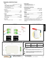
DIMENSIONS
RACCORDEMENT
6...1
7 6 5 4 3 2 1
ENTRÉE1
PIN 1 + EXC
PIN 2 - IN1
SORTIE 1
PIN 5 +24V
PIN 6 - OUT1
MONTAGE SUR RAIL
ENTRÉE 2 (DUAL)
PIN 3 + EXC
PIN 4 - IN2
SORTIE 2 (DUAL)
PIN 7 +24V
PIN 8 - OUT2
Directives EMC 2014/30/EU LVD 2014/35/EU
Normes EN 61000-6-2
EN 61000-6-3 EN 61010-1
Conformité CE .
ATTENTION : Si cet instrument n'est pas installé et utilisé conformément à
ces instructions, la protection qu'il offre contre les dangers peut être
altérée.
Pour répondre aux exigences de la norme EN 61010-1, où l'unité est connectée en
permanence à l'alimentation principale, il est obligatoire d'installer un dispositif de
coupure facilement accessible à l'opérateur et clairement identifié comme un
dispositif de déconnexion.
Selon la Directive 2012/19/UE, l’utilisateur ne pout se défaire de cet
appareil comme d’un residu urbain courant. Vous pouvez le restituer,
sans aucun coût, au lieu où il a eté acquis afin qu’il soit procédé à son
traitement et recyclage contrôlés.
FRANÇAIS

6
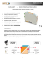
DOES NOT NEED AUXILIARY POWER SUPPLY
VERY HIGH PRECISION AND LINEARITY
PROTECTED AGAINST INPUT AND OUTPUT OVERCURRENTS
GREAT SPACE AND COST SAVING
INPUT / OUTPUT ISOLATION 3000V
VERY LOW THERMAL DRIFT (≤25ppm/ºC)
HIGH RELIABILITY MTBF > 500.000 HOURS
VERSION WITH TWO CHANNELS : KOS1020A-DUAL
DESCRIPTION
The 2-way isolators for 4-20mA signals, 1 or 2 (DUAL version), galvanically separate measurement circuits.
They are protected at their inputs and outputs against overcurrents and overvoltages by resettable protectors.
Galvanic separation protects against overvoltage destruction and inductive and capacitive interferences.
They allow to be intercepted in the current loop of the passive sensor, providing the isolated power supply to
the sensor.
The isolator output is 2-wire passive as well.
By means of coded plug-in terminals, they allow quick unit replacement and protect against mistakes.
KOS1020A
DATA SHEET — QUICK INSTALLATION GUIDE
ISOLATOR FOR PASSIVE SENSOR (2 WIRES)
PASSIVE
SENSOR
PASSIVE
OUTPUT
PASSIVE
SENSOR
2 WIRES

7
20230509
DISEÑOS Y TECNOLOGÍA, S.A.
Xarol, 6B P.I. Les Guixeres
08915 Badalona (Barcelona) - Spain
Tel. +34 933 394 758
Fax +34 934 903 145
Email: comercial@ditel.es ; web: www.ditel.es
TECHNICAL SPECIFICATIONS
INPUT
Current .………………..4-20mA (Passive sensor 2 wires)
Input impedance (with protection) …..………………………220Ω
Input impedance (without protection) ……………………….150Ω
Protected against overcurrents .……………………... max 500mA
Input current limitation ………..……………………………….. 40mA
Protected against reverse polarity
ACCURACY
Overall maximum error ………………………………………... 0.05%
Linearity error …...……………………………………………….. <0.03%
Thermal drift ..…...…………………………………………..... 0.5µA/ºC
OUTPUT
Current .……………………………………… 4-20mA (passive 2 wires)
Typical load capacity (24V) …….…………………………………..800Ω
Typical load capacity (12V) …….…………………………………..200Ω
Maximum load …………………………………………… 1100Ω (30VDC)
Current limitation …….………………...……………….…………..25 mA
ISOLATION
Isolation voltage input / output ..……..……………….... 3000VAC
POWER SUPPLY
Does not need auxiliary power
It is powered by the output loop (24V)
Supplies excitation to input loop
ENVIRONMENTAL CONDITIONS
Operating temperature ………………………………. –25ºC to +70ºC
Storage temperatura ….……………………………….-50ºC to +105ºC
Heating time …………...…...………………………………….. 5 minutes
Temperature coefficient ..…………………………………... 35ppm / ºC
FORMAT
Protection ………………………………………………………………….. IP20
Material ……………………………………………………...Polyamide PA6.6
Weight (1 Channel / 2 Channels) ...………………………………….60g
UL Combustibility ………….………………………………………………... V0
Mounting …………………………………………………………. rail EN50022
WIRING
Screw terminals M3 ………...……………………………... torque 0.5Nm
Connection cable ……………………………………..≤2.5mm² (12AWG)
Protection against mistakes by means of coded terminals.
Configurations and recalibrations without disconnecting and without
letting go of the rail through front access with hinged cover with
protection.
DIMENSIONS
WIRING
6...1
7 6 5 4 3 2 1
INPUT 1
PIN 1 + EXC
PIN 2 - IN1
OUTPUT 1
PIN 5 +24V
PIN 6 - OUT1
RAIL MOUNTING
INPUT 2 (DUAL)
PIN 3 + EXC
PIN 4 - IN2
OUTPUT 2 (DUAL)
PIN 7 +24V
PIN 8 - OUT2
Directives EMC 2014/30/EU LVD 2014/35/EU
Standarts EN 61000-6-2
EN 61000-6-3 EN 61010-1
CE Conformity.
ATTENTION: If this instrument is not installed and used in accordance with
these instructions, the protection it provides against hazards may be
impaired.
To meet the requirements of EN 61010-1, where the unit is permanently connected
to the main power supply, it is mandatory to install a circuit-breaking device easily
accessible to the operator and clearly marked as a disconnect device.
According to 2012/19/EU Directive, You cannot dispose of it at the end
of its lifetime as unsorted municipal waste. You can give it back,
without any cost, to the place where it was adquired to proceed to its
controlled treatment and recycling.
SINK SIN K
ENGLISH

8
20230509
DISEÑOS Y TECNOLOGÍA, S.A.
Xarol, 6B P.I. Les Guixeres
08915 Badalona (Barcelona) - Spain
Tel. +34 933 394 758
Fax +34 934 903 145
Email: comercial@ditel.es ; web: www.ditel.es
Los instrumentos están garantizados contra cualquier defecto de fabricación o fallo de materiales por un
periodo de 3 AÑOS desde la fecha de su adquisición.
En caso de observar algún defecto o avería en la utilización normal del instrumento durante el periodo
de garantía, diríjase al distribuidor donde fue comprado quien le dará instrucciones oportunas.
Esta garantía no podrá ser aplicada en caso de uso indebido, conexionado o manipulación erróneos por
parte del comprador.
El alcance de esta garantía se limita a la reparación del aparato declinando el fabricante cualquier otra
responsabilidad que pudiera reclamársele por incidencias o daños producidos a causa del mal
funcionamiento del instrumento.
GARANTÍA
Les instruments sont garantis contre tout défaut de fabrication ou de matériaux pour une période de
3 ANS depuis la date d´acquisition.
En cas de constatation d´un quelconque défaut où avarie dans l´utilisation normale de l´instrument
pendant la période de garantie, il est recommandé de s´adresser au distributeur auprès de qui il a
été acquis et qui donneras les instructions opportunes.
Cette garantie ne pourra être appliquée en cas d´utilisation anormale, raccordement ou
manipulations erronés de la part de l´utilisateur.
La validité de cette garantie se limite a la réparation de l´appareil et n´entraîne pas la responsabilité
du fabricant quant aux incidentes ou dommages causés par le mauvais fonctionnement de
l´instrument.
GARANTIE
The instruments are warranted against defective materials and workmanship for a period of 3 YEARS
from date of delivery.
If a product appears to have a defect or fails during the normal use within the warranty period, please
contact the distributor from which you purchased the product.
This warranty does not apply to defects resulting from action of the buyer such as mishandling or
improper interfacing.
The liability under this warranty shall extend only to the repair of the instrument. No responsibility is
assumed by the manufacturer for any damage which may result from its use.
WARRANTY
-
 1
1
-
 2
2
-
 3
3
-
 4
4
-
 5
5
-
 6
6
-
 7
7
-
 8
8


