AirLive POE-48TUv2 Guía de inicio rápido
- Categoría
- Adaptadores PoE
- Tipo
- Guía de inicio rápido

Declaration of Conformity
We, Manufacturer/Importer
Declare that the product
802.3af PoE Splitter with Switchable Output Power
AirLive POE-48TUv2
is in conformity with
In accordance with 2004/108/EC Directive and 1999/5 EC-R & TTE Directive
Clause
Manufacturer/Importer
Description
OvisLink Corp.
5F., NO.6, Lane 130, Min-Chuan Rd., Hsin-Tien Dist.,
New Taipei City 231, Taiwan
Important Notices:
Hardware:
Limits and methods of measurement of radio disturbance
characteristics of information technology equipment
Information Technology equipment-Immunity characteristics-Limits
and Methods of measurement
Safety for information technology equipment including electrical
business equipment
■
EN 55022:2010
■
EN 55024:2010
■
EN 60950-1:2006 +
A11:2009 +A12:2011
■
CE marking
Signature:
Name:Albert Yeh
Position/ Title : Vice President Place:Taiwan Date:2012/07/13
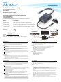
Installation Step:
1. Switch the voltage value of POE-48TUv2 to right value (5V, 9Vor12V) via the DIP Switch located on the
side. (Picture 1)
2. Choose the right size power jack for your device, then connect the jack to the POE-48TUv2 (Picture 2)
3. Connect "Power + Data In" port of POE-48TUv2 to the network device. Please make sure that LED is on.
4. Connect power jack of the network device to "Power Out" port of POE-48TUv2 via power cable, and
connect RJ-45 port of PD to "Data Out" port of POE-48TUv2.
5. Check whether the network device is on. If not, please make sure that power is on for DC Injector/POE
Switch.
1. Please set the POE-48TUv2 to the correct voltage first. You should set to the same voltage as your
network device. Setting the wrong voltage will damage the PoE device.
2. When switch to different voltage, POE-48TUv2 must be in powered-off status.
POE-48TUv2 has three connection ports, one LED indicator, and one dip switch for voltage
output switching.
Power + Data In port: It is a RJ-45 Ethernet port for receiving power and data from PSE (power
sourcing equipment). Connect the cable from DC Injector to this port.
Data Out port: It is a RJ-45 Ethernet port. Please connect this port to the Ethernet port of the
network device.
Power Out port: The Power Out port is for transmitting the power to the network device that is
powered by 5V, 9V or 12V.
Dip switch: It uses for switching voltage output. It provides 3 different voltage values: 5V, 9V and
12V. The default is 5V.
5V, 9V and 12V LED Indicators: The LED will on when switch voltage level.
Důležité:
Hardware:
Instalační kroky:
1. Nastavte správnou voltáž. (Obrázek 1)
2. Vyberte správný konektor (Obrázek 2)
3. Připojte "Power + Data In" port kabelem.
4. Připojte "Power Out" port.
5. Ujistěte se, že vše funguje.
1. Prosím, nastavte POE-48TUv2 na správnou voltáž - stejnou jako vyžaduje vaše síťové zařízení. Špatné
nastavení může způsobit poruchu.
2. Při změně voltáže musí být zařízení vypnuto..
POE-48TUv2 má 3 porty, 1 LED indikátor a 1dip switch na změnu výstupní voltáže.
Power + Data In port: Je síťový port pro příjem dat a elektrické energie.
Data Out port: Je port pro připojení síťového zařízení.
Power Out port: Je port s elektrickým výstupm 5V, 9V, 12V.
Dip switch:Slouží k přepínání výstupního napětí.
5V, 9V a 12V LED Indikátor výstupního napětí.
Wichtige Hinweise:
Hardware:
Installationsschritte:
1. Stellen Sie am POE-48TUv2 über den DIP Schalter die korrekte Spannung (5V, 9V oder 12V) ein. (Bild 1)
2. Wählen Sie die richtige Größe des Stromanschluß für Ihr Gerät, verbinden Sie es dann mit den
POE-48TUv2 (Bild 2)
3. Verbinden Sie die "Power + Data In" Anschlüsse des POE-48TUv2 mit Ihrem Netzwerkgerät. Stellen Sie
sicher, dass die LED leutet.
4. Verbinden Sie das Stromkabel Ihres Netzwerkgerätes mit dem "Power Out" Anschluß des POE-48TUv2
und verbinden den RJ-45 Anschluß des Netzwerkgerätes mit dem "Data Out" Anschluß des POE-48TUv2.
5. Prüfen Sie, ob das Netzwerkgerät eingeschaltet ist. Falls nicht, stellen Sie sicher dass der Strom am DC
Injektor/POE Switch anliegt.
1. Vor der Inbetriebnahme muss die korrekte Spannung am POE-48TUv2 eingestellt werden. Stellen Sie
unbedingt die richtige Stromspannung für Ihr Netzwerkgerät ein. Eine falsche Einstellung wird das Gerät
beschädigen!
2. Der POE-48TUv2 muß ausgeschaltet sein, wenn die Spannung eingestellt wird.
Der POE-48TUv2 besitzt drei Anschlüsse, eine LED Anzeige und einen DIP Schalter zur
Einstellung der Spannung.
Power + Data In Anschluß: dies ist der RJ-45 Ethernet Anschluß um Strom und Daten zu erhalten.
Verbinden Sie das Kabel des DC Injektors bzw. PoE Switches mit diesem Anschluß.
Data Out Anschluß: dies ist der RJ-45 Ethernet Daten-Anschluß. Bitte verbinden Sie Ihr
Netzwerkgerät mit diesem Anschluß.
Power Out Anschluß: Der Power Out Anschluß bietet die gewählte Ausgangsspannung 5V, 9V
oder 12V für Ihr Netzwerkgerät.
DIP Schalter: Er wird genutzt, um die Ausgangsspannung zu definieren. Sie können aus drei
unterschiedlichen Stromstärken wählen: 5V, 9V und 12V. Die Voreinstellung ist 5V.
5V, 9V und 12V LED Anzeige: Die LED leutet, wenn die Spannung gewechselt wird.
Importante:
Hardware:
Pasos de instalación:
1. Fijar el voltaje del POE-48TUv2 al valor correcto (5V, 9V o 12V) por medio del DIP Switch (Figura 1)
2. Elegir el tamaño del corriente para su dispositivo y luego conectarlo al POE-48TUv2 (Figura 2)
3. Conectar el "Power + Data In" al dispositivo de conexión de red y asegurar que el indicador LED este
encendido
4. Conectar la corriente al dispositivo de red al puerto "Power Out" del POE-48TUv2 por medio del cable de
corriente y conectar el puerto RJ-45 del PD al "Data Out" del POE-48TUv2
5. Asegurar de que el dispositivo de red esté encendido. Si no, verificar si la corriente del DC o POE
Switch está encendido
1. Fijar el POE-48TUv2 al voltaje correcto. Fije el mismo voltaje que el dispositivo de conexión de red ya
que un error en el voltaje dañará el PoE.
2. Apague el POE-48TUv2 antes de cambiar el voltaje
POE-48TUv2 tiene 3 puertos de conexión, 1 indicador LED, 1 dip switch para el intercambio de la
salida de voltaje
Power + Data In: es un puerto RJ-45 que puede recibir corriente y datos desde el PSE (power
sourcing equipment). Conectar el cable desde el DC a este puerto
Data Out: es un puerto RJ-45. Conectar este puerto al puerto Ethernet del dispositivo de red
Power Out: la salida de corriente es para transmitir la corriente al dispositivo de red de 5V, 9V o
12V
Dip switch: se usa para la salida de voltaje de 5V (default), 9V y 12V.
Indicadores LED de 5V, 9V y 12V. El LED se encenderá cuando use el voltaje del switch
P1
Česky
CZ
English
EN
Español
ES
Deutsch
DE
DC 12V
LAN1 LAN2
ANT.
Reset
PoE Switch
Wireless AP
(Picture 1)
(Picture 2)
LAN
PoE Cable
DATA + Power
POE-48TUv2
PoE Splitter
DC Power Cord
DATA
Power
PoE Switch
Web Smart
POE-FSH2442G
PWR
SYS
PWR MAX
2 4 6 8 10 12 14 16 18 20 22 24
13 5 7 911131719212325
Link/Act
100Mbps
PoE
1000Mbps
100Mbps
Link/Act
25 26
25 26
27 28
RESET
OK
FAN
Fail
1
3
5
7
2468
9
11
13 15
10 12 14 1 6
17
19
21
23
18 20 22 24 26 26 28
Mini-GBIC
25
25
27
1000BASE-TMini-GBIC
Link/Act
100Mbps
PoE
5V
5V
5V
9V
9V
9V
12V
12V
12V
5V5V5V 9V9V9V 12V12V12V
Set the POE-48TUv2 to the correct
voltage: 5V, 9V or 12V
La página se está cargando...
Transcripción de documentos
Declaration of Conformity We, Manufacturer/Importer OvisLink Corp. 5F., NO.6, Lane 130, Min-Chuan Rd., Hsin-Tien Dist., New Taipei City 231, Taiwan Declare that the product 802.3af PoE Splitter with Switchable Output Power AirLive POE-48TUv2 is in conformity with In accordance with 2004/108/EC Directive and 1999/5 EC-R & TTE Directive Clause Description ■ EN 55022:2010 Limits and methods of measurement of radio disturbance characteristics of information technology equipment ■ EN 55024:2010 Information Technology equipment-Immunity characteristics-Limits and Methods of measurement ■ EN 60950-1:2006 + A11:2009 +A12:2011 Safety for information technology equipment including electrical business equipment (Picture 1) ■ CE marking Set the POE-48TUv2 to the correct voltage: 5V, 9V or 12V Manufacturer/Importer Wireless AP PoE Switch 100Mbps OK FAN POE-FSH2442G 1 3 5 7 9 11 13 15 17 19 2 4 6 8 10 12 14 16 18 20 21 23 25 Mini-GBIC 25 24 26 26 1000BASE-T 27 5V 9V 12V Web Smart Link/Act PWR MAX PoE Switch 25 26 25 26 Mini-GBIC PoE 1 3 5 7 9 11 13 17 19 21 23 25 2 4 6 8 10 12 14 16 18 20 22 24 Fail DC 12V 1000Mbps 100Mbps Link/Act PWR Reset LAN1 LAN2 ANT. 100Mbps RESET Link/Act 27 28 LAN 28 PoE Cable Power DATA 9V DATA + Power Date:2012/07/13 5V Place:Taiwan 22 12V Name:Albert Yeh Position/ Title : Vice President PoE SYS Signature: DC Power Cord POE-48TUv2 (Picture 2) PoE Splitter EN English Important Notices: 1. Please set the POE-48TUv2 to the correct voltage first. You should set to the same voltage as your network device. Setting the wrong voltage will damage the PoE device. 2. When switch to different voltage, POE-48TUv2 must be in powered-off status. Hardware: POE-48TUv2 has three connection ports, one LED indicator, and one dip switch for voltage output switching. Power + Data In port: It is a RJ-45 Ethernet port for receiving power and data from PSE (power sourcing equipment). Connect the cable from DC Injector to this port. Data Out port: It is a RJ-45 Ethernet port. Please connect this port to the Ethernet port of the network device. Power Out port: The Power Out port is for transmitting the power to the network device that is powered by 5V, 9V or 12V. Dip switch: It uses for switching voltage output. It provides 3 different voltage values: 5V, 9V and 12V. The default is 5V. 5V, 9V and 12V LED Indicators: The LED will on when switch voltage level. Installation Step: 1. Switch the voltage value of POE-48TUv2 to right value (5V, 9Vor12V) via the DIP Switch located on the side. (Picture 1) 2. Choose the right size power jack for your device, then connect the jack to the POE-48TUv2 (Picture 2) 3. Connect "Power + Data In" port of POE-48TUv2 to the network device. Please make sure that LED is on. 4. Connect power jack of the network device to "Power Out" port of POE-48TUv2 via power cable, and connect RJ-45 port of PD to "Data Out" port of POE-48TUv2. 5. Check whether the network device is on. If not, please make sure that power is on for DC Injector/POE Switch. DE Deutsch Wichtige Hinweise: 1. Vor der Inbetriebnahme muss die korrekte Spannung am POE-48TUv2 eingestellt werden. Stellen Sie unbedingt die richtige Stromspannung für Ihr Netzwerkgerät ein. Eine falsche Einstellung wird das Gerät beschädigen! 2. Der POE-48TUv2 muß ausgeschaltet sein, wenn die Spannung eingestellt wird. Hardware: Der POE-48TUv2 besitzt drei Anschlüsse, eine LED Anzeige und einen DIP Schalter zur Einstellung der Spannung. Power + Data In Anschluß: dies ist der RJ-45 Ethernet Anschluß um Strom und Daten zu erhalten. Verbinden Sie das Kabel des DC Injektors bzw. PoE Switches mit diesem Anschluß. Data Out Anschluß: dies ist der RJ-45 Ethernet Daten-Anschluß. Bitte verbinden Sie Ihr Netzwerkgerät mit diesem Anschluß. Power Out Anschluß: Der Power Out Anschluß bietet die gewählte Ausgangsspannung 5V, 9V oder 12V für Ihr Netzwerkgerät. DIP Schalter: Er wird genutzt, um die Ausgangsspannung zu definieren. Sie können aus drei unterschiedlichen Stromstärken wählen: 5V, 9V und 12V. Die Voreinstellung ist 5V. 5V, 9V und 12V LED Anzeige: Die LED leutet, wenn die Spannung gewechselt wird. Installationsschritte: 1. Stellen Sie am POE-48TUv2 über den DIP Schalter die korrekte Spannung (5V, 9V oder 12V) ein. (Bild 1) 2. Wählen Sie die richtige Größe des Stromanschluß für Ihr Gerät, verbinden Sie es dann mit den POE-48TUv2 (Bild 2) 3. Verbinden Sie die "Power + Data In" Anschlüsse des POE-48TUv2 mit Ihrem Netzwerkgerät. Stellen Sie sicher, dass die LED leutet. 4. Verbinden Sie das Stromkabel Ihres Netzwerkgerätes mit dem "Power Out" Anschluß des POE-48TUv2 und verbinden den RJ-45 Anschluß des Netzwerkgerätes mit dem "Data Out" Anschluß des POE-48TUv2. 5. Prüfen Sie, ob das Netzwerkgerät eingeschaltet ist. Falls nicht, stellen Sie sicher dass der Strom am DC Injektor/POE Switch anliegt. CZ Česky Důležité: 1. Prosím, nastavte POE-48TUv2 na správnou voltáž - stejnou jako vyžaduje vaše síťové zařízení. Špatné nastavení může způsobit poruchu. 2. Při změně voltáže musí být zařízení vypnuto.. Hardware: POE-48TUv2 má 3 porty, 1 LED indikátor a 1dip switch na změnu výstupní voltáže. Power + Data In port: Je síťový port pro příjem dat a elektrické energie. Data Out port: Je port pro připojení síťového zařízení. Power Out port: Je port s elektrickým výstupm 5V, 9V, 12V. Dip switch:Slouží k přepínání výstupního napětí. 5V, 9V a 12V LED Indikátor výstupního napětí. Instalační kroky: 1. Nastavte správnou voltáž. (Obrázek 1) 2. Vyberte správný konektor (Obrázek 2) 3. Připojte "Power + Data In" port kabelem. 4. Připojte "Power Out" port. 5. Ujistěte se, že vše funguje. ES Español Importante: 1. Fijar el POE-48TUv2 al voltaje correcto. Fije el mismo voltaje que el dispositivo de conexión de red ya que un error en el voltaje dañará el PoE. 2. Apague el POE-48TUv2 antes de cambiar el voltaje Hardware: POE-48TUv2 tiene 3 puertos de conexión, 1 indicador LED, 1 dip switch para el intercambio de la salida de voltaje Power + Data In: es un puerto RJ-45 que puede recibir corriente y datos desde el PSE (power sourcing equipment). Conectar el cable desde el DC a este puerto Data Out: es un puerto RJ-45. Conectar este puerto al puerto Ethernet del dispositivo de red Power Out: la salida de corriente es para transmitir la corriente al dispositivo de red de 5V, 9V o 12V Dip switch: se usa para la salida de voltaje de 5V (default), 9V y 12V. Indicadores LED de 5V, 9V y 12V. El LED se encenderá cuando use el voltaje del switch Pasos de instalación: 1. Fijar el voltaje del POE-48TUv2 al valor correcto (5V, 9V o 12V) por medio del DIP Switch (Figura 1) 2. Elegir el tamaño del corriente para su dispositivo y luego conectarlo al POE-48TUv2 (Figura 2) 3. Conectar el "Power + Data In" al dispositivo de conexión de red y asegurar que el indicador LED este encendido 4. Conectar la corriente al dispositivo de red al puerto "Power Out" del POE-48TUv2 por medio del cable de corriente y conectar el puerto RJ-45 del PD al "Data Out" del POE-48TUv2 5. Asegurar de que el dispositivo de red esté encendido. Si no, verificar si la corriente del DC o POE Switch está encendido P1-
 1
1
-
 2
2


AirLive POE-48TUv2 Guía de inicio rápido
- Categoría
- Adaptadores PoE
- Tipo
- Guía de inicio rápido
en otros idiomas
- English: AirLive POE-48TUv2 Quick start guide
- Deutsch: AirLive POE-48TUv2 Schnellstartanleitung
- русский: AirLive POE-48TUv2 Инструкция по началу работы
- português: AirLive POE-48TUv2 Guia rápido
- slovenčina: AirLive POE-48TUv2 Stručná príručka spustenia
- polski: AirLive POE-48TUv2 Skrócona instrukcja obsługi
Artículos relacionados
Otros documentos
-
Repotec RP-PEG048IB El manual del propietario
-
Air Live POE-GSH504ATi Quick Setup Manual
-
Trendnet TI-SG104 Quick Installation Guide
-
Grandstream GWN7602 Quick Installation Manual
-
Grandstream GDS3710 Quick Installation Guide
-
Grandstream GDS3705 Quick Installation Guide
-
LevelOne WAP-6201 Quick Installation Manual
-
Trendnet TPE-112GS Ficha de datos
-
Grandstream GSC3570 Guía de instalación
-