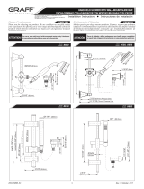
Graff Aqua-Sense Installation Instructions Manual
- Categoría
- Artículos sanitarios
- Tipo
- Installation Instructions Manual

1
Dear Customer Estimado Cliente
Thank you for selecting our product. We are confident we can fully satisfy Muchas gracias por elegir nuestro producto. Estamos seguros que podemos
your expectations by offering you a wide range of technologically advanced satisfacer completamente sus expectativas ofreciéndole una amplia variedad
products which directly result from our many years of experience in faucet de productos tecnológicamente avanzados que resultan direct
amente de
and fitting production. muchos años de experiencia en grifos y su producción apropiada.
ENGLISH
~
ESPANOL
This faucet complies with NSF61/9, ASME/ANSI A112.18.1
and CSA B 125 Standards.
Este grifo se encuentra conforme con losestandares de NSF61/9,
de ASME/ANSI A112.18.1 y de CSA B 125.
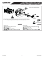
Installation Instructions Instrucciones de Instalación
For care, use soft towel with soap and water only! Under no
circumstances should you use any chemicals.
ATTENTION!
ATENCIÓN!
Utilice solamente una toalla suave con jabón y agua.
Bajo ninguna circunstancia use productos químicos
IOG 5032.00
Model
Modelo
AQUA-SENSE
ELECTRONIC THERMOSTATIC SYSTEM
SISTEMA TERMOSTÁTICO ELECTRÓNICO
Rev. 2 May 2017

2
This faucet complies with NSF61/9, ASME/ANSI A112.18.1
and CSA B 125 Standards.
Este grifo se encuentra conforme con losestandares de NSF61/9,
de ASME/ANSI A112.18.1 y de CSA B 125.
Installation Instructions Instrucciones de Instalación
ELECTRONIC THERMOSTATIC SYSTEM
SISTEMA TERMOSTÁTICO ELECTRÓNICO
IOG 5032.00
1
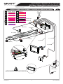
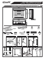
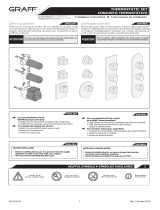
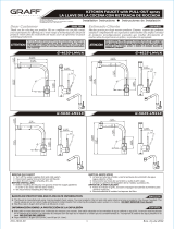
ASSEMBLY DIAGRAM ESQUEMA DE MONTAJE
Rev. 2 May 2017
4-1/16”
(103mm)
6-7/16”(163mm)
5-7/8”
(150mm)
8-1/8”(207mm)
Ø1-7/8”
(Ø48mm)
15-5/16” (388mm)
12-1/8”(308mm)
5-1/8”
(130mm)
3-1/4”
(82,5mm)
3-1/4”
(82,5mm)
5-1/8”
(130mm)
3-1/4”
(82,5mm)
16-1/4” (512,5mm)
3-1/4”
(82,5mm)
16-1/4” (512,5mm)
22-1/2” (572mm)
16-3/4” (425mm)
3-1/4”
(82,5mm)
5-1/8”
(130mm)
5-1/8”
(130mm)
Ø2-3/4”
(Ø70mm)
Ø7/8”
(Ø22mm)
16-5/16” (415mm)
61” (1550mm)
43-5/16” (1100mm)
Control-Box
Box de control
Multifunction Shower Head- Ceiling Mtd./Rain/LED Light/WaterFall/.
Alcachofa de ducha multifunción a tech-Iluvia/LED/cascada.
Set of 4 speakers
Set de 4 altavoces
Control Touch Panel
Panel de control touch screen
Hand Shower
Ducha de mano
Body spray
Alcachofa de ducha lateral
USB-Port
Puerta-USB
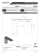
Size and spacing of assembly openings.
Tamaños y distribución de los orificios de montaje.
Location and number of the receivers are discretionary – suggested. The distance between the particular receivers is determined by the dimensions of the devices
and the length of the service lines
La ubicación y el número de los recipientes son discrecionales - sugeridos. La distancia entre los distintos recipientes viene determinada por las dimensiones de los
equipos y la longitud de las líneas de servicio
Wall-mounted bathtub spout
Caño bañera de pared

3
This faucet complies with NSF61/9, ASME/ANSI A112.18.1
and CSA B 125 Standards.
Este grifo se encuentra conforme con losestandares de NSF61/9,
de ASME/ANSI A112.18.1 y de CSA B 125.
Installation Instructions Instrucciones de Instalación
ELECTRONIC THERMOSTATIC SYSTEM
SISTEMA TERMOSTÁTICO ELECTRÓNICO
IOG 5032.00
2
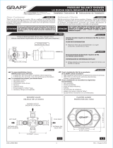
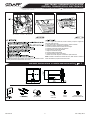
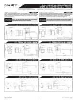
INSTALLATION OF THE CONTROL-BOX MONTAJE DEL BLOQUE FUNCIONAL
Rev. 2 May 2018
1 2
3
G3/4”
12-1/8”
(308mm)
15-5/16”
(388mm)
4-15/16”
(126mm)
NOTE! While designing the installation of the Control-Box, the installation method
enabling service access should be taken into account .
NOTA! Al diseñar la instalación de la Caja de Control, debe tenerse en cuenta el
método de instalación que permita el acceso al servicio.
Control-Box.
Control-Box

Seal the screw connections.
Selle las uniones atornilladas.
Failure to use the filters on cold and hot water inlets to the Control-Box may result in the breach of the terms of warranty. The filters need to
be cleaned regularly every 2–3 months, depending on the quality of water in the system.
Si no se utilizan los filtros en las entradas de agua fría y caliente de la Caja de Control, se pueden incumplir los términos de la garantía. Se
deben limpiar los filtros regularmente cada 2-3 meses, dependiendo de la calidad del agua en el sistema.
Block with a Key while screwing / unscrewing
Bloquear con una llave mientras atornilla / desatornilla
COLD
HOT
4
This faucet complies with NSF61/9, ASME/ANSI A112.18.1
and CSA B 125 Standards.
Este grifo se encuentra conforme con losestandares de NSF61/9,
de ASME/ANSI A112.18.1 y de CSA B 125.
Installation Instructions Instrucciones de Instalación
ELECTRONIC THERMOSTATIC SYSTEM
SISTEMA TERMOSTÁTICO ELECTRÓNICO
IOG 5032.00
Rev. 2 May 2018
2. Remove the wye strainer nuts.
4. Remove the contamination under running water.
2. Retire las tuercas del filtro de estrella.
4. Elimine la suciedad bajo el agua corriente.
Control-Box.

5
This faucet complies with NSF61/9, ASME/ANSI A112.18.1
and CSA B 125 Standards.
Este grifo se encuentra conforme con losestandares de NSF61/9,
de ASME/ANSI A112.18.1 y de CSA B 125.
Installation Instructions Instrucciones de Instalación
ELECTRONIC THERMOSTATIC SYSTEM
SISTEMA TERMOSTÁTICO ELECTRÓNICO
IOG 5032.00
Rev. 2 May 2018
3
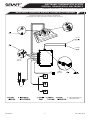
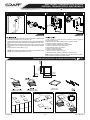
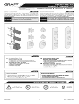
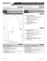
WIRING CONNECTION DIAGRAM • ESQUEMA DE CONEXIÓN DE CABLES
47-1/4”(1200mm)
59-1/16”(1500mm)
9-7/8”(250mm)
9-7/8”(250mm)
29-1/2”(750mm)
~197”(5000mm)
~197”(5000mm)
~197”(5000mm)
~197”(5000mm)
~197”(5000mm)
AUDIO IN - USB port
ANTENNA
AUDIO OUT - right
AUDIO OUT - left
LED
DISPLAY
UPDATE
POWER
SPEAKER CONNECTION - right
K
K
K
J
J
J
J
H
F
H
F
F
H
D
D
D
B
B
C
B
I
I
A
A
K
J
H
F
D
I
A
B B
I I
D D
H H
F F
E E
A A
C C
J J
K K
A
G
E
K
F
H
D
B
I
A
E
DISPLAY CONNECTION
C
SPEAKER CONNECTION - left
G G
G
The feeder must be installed in the distance of 0.6 m from the shower cabin.
El alimentador debe instalarse a una distancia de 0,6 m de la cabina de ducha.
110V

6
This faucet complies with NSF61/9, ASME/ANSI A112.18.1
and CSA B 125 Standards.
Este grifo se encuentra conforme con losestandares de NSF61/9,
de ASME/ANSI A112.18.1 y de CSA B 125.
Installation Instructions Instrucciones de Instalación
ELECTRONIC THERMOSTATIC SYSTEM
SISTEMA TERMOSTÁTICO ELECTRÓNICO
IOG 5032.00
Rev. 2 May 2018
4
G1/2”
G1/2”
Colador
Colador
4
5
2
1
3
1
6
2
3
5
4
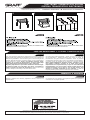
WATER SUPPLY CONNECTION DIAGRAM • SCHEMA DI COLLEGAMENTO
Hot water
Cold water
2
1
3
5
4
5
6
The connection configuration may vary, depending on the selected set.
La configuración de la conexión puede variar en función del conjunto de selección.
1
3
2
5
6
Caño bañera de pared
Wall-mounted bathtub spout
Colador
Half-union
Media unión
Half-union
Media unión

7
This faucet complies with NSF61/9, ASME/ANSI A112.18.1
and CSA B 125 Standards.
Este grifo se encuentra conforme con losestandares de NSF61/9,
de ASME/ANSI A112.18.1 y de CSA B 125.
Installation Instructions Instrucciones de Instalación
ELECTRONIC THERMOSTATIC SYSTEM
SISTEMA TERMOSTÁTICO ELECTRÓNICO
IOG 5032.00
Rev. 2 May 2018
5
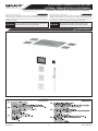
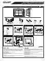
CONTROL TOUCH PANEL INSTALLATION
PANEL DE CONTROL TOUCH SCREEN INSTALACIÓN
1
2
3
4
5
6
7
55-1/8” - 61”
1400mm - 1550mm
1
1
min. 300mm
11-13/16”
Screw holder
Tornillo de fijación
Washer
Arandela
8-1/8"
207mm
5-15/16"
150mm
3/4"
19mm
1-7/8"
48mm
Mounting box
Caja de montaje
Screws
Tornillos
1.
2.
4.
5.
6.
3.
Prepare the recess in the plumbing wall at an appropriate height – the suggested
installation height for the touch panel is 55-1/8” (1400 mm) ÷61” (1550 mm).Place the
recess so that the cables can be freely drawn out for at least 11–15/16” (300 mm).
While placing the mounting box in the recess, pull the electrical cables through the
opening in the fixture.
Check if the mounting box is in horizontal position.
Fix the mounting box.
Connect the control panel cables.
Put the control panel into the mounting box and fix it with screws using the enclosed
Allen wrench.
NOTE! While designing the installation of the control panel, the installation method
enabling service access should be considered.
1.
2.
4.
5.
6.
3.
Prepare el hueco en la pared de plomería a una altura adecuada - la altura de
instalación sugerida para el panel táctil es de 55-1/8" (1400 mm) ÷ 61" (1550 mm).
Haga el hueco de manera que los cables puedan extenderse libremente durante al
menos 11-15/16" (300 mm).
Mientras coloca la caja de montaje en el hueco, pase los cables eléctricos a través
de la abertura de la unidad.
Compruebe que la caja de montaje esté en posición horizontal.
Fije la caja de montaje.
Conecte los cables del panel de control.
Coloque el panel de control en la caja de montaje y fíjelo con tornillos utilizando la
llave Allen suministrada.
NOTA! Al diseñar la instalación del panel de control, debe tenerse en cuenta el
método de instalación que permita el acceso al servicio.

8
This faucet complies with NSF61/9, ASME/ANSI A112.18.1
and CSA B 125 Standards.
Este grifo se encuentra conforme con losestandares de NSF61/9,
de ASME/ANSI A112.18.1 y de CSA B 125.
Installation Instructions Instrucciones de Instalación
ELECTRONIC THERMOSTATIC SYSTEM
SISTEMA TERMOSTÁTICO ELECTRÓNICO
IOG 5032.00
Rev. 2 May 2018
6
23-5/8”
(600mm)
17-11/16”
(450mm)
17-11/16”
(450mm)
16-5/8”
(422mm)
2-9/16”
(65mm)
23-5/8”
(600mm)
22-3/8”
(569mm)
11-13/16”
(300mm)
1/16”
(2mm)
Lluvia de ducha
Protección LED
Adaptadora
Tuerca
Soporte marco
Anclas de montaje
Fastening cables
Cordeles de fijación
Filtros
Possible fault
Posible error
1
2
3
4
5
6
7
10-13/16”
(300mm)
10-5/8”
(270mm)
22-5/8” (575mm)
16-3/4”
(425mm)
3/8”
(10mm)
Ø7/16”
(Ø11mm)
1-3/16”
(30mm)
nut
3/4”
(20mm)
3-15/16”
(100mm)
19-11/16”
(500mm)
-
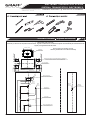
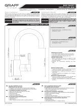
SHOWERHEAD INSTALLATION • LLUVIA DE DUCHA INSTALCIÓN

Colador
8
9
10
9
This faucet complies with NSF61/9, ASME/ANSI A112.18.1
and CSA B 125 Standards.
Este grifo se encuentra conforme con losestandares de NSF61/9,
de ASME/ANSI A112.18.1 y de CSA B 125.
Installation Instructions Instrucciones de Instalación
ELECTRONIC THERMOSTATIC SYSTEM
SISTEMA TERMOSTÁTICO ELECTRÓNICO
IOG 5032.00
Rev. 2 May 2018
4
NOTE! While designing the installation of the shower head, the installation method
enabling service access should be taken into account.
1. Corte un agujero en el techo falso, instale el mandril y marque los lugares del
techo para montar las anclas.
2. Haga 4 agujeros Ø11, apriete en ellos las anclas y golpee con martillo.
3. Atornille los 4 tornillos y bloquéelos con arandelas.
4. Cuando sea necesario corte los tornillos como en la figura.
5. Introduzca el mandril en el agujero del techo falso.
6. Ajuste la altura de montaje con arandelas.
7. Cuelgue los cordeles de montaje.
8. Conecte los cables de alimentación.
9 . Introduzca la lluvia de ducha en el mandril.
10. Atornille los 4 tornillos de fijación e introduzca las protecciones LED.
NOTA! Al diseñar la instalación del cabezal de ducha, debe tenerse en cuenta el
método de instalación que permita el acceso al servicio.
Anclas de montaje
USB cable
Cable USB
2-5/8"
66mm
5/16"
8mm
2-11/16"
68mm
q
1-13/16"
46mm
O
Mounting box
Caja de montaje
Screws
Tornillos
USB socket cover
Cubierta de enchufe USB
7
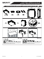
USB-PORT INSTALLATION
PUERTA-USB INSTALACIÓN
Drill four 11mm diameter holes

10
This faucet complies with NSF61/9, ASME/ANSI A112.18.1
and CSA B 125 Standards.
Este grifo se encuentra conforme con losestandares de NSF61/9,
de ASME/ANSI A112.18.1 y de CSA B 125.
Installation Instructions Instrucciones de Instalación
ELECTRONIC THERMOSTATIC SYSTEM
SISTEMA TERMOSTÁTICO ELECTRÓNICO
IOG 5032.00
Rev. 2 May 2018
1. Corte un agujero en el techo falso, instale el mandril y marque los lugares del
techo para montar las anclas.
2. Haga 4 agujeros Ø11, apriete en ellos las anclas y golpee con martillo.
3. Atornille los 4 tornillos y bloquéelos con arandelas.
4. Cuando sea necesario corte los tornillos como en la figura.
5. Introduzca el mandril en el agujero del techo falso.
6. Ajuste la altura de montaje con arandelas.
7. Cuelgue los cordeles de montaje.
8. Conecte los cables de alimentación.
9 . Introduzca la lluvia de ducha en el mandril.
10. Atornille los 4 tornillos de fijación e introduzca las protecciones LED.
NOTA! Al diseñar la instalación del cabezal de ducha, debe tenerse en cuenta el
método de instalación que permita el acceso al servicio.
Ø1-7/8”
Ø48mm
47-1/4”
1200mm
1
2
3
4
1.
2.
3.
4.
5.
Prepare the recess in the plumbing wall at an appropriate height – suggested height
of the USB port installation is 47–1/4” (1200 mm) – fig. 1.
While placing the mounting box in the installation recess, pull the USB cable through
the opening in the fixture. Fix the mounting box in the installation recess with bolts –
fig. 2.
Insert the USB cable to the USB port and fix it with 3 screws using the Allen wrench.
Put the USB port on the mounting box flange and fix it with a screw using the Allen
wrench.
Put the socket cover into the USB port – fig. 6
NOTE! While designing the installation of the USB port, the installation method
enabling service access should be taken into account.
8
SPEAKER INSTALLATION
ALTAVOZ INSTALACIÓN
4-13/16”
(122mm)
6-1/8”
(155mm)
6-1/8”
(155mm)
4-13/16”
(122mm)
5/16”
(8mm)
Speaker frame
Marco del altavoz
1
2
3
Tweeter
Tweeter

11
This faucet complies with NSF61/9, ASME/ANSI A112.18.1
and CSA B 125 Standards.
Este grifo se encuentra conforme con losestandares de NSF61/9,
de ASME/ANSI A112.18.1 y de CSA B 125.
Installation Instructions Instrucciones de Instalación
ELECTRONIC THERMOSTATIC SYSTEM
SISTEMA TERMOSTÁTICO ELECTRÓNICO
IOG 5032.00
Rev. 2 May 2018
4
5
6
NOTE! While designing the installation of the speakers, the installation method
enabling service access should be considered.
NOTA! Al diseñar la instalación de los altavoces, debe tenerse en cuenta el método
de instalación que permita el acceso al servicio.
CARE AND MAINTENANCE
CUIDADO Y MANTENIMIENTO
ENGLISH
~
ESPANOL
WARRANTY
GARANTÍA
Warranty conditions and warranty registration card are outlined on a
separate sheet.
Las condiciones de la garantía y la tarjeta del registro de la garantía se
encuentran en una pagina separada.
ENGLISH
~
ESPANOL
Your Graff product is designed and engineered in accordance with the
highest quality and performance standards. Be sure not to damage the
finish during installation. Care should be given to the cleaning of this
product. Although its finish is extremely durable, it can be damaged by
harsh abrasives or polish. Never use abrasive cleaners, acids,
solvents, etc. to clean any Graff product. To clean, simply wipe
gently with a damp cloth and blot dry with a soft towel.
Regularly wipe the lower part of the rainshower head thorough-
ly (with your palm or a soft cloth), once every 1-2 months, in
order to remove any dirt from the nozzles. Failing to do so may
result in damage to the casing of the rain shower head.
Su
producto
de
la Graff esta
diseńado
y
dirigido
acuerdo
con
los
estándare
s
de funcionamiento y calidad más altos. Este seguro no dańar las
terminaciones del grifo durante la instalación. Cuide el producto
manteniendolo siempre limpio. Aunque su acabado es extremadamen-
te durable, puede ser dańado por los abrasivos o pulientes ásperos.
Nunca utilice limpiadores abrasivos, ácidos, solventes, el etc.
para limpiar cualquier producto de la Graff. Para limpiar,
simplemente use un pańo húmedo y seque con una toalla suave.
Periódicamente (1-2 veces al mes), limpie la parte inferior del
rociador de ducha (con la mano o con
un paño suave) para
eliminar la suciedad acumulada en las boquillas. La falta de
limpieza periódica puede provocar el deterioro de su suerficie.
All dimensions and drawings are for reference only. For details, please refer to actual products.
Todas las dimensiones y dibujos sirven únicamente de referencia. Para consultar detalles, ver los productos.
-
 1
1
-
 2
2
-
 3
3
-
 4
4
-
 5
5
-
 6
6
-
 7
7
-
 8
8
-
 9
9
-
 10
10
-
 11
11


Graff Aqua-Sense Installation Instructions Manual
- Categoría
- Artículos sanitarios
- Tipo
- Installation Instructions Manual
en otros idiomas
- English: Graff Aqua-Sense
Artículos relacionados
-
 Graff G-9972 Guía de instalación
-
 Graff G-8052S Installation Instructions Manual
-
 Graff G-8053S Guía de instalación
-
 Graff G-5230-LM3 Guía de instalación
-
 Graff G-8714-PC Guía de instalación
-
 Graff G-4625-LM41K Guía de instalación
-
 Graff G-6135-LM41W-PC Guía de instalación
-
 Graff Oscar GN-4853 Guía de instalación
-
 Graff G-8504-PC Guía de instalación
-
 Graff Faucets G-6300-LM42-PC Guía de instalación