Metz MECABLITZ 44 AF-4 El manual del propietario
- Categoría
- Flashes de la cámara
- Tipo
- El manual del propietario
Este manual también es adecuado para

MECABLITZ 44 AF-4 C
Bedienungsanleitung Mode d’emploi
Gebruiksaanwijzing Operating instruction
Manuale istruzioni Manual de instrucciones
702 47 0091-A4 44 AF-4 C 16.08.2007 15:46 Uhr Seite 1

1. Sicherheitshinweise . . . . . . . . . . . . . . . . . . . . . . . . . . . . . . . . . . .3
2. Blitzgerät vorbereiten . . . . . . . . . . . . . . . . . . . . . . . . . . . . . . . . .4
2.1 Montage des Blitzgerätes . . . . . . . . . . . . . . . . . . . . . . . . . . . . . . .4
2.1.1Blitzgerät auf der Kamera montieren . . . . . . . . . . . . . . . . . . . . . . .4
2.1.2Blitzgerät von der Kamera abnehmen . . . . . . . . . . . . . . . . . . . . . .4
2.2 Stromversorgung . . . . . . . . . . . . . . . . . . . . . . . . . . . . . . . . . . . . .4
2.2.1Batterien- bzw. Akkuauswahl . . . . . . . . . . . . . . . . . . . . . . . . . . . .4
2.2.2Batterien austauschen . . . . . . . . . . . . . . . . . . . . . . . . . . . . . . . . .5
2.3 Ein- und Ausschalten des Blitzgerätes . . . . . . . . . . . . . . . . . . . . . .5
2.4 Automatische Geräteabschaltung / Auto - OFF . . . . . . . . . . . . . . .5
3. Programmblitzautomatik . . . . . . . . . . . . . . . . . . . . . . . . . . . . . . .6
4. Betriebsarten des Blitzgerätes . . . . . . . . . . . . . . . . . . . . . . . . . . .6
4.1 TTL-Blitzbetrieb . . . . . . . . . . . . . . . . . . . . . . . . . . . . . . . . . . . . . .6
4.1.1E-TTL-Blitzbetrieb . . . . . . . . . . . . . . . . . . . . . . . . . . . . . . . . . . . . .7
4.1.2Automatisches Aufhellblitzen bei Tageslicht mit TTL / E-TTL . . . . . . .7
4.2 Manuelle TTL-Blitzbelichtungskorrektur . . . . . . . . . . . . . . . . . . . . . .7
4.3 Belichtungskontrollanzeige . . . . . . . . . . . . . . . . . . . . . . . . . . . . . .8
4.4 Manueller Blitzbetrieb . . . . . . . . . . . . . . . . . . . . . . . . . . . . . . . . . .9
4.4.1Manueller Blitzbetrieb M mit voller Lichtleistung . . . . . . . . . . . . . . .9
4.4.2Manueller Blitzbetrieb MLo mit Teillichtleistung . . . . . . . . . . . . . . . .9
4.5 Blitztechniken . . . . . . . . . . . . . . . . . . . . . . . . . . . . . . . . . . . . . . . .9
4.5.1Indirektes Blitzen . . . . . . . . . . . . . . . . . . . . . . . . . . . . . . . . . . . . .9
4.5.2Nahaufnahmen / Makroaufnahmen . . . . . . . . . . . . . . . . . . . . . .10
4.6 Blitzsynchronisation . . . . . . . . . . . . . . . . . . . . . . . . . . . . . . . . . .10
4.6.1Normalsynchronisation . . . . . . . . . . . . . . . . . . . . . . . . . . . . . . . .10
4.6.2Synchronisation auf den 2.Verschlussvorhang (REAR-Betrieb) . . . .10
4.6.3Langzeitsynchronisation / SLOW . . . . . . . . . . . . . . . . . . . . . . . .11
4.6.4FP-Kurzzeitsynchronisation . . . . . . . . . . . . . . . . . . . . . . . . . . . . .11
4.7 Blitzbelichtungsspeicherung FE . . . . . . . . . . . . . . . . . . . . . . . . . .12
5. Blitzgerät- und Kamerafunktionen . . . . . . . . . . . . . . . . . . . . . . .12
5.1 Blitzbereitschaftsanzeige . . . . . . . . . . . . . . . . . . . . . . . . . . . . . . .12
5.2 Automatische Blitzsynchronzeitsteuerung . . . . . . . . . . . . . . . . . . .13
5.3 Anzeigen im Kamerasucher . . . . . . . . . . . . . . . . . . . . . . . . . . . .13
5.4 Anzeigen im LC-Display . . . . . . . . . . . . . . . . . . . . . . . . . . . . . . .13
5.4.1Reichweitenanzeige im TTL-Blitzbetrieb . . . . . . . . . . . . . . . . . . . .13
5.4.2Reichweitenanzeige im manuellen Blitzbetrieb M bzw. MLo . . . . . .14
5.4.3Überschreitung des Anzeigebereichs . . . . . . . . . . . . . . . . . . . . . .14
5.4.4Ausblendung der Reichweitenanzeige . . . . . . . . . . . . . . . . . . . . .14
5.4.5Meter - Feet - Umschaltung (m - ft) . . . . . . . . . . . . . . . . . . . . . . . .14
5.5 LC-Display-Beleuchtung . . . . . . . . . . . . . . . . . . . . . . . . . . . . . . .14
5.6 Motor-Zoom-Reflektor . . . . . . . . . . . . . . . . . . . . . . . . . . . . . . . .14
5.6.1„Auto-Zoom“ . . . . . . . . . . . . . . . . . . . . . . . . . . . . . . . . . . . . . . .14
5.6.2Manueller Zoom-Betrieb „M. Zoom“ . . . . . . . . . . . . . . . . . . . . . .14
5.6.3Extended-Zoom-Betrieb . . . . . . . . . . . . . . . . . . . . . . . . . . . . . . .15
5.7 Autofokus-Messblitz . . . . . . . . . . . . . . . . . . . . . . . . . . . . . . . . . .16
5.8 Zurück zur Grundeinstellung . . . . . . . . . . . . . . . . . . . . . . . . . . . .16
6. Spezielle Kamerahinweise . . . . . . . . . . . . . . . . . . . . . . . . . . . . .17
6.1 Im Blitzbetrieb nicht unterstützte Sonderfunktionen . . . . . . . . . . . .17
6.1.1Schärfenautomatik . . . . . . . . . . . . . . . . . . . . . . . . . . . . . . . . . . .17
6.1.2Weichzeichner (SF) . . . . . . . . . . . . . . . . . . . . . . . . . . . . . . . . . .17
6.1.3Programmverschiebung / Programm-Shift . . . . . . . . . . . . . . . . . .17
7. Sonderzubehör . . . . . . . . . . . . . . . . . . . . . . . . . . . . . . . . . . . . .17
8. Hilfe bei Störungen . . . . . . . . . . . . . . . . . . . . . . . . . . . . . . . . . .17
9. Wartung und Pflege . . . . . . . . . . . . . . . . . . . . . . . . . . . . . . . . .17
10. Technische Daten . . . . . . . . . . . . . . . . . . . . . . . . . . . . . . . . . . . .18
Garantiebestimmungen . . . . . . . . . . . . . . . . . . . . . . . . . . . . . . . . . . . .20
Leitzahlentabelle für TTL und volle Lichtleistung M im Meter-System . . . .112
Ķ
2
702 47 0091-A4 44 AF-4 C 16.08.2007 15:46 Uhr Seite 2

Vorwort
Vielen Dank, dass Sie sich für ein Metz Produkt entschieden haben. Wir freu-
en uns, Sie als Kunde begrüßen zu dürfen.
Natürlich können Sie es kaum erwarten, das Blitzgerät in Betrieb zu nehmen.
Es lohnt sich aber, die Bedienungsanleitung zu lesen, denn nur so lernen Sie,
mit dem Gerät problemlos umzugehen.
Das Blitzgerät mecablitz 44 AF–4C ist für analoge und digitale Canon
AF–Kameras mit TTL-Blitzsteuerung bzw. E-TTL-Blitzsteuerung geeignet.
Für Kameras anderer Hersteller ist das Blitzgerät nicht geeignet!
1. Sicherheitshinweise
• Das Blitzgerät ist ausschließlich zur Verwendung im fotografischen Be-
reich vorgesehen und zugelassen !
• In Umgebung von entflammbaren Gasen oder Flüssigkeiten (Benzin,
Lösungsmittel etc.) darf das Blitzgerät keinesfalls ausgelöst werden !
EXPLOSIONSGEFAHR !
• Auto-, Bus-, Fahrrad-, Motorrad-, oder Zugfahrer etc. niemals während
der Fahrt mit einem Blitzgerät fotografieren. Durch die Blendung kann
der Fahrer einen Unfall verursachen !
• Lösen Sie in unmittelbarer Nähe der Augen keinesfalls einen Blitz aus!
Ein Blitzlicht direkt vor den Augen von Personen und Tieren kann zur
Netzhautschädigung führen und schwere Sehstörungen verursachen - bis
hin zur Blindheit !
• Nur die in der Bedienungsanleitung bezeichneten und zugelassenen
Stromquellen verwenden !
• Batterien/Akkus nicht übermäßiger Wärme wie Sonnenschein, Feuer
oder dergleichen aussetzen !
• Verbrauchte Batterien/Akkus nicht ins Feuer werfen !
• Aus verbrauchten Batterien kann Lauge austreten, was zur Beschädigung
der Kontakte führt. Verbrauchte Batterien deshalb immer aus dem Gerät
entnehmen.
• Trockenbatterien dürfen nicht geladen werden.
• Blitz- und Ladegerät nicht Tropf- und Spritzwasser (z.B. Regen) aus-
setzen !
• Schützen Sie Ihr Blitzgerät vor großer Hitze und hoher Luftfeuchtigkeit !
Blitzgerät nicht im Handschuhfach des Autos aufbewahren !
• Beim Auslösen eines Blitzes darf sich kein lichtundurchlässiges Material
unmittelbar vor oder direkt auf der Reflektorscheibe befinden. Die
Reflektorscheibe darf nicht verunreinigt sein. Bei Nichtbeachtung kann
es, durch die hohe Energie des Blitzlichtes, zu Verbrennungen des
Materials bzw. der Reflektorscheibe führen.
• Nach mehrfachem Blitzen nicht die Reflektorscheibe berühren.
Verbrennungsgefahr !
• Blitzgerät nicht zerlegen ! HOCHSPANNUNG ! Im Geräteinneren befin-
den sich keine Bauteile, die von einem Laien repariert werden können.
• Bei Serienblitzaufnahmen mit voller Lichtleistung und den kurzen Blitz-
folgezeiten des NC-Akku-Betriebes ist darauf zu achten, dass nach je-
weils 15 Blitzen eine Pause von mindestens 10 Minuten eingehalten
wird. Somit vermeiden Sie eine Überlastung des Gerätes.
• Das Blitzgerät darf nur dann zusammen mit einem in die Kamera einge-
bauten Blitzgerät verwendet werden, wenn dieses vollständig ausge-
klappt werden kann!
• Bei raschem Temperaturwechsel kann Feuchtigkeitsbeschlag auftreten.
Gerät akklimatisieren lassen!
• Keine schadhaften Batterien oder Akkus verwenden !
3
Ķ
Schlagen Sie bitte auch die Bildseite des Umschlages am
Ende der Anleitung auf.
☞
702 47 0091-A4 44 AF-4 C 16.08.2007 15:46 Uhr Seite 3

Ķ
4
Dedicated-Blitzfunktionen
Die Dedicated Blitzfunktionen sind speziell auf das Kamerasystem ab-
gestimmte Blitzfunktionen. In Abhängigkeit vom Kameratyp werden
dabei verschiedene Blitzfunktionen unterstützt. Im Rahmen dieser
Bedienungsanleitung ist es nicht möglich alle Kameratypen mit den
einzelnen Dedicated Blitzfunktionen detailliert zu beschreiben.
Beachten Sie deshalb die Hinweise zum Blitzbetrieb in der Bedie-
nungsanleitung Ihrer Kamera, da verschiedene Dedicated-
Blitzfunktionen von Ihrem Kameratyp eventuell nicht unterstützt wer-
den bzw. an der Kamera selbst eingestellt werden müssen!
• Blitzbereitschaftsanzeige im Kamerasucher / Monitor / Display
• Automatische Blitzsynchronzeitsteuerung
• TTL-Blitzsteuerung
2)
;
• E-TTL-Blitzbetrieb
2)
;
• Automatisches Aufhellblitzen bei Tageslicht mit TTL / E-TTL
• Manuelle Blitzbelichtungskorrektur bei TTL / E-TTL
2)
;
• Blitzbelichtungsspeicherung FE bei E-TTL
1)
;
• Synchronisation auf den 1. oder 2. Verschlussvorhang (REAR)
2)
;
• FP-Kurzzeitsynchronisation (HSS-Blitzbetrieb)
2)
;
• Motor-Zoom-Steuerung
• AF-Messblitzsteuerung
• Blitzreichweitenanzeige
• Programmblitzautomatik / Automatik-Blitz (AUTO-FLASH)
1)
• Wake-Up-Funktion
Beachten Sie:
Ohne Zusatz: Automatische Aktivierung der Funktion.
1)
= Einstellung muss an der Kamera erfolgen.
2)
= Einstellung muss am Blitzgerät erfolgen.
☞
2. Blitzgerät vorbereiten
2.1 Montage des Blitzgerätes
2.1.1 Blitzgerät auf der Kamera montieren
Kamera und Blitzgerät vor der Montage oder Demontage ausschalten.
• Rändelmutter (Bild 3) bis zum Anschlag gegen das Blitzgerät drehen. Der
Sicherungsstift im Schuh ist jetzt vollkommen im Gehäuse des Blitzgerätes
versenkt.
• Blitzgerät mit dem Anschlussfuß bis zum Anschlag in den Zubehörschuh
der Kamera schieben.
•
Rändelmutter
(Bild 3)
bis zum Anschlag gegen das Kameragehäuse drehen
und das Blitzgerät festklemmen. Bei Kameragehäusen, die kein
Sicherungsloch aufweisen, versenkt sich der federgelagerte Sicherungsstift im
Gehäuse des Blitzgerätes, damit die Oberfläche nicht beschädigt wird.
2.1.2 Blitzgerät von der Kamera abnehmen
Kamera und Blitzgerät vor der Montage oder Demontage ausschalten.
• Rändelmutter (Bild 3) bis zum Anschlag gegen das Blitzgerät drehen.
• Blitzgerät aus dem Zubehörschuh der Kamera herausziehen.
2.2 Stromversorgung
2.2.1 Batterien- bzw. Akkuauswahl
Das Blitzgerät kann wahlweise betrieben werden mit:
•
4 NC-Akkus 1,2 V Typ IEC KR6 (AA / Mignon) , sie bieten sehr kurze
Blitzfolgezeiten und sparsamen Betrieb, da sie wiederaufladbar sind.
•
4 Nickel-Metall-Hydrid Akkus
1,2 V
Typ
IEC
HR6 (AA / Mignon), deutlich
höhere Kapazität als NC-Akku und weniger umweltschädlich da cadmium
frei.
• 4 Alkali-Mangan-Trockenbatterien
1,5 V
Typ IEC LR6 (AA / Mignon), war-
tungsfreie Stromquelle für gemäßigte Leistungsanforderungen.
• 4 Lithium-Batterien
1,5 V
Typ IEC FR6 (AA / Mignon), wartungsfreie
Stromquelle mit hoher Kapazität und geringer Selbstentladung.
☞
☞
702 47 0091-A4 44 AF-4 C 16.08.2007 15:46 Uhr Seite 4

Wenn Sie das Blitzgerät längere Zeit nicht benutzen, entfernen Sie
bitte die Batterien aus dem Gerät.
2.2.2 Batterien austauschen (Bild 4)
Die Batterien sind leer bzw. verbraucht, wenn die Blitzfolgezeit (Zeit vom
Auslösen eines Blitzes mit voller Lichtleistung, z.B. bei M, bis zum erneuten
Aufleuchten der Blitzbereitschaftsanzeige) über 60 Sekunden ansteigt.
• Blitzgerät mit dem Hauptschalter (Bild 2) ausschalten.
• Den Batteriefachdeckel nach vorne schieben und aufklappen.
• Batterien bzw. Akkus in Längsrichtung entsprechend den angegebenen
Batteriesymbolen einsetzen und Batteriedeckel schließen.
Achten Sie beim Einsetzen der Batterien bzw. Akkus auf die richtige
Polarität gemäß den Symbolen im Batteriefach. Vertauschte Pole kön-
nen zur Zerstörung des Gerätes führen! Explosionsgefahr bei unsach-
gemäßem Auswechseln der Batterien.
Ersetzen Sie immer alle Batterien durch gleiche, hochwertige Batterien
eines Herstellertyps mit gleicher Kapazität! Verbrauchte Batterien
bzw. Akkus gehören nicht in den Hausmüll! Leisten Sie einen Beitrag
zum Umweltschutz und geben Sie verbrauchte Batterien bzw. Akkus
bei entsprechenden Sammelstellen ab!
2.3 Ein- und Ausschalten des Blitzgerätes
Das Blitzgerät wird mit dem Hauptschalter (Bild 2) auf dem
Batteriefachdeckel eingeschaltet. In der oberen Stellung „ON“ ist das
Blitzgerät eingeschaltet.
Zum Ausschalten den Hauptschalter in die untere Position schieben.
Wird das Blitzgerät längere Zeit nicht gebraucht, so empfehlen wir:
Blitzgerät mit dem Hauptschalter ausschalten und die Stromquellen
(Batterien, Akkus) entnehmen.
2.4 Automatische Geräteabschaltung / Auto - OFF (Bild 5)
Werksseitig ist das Blitzgerät so eingestellt, dass es ca. 3 Minuten -
• nach dem Einschalten,
☞
☞
☞
• nach dem Auslösen eines Blitzes,
• nach dem Antippen des Kameraauslösers,
• nach dem Ausschalten des Kamerabelichtungsmesssystems...
...in den Standby-Betrieb schaltet (Auto-OFF), um Energie zu sparen und die
Stromquellen vor unbeabsichtigtem Entladen zu schützen. Die Blitzbereit-
schaftsanzeige und die Anzeigen auf dem LC-Display verlöschen.
Die zuletzt benutzte Betriebseinstellung bleibt nach der automatischen Ab-
schaltung erhalten und steht nach dem Einschalten sofort wieder zur Ver-
fügung. Das Blitzgerät wird durch Drücken der Tasten „Mode“ oder „Zoom“
bzw. durch Antippen des Kameraauslösers (Wake-Up-Funktion) wieder ein-
geschaltet.
Wenn das Blitzgerät längere Zeit nicht benötigt wird, sollte das Gerät
grundsätzlich immer mit dem Hauptschalter ausgeschaltet werden!
Bei Bedarf kann die automatische Geräteabschaltung deaktiviert werden:
Ausschalten der automatischen Geräteabschaltung
• Blitzgerät mit dem Hauptschalter einschalten.
• Tastenkombination „Select“ (= Taste „Mode“ + Taste „Zoom“) so oft
drücken, bis im LC-Display „3m“ (für 3 Minuten) angezeigt wird.
• Taste „Zoom“ so oft drücken, bis im LC-Display „OFF“ blinkt.
• Die Einstellung wird sofort wirksam. Nach ca. 5s schaltet das LC-Display
auf die normale Anzeige zurück.
Einschalten der automatischen Geräteabschaltung
• Blitzgerät mit dem Hauptschalter einschalten.
• Tastenkombination „Select“ (= Taste „Mode“ + Taste „Zoom“) so oft drü-
cken, bis im LC-Display „3m“ (für 3 Minuten) angezeigt wird.
• Taste „Zoom“ so oft drücken, bis im LC-Display des „On“ blinkt.
• Die Einstellung wird sofort wirksam. Nach ca. 5s schaltet das LC-Display
auf die normale Anzeige zurück.
☞
5
Ķ
702 47 0091-A4 44 AF-4 C 16.08.2007 15:46 Uhr Seite 5

3. Programmblitzautomatik (Blitz-Vollautomatik)
In der Programmblitzautomatik steuert die Kamera die Blende, Verschlusszeit
und das Blitzgerät automatisch so, dass in den meisten Aufnahmesituatio-
nen, auch im Aufhellblitzbetrieb, zusammen mit dem Blitzlicht ein optimales
Aufnahmeergebnis erzielt wird.
Einstellung an der Kamera
Stellen Sie Ihre Kamera in die Betriebsart „grünes Vollprogramm“, Programm
„P“ oder ein Motiv-Kreativ-Programm (Landschaft, Porträt, Sport usw.). Am
Objektiv die Autofokus-Betriebsart „AF“ wählen. Einstellvorgang siehe Kame-
rabedienungsanleitung.
Verwenden Sie beim „Nachtaufnahme-Programm“ ein Stativ, um die
Gefahr von verwackelten Aufnahmen bei langen Verschlusszeiten zu
vermeiden!
Einstellung am Blitzgerät
Stellen Sie das Blitzgerät in die Betriebsart „TTL“ bzw. “E-TTL” (siehe 4.1).
Bei verschiedenen Kameras wird im grünen Vollprogramm und in
den Motiv-Kreativ-Programmen automatisch in den TTL-Blitzbetrieb
bzw. E-TTL-Blitzbetrieb des Blitzgerätes geschaltet!
Sowie Sie obige Einstellungen vorgenommen haben, können Sie problemlos
mit Ihren Blitzlichtaufnahmen beginnen, wenn das Blitzgerät seine Blitzbe-
reitschaft anzeigt (siehe 5.1)!
Automatik-Blitz (AUTO-Flash)
Bei verschiedenen Kameras kann in bestimmen Betriebsarten die automati-
sche Zuschaltung des Blitzgerätes (AUTO-Flash) aktiviert werden. Dabei wird
vom Blitzgerät nur dann ein Blitz ausgelöst, wenn das Messsystem der Ka-
mera dies für erforderlich hält. Nähere Hinweise entnehmen Sie der Kamera-
bedienungsanleitung.
☞
☞
4. Betriebsarten des Blitzgerätes
4.1 TTL-Blitzbetrieb (Bild 6)
Im TTL-Blitzbetrieb erreichen Sie auf einfache Art sehr gute Blitzlichtauf-
nahmen. In dieser Blitzbetriebsart wird die Belichtungsmessung von einem
Sensor in der Kamera vorgenommen. Dieser misst das durchs Objektiv (TTL =
„T
rough The Lens“) auf den Film auftreffende Licht. Beim Erreichen der erfor-
derlichen Lichtmenge sendet die Kameraelektronik ein Stopp-Signal an das
Blitzgerät und die Lichtabstrahlung wird sofort unterbrochen. Der Vorteil die-
ses Blitzbetriebes liegt darin, dass alle Faktoren, welche die Belichtung des
Films beeinflussen (Aufnahmefilter, Blenden- und Brennweitenänderungen bei
Zoom-Objektiven, Auszugsverlängerungen für Nahaufnahmen usw.), automa-
tisch bei der Regelung des Blitzlichtes berücksichtigt werden. Sie brauchen
sich nicht um die Blitzeinstellung zu kümmern, die Kameraelektronik sorgt
automatisch für die richtige Blitzlichtdosierung. Für die Reichweite des Blitz-
lichtes beachten Sie die entsprechende Anzeige im LC–Display des Blitz-
gerätes (siehe 5.4). Bei einer korrekt belichteten Blitzlichtaufnahme erscheint
für ca. 3s am LC-Display des Blitzgerätes die „o.k.“-Anzeige (siehe 4.3).
Der TTL-Blitzbetrieb wird von den analogen Canon-AF-Kameras in allen
Kamerabetriebsarten (z.B. „grünes Vollprogramm“, Programm „P“, Zeit-
automatik „Av“, Blendenautomatik „Tv“, Motiv- Kreativ-Programme, Manuell
„M“ usw.) unterstützt. Die meisten Canon-Digitalkameras unterstützen den
normalen TTL-Blitzbetrieb nicht. Bei diesen Kameras muss
der E-TTL-Blitz-
betrieb (siehe 4.1.1) gewählt werden!
Zum Testen der TTL-Funktion muss sich ein Film in der Kamera befin-
den! Beachten Sie bei der Filmauswahl, ob es für Ihre Kamera Ein-
schränkungen hinsichtlich der maximalen Filmempfindlichkeit bzw.
ISO-Zahl (z.B. maximal ISO 1000) für den TTL-Blitzbetrieb gibt (siehe
Kamerabedienungsanleitung)!
Einstellvorgang für den TTL-Blitzbetrieb
Bei verschiedenen Kameras wird der TTL–Blitzbetrieb im „grünen Voll-
programm“ bzw. den Motiv- Kreativ-Programmen automatisch am
Blitzgerät aktiviert.
☞
☞
6
Ķ
702 47 0091-A4 44 AF-4 C 16.08.2007 15:46 Uhr Seite 6

• Blitzgerät mit dem Hauptschalter einschalten.
• Taste „Mode“ so oft drücken, bis im LC-Display „TTL“ blinkt.
• Die Einstellung wird sofort wirksam. Nach ca. 5s schaltet das LC-Display
auf die normale Anzeige zurück.
Bei starken Kontrastunterschieden, z.B. dunkles Objekt im Schnee, kann eine
Belichtungskorrektur erforderlich sein (siehe Kapitel 4.2).
4.1.1 E-TTL-Blitzbetrieb
Der E-TTL-Blitzbetrieb ist eine weiterentwickelte Variante des “normalen”
TTL–Blitzbetriebes. Er wird von den digitalen und verschiedenen analogen
Canon-Kameras unterstützt. Beim E-TTL-Blitzbetrieb werden unmittelbar vor
der eigentlichen Aufnahme die Reflexionseigenschaften des Motivs durch
einen Messvorblitz ermittelt. Aufgrund einer gewichteten Mehrfeldmessung
vom Lichtsensor in der Kamera wird an das Blitzgerät eine Blitz-Teillichtleis-
tung übertragen und dort eingestellt. Mit dieser Blitz-Teillichtleistung wird
dann das Motiv vom Blitzgerät mit dem anschließenden Hauptblitz belichtet.
Der Messvorblitz selbst trägt nicht zur Belichtung des Motivs bei.
Damit der E-TTL-Blitzbetrieb am Blitzgerät aktiviert werden kann,
muss ein vollständiger Datenaustausch zwischen Blitzgerät und Ka-
mera stattgefunden haben. Dazu ist es erforderlich, dass nach dem
Einschalten von Blitzgerät und Kamera der Kameraauslöser einige
Sekunden lang angetippt wird.
Die meisten Digitalkameras unterstützen in den Kamerabetriebsarten
“Vollprogramm” (bzw. “AUTO”), Programm “P”, “Av”, “Tv” und den
Motiv-Kreativ-Programmen nur den E-TTL-Blitzbetrieb. Andere Blitzbe-
triebsarten, z.B. normales TTL oder Manuell M bzw. MLo sind in die-
sen Kamerabetriebsarten nicht möglich! Die Blitzbetriebsart Manuell
M bzw. MLo wird von den Digitalkameras nur in der manuellen
Kamerabetriebsart “M” unterstützt. Beachten Sie hierzu die Hinweise
in der Kamerabedienungsanleitung.
Systembedingt können im E-TTL-Blitzbetrieb mit Digitalkameras keine
Reflektorvorsatzscheiben (Streuscheiben, Bouncer, Farbfilter usw.) ver-
wendet werden, da es sonst zu Fehlbelichtungen kommt.
☞
☞
☞
Einstellvorgang für den E-TTL-Blitzbetrieb
Bei verschiedenen Kameras wird der E-TTL-Blitzbetrieb im “grünen
Vollprogramm” bzw. den Motiv-Kreativ-Programmen automatisch am
Blitzgerät aktiviert.
• Blitzgerät mit dem Hauptschalter einschalten.
• Taste “Mode” so oft drücken, bis im LC-Display “E-TTL” blinkt.
• Die Einstellung wird sofort wirksam. Nach ca. 5s schaltet das LC-Display
auf die normale Anzeige zurück.
Bei starken Kontrastunterschieden, z.B. dunkles Objekt im Schnee, kann eine
Belichtungskorrektur erforderlich sein (siehe Kapitel 4.2).
4.1.2 Automatisches Aufhellblitzen bei Tageslicht mit TTL / E-TTL
(Bild 8 und 9)
Bei den meisten Kameratypen wird im grünen Vollprogramm, Programmauto-
matik P und den Motiv-Kreativ-Programmen bei Tageslicht automatisch der
Aufhellblitzbetrieb aktiviert (siehe Kamerabedienungsanleitung).
Mit dem Aufhellblitz können Sie lästige Schatten beseitigen und bei Gegen-
lichtaufnahmen eine ausgewogene Belichtung zwischen Motiv und Bildhin-
tergrund erreichen. Ein computergesteuertes Messsystem der Kamera sorgt für
die geeignete Kombination von Verschlusszeit, Arbeitsblende und Blitzleistung.
Das Blitzgerät wird dazu in der Betriebsart TTL bzw. E-TTL betrieben.
Achten Sie darauf, dass die Gegenlichtquelle nicht direkt ins Objektiv
scheint. Das TTL-Messsystem der Kamera würde dadurch getäuscht!
Eine Einstellung oder Anzeige für den automatischen TTL-Aufhellblitzbetrieb
am Blitzgerät erfolgt in diesem Fall nicht.
4.2 Manuelle TTL-Blitzbelichtungskorrektur bei TTL / E-TTL
Die TTL-Blitzbelichtungsautomatik der meisten Kameras ist auf einen Refle-
xionsgrad des Motivs von 25% (durchschnittlicher Reflexionsgrad von Blitz-
motiven) abgestimmt. Ein dunkler Hintergrund, der viel Licht absorbiert, oder
ein heller Hintergrund, der stark reflektiert, können zu Über- bzw. Unterbe-
lichtung des Motivs führen.
☞
☞
7
Ķ
702 47 0091-A4 44 AF-4 C 16.08.2007 15:46 Uhr Seite 7

Um den oben genannten Effekt zu kompensieren, kann bei einigen Kameras die
TTL-Blitzbelichtung bzw. E-TTL-Blitzbelichtung manuell mit einem Korrekturwert
der Aufnahmesituation angepasst werden. Die Höhe des Korrekturwertes ist
vom Kontrast zwischen Motiv und Bildhintergrund abhängig!
Dunkles Motiv vor hellem Bildhintergrund: Positiver Korrekturwert. Helles Motiv
vor dunklem Bildhintergrund: Negativer Korrekturwert . Beim Einstellen eines
Korrekturwertes kann sich die Reichweitenanzeige im LC-Display ändern und
dem Korrekturwert angepasst werden (abhängig von Kameratyp)!
Eine Belichtungskorrektur durch Verändern der Objektivblende ist nicht mög-
lich, da die Belichtungsautomatik der Kamera die geänderte Blende wie-
derum als normale Arbeitsblende betrachtet.
Vergessen Sie nicht, die TTL-Blitzbelichtungskorrektur nach der
Aufnahme an der Kamera wieder zurückzustellen!
Korrekturwerteinstellung
• Blitzgerät auf die Kamera montieren.
• Blitzgerät und Kamera einschalten.
• Kameraauslöser antippen, damit ein Datenaustausch zwischen Blitzgerät
und Kamera stattfinden kann.
• Tastenkombination “Select” (= Taste “Mode” + Taste “Zoom”) so oft drü-
cken, bis im LC-Display EV (Exposure Value = Blendenwert) angezeigt
wird. Neben EV wird der eingestellte Korrekturwert blinkend angezeigt.
• Während die Anzeige für den Korrekturwert blinkt, kann mit der Taste
“Zoom” ein positiver bzw. mit der Taste “Mode” ein negativer Korrektur-
wert eingestellt werden.
Der Einstellbereich für den Korrekturwert erstreckt sich von -3 bis +3 Blenden-
werten in Drittel Blendenstufen.
Die Einstellung wird sofort wirksam. Nach ca. 5s schaltet das LC-Display auf
die normale Anzeige zurück.
Wenn ein Korrekturwert eingestellt wurde, blinkt zum Hinweis am LC-Display
des Blitzgerätes EV neben dem Blendensymbol.
☞
Verschiedene Kameras bieten die Möglichkeit zur Einstellung eines
manuellen Korrekturwertes an der Kamera selbst. Wir empfehlen, bei
diesen Kameras die Einstellung des Korrekturwertes entweder
an der
Kamera oder
am Blitzgerät vorzunehmen.
Löschen der manuellen TTL-Blitzbelichtungskorrektur am Blitzgerät
• Tastenkombination “Select” (= Taste “Mode” + Taste “Zoom”) so oft drü-
cken, bis im LC-Display EV angezeigt wird.
• Neben EV wird der eingestellte Korrekturwert blinkend angezeigt.
• Während die Anzeige für den Korrekturwert blinkt, wird mit der Taste
“Zoom” bzw. mit der Taste “Mode” der Korrekturwert auf 0.0 eingestellt
und damit gelöscht.
Die Einstellung wird sofort wirksam. Nach ca. 5s schaltet das LC-Display auf
die normale Anzeige zurück.
Korrekturwerteinstellung an der Kamera
Bei verschiedenen Kameras (z.B. PowerShot G1, G2, G3 und
Pro 90IS) muss ein manueller Korrekturwert für die Blitzbelichtung
grundsätzlich an der Kamera eingestellt werden. Die Einstellung am
Blitzgerät ist nicht möglich bzw. unwirksam! Beachten Sie die entspre-
chenden Hinweise in der Kamerabedienungsanleitung!
4.3 Belichtungskontrollanzeige „o.k.“ (Bild 7)
Die Belichtungskontrollanzeige „o.k.“ erscheint im LC-Display des Blitzgerätes
nur, wenn die Aufnahme im TTL-Blitzbetrieb bzw. E-TTL-Blitzbetrieb richtig
belichtet wurde! Im manuellen Betrieb M bzw. MLo erfolgt keine Belichtungs-
kontrollanzeige.
Erfolgt im TTL- bzw. E-TTL-Blitzbetrieb keine Belichtungskontrollanzeige „o.k.“
nach der Aufnahme, so wurde die Aufnahme unterbelichtet und Sie müssen
die nächst kleinere Blendenzahl einstellen (z.B. anstatt Blende 11 die Blende
8) oder die Entfernung zum Motiv bzw. zur Reflexfläche (z.B. beim indirekten
Blitzen) verkleinern und die Aufnahme wiederholen. Beachten Sie die Reich-
weitenanzeige im LC-Display des Blitzgerätes (siehe 5.4.1).
Im Kamerasucher erfolgt keine Belichtungskontrollanzeige!
☞
☞
☞
8
Ķ
702 47 0091-A4 44 AF-4 C 16.08.2007 15:46 Uhr Seite 8

4.4 Manueller Blitzbetrieb
Mit verschiedenen Kameras wird im „grünen Vollprogramm“ und den
Motiv-Kreativ-Programmen das Blitzgerät automatisch auf den
TTL-bzw. E-TTL-Blitzbetrieb umgeschaltet. Der manuelle Blitzbetrieb ist
dann nicht möglich! Im manuellen Blitzbetrieb erfolgt keine Belich-
tungskontrollanzeige auf dem LC-Display des Blitzgerätes!
Die Kamera ist in die Betriebsart Zeitautomatik „Av“ bzw. in die manuelle
Betriebsart „M“ oder „X“ zu schalten. Blende und Verschlusszeit (bei „M“)
sind an der Kamera entsprechend der Aufnahmesituation zu wählen (siehe
Kamerabedienungsanleitung).
4.4.1 Manueller Blitzbetrieb M mit voller Lichtleistung
In dieser Betriebsart wird vom Blitzgerät stets ein ungeregelter Blitz mit voller
Lichtleistung abgegeben. Die Anpassung an die Aufnahmesituation erfolgt
durch die Blendeneinstellung an der Kamera. Im LC-Display des Blitzgerätes
wird die Entfernung vom Blitzgerät zum Motiv angezeigt, die für eine korrek-
te Blitzbelichtung einzuhalten ist (siehe auch 5.4.2).
Einstellvorgang für den manuellen Blitzbetrieb M
• Blitzgerät mit dem Hauptschalter einschalten.
• Taste „Mode“ so oft drücken, bis im LC-Display „M“ blinkt.
• Die Einstellung wird sofort wirksam. Nach ca. 5s schaltet das LC-Display
auf die normale Anzeige zurück.
4.4.2 Manueller Blitzbetrieb MLo mit Teillichtleistung
In dieser Betriebsart wird vom Blitzgerät stets ein ungeregelter Blitz mit einer
manuellen Teillichtleistung (Low) abgegeben. Die Anpassung an die Aufnah-
mesituation erfolgt z.B. durch Auswahl einer geeigneten manuellen Teillicht-
leistung bzw. durch die Blendeneinstellung an der Kamera. Im LC-Display
des Blitzgerätes wird die Entfernung angezeigt, die für eine korrekte Blitz-
belichtung einzuhalten ist (siehe auch 5.4.2).
Einstellvorgang für den manuellen Blitzbetrieb MLo:
• Blitzgerät mit dem Hauptschalter einschalten.
☞
• Taste “Mode” so oft drücken, bis im LC-Display “MLo” blinkt.
• Die Einstellung wird sofort wirksam. Nach ca. 5s schaltet das LC-Display
auf die normale Anzeige zurück.
4.5 Blitztechniken
4.5.1 Indirektes Blitzen
Direkt geblitzte Bilder sind nicht selten an ihrer typisch harten und ausge-
prägten Schattenbildung zu erkennen. Oft wirkt auch der physikalisch be-
dingte Lichtabfall vom Vordergrund zum Hintergrund störend. Durch indirek-
tes Blitzen können diese Erscheinungen weitgehend vermieden werden, weil
das Objekt und der Hintergrund mit zerstreutem Licht weich und gleichmäßig
ausgeleuchtet werden können. Der Reflektor wird dabei so geschwenkt, dass
er geeignete Reflexflächen (z.B. Decke oder Wände des Raumes) beleuchtet.
Der Reflektor des Blitzgerätes ist bis zu 90° vertikal schwenkbar. Zum
Schwenken des Reflektorkopfes nach unten den Entriegelungsknopf drücken.
Beim vertikalen Schwenken des Reflektors ist darauf zu achten, dass um
einen genügend großen Winkel geschwenkt wird, damit kein direktes Licht
vom Reflektor auf das Motiv fallen kann. Deshalb mindestens bis zur 60°
Rastposition schwenken. Im LC-Display erlöschen die Entfernungsangaben.
Der Motivabstand, vom Blitzgerät über Decke oder Wand zum Motiv, ist jetzt
eine unbekannte Größe.
Das von den Reflexflächen zerstreut reflektierte Licht ergibt eine weiche
Ausleuchtung des Objektes. Die reflektierende Fläche muss farbneutral bzw.
weiß sein und sollte keine Strukturen aufweisen (z. B. Holzbalken an der
Decke), die zu Schattenbildung führen können. Für Farbeffekte wählt man
Reflexflächen in der entsprechenden Farbe.
Beachten Sie, dass die Reichweite des Blitzlichtes beim indirekten
Blitzen stark abnimmt. Für normale Zimmerhöhe kann man sich zur
Ermittlung der maximalen Reichweite mit folgender Faustformel behel-
fen:
Leitzahl
Reichweite = ———————————————
Beleuchtungsabstand x 2
☞
9
Ķ
702 47 0091-A4 44 AF-4 C 16.08.2007 15:46 Uhr Seite 9

4.5.2 Nahaufnahmen / Makroaufnahmen
Um Parallaxefehler auszugleichen, kann der Blitzreflektor um einem Winkel
von -7° nach unten geschwenkt werden. Dazu den Entriegelungsknopf des
Reflektors drücken und den Reflektor nach unten schwenken.
Bei Aufnahmen im Nahbereich ist zu beachten, dass bestimmte Mindestbe-
leuchtungsabstände eingehalten werden müssen, um eine Überbelichtung zu
vermeiden.
Der Mindestbeleuchtungsabstand beträgt ca. 10% der im LC-Display
angezeigten Reichweite. Da beim nach unten geschwenkten Reflektor
im LC-Display keine Reichweite angezeigt wird, sollten Sie sich an der
Reichweite orientieren, die das Blitzgerät anzeigt, wenn sich der Blitz-
reflektor in der Normalposition befindet.
4.6 Blitzsynchronisation
4.6.1 Normalsynchronisation (Bild 10)
Bei der Normalsynchronisation wird das Blitzgerät zum Beginn der Ver-
schlusszeit ausgelöst (Synchronisation auf den 1.Verschlussvorhang). Die
Normalsynchronisation ist der Standardbetrieb und wird von allen Kameras
ausgeführt. Sie ist für die meisten Blitzaufnahmen geeignet. Die Kamera wird
abhängig von ihrer Betriebsart, auf die Kamerasynchronzeit umgeschaltet.
Üblich sind Zeiten zwischen 1/30s und 1/125s (siehe Kamerabedienungs-
anleitung). Am Blitzgerät erfolgt keine Einstellung bzw. Anzeige für diesen
Betrieb.
4.6.2 Synchronisation auf den 2.Verschlussvorhang (REAR-Betrieb)
(Bild 11)
Einige Kameras bieten die Möglichkeit zur Synchronisation auf den 2. Ver-
schlussvorhang (REAR-Betrieb). Dabei wird das Blitzgerät erst zum Ende der
Verschlusszeit ausgelöst. Dies ist vor allem bei Belichtungen mit langen Ver-
schlusszeiten (länger als z.B. 1/30 Sekunde) und bewegten Motiven mit
eigener Lichtquelle von Vorteil, weil bewegte Lichtquellen dann einen Licht-
schweif hinter sich herziehen, anstatt ihn - wie beim Synchronisieren auf den
1. Verschlussvorhang - vor sich aufzubauen. Mit dem Synchronisieren auf
☞
den 2. Verschlussvorhang wird somit bei bewegten Lichtquellen eine „natür-
lichere“ Wiedergabe der Aufnahmesituation bewirkt! In Abhängigkeit von
ihrer Betriebsart steuert die Kamera längere Verschlusszeiten als ihre Syn-
chronzeit ein.
Die REAR-Funktion ist nur anwähl- und einstellbar, wenn das Blitzge-
rät auf einer Kamera montiert ist, welche diese Betriebsart unterstützt.
Die Kamera muss zum Aufrufen und Einstellen dieser Funktion einge-
schaltet sein! Durch kurzes Antippen des Kameraauslösers muss min-
destens einmal ein Datenaustausch zwischen Kamera und Blitzgerät
stattgefunden haben. Bei einigen Kameras ist in bestimmten Betriebs-
arten (z.B. grünes Vollprogramm oder Motiv- Kreativ-Programme) die
REAR-Funktion nicht möglich. Die REAR-Funktion lässt sich dann nicht
anwählen, bzw. die REAR-Funktion wird automatisch gelöscht. Siehe
dazu auch die Kamerabedienungsanleitung.
Die REAR-Funktion ist am Blitzgerät nicht anwähl- und einstellbar, wenn
die FP-Kurzzeitsynchronisation (HSS) aktiviert ist! Um die
REAR–Funktion einzustellen, müssen Sie HSS deaktivieren (siehe 4.6.4)!
Einschalten des REAR-Betriebes
• Tastenkombination „Select“ (= Taste „Mode“ + Taste „Zoom“) so oft drü-
cken, bis im LC-Display „REAR“ erscheint.
• Taste „Zoom“ so oft drücken, bis im LC-Display „On“ blinkt.
• Die Einstellung wird sofort wirksam. Nach ca. 5s schaltet das LC-Display
auf die normale Anzeige zurück.
Das Symbol „REAR“ für die Synchronisation auf den zweiten Verschlussvor-
hang bleibt nach der Einstellung im LC-Display des Blitzgerätes angezeigt!
Verwenden Sie bei langen Verschlusszeiten ein Stativ, um verwackelte
Aufnahmen zu vermeiden. Diese Funktion nach der Aufnahme wieder
ausschalten, da sich sonst auch für die „normalen“ Blitzlichtaufnahmen
unerwünscht lange Verschlusszeiten ergeben können.
Ausschalten des REAR-Betriebes
• Tastenkombination „Select“ (= Taste „Mode“ + Taste „Zoom“) so oft
drücken, bis im LC-Display „REAR“ erscheint.
☞
☞
☞
10
Ķ
702 47 0091-A4 44 AF-4 C 16.08.2007 15:46 Uhr Seite 10

• Taste „Zoom“ so oft drücken, bis im LC-Display „OFF“ blinkt.
• Die Einstellung wird sofort wirksam. Nach ca. 5s schaltet das LC-Display
auf die normale Anzeige zurück.
Das Symbol „REAR“ für die Synchronisation auf den zweiten Verschluss-
vorhang wird am Display des Blitzgerätes nicht mehr angezeigt! Das
Blitzgerät wird dann wieder auf den 1. Verschlussvorhang synchronisiert
(Normalsynchronisation).
4.6.3 Langzeitsynchronisation / SLOW
Verschiedene Kameras bieten in bestimmten Betriebsarten die Möglichkeit zum
Blitzbetrieb mit Langzeitsynchronisation. Diese Betriebsart bietet die Möglichkeit, bei
geringer Umgebungshelligkeit den Bildhintergrund stärker zur Geltung zu bringen.
Erreicht wird dies durch Kameraverschlusszeiten, die dem Umgebungslicht angepasst
sind. Dabei werden von der Kamera automatisch Verschlusszeiten, die länger als die
Blitzsynchronzeit sind, eingesteuert. Bei verschiedenen Kameras wird die Langzeit-
synchronisation in bestimmten Kameraprogrammen (z.B. Zeitautomatik „Av“, Nacht-
aufnahme-Programm usw.) automatisch aktiviert (siehe Kamerabedienungsanleitung).
Am Blitzgerät erfolgt keine Einstellung bzw. Anzeige für diesen Betrieb.
Verwenden Sie bei langen Verschlusszeiten ein Stativ, um verwackelte
Aufnahmen zu vermeiden!
4.6.4 FP-Kurzzeitsynchronisation
Verschiedene Kameras (siehe Kamerabedienungsanleitung) unterstützen die
FP-Kurzzeitsynchronisation (FP = f
ocal plane; engl. für Schlitzverschluss). Mit
dieser Blitzbetriebsart ist es möglich, auch bei kürzeren Verschlusszeiten als
der Blitzsynchronzeit ein Blitzgerät einzusetzen. Interessant ist diese Betriebs-
art vor allem z.B. bei Portrait-Aufnahmen in sehr hellem Umgebungslicht,
wenn durch eine weit geöffnete Objektivblende (z.B. Blende 2,0) die Schär-
fentiefe begrenzt werden soll!
Die Möglichkeit zur FP-Kurzzeitsynchronisation wird durch den Schriftzug
“HSS” (HSS = H
igh-Speed-Synchronisation; gleichbedeutend mit Kurzzeit-
synchronisation) im LC-Display des Blitzgerätes angezeigt.
HSS kann im E-TTL-Blitzbetrieb und manuellen Blitzbetrieb M bzw. MLo des
Blitz-
☞
gerätes
zusätzlich aktiviert werden. Physikalisch bedingt, wird jedoch durch den
HSS-Blitzbetrieb die Leitzahl und damit auch die Reichweite des
Blitzgerätes
zum
Teil erheblich eingeschränkt! Beachten Sie daher die Reichweitenanzeige am
LC–Display des
Blitzgerätes
, bzw. die Bedienungsanleitung und die technischen
Daten des
Blitzgerätes
! Der HSS-Blitzbetrieb wird ausgeführt, wenn an der
Kamera manuell oder automatisch durch das Belichtungsprogramm der Kamera
eine kürzere Verschlusszeit als die Blitzsynchronzeit der Kamera eingestellt ist. Bei
verschiedenen Kameras wird dabei im Sucher ein zusätzliches Symbol für den
HSS–Blitzbetrieb (z.B. “H”) angezeigt. Näheres siehe
Kamerabedienungsanleitung.
Setzen Sie die HSS-Blitzsteuerung gezielt nur dann ein, wenn Sie diese
wirklich brauchen! Vergessen Sie nicht, diese Betriebsart nach Ihren
Aufnahmen wieder zu löschen, da Sie sonst unnötig Leitzahl und
damit Reichweite verschenken!
Damit HSS am Blitzgerät aktiviert werden kann, muss ein vollständi-
ger Datenaustausch zwischen Blitzgerät und Kamera stattgefunden
haben. Dazu ist es erforderlich, dass nach dem Einschalten von Blitz-
gerät und Kamera der Kameraauslöser einige Sekunden lang ange-
tippt wird.
Systembedingt können bei HSS-Blitzbetrieb keine Reflektorvorsatz-
scheiben (Streuscheiben, Bouncer, Farbfilter usw.) verwendet werden,
da es sonst zu Fehlbelichtungen kommt!
E-TTL-HSS-Blitzsteuerung
Einstellvorgang
• Blitzgerät mit dem Hauptschalter einschalten.
• Taste “Mode” so oft drücken, bis im LC-Display “E-TTL” und “HSS” blinkt.
• Die Einstellung wird sofort wirksam. Nach ca. 5s schaltet das LC-Display
auf die normale Anzeige zurück.
Manuelle HSS-Blitzsteuerung
Einstellvorgang
• Blitzgerät mit dem Hauptschalter einschalten.
☞
☞
☞
11
Ķ
702 47 0091-A4 44 AF-4 C 16.08.2007 15:46 Uhr Seite 11

• Taste “Mode” so oft drücken, bis im LC-Display “M” und “HSS” bzw.
“MLo” und “HSS” blinkt.
Bei der Anzeige “MLo HSS” arbeitet das Blitzgerät mit der manuellen Teil-
lichtleistung P 1/8. Andere manuelle Teillichtleistungen können im HSS-
Blitzbetrieb nicht eingestellt werden.
• Die Einstellung wird sofort wirksam. Nach ca. 5s schaltet das LC-Display
auf die normale Anzeige zurück.
HSS-Blitzsteuerung deaktivieren
• Blitzgerät mit dem Hauptschalter einschalten.
• Taste “Mode” so oft drücken, bis im LC-Display “E-TTL” bzw. “M” / “MLo”
ohne “HSS” blinkt.
• Die Einstellung wird sofort wirksam. Nach ca. 5s schaltet das LC-Display
auf die normale Anzeige zurück.
4.7 Blitzbelichtungsspeicherung FE
Einige Canon-Kameras bieten die Möglichkeit einer Blitzbelichtungsspeicherung
FE (FE = f
lash exposure). Diese wird im E-TTL-Blitzbetrieb unterstützt.
Mit der Blitzbelichtungsspeicherung FE im E-TTL-Blitzbetrieb kann vor der
eigentlichen Aufnahme bereits die Dosierung der Blitzbelichtung für die
nachfolgende Aufnahme festgelegt werden. Dies ist dann sinnvoll, wenn die
Blitzbelichtung auf einen bestimmten Motivausschnitt abgestimmt werden soll,
der nicht unbedingt mit dem Hauptmotiv identisch ist.
Schalten Sie das Blitzgerät in den E-TTL-Blitzbetrieb (siehe 4.1.1). Der Motiv-
ausschnitt, auf den die Blitzbelichtung abgestimmt werden soll, wird mit dem
AF-Sensor-Messfeld in der Kamera anvisiert und scharfgestellt. Mit dem Be-
tätigen der FE-Taste an der Kamera (die Bezeichnung variiert u.U. von Ka-
meratyp zu Kameratyp; siehe Bedienungsanleitung der Kamera) sendet das
Blitzgerät einen FE-Testblitz aus. Mit Hilfe des reflektierten Lichtes dieses
FE–Testblitzes legt die Messelektronik in der Kamera daraufhin die Licht-
leistung fest, mit der die anschließende Blitzbelichtung erfolgen soll. Auf das
eigentliche Hauptmotiv kann daraufhin mit dem AF-Sensor-Messfeld der Ka-
mera scharfgestellt werden. Nach dem Betätigen des Kameraauslösers wird
die Aufnahme mit der vorbestimmten Lichtleistung des Blitzgerätes belichtet!
Änderungen in der Belichtungssituation, die nach dem FE-Testblitz erfol-
gen, werden bei der Aufnahme systembedingt nicht mehr berücksichtigt!
Bei verschiedenen Kameras wird die Blitzbelichtungsspeicherung FE im
“grünen” Vollprogramm bzw. den Motiv-Programmen nicht unterstützt
(siehe Kamerabedienungsanleitung)!
5. Blitzgerät- und Kamerafunktionen
5.1 Blitzbereitschaftsanzeige (Bild 1)
Bei aufgeladenem Blitzkondensator leuchtet am
Blitzgerät
die Blitzbereit-
schaftsanzeige auf und zeigt damit die Blitzbereitschaft an. Das bedeutet,
dass für die nächste Aufnahme Blitzlicht verwendet werden kann. Die Blitz-
bereitschaft wird auch an die Kamera übertragen und sorgt im Kamerasucher
für eine entsprechende Anzeige (siehe 5.3).
Wird eine Aufnahme gemacht, bevor im Kamerasucher die Anzeige für die
Blitzbereitschaft erscheint, so wird das Blitzgerät nicht ausgelöst, und die
Aufnahme unter Umständen falsch belichtet, falls die Kamera bereits auf die
Blitzsynchronzeit (siehe 5.2) umgeschaltet hat.
5.2 Automatische Blitzsynchronzeitsteuerung
Je nach Kameratyp und Kamerabetriebsart wird bei Erreichen der Blitzbereit-
schaft die Verschlusszeit auf die Blitzsynchronzeit umgeschaltet (siehe Kame-
rabedienungsanleitung).
Kürzere Verschlusszeiten als die Kamerasynchronzeit können nicht eingestellt
werden, bzw. werden auf die Kamerasynchronzeit umgeschaltet.
Verschiedene Kameras verfügen über einen Synchronzeitbereich, z.B. 1/30s
bis 1/125s (siehe Kamerabedienungsanleitung). Welche Synchronzeit die
Kamera einsteuert, ist dann von der Kamerabetriebsart, vom Umgebungslicht
und der verwendeten Objektivbrennweite abhängig.
Längere Verschlusszeiten als die Blitzsynchronzeit können je nach Kamerabetriebsart
und gewählter Blitzsynchronisation (siehe auch 4.6.2 und 4.6.3) verwendet werden.
Mit verschiedenen Digitalkameras, z.B. PowerShot Pro 90 IS, G1 und
☞
☞
12
Ķ
702 47 0091-A4 44 AF-4 C 16.08.2007 15:46 Uhr Seite 12

G2, erfolgt keine automatische Blitzsynchronzeitsteuerung. Bei diesen
Kameras kann mit allen Verschlusszeiten geblitzt werden. Sollten Sie
die volle Lichtleistung des Blitzgerätes benötigen, so sollten Sie keine
kürzeren Verschlusszeiten als 1/125s wählen.
In der Betriebsart FP-Kurzzeitsynchronisation (HSS-Blitzbetrieb) sind
bei verschiedenen Kameras auch kürzere Verschlusszeiten als die
Kamerasynchronzeit möglich (siehe 4.6.4).
5.3 Anzeigen im Kamerasucher
Blitzsymbol blinkt:
Aufforderung zur Verwendung bzw. zum Einschalten des Blitzgerätes (bei
einigen Kameras).
Blitzsymbol leuchtet:
Blitzgerät ist einsatzbereit (bei einigen Kameras).
Einige Kameras verfügen im Sucher über eine Funktion zur Fehlbelichtungs-
warnung: Blinken der im Sucher angezeigte Blendenwert, die Verschlusszeit
oder beide Anzeigen, so liegt entweder Über- oder Unterbelichtung vor.
Grundsätzlich zur Fehlbelichtung:
• Bei Überbelichtung: Nicht blitzen!
• Bei Unterbelichtung: Schalten Sie den Blitz zu oder verwenden Sie ein
Stativ und eine längere Belichtungszeit.
In den verschiedenen Belichtungs- und Automatikprogrammen können
unterschiedliche Gründe für Fehlbelichtungen vorliegen.
Lesen Sie zu den Anzeigen im Kamerasucher in der Kamerabedie-
nungsanleitung nach, was für Ihren Kameratyp gilt.
5.4 Anzeigen im LC-Display (Bild 1)
Die Canon-EOS-Kameras übertragen die Werte für Filmempfindlichkeit ISO,
Objektivbrennweite (mm), Blende und Belichtungskorrektur an das Blitzgerät.
Das Blitzgerät passt seine erforderlichen Einstellungen automatisch an. Es
errechnet aus den Werten und seiner Leitzahl die maximale Reichweite des
Blitzlichtes. Blitzbetriebsart, Reichweite, Blende und Zoomreflektor-Position
☞
☞
werden im LC-Display des Blitzgerätes angezeigt.
Wird das Blitzgerät betrieben, ohne dass es Daten von der Kamera erhalten
hat (z.B. wenn die Kamera ausgeschaltet ist), so werden nur die gewählte
Blitzbetriebsart, die Reflektorposition und „M.Zoom“ angezeigt. Die Anzei-
gen für Blende und Reichweite erfolgen erst, wenn das Blitzgerät die erfor-
derlichen Daten von der Kamera erhalten hat.
Bei verschiedenen Kameras wird die Reichweitenanzeige im LC-Dis-
play bei hohen ISO-Werten (z.B. ISO 6400) bzw. Blitzbelichtungs-
korrekturen unterdrückt.
Verschiedene Kameras (z.B. PowerShot G1) übertragen keine Blenden-
werte an das Blitzgerät. In diesem Fall erfolgt keine Blenden- und
Reichweitenanzeige im LC-Display des Blitzgerätes. Für das korrekte Ar-
beiten des TTL- bzw. E-TTL-Blitzbetriebes ist dies jedoch bedeutungslos.
5.4.1 Reichweitenanzeige im TTL-Blitzbetrieb
Im LC-Display des Blitzgerätes wird der Wert für die maximale Reichweite
des Blitzlichtes angezeigt. Der angezeigte Wert bezieht sich auf einen
Reflexionsgrad von 25% des Motivs, was für die meisten Aufnahmesituatio-
nen zutrifft. Starke Abweichungen des Refexionsgrades, z.B. bei sehr stark
oder sehr schwach reflektierenden Objekten, können die Reichweite des
Blitzgerätes beeinflussen.
Beachten Sie bei der Aufnahme die Reichweitenanzeige im LC-Display des
Blitzgerätes. Das Motiv sollte sich im Bereich von etwa 40% bis 70% des
angezeigten Wertes befinden. Damit wird der Elektronik genügend Spiel-
raum zum Ausgleich gegeben. Der Mindestabstand zum Motiv sollte 10%
des angezeigten Wertes nicht unterschreiten, um Überbelichtungen zu ver-
meiden! Die Anpassung an die jeweilige Aufnahmesituation kann durch
Ändern der Objektivblende erreicht werden.
Beispiel:
Im Display wird die Entfernung 6,2 m angezeigt. Das Motiv sollte sich idea-
lerweise in einem Entfernungsbereich zwischen ca. 2,5 m und 4,3 m befin-
den.
☞
☞
13
Ķ
702 47 0091-A4 44 AF-4 C 16.08.2007 15:46 Uhr Seite 13

5.4.2 Reichweitenanzeige im manuellen Blitzbetrieb M bzw. MLo
Im LC-Display des Blitzgerätes wird der Entfernungswert angezeigt, der für
eine korrekte Blitzbelichtung des Motivs einzuhalten ist. Die Anpassung an
die jeweilige Aufnahmesituation kann durch Ändern der Objektivblende und
durch Wahl zwischen voller Lichtleistung M und der Teillichtleistung MLo
erreicht werden (siehe 4.4).
5.4.3 Überschreitung des Anzeigebereichs
Das Blitzgerät kann Reichweiten bis maximal 199 m bzw. 199 ft anzeigen.
Bei hohen ISO-Werten (z.B. ISO 6400) und großen Blendenöffnungen kann
der Anzeigebereich überschritten werden. Dies wird durch einen Pfeil bzw.
Dreieck hinter dem Entfernungswert angezeigt.
5.4.4 Ausblendung der Reichweitenanzeige
Wird der Reflektorkopf aus seiner Normalposition nach oben bzw. unten
geschwenkt, erfolgt keine Entfernungsanzeige im LC-Display des Blitzgerätes!
5.4.5 Meter - Feet - Umschaltung (m - ft)
Die Reichweitenanzeige im LC-Display des Blitzgerätes kann wahlweise in
Meter (m) oder Feet (ft) erfolgen. Zum Wechsel der Anzeige verfahren Sie ,
wie nachfolgend beschrieben:
• Blitzgerät mit dem Hauptschalter ausschalten.
•
Tastenkombination „Select“ (= Taste „Mode“ + Taste „Zoom“) gedrückt halten.
• Blitzgerät mit dem Hauptschalter einschalten.
• Tastenkombination „Select“ (= Taste „Mode“ + Taste „Zoom“) loslassen.
• Die Entfernungsanzeige wechselt von m in ft, bzw. von ft in m.
5.5 LC-Display-Beleuchtung (Bild 2)
Beim Drücken der Taste „Mode“ bzw. der Taste „Zoom“ wird für ca. 10s die
LC-Display-Beleuchtung des Blitzgerätes aktiviert. Beim Auslösen eines Blitzes
wird die LC-Display-Beleuchtung ausgeschaltet.
Bei der ersten Betätigung der genannten Tasten erfolgt keine Ände-
rung der Einstellungen am Blitzgerät!
☞
Wurde im TTL-Blitzbetrieb die Aufnahme korrekt belichtet, so wird während
der „o.k.“-Anzeige (siehe 4.3) die LC-Display-Beleuchtung aktiviert.
5.6 Motor-Zoom-Reflektor
Der Reflektor des Blitzgerätes kann Objektivbrennweiten ab 24 mm (Klein-
bildformat 24 x 36mm) ausleuchten.
5.6.1 „Auto-Zoom“
Wenn das Blitzgerät mit einer Kamera betrieben wird, welche die Daten für
die Objektiv-Brennweite an das Blitzgerät meldet, passt sich seine Zoom-
Reflektor-Position automatisch der Objektivbrennweite an. Nach dem Ein-
schalten des Blitzgerätes wird in dessen LC-Display „Auto Zoom“ und die
aktuelle Reflektorposition angezeigt.
Die automatische Reflektoranpassung erfolgt für Objektivbrennweiten ab
24 mm. Wird eine Brennweite von weniger als 24 mm eingesetzt, so blinkt
im LC-Display die Anzeige „24“ mm als Warnhinweis, dass die Aufnahme
vom Blitzgerät an den Bildrändern nicht vollständig ausgeleuchtet werden
kann.
Für Objektive mit Brennweiten ab 20 mm kann eine Weitwinkelstreu-
scheibe (Sonderzubehör, siehe Kapitel 7) verwendet werden.
5.6.2 Manueller Zoom-Betrieb „M. Zoom“
Auf Wunsch kann die Position des Zoom-Reflektors manuell verstellt werden,
um z.B. bestimmte Beleuchtungseffekte zu erzielen (z.B. hot-spot usw.). Durch
wiederholtes Drücken der Taste „Zoom“ am Blitzgerät können nacheinander
folgende Reflektor-Positionen angewählt werden:
24mm - 28mm - 35mm - 50mm - 70mm - 85mm - 105mm.
Im LC-Display des Blitzgerätes wird „M.Zoom“ (für manuelle Zoomeinstel-
lung) und die aktuelle Zoom-Position (mm) angezeigt. Die Einstellung wird
sofort wirksam. Nach ca. 5s schaltet das Display auf seine normale Anzeige
zurück.
Führt die manuelle Verstellung des Zoom-Reflektors dazu, dass das
Bild an den Rändern nicht voll ausgeleuchtet werden kann, so blinkt
☞
☞
14
Ķ
702 47 0091-A4 44 AF-4 C 16.08.2007 15:46 Uhr Seite 14

zur Warnung die Anzeige für die Reflektorposition auf dem Display
des Blitzgerätes.
Beispiel 1:
• Sie arbeiten mit Objektivbrennweite 50mm.
• Am Blitzgerät ist die Reflektorposition 70mm von Hand eingestellt (Anzeige
„M.Zoom“).
•
Im LC-Display des
Blitzgerätes
blinkt die Anzeige „70“mm für die Zoompo-
sition, weil die Bildränder nicht vollständig ausgeleuchtet werden können.
Beispiel 2:
• Sie arbeiten mit Objektivbrennweite 50mm.
• Am Blitzgerät ist die Reflektorposition 35mm von Hand eingestellt (Anzeige
„M.Zoom“).
•
Im LC-Display des
Blitzgerätes
blinkt die Anzeige „35“mm für die Zoom-
position nicht, weil die Bildränder vollständig ausgeleuchtet werden können.
Zurückstellen auf „Auto-Zoom“
Zum Zurückstellen auf „Auto Zoom“ gibt es verschiedene Möglichkeiten:
• Drücken Sie die Taste „Zoom“ am Blitzgerät so oft, bis im Display „Auto
Zoom“ angezeigt wird. Die Einstellung wird sofort wirksam. Nach ca. 5s
schaltet das LC-Display auf die normale Anzeige zurück.
Oder:
• Schalten Sie das
Blitzgerät
mit dem Hauptschalter kurzzeitig aus. Nach dem
Wiedereinschalten wird im Display des
Blitzgerätes
„Auto Zoom“ angezeigt.
5.6.3 Extended-Zoom-Betrieb
Beim Extended-Zoom-Betrieb (Ex) wird die Brennweite des Blitzgerätes um
eine Stufe gegenüber der Objektiv-Brennweite der Kamera reduziert! Die
resultierende großflächigere Ausleuchtung sorgt in Räumen für zusätzliches
Streulicht (Reflexionen) und damit für eine weichere Blitzlicht-Ausleuchtung.
Beispiel für den Extended-Zoom-Betrieb:
Die Objektiv-Brennweite an der Kamera beträgt 35 mm. Im Extended-Zoom-
Betrieb steuert das Blitzgerät auf die Reflektorposition 28mm. Im LC–Display
wird jedoch weiterhin 35 mm angezeigt!
Der Extended-Zoom-Betrieb ist nur in der Betriebsart „Auto Zoom“ mit
Objektivbrennweiten ab 28 mm möglich. Da die Anfangsposition des
Zoomreflektors 24 mm beträgt, wird bei Objektivbrennweiten von weniger
als 28 mm im LC-Display „24” mm blinkend angezeigt. Dies ist ein Warn-
hinweis, dass eine für den Extended-Zoom-Betrieb erforderliche Reflektor-
position nicht angesteuert werden kann.
Aufnahmen mit einer Objektivbrennweite von 24 mm werden auch im
Extended-Zoom-Betrieb korrekt ausgeleuchtet!
Einschalten des Extended-Zoom-Betriebes
• Tastenkombination „Select“ (= Taste „Mode“ + Taste „Zoom“) so oft
drücken, bis im LC-Display „Ex“ erscheint.
• Taste „Zoom“ so oft drücken, bis im LC-Display „On“ blinkt.
• Die Einstellung wird sofort wirksam. Nach ca. 5s schaltet das LC-Display
auf die normale Anzeige zurück.
Das Symbol „Ex“ für den Extended-Zoom-Betrieb bleibt nach der Einstellung
im LC-Display des Blitzgerätes angezeigt!
Beachten Sie, dass sich durch die breitere Ausleuchtung im
Extended-Zoom-Betrieb eine geringere Blitzreichweite ergibt!
Ausschalten des Extended-Zoom-Betriebes
• Tastenkombination „Select“ (= Taste „Mode“ + Taste „Zoom“) so oft drü-
cken, bis im LC-Display „Ex“ erscheint.
• Taste „Zoom“ so oft drücken, bis im LC-Display „Off“ blinkt.
• Die Einstellung wird sofort wirksam. Nach ca. 5s schaltet das LC-Display
auf die normale Anzeige zurück.
Das Symbol „Ex“ für den Extended-Zoom-Betrieb wird nach dem Speichern
im LC-Display des Blitzgerätes nicht mehr angezeigt!
☞
☞
15
Ķ
702 47 0091-A4 44 AF-4 C 16.08.2007 15:46 Uhr Seite 15

16
Ķ
5.7 Autofokus-Messblitz
Sobald die Umlichtverhältnisse für eine automatische Fokussierung nicht
mehr ausreichen, wird von der Kameraelektronik der Autofokus-Messblitz
aktiviert. Der Autofokusscheinwerfer strahlt dabei ein Streifenmuster ab, wel-
ches auf das Motiv projiziert wird. Auf dieses Streifenmuster kann dann die
Kamera automatisch fokussieren. Die Reichweite des AF-Messblitzes beträgt
ca. 6m ... 9m (bei Standardobjektiv 1,7/50 mm). Wegen der Parallaxe zwi-
schen Objektiv und AF-Rotlicht-Scheinwerfer beträgt die Naheinstellgrenze
des Autofokus-Messblitzes ca. 0,7m bis 1m.
Damit der AF-Messblitz durch die Kamera aktiviert werden kann,
muss das Kameraobjektiv auf AF geschaltet sein. An der Kamera
muss die AF-Betriebsart „Single-AF“ bzw. „ONE-SHOT-AF“ eingestellt
sein (siehe Kamerabedienungsanleitung). Zoomobjektive mit geringer
Anfangsblendenöffnung schränken die Reichweite des AF-Messblitzes
zum Teil erheblich ein!
Das Streifenmuster des AF-Messblitzes unterstützt nur den zentralen
AF–Sensor der Kamera. Bei den Kameras EOS 1N, 1V, 3, 300, 50,
50E, 500N, IX und IX7 empfehlen wir, nur das mittlere AF-Messfeld
der Kamera zu aktivieren (siehe Kamerabedienungsanleitung).
Wenn der Fotograf manuell oder die Kamera selbstständig einen de-
zentralen AF-Sensor auswählt, wird der Scheinwerfer für den AF-
Messblitz des Blitzgerätes nicht aktiviert. Einige Kameras verwenden
in diesem Fall den in die Kamera integrierten Scheinwerfer für den
AF-Messblitz (siehe Kamerabedienungsanleitung).
Bei einigen Kameras wird im Bedarfsfall ausschließlich nur der in die
Kamera integrierte AF-Scheinwerfer aktiviert! Zu diesen Kameras
gehören z.B. die EOS 500, 5, 10, 10S, 5000, REBEL X, REBEL XS, A2,
A2E, 888, PowerShot Pro 70, 90IS, G1, G2, G3. In diesem Fall wird
der AF-Rotlicht-Scheinwerfer im Blitzgerät nicht aktiviert. Beachten Sie
hierzu die entsprechenden Angaben in der Kamerabedienungsanlei-
tung.
☞
5.8 Zurück zur Grundeinstellung
Das Blitzgerät kann mit einem Tastendruck von mindestens drei Sekunden
auf die Taste „Mode“ zu seiner Grundeinstellung zurückgesetzt werden.
Folgende Einstellungen werden gelöscht:
• Blitzbetriebsart Manuell „M” bzw. „MLo”
• Extended-Zoom-Betrieb „Ex”
• Manueller Zoom-Betrieb „M.Zoom”
• Synchronisation auf den zweiten Verschlussvorhang „REAR”
• Deaktivierte automatische Geräteabschaltung „Auto-Off” (3m OFF)
Folgende Einstellungen werden gesetzt:
• Blitzbetriebsart „E-TTL” bzw. „TTL“
• Automatische Geräteabschaltung „Auto-Off“ wird aktiviert (3m On)
• Automatischer Zoom-Betrieb „Auto-Zoom“
702 47 0091-A4 44 AF-4 C 16.08.2007 15:46 Uhr Seite 16

17
Ķ
6. Spezielle Kamerahinweise
Wegen der Vielzahl der Kameratypen und deren Eigenschaften ist es im
Rahmen dieser Bedienungsanleitung nicht möglich, auf alle kameraspezifi-
schen Möglichkeiten, Einstellungen, Anzeigen usw. detailliert einzugehen.
Informationen und Hinweise zum Einsatz eines Blitzgerätes entnehmen Sie
bitte den entsprechenden Kapiteln Ihrer Kamerabedienungsanleitung!
6.1 Im Blitzbetrieb nicht unterstützte Sonderfunktionen
6.1.1 Schärfenautomatik
Die Betriebsart Schärfenautomatik (DEP) ist mit eingeschaltetem Blitzgerät
nicht ausführbar. Ist ein Blitzgerät angeschlossen, so wird belichtet wie bei
Programmautomatik.
6.1.2 Weichzeichner (SF)
In der Funktion Weichzeichner zündet das Blitzgerät nur bei der ersten Belich-
tung. Ein Weichzeichnungseffekt wird deshalb möglicherweise nicht erzielt!
6.1.3 Programmverschiebung / Programm-Shift
Mit eingeschaltetem Blitz ist die Programmverschiebung (Zeit-Blenden-Paar)
in der Programmautomatik nicht durchführbar.
Einzelheiten entnehmen Sie bitte der Kamerabedienungsanleitung.
7. Sonderzubehör
Für Fehlfunktionen und Schäden am Blitzgerät, verursacht durch die
Verwendung von Zubehör anderer Hersteller, wird keine Gewähr-
leistung übernommen!
Für den Einsatz von Reflektorvorsätzen beachten Sie bitte die Hin-
weise unter Kapitel 4.1.1 und 4.6.4!
• Weitwinkelstreuscheibe 44-21
(Bestellnr. 000044217)
Für die Ausleuchtung von Objektivbrennweiten ab 20 mm. Die Grenzreichweiten
verringern sich entsprechend dem Lichtverlust ca. um den Faktor 1,4.
☞
☞
☞
• Farb-Filter-Set 44-32
(Bestellnr. 00004432A)
Umfasst 4 Farbfilter für Effektbeleuchtung und einen klaren Filter zur Auf-
nahme von Farbfolien beliebiger Farbe.
• Mecabounce 44-90
(Bestellnr. 000044900)
Mit diesem Diffusor erreichen Sie auf einfachste Weise eine weiche Aus-
leuchtung. Die Wirkung ist großartig, weil die Bilder einen softartigen
Effekt erhalten. Die Gesichtsfarbe von Personen wird natürlicher wiederge-
geben. Die Grenzreichweiten verringern sich entsprechend dem Lichtverlust
circa auf die Hälfte.
• Reflexschirm 54-23
(Bestellnr. 000054236)
Mildert durch sein weiches gerichtetes Licht harte Schlagschatten.
8. Hilfe bei Störungen
Sollte es einmal vorkommen, dass z.B. im LC-Display des Blitzgerätes unsin-
nige Anzeigen erscheinen oder das Blitzgerät funktioniert nicht so wie es soll,
so schalten Sie das Blitzgerät für ca. 10 Sekunden mit dem Hauptschalter
aus. Überprüfen Sie die korrekte Montage des Blitzgerätefußes im Zubehör-
schuh der Kamera und die Kameraeinstellungen.
Das Blitzgerät sollte nach dem Einschalten wieder „normal“ funktionieren. Ist
dies nicht der Fall, so wenden Sie sich bitte an Ihren Fachhändler.
9. Wartung und Pflege
Entfernen Sie Schmutz und Staub mit einem weichen, trockenen oder silicon-
behandelten Tuch. Verwenden Sie keine Reinigungsmittel - die Kunststoffteile
könnten beschädigt werden.
702 47 0091-A4 44 AF-4 C 16.08.2007 15:46 Uhr Seite 17

18
Ķ
Formieren des Blitz-Kondensators
Der im Blitzgerät eingebaute Blitzkondensator erfährt eine physikalische Ver-
änderung, wenn das Gerät längere Zeit nicht eingeschaltet wird. Aus diesem
Grund ist es notwendig, das Gerät im vierteljährlichen Abstand für ca. 10 Min.
einzuschalten (beachten Sie hierzu 2.4!). Die Batterien bzw. Akkus müssen da-
bei so viel Energie liefern, dass die Blitzbereitschaft längstens 1 Min. nach dem
Einschalten aufleuchtet.
10. Technische Daten
Max. Leitzahl bei ISO 100/21°; Zoom 105 mm:
Im Metersystem: 44 Im Feet-System: 144
Blitzleuchtzeiten:
Ca. 1/200 ... 1/20.000 Sekunde (im TTL-Betrieb)
Im M - Betrieb ca. 1/200 Sekunde bei voller Lichtleistung
Im M Lo - Betrieb ca. 1/5000 Sekunde
Farbtemperatur:
ca. 5600 K
Filmempfindlichkeit:
ISO 6 bis ISO 6400
Synchronisation
:
Niederspannungszündung
Blitzanzahlen:
ca. 85 mit NC-Akku (600 mAh)
ca. 205 mit NiMH-Akku (1600 mAh)
ca. 240 mit Hochleistungs-Alkali-Mangan-Batterien
ca. 370 mit Lithium Batterien
(bei jeweils voller Lichtleistung)
Blitzfolgezeit:
ca. 4s mit NC-Akku
ca. 4s mit NiMH-Akku
ca. 5s mit Hochleistungs-Alkali-Mangan-Batterien
ca. 6s mit Lithium Batterien
(bei jeweils voller Lichtleistung)
Schwenkbereiche und Raststellungen des Reflektorkopfes:
Nach oben / unten: 60°, 75°, 90° / -7°
Abmaße ca. in mm:
75 x 125 x 108 (B x H x T)
Gewicht:
Blitzgerät mit Stromquellen: ca. 400 Gramm
Auslieferungsumfang:
Blitzgerät, Bedienungsanleitung
Änderungen und Irrtümer vorbehalten !
702 47 0091-A4 44 AF-4 C 16.08.2007 15:46 Uhr Seite 18

19
Ķ
Batterie-Entsorgung
Batterien/Akkus gehören nicht in den Hausmüll! Bitte bedienen Sie sich bei
der Rückgabe verbrauchter Batterien/Akkus eines vorhandenen Rücknahme-
systems.
Bitte geben Sie nur entladene Batterien/Akkus ab. Batterien sind in der Regel
dann entladen, wenn das damit betriebene Gerät
- abschaltet und signalisiert „Batterien leer“
- nach längerem Gebrauch der Batterien nicht mehr einwandfrei funktioniert.
Zur Kurzschlusssicherheit sollten die Batteriepole mit einem Klebestreifen
überdeckt werden.
Deutschland: Als Verbraucher sind Sie gesetzlich verpflichtet, gebrauchte
Batterien zurückzugeben. Sie können Ihre alten Batterien überall dort unent-
geltlich abgeben, wo die Batterien gekauft wurden. Ebenso bei den öffent-
lichen Sammelstellen in Ihrer Stadt oder Gemeinde.
Diese Zeichen finden Sie auf schadstoffhaltigen Batterien:
Pb = Batterie enthält Blei
Cd = Batterie enthält Cadmium
Hg = Batterie enthält Quecksilber
Li = Batterie enthält Lithium
702 47 0091-A4 44 AF-4 C 16.08.2007 15:46 Uhr Seite 19

20
Ķ
1. Die Garantiebestimmungen gelten ausschließlich für Käufe in der
Bundesrepublik Deutschland ab 01.01.2002.
2. Im Ausland gelten die Gewährleistungsregelungen des jeweiligen Landes
bzw. die Garantieregelungen des Verkäufers.
3. Die nachfolgenden Bestimmungen haben nur für den privaten Gebrauch
Gültigkeit.
4. Die Garantiezeit - 24 Monate - beginnt mit dem Abschluss des
Kaufvertrages bzw. mit dem Tag der Auslieferung des Gerätes an den
Käufer (Endverbraucher).
5. Garantieansprüche können nur unter Nachweis des Kaufdatums durch
Vorlage des vom Verkäufer maschinell erstellten Original-Kaufbeleges gel-
tend gemacht werden.
6. Beanstandete Geräte bitten wir zusammen mit dem Kaufbeleg entweder
über den Fachhändler oder direkt an die Firma Metz-Werke GmbH & Co
KG - Zentralkundendienst - Ohmstrasse 55, 90513 Zirndorf, transportsi-
cher verpackt unter genauer Schilderung der Beanstandung einzusenden.
Sie können unter den gleichen Bedingungen auch an die autorisierten
Kundendienststellen der Firma Metz-Werke GmbH & Co KG eingesandt
werden. Hin- und Rücksendung erfolgen auf Gefahr des Käufers.
7.
Die Garantie besteht darin, dass Geräte, die infolge eines anerkannten
Fabrikations- oder Materialfehlers defekt geworden sind, kostenlos repariert
oder, soweit eine Reparatur unverhältnismäßig ist, ausgetauscht werden.
Eine weitergehende Haftung, insbesondere für Schäden, die nicht am Gerät
selbst entstanden sind, ist ausgeschlossen. Dies gilt nicht, soweit im Falle des
Vorsatzes oder der groben Fahrlässigkeit zwingend gehaftet wird.
Garantieleistungen bewirken weder eine Verlängerung der Garantiezeit,
noch wird für die ersetzten oder nachgebesserten Teile eine neue
Garantiezeit begründet.
8. Unsachgemäße Behandlung und Eingriffe durch den Käufer oder Dritte
schließen die Garantieverpflichtungen sowie alle weiteren Ansprüche aus.
Ausgenommen von der Garantie sind ferner Schäden oder Fehler, die
durch Nichtbeachtung der Gebrauchsanleitung, mechanische
Beschädigung, ausgelaufene Batterien oder durch höhere Gewalt, Wasser,
Blitz etc. entstanden sind.
Ferner sind Verschleiß, Verbrauch sowie übermäßige Nutzung von der
Garantie ausgenommen. Hiervon sind vor allem folgende Teile betroffen:
Blitzröhre, fest eingebaute Akkus, Kontakte, Verbindungskabel.
9. Durch diese Garantiebestimmungen werden die
Gewährleistungsansprüche des Käufers gegenüber dem Verkäufer nicht
berührt.
Metz-Werke GmbH & Co KG
Garantiebestimmungen
Bundesrepublik Deutschland
702 47 0091-A4 44 AF-4 C 16.08.2007 15:46 Uhr Seite 20

21
Ķ
702 47 0091-A4 44 AF-4 C 16.08.2007 15:46 Uhr Seite 21

22
ĸ
1. Consignes de sécurité. . . . . . . . . . . . . . . . . . . . . . . . . . . . . . . . 23
2. Préparation du flash. . . . . . . . . . . . . . . . . . . . . . . . . . . . . . . . . 24
2.1 Montage du flash . . . . . . . . . . . . . . . . . . . . . . . . . . . . . . . . . . . 24
2.1.1Fixation du flash sur l’appareil. . . . . . . . . . . . . . . . . . . . . . . . . . 24
2.1.2Détacher le flash de l’appareil photo . . . . . . . . . . . . . . . . . . . . . 24
2.2 Alimentation. . . . . . . . . . . . . . . . . . . . . . . . . . . . . . . . . . . . . . . 24
2.2.1Choix des piles ou accus . . . . . . . . . . . . . . . . . . . . . . . . . . . . . . 24
2.2.2Remplacement des piles . . . . . . . . . . . . . . . . . . . . . . . . . . . . . . 25
2.3 Mise en marche et coupure du flash . . . . . . . . . . . . . . . . . . . . . . 25
2.4 Coupure automatique du flash / Auto - OFF. . . . . . . . . . . . . . . . 25
3. Automatisme programmé au flash . . . . . . . . . . . . . . . . . . . . . . 26
4. Modes de fonctionnement du flash . . . . . . . . . . . . . . . . . . . . . . 26
4.1 Mode flash TTL . . . . . . . . . . . . . . . . . . . . . . . . . . . . . . . . . . . . . 26
4.1.1Mode flash E-TTL . . . . . . . . . . . . . . . . . . . . . . . . . . . . . . . . . . . 27
4.1.2Fill-in automatique au flash en mode TTL / E-TTL . . . . . . . . . . . . . 27
4.2 Correction manuelle d’exposition au flash en mode TTL / E-TTL . . 27
4.3 Témoin de bonne exposition . . . . . . . . . . . . . . . . . . . . . . . . . . . 28
4.4 Mode flash manuel . . . . . . . . . . . . . . . . . . . . . . . . . . . . . . . . . . 29
4.4.1Mode flash manuel M à pleine puissance lumineuse . . . . . . . . . . 29
4.4.2Mode flash manuel MLo à puissance partielle . . . . . . . . . . . . . . . 29
4.5 Techniques de photographie au flash . . . . . . . . . . . . . . . . . . . . . 29
4.5.1Eclairage indirect au flash . . . . . . . . . . . . . . . . . . . . . . . . . . . . . 29
4.5.2Macrophotographie . . . . . . . . . . . . . . . . . . . . . . . . . . . . . . . . . 30
4.6 Synchronisation du flash . . . . . . . . . . . . . . . . . . . . . . . . . . . . . . 30
4.6.1Synchronisation normale. . . . . . . . . . . . . . . . . . . . . . . . . . . . . . 30
4.6.2Synchronisation sur le 2ème rideau . . . . . . . . . . . . . . . . . . . . . . 30
4.6.3Synchronisation en vitesse lente / SLOW . . . . . . . . . . . . . . . . . . 31
4.6.4Synchronisation haute vitesse FP . . . . . . . . . . . . . . . . . . . . . . . . 31
4.7 Mémorisation de l’exposition au flash FE . . . . . . . . . . . . . . . . . . 32
5. Fonctions du flash et de l’appareil photo. . . . . . . . . . . . . . . . . . 33
5.1 Témoin de disponibilité du flash. . . . . . . . . . . . . . . . . . . . . . . . . 33
5.2 Commutation automatique sur la vitesse de synchro flash. . . . . . . 33
5.3 Signalisations dans le viseur . . . . . . . . . . . . . . . . . . . . . . . . . . . 33
5.4 Affichages sur l’écran de contrôle ACL . . . . . . . . . . . . . . . . . . . . 33
5.4.1Affichage de portée en mode flash TTL . . . . . . . . . . . . . . . . . . . . 34
5.4.2Affichage de portée en mode flash manuel M ou MLo . . . . . . . . . 34
5.4.3Dépassement de la capacité d’affichage. . . . . . . . . . . . . . . . . . . 34
5.4.4Suppression de l’affichage de portée . . . . . . . . . . . . . . . . . . . . . 34
5.4.5Commutation mètres - feet (m - ft) . . . . . . . . . . . . . . . . . . . . . . . 34
5.5 Eclairage de l’écran de contrôle ACL . . . . . . . . . . . . . . . . . . . . . 34
5.6 Asservissement de la tête zoom motorisée. . . . . . . . . . . . . . . . . . 35
5.6.1„Auto-Zoom“ . . . . . . . . . . . . . . . . . . . . . . . . . . . . . . . . . . . . . . 35
5.6.2Mode zoom manuel „M. Zoom“. . . . . . . . . . . . . . . . . . . . . . . . . 35
5.6.3Mode zoom étendu. . . . . . . . . . . . . . . . . . . . . . . . . . . . . . . . . . 35
5.7 Illuminateur AF . . . . . . . . . . . . . . . . . . . . . . . . . . . . . . . . . . . . . 36
5.8 Retour aux réglages initiaux . . . . . . . . . . . . . . . . . . . . . . . . . . . 37
6. Conseils spécifiques concernant les reflex . . . . . . . . . . . . . . . . . 37
6.1 Fonctions spéciales non supportées par le flash . . . . . . . . . . . . . . 37
6.1.1Mise au point optimale sur sujets excentrés . . . . . . . . . . . . . . . . . 37
6.1.2Flou artistique (SF) . . . . . . . . . . . . . . . . . . . . . . . . . . . . . . . . . . 37
6.1.3Décalage de programme / Programm-Shift . . . . . . . . . . . . . . . . 37
7. Accessoires en option. . . . . . . . . . . . . . . . . . . . . . . . . . . . . . . . 38
8. Remède en cas de mauvais fonctionnement. . . . . . . . . . . . . . . . 38
9. Entretien . . . . . . . . . . . . . . . . . . . . . . . . . . . . . . . . . . . . . . . . . 38
10. Caractéristiques techniques. . . . . . . . . . . . . . . . . . . . . . . . . . . . 39
Tableau des nombres-guides pour TTL et pleine puissance M en mètres. . . 112
ĸ
702 47 0091-A4 44 AF-4 C 16.08.2007 15:46 Uhr Seite 22

23
ĸ
Avant-propos
Nous vous remercions d’avoir porté votre choix sur un produit Metz et avons
le plaisir de vous saluer au sein de la grande famille de nos clients.
Nous savons que vous brûlez d’envie d’essayer votre flash. Prenez tout de
même le temps de lire le mode d’emploi. C’est la seule manière de découvrir
les potentialités de votre flash et d’apprendre à les utiliser.
Le flash mecablitz 44 AF–4C convient aux appareils autofocus argentiques et
numériques Canon avec contrôle du flash TTL ou E-TTL.
Ce flash n’est pas compatible avec les appareils d’autres constructeurs !
1. Consignes de sécurité
• Le flash est conçu et agréé pour l’emploi exclusif en photographie.
• Ne déclenchez en aucun cas un éclair à proximité de gaz ou de liquides
inflammables (essence, diluants, ...).
RISQUE D’EXPLOSION ET/OU D’INCENDIE !
• Ne photographiez jamais au flash le conducteur d’un bus, d’un train,
d’une voiture, d’une moto ni un cycliste, car sous le coup de l’éblouisse-
ment il risque de provoquer un accident.
• Ne déclenchez jamais le flash à proximité des yeux !
L’amorçage d’un éclair directement devant les yeux de personnes ou
d’animaux peut entraîner une lésion de la rétine et occasionner de gra-
ves troubles visuels pouvant aller jusqu’à l’aveuglement.
•
Utilisez exclusivement les sources d’énergie autorisées mentionnées dans le
mode d’emploi.
• N’exposez pas les piles ou accus à une trop grande chaleur, par ex. au
soleil, aux flammes ou autre.
• Ne jetez pas au feu les piles ni les accus usés !
• Sortez immédiatement les piles usées du flash !
En effet, les piles usées peuvent „couler“ et provoquer une dégradation du flash.
• Ne rechargez pas les piles sèches !
• Maintenez votre flash et le chargeur à l’abri de l’eau tombant en gouttes
et des projections d’eau !
• Ne soumettez pas le flash à une trop grande chaleur ni à une trop forte
humidité de l’air ! Ne conservez pas le flash dans la boîte à gants de
votre voiture !
• Au moment de déclencher un éclair, il ne doit pas se trouver de matière
opaque directement devant ni sur la glace du réflecteur. La glace du
réflecteur ne doit pas non plus être souillée. En cas de non-respect de
cette consigne de sécurité, l’énergie de l’éclair peut provoquer des brû-
lures sur la matière opaque ou sur la glace du réflecteur.
• Après une séquence d’éclairs, la glace du réflecteur est très chaude. Ne
la touchez pas, risque de brûlure !
• Ne pas démonter le flash ! DANGER HAUTE TENSION ! Le flash ne ren-
ferme pas de pièces susceptibles de pouvoir être réparées par un non-
spécialiste.
• Si vous êtes amené à faire des séries de photos au flash à pleine puis-
sance en bénéficiant du recyclage rapide procuré par le fonctionnement
sur accus NiCd, veillez à faire une pause d’au moins 10 minutes après
15 éclairs pour éviter de surcharger le flash.
• Le flash ne peut être utilisé conjointement avec le flash intégré de l’ap-
pareil photo que si celui-ci peut être complètement déployé !
• Un changement rapide de température peut entraîner la formation de
buée. Laisser le temps à l’appareil pour s’acclimater !
• Ne pas utiliser des piles ou accus défectueux !
Pour la lecture, dépliez le rabat en dernière page.
☞
702 47 0091-A4 44 AF-4 C 16.08.2007 15:46 Uhr Seite 23

ĸ
24
Fonctions flash dédiées
Les fonctions flash dédiées sont des fonctions de flash adaptées spé-
cialement à un système d’appareil photo, Les fonctions de flash sup-
portées dépendant du type d’appareil. Dans le cadre du présent
mode d’emploi, il n’est pas possible d’aborder en détail tous les types
d’appareils photo et leurs fonctions flash dédiées. Nous vous renvo-
yons à ce sujet à la description de l’emploi du flash figurant dans le
mode d’emploi de l’appareil photo, car il se peut que certaines fonc-
tions dédiées ne soient pas possibles avec votre type d’appareil photo
ou qu’elles doivent être réglées directement sur l’appareil photo !
• Signalisation de la disponibilité du flash dans le viseur / sur l’écran ACL
de l’appareil photo
• Commutation automatique sur la vitesse de synchro-flash
• Contrôle TTL du flash
2)
• Mode flash E-TTL
2)
• Fill-in automatique au flash en lumière du jour en TTL / E-TTL
• Correction manuelle d’exposition au flash en TTL / E-TTL
2)
• Mémorisation de l’exposition au flash FE en E-TTL
1)
• Synchronisation sur le 1er ou le 2ème rideau (REAR)
2)
• Synchronisation en haute vitesse FP (mode flash HSS)
2)
• Asservissement de la tête zoom motorisée
• Commande de l’illuminateur AF
• Affichage de la portée de l’éclair
• Automatisme programmé au flash / Flash automatique (AUTO-FLASH)
1)
• Fonction de réveil
Légende :
sans renvoi : activation automatique de la fonction
1)
= le réglage doit être effectué sur l’appareil photo
2)
= le réglage doit être effectué sur le flash
☞
2. Préparation du flash
2.1 Montage du flash
2.1.1 Fixation du flash sur l’appareil
Couper l’appareil photo et le flash avec l’interrupteur général !
• Tourner l’écrou moleté (Fig.3) jusqu’en butée contre le flash. A présent, le
pion d’immobilisation est complètement éclipsé dans le boîtier.
• Engager le sabot du flash dans la griffe porte-accessoires de l’appareil
photo.
• Tourner l’écrou moleté (Fig.3) jusqu’en butée contre le boîtier de l’appareil
photo pour bloquer le flash. Sur les reflex sans trou d’immobilisation, le
pion monté sur ressort reste éclipsé dans le boîtier du flash et n’abîme pas
la surface.
2.1.2 Détacher le flash de l’appareil photo
Couper l’appareil photo et le flash avec l’interrupteur général.
• Tourner l’écrou moleté (Fig.3) jusqu’en butée contre le flash.
• Dégager le flash de la griffe porte-accessoires de l’appareil photo.
2.2 Alimentation
2.2.1 Choix des piles ou accus
Le flash peut fonctionner sur :
• 4 accus NiCd 1,2 V type IEC KR6 (AA / Mignon), ils procurent des temps
de recyclage très courts et sont économiques à l’usage car rechargeables.
• 4 accus nickel-hydrure métallique 1,2 V type IEC HR6 (AA / Mignon),
capacité nettement supérieure à celle des accus NiCd et moins nuisibles à
l’environnement car sans cadmium.
• 4 piles alcalines au manganèse type 1,5 V IEC LR6 (AA / Mignon),
sources sans entretien pour exigences de performances moyennes.
• 4 piles au lithium 1,5 V type IEC FR6 (AA / Mignon)
stockables sans perte de capacité pendant de nombreuses années, con-
☞
☞
702 47 0091-A4 44 AF-4 C 16.08.2007 15:46 Uhr Seite 24

25
ĸ
viennent donc très bien à l’utilisation sporadique.
Si le flash reste inutilisé pendant une longue période, sortez-en les
piles ou accus.
2.2.2 Remplacement des piles (Fig. 4)
Les piles sont vides ou usées lorsque le temps de recyclage (délai entre le
déclenchement d’un éclair à pleine puissance, par ex. sur M, et l’instant d’al-
lumage du témoin de disponibilité) dépasse les 60 secondes.
• Couper le flash avec l’interrupteur général (Fig.2).
• Repousser le couvercle du compartiment des piles dans le sens de la flèche
et le rabattre.
• Introduire les piles ou les accus NiCd dans le sens de la longueur en vous
conformant aux symboles de piles puis refermer le couvercle.
A la mise en place des piles ou accus, respecter la polarité (voir les
symboles de piles figurant dans le compartiment des piles). Une inver-
sion de polarité peut conduire à la destruction de l’appareil ! Toujours
remplacer les piles et accus par jeu complet de piles/accus identiques
d’un même constructeur et de même capacité !
Pensez à la protection de l’environnement ! Ne jetez pas les piles ou
accus à la poubelle, mais apportez-les à un point de collecte !
2.3 Mise en marche et coupure du flash
La mise en marche du flash s’effectue par l’interrupteur général (Fig.2) sur le
couvercle des piles. Sur la position supérieure „ON“, le flash est en service.
Pour couper le flash, repousser l’interrupteur sur la position inférieure.
Si le flash reste inutilisé pendant une période prolongée, nous recom-
mandons de couper le flash avec l’interrupteur général et de retirer
les piles ou accus.
☞
☞
☞
2.4 Coupure automatique du flash / Auto - OFF (Fig. 5)
En usine, le flash est réglé pour se mettre en veille (Auto-OFF) 3 minutes envi-
ron après
• la mise en marche,
• le déclenchement d’un éclair,
• l’enfoncement à mi-course du déclencheur du reflex,
• la coupure du système de mesure d’exposition du reflex...
pour éviter une consommation inutile d’énergie et ménager ainsi les piles ou
accus. Le témoin de disponibilité et les affichages sur l’écran ACL du flash
s’éteignent.
Les réglages effectués avant la coupure automatique restent conservés et sont
rétablis immédiatement à la remise en service. Le flash est réactivé en ap-
puyant sur la touche „Mode“ ou „Zoom“ ou en enfonçant à mi-course le dé-
clencheur de l’appareil photo (fonction de réveil).
Si le flash reste inutilisé pendant une période prolongée, il est conseil-
lé de couper le flash avec l’interrupteur général !
Si on le désire, on peut désactiver la fonction de coupure automatique.
Désactivation de la coupure automatique
• Mettre en marche le flash avec l’interrupteur général.
• Répéter l’appui sur la combinaison de touches „Select“ (= touche „Mode“ +
touche „Zoom“) jusqu’à ce que „3m“ (= 3 minutes) s’affiche sur l’écran ACL.
• Répéter l’appui sur la touche „Zoom“ jusqu’à ce que „OFF“ clignote sur
l’écran ACL.
• Le réglage prend effet immédiatement. Après env. 5 s, l’écran ACL retour-
ne à l’affichage normal.
Activation de la coupure automatique
• Mettre en marche le flash avec l’interrupteur général.
• Répéter l’appui sur la combinaison de touches „Select“ (= touche „Mode“ +
touche „Zoom“) jusqu’à ce que „3m“ (= 3 minutes) s’affiche sur l’écran ACL.
☞
702 47 0091-A4 44 AF-4 C 16.08.2007 15:46 Uhr Seite 25

26
ĸ
• Répéter l’appui sur la touche „Zoom“ jusqu’à ce que „On“ clignote sur
l’écran ACL.
• Le réglage prend effet immédiatement. Après env. 5 s, l’écran ACL retour-
ne à l’affichage normal.
3. Automatisme programmé au flash
(flash tout automatique)
Dans ce mode tout automatique, l’appareil photo gère l’ouverture, la vitesse
d’obturation et le flash de manière à obtenir un résultat optimal avec l’éclair du
flash, et ce dans la plupart des situations de prise de vue, aussi en fill-in au flash.
Réglage sur l’appareil photo
Sélectionnez sur votre appareil le mode tout automatique „carré vert“, pro-
gramme „P“ ou un programme-résultat (paysage, portait, sport etc.). Sur
l’objectif, sélectionner le mode autofocus „AF“. Procédure de réglage, voir le
mode d’emploi de l’appareil photo.
Dans le cas du programme „Prise de vue nocturne“, utiliser un tré-
pied pour éviter le bougé dans le cas de longs temps de pose!
Réglage sur le flash
Sélectionner sur le flash le mode „TTL“ou „E-TTL” (voir 4.1).
Sur certains reflex, la sélection du carré vert ou d’un programme-
résultat s’accompagne automatiquement de la commutation du flash
dans le mode „TTL” ou „E-TTL”!
Dès que vous avez effectué les réglages précités, vous pouvez prendre des
photos au flash lorsque le flash signale sa disponibilité (voir 5.1) !
Flash automatique (AUTO-Flash)
Sur certains appareils photo, il est possible dans certains mode de fonction-
nement d’activer l’activation automatique du flash (AUTO flash). Le flash ne
déclenche un éclair que si le système de mesure de l’appareil photo le juge
nécessaire. Pour plus de détails, voir le mode d’emploi de l’appareil photo.
☞
☞
4. Modes de fonctionnement du flash
4.1 Mode flash TTL (Fig. 6)
La mesure TTL au flash vous permet de réussir sans peine vos photos au flash.
Dans ce mode, la mesure de l’exposition est effectuée par la cellule dans le
reflex. Cette cellule mesure la lumière pénétrant par l’objectif (TTL = „T
rough
T
he Lens“) et qui vient frapper la surface du film. Lorsque la quantité de lu-
mière nécessaire pour une lumination correcte du film est atteinte, l’électro-
nique de l’appareil photo envoie un signal au flash qui provoque l’interrup-
tion immédiate de l’éclair. L’avantage du mode TTL réside dans le fait que
tous les facteurs exerçant une influence sur la lumination sont automatique-
ment pris en compte, tels les filtres, les modifications d’ouverture et de cou-
verture des zooms, l’augmentation du tirage en macrophotographie, etc.
Vous n’avez pas à vous préoccuper du réglage du flash, l’électronique de
l’appareil photo assure automatiquement le dosage correct de la lumière
flash. Pour la portée de l’éclair, observez l’affichage sur l’écran ACL du flash
(voir 5.4). Lorsque la photo est correctement exposée, le témoin „o.k.“ s’allu-
me pendant 3 s sur l’écran ACL du flash (voir 4.3).
Le contrôle TTL du flash est supporté par tous les modes de fonctionnement
des reflex argentiques AF (par ex. tout automatique „carré vert“, programme
„P“, priorité au diaphragme „Av“, priorité à la vitesse „Tv“, programmes-
résultats, manuel „M“, etc.). La plupart des appareils numériques Canon ne
supportent pas le mode flash TTL standard ! Avec ces appareils, il faut
sélec-
tionner le mode flash E-TTL (voir 4.1.1) !
Pour tester la fonction TTL, un film doit être chargé dans le reflex !
Lorsque vous choisirez le film, tenez compte des éventuelles limites
imposées par le reflex concernant la sensibilité maximale du film (par
ex. ISO 1000) pour le mode TTL (voir le mode d’emploi du reflex) !
Réglages pour le mode TTL
Sur certains modèles, le mode TTL est activé automatiquement sur le
flash lors de la sélection du carré vert et d’un programme résultat.
• Mettre en marche le flash avec l’interrupteur général.
☞
☞
702 47 0091-A4 44 AF-4 C 16.08.2007 15:46 Uhr Seite 26

27
ĸ
• Répéter l’appui sur la touche „Mode“ jusqu’à ce que „TTL“ clignote sur
l’écran ACL.
• Le réglage prend effet immédiatement. Après env. 5 s, l’écran ACL re-
tourne à l’affichage normal.
Les contrastes importants, par ex. un sujet sombre devant un champ de
neige, peut exiger une correction d’exposition (voir chapitre 4.2).
4.1.1 Mode flash E-TTL
Le contrôle E-TTL du flash est un perfectionnement du mode flash TTL “normal”.
Il est supporté par les appareils numériques et certains reflex argentiques de
Canon. Dans le mode flash E-TTL, la prise de vue proprement dite est précédée
d’un pré-éclair de mesure dans le but de déterminer les propriétés réfléchis-
santes du sujet. En foi de la mesure multi-zone pondérée au niveau de la cellu-
le dans l’appareil photo, ce dernier impose au flash un niveau de puissance
partielle. Lors de la prise de vue qui fait suite, le sujet sera alors exposé avec
un éclair ayant ce niveau de puissance partielle. Le pré-éclair de mesure ne
contribue pas à l’éclairage du sujet.
Pour pouvoir activer le mode de contrôle E-TTL sur le flash, il faut
qu’un échange de données complet ait eu lieu entre le flash et l’ap-
pareil photo. Pour cela, il faut mettre en marche le flash et l’appareil
photo, puis maintenir enfoncé à mi-course le déclencheur de l’appar-
eil photo pendant quelques secondes.
La plupart des appareils numériques ne supportent dans les modes
“tout automatique “ (ou “AUTO”), Programme “P”, “Av”, “Tv” et
dans les programmes-résultats que le mode flash E-TTL. Lorsqu’ils sont
utilisés dans ces modes, ces appareils ne permettent pas d’autres
modes de contrôle du flash tels que le mode TTL normal ou le mode
manuel M ou MLo ! Le mode flash manuel M ou MLo n’est supporté
par les appareils numériques que lorsque ceux-ci sont eux-mêmes
réglés sur le mode manuel “M”. Voir à ce propos le mode d’emploi de
l’appareil photo.
☞
☞
Pour des raisons inhérentes au système, il n’est pas possible d’utiliser
des compléments optiques devant le réflecteur (diffuseur, bouncer, fil-
tres colorés, etc.) lorsque le flash est en mode E-TTL avec des appareils
photo numériques, car il en résulterait une erreur d’exposition.
Réglages pour le mode E-TTL
Sur certains modèles, le mode E-TTL est activé automatiquement sur le
flash lors de la sélection du carré vert et d’un programme-résultat.
• Mettre en marche le flash avec l’interrupteur général.
• Répéter l’appui sur la touche “Mode” jusqu’à ce que “E-TTL” clignote sur
l’écran ACL.
• Le réglage prend effet immédiatement. Après env. 5 s, l’écran ACL retour-
ne à l’affichage normal.
Les contrastes importants, par ex. un sujet sombre devant un champ de
neige, peut exiger une correction d’exposition (voir chapitre 4.2).
4.1.2 Fill-in automatique au flash en mode TTL / E-TTL (Fig. 8 et 9)
Sur la plupart des reflex, le fill-in au flash est activé automatiquement en
lumière du jour sur les positions „carré vert“ (automatisme intégral), pro-
gramme P et programmes-résultats (voir le mode d’emploi du reflex).
L’éclair de fill-in permet de déboucher les ombres et d’obtenir un éclairage
plus équilibré dans les contre-jours. Le calculateur du système de mesure de
l’appareil photo choisit la combinaison optimale entre vitesse d’obturation,
ouverture de diaphragme et puissance de l’éclair. A cet effet, le flash sera
utilisé dans le mode TTL ou E-TTL.
Veillez à ce que la source en contre-jour ne frappe pas directement
l’objectif car cela fausserait la mesure TTL de l’appareil !
Dans ce cas, le réglage automatique et la signalisation du fill-in au flash TTL
n’ont pas lieu sur le flash.
4.2 Correction manuelle d’exposition au flash en mode TTL / E-TTL
L’automatisme d’exposition TTL de la plupart des appareils photo est calibré
pour une réflectance de 25 % (réflectance moyenne des sujets pris au flash).
☞
☞
☞
702 47 0091-A4 44 AF-4 C 16.08.2007 15:46 Uhr Seite 27

28
ĸ
Les fonds sombres qui absorbent beaucoup de lumière ou les fonds clairs très
réfléchissants (par ex. contre-jour) peuvent se traduire respectivement par
une sous-exposition ou une surexposition.
Pour rattraper l’erreur d’exposition mentionnée, certains appareils photo per-
mettent de corriger manuellement l’exposition au flash TTL ou au flash E-TTL
d’une valeur adaptée à la situation de prise de vue. La valeur de la correc-
tion dépend du contraste entre le sujet et le fond !
Sujet sombre sur fond clair : valeur de correction positive. Sujet clair sur fond
sombre : valeur de correction négative. Le réglage d’une valeur de correction
peut entraîner la modification de la portée affichée sur l’écran ACL du flash et
son adaptation à la valeur de correction (suivant le type d’appareil photo) !
Une correction d’exposition par action sur le diaphragme de l’objectif n’est
pas possible puisque l’automatisme d’exposition de l’appareil photo consi-
dérera l’ouverture corrigée comme ouverture de travail normale.
Après la photo, n’oubliez pas d’annuler à nouveau sur l’appareil
photo la correction d’exposition au flash TTL !
Réglage de la valeur de correction
• Monter le flash sur l’appareil photo.
• Mettre en marche le flash et l’appareil photo.
• Enfoncer à mi-course le déclencheur de l’appareil pour provoquer un
échange de données entre l’appareil photo et le flash.
• Répéter l’appui sur la combinaison de touches “Select” (= touche “Mode” +
touche “Zoom”) jusqu’à ce que “EV” (E
xposure Value = indice de lumina-
tion IL) s’affiche sur l’écran ACL. EV est suivi de la valeur de correction
réglée, qui s’affiche en clignotant.
• Tant que la valeur de correction clignote, les touches “Zoom” et “Mode”
permettent respectivement de régler une valeur de correction positive et
négative.
La valeur de correction est réglable entre -3 EV (IL) et +3 EV (IL) par tiers de valeur.
Le réglage prend effet immédiatement. Après env. 5 s, l’écran ACL retourne
à l’affichage normal.
☞
Le réglage d’une valeur de correction est signalé par le clignotement de EV à
côté du symbole de diaphragme sur l’écran ACL du flash.
Certains appareils photos offrent la possibilité de régler la valeur de
correction manuelle directement sur l’appareil-même. Dans un tel cas,
nous recommandons de régler la valeur de correction soit
sur l’appar-
eil photo soit
sur le flash.
Annulation de la valeur de correction manuelle d’exposition au flash TTL sur le flash
• Répéter l’appui sur la combinaison de touches “Select” (= touche “Mode” +
touche “Zoom”) jusqu’à ce que EV s’affiche sur l’écran ACL.
• La valeur de correction réglée clignote à côté de EV.
• Tant que la valeur de correction clignote, les touches “Zoom” ou “Mode”
permettent d’annuler la valeur de correction en la réglant à 0.0.
Le réglage prend effet immédiatement. Après env. 5 s, l’écran ACL retourne
à l’affichage normal.
Réglage de la valeur de correction sur l’appareil photo
En liaison avec certains appareils (par ex. PowerShot G1, G2, G3 et
Pro 90IS), la valeur de correction manuelle de l’exposition au flash
doit toujours être réglée sur l’appareil photo. Le réglage sur le flash
n’est pas possible ou n’a pas d’effet ! Tenez compte des informations
à ce sujet dans le mode d’emploi de l’appareil !
4.3 Témoin de bonne exposition (Fig. 7)
Le témoin de bonne exposition „o.k.“ ne s’affiche sur l’écran ACL que si la
prise de vue avec contrôle TTLou E-TTL du flash a été correctement exposée !
En mode manuel M ou MLo, il n’y a pas signalisation de bonne exposition.
Si dans le mode TTL ou E-TTL le témoin de bonne exposition „o.k.“ ne s’al-
lume pas après la prise vue, c’est que la photo a été sous-exposée et il faut
répéter la photo avec une plus grande ouverture du diaphragme (plus petit
indice d’ouverture, par ex. f/8 au lieu de f/11) ou en se rapprochant du
sujet ou de la surface réfléchissante (en éclairage indirect). Observer l’indi-
cation de portée sur l’écran ACL du flash (voir 5.4.1).
La bonne exposition n’est pas signalée dans le viseur !
☞
☞
☞
702 47 0091-A4 44 AF-4 C 16.08.2007 15:46 Uhr Seite 28

29
ĸ
4.4 Mode flash manuel
Sur certains reflex, la sélection du carré vert ou d’un programme-
résultat s’accompagne automatiquement de la commutation du flash
dans le mode TTL ou E-TTL. Le mode flash manuel n’est alors pas pos-
sible ! En mode flash manuel, il n’y a pas signalisation de bonne
exposition sur l’écran de contrôle ACL du flash !
Sélectionner sur l’appareil photo le mode Priorité au diaphragme „Av“ ou le
mode manuel „M“ ou „X“. Régler sur l’appareil photo l’ouverture et la vitesse
d’obturation (pour „M“) convenant à la situation de prise de vue (voir le
mode d’emploi du reflex).
4.4.1 Mode flash manuel M à pleine puissance lumineuse
Dans ce mode, le flash émet toujours un éclair non dosé avec sa pleine puis-
sance lumineuse. L’adaptation à la situation de prise de vue s’effectue en jou-
ant sur le réglage de l’ouverture sur l’appareil photo. L’écran ACL du flash
affiche la distance flash-sujet à respecter pour obtenir une photo correcte-
ment exposée au flash (voir aussi 5.4.2).
Procédure de réglage pour le mode flash manuel M
• Mettre en marche le flash avec l’interrupteur général.
• Répéter l’appui sur la touche „Mode“ jusqu’à ce que „M“ clignote sur
l’écran ACL.
• Le réglage prend effet immédiatement. Après env. 5 s, l’écran ACL retour-
ne à l’affichage normal.
☞
4.4.2 Mode flash manuel MLo à puissance partielle
Dans ce mode, le flash émet toujours un éclair non dosé ayant la puissance
partielle réglée manuellement (Low). L’adaptation à la situation de prise de
vue s’effectue en jouant sur le réglage du niveau de puissance partielle ou
sur le réglage de l’ouverture sur l’appareil photo. L’écran ACL du flash affi-
che la distance flash-sujet à respecter pour obtenir une photo correctement
exposée au flash (voir aussi 5.4.2).
Procédure de réglage pour le mode flash manuel MLo :
• Mettre en marche le flash avec l’interrupteur général.
• Répéter l’appui sur la touche “Mode” jusqu’à ce que “MLo” clignote sur
l’écran ACL.
• Le réglage prend effet immédiatement. Après env. 5 s, l’écran ACL retour-
ne à l’affichage normal.
4.5 Techniques de photographie au flash
4.5.1 Eclairage indirect au flash
Les photos prises au flash direct sont presque toutes caractérisées par des
ombres portées souvent inesthétiques. Et sur une grande profondeur de
champ, les lois de la physique font que l’arrière-plan reste souvent dans la
pénombre. Ces phénomènes pourront être évités par l’éclairage indirect qui
donne une lumière diffuse pour un éclairage doux et régulier du sujet et de
l’arrière-plan. Le réflecteur est dirigé vers une surface réfléchissante (p. ex. le
plafond ou les murs de la pièce).
Le réflecteur du flash est orientable dans le sens vertical jusqu’à 90°. Pour
basculer le réflecteur vers le bas, enfoncer le bouton de déverrouillage.
On veillera à basculer le réflecteur d’un angle suffisant dans le sens vertical
pour empêcher que de la lumière directe ne vienne frapper le sujet. On
basculera donc au moins jusqu’à la position de crantage à 60°. Les indica-
tions de distance disparaissent de l’écran ACL. La distance flash-sujet en pas-
sant par le plafond est maintenant une grandeur inconnue.
La lumière diffuse renvoyée par la surface réfléchissante donne un éclairage
doux du sujet. La surface réfléchissante devra être de teinte neutre pour éviter
702 47 0091-A4 44 AF-4 C 16.08.2007 15:46 Uhr Seite 29

30
ĸ
des retours de couleurs, à moins que l’on recherche des effets de couleurs,
auquel cas elle pourra avoir la teinte voulue. On évitera aussi les surfaces
anguleuses (par ex. poutres au plafond) qui risquent de placer dans l’ombre
une partie de la scène.
Notez que la portée du flash diminue fortement en éclairage indirect.
Pour une pièce de hauteur normale, la portée maximale de l’éclair
peut être calculée par la formule approchée suivante :
nombre-guide
Portée = ——————————————
distance d’éclairage x 2
4.5.2 Macrophotographie (photographie rapprochée)
Pour compenser l’erreur de parallaxe, le réflecteur principal est orientable
vers le bas d’un angle de -7°. Pour l’abaisser, appuyer sur le bouton de
déverrouillage du réflecteur puis basculer ce dernier vers le bas.
En macrophotographie, il faut veiller à respecter une certaine distance au
sujet pour éviter une surexposition.
La distance d’éclairage minimale est d’environ 10% de la portée affichée
sur l’écran ACL du flash. Or, comme le flash n’affiche pas de portée lors-
que le réflecteur est basculé vers le bas, on se basera sur la portée affi-
chée par le flash lorsque le réflecteur se trouve en position normale.
4.6 Synchronisation du flash
4.6.1 Synchronisation normale (Fig. 10)
En synchronisation normale, le flash est déclenché au début du temps de
pose (synchronisation sur le 1er rideau). La synchronisation normale est le
mode de fonctionnement standard et est effectuée par tous les reflex. Elle
convient pour la majorité des prises de vue au flash. Suivant le mode sélec-
tionné, l’appareil photo est commuté sur la vitesse de synchro flash, en géné-
ral comprise entre 1/30e s et 1/125e s (voir le mode d’emploi du reflex). Ce
mode de synchronisation n’exige pas de réglage sur le flash et n’y est pas
signalé de façon particulière.
☞
☞
4.6.2 Synchronisation sur le 2ème rideau (mode REAR) (Fig. 11)
Certains appareils photo offrent la possibilité de synchroniser sur le 2ème
rideau (mode REAR). Dans ce cas, l’éclair n’est déclenché que sur la fin du
temps de pose. La synchronisation sur le 2ème rideau ne produit de l’effet
que pour les prises de vue avec temps de pose long (supérieur à 1/30e de
seconde) et pour des sujets animés portant une source lumineuse, car la
source lumineuse mobile laisse alors derrière elle une traînée, contrairement
à ce qui est le cas pour la synchronisation sur le premier rideau où la „traî-
née“ précède la source lumineuse. La synchronisation sur le 2ème rideau
permet donc de rendre avec naturel les sujets lumineux animés ! Suivant le
mode sélectionnée sur l’appareil photo, celui-ci réglera un temps de pose
plus long que celui correspondant à sa vitesse de synchro X.
La fonction REAR n’est utilisable et réglable que si le flash est monté
sur un appareil photo qui supporte cette fonction. L’appareil photo
doit être en service pour pouvoir appeler et régler cette fonction ! Et il
faudra enfoncer à mi-course le déclencheur de l’appareil pour qu’il se
produise au moins une fois une communication entre appareil photo
et le flash. Sur certains appareils photo, la fonction REAR n’est pas
possible dans certains modes (par ex. carré vert ou programmes-
résultats). Dans ce cas, il ne sera pas possible de la sélectionner, ou si
elle était sélectionnée auparavant elle sera désactivée automatique-
ment. Voir le mode d’emploi du reflex.
La fonction REAR ne peut pas être sélectionnée ou réglée sur le flash si
la synchronisation haute vitesse FP (HSS) est activée ! Pour pouvoir
sélectionner la fonction REAR, il faut désactiver HSS (voir 4.6.4)!
Activation de la fonction REAR
• Répéter l’appui sur la combinaison de touches „Select“ (= touche „Mode“ +
touche „Zoom“) jusqu’à ce que „REAR“ s’affiche sur l’écran ACL.
• Répéter l’appui sur la touche „Zoom“ jusqu’à ce que „On“ clignote sur l’écran ACL.
• Le réglage prend effet immédiatement. Après env. 5 s, l’écran ACL retour-
ne à l’affichage normal.
Le symbole „REAR“ de synchronisation sur le 2ème rideau reste affiché sur
l’écran ACL du flash après le réglage!
☞
☞
702 47 0091-A4 44 AF-4 C 16.08.2007 15:46 Uhr Seite 30

31
ĸ
Considérant les temps de pose relativement longs, montez votre ap-
pareil sur un trépied pour éviter les bougés. Désactivez la fonction
lorsque vous n’en avez plus besoin, sans quoi les prises de vue „nor-
males“ au flash seraient également prises avec un temps de pose pro-
longé !
Désactivation de la fonction REAR
• Répéter l’appui sur la combinaison de touches „Select“ (= touche „Mode“ +
touche „Zoom“) jusqu’à ce que „REAR“ s’affiche sur l’écran ACL.
• Répéter l’appui sur la touche „Zoom“ jusqu’à ce que „OFF“ clignote sur
l’écran ACL.
• Le réglage prend effet immédiatement. Après env. 5 s, l’écran ACL retour-
ne à l’affichage normal.
Le symbole „REAR“ de synchronisation sur le 2ème rideau disparaît de
l’écran ACL du flash ! Le flash est à nouveau synchronisé sur le 1er rideau
(synchronisation normale).
4.6.3 Synchronisation en vitesse lente / SLOW
Dans certains modes de fonctionnement, certains appareils photos sont compa-
tibles avec une synchronisation du flash en vitesse lente. Ce mode de contrôle
permet une meilleure mise en valeur de l’arrière-plan en faible lumière. Cela
s’obtient en adaptant la vitesse d’obturation au niveau de lumière ambiante, ce
qui donne en règle générale des vitesses plus lente que la vitesse de synchro-
flash. Sur certains appareils photos, la synchronisation en vitesse lente est acti-
vée automatiquement dans certains modes (par ex. priorité au diaphragme
„Av“, programme „nuit“, etc.) (voir le mode d’emploi du reflex). Ce mode
n’exige pas de réglage sur le flash et n’y est pas signalé de façon particulière.
Pour les temps de pose longs, montez votre appareil sur un trépied
pour éviter les bougés !
☞
☞
4.6.4 Synchronisation haute vitesse FP
Certains appareils (voir le mode d’emploi de l’appareil photo) supportent la
synchronisation haute vitesse FP (FP = f
ocal plane; obturateur type plan
focal). Ce mode flash permet de photographier à une vitesse plus rapide que
la vitesse de synchro-flash de l’appareil photo. Il présente de l’intérêt pour le
portrait dans des conditions de lumière ambiante très intense, si l’on veut
réduire la profondeur de champ tout en gardant une ouverture relativement
grande (par ex. diaph. 2.0) !
La possibilité de synchronisation haute vitesse FP est signalée sur l’écran ACL
du flash par les lettres “HSS” (HSS = H
igh-Speed-Synchronisation, ce qui sig-
nifie synchronisation haute vitesse).
HSS peut être activé en plus dans les modes flash E-TTL et flash manuel M ou
MLo du flash. Pour des raisons physiques, le mode de contrôle HSS du flash
introduit cependant une diminution sensible du nombre-guide et donc de la
portée de l’éclair ! Il faut donc tenir compte de la portée affichée sur l’écran
ACL du flash, de même que le mode d’emploi et les caractéristiques tech-
niques du flash ! La synchronisation HSS du flash est exécutée lorsque la
vitesse sélectionnée sur l’appareil photo, manuellement ou automatiquement
par le programme d’exposition de l’appareil, est plus rapide que la vitesse
de synchro flash de l’appareil photo. Sur certains appareils, ceci est signalé
dans le viseur par un symbole supplémentaire pour le mode HSS (par ex.
“H”). Pour plus de détails, voir le mode d’emploi de l’appareil photo.
N’utilisez le mode de contrôle HSS du flash que de façon ciblée, lors-
que vous en avez réellement besoin ! N’oubliez pas d’annuler ce
mode après la prise de vue, sans quoi vous vous pénaliseriez inutile-
ment en terme de nombre-guide et donc de portée !
Pour pouvoir activer HSS sur le flash, il faut qu’un échange complet
de données ait eu lieu entre le flash et l’appareil photo. Il faut à cet
effet, après la mise en marche du flash et de l’appareil maintenir
enfoncé à mi-course pendant quelques secondes le déclencheur de
l’appareil photo.
Pour des raisons inhérentes au système, la synchronisation en haute
vitesse (HSS) ne tolère pas l’utilisation de compléments optiques de-
☞
☞
☞
702 47 0091-A4 44 AF-4 C 16.08.2007 15:46 Uhr Seite 31

32
ĸ
vant le réflecteur (diffuseur, bouncer, filtres colorés, etc.), car il en ré-
sulterait une erreur d’exposition.
Contrôle du flash E-TTL-HSS
Procédure de réglage
• Mettre en marche le flash avec l’interrupteur général.
• Répéter l’appui sur la touche “Mode” jusqu’à ce que “E-TTL” et “HSS”
clignotent sur l’écran ACL.
• Le réglage prend effet immédiatement. Après env. 5 s, l’écran ACL retour-
ne à l’affichage normal.
Contrôle manuel du flash avec HSS
Procédure de réglage
• Mettre en marche le flash avec l’interrupteur général.
• Répéter l’appui sur la touche “Mode” jusqu’à ce que “M” et “HSS” ou
“MLo” et “HSS” clignotent sur l’écran ACL.
• Répéter l’appui sur la touche “Mode” jusqu’à ce que “E-TTL” ou “M” /
“MLo” clignote sans “HSS”.
Lorsque le flash affiche “MLo HSS”, il fonctionne avec le niveau de puis-
sance partielle P 1/8. En mode HSS, il n’est pas possible de régler un
autre niveau de puissance partielle.
• Le réglage prend effet immédiatement. Après env. 5 s, l’écran ACL retour-
ne à l’affichage normal.
Désactivation du contrôle du flash HSS
• Mettre en marche le flash avec l’interrupteur général.
• Répéter l’appui sur la touche “Mode” jusqu’à ce que “E-TTL” ou “M” /
“MLo” clignote sans “HSS”.
• Le réglage prend effet immédiatement. Après env. 5 s, l’écran ACL
retourne à l’affichage normal.
4.7 Mémorisation de l’exposition au flash FE
Certains appareils Canon offrent la fonction de mémorisation de l’exposition
au flash FE (FE = f
lash exposure). Celle-ci est supportée en mode flash E-TTL.
La mémorisation de l’exposition au flash FE en mode E-TTL permet de fixer le
dosage de l’éclair pour la photo suivante avant de prendre la photo. Cela
présente de l’intérêt lorsque le niveau d’éclairage au flash doit être dosé en
fonction d’une certaine partie du cadrage qui ne coincide pas forcément
avec le sujet principal.
Sélectionnez le mode E-TTL sur le flash (voir 4.1.1). La zone sur laquelle s’ef-
fectue la mesure de l’exposition au flash est visée avec le collimateur AF de
l’appareil photo et on effectue la mise au point sur cette zone. En actionnant
la touche FE sur l’appareil photo (la désignation peut changer d’un appareil
à l’autre, voir le mode d’emploi de l’appareil photo), le flash émet un éclair
de mesure FE. En évaluant la lumière réfléchie suite à cet éclair FE, l’électro-
nique de mesure de l’appareil photo fixe la puissance lumineuse de l’éclair
qui servira à la prise de vue. On peut ensuite mettre au point sur le sujet
principal avec le collimateur AF. En enfonçant à fond le déclencheur de l’ap-
pareil photo, la photo est prise avec un coup de flash ayant la puissance
déterminée auparavant !
Les modifications intervenant dans la situation d’éclairage après le
déclenchement de l’éclair de mesure FE ne sont plus prises en considé-
ration au moment de prendre la photo !
Sur certains appareils photo, la mémorisation de l’exposition au flash
FE n’est pas supportée dans le programme tout auto “carré vert” ni
dans les programmes-résultats (voir le mode d’emploi de l’appareil
photo) !
☞
702 47 0091-A4 44 AF-4 C 16.08.2007 15:46 Uhr Seite 32

33
ĸ
5. Fonctions du flash et de l’appareil photo
5.1 Témoin de disponibilité du flash (Fig. 1)
Lorsque le condensateur du flash est chargé, le témoin de disponibilité s’al-
lume sur le flash pour signaler que la prochaine photo peut être prise avec
l’éclairage par le flash. La disponibilité du flash est aussi transmise à l’appar-
eil photo et est signalée dans le viseur (voir 5.3).
Si l’on prend la photo avant l’apparition du témoin de disponibilité, le flash
n’est pas déclenché, ce qui peut conduire éventuellement à une sous-exposi-
tion si l’appareil a déjà été réglé sur la vitesse de synchro-flash (voir 5.2).
5.2 Commutation automatique sur la vitesse de synchro flash
Suivant le type d’appareil et le mode sélectionné, le recyclage du flash s’ac-
compagne de la commutation automatique sur la vitesse de synchro-flash
(voir le mode d’emploi du reflex).
Il n’est pas possible de régler une vitesse plus rapide que la vitesse de synchro-
flash de l’appareil photo ou alors elle est commutée automatiquement sur cette
vitesse. Certains appareils disposent d’une plage de synchronisation, par ex. ent-
re 1/30e s et 1/125e s (voir le mode d’emploi du reflex). La vitesse de synchroni-
sation choisie par l’appareil dépend alors du mode sélectionné sur l’appareil, du
niveau de l’éclairage ambiant et de la distance focale de l’objectif.
Suivant le mode sélectionné sur l’appareil et le mode de synchronisation
choisi pour le flash, il est possible de sélectionner une vitesse plus lente que
la vitesse de synchro-flash (voir aussi 4.6.2 et 4.6.3).
Certains appareils numériques tels que les PowerShot Pro 90 IS, G1 et
G2 n’ont pas de commutation automatique sur la vitesse de synchro-
flash. Ces appareils permettent d’utiliser le flash à toutes les vitesses
d’obturation. Si vous avez besoin de la pleine puissance lumineuse du
flash, ne réglez pas de vitesse supérieure à 1/125e s.
En synchronisation haute vitesse FP (mode HSS), certains appareils
photo autorisent des vitesses d’obturation supérieures à la vitesse de
synchro-flash (voir 4.6.4).
☞
☞
5.3 Signalisations dans le viseur
Clignotement du symbole éclair :
Demande d’utilisation ou de mise en marche du flash (sur certains appareils).
Symbole éclair allumé en feu fixe :
Le flash est prêt à l’utilisation (sur certains appareils).
Certains appareils disposent dans le viseur d’une fonction d’avertissement de
mauvaise exposition. Si la valeur de diaphragme ou de vitesse ou les deux clig-
notent dans le viseur, on est situation de surexposition ou de sous-exposition.
Informations générales sur les mauvaises expositions :
• Signalisation de surexposition : ne pas flasher !
• Signalisation de sous-exposition : mettez le flash en marche ou placez l’ap-
pareil sur un trépied et sélectionnez une plus petite vitesse d’obturation.
Dans les différents programmes d’exposition ou automatiques, les raisons
de mauvaise exposition peuvent être variées.
Pour l’interprétation des signalisations dans le viseur, veuillez vous
reporter au mode d’emploi de votre appareil photo.
5.4 Affichages sur l’écran de contrôle ACL (Fig. 1)
Les reflex Canon EOS transmettent au flash les valeurs de sensibilité du film
ISO, la distance focale de l’objectif (mm), l’ouverture du diaphragme et la
correction d’exposition. Le flash adapte automatiquement ses réglages. A
partir des valeurs transmises et de son nombre-guide, il calcule la portée
maximale de l’éclair. Le mode de fonctionnement du flash, la portée, le dia-
phragme et la position de la tête zoom du flash sont affichés sur l’écran ACL
du flash.
Si le flash est utilisé sans qu’il reçoive de données du reflex (par ex. lorsque
l’appareil photo est coupé), seuls le mode de flash sélectionné, la position de
la tête zoom et „M.Zoom“ sont affichés). L’ouverture du diaphragme et la
portée ne sont affichées que lorsque le flash aura reçu les informations né-
cessaires du reflex.
☞
702 47 0091-A4 44 AF-4 C 16.08.2007 15:46 Uhr Seite 33

34
ĸ
Avec certains reflex, la portée n’est pas affichée sur l’écran ACL pour
des valeurs élevées de sensibilité (par ex. ISO 6400) ou de correction
d’exposition au flash.
Certains appareils (par ex. PowerShot G1) ne transmettent pas l’ou-
verture du diaphragme au flash. Dans ce cas, l’ouverture et la portée
de l’éclair ne sont pas affichées sur l’écran ACL du flash. Mais cela ne
joue pas d’importance pour le fonctionnement correct du contrôle du
flash TTL ou E-TTL.
5.4.1 Affichage de portée en mode flash TTL
L’écran de contrôle ACL affiche la valeur de la portée maximale de l’éclair.
La valeur affichée se rapporte à une réflectance de 25 % du sujet, ce qui est
le cas dans la plupart des situations de prise de vue. Des écarts importants
du degré de réflectance, par ex. pour des objets très fortement ou très faible-
ment réfléchissants, peuvent fausser le calcul de la portée.
Lors de la prise de vue, observer l’indication de portée sur l’écran ACL du
flash. Le sujet devrait se trouver dans la zone allant env. de 40 % à 70% de la
portée affichée pour laisser à l’électronique du reflex une latitude suffisante
pour doser la lumière. Pour éviter les surexpositions, il ne faudrait pas se rap-
procher du sujet à moins de 10 % de la valeur de portée affichée. L’adaptation
à la situation de prise de vue peut se faire en jouant sur l’ouverture de l’objec-
tif.
Exemple :
La distance 6,2 m est affichée sur l’écran ACL. Pour un résultat optimal, le
sujet devrait donc se trouver dans la zone entre environ 2,5 m et 4,3 m.
5.4.2 Affichage de portée en mode flash manuel M ou MLo
L’écran de contrôle ACL affiche la distance à respecter pour obtenir une photo
avec une exposition correcte du sujet. L’adaptation à la situation de prise de vue
peut se faire en jouant sur l’ouverture de l’objectif et en choisissant entre la
pleine puissance lumineuse M et la puissance partielle MLo (voir 4.4).
☞
☞
5.4.3 Dépassement de la capacité d’affichage
Le flash peut afficher une portée maximale de 199 m ou 199 ft. Pour des
valeurs élevées de sensibilité ISO (par ex. ISO 6400) et de grandes ouver-
tures du diaphragme, il peut arriver que la portée maximale affichable soit
dépassée. Ceci est signalé par une flèche (triangle) derrière la valeur de
portée affichée.
5.4.4 Suppression de l’affichage de portée
La portée de l’éclair n’est pas affichée sur l’écran ACL du flash lorsque le
réflecteur est basculé vers le haut ou le bas !
5.4.5 Commutation mètres - feet (m - ft)
La portée peut être affichée sur l’écran ACL du flash au choix en mètres (m)
ou en pieds (feet = ft). Marche à suivre pour basculer de l’un à l’autre :
• Couper le flash avec l’interrupteur général.
• Maintenir enfoncée la combinaison de touches „Select“ (= touche „Mode“
+ touche „Zoom“).
• Mettre en marche le flash avec l’interrupteur général.
• Relâcher la combinaison de touches „Select“ (= touche „Mode“ + touche
„Zoom“).
• L’affichage de distance bascule de m sur ft ou e ft sur m.
5.5 Eclairage de l’écran de contrôle ACL (Fig. 2)
Le fait d’appuyer sur la touche „Mode“ ou „Zoom“ a pour effet d’activer
pendant environ 10 s l’éclairage de l’écran ACL. L’éclairage de l’écran ACL
sera coupé immédiatement au déclenchement de l’éclair.
Le premier actionnement des touches mentionnées n’entraîne pas de
modification des réglages sur le flash!
Si la photo a été correctement exposée en mode flash TTL, l’éclairage de
l’écran ACL est allumé pour la durée d’allumage du témoin „o.k.“ (voir 4.3).
☞
702 47 0091-A4 44 AF-4 C 16.08.2007 15:46 Uhr Seite 34

5.6 Asservissement de la tête zoom motorisée
Le réflecteur du flash à une couverture équivalente à un objectif de distance
focale 24 mm (rapporté au format 24x36).
5.6.1 „Auto-Zoom“
Si le flash est utilisé avec un appareil photo qui transmet au flash la valeur de
la distance focale de l’objectif, la tête zoom motorisée s’adapte automatique-
ment à cette distance focale. Après la mise en marche du flash, la mention
„Auto Zoom“ et la position momentanée du réflecteur sont affichées sur
l’écran ACL.
L’asservissement automatique de la tête zoom motorisée a lieu pour des dis-
tances focales à partir de 24 mm. En présence d’un objectif avec une dis-
tance focale de moins que 24 mm, la valeur „24” mm clignote sur l’écran
ACL du flash à titre d’avertissement de vignettage, du fait que l’éclair ne peut
pas couvrir toute la photo jusqu’aux bords.
Pour les objectifs de focale à partir de 20 mm, on pourra utiliser un
diffuseur grand angle (options, voir chapitre 7).
5.6.2 Mode zoom manuel „M. Zoom“
Si on le désire, la position de la tête zoom peut être modifiée manuellement,
par ex. pour obtenir des effets d’éclairage spéciaux tels que hot-spot, etc. En
répétant l’appui sur la touche „Zoom“ sur le flash, on peut choisir de façon
séquentielle parmi l’une des positions de réflecteur suivantes :
24mm - 28mm - 35mm - 50mm - 70mm - 85mm - 105mm.
L’écran ACL du flash affiche „M.Zoom“ (pour Zoom Manuel) et la position
momentanée de la tête zoom (mm). Le réglage prend effet immédiatement.
Après env. 5 s, l’écran ACL retourne à l’affichage normal.
Si la correction manuelle de position a pour effet d’entraîner un vig-
nettage sur les bords de la photo, la valeur de position de la tête
zoom clignote à titre d’avertissement sur l’écran ACL du flash.
☞
☞
Exemple 1:
• Vous opérez avec un objectif de focale 50 mm.
• La position de réflecteur 70 mm est réglée à la main sur le flash (affichage
„M.Zoom“).
• La valeur de position zoom „70“ mm clignote sur l’écran ACL du flash, car
avec ce réglage l’éclair ne couvre pas la photo jusque dans les coins.
Exemple 2:
• Vous opérez avec un objectif de focale 50 mm.
• La position de réflecteur 35 mm est réglée à la main sur le flash (affichage
„M.Zoom“).
• La valeur de position zoom „35“ mm clignote sur l’écran ACL du flash, car
avec ce réglage l’éclair ne couvre pas la photo jusque dans les coins.
Retour à „Auto-Zoom“
On a les possibilités suivantes pour retourner à „Auto Zoom“ :
• Répéter l’appui sur la touche „Zoom“ du flash jusqu’à ce que „Auto
Zoom“ s’affiche sur l’écran ACL. Le réglage prend effet immédiatement.
Après env. 5 s, l’écran ACL retourne à l’affichage normal.
Ou :
• Couper passagèrement le flash avec l’interrupteur général. A la remise en
marche, l’écran ACL du flash affiche „Auto Zoom“.
5.6.3 Mode zoom étendu
Dans le mode zoom étendu (Ex), le réglage de la tête zoom du flash est dé-
calé automatiquement d’un cran vers les grands angles par rapport à la fo-
cale réglée sur l’objectif. L’élargissement du faisceau procure en intérieur
davantage de lumière diffuse (réflexions) et adoucit ainsi l’éclairage au
flash.
Exemple de mode zoom étendu :
La focale de l’objectif monté sur le reflex est de 35 mm. En mode zoom éten-
du, le flash positionne sa tête zoom sur 28 mm. L’écran de contrôle ACL con-
tinue cependant d’afficher 35 mm !
35
ĸ
702 47 0091-A4 44 AF-4 C 16.08.2007 15:46 Uhr Seite 35

36
ĸ
Le mode zoom étendu n’est possible qu’en mode „Auto Zoom“ avec des ob-
jectifs de focale à partir de 28 mm. Etant donné que la position extrême de
la tête zoom est 24 mm, l’utilisation d’objectifs de focale inférieure à 28 mm
se traduira par l’affichage clignotant de „24” mm sur l’écran ACL. Il s’agit là
d’un avertissement signalant que la position qui serait nécessaire pour la
fonction de zoom étendu ne peut pas être réalisée par la tête zoom du flash.
Les prises de vues avec un objectif de distance focale de 24 mm seront
tout de même correctement exposées, même en mode zoom étendu !
Activation du mode zoom étendu :
• Répéter l’appui sur la combinaison de touches „Select“ (= touche „Mode“
+ touche „Zoom“) jusqu’à ce que „Ex“ s’affiche sur l’écran ACL.
• Répéter l’appui sur la touche „Zoom“ jusqu’à ce que „On“ clignote sur
l’écran ACL.
•
Le réglage prend effet immédiatement. Après env. 5 s, l’écran ACL retourne
à l’affichage normal.
Le symbole „Ex“ du mode zoom étendu reste affiché sur l’écran ACL du flash
après le réglage !
Notez que l’élargissement du faisceau de l’éclair en mode zoom éten-
du se traduit par une moindre portée de l’éclair !
Désactivation du mode zoom étendu
• Répéter l’appui sur la combinaison de touches „Select“ (= touche „Mode“
+ touche „Zoom“) jusqu’à ce que „Ex“ s’affiche sur l’écran ACL.
• Répéter l’appui sur la touche „Zoom“ jusqu’à ce que „Off“ clignote sur
l’écran ACL.
• Le réglage prend effet immédiatement. Après env. 5 s, l’écran ACL retourne
à l’affichage normal.
Le symbole „Ex“ du mode zoom étendu disparaît de l’écran ACL après mé-
morisation !
☞
☞
5.7 Illuminateur AF
Lorsque la lumière ambiante est insuffisante pour permettre une mise au
point automatique, l’électronique de l’appareil photo active l’illuminateur AF.
Celui-ci émet un réseau de bandes qu’il projette sur le sujet. Le système auto-
focus de l’appareil photo utilise ces bandes pour réaliser la mise au point
automatique. La portée de l’illuminateur AF est d’environ 6 m ... 9 m (pour
un objectif standard f1,7/50 mm). En raison de l’erreur de parallaxe entre
l’objectif et le faisceau de l’illuminateur AF, la limite de mise au point rappro-
chée de l’illuminateur AF est d’env. 0,7 m à 1 m.
Afin que l’illuminateur AF puisse être activé par l’appareil photo, l’ob-
jectif monté sur le reflex doit être réglé sur AF. Sur le reflex, il faut sé-
lectionner le mode autofocus „Single-AF“ ou „ONE-SHOT-AF“ (voir le
mode d’emploi du reflex). Les objectif zooms peu lumineux (petite ou-
verture maximale) peuvent réduire considérablement la portée de l’il-
luminateur AF !
Le réseau de bandes de l’illuminateur AF n’est capté que par le colli-
mateur AF central du reflex. Sur les modèles EOS 1N,1V, 3, 300, 50,
50E, 500N, IX et IX7, nous recommandons de n’activer que le colli-
mateur central (voir le mode d’emploi du reflex).
Si vous sélectionnez manuellement ou que le reflex sélectionne de lui-
même un des collimateurs AF décentrés, l’illuminateur AF ne sera pas
activé pour l’éclair de mesure. Certains reflex contournent cette situa-
tion et utilisent pour l’éclair de mesure l’illuminateur AF intégré dans
le reflex (voir le mode d’emploi du reflex).
Sur certains modèles, il peut arriver que seul l’illuminateur AF intégré
dans le reflex soit activé ! Parmi ces reflex se trouvent par ex. les mo-
dèles EOS 500, 5, 10, 10S, 5000, REBEL X, REBEL XS, A2, A2E, 888,
PowerShotPro 70, 90IS, G1, G2, G3. Dans ce cas, l’illuminateur AF du
flash n’est pas activé. Veuillez respecter les indications figurant à ce
sujet dans le mode d’emploi du reflex.
☞
702 47 0091-A4 44 AF-4 C 16.08.2007 15:46 Uhr Seite 36

37
ĸ
5.8 Retour aux réglages initiaux
Le flash peut être réinitialisé sur ses réglages de base en maintenant pendant
au moins 3 secondes l’appui sur la touche „Mode“.
Les réglages suivants sont effacés :
• Mode flash manuel „M” ou „MLo”
• Mode zoom étendu „Ex”
• Mode zoom manuel „M.Zoom”
• Synchronisation sur le 2ème rideau „REAR”
• Coupure automatique „Auto-Off” (3m OFF) désactivée
Les réglages suivants sont effectués :
• Mode flash „E-TTL” ou „TTL“
• Activation de la coupure automatique „Auto-Off“ (3m On)
• Mode zoom automatique „Auto-Zoom“
6. Conseils spécifiques concernant les reflex
En considération de la multitude de types de reflex et de leurs propriétés, il
n’est pas possible dans le cadre de ce mode d’emploi de traiter en détail tous
les réglages, affichages et autres possibilités spécifiques aux différents modèles
de reflex. Vous trouverez dans les chapitres correspondants du mode d’emploi
de votre appareil reflex les informations et conseils concernant l’emploi d’un
flash !
6.1 Fonctions spéciales non supportées par le flash
6.1.1 Mise au point optimale sur sujets excentrés
Le mode de mise au point optimale (DEP) n’est pas réalisable lorsque le flash
est en marche. En liaison avec le flash, l’exposition se fait comme pour le
mode automatique programmé.
6.1.2 Flou artistique (SF)
Sur la fonction de flou artistique, le flash ne s’amorce qu’à la première expo-
sition. Il se peut que cela ne soit pas suffisant pour obtenir l’effet de flou ar-
tistique recherché !
6.1.3 Décalage de programme / Programm-Shift
Lorsque le flash est en marche, le décalage de programme (couple vitesse-
ouverture) n’est pas réalisable en automatisme programmé.
Pour plus de détails, veuillez consulter le mode d’emploi du reflex.
☞
702 47 0091-A4 44 AF-4 C 16.08.2007 15:46 Uhr Seite 37

38
ĸ
7. Accessoires en option
Nous déclinons toute responsabilité pour le mauvais fonctionnement
et l’endommagement du flash dus à l’utilisation d’accessoires d’autres
constructeurs !
Lors de l’utilisation de compléments optiques devant le réflecteur, tenir
compte des remarques faites aux chapitres 4.1.1 et 4.6.4 !
• Diffuseur grand-angle 44-21
(réf. 000044217)
Pour la couverture de focales d’objectifs à partir de 20 mm. Les limites de
portée sont réduites dans le rapport de la perte de lumière, soit environ du
facteur 1,4.
• Jeu de filtres colorés 44-32
(réf. 00004432A)
Comprend 4 filtres de couleur pour des effets d’éclairage et un filtre trans-
parent pouvant recevoir des gélatines de toutes couleurs.
• Mecabounce 44-90
(réf. 000044900)
Ce diffuseur offre un moyen simple pour obtenir un éclairage doux. L’effet
est sensationnel en raison de l’effet soyeux des photos. La teinte des visa-
ges est rendue avec plus de naturel. Les limites de portée sont réduites dans
le rapport de la perte de lumière, soit environ de moitié.
• Ecran réfléchissant 54-23
(réf. 000054236)
Renvoie une lumière diffuse pour atténuer les ombres portées.
☞
☞
8. Remède en cas de mauvais fonctionnement
S’il devait arriver que l’écran de contrôle ACL du flash affiche des valeurs
aberrantes ou que le flash ne fonctionne pas comme il le devrait dans les dif-
férents modes, couper le flash pendant environ 10 secondes au moyen de
l’interrupteur général. Vérifier les réglages sur l’appareil photo et si le pied
du flash est engagé correctement dans la griffe porte-accessoires.
Le flash devrait alors refonctionner normalement. Si ce n’est pas le cas,
adressez-vous à votre revendeur.
9. Entretien
Eliminez la poussière et la saleté au moyen d’un chiffon doux, sec ou silico-
né. N’utiliser pas de détergent sous risque d’endommager la matière plas-
tique.
Formation du condensateur de flash
Si le flash reste longtemps sans être mis sous tension, le condensateur de
flash subit une modification physique. Pour éviter ce phénomène, il est néces-
saire de mettre le flash en marche pendant 10 minutes env. à intervalles de
trois mois environ (voir à ce propos 2.4!). La charge des piles ou accus doit
être suffisante pour que le témoin de recyclage s’allume au plus tard 1 mi-
nute après la mise en marche.
702 47 0091-A4 44 AF-4 C 16.08.2007 15:46 Uhr Seite 38

39
ĸ
10. Caractéristiques techniques
Nombre-guide maximal pour ISO 100 / 21°; zoom 105 mm:
en mètres : 44 en feet : 144
Durées de l’éclair :
env. 1/200 ... 1/20.000 s (en mode TTL)
en mode M env. 1/200 s à pleine puissance
en mode M Lo env. 1/5000 s
T
empérature de couleur :
env. 5600 K
Sensibilité du film :
ISO 6 à ISO 6400
Synchronisation:
amorçage à très basse tension
Autonomie :
env. 85 éclairs avec accus NiCd (600 mAh)
env. 205 éclairs avec accus NiMH (1600 mAh)
env. 240 éclairs avec piles alcalines HP au Mg
env. 370 éclairs avec piles Lithium
(à chaque fois à pleine puissance)
T
emps de recyclage :
env. 4s avec accus NiCd
env. 4s avec accus NiMH
env. 5s avec piles alcalines hautes perf. au Mg
env. 9s avec piles Lithium
(à chaque fois à pleine puissance)
Orientation et crantages de la tête zoom :
vers le haut / bas : 60°, 75°, 90° / -7°
Dimensions approx. en mm:
75 x 125 x 108 (L x H x P)
Poids :
flash avec piles/accus : env. 400 grammes
Four
niture :
flash, mode d’emploi
Elimination des batteries
Ne pas jeter les batteries dans les ordures ménagères.
Veuillez rendre vos batteries usées là où elles sont éventuellement reprises
dans votre pays.
Veillez à ne rendre que des batteries/accus déchargés.
En règle générale, les batteries/accus sont déchargés lorsque l’appareil
qu’elles alimentaient :
- arrête de fonctionner et signale „batteries vides”
- ne fonctionne plus très bien au bout d’une longue période d’utilisation des
batteries.
Pour éviter les courts-circuits, il est recommandé de couvrir les pôles des bat-
teries de ruban adhésif.
Sous réserve de modifications et d’erreus !
702 47 0091-A4 44 AF-4 C 16.08.2007 15:46 Uhr Seite 39

40
ń
1. Veiligheidsvoorschriften . . . . . . . . . . . . . . . . . . . . . . . . . . . . . . . 41
2. Flitser voorbereiden . . . . . . . . . . . . . . . . . . . . . . . . . . . . . . . . . . 42
2.1 Opzetten van de flitser. . . . . . . . . . . . . . . . . . . . . . . . . . . . . . . . . 42
2.1. De flitser op de camera plaatsen . . . . . . . . . . . . . . . . . . . . . . . . . 42
2.1.2De flitser van de camera afnemen . . . . . . . . . . . . . . . . . . . . . . . . 42
2.2 Voeding . . . . . . . . . . . . . . . . . . . . . . . . . . . . . . . . . . . . . . . . . . . 42
2.2.1Keuze uit batterijen of accu’s . . . . . . . . . . . . . . . . . . . . . . . . . . . . 42
2.2.2Batterijen vervangen . . . . . . . . . . . . . . . . . . . . . . . . . . . . . . . . . . 43
2.3 In- en uitschakelen van de flitser . . . . . . . . . . . . . . . . . . . . . . . . . . 43
2.4 Automatische uitschakeling / Auto - OFF . . . . . . . . . . . . . . . . . . . 43
3. Geprogrammeerd automatisch flitsen (volautomatisch flitsen). . . . 44
4. Flitsfuncties van de flitser . . . . . . . . . . . . . . . . . . . . . . . . . . . . . . 44
4.1 TTL-flitsfunctie . . . . . . . . . . . . . . . . . . . . . . . . . . . . . . . . . . . . . . . 44
4.1.1De E-TTL flitsfunctie . . . . . . . . . . . . . . . . . . . . . . . . . . . . . . . . . . . 45
4.1.2Automatisch invulflitsen bij daglicht met TTL- / E-TTL . . . . . . . . . . . 45
4.2
Met de hand in te stellen correctie op de flitsbelichting bij TTL / E-TTL
. . 45
4.3 Aanduiding van de belichtingscontrole . . . . . . . . . . . . . . . . . . . . 46
4.4 Flitsen met handinstelling M . . . . . . . . . . . . . . . . . . . . . . . . . . . . 47
4.4.1Flitsen op vol vermogen met handinstelling ’M’ . . . . . . . . . . . . . . . 47
4.4.2Flitsen met handinstelling ’MLo’ met deelvermogen . . . . . . . . . . . . 47
4.5 Flitstechnieken. . . . . . . . . . . . . . . . . . . . . . . . . . . . . . . . . . . . . . . 47
4.5.1Indirect flitsen . . . . . . . . . . . . . . . . . . . . . . . . . . . . . . . . . . . . . . . 47
4.5.2Dichtbijopnamen / macro-opnamen. . . . . . . . . . . . . . . . . . . . . . . 48
4.6 Flitssynchronisatie . . . . . . . . . . . . . . . . . . . . . . . . . . . . . . . . . . . . 48
4.6.1Normale synchronisatie . . . . . . . . . . . . . . . . . . . . . . . . . . . . . . . . 48
4.6.2Synchronisatie bij het dichtgaan van de sluiter (REAR-functie). . . . . 48
4.6.3Synchronisatie met lange belichtingstijden / SLOW . . . . . . . . . . . . 49
4.6.4FP-synchronisatie bij korte belichtingstijden . . . . . . . . . . . . . . . . . . 49
4.7 Opslaan van de flitsbelichting FE . . . . . . . . . . . . . . . . . . . . . . . . . 50
5. Flitser- en camerafuncties . . . . . . . . . . . . . . . . . . . . . . . . . . . . . . 50
5.1 Aanduiding van de flitsparaatheid . . . . . . . . . . . . . . . . . . . . . . . . 50
5.2 Automatische omschakeling naar de flitssynchronisatietijd . . . . . . . 50
5.3 Aanduidingen in de zoeker van de camera. . . . . . . . . . . . . . . . . . 51
5.4 Aanduidingen in het LC-display . . . . . . . . . . . . . . . . . . . . . . . . . . 51
5.4.1Aanduiding van de reikwijdte in de TTL-flitsfunctie . . . . . . . . . . . . . 51
5.4.2Aanduiding van de reikwijdte bij flitsen met handinstelling
M, c.q. MLo . . . . . . . . . . . . . . . . . . . . . . . . . . . . . . . . . . . . . . . . 52
5.4.3Overschrijding van het aanduidingbereik . . . . . . . . . . . . . . . . . . . 52
5.4.4Verdwijnen van de aanduiding van de reikwijdte. . . . . . . . . . . . . . 52
5.4.5Omschakeling van meter naar feet (m - ft). . . . . . . . . . . . . . . . . . . 52
5.5 LC-display-verlichting . . . . . . . . . . . . . . . . . . . . . . . . . . . . . . . . . 52
5.6 Motor-zoomreflector . . . . . . . . . . . . . . . . . . . . . . . . . . . . . . . . . . 52
5.6.1’Auto-Zoom’ . . . . . . . . . . . . . . . . . . . . . . . . . . . . . . . . . . . . . . . . 52
5.6.2Met de hand instellen van de zoomreflector ’M. Zoom’ . . . . . . . . . 53
5.6.3Extended-zoomfunctie . . . . . . . . . . . . . . . . . . . . . . . . . . . . . . . . . 53
5.7 Autofocus-meetflits . . . . . . . . . . . . . . . . . . . . . . . . . . . . . . . . . . . 54
5.8 Terug naar de basisinstellingen. . . . . . . . . . . . . . . . . . . . . . . . . . . 54
6. Speciale aanwijzingen per camera . . . . . . . . . . . . . . . . . . . . . . . 55
6.1 De bij het flitsen niet ondersteunde bijzondere functies . . . . . . . . . . 55
6.1.1Scherptediepteautomatiek . . . . . . . . . . . . . . . . . . . . . . . . . . . . . . 55
6.1.2Soft-focus (SF). . . . . . . . . . . . . . . . . . . . . . . . . . . . . . . . . . . . . . . 55
6.1.3Programverschuiving / Programm-Shift. . . . . . . . . . . . . . . . . . . . . 55
7. Optionele accessoires . . . . . . . . . . . . . . . . . . . . . . . . . . . . . . . . . 55
8. Hulp bij een eventuele storing . . . . . . . . . . . . . . . . . . . . . . . . . . . 56
9. Onderhoud en verzorging. . . . . . . . . . . . . . . . . . . . . . . . . . . . . . 56
10. Technische gegevens. . . . . . . . . . . . . . . . . . . . . . . . . . . . . . . . . . 56
Richtgetallentabel voor TTL en vol vermogen M in het metersysteem . . . . 112
ń
702 47 0091-A4 44 AF-4 C 16.08.2007 15:46 Uhr Seite 40

41
ń
Voorwoord
Hartelijk dank voor het in ons getoonde vertrouwen door uw keuze van een
Metz product. Wij zijn blij, u als klant te mogen begroeten.
Natuurlijk kunt u nauwelijks wachten met het in gebruik nemen van uw nieu-
we flitser. Het is echter toch wel belangrijk eerst de gebruiksaanwijzing te
lezen want alleen dan leert u hoe u zonder problemen met het apparaat om
kunt gaan.
De flitser mecablitz 44 AF–4C is geschikt voor alle analoge en digitale Canon
AF camera’s met TTL-flitsregeling, c.q. E-TTL-flitsregeling.
1. Veiligheidsvoorschriften
• De flitser is uitsluitend voor fotografisch gebruik bedoeld en toegelaten!
• De flitser mag absoluut niet worden ontstoken in de omgeving van ont-
vlambare gassen of vloeistoffen (benzine, oplosmiddelen etc.)! GEVAAR
VOOR EXPLOSIES!
• Fotografeer nooit auto-, bus-, fiets-, motorfiets-, of treinbestuurders etc.
tijdens de rit met een flitser. Door de verblinding zou de bestuurder een
ongeval kunnen veroorzaken!
• Ontsteek nooit een flits in de directe nabijheid van de ogen! Een flits vlak
voor de ogen van mens of dier kan beschadiging van het netvlies en ern-
stig letsel aan de ogen veroorzaken - tot blindheid aan toe!
• Gebruik alleen de in deze gebruiksaanwijzing aangegeven en toegela-
ten stroombronnen!
• Batterijen / accu’s niet blootstellen aan overmatige warmte, zoals van
zonneschijn, vuur of iets dergelijks!
• Verbruikte batterijen / accu’s niet in open vuur gooien!
• Uit gebruikte batterijen kan loog lekken met beschadiging van de con-
tacten tot gevolg. Haal verbruikte batterijen dus altijd uit het apparaat.
• Batterijen kunnen niet worden opgeladen.
• Stel flitser en oplaadapparaat niet bloot aan druip- en spatwater (bijv.
regen)!
• Bescherm uw flitser tegen grote hitte en hoge luchtvochtigheid! Bewaar
de flitser niet in het handschoenvak van uw auto!
• Bij het ontsteken van een flits mag er zich vlak voor of op het flitserven-
ster geen materiaal dat geen licht doorlaat bevinden. Het flitservenster
mag niet vuil zijn. Als u dit voorschrift niet in acht neemt, kan dat leiden
tot verbranding van het materiaal of van het flitservenster.
• Raak na meervoudig flitsen het flitservenster niet aan. Gevaar voor ver-
branding!
• Demonteer de flitser niet! HOOGSPANNING! In het apparaat bevinden
zich geen onderdelen die door een leek kunnen worden gerepareerd.
• Bij flitsseries met vol vermogen en de korte flitsoplaadtijden van de
NiCd-accu moet u er op letten, dat u telkens na 15 flitsen een pauze van
minstens 10 minuten aanhoudt! Op die manier voorkomt u overbelasting
van het apparaat.
• De flitser mag alleen tegelijk met de in de camera ingebouwde flitser
worden gebruikt, als deze geheel opengeklapt kan worden!
• Bij snelle temperatuurswisselingen kan het apparaat beslaan. Laat het
apparaat dan eerst acclimatiseren!
• Gebruik geen beschadigde batterijen of accu’s!
Sla s.v.p. ook de afbeeldingen op het omslang van de
gebruiksaanwijzing open !
☞
702 47 0091-A4 44 AF-4 C 16.08.2007 15:46 Uhr Seite 41

ń
42
Dedicated flitsfuncties
De dedicated flitsfuncties zijn speciaal op het camerasysteem afge-
stemde flitsfuncties. Afhankelijk van het type camera worden hierbij
verschillende flitsfuncties ondersteund. Binnen het kader van deze
gebruiksaanwijzing is het niet mogelijk alle typen camera met de
eigen dedicated flitsfuncties te beschrijven. Zie voor de mogelijkheden
van het flitsen de gebruiksaanwijzing van uw camera, daar sommige
dedicated flitsfuncties door uw type camera wellicht niet worden on-
dersteund, c.q. aan de camera zelf moeten worden ingesteld.
• Aanduiding in de zoeker / monitor / display van de camera dat de flitser
opgeladen is (flitsklaar-aanduiding);
• Automatische omschakeling naar de flitssynchronisatietijd;
• TTL-flitsregeling
2)
;
• E-TTL-flitsregeling
2)
;
• Automatisch invulflitsen bij daglicht met TTL / E-TTL;
• Met de hand in te stellen correctie op de flitsbelichting bij TTL / E-TTL
2)
;
• Opslaan van de belichtingsdata FE bij E-TTL
1)
;
• Synchronisatie bij het open- of dichtgaan van de sluiter (REAR)
2)
;
• FP-synchronisatie met korte belichtingstijden (HSS-flitsfunctie)
2)
;
• Motorische verstelling van de zoomreflector;
• Sturen van AF-meetflits;
• Aanduiding van de flitsreikwijdte;
• Geprogrammeerd automatisch flitsen / automatisch flitsen (AUTO-FLASH)
1)
;
• Wake-up functie
Let op:
Zonder aanduiding: automatisch op de flitser geactiveerd.
1)
= moet op de camera worden ingesteld.
2)
= moet op de flitser worden ingesteld.
☞
2. Flitser voorbereiden
2.1 Opzetten van de flitser
2.1.1 De flitser op de camera plaatsen
Schakel camera en flitser via hun hoofdschakelaar uit!
• De kartelmoer (Afb. 3) tot de aanslag tegen de flitser draaien.
•
Schuif de flitser met zijn voet tot de aanslag in de accessoireschoen van de camera.
• Draai de kartelmoer (Afb. 3) tot de aanslag tegen het camerahuis en klem
de flitser vast. Bij camera’s die niet over een gat voor de borgpen beschik-
ken, blijft de verend gelagerde borgpen in het adapterhuis verzonken,
zodat het oppervlak niet wordt beschadigd.
2.1.2 De flitser van de camera afnemen
Schakel camera en flitser via hun hoofdschakelaar uit.
• De kartelmoer (Afb. 3) tot de aanslag tegen de flitser draaien.
• Schuif de flitser uit de accessoireschoen van de camera.
2.2 Voeding
2.2.1 Keuze uit batterijen of accu’s
De flitser kan naar keuze worden gevoed uit:
• 4 NiCd-accu’s, 1,2 V, type IEC KR6 (AA / Penlight), deze bieden zeer
korte flitsvolgtijden en zijn spaarzaam in het gebruik omdat ze herlaad-
baar zijn.
• 4 Nikkel-metaal-hydride accu’s 1,2 V, type IEC HR6 (AA / Penlight) deze
hebben een duidelijk hogere capaciteit dan de NiCd-accu en zijn minder
bezwaarlijk voor het milieu omdat ze geen cadmium bevatten.
• 4 super-alkalimangaanbatterijen 1,5 V, type IEC LR6 (AA / Penlight),
onderhoudsvrije voeding voor gematigde eisen aan de prestatie.
• 4 Lithiumbatterijen 1,5 V, type IEC FR6 (AA / Penlight), onderhoudsvrije
voeding met hoge capaciteit en geringe zelfontlading.
Neem de voeding uit het apparaat als u verwacht dat u de flitser
☞
☞
☞
702 47 0091-A4 44 AF-4 C 16.08.2007 15:46 Uhr Seite 42

43
ń
gedurende een langere tijd niet zult gaan gebruiken.
2.2.2 Batterijen vervangen (Afb. 4)
De batterijen zijn leeg (verbruikt) als de oplaadtijd van de flitser (de tijd tus-
sen het ontsteken van een flits met vol vermogen bijv. bij M-instelling, tot het
opnieuw oplichten van de aanduiding van flitsparaatheid) langer dan 60 se-
conden gaat duren.
• Schakel de flitser via zijn hoofdschakelaar (Afb. 2) uit.
• Schuif het deksel van het batterijvak in de richting van de pijl en klap het open.
• Zet de batterijen of de accu’s in de lengte, overeenkomstig de aangegeven
batterijsymbolen in en sluit het deksel.
Let bij het inzetten van de batterijen of accu’s op de juiste polariteit,
overeenkomstig de symbolen in het batterijvak. Door het verkeerd
inzetten van de stroombronnen kan het apparaat kapot gaan! Ver-
vang altijd alle batterijen door hetzelfde type met dezelfde capaciteit!
Verbruikte batterijen en accu’s horen niet in het huisvuil! Lever uw bij-
drage aan de milieubescherming en geef lege batterijen of accu´s af
bij de betreffende verzamelpunten!
2.3 In- en uitschakelen van de flitser
Met behulp van de hoofdschakelaar (Afb. 2) op het deksel van het batterij-
vak wordt de flitser ingeschakeld. Met de schakelaar in de bovenste stand
’ON’ is de flitser ingeschakeld.
Schuif de schakelaar naar beneden om de flitser uit te zetten.
Als u de flitser gedurende een langere tijd niet gebruikt, bevelen wij
aan om de flitser via zijn hoofdschakelaar uit te zetten en de voeding
(batterijen of accu’s) er uit te nemen.
2.4 Automatische uitschakeling / Auto - OFF (Afb. 5)
Bij fabricage is de flitser zo ingesteld, dat hij ong. 3 minuten -
• na het inschakelen;
• na het ontsteken van een flits;
☞
☞
• na het aantippen van de ontspanknop op de camera;
• na het uitschakelen van het belichtingsmeetsysteem van de camera.
Om energie te besparen en de stroombronnen tegen onbedoeld ontladen te
beschermen naar de standby-functie overschakelt (Auto-OFF). De aandui-
ding van flitsparaatheid dooft, evenals de aanduidingen in het LC-display
van de flitser.
De laatst gebruikte instellingen blijven na de automatische uitschakeling inge-
steld staan en zijn onmiddellijk na inschakelen weer ter beschikking. De flit-
ser wordt door het drukken op te toetsen ’Mode’ of ’Zoom’ ofwel door het
aantippen van de ontspanknop van de camera (Wake-Up-functie) weer inge-
schakeld.
Wanneer u de flitser langere tijd niet nodig hebt, moet u het apparaat
in principe altijd met behulp van zijn hoofdschakelaar uitzetten!
Indien gewenst, kan de automatische uitschakeling gedeactiveerd worden:
Uitschakelen van de automatische uitschakeling
• Schakel de flitser via zijn hoofdschakelaar in.
• Druk zo vaak op de toetsencombinatie ’Select’ (= toets ’Mode’ + toets
’Zoom’), dat in het LC-display ’3 m’ (voor 3 minuten) wordt aangegeven.
• Druk zo vaak op de ’Zoom’-toets, dat in het LC-display ’OFF’ knippert.
• De instelling treedt onmiddellijk in werking. Na ong. 5 s. schakelt het
LC–display weer naar de normale weergave terug.
Inschakelen van de automatische uitschakeling
• Schakel de flitser via zijn hoofdschakelaar in.
• Druk zo vaak op de toetsencombinatie ’Select’ (= toets ’Mode’ + toets
’Zoom’), dat in het LC-display ’3 m’ (voor 3 minuten) wordt aangegeven.
• Druk zo vaak op de ’Zoom’-toets dat in het LC-display ’On’ knippert.
• De instelling treedt onmiddellijk in werking. Na ong. 5 s. schakelt het LC-dis-
play weer naar de normale weergave terug.
☞
702 47 0091-A4 44 AF-4 C 16.08.2007 15:46 Uhr Seite 43

44
ń
3. Geprogrammeerd automatisch flitsen (volautomatisch flitsen)
Bij geprogrammeerd automatisch flitsen worden het diafragma, de belich-
tingstijd en de flitser door de camera automatisch zo gestuurd, dat in de
meeste opnamesituaties samen met het flitslicht een optimaal belichte opna-
me ontstaat.
Instelling op de camera
Stel uw camera in op de functie ’groen, geheel automatisch geprogrammeerd’,
program ’P’, of een van de programma’s voor basisgebruik (landschap, portret,
sport enz.). Kies op het objectief de autofocusfunctie ’AF’. Zie voor het instellen
de gebruiksaanwijzing van de camera.
Gebruik bij het ’Nachtopnameprogramma’ een statief, om het gevaar
voor bewegen tijdens de opname met lange belichting te voorkomen!
Instelling op de flitser
Stel de flitser in op de functie ’TTL’, c.q. ’E-TTL’ (zie 4.1).
Bij sommige camera’s wordt in de functie ’groen, geheel automatisch’
en in de programma’s voor basisgebruik al automatisch naar de
TTL–flitsfunctie, c.q. E-TTL-flitsfunctie omgeschakeld!
Als u of uw camera deze instelling heeft uitgevoerd, kunt u zonder enig pro-
bleem met uw flitsopnamen beginnen zodra de flitser aangeeft dat hij opge-
laden is (zie 5.1)!
Automatisch flitsen (AUTO-Flash)
Bij sommige camera’s kan bij bepaalde functies het automatisch inschakelen
van de flitser (AUTO-Flash) worden geactiveerd. Daarbij wordt door de flit-
ser alleen een flits ontstoken als het meetsysteem van de camera dit voor
noodzakelijk houdt. Nadere gegevens hieromtrent vindt u in de gebruiksaan-
wijzing van de camera.
☞
☞
4. Flitsfuncties van de flitser
4.1 TTL-flitsfunctie (Afb. 6)
In de TTL-flitsfunctie verkrijgt u op eenvoudige wijze zeer goede flitsopnamen. In
deze flitsfunctie wordt belichtingsmeting uitgevoerd door een sensor in de ca-
mera. Deze meet het door het objectief (TTL = ’T
rough The Lens’) op de film val-
lende licht. Bij het bereiken van de benodigde hoeveelheid licht zendt de elektro-
nica van de camera een stopsignaal naar de flitser en de lichtafgifte wordt
onmiddellijk gestopt. Het voordeel van het op deze manier flitsen schuilt hierin,
dat alle factoren die de belichting van de film kunnen beònvloeden (opnamefil-
ters, veranderingen van diafragmawaarde en brandpuntsafstand bij zoomobjec-
tieven, verlenging van de uittrek voor dichtbijopnamen enz.), automatisch bij de
regeling van het flitslicht in acht worden genomen. U hoeft zich niet te bekomme-
ren om het instellen van de flitser, de elektronica in de camera zorgt automatisch
voor de juiste dosering van het flitslicht. Voor de reikwijdte van het flitslicht kijkt u
naar de betreffende aanduiding in het LC-display van de flitser (zie 5.4). Bij een
correct belichte flitsopname verschijnt gedurende ong. 3 s. in het LC-display van
de flitser de ’o.k.’-aanduiding (zie 4.3).
De TTL-flitsfunctie wordt door de analoge Canon AF-camera’s (bijv. ’groen,
geheel automatisch geprogrammeerd’, program ’P’, tijdautomatiek ’Av’, dia-
fragma-automatiek ’Tv’, de programma’s voor basisgebruik, manual ’M’
enz.) ondersteund. De meeste digitale camera’s van Canon ondersteunen de
normale TTL-functie niet. Bij deze camera’s moet
de E-TTL-functie (zie 4.1.1)
worden gekozen!
Voor het testen van de TTL-functie moet zich een film in de camera
bevinden! Let er bij het kiezen van een film op, dat deze voor uw
camera geen belemmeringen oplevert met betrekking tot de maxima-
le filmgevoeligheid, ofwel de ISO-waarde (bijv. maximaal ISO 1000)
voor de TTL flitsfunctie (zie de gebruiksaanwijzing van uw camera)!
Het instellen van de TTL-flitsfunctie
Bij sommige camera’s wordt de TTL-flitsfunctie in het ’groene geheel
automatisch geprogrammeerd’, c.q. de onderwerpsprogramma’s au-
tomatisch op de flitser geactiveerd!
☞
☞
702 47 0091-A4 44 AF-4 C 16.08.2007 15:46 Uhr Seite 44

45
ń
• Schakel de flitser via zijn hoofdschakelaar in;
• druk zo vaak op de ’Mode’-toets, dat in het LC-display ’TTL’ knippert;
• de instelling treedt onmiddellijk in werking. Na ong. 5 s. schakelt het LC-dis-
play weer naar de normale weergave terug.
Bij grote verschillen in helderheid, bijv. bij een donker onderwerp in de
sneeuw, kan een correctie op de belichting nodig zijn (zie hoofdstuk 4.2).
4.1.1 De E-TTL flitsfunctie
De E-TTL flitsfunctie is een geëvolueerde variant op de ’normale’ TTL flitsfunc-
tie. Hij wordt door de digitale en de meeste analoge camera’s ondersteund.
In de E-TTL flitsfunctie worden, vlak voor de eigenlijke opname met behulp
van een meetflits vooraf, de reflecterende eigenschappen van het onderwerp
bepaald. Op basis van de hiermee uitgevoerde meerveldmeting door de
lichtsensor in de camera, wordt aan de flitser een deelvermogen opgedragen
en ingesteld. Met dit deelvermogen wordt het onderwerp dan met de aan-
sluitende hoofdflits belicht. De meetflits draagt niet bij aan de belichting van
het onderwerp.
Om de E-TTL flitsfunctie op de flitser te activeren, moet er een volledi-
ge uitwisseling van de gegevens tussen camera en flitser hebben
plaatsgevonden. Daarvoor is het noodzakelijk, dat na het inschakelen
van flitser en camera de ontspanknop van de camera enkele secon-
den lang aangetipt wordt.
De meeste camera’s ondersteunen in de camerafuncties ’geheel auto-
matisch’ (c.q. AUTO), ’program P’, ’Av’, ’Tv’ en de ontwerpprogram-
ma’s alleen de E-TTL-functie. Andere flitsfuncties, bijv. normaal TTL of
Manual M, c.q. MLo zijn in deze camerafuncties niet mogelijk! De flits-
functie Manual M, c.q. MLo wordt door de digitale camera’s alleen in
de met de hand in te stellen camerafunctie ’M’ ondersteund. Lees hier-
voor de aanwijzingen in de gebruiksaanwijzing van uw camera.
Het systeem bepaalt, dat in de E-TTL-functie met digitale camera’s
geen voorzetschijven ( diffusors, bouncers, kleurenfilters e.d.) op de
reflector mogen worden gebruikt omdat er anders fouten in de belich-
ting ontstaan.
☞
☞
☞
Het instellen voor de E-TTL flitsfunctie
Bij sommige camera’s wordt de E-TTL flitsfunctie in het ’groene, ge-
heel automatisch geprogrammeerd’, c.q. in de onderwerpsprogram-
ma’s, automatisch op de flitser geactiveerd.
• Schakel de flitser via zijn hoofdschakelaar in;
• Druk zo vaak op de toets ’Mode’, dat in het LC-display ’E-TTL’ knippert.
• De instelling treedt onmiddellijk in werking. Na ong. 5 s. schakelt het LC-dis-
play terug naar de normale aanduidingen.
Bij sterke contrastverschillen, bijv. een donker onderwerp in de sneeuw kan
het nodig zijn een correctie op de flitsbelichting in te stellen (zie para-
graaf 4.2).
4.1.2 Automatisch invulflitsen bij daglicht met TTL- / E-TTL (Afb. 8 en 9)
Bij de meeste types camera wordt in het groene, geheel automatisch gepro-
grammeerd, P en in de onderwerpsprogramma’s bij daglicht automatisch de
invulflits geactiveerd (zie de gebruiksaanwijzing van uw camera).
Met de invulflits kunt u lastige schaduwen wegwerken en bij tegenlichtopna-
men een uitgebalanceerde verlichting tussen onderwerp en achtergrond be-
reiken. Een computergestuurd meetsysteem in de camera zorgt voor de meest
geschikte combinatie van belichtingstijd,, werkdiafragma en flitsvermogen.
De flitser wordt hiervoor in de functie TTL, dan wel E-TTL gebruikt.
Let er op, dat de bron van het tegenlicht niet rechtstreeks in het objec-
tief schijnt. Het TTL-meetsysteem in de camera zou daardoor worden
bedrogen.
Er vindt geen instelling of aanduiding voor de automatisch invulflitsfunctie op
de flitser plaats.
4.2 Met de hand in te stellen correctie op de flitsbelichting bij TTL / E-TTL
De TTL-flitsautomatiek van de meeste camera’s is afgestemd op een reflectie-
graad van het onderwerp van 25% (gemiddelde reflectie van flitsonderwer-
pen). Een donkere achtergrond, die veel licht absorbeert, of een lichte ach-
tergrond, die sterk reflecteert, kan leiden tot een te ruime of te krappe
belichting van het onderwerp.
☞
☞
702 47 0091-A4 44 AF-4 C 16.08.2007 15:46 Uhr Seite 45

46
ń
Om bovenstaand effect te compenseren, kan bij sommige camera’s de TTL,
c.q. E-TTL flitsbelichting met de hand aan de opnameomstandigheden wor-
den aangepast met een bepaalde correctiewaarde. De grootte van deze
waarde is afhankelijk van het contrast tussen onderwerp en achtergrond!
Donker onderwerp tegen een lichte achtergrond: positieve correctie. Licht on-
derwerp tegen een donkere achtergrond: negatieve correctie. Bij het instellen
van een correctiewaarde kan de aanduiding van de reikwijdte in het LC-display
veranderen en worden aangepast aan de correctiewaarde (afhankelijk van het
type camera)!
Het is niet mogelijk een correctie op de flitsbelichting toe te passen via het
veranderen van de diafragmawaarde aan het objectief, daar de belichtings-
automatiek van de camera zo’n veranderde diafragmawaarde weer als nor-
maal werkdiafragma ziet.
Vergeet niet om de correctie op de TTL-flitsbelichting na de opname op
de camera weer naar ’0’ terug te zetten!
Het instellen van een correctiewaarde
• Zet de flitser op de camera.
• Schakel flitser en camera in.
• Tip de ontspanknop op de camera aan, zodat de uitwisseling van gege-
vens tussen flitser en camera kan plaatsvinden.
• Druk zo vaak op de toetscombinatie ’Select’(= toets ’Mode’ + toets ’Zoom’),
dat in het LC-display EV (exoposure value = belichtingswaarde) aangege-
ven wordt. Behalve EV wordt ook de ingestelde correctiewaarde knippe-
rend aangegeven.
• Terwijl de aanduiding knippert kan met de toets ’Zoom’ een positieve, c.q.
met de toets ’Mode’ een negatieve waarde worden ingevoerd.
Het instelbereik voor de correctiewaarden loopt van -3 tot +3 in stappen van 1/3 stop.
De instelling treedt onmiddellijk in werking. Na ong. 5 s. schakelt het display
terug naar de normale aanduidingen.
Als er een correctiewaarde ingesteld is, knippert in het LC-display van de flit-
ser EV naast het diafragmasymbool.
☞
Sommige camera’s bieden de mogelijkheid, met de hand een correc-
tiewaarde op de camera zelf in te stellen. Wij bevelen aan om bij
deze camera’s de correctie op de camera of
op de flitser in te stellen.
Het uitschakelen van een met de hand in te stellen correctiewaarde op de flitser
• Druk zo vaak op de toetscombinatie ’Select’(= toets ’Mode’ + toets ’Zoom’),
dat in het LC-display EV aangegeven wordt.
• Behalve EV wordt ook de ingestelde correctiewaarde knipperend aangege-
ven.
• Terwijl de aanduiding van de correctiewaarde knippert kunt u met de toets
’Zoom’ c.q. met de toets ’Mode’ de correctiewaarde op 0.0 instellen.
Daarmee is de correctiewaarde uitgeschakeld.
De instelling treedt onmiddellijk in werking. Na ong. 5 s. schakelt het LC-dis-
play naar de normale aanduiding terug.
Instellen van een correctiewaarde op de camera
Bij sommige camera’s (bijv. PowerShot G1, G2, G3 en Pro 90IS) moet
een met de hand in te stellen correctiewaarde in principe op de ca-
mera worden ingesteld. Een instelling op de flitser is niet mogelijk,
c.q. werkt niet! Let op de aanwijzingen in de gebruiksaanwijzing van
de camera!
4.3 Aanduiding van de belichtingscontrole (Afb. 7)
De aanduiding van de belichtingscontrole ’o.k.’ verschijnt alleen in het LC-dis-
play van de flitser als de opname in de TTL-, c.q. E-TTL flitsfunctie correct werd
belicht! In de manual-functie M, c.q. Mlo vindt geen aanduiding van belich-
tingscontrole plaats.
Verschijnt er in de TTL-, c.q. E-TTL flitsfunctie na de opname geen aanduiding
van de belichtingscontrole ’o.k.’, dan werd de opname onderbelicht en moet
u het dichtste bij gelegen, lagere getal voor de diafragmawaarde instellen
(bijv, in plaats van diafragma 11 diafragma 8 nemen) of de afstand tot het
onderwerp, c.q. het reflecterende vlak verkleinen en de opname herhalen.
Let op de aanduiding van de reikwijdte in het LC-display van de flitser (zie
5.4.1).
☞
☞
702 47 0091-A4 44 AF-4 C 16.08.2007 15:46 Uhr Seite 46

47
ń
In de zoeker van de camera vindt geen aanduiding van de belich-
tingscontrole plaats!
4.4 Flitsen met handinstelling M (= manual)
Met sommige camera’s wordt in het groene ’geheel automatisch ge-
programmeerd’ en de onderwerpsprogramma’s de flitser automatisch
naar de TTL, c.q. E-TTL flitsfunctie omgeschakeld. De flitser kan dan
niet met de hand worden ingesteld! Als u de flitser met de hand in-
stelt, verschijnt er geen aanduiding van de belichtingscontrole in het
LC-display van de flitser!
De camera moet in de stand met tijdautomatiek ’Av’ worden gezet, c.q. in de ma-
nual stand ’M’ of ’X’. Diafragma en belichtingstijd (bij ’M’) moeten op de camera,
overeenkomstig de opnamesituatie, worden gekozen (zie de gebruiksaanwijzing
van de camera).
4.4.1 Flitsen op vol vermogen met handinstelling ’M’
In deze functie geeft de flitser altijd een niet-geregelde flits met vol vermogen
af. De aanpassing aan de opnamesituatie geschiedt door het instellen van de
diafragmawaarde op de camera. In het LC-display van de flitser wordt de
afstand van de flitser tot het onderwerp die voor een goede belichting moet
worden aangehouden, aangegeven (zie ook 4.6.4). Het instellen van de
functie flitsen met handinstelling ’M’.
• Schakel de flitser via zijn hoofdschakelaar in;
• druk zo vaak op de ’Mode’-toets, dat de ’M’ in het LC-display knippert;
• de instelling treedt onmiddellijk in werking. Na ong. 5 s. schakelt het LC-dis-
play weer naar de normale weergave terug.
4.4.2 Flitsen met handinstelling ’MLo’ met deelvermogen
In deze functie geeft de flitser steeds een niet-geregelde flits af met 1/8 (Low)
van zijn volle vermogen. De aanpassing aan de opnamesituatie moet, bijv.
door het instellen van de diafragmawaarde op de camera, worden gekozen.
In het LC-display van de flitser wordt de afstand van flitser tot onderwerp
aangegeven zoals die voor een correcte belichting moet worden aangehou-
den (zie ook 5.4.2).
☞
☞
Het instellen van flitsen met handinstelling MLo
• Schakel de flitser via zijn hoofdschakelaar in;
• Druk zo vaak op de ’Mode’-toets, dat in het LC-display ’MLo’ knippert.
• De instelling treedt onmiddellijk in werking. Na ong. 5 s. schakelt het LC-dis-
play weer naar de normale weergave terug.
4.5 Flitstechnieken
4.5.1 Indirect flitsen
Rechtstreeks geflitste opnamen zijn vaak aan hun typisch harde en duidelijke
schaduwen te herkennen. Vaak werkt ook de natuurkundig bepaalde lichtaf-
val van voor- tot achtergrond storend. Door indirect te flitsen kunt u deze ver-
schijnselen sterk verminderen, omdat onderwerp en achtergrond met ver-
strooid licht zacht en gelijkmatig worden verlicht. De reflector wordt hierbij
zo gezwenkt, dat hij op een geschikt reflecterend vlak wordt gericht (bijv. op
het plafond of de muur van de ruimte) en dat verlicht.
De reflector van de flitser is tot 90º verticaal te zwenken. Druk, om de kop
van de reflector te zwenken, op de ontgrendelknop.
Bij het verticale zwenken van de reflector moet u er op letten, dat hij vol-
doende gezwenkt wordt, minstens tot de 60º klikstand, zodat er geen licht
van de reflector rechtstreeks op het onderwerp kan vallen. De afstandsaan-
duidingen in het LC-display verdwijnen. De afstand van de flitser via plafond
of muur tot het onderwerp is nu immers een onbekende grootheid.
Het door het reflectievlak teruggekaatste licht geeft een zachte verlichting
van het onderwerp. Het reflecterende vlak moet wel neutraal van kleur, liefst
wit, zijn en geen structuren hebben (bijv. houten balken in het plafond), die
schaduwen kunnen oproepen. Voor kleureffecten kiest u reflecterende vlak-
ken in de betreffende kleur.
Let er op, dat de reikwijdte van de flitser bij indirect flitsen sterk af-
neemt. Bij een normale kamerhoogte kunt u zich voor het bepalen
van de maximale reikwijdte met de volgende vuistregel behelpen:
richtgetal
Reikwijdte = ——————————————
verlichtingsafstand x 2
☞
702 47 0091-A4 44 AF-4 C 16.08.2007 15:46 Uhr Seite 47

48
ń
4.5.2 Dichtbijopnamen / macro-opnamen
Om parallaxfouten te compenseren kan de reflector van de flitser -7º naar
beneden worden gezwenkt. Druk, om de kop van de reflector te zwenken,
op de ontgrendelknop en richt de reflector naar beneden.
Bij opnamen in het dichtbijbereik moet u erop letten, dat bij het opnemen be-
paalde minimumafstanden aangehouden moeten worden om te ruime belich-
ting van het onderwerp te vermijden.
De minimale flitsafstand bedraagt ong. 10 procent van de in het LC-dis-
play aangegeven reikwijdte. Daar er bij het naar beneden gezwenkte
reflector in het LC-display geen reikwijdte wordt aangegeven moet u
zich oriënteren aan de reikwijdte die de flitser aangeeft als de reflector
zich in de normale stand bevindt.
4.6 Flitssynchronisatie
4.6.1 Normale synchronisatie (Afb. 10)
Bij de normale synchronisatie wordt de flitser ontstoken aan het begin van de
belichting, dus zodra de sluiter geheel openstaat (= synchronisatie bij het
opengaan van de sluiter). De normale synchronisatie is de standaardfunctie
en wordt door alle camera’s ondersteund. Deze methode is voor de meeste
flitsfoto’s dan ook de meest geschikte. De camera wordt, afhankelijk van de
ingestelde functie, naar de flitssynchronisatietijd van de camera omgescha-
keld. Normaliter zijn dat de belichtingstijden tussen 1/30 s. en 1/125 s. (zie
de gebruiksaanwijzing van uw camera). Op de flitser hoeft voor deze functie
geen instelling plaats te vinden.
4.6.2 Synchronisatie bij het dichtgaan van de sluiter (REAR-functie) (Afb. 11)
Sommige camera’s bieden ook de mogelijkheid tot synchronisatie op een
moment vlak vùùrdat de sluiter begint dicht te gaan (REAR-functie). Daarbij
wordt de flits pas afgevuurd aan het einde van de belichtingstijd. Dit is voo-
ral bij belichtingen met lange belichtingstijden (langer dan bijv. 1/30 secon-
de) en bewegende onderwerpen die een eigen lichtbron met zich meevoeren
een voordeel, omdat deze dan een ’lichtstaart’ achter zich aan trekken in
plaats van - zoals bij de synchronisatie bij het opengaan van de sluiter -
☞
voor zich uit opbouwen. Bij het synchroniseren op het moment van dichtgaan
van de sluiter krijgt u dan een meer ’natuurlijke’ weergave van de opnamesi-
tuatie. Afhankelijk van de op de camera ingestelde functie stuurt deze lange-
re belichtingstijden dan zijn flitssynchronisatietijd aan.
De REAR-functie is alleen te kiezen en in te stellen als de flitser is aan-
gebracht op een camera die deze functie ondersteunt. De camera moet
voor het oproepen en instellen van deze functie ingeschakeld zijn! Er
moet bovendien, door het kort aantippen van de ontspanknop minstens
éénmaal een gegevensoverdracht tussen camera en flitser plaats heb-
ben gevonden. Bij sommige camera’s is in bepaalde functies (bijv. bij
’groen, geheel automatisch geprogrammeerd’ of de onderwerpspro-
gramma’s) de REAR-functie niet mogelijk. De REAR-functie is dan niet te
kiezen, c.q. de REAR-functie wordt automatisch uitgeschakeld. Zie hier-
voor ook de gebruiksaanwijzing van uw camera.
De REAR-functie is op de flitser niet te kiezen of in te stellen als de FP-syn-
chronisatie bij korte tijd (HSS) is geactiveerd. Om de REAR-functie te kun-
nen gebruiken, moet u de HSS-functie uitschakelen (zie 4.6.4)!
Inschakelen van de REAR-functie
• Druk zo vaak op de toetsencombinatie ’Select’ (= ’Mode’-toets + ’Zoom’-
toets), dat in het LC-display ’REAR’ verschijnt;
• druk zo vaak op de ’Zoom’-toets, dat in het LC-display ’On’ knippert;
• de instelling treedt onmiddellijk in werking. Na ong. 5 s. schakelt het LC-dis-
play weer naar de normale weergave terug.
Het symbool ’REAR’ voor de synchronisatie bij het dichtgaan van de sluiter
blijft na de instelling in het LC-display van de flitser aangegeven!
Gebruik bij langere belichtingstijden altijd een statief om bewegen
van de camera tijdens het opnemen te voorkomen. Schakel deze func-
tie na de opname weer uit, omdat anders ook voor ’normale’ flitsop-
namen ongewenst lange belichtingstijden worden gebruikt zouden
kunnen worden.
Uitschakelen van de REAR-functie
• Druk zo vaak op de toetsencombinatie ’Select’ (= ’Mode’-toets + ’Zoom’-
☞
☞
☞
702 47 0091-A4 44 AF-4 C 16.08.2007 15:46 Uhr Seite 48

49
ń
toets), dat in het LC-display ’REAR’ verschijnt;
• druk zo vaak op de ’Zoom’-toets, dat in het LC-display ’OFF’ knippert;
• de instelling treedt onmiddellijk in werking. Na ong. 5 s. schakelt het LC-dis-
play weer naar de normale weergave terug.
Het symbool ’REAR’ voor de synchronisatie bij het dichtgaan van de sluiter
wordt niet meer in het LC-display van de flitser getoond. De flitser staat nu
weer in zijn basisstand voor de normale synchronisatie.
4.6.3 Synchronisatie met lange belichtingstijden / SLOW
Sommige camera’s bieden in bepaalde functies de mogelijkheid tot flitsopna-
men in combinatie met een lange belichtingstijd. In deze functie hebt u de
mogelijkheid om in schemerlicht of bij avond de achtergrond van de opname
beter in beeld te krijgen. Dit wordt bereikt door belichtingstijden die aange-
past zijn aan de lage omgevingshelderheid. Daarbij worden door de camera
automatisch belichtingstijden gekozen, die langer zijn dan z’n flitssynchroni-
satietijd. Bij sommige camera’s wordt de synchronisatie met lange belich-
tingstijden in bepaalde cameraprogramma’s (bijv. bij diafragmavoorkeuze
’Av’, nachtopnameprogramma enz.) automatisch geactiveerd (zie de ge-
bruiksaanwijzing van uw camera). Op de flitser hoeft u voor deze functie
niets in te stellen en vindt er ook geen aanduiding plaats.
Gebruik bij lange belichtingen een statief om bewegen van de camera
tijdens het opnemen te voorkomen!
4.6.4 FP-synchronisatie bij korte belichtingstijden
Sommige camera’s (zie de gebruiksaanwijzing van uw camera) ondersteu-
nen de FP-synchronisatie bij korte belichtingstijden. (FP= F
ocal Plane, Engels
voor spleetsluiter). In deze functie is het mogelijk, ook bij kortere belichtings-
tijden dan de flitssynchronisatietijd van de camera een flitser te gebruiken.
Deze functie is vooral interessant bij portretopname in een zeer lichte omge-
ving en als door een grote diafragmaopening (bijv. diafragma 2.0) de
scherptediepte moet worden beperkt!
De mogelijkheid van FP-synchronisatie wordt door de letters ’HSS’ (HSS =
H
igh Speed Synchronisation, wat betekent: synchronisatie bij korte belich-
☞
ting) in het LC-display van de flitser aangegeven.
HSS kan in de E-TTL functie en in de met de hand in te stellen functie M c.q.
Mlo van de flitser worden geactiveerd. De HSS-functie verlaagt, op grond
van zijn natuurkundige eigenschap, het richtgetal en beperkt daarmee, soms
flink, de reikwijdte van de flitser! Let daarom op de aanduiding van de reik-
wijdte in het LC-display van de flitser, c.q. de gebruiksaanwijzing en de
gegevens van de flitser! De HSS-functie wordt uitgevoerd als op de camera
een kortere belichtingstijd dan de flitssynchronisatietijd van de camera inge-
steld is. Bij sommige camera’s wordt in de zoeker een extrasymbool voor de
HSS-functie (bijv. ’H’ aangegeven). Details hierover vindt u in de gebruiks-
aanwijzing van de camera.
Zet de HSS-flitssturing alleen bewust in, als u die werkelijk nodig
heeft! Vergeet niet, deze functie na uw opnamen weer uit te schake-
len, omdat u anders onnodig richtgetal en daarmee reikwijdte weg-
geeft!
Om de HSS functie op de flitser te kunnen activeren, moet een volledi-
ge uitwisseling van gegeven tussen camera en flitser hebben plaats-
gevonden. Daarvoor is het noodzakelijk, dat u na het inschakelen van
flitser en camera, de ontspanknop van de camera enkele seconden
lang aanraakt.
Het systeem bepaalt, dat bij de HSS-functie geen voorzetschijven (bijv.
diffusors, bouncers, kleurenfilters e.d.) op de reflector geplaatst mo-
gen worden, omdat er anders foute belichtingen ontstaan!
E-TTL-HSS flitssturing
Het instellen
• Schakel de flitser via zijn hoofdschakelaar in;
• druk zo vaak op de toets ’Mode’, dat in het LC-dislay ’E-TTL’ en ’HSS’
knippert;
• de instelling treedt onmiddellijk in werking. Na ong. 5 s. keert het LC-dis-
play naar de normale weergave terug.
☞
☞
☞
702 47 0091-A4 44 AF-4 C 16.08.2007 15:46 Uhr Seite 49

50
ń
Met de hand in te stellen HSS-flitsregeling
Het instellen
• Schakel de flitser via zijn hoofdschakelaar in;
• druk zo vaak op de toets ’Mode’, dat in het LC-dislay ’M’ en ’HSS’, c.q.
’MLo’ en ’HSS’ knippert. Bij de aanduiding ’MLo’ werkt de flitser met het
met de hand in te stellen deelvermogen P 1/8. Een ander deelvermogen
kan in de HSS-flitsfunctie niet worden ingesteld;
• de instelling treedt onmiddellijk in werking. Na ong. 5 s. keert het LC-dis-
play naar de normale weergave terug.
HSS-flitsregeling uitschakelen
• Schakel de flitser via zijn hoofdschakelaar in;
• druk zo vaak op de toets ’Mode’, dat in het LC-display ’E-TTL’, c.q. ’M’ /
’MLo’ zonder ’HSS’ knippert;
• de instelling treedt onmiddellijk in werking. Na ong. 5 s. keert het LC-dis-
play naar de normale weergave terug.
4.7 Opslaan van de flitsbelichting FE
Sommige Canon camera’s bieden de mogelijkheid de gegevens van een
flitsbelichting op te slaan FE (FE = f
lash exposure). Deze functie wordt in de
flitsfunctie E-TTL ondersteund.
Met het opslaan van de flitsbelichting FE in de E-TTL-functie kan voorafgaand
aan de eigenlijke belichting reeds de dosering van de flitsbelichting voor de
navolgende opname worden vastgelegd. Dit is zinvol als de flitsbelichting
moet worden afgestemd op een bepaalde uitsnede uit het onderwerp die niet
persé identiek is aan het hoofdonderwerp.
Stel op de flitser de E-TTL-functie in (zie 4.1.1). Het AF-meetveld van de
camera moet worden gericht op de uitsnede waarop de flitsbelichting moet
worden afgestemd. Stel scherp. Met het bedienen van de FE-toets op de
camera (de aanduiding daarvan kan per type camera verschillen: zie de
gebruiksaanwijzing van uw camera) ontsteekt de flitser een FE-proefflits. Met
behulp van het gereflecteerde licht van deze FE-proefflits legt de meetelektro-
nica van de camera de flitsbelichting daarop vast. Op het eigenlijke hoofd-
onderwerp kan dan met de AF worden scherpgesteld. Na het bedienen van
de ontspanknop op de camera wordt de opname met de vooraf bepaalde
flitsbelichting worden gemaakt!
Het systeem laat niet toe, dat veranderingen in de verlichtingssituatie,
die na de FE-proefflits plaatsvinden, bij de opname nog in acht wor-
den genomen!
Bij verschillende camera’s wordt het opslaan van de flitsbelichting FE
in het groene ’geheel automatisch geprogrammeerd’ flitsen niet on-
dersteund (zie de gebruiksaanwijzing van de camera)!
5. Flitser- en camerafuncties
5.1 Aanduiding van de flitsparaatheid (Afb. 1)
Zodra de condensator in de flitser opgeladen is, licht op de flitser de aandui-
ding van flitsparaatheid op. Deze geeft daarmee aan, dat hij gereed is om
te flitsen. Dat betekent, dat voor de volgende opname flitslicht zal worden
gebruikt. Het signaal, dat de flitser opgeladen is wordt ook naar de camera
overgebracht en zorgt er daar voor dat ook in de zoeker van de camera het
betreffende symbool wordt getoond (zie 5.3).
Als u een opname maakt, voordat in de zoeker van de camera het flitssym-
bool te zien is, wordt er geen flits ontstoken en wordt de opname te krap
belicht, ook al is de camera reeds op zijn flitssynchronisatietijd omgescha-
keld (zie 5.2).
5.2 Automatische omschakeling naar de flitssynchronisatietijd
Afhankelijk van het type camera en de erop ingestelde functie wordt, zodra
de flitser opgeladen is, naar flitssynchronisatietijd omgeschakeld (zie de ge-
bruiksaanwijzing van de camera).
Kortere tijden dan de flitssynchronisatietijd van de camera kunnen niet wor-
den ingesteld, c.q. worden naar de flitssynchronisatietijd van de camera om-
geschakeld. Veel camera’s beschikken over een bereik van flitssynchronisatie
van bijv. 1/30 s. tot 1/125 s. (zie de gebruiksaanwijzing van uw camera).
Welke synchronisatietijd de camera kiest, hangt dan af van de camerafunc-
☞
702 47 0091-A4 44 AF-4 C 16.08.2007 15:46 Uhr Seite 50

51
ń
tie, de helderheid van de omgeving en de brandpuntsafstand van het ge-
bruikte objectief.
Langere belichtingstijden dan de flitssynchronisatietijd kunnen, afhankelijk
van de camerafunctie en de gekozen flitssynchronisatietijd (zie ook 4.6.2 en
4.6.3) worden gebruikt.
Met sommige digitale camera’s, bijv. de PowerShot Pro 90 IS, G1 en
G2 vindt er geen automatische omschakeling naar de flitssynchronisa-
tietijd plaats. Bij deze camera’s kan bij elke belichtingstijd worden ge-
flitst. Indien u de volle energie van de flitser nodig heeft, kies dan een
kortere belichtingstijd dan 1/125 s.
In de functie FP-synchronisatie bij korte belichtingstijd (HSS-functie)
zijn bij sommige camera’s ook kortere belichtingstijden dan de flits-
synchronisatietijd mogelijk (zie 4.6.4).
5.3 Aanduidingen in de zoeker van de camera
Flitssymbool knippert:
Aanduiding, dat het gewenst wordt, de flitser in te schakelen (bij sommige
camera’s).
Flitssymbool verschijnt:
De flitser is paraat (bij sommige camera’s).
Sommige camera’s hebben in de zoeker een functie waarbij tegen foute be-
lichtingen kan worden gewaarschuwd: knippert de in de zoeker aangegeven
diafragmawaarde, de belichtingstijd of beide, dan treedt er een te krappe of
te ruime belichting op.
Principes bij belichtingsfouten:
• Bij te ruime belichting: niet flitsen!
• Bij te krappe belichting: schakel de flitser in of gebruik een statief en een
langere belichting.
In de verschillende belichtings- en automatische programma’s kunnen ver-
schillende oorzaken aan een foute belichting ten grondslag liggen.
☞
☞
Lees voor de aanduidingen in de zoeker de gebruiksaanwijzing van
uw camera na wat voor uw type camera geldend is.
5.4 Aanduidingen in het LC-display (Fig. 1)
De EOS-camera’s geven de waarden van filmgevoeligheid ISO, brandpunts-
afstand van het objectief (in mm), diafragma en eventuele belichtingscorrec-
tie door aan de flitser. De flitser past daar zijn vereiste instellingen automa-
tisch op aan. Hij berekent uit deze waarden en zijn richtgetal de maximale
reikwijdte ven het flitslicht. Flitsfunctie, reikwijdte, diafragmawaarde en de
stand van de zoomreflector worden in het LC-display van de flitser aangege-
ven.
Wanneer de flitser wordt gebruikt zonder dat deze de gegevens van de ca-
mera krijgt (bijv. als de camera uitgeschakeld is), dan wordt alleen de op de
flitser ingestelde functie, de stand van de reflector en ’M.Zoom’ aangegeven.
De aanduidingen voor diafragmawaarde en reikwijdte verschijnen pas als
de flitser deze gegevens van de camera heeft ontvangen.
Bij sommige camera’s wordt de reikwijdte in het LC-display bij hoge
ISO-waarden (bijv. ISO 6400), c.q. bij correcties op de flitsbelichting
onderdrukt
Sommige camera’s (bijv. PowerShot G1) geven geen belichtingswaar-
den door naar de flitser. In dit geval verschijnt er geen aanduiding
voor diafragma en reikwijdte in het LC-display van de flitser. Voor het
correct werken van de TTL- c.q. E-TTL functies is dit zonder betekenis.
5.4.1 Aanduiding van de reikwijdte in de TTL-flitsfunctie
In het LC-display van de flitser wordt de waarde voor de maximale reikwijdte
van de flits aangegeven. De aangegeven waarde berust op de reflectiegraad
van 25% van het onderwerp, wat voor de meest voorkomende situaties vol-
doet. Sterke afwijkingen van deze reflectiegraad, bijv. bij zeer sterk of zeer
zwak reflecterende onderwerpen, kunnen de reikwijdte van de flitser beïn-
vloeden.
Let bij het fotograferen op de aanduiding van de reikwijdte in het LC-display
van de flitser. Het onderwerp moet zich in het bereik van ongeveer 40% tot
☞
☞
☞
702 47 0091-A4 44 AF-4 C 16.08.2007 15:46 Uhr Seite 51

52
ń
70% van de aangegeven waarde bevinden. De elektronica van de camera
heeft alleen dan de voor een goede belichting benodigde, voldoende speel-
ruimte. De minimale afstand tot het onderwerp moet minstens op 10% van de
aangegeven waarde liggen om te ruime belichting te vermijden! De aanpas-
sing aan de betreffende opnamesituatie kan door het veranderen van de
diafragmawaarde op het objectief worden verkregen.
Voorbeeld:
In dit voorbeeld reikt de flits van ing. 0,6 m tot 6,2 m. Het onderwerp ligt
dan ideaal als het zich zo tussen ong. 2,5 m en 4,3 m bevindt.
5.4.2 Aanduiding van de reikwijdte bij flitsen met handinstelling M, c.q. MLo
In het LC-display van de flitser wordt de afstandswaarde aangegeven die
voor een correct belichte opname moet worden aangehouden. Aanpassing
aan de betreffende opnamesituatie kan worden bereikt door het veranderen
van de diafragmawaarde en door te kiezen tussen vol vermogen M en het
deelvermogen MLo (zie 4.4).
5.4.3 Overschrijding van het aanduidingbereik
De flitser kan reikwijdten tot maximaal 199 m, c.q. 199 ft aangeven. Bij
hoge ISO-waarden (bijv. ISO 6400) en grote diafragmaopeningen kan dat
bereik van de aanduiding worden overschreden. Dit wordt door een pijl, c.q.
een driehoek achter de afstandswaarde aangegeven.
5.4.4 Verdwijnen van de aanduiding van de reikwijdte
Wanneer de kop van de reflector uit zijn normale stand naar boven of bene-
den wordt gezwenkt, vindt in het LC-display van de flitser geen afstandsaan-
duiding plaats!
5.4.5 Omschakeling van meter naar feet (m - ft)
De aanduiding van de reikwijdte in het LC-display van de flitser kan naar
keuze in meter (m) of feet (ft) plaatsvinden. Om de aanduidingen te verande-
ren gaat u als volgt te werk:
• Schakel de flitser via zijn hoofdschakelaar uit;
• houd de toetscombinatie ’Select’ (=’Mode’-toets + ’Zoom’-toets) ingedrukt;
• schakel de flitser via zijn hoofdschakelaar in;
• laat de toetscombinatie ’Select’ (=’Mode’-toets + ’Zoom’-toets) los;
• de aanduiding van de afstanden wisselt nu van m naar ft of terug van ft
naar m.
5.5 LC-display-verlichting (Afb. 2)
Bij het drukken op de ’Mode’- of de ’Zoom’-toets wordt gedurende ong.
10 s. de verlichting van het LC-display van de flitser geactiveerd. Bij het ont-
steken van een flits gaat de verlichting van het LC-display uit.
Bij de eerste bediening van de genoemde toetsen vindt er geen veran-
dering van de instellingen op de flitser plaats!
Als in de TTL-flitsfunctie de opname correct werd belicht, wordt gedurende de
’o.k.’-aanduiding (zie 4.2) de verlichting van het LC-display geactiveerd.
5.6 Motor-zoomreflector
De reflector van de flitser kan brandpuntsafstanden vanaf 24 mm (kleinbeeld-
formaat 24 x 36mm) uitlichten.
5.6.1 ’Auto-Zoom’
Als de flitser wordt gebruikt in combinatie met een camera die de gegevens
van de brandpuntsafstand van het objectief aan de flitser meldt, past deze de
stand van de zoomreflector automatisch aan die brandpuntsafstand aan. Na
het inschakelen van de flitser wordt in zijn LC-display ’Auto Zoom’ en de dan
geldende reflectorstand aangegeven.
De automatische aanpassing van de reflectorstand vindt plaats voor objectie-
ven met brandpuntsafstanden van 24 mm en meer. Wordt een brandpuntsaf-
stand van minder dan 24 mm ingezet, dan knippert in het LC-display de
aanduiding ’24’ mm als waarschuwing, dat het onderwerp door de flitser
niet geheel tot aan de randen kan worden verlicht.
Voor objectieven met een brandpuntsafstand vanaf 20 mm kan een
groothoekvoorzetschijf (zie hoofdstuk 7: Optionele accessoires) wor-
den gebruikt.
☞
☞
702 47 0091-A4 44 AF-4 C 16.08.2007 15:46 Uhr Seite 52

53
ń
5.6.2 Met de hand instellen van de zoomreflector ’M.Zoom’
Indien gewenst, kan de stand van de zoomreflector met de hand worden ver-
steld om bijv. bepaalde verlichtingseffecten te kunnen realiseren (bijv. hot-
spot enz.). Door herhaald op de toets ’Zoom’ op de flitser te drukken, kunnen
achtereenvolgens de volgende reflectorstanden worden gekozen:
24 mm - 28 mm - 35 mm - 50 mm - 70 mm - 85 mm - 105 mm.
In het LC-display van de flitser wordt ’M.Zoom’ (voor zoominstelling met de hand) en
de ingestelde zoomstand (in mm) aangegeven. De instelling treedt onmiddellijk in wer-
king. Na ong. 5 s. schakelt het LC-display weer naar de normale weergave terug.
Als de instelling van de zoomreflector ertoe zou leiden, dat de randen
van het onderwerp niet goed worden verlicht, gaat de aanduiding
van de zoomstand in het LC-display van de flitser als waarschuwing
knipperen.
Voorbeeld 1:
• U werkt met een brandpuntsafstand van 50 mm.
• Op de flitser is de reflectorstand van 70 mm met de hand ingesteld (aan-
duiding ’M.Zoom’).
• In het LC-display van de flitser knippert de aanduiding ’70’ mm voor de
zoomstand, omdat de randen van het onderwerp niet goed verlicht wor-
den.
Voorbeeld 2:
• U werkt met een brandpuntsafstand van 50 mm.
• Op de flitser is de reflectorstand van 35 mm met de hand ingesteld (aan-
duiding ’M.Zoom’).
• In het LC-display van de flitser knippert de aanduiding ’35’ mm voor de
zoomstand niet, omdat de randen van het onderwerp volledig verlicht wor-
den.
Terugzetten naar ’Auto-Zoom’
Voor het terugzetten naar ’Auto Zoom’ zijn er twee verschillende mogelijk-
heden:
☞
• Druk zo vaak op de ’Zoom’-toets van de flitser, dat in het display ’Auto
Zoom’ wordt aangegeven; de instelling treedt onmiddellijk in werking. na
ong. 5 s. schakelt het LC-display weer naar de normale weergave terug.
Of:
• Schakel de flitser via zijn hoofdschakelaar even uit. Na het opnieuw
inschakelen wordt in het display van de flitser ’Auto Zoom’ aangegeven.
5.6.3 Extended-zoomfunctie
Bij de extended-zoomfunctie (Ex) wordt de brandpuntsafstand van de flitser
ten opzichte van die van het op de camera gebruikte objectief één stap gere-
duceerd! De daaruit resulterende bredere uitlichting zorgt voor extra strooi-
licht in de ruimte (door reflecties) en daardoor voor een wat zachtere flitsver-
lichting.
Voorbeeld voor de extended-zoomfunctie:
De brandpuntsafstand van het objectief op de camera is 35 mm. In de exten-
ded-zoomfunctie stuurt de flitser de reflectorstand 28 mm aan. In het LC-dis-
play wordt desondanks 35 mm aangegeven!
De extended-zoomfunctie is alleen in de functie ’Auto Zoom’ en met objectie-
ven met een brandpuntsafstand vanaf 28 mm mogelijk. Daar de uitgangs-
stand van de zoomreflector 24 mm bedraagt, wordt bij objectieven met
brandpuntsafstanden van minder dan 28 mm in het LC-display knipperend
’24’ mm aangegeven. Deze aanduiding geldt als waarschuwing dat een
voor de extended-zoomfunctie vereiste reflectorstand niet kan worden gerea-
liseerd.
Opnamen met objectieven met brandpuntsafstanden van 24 mm wor-
den ook in de extended-zoomfunctie correct door de flitser uitgelicht!
Het inschakelen van de extended-zoomfunctie
• Druk zo vaak op de toetsencombinatie ’Select’ (= ’Mode’-toets + ’Zoom’-
toets) dat in het LC-display ’Ex’ verschijnt;
• druk zo vaak op de ’Zoom’-toets dat in het LC-display ’On’ knippert;
• de instelling treedt onmiddellijk in werking. Na ong. 5 s. schakelt het LC-dis-
play weer naar de normale weergave terug.
☞
702 47 0091-A4 44 AF-4 C 16.08.2007 15:46 Uhr Seite 53

54
ń
Het symbool ’Ex’ voor de extended-zoomfunctie blijft nadat u deze functie
hebt ingesteld, in het LC-display van de flitser aangegeven!
Denk er wel aan, dat door de bredere verlichtingshoek in de exten-
ded-zoomfunctie een kortere reikwijdte ontstaat!
Uitschakelen van de extended-zoomfunctie
• Druk zo vaak op de toetsencombinatie ’Select’ (= ’Mode’-toets + ’Zoom’-
toets) dat in het LC-display ’Ex’ verschijnt;
• druk zo vaak op de ’Zoom’-toets, dat in het LC-display ’OFF’ knippert;
• de instelling treedt onmiddellijk in werking. Na ong. 5 s. schakelt het LC-dis-
play weer naar de normale weergave terug.
Het symbool ’Ex’ voor de extended-zoomfunctie wordt, na het uitschakelen
van de functie, niet meer in het LC-display van de flitser aangegeven!
5.7 Autofocus-meetflits
Zodra er voor automatisch scherpstellen niet meer voldoende licht is, wordt
door de elektronica van de camera de autofocus-meetflits geactiveerd. Het
autofocuslampje projecteert dan een streeppatroon op het onderwerp. Op
dat streeppatroon kan de camera dan automatisch scherpstellen. De reik-
wijdte van de AF-meetflits bedraagt ong. 6 m. tot 9 m. (bij standaardobjec-
tief 1,7/50 mm). Vanwege de parallax tussen objectief en het AF-lampje
bedraagt de instelgrens voor dichtbij ong. 0,7 m. tot 1 m.
Om de AF-meetflits door de camera te laten activeren, moet het objec-
tief in de camera op AF ingesteld zijn. Op de camera moet de AF-
functie „Single-AF”, c.q. „ONE-SHOT-AF” ingesteld zijn (zie de ge-
bruiksaanwijzing van uw camera). Zoomobjectieven met een geringe
lichtsterkte beperken de reikwijdte van de AF-meetflits soms flink!
Het streeppatroon van de AF-meetflits ondersteunt alleen het centrale
AF-meetveld van de camera. Bij de camera’s EOS 1N, 1V, 3, 300, 50,
50E, 500N, IX en IX7 bevelen wij aan, alleen dat centrale AF-meet-
veld van de camera te activeren (zie de gebruiksaanwijzing van uw
camera).
Als de fotograaf met de hand of de camera zelfstandig een van de
andere meetvelden kiest, wordt de projector van de AF-meetflits van
☞
☞
de flitser niet geactiveerd. Sommige camera’s gebruiken in dat geval
het in de camera zelf ingebouwde AF-hulplicht voor de automatische
scherpstelling (zie de gebruiksaanwijzing van uw camera).
Bij sommige camera’s wordt, indien nodig, alleen het in de camera
ingebouwde AF-hulplicht geactiveerd! Tot deze camera’s behoren bijv.
de EOS 500, 5, 10, 10S, 5000, REBEL X, REBEL XS, A2, A2E, 888,
PowerShot Pro 70, 90IS, G1, G2, G3. In dat geval wordt de AF-meet-
flits in de flitser niet geactiveerd. Zie hiervoor de betreffende opgaven
in de gebruiksaanwijzing van uw camera.
5.8 Terug naar de basisinstellingen
De flitser kan, door minstens drie seconden op de ’Mode’ -toets te drukken,
op zijn basisinstellingen terug worden gezet.
De volgende instellingen worden hierbij uitgeschakeld
• Flitsfunctie „met de hand in te stellen” (manual) ’M’, c.q. ’MLo’;
• de extended-zoomfunctie ’Ex’;
• de met de hand in te stellen zoomstand ’M.Zoom’;
• de synchronisatie bij het dichtgaan van de sluiter ’REAR’;
• de gedeactiveerde automatische uitschakeling ’Auto-Off’ (3 m OFF);
De volgende instellingen worden aangezet
• de flitsfunctie ’E-TTL’c.q. ’TTL’;
• de automatische uitschakeling ’Auto-Off’ wordt geactiveerd (On);
• de automatische zoomfunctie ’Auto-Zoom’.
702 47 0091-A4 44 AF-4 C 16.08.2007 15:46 Uhr Seite 54

55
ń
6. Speciale aanwijzingen per camera
Vanwege het grote aantal typen camera en hun eigenschappen, is het in het
kader van deze gebruiksaanwijzing niet mogelijk om gedetailleerd in te
gaan op alle cameraspecifieke mogelijkheden, instellingen, aanduidingen en
dergelijke. Informaties en aanwijzingen voor het gebruik van een flitser vindt
u n de betreffende hoofdstukken van de gebruiksaanwijzing van uw camera!
6.1 De bij het flitsen niet ondersteunde bijzondere functies
6.1.1 Scherptediepteautomatiek
De functie scherptediepteautomatiek (DEP) is niet te uit te voeren met een
ingeschakelde flitser. Als er een flitser is aangesloten wordt er belicht als in
de functie ’automatisch geprogrammeerd’ fotograferen.
6.1.2 Soft-focus (SF)
In de functie ’soft-focus’ flitst de flitser alleen bij de eerste belichting. Het soft-
focus effect wordt daarom niet verkregen!
6.1.3 Programverschuiving / Programm-Shift
Met ingeschakelde flitser is de programverschuiving (belichtingstijd-diafrag-
macombinatie) bij automatisch geprogrammeerd opnamen niet uit te voeren.
Details vindt u in de gebruiksaanwijzing van uw camera.
☞
7. Optionele accessoires
Wij zijn niet aansprakelijk voor het verkeerd werken van of schade
aan de flitser, ontstaan door het gebruik van toebehoren van andere
fabrikanten dan wijzelf!
Zie voor het inzetten van reflectorvoorzetschijven de aanwijzingen in
de paragrafen 4.1.1 en 4.6.4!
• Groothoekvoorzetschijf 44-21
(Bestelnummer 000044217)
Voor het verlichten van opnamen met objectieven vanaf 20 mm brand-
puntsafstand. De grens van de reikwijdte wordt, vanwege het lichtverlies,
met een factor 1,4 verkort.
• Set kleurenfilters 44-32
(Bestelnummer 00004432A)
Omvat 4 kleurenfilters voor effectverlichting alsmede een heldere filterruit
voor het opnemen van filterfolies in elke gewenste kleur.
• Mecabounce 44-90
(Bestelnummer 000044900)
Met deze diffusor krijgt u op de eenvoudigste wijze een zachte verlichting.
De werking is grandioos, omdat de opnamen een zachter karakter krijgen.
De gelaatskleur van personen wordt natuurlijker weergegeven. De reik-
wijdte van de flitser loopt tot ongeveer de helft terug.
• Reflectiescherm 54-23
(Bestelnummer 000054236)
Maakt door zijn zacht, gericht licht harde slagschaduwen zachter.
☞
☞
702 47 0091-A4 44 AF-4 C 16.08.2007 15:46 Uhr Seite 55

56
ń
8. Hulp bij een eventuele storing
Zou het ooit voorkomen, dat bijv. in het LC-display van de flitser onzinnige
aanduidingen verschijnen of dat de flitser niet functioneert op de manier die
op grond van de gedane instellingen van hem verwacht zou mogen worden,
schakel dan de flitser voor de duur van 10 seconden via zijn hoofdschake-
laar uit. Controleer de instellingen die op de camera zijn gedaan en of de
flitservoet wel op de juiste wijze in de accessoireschoen van de camera is
geschoven.
De flitser zou na het inschakelen weer ’normaal’ moeten functioneren. Is dat
niet het geval, ga er dan mee naar uw fotohandelaar.
9. Onderhoud en verzorging
Verwijder stof en vuil met een zachte, droge, met siliconen behandelde doek.
Gebruik geen reinigingsmiddelen - de kunststof onderdelen zouden bescha-
digd kunnen worden.
Het formeren van de flitscondensator
De in de flitser ingebouwde flitscondensator ondergaat een natuurkundige
verandering als het apparaat gedurende lange tijd niet wordt ingeschakeld.
Het is daarom noodzakelijk, de flitser elk kwartaal ongeveer 10 minuten
lang in te schakelen (schakel ’Auto-off’ uit, lees daarvoor 2.4). De batterijen
of accu’s moeten hierbij zoveel vermogen leveren, dat de aanduiding dan de
flitser is opgeladen flitser in minder dan 1 minuut na het inschakelen oplicht.
10. Technische gegevens
Max. richtgetal bij ISO 100 / 21°; zoom 105mm:
In meters: 44 In feet: 144
Flitsduur:
Ong. 1/200 ... 1/20.000 seconde (in de TTL-functie)
In de M - functie ong. 1/200 seconde bij vol vermogen
In de M Lo - functie ong. 1/5000 seconde
Kleurtemperatuur:
ong. 5600 K
Filmgevoeligheid:
ISO 6 tot ISO 6400
Synchronisatie:
Laagspanningsontsteking
Aantallen flitsen:
ong. 85 met NiCd-accu (600 mAh)
ong. 205 met NiMH-accu (1600 mAh)
ong. 240 met super alkalimangaanbatterijen
ong. 370 met lithiumbatterijenong.
(telkens met vol vermogen)
Flitspauzes:
)
ong. 4 s. met NiCd-accu
ong. 4 s. met NiMH-accu
ong. 5 s. met super alkalimangaanbatterijen
ong. 9 s. met lithiumbatterijen
(telkens met vol vermogen)
Zwenkbereiken en klikstanden van de reflectorkop:
Naar boven / beneden: 60°, 75°, 90° / -7°
Afmetingen in mm (ong.):
75 x 125 x 108 (B x H x D)
Gewicht:
Flitser met stroombronnnen: ong. 400 gram
Levering bestaat uit:
Flitser, gebruiksaanwijzing)
Onder voorbehoud van vergissingen en veranderingen!
702 47 0091-A4 44 AF-4 C 16.08.2007 15:46 Uhr Seite 56

57
ń
Inleveren batterijen
Batterijen / accu’s horen niet in het huisvuil! Lever lege batterijen en/of accu’s
in op de plaatsen die daarvoor bestemd zijn.
Lever s.v.p-. alleen ontladen batterijen / accu’s in. Batterijen zijn in de regel
leeg als het daarmee gevoede apparaat
- Uitschakelt en aangeeft ’batterijen leeg’;
- Na lang gebruik van de batterijen niet meer gewoon functioneert.
Plak, ter voorkoming van kortsluiting de polen met een plakstrookje af.
702 47 0091-A4 44 AF-4 C 16.08.2007 15:46 Uhr Seite 57

58
ķ
1. Safety instructions . . . . . . . . . . . . . . . . . . . . . . . . . . . . . . . . . . . 59
2. Preparing the flash unit for use . . . . . . . . . . . . . . . . . . . . . . . . . . 60
2.1 Mounting the flash unit . . . . . . . . . . . . . . . . . . . . . . . . . . . . . . . . 60
2.1.1Mounting the flash unit on the camera . . . . . . . . . . . . . . . . . . . . . 60
2.1.2Removing the flash unit from the camera. . . . . . . . . . . . . . . . . . . . 60
2.2 Power supply . . . . . . . . . . . . . . . . . . . . . . . . . . . . . . . . . . . . . . . 60
2.2.1Suitable batteries. . . . . . . . . . . . . . . . . . . . . . . . . . . . . . . . . . . . . 60
2.2.2Replacing batteries . . . . . . . . . . . . . . . . . . . . . . . . . . . . . . . . . . . 61
2.3 Switching the flash unit on and off . . . . . . . . . . . . . . . . . . . . . . . . 61
2.4 Auto-OFF for the flash unit. . . . . . . . . . . . . . . . . . . . . . . . . . . . . . 61
3. Programmed Auto Flash Mode . . . . . . . . . . . . . . . . . . . . . . . . . . 61
4. Operating modes of the flash unit . . . . . . . . . . . . . . . . . . . . . . . . 62
4.1 TTL flash mode . . . . . . . . . . . . . . . . . . . . . . . . . . . . . . . . . . . . . . 62
4.1.1E-TTL flash mode . . . . . . . . . . . . . . . . . . . . . . . . . . . . . . . . . . . . . 62
4.1.2Automatic TTL / E-TTL fill-in flash in daylight . . . . . . . . . . . . . . . . . 63
4.2 Manual TTL / E-TTL flash exposure correction . . . . . . . . . . . . . . . . 63
4.3 Correct exposure indication . . . . . . . . . . . . . . . . . . . . . . . . . . . . . 64
4.4 Manual flash mode . . . . . . . . . . . . . . . . . . . . . . . . . . . . . . . . . . . 64
4.4.1Manual flash mode M with full light output . . . . . . . . . . . . . . . . . . 65
4.4.2MLo Manual flash mode with partial light output levels. . . . . . . . . . 65
4.5 Flash techniques . . . . . . . . . . . . . . . . . . . . . . . . . . . . . . . . . . . . . 65
4.5.1Bounce flash . . . . . . . . . . . . . . . . . . . . . . . . . . . . . . . . . . . . . . . . 65
4.5.2Close-ups / Macrophotography . . . . . . . . . . . . . . . . . . . . . . . . . . 65
4.6 Flash synchronisation . . . . . . . . . . . . . . . . . . . . . . . . . . . . . . . . . 66
4.6.1Normal synchronisation. . . . . . . . . . . . . . . . . . . . . . . . . . . . . . . . 66
4.6.2REAR - Second-curtain synchronisation. . . . . . . . . . . . . . . . . . . . . 66
4.6.3Slow synchronisation / SLOW . . . . . . . . . . . . . . . . . . . . . . . . . . . 66
4.6.4FP high-speed synchronisaton . . . . . . . . . . . . . . . . . . . . . . . . . . . 67
4.7 FE flash exposure storage . . . . . . . . . . . . . . . . . . . . . . . . . . . . . . 67
5. Flash unit and camera functions . . . . . . . . . . . . . . . . . . . . . . . . . 68
5.1 Flash readiness indication . . . . . . . . . . . . . . . . . . . . . . . . . . . . . . 68
5.2 Automatic flash sync speed control . . . . . . . . . . . . . . . . . . . . . . . . 68
5.3 Displays in the camera’s viewfinder . . . . . . . . . . . . . . . . . . . . . . . 68
5.4 Information in the LC display . . . . . . . . . . . . . . . . . . . . . . . . . . . . 69
5.4.1Maximum flash range indication in TTL flash mode . . . . . . . . . . . . 69
5.4.2
Maximum flash range indication in the manual flash modes M and MLo
. . 69
5.4.3Exceeding the display range . . . . . . . . . . . . . . . . . . . . . . . . . . . . 69
5.4.4Blanking out the maximum flash range display . . . . . . . . . . . . . . . 69
5.4.5Meter-Feet changeover (m - ft) . . . . . . . . . . . . . . . . . . . . . . . . . . . 69
5.5 LC display illumination. . . . . . . . . . . . . . . . . . . . . . . . . . . . . . . . . 70
5.6 Motor zoom reflector. . . . . . . . . . . . . . . . . . . . . . . . . . . . . . . . . . 70
5.6.1„Auto-Zoom“ . . . . . . . . . . . . . . . . . . . . . . . . . . . . . . . . . . . . . . . 70
5.6.2Manual zoom mode „M.Zoom“ . . . . . . . . . . . . . . . . . . . . . . . . . . 70
5.6.3Extended zoom mode . . . . . . . . . . . . . . . . . . . . . . . . . . . . . . . . . 70
5.7 AF measuring beam . . . . . . . . . . . . . . . . . . . . . . . . . . . . . . . . . . 71
5.8 Return to basic setting . . . . . . . . . . . . . . . . . . . . . . . . . . . . . . . . . 71
6. Special remarks concerning the cameras . . . . . . . . . . . . . . . . . . . 72
6.1 Special functions that are not supported in flash mode . . . . . . . . . . 72
6.1.1DEP mode. . . . . . . . . . . . . . . . . . . . . . . . . . . . . . . . . . . . . . . . . . 72
6.1.2Soft focusing (SF) . . . . . . . . . . . . . . . . . . . . . . . . . . . . . . . . . . . . 72
6.1.3Program shift . . . . . . . . . . . . . . . . . . . . . . . . . . . . . . . . . . . . . . . 72
7. Optional extras . . . . . . . . . . . . . . . . . . . . . . . . . . . . . . . . . . . . . 72
8. Advice in the event of a fault. . . . . . . . . . . . . . . . . . . . . . . . . . . . 72
9. Maintenance and care . . . . . . . . . . . . . . . . . . . . . . . . . . . . . . . . 73
10. Technical data . . . . . . . . . . . . . . . . . . . . . . . . . . . . . . . . . . . . . . 73
Guide number table for TTL and full light output M in the imperial system 112
ķ
702 47 0091-A4 44 AF-4 C 16.08.2007 15:46 Uhr Seite 58

59
ķ
Foreword
We congratulate you on purchasing this flash unit and thank you for your
confidence in Metz products.
It is only natural that you should want to use your flash unit straight away.
However, we recommend that you study these Operating Instructions before-
hand to be able to fully exploit and utilize all the capabilities offered.
The mecablitz 44 AF–4C is compatible with analog and digital Canon AF
cameras with TTL flash control or E-TTL flash control.
It cannot be used for cameras made by other manufacturers.
1. Safety instructions
• The flash unit is exclusively intended and approved for photographic
use!
• Never fire a flash in the vicinity of flammable gases or liquids (petrol,
solvents, etc.)! DANGER OF EXPLOSION!
• Never take flash shots of car, bus or train drivers, or of motorcycle and
bicycle riders, whilst they are travelling. They could be blinded by the
light and cause an accident!
• Never fire a flash in the immediate vicinity of the eyes! Flash fired
directly in front of the eyes of a person or animal can damage the reti-
na and lead to severe visual disorders - even blindness!
• Only use the approved power sources listed in the Operating
Instructions!
• Do not expose batteries to excessive heat, sunshine, fire and the like!
• Never throw exhausted batteries on to a fire!
• Exhausted batteries should be immediately removed from the flash unit!
Lye leaking out of spent batteries will damage the unit.
• Never recharge dry-cell batteries!
• Do not expose the flash unit or battery charger to dripping or splashing
water!
• Protect the flash unit from excessive heat and humidity! Do not store the
flash unit in the glove compartment of a car!
• Never place material that is impervious to light in front of, or directly
on, the reflector screen. The reflector screen must be perfectly clean
when a flash is fired. The high energy of the flash light will burn the
material or damage the reflector screen if this is not observed.
• Do not touch the reflector screen after a series of flash shots. Danger of
burns!
• Never disassemble the flashgun! DANGER: HIGH VOLTAGE! There are
no components inside the flashgun that can be repaired by a layman.
• When taking a series of flash shots at full light output and fast recycling
times as provided by NiCad battery operation, make sure to observe an
interval of at least 10 minutes after 15 flashes, otherwise the flash unit
will be overloaded.
• The flash unit may only be used in combination with a camera’s flash
unit if the latter can completely be folded out!
• Quick changes in temperature may cause condensation. Therefore give
the flashgun time to acclimatize!
• Never use defective batteries!
Please also open the back cover page
with the illustrations.
☞
702 47 0091-A4 44 AF-4 C 16.08.2007 15:46 Uhr Seite 59

ķ
60
Dedicated flash functions
Dedicated flash functions are flash functions that have been specifical-
ly adapted to a given camera system. The supported flash functions
depend on the type of the camera used. It is impossible to describe in
detail all camera types and their individual dedicated flash functions
within the framework of these instructions. Therefore, please refer to
the flash mode description in your camera’s operating instructions to
find out which functions are supported and which ones have to be set
manually on the camera.
• Flash readiness indication in the camera’s viewfinder or display panel
• Automatic flash sync speed control
• TTL flash control
2)
• E-TTL flash mode
2)
• Automatic fill-in flash in daylight with TTL/E-TTL
• Manual flash exposure correction with TTL/E-TTL
2)
• Flash exposure storage FE with E-TTL
1)
• 1st or 2nd curtain synchronisation (REAR)
2)
• FP high-speed synchronisation (HSS flash mode)
2)
• Motor-zoom control
• AF measuring beam control
• Maximum flash range indication
• Program flash mode / AUTO FLASH
1)
• Wake-up function
Please note:
Without asterisk: Automatic function activation.
1)
= Setting has to be made on the camera
2)
= Setting has to be made on the flash unit
☞
2. Preparing the flash unit for use
2.1 Mounting the flash unit
2.1.1 Mounting the flash unit on the camera
Turn off the camera and the flash unit by their main switch!!
• Turn the knurled nut (Fig. 3) against the housing of the flash unit until the
stop point is reached. The locking pin in the adapter shoe is now fully
retracted into the case.
• Slide the foot of the flash unit completely into the camera’s accessory shoe.
• Turn the knurled nut (Fig. 3) against the camera body as far as possible,
thereby clamping the flash unit. If the camera does not have a locking hole
the spring-loaded locking pin retracts into the adapter case so that it does
not damage the surface.
2.1.2 Removing the flash unit from the camera
Turn off the camera and the flash unit by their main switch!
• Turn the knurled nut (Fig. 3) against the housing of the flash unit until the
stop point is reached.
• Withdraw the flash unit from the camera’s accessory shoe.
2.2 Power supply
2.2.1 Suitable batteries
The flash unit can be operated with any of the following batteries:
• 4 NiCad batteries 1,2 V, type IEC KR6 (size AA). They permit very fast
recycling and are economical in use because they are rechargeable.
• 4 nickel-metal-hydride batteries 1,2 V, type IEC HR6 (size AA). They have
a significantly higher capacity than NiCad batteries and are less harmful
to the environment (no cadmium).
• 4 alkaline-manganese dry-cell batteries 1,5 V, type IEC LR6 (size AA).
Maintenance-free power source for moderate power requirements.
• 4 lithium batteries 1,5 V, type IEC FR6 (size AA). Maintenance-free high-
capacity power source with a low self-discharge rate.
☞
☞
702 47 0091-A4 44 AF-4 C 16.08.2007 15:46 Uhr Seite 60

61
ķ
Remove the batteries from the flash unit if it is not going to be used
for an extended period of time.
2.2.2 Replacing batteries (Fig. 4)
The batteries are exhausted if the recycling time (elapsing from the triggering
of a full-power flash, e.g. in the M mode, to the moment the flash ready indi-
cator lights up again) exceeds 60 seconds.
• Turn off the flash unit by its main switch (Fig. 2).
• Slide the battery compartment cover in the direction of the arrow and fold
open.
• Insert the batteries lengthwise in conformity with the indicated battery sym-
bols and close the battery compartment cover.
When loading batteries ensure correct polarity, as indicated by the
symbols in the battery compartment. Mixed up battery poles may
destroy the flash unit!
Replace all batteries at a time and make sure that the batteries are of
the same brand and type and have the same capacity!
Exhausted batteries must not be thrown in the dustbin! Help protect
the environment and dispose of exhausted batteries at the appro-
priate collecting points.
2.3 Switching the flash unit on and off
The flash unit is switched on with the main switch (Fig. 2) on top of the bat-
tery compartment cover. In the upper „ON“ position, the flash unit is on.
To turn off the flash unit push the main switch down to its bottom position.
If your flash unit is not going to be used for an extended period of
time, we recommend to switch it off with the main switch and to
remove the power sources (batteries).
2.4 Auto-OFF for the flash unit (Fig. 5)
To save battery power and prevent inadvertent battery discharge, the flash
unit is factory-set to automatically switch-over to standby mode (Auto-OFF),
while flash readiness and the LC display are simultaneously switched off,
approx. 3 minutes after:
☞
☞
☞
• Switch-on
• Firing a flash
• Actuating the shutter release
• Switching off the camera’s exposure metering system.
After automatic switch-off the last-used settings are retained and instantly
available when the flash unit is switched on again. The flash unit is reacti-
vated merely by depressing the „Mode“ or „Zoom“ key or by touching the
shutter release (wake-up function).
The flash unit should always be turned off by the main switch if it is
not going to be used for an extended period!
The Auto-OFF function can be deactivated whenever required:
Turning off the Auto-OFF function
• Turn on the flash unit by its main switch.
• Continue depressing the key combination „Select“ (= „Mode“ key + „Zoom“
key) until the LC display indicates „3m“ (= 3 minutes).
• Continue depressing the „Zoom“ key until „OFF“ flashes on the LC display.
• The setting becomes immediately effective. The LC display returns to normal
display after approx. 5 sec.
Turning on the Auto-OFF function
• Turn on the flash unit by its main switch.
• Continue depressing the key combination „Select“ (= „Mode“ key + „Zoom“
key) until the LC display indicates „3m“ (= 3 minutes).
• Continue depressing the „Zoom“ key until „ON“ flashes on the LC display.
• The setting becomes immediately effective. The LC display returns to its nor-
mal state after approx. 5 sec.
3. Programmed Auto Flash Mode (Full Auto Mode)
In Programmed Auto Flash Mode the camera controls the aperture and shut-
ter speed, as well as the flash unit, automatically so that optimal results are
always assured in most photographic situations, including fill-in flash.
☞
702 47 0091-A4 44 AF-4 C 16.08.2007 15:46 Uhr Seite 61

62
ķ
Settings on the camera
Set the camera for Green Full Auto Mode, program „P“ or Programmed
Image Control Mode (landscape, portraiture, sport, etc.). Select the „AF“
auto-focus mode on the lens. Please refer to the camera’s operating instruc-
tions for the setting procedure.
Use a tripod for the „Night Shots Program“ to avoid the danger of
camera shake in connection with slow shutter speeds!
Settings on the flash unit
Set the „TTL“ or „E-TTL” mode on the flash unit (see 4.1).
Some cameras automatically switch the flash unit to the TTL mode or
E-TTL mode when the Green Full Auto Mode or Programmed Image
Control Mode is set!
Having completed the above settings, problem-free flash photography can
commence as soon as the flash unit indicates flash readiness (see 5.1).
AUTO Flash
On some cameras it is possible to automatically activate the flash unit
(AUTO-Flash) in certain operating modes. The flash unit will then only fire a
flash if the camera’s internal metering system considers this to be necessary.
For further details please refer to the camera’s operating instructions.
4. Operating modes of the flash unit
4.1 TTL flash mode (Fig. 6)
The TTL flash mode is a very simple way to achieve excellent flash shots. In
this mode exposure readings are taken by a sensor built into the camera,
which measures the light reaching the film through the camera lens. The elec-
tronic control circuit within the camera transmits a stop signal to the flash unit
as soon as the film has been exposed by the correct amount of light, thereby
instantly interrupting the flash. The advantage of this flash mode is that all
factors influencing correct exposure of the film (filters, change of aperture
and focal length with zoom lenses, extensions for close-ups, etc.) are auto-
matically taken into account. You need not worry about the flash, the ca-
☞
☞
mera’s electronic system automatically determines the correct amount of flash
light required. For the maximim flash range please observe the distance
given in the LC display of the flash unit (see 5.4). If flash exposure was cor-
rect, the LC display of the flash unit indicates „o.k.“ for about 3 sec. (see
4.3).
The TTL flash mode is supported by analog Canon AF cameras in all came-
ra modes (e.g. Green Full Auto Mode, Program P, Aperture Priority Mode
„Av“, Shutter Priority Mode „Tv“, Programmed Image Control Modes, Ma-
nual Mode „M“, etc.). Most digital Canon cameras, however, do not support
the standard TTL flash mode. On such cameras, the E-TTL flash mode must
be selected (see 4.1.1).
To test the TTL function a film must be loaded in the camera. When
selecting the film please check whether limits regarding maximum film
speed or ISO value (e.g. maximum ISO 1000) are applicable to the
given camera when in TTL mode (refer to the camera’s operating in-
structions)!
Setting procedure for TTL mode
With some cameras the TTL mode is automatically activated on the
flash unit when in the Green Full Auto Mode or Programmed Image
Control Mode!
• Turn on the flash unit by its main switch.
• Continue depressing the „Mode“ key until „TTL“ flashes on the LC display.
• The setting becomes immediately effective. The LC display returns to its
normal state after approx. 5 sec.
Pronounced differences in contrast, e.g. a dark subject in snow, may make it
necessary to correct the exposure settings (see 4.2).
4.1.1 E-TTL flash mode
E-TTL flash control is an advanced variant of “normal” TTL flash mode. It is
supported by the digital and various analog Canon cameras. In E-TTL mode,
a measuring preflash is fired right before the instant of exposure to establish
☞
☞
702 47 0091-A4 44 AF-4 C 16.08.2007 15:46 Uhr Seite 62

63
ķ
the reflecting characteristics of the subject. As a result of the weighted multi-
zone reading taken by the camera’s sensor a partial light output level is
transmitted and set on the flash unit. The subject is then exposed by the sub-
sequent main flash at the selected partial light output level. The measuring
preflash does not contribute to the exposure of the subject.
To enable activation of the E-TTL flash mode on the flash unit, a com-
plete data exchange must have taken place between the flash unit
and the camera. For this purpose, the camera’s shutter release must
be held lightly depressed for a few seconds after the flash unit and
camera have been switched on.
Most digital cameras support the E-TTL flash mode only in the full auto
mode (or AUTO), program “P”, “Av”, “Tv” and the programmed ima-
ge control modes. Other flash modes such as normal TTL or manual M
or MLo are not possible in these camera modes. The manual M or MLo
flash mode is supported by the digital cameras only in the camera’s
manual mode “M”. Please also refer to the camera’s operating
instructions.
For system-inherent reasons no reflector attachments (such as diffusers,
bouncers, colour filters, a.s.o.) can be used when the flash unit is in E-TTL
mode with digital cameras, as this will result in faulty exposures!
Setting procedure for the E-TTL mode
With some cameras the E-TTL mode is automatically activated on the
flash unit when the green full auto mode or a programmed image
control mode is selected.
• Turn on the flash unit by its main switch.
• Continue depressing the “Mode” key until “E-TTL” flashes on the LC dis-
play.
• The setting becomes immediately effective. The LC display returns to its
normal state after approx. 5 sec.
Pronounced differences in contrast such as a dark subject in snow make it
necessary to correct the exposure setting (see 4.2).
☞
☞
☞
☞
4.1.2 Automatic TTL / E-TTL fill-in flash in daylight (Fig. 8 and 9)
Most camera models automatically activate the fill-in flash mode (see the
camera’s operating instructions) when in Green Full Auto Mode, program „P“
or Programmed Image Control Mode in daylight (see the camera’s operating
instructions).
Fill-in flash overcomes troublesome dense shadows and produces a more
balanced exposure between subject and background with contre-jour shots.
The camera’s computer-controlled metering system sets the most suitable
combination of shutter speed, working aperture and flash output. For this
purpose, the flash unit is operated in the TTL or E-TTL flash mode.
Ensure that the contre-jour light source does not shine directly into the
lens as this will mislead the camera’s TTL metering system!
In this instance there is no setting or display on the flash unit for TTL fill-in flash.
4.2 Manual TTL / E-TTL flash exposure correction
The TTL auto flash mode of most cameras is matched to a 25% degree of
light reflection by the subject (average amount of light reflected by subjects
shot with flash). Consequently, a dark background that absorbs a great deal
of light, or a bright background that reflects a great deal of light, can result
in under or over exposure, respectively.
To offset this effect a correction value can be set on some cameras to manual-
ly match the TTL or E-TTL flash exposure with the photographic situation. The
extent of correction depends on the contrast prevailing between subject and
background!
A dark subject in front of a bright background: Positive correction value.
Light subject in front of a dark background: Negative correction value.
Correction value settings can change the maximum flash range indicated on
the LC display and match it to the given correction value (depends upon the
camera model)!
Exposure correction by changing the lens diaphragm is not possible because the
camera’s automatic exposure system will automatically regard the changed dia-
phragm as the normal working aperture.
☞
702 47 0091-A4 44 AF-4 C 16.08.2007 15:46 Uhr Seite 63

64
ķ
After the exposure do not forget to reset the TTL flash exposure cor-
rection back to the normal value on the camera!
Setting the correction value
• Mount the flash unit on the camera.
• Switch on the flash unit and the camera.
• Touch the camera’s shutter release lightly so that data can be exchanged
between the flash unit and the camera.
• Continue depressing the “Select” key combination (= “Mode” key + “Zoom”
key) until EV (exposure value = stop value) is indicated on the LC display.
Alongside EV, the set correction value will flash on the display.
• While the displayed correction value is flashing a positive correction value
can be set with the “Zoom” key, or a negative value with the “Mode” key.
The setting range for the correction value covers -3 to +3 f-stops in one-third
stop increments.
The setting becomes immediately effective and after approx. 5 seconds the
LC display is switched back to its normal state.
EV flashes alongside the aperture symbol on the LC display of the flash unit
when a correction value has been set.
Various cameras offer the facility to set a manual correction value on
the camera itself. With such cameras we recommend that the correc-
tion value be set either
on the camera or the flash unit.
Deleting manual TTL exposure correction on the flash unit
• Continue depressing the “Select” key combination (= “Mode” key + “Zoom”
key) until EV is indicated on the LC display.
• Alongside EV the set correction value will flash on the display.
• While the correction value is flashing the “Zoom” or “Mode” keys permit to
delete the correction value by setting it to 0.0.
The setting becomes immediately effective and after approx. 5 seconds the
LC display is switched back to its normal state.
☞
☞
Correction value setting on the camera
With various cameras (e.g. PowerShot G1, G2, G3 and Pro 90IS) the
manual correction value for flash exposure must always be set on the
camera. This setting is not possible or ineffective on the flash unit.
Please refer to the corresponding explanations in the camera’s operat-
ing instructions.
4.3 Correct exposure indication (Fig. 7)
„o.k.“ correct exposure confirmation only appears on the LC display of the
flash unit if the shot was correctly exposed in TTL or E-TTL flash mode!
Correct exposure is not indicated in M or MLo manual mode.
If, in TTL or E-TTL mode, „o.k.“ is not displayed after the exposure, then this
means that the shot was underexposed. The shot will then have to be re-
peated with the next smaller fnumber (e.g. f/8 instead of f/11) or the flash-
to-subject distance or reflecting surface must be reduced (e.g. with bounce
flash). Please note the maximum flash range indicated on the LC display of
the flash unit (see 5.4.1).
Correct exposure is not indicated in the camera’s viewfinder!
4.4 Manual flash mode
Some cameras automatically change the flash unit to TTL or E-TTL flash
mode when in „Green Full Auto Mode“ or in one of the „programmed
image control modes“. Manual flash mode is then no longer possible.
There is no correct exposure confirmation on the LC display of the
flash unit when in manual flash mode!
Set „Av“ aperture priority or the „M“ or „X“ manual modes on the camera.
Select the aperture and shutter speed (with „M“) on the camera according to
the given photographic situation (see the camera’s operating instructions).
☞
☞
☞
702 47 0091-A4 44 AF-4 C 16.08.2007 15:46 Uhr Seite 64

65
ķ
4.4.1 Manual flash mode M with full light output
In this mode the flash unit always fires uncontrolled flashes at full light output.
Adaptation to the given photographic situation is only by adjusting the aper-
ture setting on the camera accordingly. The LC display of the flash unit will
indicate the flash-to-subject distance that has to be maintained for a correct
exposure (see also 5.4.2).
Setting procedure for the manual flash mode M
• Turn on the flash unit by its main switch.
• Continue depressing the „Mode“ key until „M“ flashes on the LC display.
• The setting becomes immediately effective. The LC display is returned to its
normal state after approx. 5 sec.
4.4.2 MLo manual flash mode with partial light output level
In this mode the flash unit always fires an uncontrolled flash at a manually set
partial light output level (Low). Adaptation to the prevailing photographic
situation is by selecting an appropriate partial output level or by setting a
corresponding aperture on the camera. The LC display panel of the flash unit
will indicate the distance required for correct flash exposure (also see 5.4.2).
Setting procedure for the manual flash mode MLo:
• Turn on the flash unit with the main switch.
• Continue depressing the “Mode” key until “MLo” flashes on the LC display.
• The setting immediately becomes effective. After approx. 5 sec. the LC dis-
play returns to its normal state.
4.5 Flash techniques
4.5.1 Bounce flash
Photos shot with full frontal flash are easily recognized by their harsh, dense
shadows. This is often associated with a sharp drop in light from the fore-
ground to the background. This phenomenon can be avoided with bounce
flash because the diffused light will produce a soft and uniform rendition of
both the subject and the background.
For this situation the reflector is turned
in such a manner that the flash is bounced off a suitable reflective surface
(e.g. ceiling or wall of the room).
The reflector can be turned verticall up to 90°. Press the pushbutton to un-
lock and turn the reflector head downward.
When turning the reflector vertically, it is essential to ensure that it is moved
by a sufficiently wide angle so that direct light can no longer fall on the sub-
ject. Consequently, always turn the reflector at least to the 60° lock-in posi-
tion. The distance readings on the LC display will disappear. The flash-to-
subject distance via the ceiling or wall is an unknown magnitude.
The light bounced off the reflecting surfaces produces a soft and uniform
illumination of the subject. The reflecting surface must be white or have a
neutral colour, and it must not be structured (e.g. wooden beams in a
ceiling) as these might cause shadows. For colour effects just select the re-
flective surface in the desired colour.
Take into account that the maximum flash range is considerably dimi-
nished when bouncing the flash. The following rule of thumb will help
you determine the maximum flash range for a room of normal height:
guide number
Max. flash range= —————————————————
flash-to-subject distance x 2
4.5.2 Close-ups / Macrophotography
The flash reflector can be swivelled down by an angle of -7° to compensate
for parallax error. For this purpose depress the unlocking button of the re-
flector and swivel down the reflector.
For close-ups it is necessary to ensure that certain minimum lighting distances
are maintained to avoid overexposure.
The minimum lighting distance is approx. 10 per cent of the maximum
flash range indicated on the LC display. Since the maximum flash
range is not indicated on the LC display when the reflector is swivelled
down, then be guided by the maximum flash range indicated by the
flash unit when the reflector is in its normal position!
☞
☞
702 47 0091-A4 44 AF-4 C 16.08.2007 15:46 Uhr Seite 65

66
ķ
4.6 Flash synchronisation
4.6.1 Normal synchronisation (Fig. 10)
In normal synchronisation the flash unit is triggered at the beginning of the
shutter time (1st curtain synchronisation). Normal synchronisation is the
standard mode on all cameras, and is suitable for most flash shots. Depend-
ing upon the given mode, the camera is changed over to the camera’s sync
speed, the customary ones being between 1/30th sec. and 1/125th sec. (see
the camera’s operating instructions). No settings have to be made on the
flash unit, nor is there any display for this mode.
4.6.2 REAR - Second-curtain synchronisation (Fig. 11)
Some cameras offer the facility of second-curtain synchronisation (REAR
mode) triggering the flash unit by the end of the exposure time. Second-cur-
tain synchronisation is particularly advantageous when using slow shutter
speeds (slower than 1/30 s) or when shooting moving objects that have their
own source of light. Second-curtain synchronisation gives a more realistic
impression of movement because the light streaks behind the light source
instead of building up in front of it, as is the case when the flash is synchron-
ised with the 1st shutter curtain! Depending on its operating mode, the ca-
mera uses shutter speeds slower than its sync speed.
The REAR function can only be used if the flash unit is mounted on a
camera that supports this function. The camera must be switched on
to select and set this function. The camera’s shutter release must be
briefly touched so that the corresponding data can be exchanged at
least once between the camera and the flash unit. On some cameras
the REAR function is not possible in certain operating modes (e.g.
Green Full Auto Mode or Programmed Image Control Mode) so that it
cannot be selected. It will then be automatically deleted. Please also
refer to the camera’s instruction manual.
The REAR function can neither be selected nor adjusted on the flash
unit if FP high-speed synchronisation (HSS) is activated. To be able to
select the REAR function you must deactivate the high-speed synchro-
nisation (see 4.6.4).
☞
☞
Switching on the REAR mode
• Continue depressing the „Select“ key combination (= „Mode“ key + „Zoom“
key) until „REAR“ appears on the LC display.
• Continue depressing the „Zoom“ key until „ON“ flashes on the LC display.
• The setting becomes immediately effective. The LC display is returned its
normal state after approx. 5 sec.
The „REAR“ symbol for 2nd curtain synchronisation continues to be indicated
on the LC display of the flash unit after it has been set.
Always use a tripod to avoid camera shake with slow shutter speeds! Do
not forget to switch off this function after exposure, otherwise unintended
slow shutter speeds will conntinue to be used for „normal“ flash shots.
Switching off the REAR mode
• Continue depressing the „Select“ key combination (= „Mode“ key + „Zoom“
key) until „REAR“ appears on the LC display.
• Continue depressing the „Zoom“ key until „OFF“ flashes on the LC display.
• The setting becomes immediately effective. The LC display is returned to its
normal state after approx. 5 sec.
The „REAR“ symbol for 2nd curtain synchronisation is no longer indicated by
the display of the flash unit. The flash unit is then once again synchronised
with the first curtain (normal synchronisation).
4.6.3 Slow synchronisation / SLOW
Various cameras feature slow flash synchronisation in certain modes. This
setting will give added prominence to the background at lower ambient light
levels. This is achieved by matching the shutter speed to the ambient light.
Accordingly, shutter speeds that are slower than the flash sync speed are
automatically adjusted by the camera. Some cameras automatically activate
SLOW synchronisation in connection with certain camera programs (e.g.
„Av“ aperture priority, night shots program, etc.). No settings are made on
the flash unit nor is there any display for this mode.
Use a tripod to avoid camera shake with slow shutter speeds!
☞
☞
702 47 0091-A4 44 AF-4 C 16.08.2007 15:46 Uhr Seite 66

67
ķ
4.6.4 FP high-speed synchronisation
Various cameras (see camera’s operating instructions) support FP high-speed
synchronisation (FP = f
ocal-plane shutter). This flash mode permits flash shots
to be taken also at shutter speeds faster than the flash sync speed which is
particularly expedient for portraiture in very bright ambient light when the
depth-of-field is to be limited by a wide aperture opening (e.g. f/2).
The possibility of FP high-speed synchronisation is indicated by the abbrevia-
tion HSS (HSS = h
igh-speed synchronisation) on the LC display of the flash
unit.
HSS can be additionally activated in E-TTL flash mode and the M or MLo
manual flash mode of the flash unit. Due to physical reasons, however, this
HSS flash mode significantly reduces the guide number and the maximum
flash range of the flash unit. It is therefore essential to observe the maximum
flash range indicated on the LC display and to refer to the operating instruc-
tions and technical data of the flash unit. The HSS flash mode is carried out
when a shutter speed faster than the camera’s sync speed has been set ma-
nually on the camera or automatically by the camera’s exposure programme.
Various cameras display an additional symbol for HSS flash mode in the
viewfinder (e.g. “H”). Please refer to the camera’s operating instructions for
further details.
HSS flash control should only be used when really required. Do not forget
to cancel this mode after exposure because, otherwise, you will unneces-
sarily diminish the guide number and thereby lose maximum flash range!
To enable activation of the E-TTL flash mode on the flash unit, a com-
plete data exchange must have taken place between the flash unit
and the camera. For this purpose, the camera’s shutter release must
be held lightly depressed for a few seconds after the flash unit and
camera have been switched on.
For system-inherent reasons the high-speed synchronisation (HSS flash
mode) does not permit any reflector attachments (such as diffusers, boun-
cers, colour filters, a.s.o.) to be used, as this will result in faulty exposures!
☞
☞
☞
E-TTL HSS flash control
Setting procedure
• Turn on the flash unit by its main switch.
• Continue pressing the “Mode” key until “E-TTL” and “HSS” flash on the
LC display.
• The setting becomes immediately effective. The LC display automatically
returns to its normal state after approx. 5 seconds.
Manual HSS flash control
Setting procedure
• Turn on the flash unit by its main switch.
• Continue pressing the “Mode” key until “M” and “HSS” or “MLo” and
“HSS” flash on the LC display.
The flash unit operates with a manual partial light output level of P 1/8
when the LC display indicates “MLo HSS”. Other manual partial light out-
put levels cannot be set when in HSS flash mode.
• The setting becomes immediately effective. The LC display automatically
returns to its normal state after approx. 5 seconds.
Deactivate HSS flash control
• Turn on the flash unit by its main switch.
• Continue pressing the “Mode” key until “E-TTL” or “M”/”MLo” flash with-
out “HSS” on the LC display.
• The setting becomes immediately effective. The LC display automatically
returns to its normal state after approx. 5 seconds.
4.7 FE flash exposure storage
Some Canon cameras offer the possibility of FE flash exposure storage (FE =
f
lash exposure). This mode is supported in E-TTL flash mode.
FE flash exposure storage in E-TTL mode permits the amount of light required
for the subsequent shot to be determined and stored prior to exposure. This
can be expedient when flash exposure has to be adapted to specific details
702 47 0091-A4 44 AF-4 C 16.08.2007 15:46 Uhr Seite 67

68
ķ
that may not necessarily be identical with the main subject.
Set the flash unit to E-TTL flash mode (see 4.1.1). Focus the camera’s AF sen-
sor metering area on the zone whose flash exposure is to be predetermined.
When the FE button on the camera is actuated the flash unit will fire an FE
test flash (the designation FE may vary with individual camera models -
please refer to the operating instructions for the given camera). The electronic
measuring circuit inside the camera assesses the light reflected from the FE
test flash to determine the light output required for the subsequent exposure.
The main subject can thereafter be focused with the AF sensor metering area
of the camera. When the shutter release is pressed the picture will be ex-
posed with the previously determined light output.
Due to system-inherent reasons any changes in the light situation after
the FE test flash has been fired will not be taken into account when the
picture is shot.
Some cameras do not support FE flash exposure storage in the “green”
full auto mode and programmed image control modes (see camera’s
operating instructions).
5. Flash unit and camera functions
5.1 Flash readiness indication (Fig. 1)
The flash readiness symbol lights up on the flash unit when the flash capa-
citor is charged, thereby indicating that flashes can be fired for the next shot.
Flash readiness is also transmitted to the camera for corresponding display in
the viewfinder (see 5.3).
If a picture is shot before flash readiness is signalled in the camera’s view-
finder, then the flash unit will not be triggered so that the exposure may be
incorrect if the camera has changed over to flash sync speed in the meantime
(see 5.2).
5.2 Automatic flash sync speed control
Depending upon the camera model and camera mode, the shutter speed is
changed to camera sync speed when flash readiness is reached (see camera’s
operating instructions). Shutter speeds faster than the camera sync speed cannot
☞
be adjusted or they are automatically changed to the camera’s sync speed.
Various cameras have a sync speed range, e.g. 1/30th sec. to 1/125th sec.
(see the camera’s operating instructions). The actual sync speed set by the ca-
mera depends upon the camera mode, the ambient light and the focal length of
the lens used.
Shutter speeds slower than the flash sync speed can be set, depending upon
the given camera model and the selected flash synchronisation (see also
4.6.2 and 4.6.3).
Some digital cameras, e.g. PowerShot Pro 90 IS, G1 and G2, do not
provide automatic flash sync speed control. These cameras permit the
use of all shutter speeds. If the full light output of the flash unit is re-
quired, then do not set a shutter speed faster than 1/125 sec.
When in FP high speed synchronisation mode (HSS mode) some ca-
meras allow shutter speeds faster than the camera’s flash sync speed
(see 4.6.4).
5.3 Displays in the camera’s viewfinder
Flashing flash symbol:
Use or switch on the flash unit (on some cameras)!
Illuminated flash symbol:
The flash unit is ready for use (on some cameras).
Some cameras feature a faulty-exposure warning function in the viewfinder:
Accordingly, the stop value, the shutter speed or both displays, will flash in
the viewfinder to indicate over- or underexposure.
Fundamentals in connection with faulty exposures:
• With overexposure: Do not flash!
• With underexposure: Switch on the flash unit or use a tripod and set a
slower shutter speed.
There can be various reasons for faulty exposures in the different exposure
and automatic programs.
Refer to the operating instructions to establish whatever is applicable
to the displays in the viewfinder for the given camera model.
☞
☞
☞
702 47 0091-A4 44 AF-4 C 16.08.2007 15:46 Uhr Seite 68

69
ķ
5.4 Information in the LC display (Fig. 1
Canon EOS cameras transmit the ISO film speed, focal length (mm), f-stop
and exposure correction to the flash unit so that the flash unit automatically
adapts its settings accordingly. The maximum flash range is then calculated
from these values and the flash unit’s guide number. Flash mode, maximum
flash range, aperture and the zoom reflector position are all indicated by the
LC display of the flash unit.
If the flash unit operates without having received data from the camera (e.g. when
the camera is switched off), then only the selected flash mode, the reflector position
and „M.Zoom“ are indicated. Aperture and maximum flash range are only dis-
played if the camera transmits the corresponding data to the flash unit.
Some cameras suppress the maximum flash range indication on the
LC display in the event of high ISO values (e.g. ISO 6400) or flash
exposure corrections.
Various cameras (e.g. PowerShot G1) do not transfer any f-stops to
the flash unit. In such an event the LC display of the flash unit will not
indicate f-numbers or maximum flash ranges. This, however, is irrele-
vant for correct operation of the TTL or E-TTL flash mode.
5.4.1 Maximum flash range indication in TTL flash mode
The LC display of the flash unit indicates the maximum flash range. The indi-
cated value relates to a factor of 25% of light reflection by the subject, which
applies to most photographic situations. Pronounced deviations from this re-
flection factor, e.g. highly reflective or poorly reflecting objects, can influence
the maximum flash range of the flash unit.
Always observe the maximum flash range indicated by the LC display of the
flash unit. The subject should be within approx. 40% and 70% of the indi-
cated value. This gives the electronic circuit sufficient scope for compensa-
tion. To avoid overexposure, the minimum flash-to-subject distance should not
be less than 10% of the indicated value. Adaptation to the given photogra-
phic situation is possible by changing the aperture setting on the lens.
☞
☞
Example:
The display indicates a distance of 6.2 m.
Ideally, the subject should be located within a distance range of approx.
2.5 m and 4.3 m.
5.4.2 Maximum flash range indication in the manual flash modes
M and MLo
The LC display of the flash unit indicates the distance to be maintained for
correct exposure of the subject. Adaptation to the given photographic situa-
tion is achieved by changing the aperture setting on the lens and selecting
either „M“ for full light output or „MLo“ for partial light output (see 4.4).
5.4.3 Exceeding the display range
The flash unit can indicate a maximum range of 199 m or 199 ft. This dis-
play range can be exceeded in the event of high ISO values (e.g. ISO 6400)
and large aperture openings. An arrow or triangle after the distance value
indicates that the display range has been exceeded.
5.4.4 Blanking out the maximum flash range display
The LC display of the flash unit does not indicate any distances when the re-
flector head is swivelled up or down out of its normal position!
5.4.5 Meter-Feet changeover (m - ft)
The maximum flash range indicated by the LC display of the flash unit can be
either in meter (m) or feet (ft). To change between the two, proceed in the fol-
lowing manner:
• Turn off the flash unit by its main switch.
• Keep the „Select“ key combination depressed (= „Mode“ key + „Zoom“ key).
• Turn on the flash unit by its main switch.
• Release the „Select“ key combination (= „Mode“ key + „Zoom“ key).
• The flash range indication changes from m to ft or from ft to m.
702 47 0091-A4 44 AF-4 C 16.08.2007 15:46 Uhr Seite 69

70
ķ
5.5 LC display illumination (Fig. 2)
Keep the „Mode“ or „Zoom“ key depressed for approx. 10 sec. to activate
the LC display illumination of the flash unit. The LC display illumination is
switched off when a flash is triggered.
The settings on the flash unit are not changed when the above keys
are pressed for the first time!
If the shot was correctly exposed in TTL flash mode, then the LC display illu-
mination will be activated during „o.k.“ display (see 4.3).
5.6 Motor zoom reflector
The reflector’s illumination angle equals the coverage of a lens of 24 mm fo-
cal length (35 mm format).
5.6.1 „Auto-Zoom“
If the flash unit is operated with a camera that transmits the focal length data
to the flash unit, then the zoom reflector position will be automatically adapt-
ed to the focal length of the lens. When the flash unit is turned on, the LC dis-
play will indicate „Auto Zoom“ and the current reflector position.
Automatic reflector adaptation commences with lenses of 24 mm focal length. If a
focal length shorter than 24 mm is used, then the „24” mm indicated on the LC dis-
play will start to flash as an indication that the flash unit cannot fully illuminate the
shot right out to the image corners.
A wide-angle diffuser (optional extra, see section 7) can be used for
lenses as of 20 mm focal length and longer.
5.6.2 Manual zoom mode „M.Zoom“
The position of the zoom reflector can also be manually changed, for instance to
achieve specific lighting effects (e.g. hot-spot, etc.). Repeated depression of the
„Zoom“ key on the flash unit will successively select the following reflector positions:
24 mm - 28mm - 35mm - 50mm - 70mm - 85mm - 105mm.
The LC display of the flash unit indicates „M.Zoom“ for manual zoom setting
and the current zoom position (mm). The setting becomes instantly effective.
The display is switched back to its normal state after approx. 5 sec.
☞
☞
If manual adjustment of the zoom reflector results in a setting in which
the shot will not be fully illuminated right out to the image corners,
then the reflector position indicated on the display of the flash unit will
start to flash as a warning.
Example 1:
• You are using a lens focal length of 50 mm.
• A reflector position of 70 mm has been manually adjusted on the flash unit
(„M.Zoom“ is displayed).
• „70 mm“ for zoom position will start to flash on the LC display of the flash unit
because the shot will not be fully illuminated right out to the image corners.
Example 2 :
• You are using a lens focal length of 50 mm.
• A reflector position of 35 mm has been manually adjusted on the flash unit
(„M.Zoom“ is displayed).
• „35 mm“ for zoom position will start to flash on the LC display of the flash unit
because the shot will not be fully illuminated right out to the image corners.
Returning to „Auto-Zoom“
There are various ways to return to „Auto Zoom“:
• Continue pressing the „Zoom“ key on the flash unit until „Auto Zoom“ ap-
pears on the display. The setting becomes instantly effective. The LC display
is switched back to its normal state after approx. 5 sec.
Or:
• Briefly turn off the flash unit by its main switch. When the flash unit is
turned on again the display of the flash unit will indicate „Auto Zoom“.
5.6.3 Extended zoom mode
The extended zoom mode (Ex) reduces the focal length setting of the flash
unit by one step compared with the focal length of the camera’s lens! The
resulting wider light coverage inside rooms provides additional stray light
(reflections) to achieve softer flash illumination.
Example of extended zoom mode:
☞
702 47 0091-A4 44 AF-4 C 16.08.2007 15:46 Uhr Seite 70

71
ķ
The focal length set on the camera lens is 35mm. The extended zoom mode
sets a 28mm reflector position on the flash unit even though 35mm continues
to be indicated on the LC display!
The extended zoom mode is only possible in the „Auto Zoom“ mode with a
focal length setting of 28 mm and longer. Since the start position of the zoom
reflector is 24 mm, a focal length of less than 28 mm will cause „24” mm for to
flash on the LC display, thereby warning the user that the required reflector po-
sition for extended zoom mode cannot be set.
Shots with a 24 mm focal length of the lens will be correctly illumina-
ted right out to the image corners by the flash unit also in extended
zoom mode!
Turning on the extended zoom mode
• Continue depressing the „Select“ key combination (= „Mode“ key + „Zoom“
key) until „Ex“ appears on the LC display.
• Continue depressing the „Zoom“ key until „ON“ flashes on the LC display.
• The setting becomes instantly effective. The LC display is switched back to
its normal state after approx. 5 sec.
After the setting procedure, the „Ex“ symbol for extended zoom mode will
continue to be indicated on the LC display of the flash unit!
Please note that the wider illumination coverage in extended zoom
mode results in a diminished maximum flash range!
Turning off the extended zoom mode
• Continue depressing the „Select“ key combination (= „Mode“ key + „Zoom“
key) until „Ex“ appears on the LC display.
• Continue depressing the „Zoom“ key until „OFF“ flashes on the LC display.
• The setting becomes instantly effective. The LC display is switched back to
its normal state after approx. 5 sec.
After storage in the memory, the „Ex“ symbol for extended zoom mode will
no longer be indicated on the LC display of the flash unit.
☞
☞
5.7 AF measuring beam
The AF measuring beam is activated by the camera electronics when the ambient
lighting conditions are insufficient for automatic focusing. The AF beam projects a
striped pattern on to the subject, and the camera uses this pattern to focus auto-
matically. The AF beam has a range of approx. 6 m to 9 m (with a 50 mm/f/1.7
standard lens). Parallax error between lens and AF red light emitter limits the
close-up range of the AF measuring beam to approx. 0.7 m - 1 m.
The camera lens must be switched to AF so that the AF measuring beam can
be activated by the camera. The AF mode „Single AF“ or „ONE-SHOT AF“
must be set on the camera (see the camera’s operating instructions). Zoom
lenses with a lower initial aperture can significantly reduce the range of the
AF measuring beam!
The striped pattern of the AF measuring beam only supports the camera’s cen-
tral AF sensor. Consequently, for the cameras EOS 1N, 1V, 3, 300, 50, 50E,
500N, IX and IX7, only the camera’s middle AF metering area should be acti-
vated (see the camera’s operating instructions).
If a decentral AF sensor is manually selected by the photographer, or automa-
tically by the camera, then the emitter of the AF measuring beam of the flash
unit will not be activated. In such instances some cameras will use the AF illu-
minator integrated in the camera (see the camera’s operating instructions).
On some cameras only the AF illuminator integrated in the camera is acti-
vated when the need arises. These include EOS 500, 5, 10, 10S, 5000, REBEL
X, REBEL XS, A2, A2E, 888, PowerShot Pro 70, 90IS, G1, G2, G3. In such
instances the AF red-light emitter in the flash unit will not be activated. Please
refer to the corresponding details in the camera’s operating instructions.
5.8 Return to basic setting
The flash unit is returned to its basic setting when the „Mode“ key is kept de-
pressed for at least three seconds.
The following settings are cancelled:
• Manual flash mode „M” or „MLo”
• Extended zoom mode „Ex”
• Manual zoom mode „M.Zoom”
☞
702 47 0091-A4 44 AF-4 C 16.08.2007 15:46 Uhr Seite 71

72
ķ
• Second curtain synchronisation „REAR”
• Deactivated switch-off „Auto-off” (3m OFF)
The following settings are adjusted:
• The „E-TTL” or „TTL“ flash mode
• The „Auto-OFF“ (3m ON) function is activated
• The automatic zoom mode „Auto-Zoom“
6. Special remarks concerning the cameras
The multitude of camera models and their peculiarities make it impossible to
detail all camera-specific capabilities, settings, displays, etc. For more details
concerning the operation of a flash unit please refer to the corresponding
chapters in the operating instructions for the given camera!
6.1 Special functions that are not supported in flash mode
6.1.1 DEP mode
The DEP mode (automatic depth of field) is not possible when the flash unit is switched
on. When a flash unit is connected, exposure will be as in the programmed auto mode.
6.1.2 Soft focusing (SF)
In the soft focusing function the flash unit is only triggered for the first shot. A
soft focusing effect may therefore not be achieved!
6.1.3 Program shift
A program shift (paired shutter/aperture setting) cannot be carried out in the
programmed auto mode when the flash unit is switched on.
For details please refer to the camera’s operating instructions.
☞
7. Optional extras
No guarantee is given for malfunctions and damage to the flash unit
caused by the use of accessories from other manufacturers!
Please refer to chapters 4.1.1 and 4.6.4 for the use of reflector attachments.
• 24mm wide-angle diffuser
(Item No. 000044217)
For full illumination in conjunction with lenses of 24 mm and up. The range
is reduced by the factor 1.4 due to the corresponding loss of light.
• Colour filter set 44-32
(Item No. 00004432A))
Consists of 4 colour filters to achieve special lighting effects, plus a clear fil-
ter to hold colour foils in any colour.
• Mecabounce 44-90
(Item No. 000044900)
A diffuser to achieve soft illumination in the simplest possible manner. The
effect is very impressive because the pictures are given a very soft atmos-
phere. Facial colours are rendered more naturally. However, loss of light
halves the maximum flash range.
• Bounce diffuser 54-23
(Item No. 000054236)
The soft directed light diminishes dense shadows.
8. Advice in the event of a fault
Should the LC display indicate meaningless information or should the flash
unit not work properly in the individual modes, then switch off the flash unit
for about 10 seconds by its main switch. Check the camera settings and find
out if the flash unit’s foot is correctly mounted in the camera’s accessory shoe.
The flash unit must operate properly when it is switched on again. Contact
your local dealer should this not be the case.
☞
☞
702 47 0091-A4 44 AF-4 C 16.08.2007 15:46 Uhr Seite 72

73
ķ
9. Maintenance and care
Remove any grime and dust with a soft, dry or silicon-treated cloth. Never
use detergents that could damage plastic parts.
Forming the flash capacitor
The flash capacitor incorporated in the flash unit undergoes a physical change
when the flash unit is not switched on for prolonged periods of time. For this
reason it is necessary to switch on the flash unit for approx. 10 minutes every
3 months (see 2.4!). The batteries must supply sufficient power for flash readi-
ness to be indicated within 1 minute after the flash unit was switched on.
10. Technical data
Maximal guide number at ISO 100/21°, 105 mm zoom:
In the metric system: 44; In the imperial system: 144
Flash durations:
Approx. 1/200th to 1/20,000th sec. (in TTL mode)
In M mode approx. 1/200th sec. at full light output
In MLo mode approx. 1/5,000th sec.
Colour temperature:
approx. 5600 K
Film speed:
ISO 6 to ISO 6400
Synchronisation:
Low-voltage ignition
Number of flashes:
approx. 85 with NiCad batteries (600 mAh)
approx. 205 with NiMH batteries (1600 mAh)
approx. 240 with high-capacity alkaline manganese batteries
approx. 370 with lithium batteries
(at full light output)
Recycling time:
approx. 4s with NiCad batteries
approx. 4s with NiMH batteries
approx.
5s with high-capacity alkaline manganese batteries
approx. 9s with lithium batteries
(at full light output)
Swivelling range and locking positions of flash head
Upwards / downwards: 60°, 75°, 90° / -7°
Dimensions approx. in mm:
75 x 125 x 108 (WxHxD)
W
eight:
Flash unit with power sources: approx.. 400g
Included:
Flash unit, Operating Instructions
Errors excepted. Subject to changes!
702 47 0091-A4 44 AF-4 C 16.08.2007 15:46 Uhr Seite 73

74
ķ
Disposal of batteries
Do not dispose of spent batteries with domestic rubbish.
Please return spent batteries to collecting points should they exist in your
country!
Please return only fully discharged batteries.
Normally, batteries are fully discharged if:
- The device they powered switches itself off and indicates "Spent Batteries".
- They no longer function properly after prolonged use.
To ensure short-circuit safety please cover the battery poles with adhesive
tape.
702 47 0091-A4 44 AF-4 C 16.08.2007 15:46 Uhr Seite 74

75
ķ
702 47 0091-A4 44 AF-4 C 16.08.2007 15:46 Uhr Seite 75

76
ƴ
1. Per la vostra sicurezza . . . . . . . . . . . . . . . . . . . . . . . . . . . . . . . . 77
2. Preparazione del flash . . . . . . . . . . . . . . . . . . . . . . . . . . . . . . . . 78
2.1 Montaggio del flash . . . . . . . . . . . . . . . . . . . . . . . . . . . . . . . . . . 78
2.1.1Montaggio del flash sulla camera. . . . . . . . . . . . . . . . . . . . . . . . . 78
2.1.2Smontaggio del flash dalla camera. . . . . . . . . . . . . . . . . . . . . . . . 78
2.2 Alimentazione. . . . . . . . . . . . . . . . . . . . . . . . . . . . . . . . . . . . . . . 78
2.2.1Scelta delle pile o delle batterie . . . . . . . . . . . . . . . . . . . . . . . . . . 78
2.2.2Sostituizione delle batterie . . . . . . . . . . . . . . . . . . . . . . . . . . . . . . 79
2.3 Accensione e spegnimento del flash . . . . . . . . . . . . . . . . . . . . . . . 79
2.4 Spegnimento autom. dell’apparecchio / Auto - OFF . . . . . . . . . . . 79
3. Automatismo di programma flash . . . . . . . . . . . . . . . . . . . . . . . . 80
4. Modalità del flash. . . . . . . . . . . . . . . . . . . . . . . . . . . . . . . . . . . . 80
4.1 Modo flash TTL . . . . . . . . . . . . . . . . . . . . . . . . . . . . . . . . . . . . . . 80
4.1.1Modo flash E-TTL. . . . . . . . . . . . . . . . . . . . . . . . . . . . . . . . . . . . . 81
4.1.2Lampi di schiarita automatici TTL / E-TTL con luce diurna . . . . . . . . 81
4.2 Compensazione dell’esposizione manuale TTL / E-TTL . . . . . . . . . . 82
4.3 Indicazione del controllo dell’esposizione . . . . . . . . . . . . . . . . . . . 82
4.4 Modo flash manuale . . . . . . . . . . . . . . . . . . . . . . . . . . . . . . . . . . 83
4.4.1Modo flash manuale M con potenza piena . . . . . . . . . . . . . . . . . . 83
4.4.2Modo flash manuale MLo con potenza ridotta . . . . . . . . . . . . . . . . 83
4.5 Tecniche lampo . . . . . . . . . . . . . . . . . . . . . . . . . . . . . . . . . . . . . . 83
4.5.1 Lampo riflesso . . . . . . . . . . . . . . . . . . . . . . . . . . . . . . . . . . . . . . 83
4.5.2Riprese macro (primo piano) . . . . . . . . . . . . . . . . . . . . . . . . . . . . 84
4.6 Sincronizzazione flash. . . . . . . . . . . . . . . . . . . . . . . . . . . . . . . . . 84
4.6.1Sincronizzazione normale . . . . . . . . . . . . . . . . . . . . . . . . . . . . . . 84
4.6.2Sincronizz. sulla 2a tendina (REAR) . . . . . . . . . . . . . . . . . . . . . . . 84
4.6.3Sincronizz. con tempi lunghi / SLOW. . . . . . . . . . . . . . . . . . . . . . 85
4.6.4Sincronizzazione ad alta velocità FP. . . . . . . . . . . . . . . . . . . . . . . 85
4.7 Memorizzazione dell’esposizione flash FE. . . . . . . . . . . . . . . . . . . 86
5. Funzioni del flash e della camera . . . . . . . . . . . . . . . . . . . . . . . . 86
5.1 Indicazione di stato di carica del flash . . . . . . . . . . . . . . . . . . . . . 86
5.2 Controllo automatico del tempo di sincronizzazione . . . . . . . . . . . 87
5.3 Indicazioni sul mirino della camera . . . . . . . . . . . . . . . . . . . . . . . 87
5.4 Indicazioni nel display LC . . . . . . . . . . . . . . . . . . . . . . . . . . . . . . 87
5.4.1Indicazione campo d’utilizzo nel modo TTL . . . . . . . . . . . . . . . . . . 87
5.4.2Indicazione del campo d’utilizzo nel Modo manuale M o MLo . . . . 88
5.4.3Superamento del campo indicato . . . . . . . . . . . . . . . . . . . . . . . . . 88
5.4.4Soppressione dell’indicazione del campo d’utilizzo . . . . . . . . . . . . 88
5.4.5Commutazione metri - piedi (m - ft) . . . . . . . . . . . . . . . . . . . . . . . 88
5.5 Illuminazione display LC . . . . . . . . . . . . . . . . . . . . . . . . . . . . . . . 88
5.6 Parabola zoom motorizzata. . . . . . . . . . . . . . . . . . . . . . . . . . . . . 88
5.6.1„Auto-Zoom“ . . . . . . . . . . . . . . . . . . . . . . . . . . . . . . . . . . . . . . . 88
5.6.2Modo zoom manuale „M. Zoom“. . . . . . . . . . . . . . . . . . . . . . . . . 89
5.6.3Modo „Zoom esteso“. . . . . . . . . . . . . . . . . . . . . . . . . . . . . . . . . . 89
5.7 Illuminatore di assistenza AF . . . . . . . . . . . . . . . . . . . . . . . . . . . . 90
5.8 Ritorno all’impostazione inizale (reset) . . . . . . . . . . . . . . . . . . . . . 90
6. Avvertenze speciali della camera . . . . . . . . . . . . . . . . . . . . . . . . 91
6.1 Funzioni speciali non supportate nel Modo flash . . . . . . . . . . . . . . 91
6.1.1Automatismo di messa a fuoco. . . . . . . . . . . . . . . . . . . . . . . . . . . 91
6.1.2Obiettivo a fuoco morbido (SF) . . . . . . . . . . . . . . . . . . . . . . . . . . 91
6.1.3Spostamento di programma / Programm-Shift . . . . . . . . . . . . . . . 91
7. Accessori opzionali. . . . . . . . . . . . . . . . . . . . . . . . . . . . . . . . . . . 91
8. In caso di anomalie di funzionamento . . . . . . . . . . . . . . . . . . . . . 92
9. Cura e manutenzione . . . . . . . . . . . . . . . . . . . . . . . . . . . . . . . . . 92
10. Dati tecnici . . . . . . . . . . . . . . . . . . . . . . . . . . . . . . . . . . . . . . . . . 92
Tabella numeri guida per TTL e potenza piena M in metri . . . . . . . . . . . 112
ƴ
702 47 0091-A4 44 AF-4 C 16.08.2007 15:46 Uhr Seite 76

77
ƴ
Premessa
Vi ringraziamo vivamente per aver acquistato un prodotto Metz e siamo lieti
di potervi accogliere come nostri Clienti.
Comprendiamo il vostro desiderio di provare subito il nuovo lampeggiatore.
Prima di utilizzarlo, Vi consigliamo tuttavia di leggere con attenzione queste
istruzioni: sarà ben speso il tempo che trascorrerete ad approfondire questo
manuale. Esso vi metterà infatti nelle condizioni di utilizzare il flash corretta-
mente e senza problemi e di sfruttare appieno le sue enormi potenzialità.
Il flash mecablitz 44 AF–4C è adatto per camere analoghe e digitali Canon
AF con controllo flash TTL o controllo flash E-TTL.
Il flash non è adatto per camere di altre marche!
1. Per la vostra sicurezza
• L’uso del lampeggiatore è previsto ed ammesso esclusivamente nell’am-
bito fotografico!
• Non scattare il flash in prossimità di gas o liquidi infiammabili (benzina,
solventi ecc.). PERICOLO DI ESPLOSIONE!
• Non fotografare mai con il lampeggiatore il conducente di un’auto, di un
autobus, di una bicicletta, di un motorino o di un treno ecc. durante la guida.
A causa dell’abbagliamento il guidatore potrebbe provocare un incidente!
• Non scattare flash direttamente negli occhi ad una distanza particolar-
mente ridotta! Il lampo diretto negli occhi di persone e animali può pro-
vocare danni alla retina e gravi danni alla vista, in alcuni casi addirittu-
ra la cecità!
• Utilizzare esclusivamente le fonti di energia descritte e ammesse nelle
istruzioni d’uso.
• Non esporre le pile o le batterie a fonti di calore eccessive come il sole,
il fuoco o simili!
• Non gettare nel fuoco le batterie o le pile esaurite!
• Un’eventuale fuoriuscita di acido dalle batterie esaurite può provocare
danni al flash. Rimuovete subito le batterie esaurite dall’apparecchio!
• Le batterie a secco non possono essere ricaricate!
• Non esporre il flash o il caricabatteria a gocce o spruzzi d’acqua (ad es. pioggia) !
• Proteggete il vostro flash dal calore o dall’umidità eccessivi e non con-
servatelo nel cassetto portaoggetti della vostra automobile!
• Prima di scattare un flash, accertatevi che non vi sia del materiale opaco
davanti o direttamente a contatto con la parabola e che il vetro di quest’-
ultima sia pulito. Trascurando i suddetti accorgimenti l’elevata energia
sprigionata dal lampo potrebbe incendiare il materiale o il riflettore.
• Non taccare la parabola dopo aver scattato diversi flash. Pericolo di ustione!
• Non smontare il lampeggiatore! ALTA TENSIONE! Le riparazioni devono
essere effettuate esclusivamente da personale esperto e autorizzato.
• Quando si scattano fotografie in serie con flash a piena potenza, vista
la brevità dei tempi di ricarica delle batterie NiCd, dopo ogni 15 scatti
far riposare il flash per circa 10 minuti in modo da non sottoporlo a sol-
lecitazioni eccessive.
• Il flash può essere impiegato insieme al flash integrato nella camera,
soltanto se questo può essere aperto completamente!
• Con improvvisi sbalzi di temperatura può formarsi uno strato di umidi-
tà. Lasciare acclimatizzare l’apparecchio!
• Non utilizzare pile o batterie difettose!
Aprite il risvolto di copertina con le illustrazioni !
☞
702 47 0091-A4 44 AF-4 C 16.08.2007 15:46 Uhr Seite 77

ƴ
Funzioni flash dedicate
Le funzioni flash dedicate sono funzioni flash messe a punte spefica-
mente per una determinata camera. A seconda del tipo di camera
vengono supportate determinate funzioni flash. In questo manuale
d’istruzioni non è possibile descrivere in dettaglio tutti i modelli di
camere e le loro funzioni flash dedicate. Vi preghiamo pertanto di di
osservare le avvertenze sul funzionamento del flash nelle istruzioni
d’uso della vostra camera, poiché alcune funzioni flash dedicate pos-
sono non sono supportate dalla vostra camera o devono essere
impostate direttamente sulla camera!
• Indicazione di stato di carica del flash nel mirino della camera / sul
display della camera
• Controllo automatico del tempo di sincronizzazione
• Controllo TTL del flash
2)
• Modo flash E-TTL
2)
• Lampi di schiarita automatici con luce diurna con TTL / E-TTL
• Compensazione manuale dell’esposizione flash con TTL / E-TTL
2)
• Memorizzazione dell’esposizione flash FE con E-TTL
1)
• Sincronizzazione sulla 1a o sulla 2a tendina (REAR)
2)
• Sincronizzazione ad alta velocità FP (modo flash HSS)
2)
• Controllo zoom motorizzato
• Controllo illuminatore AF
• Indicazione del campo d’utilizzo del flash
• Automatismo di programma flash / Flash automatico (AUTO-FLASH)
1)
• Funzione Wake-Up
Legenda :
senza suppl.: attivazione automatica della funzione
1)
= l’impostazione deve essere effettuata sulla camera
2)
= l’impostazione deve essere effettuata sul flash
☞
2. Preparazione del flash
2.1 Montaggio del flash
2.1.1 Montaggio del flash sulla camera
Spegnete la camera e il flash con l’interruttore principale!
• Ruotate il dado zigrinato (fig. 3) fino ad arresto contro il flash. La spina di
sicurezza nella slitta è ora scomparsa completamente nel corpo del flash.
• Spingete il flash con la base fino all’arresto nella slitta accessori della ca-
mera.
• Ruotate il dado zigrinato
(fig. 3)
fino ad arresto contro la camera e fissate
il flash. Con fotocamere il cui corpo non possiede il foro per il blocco di
sicurezza, il relativo perno, grazie al sistema a molla, scompare nel corpo
del flash per non rovinare la superficie.
2.1.2 Smontaggio del flash dalla camera
Spegnete la camera e il flash con l’interruttore principale.
• Ruotate il dado zigrinato
(fig. 3)
fino ad arresto contro il flash.
• Estraete il flash dalla slitta accessori della camera.
2.2 Alimentazione
2.2.1 Scelta delle pile o delle batterie
Il flash può essere alimentato a scelta con:
• 4 batterie al NiCd 1,2 V, tipo IEC KR6 (AA / Mignon), offrono il vantag-
gio di tempi di ricarica particolarmente brevi e un esercizio economico, in
quanto ricaricabili.
• 4 batterie al nichel metallidruro 1,2 V, tipo IEC HR6 (AA / Mignon); capa-
cità nettamente superiore rispetto alle batterie NiCd e maggiore compatibi-
lità ambientale, poiché privi di Cd.
• 4 batterie a secco alcaline al manganese 1,5 Vdel tipo IEC LR6 (AA /
Mignon), una fonte di energia esente da manutenzione, adatta per un
impiego generico.
☞
☞
78
702 47 0091-A4 44 AF-4 C 16.08.2007 15:46 Uhr Seite 78

79
ƴ
• 4 batterie al litio 1,5 Vdel tipo IEC FR6 (AA / Mignon), una fonte d’ener-
gía esente da manutenzione, ad elevata capacità e autoscarica contenuta.
Se prevedete di non usare il flash per lungo tempo, togliete le batterie
dall’apparecchio.
2.2.2 Sostituizione delle batterie (Fig. 4)
Le batterie sono vuote o esaurite, quando il tempo di ricarica (tempo che in-
tercorre dall’emissione del lampo a piena potenza, ad es. con M, fino alla
successiva accensione della spia di carica del flash) supera i 60 secondi.
•
Spegnete il flash con l’interruttore principale
(fig. 2)
.
• Spingete il coperchio vano batterie in direzione della freccia e apritelo.
• Inserite le pile o le batterie NiCd in senso longitudinale come indicato dai
simboli delle batterie e chiudete il coperchio.
Quando inserite le pile/batterie, assicuratevi sempre che le polarità
(+/-) siano corrette, come indicato dai simboli all’interno del vano
batteria. L’inversione delle polarità può provocare la rottura dell’ap-
parecchio!
Sostituite sempre tutte le batterie con batterie equivalenti dello stesso
costruttore e della stessa capacità!
Non gettate mai le pile/batterie esaurite nei rifiuti domestici! Portatele
nei contenitori appositi per il riciclaggio!
2.3 Accensione e spegnimento del flash
Il flash si accende tramite l’interruttore principale
(fig. 2)
sul coperchio del vano
batteria. Quando l’interruttore è posizionato in alto su „ON“, il flash è acceso.
Per spegnere il flash, spostate l’interruttore principale in basso.
Se prevedete di non utilizzare il lampeggiatore per lungo tempo, vi
consigliamo di spegnere il lampeggiatore con l’interruttore principale
e di estrarre le sorgenti di alimentazione (pile, batterie).
☞
☞
☞
2.4 Spegnimento automatico dell’apparecchio / Auto - OFF (Fig. 5)
Il flash è impostato di fabbrica in modo tale che circa 3 minuti
• dopo l’accensione,
• dopo l’emissione del lampo,
• dopo aver premuto leggermente il pulsante di scatto della camera,
• dopo lo spegnimento del sistema di misurazione dell’esposizione della
camera...
...
commuti su stand-by (Auto-OFF) per risparmiare energia ed evitare che le
sorgenti d’alimentazione si scarichino inutilmente. La spia di carica del flash e
le indicazioni sul display LC si spengono.
La modalità d’esercizio impostata per ultimo rimane memorizzata dopo lo
spegnimento e viene immediatamente ripristimata alla successiva accensio-
ne. Il lampeggiatore si riaccende non appena si premono i tasti „Mode“ o
„Zoom“ oppure si tocca leggermente il pulsante di scatto della camera (fun-
zione Wake-Up).
Se prevedete di non utilizzare il flash per lungo tempo, è opportuno
spegnere l’apparecchio sempre con l’interruttore principale!
Se lo si desidera, è possibile disattivare lo spegnimento automatico dell’ap-
parecchio.
Disattivazione dello spegnimento automatico dell’apparecchio
• Accendete il flash con l’interruttore principale.
• Premete la combinazione di tasti „Select“ (= tasto „Mode“ + tasto „Zoom“)
finché sul display LC non compare l’indicazione „3m“ (3 minuti).
• Premete il tasto „Zoom“ finché sul display LC non lampeggia l’indicazione
„OFF“.
• L’impostazione ha effetto immediato. Dopo circa 5 sec. il display LC ritorna
all’indicazione normale.
☞
702 47 0091-A4 44 AF-4 C 16.08.2007 15:46 Uhr Seite 79

80
ƴ
Attivazione dello spegnimento automatico dell’apparecchio
• Accendete il flash con l’interruttore principale.
• Premete la combinazione di tasti „Select“ (= tasto „Mode“ + tasto „Zoom“)
finché sul display LC non compare l’indicazione „3m“ (3 minuti).
•
Premete il tasto „Zoom“ finché sul display LC non lampeggia l’indicazione
„On“.
• L’impostazione ha effetto immediato. Dopo circa 5 sec. il display LC ritorna
all’indicazione normale.
3. Automatismo di programma flash
(flash completamente automatico)
Nell’automatismo di programma flash, la camera gestisce automaticamente
l’apertura del diaframma, i tempi di posa e il flash, in modo tale che si otten-
ga una ripresa ottimale il flash nelle maggiori situazioni di ripresa, anche
nell’esercizio con lampo di schiarita.
Impostazioni sulla camera
Impostate la camera sul modo Programma completamente automatico „qua-
dratino verde“, Programma „P“, o Programma Motivo (paesaggio, ritratto,
sport, ecc.). Selezionate sull’obiettivo il modo Autofocus „AF“. Per le impos-
tazioni vedi le istruzioni d’uso.
Nel „Programma riprese notturne“ utilizzate uno stativo per evitare
che la ripresa risulti mossa con tempi di posa lunghi!
Impostazioni sul flash
Impostate il flash nel Modo „TTL“ o „E-TTL” (vedi 4.1).
Con diverse camere viene attivato automaticamente il Modo TTL o il
modo E-TTL del flash nel programma completamente automatico
„quadratino verde“ o nei programmi Motivo!
Una volta effettuate le suddette impostazioni, potete iniziare le riprese con il
flash, non appena il flash è carico (vedi 5.1)!
☞
☞
Flash automatico (AUTO-Flash)
Su alcune camere può essere inserita, in determinati modi di funzionamento,
l’attivazione automatica del flash (AUTO flash). In questo caso, il flash emette
il lampo solo se il sistema di misurazione della camera lo ritiene necessario.
Per ulteriori dettagli in proposito consultate le istruzioni d’uso della camera.
4. Modalità del flash
4.1 Modo flash TTL (Fig. 6)
Con il modo flash TTL potete ottenere con facilità delle buone riprese con il flash.
La misurazione dell’esposizione nel Modo TTL viene effettuata da un sensore in-
corporato nella camera. Questo sensore rileva l’intensità che raggiunge la pelli-
cola attraverso l’obiettivo (TTL = „T
hrough The Lens“). Non appena l’erogazione
luminosa è sufficiente per una corretta esposizione, il circuito di controllo elettro-
nico della fotocamera trasmette al flash un segnale di stop che interrompe istan-
taneamente l’emissione del lampo. Questo tipo di funzionamento è vantaggioso
poiché tiene conto, per la regolazione del lampo, automaticamente di tutti i fattori
che influiscono sull’esposizione, (presenza di filtri, variazioni di diaframma o di
focale con obiettivi zoom, l’uso di dispositivi di prolunga nelle riprese macro).
Non dovete preoccuparvi dell’impostazione del flash poiché il sistema elettronico
della camera provvede automaticametne ad un corretto dosaggio del flash. Per il
campo d’utilizzo del flash osservate le relative indicazioni nel display LC del flash
(vedi 5.4). Se l’esposizione è corretta sul display LC del flash compare per circa
3 s l’indicazione „o.k.“ (vedi 4.3).
Il Modo flash TTL viene supportato dalle analoghe camere AF Canon in tutti i
modi della camera (ad es. Programma completamente automatico „quadrati-
no verde“, Programma „P“, Automatismo dei tempi „Av“, Automatismo del
diaframma „Tv“, Programmi Motivo, Manuale „M“ ecc.). La maggior parte
delle camere digitali Canon non supportano il modo flash TTL standard. Su
queste camere dovete selezionare il modo flash E-TTL (vedi 4.1.1)!
Per testare il corretto funzionamento di TTL nella camera deve essere
stata inserita una pellicola! Nella scelta della pellicola fate attenzione
alle eventuali limitazioni della vostra camera per quel che riguarda la
☞
702 47 0091-A4 44 AF-4 C 16.08.2007 15:46 Uhr Seite 80

81
ƴ
sensibilità massima della pellicola o il valore ISO (ad es. massimo
ISO 1000) per il Modo TTL (vedi istruzioni d’uso della camera)!
Regolazione del Modo TTL
Con alcune camere il Modo flash TTL viene attivato automaticamente
sul flash nel Programma completamente automatico quadratino ver-
de“ o nei Programmi Motivo.
• Accendete il flash con l’interruttore principale.
• Premete il tasto „Mode“ finché nel display LC non lampeggia il simbolo „TTL“.
• L’impostazione ha effetto immediato. Dopo circa 5 sec. il display LC ritor-
na all’indicazione normale.
In presenza di contrasti molto forti, ad es. oggetto scuro sulla neve, potreb-
be essere necessaria una correzione dell’esposizione (vedi capitolo 4.2).
4.1.1 Modo flash E-TTL
Il modo flash E-TTL è una versione più evoluta del modo flash TTL”normale”.
Viene supportato da diverse camere Canon anologhe e digitali. Nel modo
flash E-TTL vengono rilevate, tramite un prelampo di misurazione, le caratte-
ristiche di riflessione del motivo immediatamente prima della ripresa. Sulla
base di una misurazione multizona ponderata del sensore luce incorporato
nella camera, quest’ultimo imposta sul flash un livello di potenza del lampo
ridotta. Nella ripresa successiva, il motivo verrà esposto con il lampo princi-
pale avente tale potenza ridotta. Il prelampo di misurazione non contribuisce
all’esposizione del motivo.
Per attivare il modo flash E-TTL sul flash, deve aver avuto luogo uno
scambio completo dei dati tra il flash e la camera. Per far ciò è neces-
sario tenere premuto per alcuni secondi il pulsante di scatto della
camera dopo aver acceso il flash e la camera.
La maggior parte delle camere digitali supportano solo il modo flash
E-TTL nei modi della camera “Programma completamente automati-
co” (o “AUTO”), Programma “P”, “Av”, “Tv” e programmi Motivo.
Altri modi di funzionamento del flash, ad es. il modo standard TTL,
Manuale M o MLo non sono possibili in questi modi della camera! Il
modo flash Manuale M o MLo viene supportato dalle camere digitali
☞
☞
☞
solo nel modo Manuale “M” della camera. Osservate al proposito le
avvertenze riportate nelle istruzioni d’uso della camera.
Per motivi insiti al sistema, non è possibile utilizzare diffusori (diffuso-
ri, bouncer, filtri colorati, ecc.) nel modo flash E-TTL con camere digita-
li, poiché possono insorgere errori d’esposizione.
Impostazioni per il Modo flash E-TTL
Su alcune camere il modo flash E-TTL viene attivato sul flash automati-
camente nel Programma completamente automatico “quadratino ver-
de” o nei programmi Motivo.
• Accendete il flash con l’interruttore principale.
• Premte il tasto “Mode” finché non lampeggia sul display LC il simbolo “E-TTL”.
• L’impostazione ha effetto immediato. Dopo circa 5 s il display LC ritorna
all’indicazione normale.
In presenza di forti contrasti, ad es. soggetto scuro sulla neve, potrebbe ren-
dersi necessaria una correzione dell’esposizione (vedi capitolo 4.2).
4.1.2 Lampi di schiarita automatici TTL / E-TTL con luce diurna (Fig. 8 e 9)
Sulla maggior parte delle camere viene attivata la luce di schiarita automati-
camente nel programma completamente automatico „quadratino verde“,
nell’automatismo di programma P, nei programmi Motivo con la luce diurna
(vedi istruzioni d’uso della camera).
La luce di schiarita consente di eliminare fastidiose ombre e nelle riprese in
controluce di raggiungere un’esposizione equilibrata tra motivo e sfondo. Un
sistema di misurazione computerizzato della camera provvede ad una com-
binazione adeguata di tempi di posa, aperture di diaframma e potenza del
flash. Il flash viene usato in questo caso nel modo flash TTL o E-TTL.
Fate attenzione che la fonte del controluce non entri direttamente
nell’obiettivo. Il sistema di misurazione TTL della camera non funzio-
nerebbe correttamente!
In questo caso non ha luogo l’impostazione o l’indicazione per il Modo lam-
po di schiarita automatico TTL sul flash.
☞
☞
☞
702 47 0091-A4 44 AF-4 C 16.08.2007 15:46 Uhr Seite 81

82
ƴ
4.2 Compensazione dell’esposizione manuale TTL / E-TTL
I sistemi di esposizione automatica flash TTL della maggior parte delle came-
re sono regolati per un fattore di riflessione pari al 25 % (il fattore medio di
riflessione per i soggetti ripresi con flash). Uno sfondo scuro, che assorbe
molta luce, o uno chiaro che invece la riflette fortemente, possono causare
una sottoesposizione o una sovraesposizione del motivo.
Per correggere l’effetto descritto sopra, è possibile su alcune camere adattare
l’esposizione flash TTL o E-TTL manualmente alla situazione di ripresa, sele-
zionando un determinato valore di compensazione. Il valore di compensa-
zione dipende dal contrasto tra motivo e sfondo!
Motivo scuro davanti a sfondo chiaro: valore di compensazione positivo (cir-
ca da 1 a 2 valori di diaframma). Motivo chiaro davanti a sfondo scuro: va-
lore di compensazione negativo. Impostando il valore di compensazione, sul
display LC l’indicazione del campo d’utilizzo può variare in funzione del va-
lore impostato (a seconda del tipo di camera)!
Non è possibile correggere l’esposizione modificando l’apertura di diafram-
ma sull’obiettivo, in quanto il sistema di esposizione automatica della came-
ra considererebbe il nuovo valore come il normale diaframma di lavoro.
Dopo la ripresa non dimenticate di azzerare sulla camera la compen-
sazione dell’esposizione flash TTL!
Impostazione del valore di compensazione
• Montate il flash sulla camera.
• Accendete il flash e la camera.
• Premete il pulsante di scatto della camera in modo che abbia luogo uno
scambio di dati tra il flash e la camera.
• Premete la combinazione di tasti “Select” (= tasto “Mode” + tasto “Zoom”)
finché sul display LC non compare EV (Exposure Value = valore di apertu-
ra del diaframma). Accanto ad EV lampeggerà il valore di compensazione
impostato.
• Mentre il valore di compensazione lampeggia potete impostare con il tasto
“Zoom” un valore positivo e con il tasto “Mode” un valore negativo.
☞
Il campo di impostazione va da -3 a +3 dei valori di apertura di diaframma
a incrementi di 1/3.
L’impostazione ha effetto immediato. Dopo circa 5 s il display LC ritorna
all’indicazione normale.
Una volta impostato un valore di compensazione, sul display LC del flash co-
mincia a lampeggiare EV accanto al simbolo del diaframma.
Alcune camere offrono la possibilità di impostare il valore di compen-
sazione manuale direttamente sulla camera. Vi consigliamo con que-
ste camere di effettuare l’impostazione del valore di compensazione o
sulla camera o sul flash.
Cancellazione della compensazione manuale dell’esposizione flash TTL sul flash
• Premete la combinazione di tasti “Select” (= tasto “Mode” + tasto “Zoom”)
finché sul display LC non compare EV.
• Accanto ad EV lampeggerà il valore di compensazione impostato.
• Mentre il valore di compensazione lampeggia, potete impostare con il
tasto “Zoom” o con il tasto “Mode” il valore di compensazione 0.0, can-
cellando così il precedente valore.
L’impostazione ha effetto immediato. Dopo circa 5 s il display LC ritorna
all’indicazione normale.
Impostazione del valore di compensazione sulla camera
Su alcune camere (ad es. PowerShot G1, G2, G3 e Pro 90IS) il valore
di compensazione manuale dell’esposizione deve essere impostato di
base sulla camera. L’impostazione sul flash non è possibile o non ha
alcun effetto! Osservate le rispettive avvertenze nelle istruzioni d’uso
della camera!
4.3 Indicazione del controllo dell’esposizione (Fig. 7)
L’indicazione del controllo dell’esposizione „o.k.“ compare nel display LC del
flash solo se la ripresa nel Modo TTL o E-TTL era correttamente esposta! Nel
Modo flash manuale M o MLo non compare alcuna indicazione del controllo
dell’esposizione.
☞
☞
702 47 0091-A4 44 AF-4 C 16.08.2007 15:46 Uhr Seite 82

83
ƴ
Se dopo la ripresa nel modo TTL o E-TTL non compare l’indicazione „o.k.“ di
corretta esposizione, ciò significa che la ripresa era sottoesposta e che quindi è
necessario impostare il valore di apertura di daframma successivo inferiore (ad
es. al posto di 11, il valore 8) oppure ridurre la distanza dal motivo o dalla su-
perficie riflettente (ad es. con lampo riflesso) e ripetere la ripresa. Osservate
l’indicazione del campo d’utilizzo sul display LC del flash (vedi 5.4.1).
Nel mirino non compare alcuna indicazione del controllo dell’esposi-
zione!
4.4 Modo flash manuale
Con diverse camere viene attivato automaticamente il Modo flash TTL
o E-TTL nel Programma completamente automatico „quadratino ver-
de“ e nei Programmi Motivo del flash. Il Modo flash manuale non è
quindi possibile. Nel Modo flash manuale non compare alcuna indica-
zione del controllo dell’esposizione sul display LC del flash!
Impostate sulla camera il Modo Automatismo dei tempi „Av“ o il Modo flash
manuale „M“ o „X“. L’apertura del diaframma e il tempo di posa (con „M“)
devono essere selezionati sulla camera in funzione della situazione di ripre-
sa (vedi istruzioni d’uso della camera).
4.4.1 Modo flash manuale M con potenza piena
In questo Modo, il flash emette sempre un lampo non dosato a potenza pie-
na. L’adattamento alla situazione di ripresa avviene tramite regolazione del
diaframma della camera. Sul display LC del flash viene visualizzata la dis-
tanza tra flash e motivo necessaria per una corretta esposizione (vedi anche
5.4.2).
Impostazione per il Modo flash manuale M
• Accendete il flash con l’interruttore principale.
• Premete il tasto „Mode“ finché non lampeggia sul display LC il simbolo „M“.
• L’impostazione ha effetto immediato. Dopo circa 5 s il display LC ritorna
all’indicazione normale.
☞
☞
4.4.2 Modo flash manuale MLo con potenza ridotta
In questo modo, il flash emette sempre un lampo non dosato con potenza
ridotta regolata manualmente. L’adattamento alla situazione di ripresa avvie-
ne tramite selezione di una potenza ridotta adatta o tramite regolazione del
diaframma della camera. Sul display LC del flash viene visualizzata la dis-
tanza da rispettare per avere una corretta esposizione (vedi anche 5.4.2).
Procedura d’impostazione per il modo flash manuale MLo :
• Accendete il flash con l’interruttore principale.
• Premete il tasto “Mode” finché sul display LC non lampeggia “MLo”.
• L’impostazione ha effetto immediato. Dopo circa 5 s, il display LC ritorna
all’indicazione normale.
4.5 Tecniche lampo
4.5.1 Lampo riflesso
Le foto effettuate con luce diretta del flash sul soggetto spesso si riconoscono dal-
le ombre tipicamente dure e accentuate. Anche la naturale caduta di luce dal
primo piano sullo sfondo provoca spesso un effetto poco gradevole. Questo ef-
fetto può essere evitato con il lampo riflesso, poiché il soggetto e lo sfondo pos-
sono essere illuminati in modo morbido e uniforme con la luce diffusa. A questo
scopo è necessario orientare la parabola principale del flash verso una superfi-
cie riflettente adatta (ad es. il soffitto o la parete di una stanza).
La parabola del flash può essere orientata verticalmente fino a 90º. Per
orientare la testa della parabola verso il basso premete l’apposito pulsante
di sblocco.
Quando la parabola viene orientata verticalmente, è essenziale verificare
che sia ruotata di un angolo sufficientemente ampio, in modo che il soggetto
non venga raggiunto da luce diretta. Il riflettore, quindi, si deve trovare al-
meno a 60° con fermo a scatto. Sul display LC i valori della distanza scom-
paiono. La distanza dal flash al soggetto passando per il soffitto o la parete
è ora una grandezza sconosciuta.
La luce diffusa rinviata dalla superficie riflettente offre un’illuminazione tenue
del soggetto.La superficie riflettente deve essere bianca o di colore neutro
702 47 0091-A4 44 AF-4 C 16.08.2007 15:46 Uhr Seite 83

84
ƴ
nonché priva di rilievi (ad esempio le travi in legno di un soffitto) che posso-
no produrre ombre indesiderate. Può invece essere del colore desiderato se
si vogliono ottenere effetti creativi.
Fate attenzione che il campo d’utilizzo del flash si riduce notevolmente
con il lampo indiretto. Per un’altezza normale di una stanza si può
utilizzare la seguente formula per determinare il campo d’utilizzo
massimo:
numero guida
campo d’utilizzo= ——————————————————
distanza d’illuminazione x 2
4.5.2 Riprese macro (primo piano)
Per compensare un errore parallattico, la parabola può essere orientata
verso il basso di -7º, semplicemente premendo la testa di sbloccaggio della
parabola.
Per le riprese da vicino, bisogna mantenere determinate distanze minime di
illuminazione per evitare sovraesposizioni.
La distanza minima di illuminazione è di ca. il 10 percento del campo
d’utilizzo indicato sul display LC. Poiché con la parabola rivolta verso
il basso sul display LC non viene indicato alcun campo di utilizzo, do-
vete prendere come riferimento il campo d’utilizzo indicato dal flash
quando la parabola si trova in posizione normale.
4.6 Sincronizzazione flash
4.6.1 Sincronizzazione normale (Fig. 10)
Nel caso della sincronizzazione normale, il flash si attiva all’inizio del tempo
di posa (sincronizzazione sulla 1a tendina). La sincronizzazione normale
corrisponde all’esercizio standard e viene eseguita da tutte le camere. È
adatta alla maggior parte delle riprese con flash. La camera viene commuta-
ta sul tempo sincro della camera in funzione del suo modo d’esercizio. Ge-
neralmente i tempi sono tra 1/30s e 1/125s (vedi istruzioni d’uso della ca-
mera). Sul flash non vi è alcuna impostazione o indicazione per questo
esercizio.
☞
☞
4.6.2 Sincronizzazione sulla 2a tendina (REAR) (Fig. 11)
Con alcune camere è possibile anche la sincronizzazione sulla 2a tendina
(REAR). In questo caso il flash viene attivato alla fine del tempo di posa. La
sincronizzazione sulla seconda tendina (REAR) è vantaggiosa soprattutto nel-
le esposizioni con lunghi tempi di posa (più lunghi di 1/30 secondo) e con
soggetti in movimento con fonte di luce propria, poiché la fonte di luce in
movimento lascia dietro di sé una scia luminosa, contrariamente a quanto
avviene con la sincronizzazione sulla prima tendina, in cui la scia precede la
fonte luminosa. Con la sincronizzazione sulla seconda tendina si avrà l’effet-
to di una riproduzione „ naturale „ della situazione di ripresa con fonte di
luce in movimento! A seconda del modo d’esercizio, la camera gestisce tem-
pi di posa più lunghi del suo tempo sincro.
La funzione REAR è selezionabile e regolabile solo se il flash è monta-
to su una camera che supporta questo Modo. La camera deve essere
accesa per richiamare e regolare questa funzione. Premendo legger-
mente il pulsante di scatto della camera deve aver luogo almeno una
volta uno scambio di dati tra la camera e il flash. Su alcune camere la
funzione REAR non è possibile in determinati Modi (ad es. program-
ma completamente automatico „quadratino verde“ o programma Mo-
tivo). In questo caso quindi la funzione REAR non può essere selezio-
nata o viene automaticamente cancellata. Vedi al proposito anche le
istruzioni d’uso della camera.
La funzione REAR non è selezionabile e regolabile sul flash, se è atti-
vata la sincronizzazione ad alta velocità FP (HSS)! Per impostare la
funzione REAR dovete disattivare HSS (vedi 4.6.4)!
Attivazione della funzione REAR
• Premete la combinazione di tasti „Select“ (= tasto „Mode“ + tasto „Zoom“)
finché sul display LC non compare „REAR“.
• Premete il tasto „Zoom“ finché sul display LC non lampeggia il simbolo
„On“.
•
L’impostazione ha effetto immediato. Dopo circa 5 sec. il display LC ritorna
all’indicazione normale.
☞
☞
702 47 0091-A4 44 AF-4 C 16.08.2007 15:46 Uhr Seite 84

85
ƴ
Dopo l’attivazione, il simbolo „REAR“ per la sincronizzazione sulla seconda
tendina rimane visualizzato sul display LC del flash!
Con tempi di posa lunghi utilizzate uno stativo per evitare di ottenere
foto mosse. Dopo la ripresa spegnete di nuovo questa funzione per
evitare che anche per le riprese con flash „normali“ vi possano essere
tempi di posa lunghi indesiderati.
Disattivazione della funzione REAR
• Premete la combinazione di tasti „Select“ (= tasto „Mode“ + tasto „Zoom“)
finché sul display LC non compare „REAR“.
• Premete il tasto „Zoom“ finché sul display LC non lampeggia il simbolo „OFF“.
• L’impostazione ha effetto immediato. Dopo circa 5 sec. il display LC ritorna
all’indicazione normale.
Il simbolo „REAR“ per la sincronizzazione sulla seconda tendina scompare
dal display del flash! Il flash si sincronizza quindi di nuovo sulla prima tendi-
na (sincronizzazione normale).
4.6.3 Sincronizzazione con tempi lunghi / SLOW
Alcune camere consentono in determinati Modi l’esercizio del flash con sin-
cronizzazione con tempi lunghi. La sincronizzazione con tempi lunghi La
sincronizzazione con tempi lunghi consente di mettere più in luce lo sfondo
in presenza di luminosità ambiente scarsa. Ciò si ottiene adattando i tempo
di posa della camera alla luce ambiente. In questo caso la camera imposta
automaticamente tempi di posa più lunghi del tempo sincro della camera.
Su alcune camere la sincronizzazione con tempi lunghi viene attivata auto-
maticamente in determinati programmi della camera (ad es. automatismo
dei tempi „Av“, Programmi riprese notturne ecc.) (vedi istruzioni d’uso della
camera). Sul flash non ha luogo alcuna impostazione o visualizzazione per
questo modo.
Con tempi di posa lunghi utilizzate uno stativo per evitare che la foto
venga mossa!
☞
☞
4.6.4 Sincronizzazione ad alta velocità FP
Diverse camere supportano la sincronizzazione ad alta velocità FP (FP =
f
ocal plane, otturatore a tendina (vedi istruzioni d’uso della camera). Con
questo modo flash è possibile impiegare un lampeggiatore anche con tempi
di posa più brevi del tempo sincro della camera. Questo modalità risulta
interessante in particolare per i ritratti in presenza di una luce ambiente mol-
to intensa, quando si vuole limitare la profondità di campo pur mantenendo
un’apertura elevata del diaframma dell’obiettivo (ad es. diaframma 2,0)!
La sincronizzazione ad alta velocità FP viene visualizzata sul display LC del flash con
la sigla “HSS” (HSS = H
igh-Speed-Synchronisation, sincronizzazione ad alta velocità).
HSS può essere attivata anche nel modo flash E-TTL e nel modo Manuale M
o MLo del flash. Per motivi fisici, tuttavia, il modo HSS produce una sensibile
diminuzione del numero guida e quindi del campo d’utilizzo del flash! Os-
servate quindi l’indicazione del campo d’utilizzo sul display LC del flash o le
istruzioni per l’uso e le caratteristiche tecniche del flash! La sincronizzazione
HSS viene eseguita, se sulla camera è stato impostato manualmente o auto-
maticamente con il programma di esposizione della camera un tempo di
posa più breve del tempo sincro della camera. Su alcune camere compare
nel mirino un simbolo supplementare per indicare il modo HSS (ad es. “H”).
Per ulteriori informazioni al proposito vedi le istruzioni d’uso della camera.
Impiegate il controllo HSS solo se veramente ne avete bisogno! Non
dimenticate di cancellare questa modalità una volta effettuata la ri-
presa, se non volete compromettere inutilmente le successive foto in
termini di numero guida e di campo d’utilizzo!
Per attivare il modo HSS sul flash, deve aver avuto luogo uno scambio
completo dei dati tra il flash e la camera. Per far ciò è necessario te-
nere premuto per alcuni secondi il pulsante di scatto della camera do-
po aver acceso il flash e la camera.
Per motivi insiti al sistema, non è possibile utilizzare diffusori (diffuso-
ri, bouncer, filtri colorati, ecc.) nel modo flash HSS, poiché possono
insorgere errori d’esposizione!
☞
☞
☞
702 47 0091-A4 44 AF-4 C 16.08.2007 15:46 Uhr Seite 85

86
ƴ
Controllo flash E-TTL-HSS
Impostazione
• Accendete il flash con l’interruttore principale.
• Premete il tasto “Mode” finché sul display LC non lampeggia “E-TTL” e “HSS”.
• L’impostazione ha effetto immediato. Dopo circa 5 s il display LC ritorna
all’indicazione normale.
Controllo flash HSS manuale
Impostazione
• Accendete il flash con l’interruttore principale.
• Premete il tasto “Mode” finché sul display LC non lampeggia “M” e “HSS”
oppure “MLo” e “HSS”.
Se sul display è visualizzato “MLo HSS”, il flash lavora con potenza ridotta
P 1/8. Nel modo HSS non è possibile impostare altre potenze ridotte.
• L’impostazione ha effetto immediato. Dopo circa 5 s il display LC ritorna
all’indicazione normale.
Disattivazione del controllo flash HSS
• Accendete il flash con l’interruttore principale.
• Premete il tasto “Mode” finché sul display LC non lampeggia “E-TTL” oppu-
re “M” / “MLo” senza “HSS”.
• L’impostazione ha effetto immediato. Dopo circa 5 s il display LC ritorna
all’indicazione normale.
4.7 Memorizzazione dell’esposizione flash FE
Alcune camere Canon offrono la funzione di memorizzazione dell’esposizio-
ne flash FE (FE = f
lash-exposure). Questa funzione viene supportata nel mo-
do E-TTL.
Con la funzione di memorizzazione dell’esposizione flash FE nel modo E-TTL
è possibile dosare l’esposizione flash per la ripresa prima della ripresa stes-
sa. Ciò può essere utile quando si deve mettere a punto l’esposizione flash su
una determinata parte dell’inquadratura che non deve necessariamente coin-
cidere con il motivo principale.
Accendete il flash nel modo flash E-TTL (vedi 4.1.1). La sezione sulla quale si
effettua la misurazione dell’esposizione viene puntata e messa a fuoco dal
collimatore AF della camera. Azionando il tasto FE sulla camera (la denomi-
nazione può variare a seconda del tipo di camera; vedi al proposito le istru-
zioni d’uso della camera) il flash invia un lampo di prova FE. Avvalendosi
della luce riflessa di questo lampo di prova, l’elettronica di misurazione della
camera stabilisce la potenza luminosa con cui deve aver luogo la successiva
esposizione. La messa a fuoco del motivo principale può essere eseguita con
il collimatore AF della camera. Azionando il pulsante di scatto della camera,
l’esposizione avrà luogo con la potenza luminosa determinata in preceden-
za!
Eventuali modifiche dell’esposizione successive al lampo di prova FE
non verranno prese in considerazione durante la ripresa per motivi
insiti al sistema!
Su alcune camere la funzione di memorizzazione dell’esposizione
flash FE non viene supportata nel programma completamente auto-
matico “quadratino verde” o nei programmi Motivo (vedi istruzioni
d’uso della camera)!
5. Funzioni del flash e della camera
5.1 Indicazione di stato di carica del flash (Fig. 1)
Quando il condensatore flash è carico, sul flash si accende la spia di carica
del flash per indicare che il flash è pronto. Ciò significa che per la prossi-
ma ripresa si può utilizzare il flash. L’indicazione di flash carico viene tras-
messa alla camera che presenta a sua volta il simbolo corrispondente nel
mirino (vedi 5.3).
Se la ripresa viene fatta prima che sul mirino compaia l’indicazione di flash
carico, il flash non viene attivato e la foto potrebbe avere un’esposizione non
corretta, nel caso in cui la camera abbia già commutato sul tempo sincro-
flash (vedi 5.2).
☞
702 47 0091-A4 44 AF-4 C 16.08.2007 15:46 Uhr Seite 86

87
ƴ
5.2 Controllo automatico del tempo di sincronizzazione
A seconda del tipo e del Modo della camera, il tempo di posa viene commu-
tato sul tempo sincro-flash, una volta che il flash ha raggiunto lo stato di ca-
rica (vedi istruzioni d’uso della camera).
Tempi di posa più brevi del tempo sincro della camera non possono essere im-
postati o vengono commutati sul tempo sincro della camera. Alcune camere
dspongono di un tempo sincro che va, ad esempio, da 1/30s a 1/125s (vedi
istruzioni d’uso della camera). Il tempo sincro impostato dalla camera dipende
dal Modo della camera, dalla luce ambiente e dalla focale dell’obiettivo.
Tempi di posa più lunghi del tempo sincro-flash possono essere impiegati a
seconda del Modo della camera e della sincronizzazione flash selezionata
(vedi anche 4.6.2 e 4.6.3).
Con determinate camere digitali, ad es. PowerShot Pro 90 IS, G1 e
G2 non avviene alcun controllo automatico del tempo di sincronizza-
zione. Queste camere consentono l’uso del flash con tutti i tempi di
otturazione. Se avete bisogno della massima potenza luminosa del
flash, non selezionate tempi di otturazione più brevi di 1/125e s.
Nel modo sincronizzazione ad alta velocità FP (modo HSS), certe ca-
mere autorizzano tempi di otturazione più brevi del tempo-sincro del-
la camera (vedi 4.6.4).
5.3 Indicazioni sul mirino della camera
Il simbolo flash lampeggia:
Richiesta di utilizzo/accensione del flash (su alcune camere).
Il simbolo flash si accende:
Il flash è pronto (su alcune camere).
Alcune camere dispongono nel mirino di una funzione che avverte quando
l’esposizione non è corretta: se lampeggia il valore di diaframma indicato sul
mirino o il tempo di posa o entrambe le indicazioni, significa che la ripresa è
sottoesposta o sovraesposta.
☞
☞
Indicazioni generali in caso di esposizione non corretta:
• In caso di sovraesposizione: non usare il flash!
• In caso di sottoesposizione: accendete il flash o utilizzate uno stativo e un
tempo di esposizione più lungo.
Nei diversi programmi automatici e d’esposizione, l’esposizione non cor-
retta può dipendere da fattori di diversa natura.
Per quel che riguarda le indicazioni nel mirino della camera, consula-
te nelle istruzioni d’uso della vostra camera ciò che vale per il vostro
tipo di camera.
5.4 Indicazioni nel display LC (Fig. 1)
Le camere Canon-EOS trasmettono i valori relativi alla sensibilità ISO, alla focale
dell’obiettivo (mm), all’apertura del diaframma e alla compensazione dell’esposi-
zione al flash, che adatta automaticamenbte le sue impostazioni a questi dati. Il
flash calcola da questi dati e dal suo numero guida il campo massimo d’utilizzo
del flash. Il Modo flash, il campo d’utilizzo, il valore di diaframma e la posizione
della parabola zoom vengono visualizzati sul display LC del flash.
Se viene azionato il flash senza che questo abbia ricevuto i dati dalla came-
ra (ad es. se la camera è spenta), vengono visualizzati sono il Modo selezio-
nato, la posizione della parabola e „M.Zoom“. Il valore di apertura del dia-
framma e il campo d’utilizzo vengono visualizzati solo se il flash ha ricevuto
i dati necessari dalla camera.
Su alcune camere l’indicazione del campo d’utilizzo sul display LC viene
soppresso con valori ISO (ad es.ISO 6400) o compensazioni dell’esposi-
zione elevati.
Alcune camere (ad es. PowerShot G1) non trasmettono i valori di aper-
tura del diaframma al flash. In questo caso sul display LC del flash non
compaiono i valori di diaframma e del campo d’utilizzo. Ciò è comun-
que irrilevante per un corretto funzionamento nei modi flash TTL e E-TTL.
5.4.1 Indicazione campo d’utilizzo nel modo TTL
Sul display LC del flash viene visualizzato il valore del massimo campo d’utilizzo
del flash. Il valore visualizzato si riferisce ad un fattore di riflessione del 25% del
☞
☞
☞
702 47 0091-A4 44 AF-4 C 16.08.2007 15:46 Uhr Seite 87

88
ƴ
motivo: cosa che interessa la maggior parte delle situazioni di ripresa. Scosta-
menti elevati del fattore di riflessione, ad es. in presenza di oggetti molto o poco
riflettenti, possono influenzare il campo d’utilizzo del flash.
Osservate durante la ripresa l’indicazione del campo d’utilizzo sul display LC
del flash. Il motivo dovrebbe trovarsi in un campo compreso tra circa il 40% e il
70% del valore visualizzato. Ciò consente all’elettronica di avere un gioco suffi-
ciente per la compensazione. La distanza minima dal motivo non dovrebbe
essere inferiore al 10% del valore indicato per evitare sovraesposizioni. L’adat-
tamento alle diverse situazioni di ripresa è possibile variando l’apertura del
diaframma sull’obiettivo.
Esempio:
Nel display viene visualizzata la distanza 6.2. Il motivo dovrebbe trovarsi,
nella situazione ideale, tra ca. 2,5 m e 4,3 m.
5.4.2 Indicazione del campo d’utilizzo nel Modo manuale M o MLo
Nel display LC del flash viene visualizzata la distanza necessaria per una
corretta esposizione del motivo. L’adattamento alle diverse situazioni di ri-
presa è possibile modificando l’apertura del diaframma sull’obiettivo e sele-
zionando una potenza piena M o una potenza parziale MLo (vedi 4.4).
5.4.3 Superamento del campo indicato
Il flash può visualizzare campi d’utilizzo massimi di 199 m/199 ft. Con valori
ISO elevati (ad es. ISO 6400) e ampie aperture del diaframma è possibile su-
perare il campo d’indicazione visualizzabile. Ciò viene indicato con una frec-
cia o un triangolo dietro all’indicazione della distanza.
5.4.4 Soppressione dell’indicazione del campo d’utilizzo
Orientando verso l’alto o verso il basso la testa della parabola, la distanza
non viene indicata sul display LC del flash!
5.4.5 Commutazione metri - piedi (m - ft)
Il campo d’utilizzo può essere visualizzato sul display LC del flash a scelta in
metri (m) o in piedi (ft). Per commutare l’indicazione procedere come descrit-
to qui di seguito:
• spegnete il flash con l’interruttore principale
•
tenete premuta la combinazione di tasti „Select“ (= tasto „Mode“ + tasto „Zoom“)
• accendete il flash con l’interruttore principale
•
rilasciare la combinazione di tasti „Select“ (= tasto „Mode“ + tasto „Zoom“)
• L’indicazione della distanza commuta da m an ft, oppure da ft ad m.
5.5 Illuminazione display LC (Fig. 2)
Premendo il tasto „Mode“ oppure il tasto „Zoom“ si attiva per circa 10s l’illu-
minazione del display LC del flash. Con l’emissione di un lampo l’illumina-
zione del display LC si spegne.
Azionando per la prima volta i suddetti tasti non ha luogo alcuna va-
riazione delle impostazioni sul flash!
Se nel Modo TTL l’esposizione è corretta, l’illuminazione del display LC viene
attivata durante la visualizzazione del simbolo „o.k.“ (vedi 4.3).
5.6 Parabola zoom motorizzata
La parabola del flash ha una copertura pari ad un obiettivo di lunghezza
focale a partire da 24 mm (foto di piccolo formato 24x36).
5.6.1 „Auto-Zoom“
Se si impiega il flash in combinazione con una camere che segnala al flash i
dati relativi alla focale dell’obiettivo, la posizione della sua parabola zoom
viene adattata automaticamente alla focale dell’obiettivo. Dopo aver acceso
il flash, sul display LC dello stesso compare „Auto Zoom“ e l’attuale posizio-
ne della parabola.
L’adattamento automatico della parabola ha luogo per focali d’obiettivo a partire
da 24 mm. Se si impiega una focale inferiore a 24 mm, sul display LC il simbolo
„24” mm comincia a lampeggiare per indicare che la ripresa non può essere illu-
minata ai bordi completamente dal flash.
Per obiettivi con focali a partire da 20 mm si può utilizzare un diffu-
sore grandangolare (accessori opzionali, vedi cap. 7).
☞
☞
702 47 0091-A4 44 AF-4 C 16.08.2007 15:46 Uhr Seite 88

89
ƴ
5.6.2 Modo zoom manuale „M. Zoom“
Se lo si desidera, è possibile impostare la posizione della parabola zoom
manualmente per poter ottenere determinati effetti di illuminazione (ad es.
hot-spot ecc.). Premendo ripetutamente il tasto „Zoom“ sul flash si possono
selezionare una dopo l’altra le seguenti posizioni per la parabola:
24mm - 28mm - 35mm - 50mm - 70mm - 85mm - 105mm.
Nel display LC del flash compaiono il simbolo „M.Zoom“ (per impostazioni
manuali dello zoom) e la posizione zoom attuale (mm). L’impostazione ha
effetto immediato. Dopo circa 5 s il display LC ritorna all’indicazione norma-
le.
Se la regolazione manuale della parabola zoom provoca una illumi-
nazione incompleta dell’immagine ai bordi, l’indicazione della posi-
zione della parabola comincia a lampeggiare sul display del flash
come segnale di avvertimento.
Esempio 1:
• Lavorate con focale obiettivo 50 mm.
• Sul flash la parabola è posizionata manualmente su 70 mm (indicazione
„M.Zoom“).
• Sul display LC del flash l’indicazione „70“ mm per la posizione zoom lam-
peggia poiché i bordi dell’immagine non possono essere illuminati comple-
tamente.
Esempio 2:
• Lavorate con focale obiettivo 35 mm.
• Sul flash la parabola è posizionata manualmente su 35 mm (indicazione
„M.Zoom“).
• Sul display LC del flash l’indicazione „35“ mm per la posizione zoom lam-
peggia poiché i bordi dell’immagine non possono essere illuminati comple-
tamente.
Reset su „Auto-Zoom“
Per risettare su „Auto Zoom“ esistono diverse possibilità:
☞
• premete il tasto „Zoom“ sul flash finché sul display non compare „Auto
Zoom“. L’impostazione ha effetto immediato. Dopo circa 5 s il display LC
ritorna all’indicazione normale
oppure:
• spegnete brevemente il flash con l’interruttore principale. Una volta riacce-
so, sul display del flash compare „Auto Zoom“.
5.6.3 Modo „Zoom esteso“
Con il modo Zoom esteso (Ex) la focale del flash viene ridotta di un grado
rispetto alla focale dell’obiettivo della camera! L’illuminazione di una superfi-
cie maggiore che ne risulta provvede in ambienti chiusi ad una supplementa-
re luce diffusa (riflessioni) e quindi ad una più morbida illuminazione della
luce flash.
Esempio per il modo Zoom esteso:
La focale dell’obiettivo sulla camera è di 35 mm. Nel Modo Zoom esteso il
flash imposta la posizione della parabola su 28 mm. Sul display LC continua
tuttavia ad essere visualizzato 35 mm!
Il Modo Zoom esteso è disponibile solo nel Modo „Auto Zoom“ con focali
dell’obiettivo a partire da 28 mm. Poiché la posizione iniziale della parabola
zoom è di 24 mm, con focali dell’obiettivo inferiori a 28 mm lampeggia sul
display LC il simbolo „24” mm. Ciò significa che non può essere impostata la
posizione della parabola necessaria per il Modo Zoom esteso.
Riprese con focali dell’obiettivo che vanno da 24 mm vengono illumi-
nate correttamente anche nel modo Zoom esteso!
Accensione del Modo „Zoom esteso“
• Premete la combinazione di tasti „Select“ (= tasto „Mode“ + tasto „Zoom“)
finché sul display LC non compare „Ex“.
• Premete il tasto „Zoom“ finché sul display LC non lampeggia il simbolo
„On“.
• L’impostazione ha effetto immediato. Dopo circa 5 sec. il display LC ritorna
all’indicazione normale.
☞
702 47 0091-A4 44 AF-4 C 16.08.2007 15:46 Uhr Seite 89

90
ƴ
Il simbolo „Ex“ per il Modo Zoom esteso rimane visualizzato dopo l’imposta-
zione sul display LC del flash!
Tenete presente che un’illuminazione più ampia nel Modo Zoom este-
so determina un campo d’utilizzo del flash ridotto!
Spegnimento del Modo Zoom esteso
• Premete la combinazione di tasti „Select“ (= tasto „Mode“ + tasto „Zoom“)
finché sul display LC non compare il simbolo „Ex“.
• Premete il tasto „Zoom“ finché sul display LC non lampeggia il simbolo „Off“.
• L’impostazione ha effetto immediato. Dopo circa 5 sec. il display LC ritorna
all’indicazione normale.
Il simbolo „Ex“ per il Modo Zoom esteso non viene più visualizzato sul dis-
play LC del flash dopo la memorizzazione!
5.7 Illuminatore di assistenza AF
Non appena la luce ambiente non è più sufficiente per una messa a fuoco auto-
matica, il sistema elettronico della camera attiva l’illuminatore AF (Autofocus). Il
proiettore autofocus proietta un fascio di raggi luminosi sul motivo, la cui rifles-
sione consente alla camera di operare la messa a fuoco. La portata dell’illumi-
natore AF è di circa 6m ... 9m (con obiettivi standard 1,7/50 mm). A causa del
parallasse tra obiettivo e proiettore AF a luce rossa il limite della messa a fuoco
ravvicinata dell’illuminatore AF va da circa 0,7m a 1m.
Perché l’illuminatore AF possa essere attivato dalla camera, l’obiettivo
della camera deve essere impostato su AF. Sulla camera deve essere im-
postato il modo AF „Single-AF“ o „ONE-SHOT-AF“ (vedi istruzioni d’uso
della camera). Obiettivi zoom con apertura ridotta del diaframma iniziale
limitano a volte considerevolmente la portata dell’illuminatore AF!
Il fascio luminoso dell’illuminatore AF supporta solo il sensore centrale AF
della camera. Con le camere EOS 1N,1V, 3, 300, 50, 50E, 500N, IX ed
IX7 vi raccomandiamo di attivare solo il campo di misurazione AF centra-
le della camera (vedi istruzioni d’uso della camera).
Se viene selezionato un sensore AF decentrato manualmente dal fotografo
o automaticamente dalla camera, la parabola per l’illuminatore AF del
flash non viene attivata. Alcune camere utilizzano in questo caso la para-
☞
☞
bola integrata nella camera per l’illuminatore AF (vedi le istruzioni d’uso
della camera).
Su alcune camere viene attivato, in caso di necessità, esclusivamente la
parabola AF integrata nella camera! Tra queste camere rientrano ad
esempio la EOS 500, 5, 10, 10S, 5000, REBEL X, REBEL XS, A2, A2E, 888,
PowerShot Pro 70, 90IS, G1, G2, G3. In questo caso la parabola AF a
luce rossa del flash non viene attivata. Osservate le indicazioni contenute
nelle istruzioni d’uso della camera.
5.8 Ritorno all’impostazione inizale (reset)
Il flash può essere riportato all’impostazione inizale tenendo premuto il tasto
„Mode“per almeno 3 secondi.
Le impostazioni seguenti vengono cancellate:
• Modo flash „M” o „MLo”
• Modo zoom esteso „Ex”
• Modo zoom manuale „M.Zoom”
• Sincronizzazione sulla 2
a
tendina „REAR”
• Spegnimento disattivato dell’apparechio „Auto-Off” (3m OFF)
Le impostazioni seguenti vengono attivate :
• Modo flash „E-TTL” o „TTL“
• Spegnimento automatico dell’apparecchio „Auto-Off“ (3m On)
• Modo Automatico Zoom „Auto-Zoom“
702 47 0091-A4 44 AF-4 C 16.08.2007 15:46 Uhr Seite 90

91
ƴ
6. Avvertenze speciali della camera
Vista la varietà di modelli di camera e delle loro caratteristiche non possiamo trattare
in questa sede in modo dettagliato tutte le possibilità, impostazioni, indicazioni ecc
specifiche per ogni camera. Le informazioni e le avvertenze circa l’impiego di un
flash sono raccolte nelle istruzioni d’uso della vostra camera al capitolo rispettivo!
6.1 Funzioni speciali non supportate nel Modo flash
6.1.1 Automatismo di messa a fuoco
Il Modo Automatismo di messa a fuoco (DEP) non può essere eseguito con il flash
acceso Se il flash è collegato, si ha la stessa esposizione che si avrebbe con l’Auto-
matismo di programma.
6.1.2 Obiettivo a fuoco morbido (SF)
Nella funzione obiettivo a fuoco morbido il flash si accende solo con la pri-
ma esposizione. Quindi l’effetto morbido potrebbe non essere raggiunto!
6.1.3 Spostamento di programma / Programm-Shift
Con il falsh acceso, lo spostamento di programma (coppia tempo-diagram-
ma) non può essere eseguito nell’Automatismo di programma.
Per i dettagli consultate le istruzioni d’uso della camera.
☞
7. Accessori opzionali
Il cattivo funzionamento e i danni eventualmente provocati al flash
dall’utilizzo di accessori di altre marche non sono coperti dalla nostra
garanzia!
Per l’impiego di diffusori davanti alla parabola, osservate le avver-
tenze riportate nel capitolo 4.1.1 e 4.6.4!
• Diffusore grandangolare 24mm
(art. N° 000044217)
Per l’illuminazione di focali di obiettivi a partire da 24 mm. I valori di porta-
ta limite si riducono in funzione della perdita di luce di circa il fattore 1,4.
• Set filtro colorati 44-32
(art. N° 00004432A)
Comprende 4 filtri a colori per illuminazioni d’effetto e un filtro trasparente
per la ripresa di pellicole colorate di qualsiasi colore.
• Mecabounce 44-90
(art. N° 000044900)
Questo diffusore permette di realizzare con estrema semplicità un’illumina-
zione tenue. L’effetto che se ne ricava è straordinario poiché crea un’im-
magine morbida. Il colore della pelle del viso risulta molto naturale. I valori
di portata limite si riducono della metà in funzione alla perdita di luce.
• Schermo riflettente 54-23
(art. N° 000054236)
riflette una luce diffusa per ammorbidire le ombre.
☞
☞
702 47 0091-A4 44 AF-4 C 16.08.2007 15:46 Uhr Seite 91

92
ƴ
8. In caso di anomalie di funzionamento
Nel caso il cui il display LC del flash dovesse per esempio fornire indicazioni
senza senso o il flash non funzionasse come dovrebbe, spegnete il flash per
circa 10 secondi con l’interruttore principale. Controllate che la base del
flash sia stata montata correttamente nella slitta portaccessori della camera e
le impostazioni della camera.
Dopo la riaccensione, il flash dovrebbe funzionare di nuovo „normalmente“. In
caso contrario vi preghiamo di rivolgersi al rivenditore specializzato.
9. Cura e manutenzione
Eliminate lo sporco e la polvere con un panno morbido, asciutto e trattato al
silicone. Non utilizzate prodotti detergenti, in quanto potrebbero provocare
danni alle parti in plastica.
Formazione del condensatore del flash
Il condensatore incorporato nel flash tende a deformarsi qundo il lampeggia-
tore resta inutilizzato per lungo tempo. Per questo è necessario accendere
per circa 10 min. l’apparecchio ogni tre mesi (vedi al proposito 2.4). Se le
batterie hanno energia sufficiente, la spia di carica flash impiega non più di
un minuto ad accendersi.
10. Dati tecnici
Numero guida massimo per ISO 100 / 21°; Zoom 105mm:
in metri: 44 in piedi: 144
Durata del lampo:
ca. 1/200 ... 1/20.000 secondi (nel Modo TTL)
nel Modo M ca. 1/200 secondi a potenza piena
nel Modo M Lo ca. 1/5000 secondi
T
emperatura di colore:
ca. 5600 K
Sensibilità della pellicola:
da ISO 6 a ISO 6400
Sincronizzazione:
accensione a bassa tensione
Numero lampi:
ca. 85 con batterie NiCd (600 mAh)
ca. 205 con batterie al nichel metallidruro (1600 mAh)
ca. 240 con batterie alcaline al manganese di elevata capacità
ca. 370 con batterie lithium di elevata capacità
(rispettivamente a piena potenza)
T
empo di ricarica:
ca. 4s con batterie NiCd
ca.4s con batterie al nichel metallidruro
ca. 5s con batterie alcaline al manganese di elevata capacità
ca. 9s con batterie lithium di elevata capacità
(rispettivamente a piena potenza)
Orientabilità e posizioni di arresto della testa della parabola:
verso l’alto / verso il basso: 60°, 75°, 90° / -7°
Dimensioni in mm (ca.):
75 x 125 x 108 (larg x alt x prof)
Peso:
flash con batterie: ca. 400 grammi
Dotazione standard:
lampeggiatore, istruzioni d’uso
Riserva di modifiche e disponibilità di fornitura.
702 47 0091-A4 44 AF-4 C 16.08.2007 15:46 Uhr Seite 92

93
ƴ
Smaltimento delle batterie
Le batterie non vanno gettate insieme ai rifiuti domestici.
Si prega di utilizzare un sistema di smaltimento adeguato, p. es. portandole
al negozio dove le si è acquistate o ad un centro di raccolta apposito.
Si prega di effettuare lo smaltimento soltanto di batterie scariche.
Le batterie sono scariche, quando l’apparecchio, alimentato dalle stesse,
- si spegne e segnala „batteria vuota“
- non funziona regolarmente dopo un uso prolungato delle batterie.
Per una protezione contro il cortocircuito si consiglia di coprire i poli della
batteria con del nastro autoadesivo.
702 47 0091-A4 44 AF-4 C 16.08.2007 15:46 Uhr Seite 93

94
į
1. Indicaciones de seguridad. . . . . . . . . . . . . . . . . . . . . . . . . . . . . . 95
2. Preparación del flash . . . . . . . . . . . . . . . . . . . . . . . . . . . . . . . . . 96
2.1 Montaje del flash . . . . . . . . . . . . . . . . . . . . . . . . . . . . . . . . . . . . 96
2.1.1Montar el flash sobre la cámara. . . . . . . . . . . . . . . . . . . . . . . . . . 96
2.1.2Extraer el flash de la cámara . . . . . . . . . . . . . . . . . . . . . . . . . . . . 96
2.2 Alimentación de corriente . . . . . . . . . . . . . . . . . . . . . . . . . . . . . . 96
2.2.1Selección de pilas o acumuladores . . . . . . . . . . . . . . . . . . . . . . . . 96
2.2.2Cambio de las pilas . . . . . . . . . . . . . . . . . . . . . . . . . . . . . . . . . . 97
2.3 Conexión y desconexión del flash. . . . . . . . . . . . . . . . . . . . . . . . . 97
2.4 Desconexión automática del flash / Auto - OFF. . . . . . . . . . . . . . . 97
3. Automatismo programado para flash . . . . . . . . . . . . . . . . . . . . . 98
4. Modos de funcionamiento. . . . . . . . . . . . . . . . . . . . . . . . . . . . . . 98
4.1 Funcionamiento del flash TTL . . . . . . . . . . . . . . . . . . . . . . . . . . . . 98
4.1.1Funcionamiento del flash E-TTL. . . . . . . . . . . . . . . . . . . . . . . . . . . 99
4.1.2Destello de aclaración TTL / E-TTL automático, con luz de día. . . . . 99
4.2 Control manual de exposición del flash TTL / E-TTL . . . . . . . . . . . 100
4.3 Indicador del control de la exposición. . . . . . . . . . . . . . . . . . . . . 101
4.4 Funcionamiento manual del flash . . . . . . . . . . . . . . . . . . . . . . . . 101
4.4.1Funcionamiento manual M con plena potencia luminosa . . . . . . . 101
4.4.2
Funcionamiento manual del flash MLo con potencias parciales de luz
. . 101
4.5 Técnicas de destello. . . . . . . . . . . . . . . . . . . . . . . . . . . . . . . . . . 102
4.5.1Destellos indirectos . . . . . . . . . . . . . . . . . . . . . . . . . . . . . . . . . . 102
4.5.2Fotografía de proximidad / primeros planos. . . . . . . . . . . . . . . . 102
4.6 Sincronización del flash. . . . . . . . . . . . . . . . . . . . . . . . . . . . . . . 102
4.6.1Sincronización normal. . . . . . . . . . . . . . . . . . . . . . . . . . . . . . . . 102
4.6.2Sincronización a la 2ªcortinilla (modo REAR) . . . . . . . . . . . . . . . 102
4.6.3Sincronización de tiempo largo / SLOW . . . . . . . . . . . . . . . . . . 103
4.6.4Sincronización de velocidad rápida FP . . . . . . . . . . . . . . . . . . . . 103
4.7 Memorización de la exposición del flash FE . . . . . . . . . . . . . . . . 104
5. Flash y funciones de la cámara . . . . . . . . . . . . . . . . . . . . . . . . . 105
5.1 Indicación de disposición de disparo . . . . . . . . . . . . . . . . . . . . . 105
5.2 Control automático de sincronización del flash . . . . . . . . . . . . . . 105
5.3 Indicadores en el visor de la cámara . . . . . . . . . . . . . . . . . . . . . 106
5.4 Indicadores en el display LC. . . . . . . . . . . . . . . . . . . . . . . . . . . . 106
5.4.1Indicador del alcance en funcionamiento TTL del flash . . . . . . . . . 106
5.4.2
Indicador del alcance en funcionamiento man. del flash M , respect. MLo .
106
5.4.3Superación del margen de indicación. . . . . . . . . . . . . . . . . . . . . 106
5.4.4Desaparición del indicador del alcance . . . . . . . . . . . . . . . . . . . 106
5.4.5Conmutación de pies a metros (m - ft). . . . . . . . . . . . . . . . . . . . . 107
5.5 Iluminación del display LC . . . . . . . . . . . . . . . . . . . . . . . . . . . . . 107
5.6 Reflector con motor zoom . . . . . . . . . . . . . . . . . . . . . . . . . . . . . 107
5.6.1„Auto-Zoom“ . . . . . . . . . . . . . . . . . . . . . . . . . . . . . . . . . . . . . . 107
5.6.2Funcionamiento zoom manual „M. Zoom“ . . . . . . . . . . . . . . . . . 107
5.6.3Funcionamiento del zoom extendido. . . . . . . . . . . . . . . . . . . . . . 108
5.7 Destello de medición autofoco . . . . . . . . . . . . . . . . . . . . . . . . . . 108
5.8 Luz piloto . . . . . . . . . . . . . . . . . . . . . . . . . . . . . . . . . . . . . . . . . 109
5.9 Retorno a los ajustes básicos . . . . . . . . . . . . . . . . . . . . . . . . . . . 109
6. Indicaciones especiales para la cámara. . . . . . . . . . . . . . . . . . . 110
6.1 Funciones especiales no soportadas en modo flash . . . . . . . . . . . 110
6.1.1Automatismo de nitidez . . . . . . . . . . . . . . . . . . . . . . . . . . . . . . . 110
6.1.2Pantalla difusora (SF) . . . . . . . . . . . . . . . . . . . . . . . . . . . . . . . . 110
6.1.3Desplazamiento de programa / Programm-Shift . . . . . . . . . . . . . 110
7. Accesorios especiales . . . . . . . . . . . . . . . . . . . . . . . . . . . . . . . . 110
8. Ayuda en caso de problemas . . . . . . . . . . . . . . . . . . . . . . . . . . 110
9. Mantenimiento y cuidados . . . . . . . . . . . . . . . . . . . . . . . . . . . . 111
10. Características técnicas . . . . . . . . . . . . . . . . . . . . . . . . . . . . . . . 111
Tabla de núm. guía para TTL y plena pot. de luz M en el sistema de pies . . 112
į
702 47 0091-A4 44 AF-4 C 16.08.2007 15:46 Uhr Seite 94

95
į
Introducción
Le agradecemos que se haya decidido por un producto de Metz y nos com-
place saludarle como usuario de nuestra marca.
Como es natural, deseará ponerlo en funcionamiento cuanto antes, pero le
recomendamos leer primeramente estas instrucciones, pues sólo así podrá
aprender a manejarlo correctamente.
El mecablitz 44 AF–4C está indicado para cámaras analógicas y digitales
Canon AF con control TTL o E-TTL del flash.
¡El flash no está indicado para cámaras de otros fabricantes!
1. Indicaciones de seguridad
• ¡El flash está previsto y autorizado para su uso exclusivo en el ámbito
fotográfico!
• ¡No disparar el flash en las proximidades de gases o líquidos inflama-
bles (gasolina, disolventes, etc.)! ¡PELIGRO DE EXPLOSION!
• No fotografiar nunca con flash a conductores de automóviles, autobuses,
bicicletas, motocicletas, o trenes, etc. ¡El conductor se podría deslumbrar
y provocar un accidente!
• ¡En ningún caso disparar un flash en la proximidad inmediata de los
ojos! La luz directa del flash sobre los ojos de personas o animales pue-
de producir daños en la retina y causar graves deterioros en la visión,
incluso la ceguera!
• ¡Emplear solamente las fuentes de energía recomendadas y admitidas
en las instrucciones de servicio!
• ¡No someter las pilas o acumuladores a calor excesivo, como los rayos
del sol, fuego o similares!
• ¡No arrojar las pilas o acumuladores gastados al fuego!
• Las pilas gastadas pueden soltar ácido, lo que podría causar daños en
los contactos. Por tanto, retirar siempre las pilas gastadas del aparato.
• Las pilas secas no se pueden recargar.
• ¡No exponer ni el flash ni el cargador al goteo o salpicaduras de agua
(por ej. lluvia)!
• ¡Proteger el flash contra el calor elevado y la alta humedad del aire! ¡No
guardar el flash en la guantera del automóvil!
• Al disparar un destello, no debe encontrarse ningún material opaco
inmediatamente delante o directamente sobre el reflector. El cristal del
reflector debe estar limpio. Caso contrario, debido a la alta energía de
la luz del flash, se podrían provocar quemaduras del material o del re-
flector.
• Después de varios destellos, no se debe tocar el reflector. ¡Peligro de
quemaduras!
• ¡No desmontar el flash! ¡ALTA TENSION! En el interior del aparato no se
encuentra ningún componente que pueda ser reparado por profanos.
• En series de destellos con plena potencia luminosa y cortos intervalos
entre destellos, usando acumuladores de NC, hay que tener en cuenta
que, después de cada 15 destellos es necesaria una pausa de, al menos,
10 minutos, para evitar una sobrecarga del flash.
• ¡El flash solamente se puede utilizar en conjunto con un flash incorpora-
do en la cámara, siempre que éste se pueda abatir totalmente!
• ¡Cuando hay cambios rápidos de la temperatura, se puede producir con-
densación de humedad. Esperar a que se aclimate el aparato!
• ¡No utilizar pilas o acumuladores defectuosos!
Por favor abrar la doble página con el dibujo al final de
las instrucciones.
☞
702 47 0091-A4 44 AF-4 C 16.08.2007 15:46 Uhr Seite 95

į
96
Funciones del flash dedicadas
Las funciones dedicadas del flash son aquellas funciones del flash que
están adaptadas especialmente al sistema de la cámara. Entonces,
dependiendo del modelo de la cámara, son soportadas algunas fun-
ciones del flash. En el marco de las presentes instrucciones sería im-
posible describir detalladamente todos los modelos de cámaras y
cada una de sus funciones de flash dedicadas. Por esto les rogamos
consulten las indicaciones de empleo del flash, que figuran en el ma-
nual de instrucciones de la cámara, dado que pudiera ser que, even-
tualmente, ciertas funciones dedicadas del flash no sean soportadas
por ese modelo de cámara, o que deberían ser ajustadas directamen-
te en la misma cámara!
• Indicación de la disponibilidad del flash en el visor / monitor / display de
la cámara
• Control automático de la velocidad de sincronización del flash
• Control TTL del flash
2)
• Modo flash E-TTL
2)
• Destellos de aclaración automáticos con luz de día, con TTL / E-TTL
• Corrección manual de la exposición del flash con TTL / E-TTL
2)
• Memorización de la exposición del flash FE con E-TTL
1)
• Sincronización en la 1ª o la 2ª cortinilla de obturación (REAR)
2)
• Sincronización en alta velocidad FP (modo flash HSS)
2)
• Control zoom motorizado
• Control de destello de medición AF
• Indicación del alcance del flash
• Automatismo programado del flash / flash automático (AUTO-FLASH)
1)
• Función despertador
Obser
vación:
Sin anotación: activación automática de la función
1)
= el ajuste se debe efectuar en la cámara
2)
= el ajuste se debe efectuar en el flash
☞
2. Preparación del flash
2.1 Montaje del flash
2.1.1 Montar el flash sobre la cámara
Desconectar la cámara y el flash, mediante el interruptor principal.
• Girar la tuerca moleteada (grab. 3), hasta tope, contra el flash. El pasador
de seguridad está ahora totalmente hundido en la carcasa.
• Introducir el flash, con el pie de conexión hasta tope, en la zapata porta-
accesorios de la cámara.
• Girar la tuerca moleteada (grab. 3) hasta tope, contra la carcasa de la
cámara y fijar el flash. En aquellas carcasas de cámaras que non present-
an agujero de seguridad, el pasador se hundirá con su sistema de muelle
en la carcasa del adaptador, para que non se dañe la superficie.
2.1.2 Extraer el flash de la cámara
Desconectar la cámara y el flash, mediante el interruptor principal.
• Girar la tuerca moleteada (grab. 3), hasta tope, contra el flash.
• Extraer el flash de la zapata portaaccesorios de la cámara.
2.2 Alimentación de corriente
2.2.1 Selección de pilas o acumuladores
El flash se puede hacer funcionar, a elección con:
• 4 acumuladores NC 1,2 V tipo IEC KR6 (AA / Mignon), que ofrecen inter-
valos cortos entre destellos y funcionamiento económico, por ser recarga-
bles.
• 4 acumuladores de hidruro metálico de níquel
1,2 V
tipo
IEC
HR6 (AA /
Mignon), con bastante más capacidad que los de NC y más ecológicos, ya
que carecen de cadmio.
☞
☞
702 47 0091-A4 44 AF-4 C 16.08.2007 15:46 Uhr Seite 96

97
į
• 4 pilas secas alcalino - manganesas 1,5 V tipo IEC LR6 (AA / Mignon),
fuente de energía sin mantenimiento, para rendimientos moderados.
• 4 pilas de litio 1,5 V tipo IEC FR6 (AA / Mignon), fuente de energía sin
mantenimiento, de alta capacidad y reducida autodescarga.
Cuando no se vaya a utilizar el flash durante largo tiempo, retirar las
pilas del aparato.
2.2.2 Cambio de las pilas (Grabado 4)
Se considera que las pilas están descargadas o usadas, cuando el intervalo
entre destellos (tiempo desde el disparo de un destello, con plena potencia
luminosa, por ej. en modo M, hasta que se ilumina de nuevo la indicación
de disposición de disparo), sobrepasa los 60 segundos.
• Desconectar el flash mediante el interruptor principal (grab. 2).
• Deslizar la tapa del compartimento de las pilas en el sentido de la flecha y
abrir.
• Introducir las pilas o acumuladores NC en sentido longitudinal, según los
símbolos indicados en los mismos y cerrar la tapa.
Al colocar las pilas o los acumuladores, observar la polaridad correc-
ta , según los símbolos en el compartimento de los mismos. El confun-
dir los polos puede originar la inutilización del aparato.
Sustituir siempre todas las pilas por las equivalentes del mismo fabri-
cante y con la misma capacidad!
Las pilas y acumuladores gastados no deben formar parte de la basu-
ra doméstica. Contribuyamos a conservar el medio ambiente, desha-
ciéndonos de las pilas o los acumuladores en los recipientes destina-
dos a ello.
2.3 Conexión y desconexión del flash
El flash se conecta con el interruptor principal (grab. 2) en la tapa del com-
partimento de las pilas. En la posición superior „ON“, el flash está conecta-
do.
Para desconectar, desplazar el interruptor principal a la posición inferior.
☞
☞
Si no se va a utilizar el flash durante largo tiempo, recomendamos
desconectar el flash con el interruptor principal y retirar las fuentes de
energía (pilas, acumuladores).
2.4 Desconexión automática del flash/ Auto - OFF (Grabado 5)
De fábrica, el flash está ajustado de manera que, aprox. 3 minutos -
• después de la conexión,
• después del disparo de un destello,
• después de pulsar el disparador de la cámara,
• después de desconectar el sistema fotométrico de la cámara...
...conmuta al modo Stand-by (Auto-OFF), para ahorrar energía y proteger
las fuentes de corriente de descargas involuntarias. La indicación de disposi-
ción de disparo y los indicadores en el display LC se apagan.
El ajuste operativo últimamente utilizado, permanece invariable después de
la desconexión automática y está otra vez disponible inmediatamente, tras la
conexión. El flash se conecta de nuevo, al pulsar las teclas „Mode“ o „Zoom“
o al pulsar el disparador de la cámara (función Wake-Up).
¡Cuando no se vaya a utilizar el flash durante largo tiempo, por prin-
cipio hay que desconectarlo siempre, mediante el interruptor princi-
pal!
En caso necesario, se puede desactivar la desconexión automática del apa-
rato:
Desactivación de la desconexión automática del flash
• Conectar el flash mediante el interruptor principal.
• Pulsar tantas veces la combinación „Select“ (= la tecla „Mode“ + la tecla
„Zoom“), hasta que en el display LC aparezca „3m“ (durante 3 minutos).
• Pulsar tantas veces la tecla „Zoom“, hasta que en el display LC parpadee
„OFF“.
• El ajuste entra en efecto inmediatamente. Después de aprox. 5 seg., el
display LC conmuta de nuevo a la indicación normal.
☞
☞
702 47 0091-A4 44 AF-4 C 16.08.2007 15:46 Uhr Seite 97

98
Activación de la desconexión automática del flash
• Conectar el flash mediante el interruptor principal.
• Pulsar tantas veces la combinación „Select“ (= la tecla „Mode“ + la tecla
„Zoom“), hasta que en el display LC aparezca „3m“ (durante 3 minutos).
• Pulsar tantas veces la tecla „Zoom“, hasta que en el display LC parpadee
„On“.
• El ajuste entra en efecto inmediatamente. Después de aprox. 5 seg., el dis-
play LC conmuta de nuevo a la indicación normal.
3. Automatismo programado para flash
(automatismo total del flash)
En el automatismo programado para flash, la cámara controla automática-
mente el diafragma, la velocidad de obturación y el flash, de tal manera
que, en la mayor parte de las situaciones de toma, incluso en modo de de-
stello de aclaración, junto con la luz del flash, se consigue un óptimo resul-
tado de la toma.
Ajuste en la cámara
Ajustar la cámara al modo de funcionamiento „programa total verde“, pro-
grama „P“, o un programa creativo de sujetos (paisajes, retratos, deportes,
etc.). Seleccionar en el objetivo el modo de funcionamiento autofoco „AF“.
Para el proceso de enfoque, ver las instrucciones de servicio de la cámara.
En el „programa de toma nocturna“, utilizar un trípode para evitar el
peligro de tomas movidas, con velocidades de obturación cortas!
Ajuste en el flash
Ajustar el flash al modo de funcionamiento „TTL“ o „E-TTL” (ver 4.1).
En diversas cámaras, con el programa total verde y con los progra-
mas creativos de sujetos, se conmuta automáticamente al funciona-
miento TTL o al E-TTL del flash!
☞
☞
Al igual que se han llevado a cabo los ajustes anteriores, se puede comen-
zar, sin problemas, con las tomas con luz del flash, una vez que el flash
haya indicado su disposición de disparo (ver 5.1)!
Flash automático (AUTO-Flash)
En algunas cámaras y con determinados modos de funcionamiento, se pue-
de activar la conexión automática del flash (AUTO flash). Entonces, el flash
solamente dispara un destello, siempre que el sistema de medición de la cá-
mara lo considere necesario. Para más detalles, ver el modo de empleo de
la cámara.
4. Modos de funcionamiento
4.1 Funcionamiento del flash TTL (Grabado 6)
Con el funcionamiento TTL, se consiguen de manera sencilla, muy buenas
tomas con luz de flash. En este modo de funcionamiento del flash, la medición
de la exposición se lleva a cabo por un sensor en la cámara. Este sensor mide
la luz que llega a la película, a través del objetivo (TTL = „T
rough The Lens“).
Al alcanzarse la cantidad de luz necesaria, la electrónica de la cámara envía
al flash una señal de parada, con lo que se interrumpe inmediatamente la
radiación de luz. La ventaja de este funcionamiento del flash consiste en que
todos los factores que influyen en la exposición de la película (filtros, modifica-
ciones del diafragma o de la distancia focal con objetivos zoom, extensiones
en primeros planos, etc.), son tenidos en cuenta automáticamente en la regula-
ción de la luz del flash. No es necesario preocuparse del ajuste del flash, ya
que la electrónica de la cámara se ocupa automáticamente de la dosificación
correcta de la luz del flash. Para el alcance de la luz del flash observar el cor-
respondiente indicador en el display LC del flash (ver 5.4). Cuando hay una
toma por luz de flash, correctamente expuesta, aparece durante aprox. 3 seg.
en el display LC del flash, la indicación „o.k.“ (ver 4.3).
El modo TTL del flash es soportado por las cámaras AF Canon analógicas en
todos sus funcionamientos de la cámara (por ej. „programa total verde“, pro-
grama „P“, automatismo de velocidad „Av“, automatismo de diafragma „Tv“,
programas creativos de sujetos, manual „M“, etc.).
La mayor parte de las
702 47 0091-A4 44 AF-4 C 16.08.2007 15:46 Uhr Seite 98

99
į
cámaras Canon digitales no soportan el modo normal TTL del flash. ¡En esas
cámaras se debe seleccionar el modo E-TTL del flash (ver 4.1.1)!
¡Para probar la función TTL, ha de haber una película dentro de la
cámara! En la selección de la película, observar si existen limitaciones
en la cámara, respecto a la máxima sensibilidad de la película o al
valor ISO (por ej. máximo ISO 1000) para el funcionamiento TTL (ver
instrucciones de servicio de la cámara)!
Proceso de ajuste para el funcionamiento TTL del flash
En algunas cámaras, con el „programa total verde“ o con los progra-
mas creativos de sujetos, el funcionamiento TTL se activa automática-
mente en el flash.
• Conectar el flash mediante el interruptor principal.
• Pulsar repetidamente la tecla „Mode“, hasta que en el display LC parpadee „TTL“.
• El ajuste es efectivo inmediatamente. Después de aprox. 5 seg., el display
LC conmuta de nuevo a la indicación normal.
Con fuertes contrastes, por ej. sujetos oscuros en la nieve, podría ser nece-
saria una corrección de la exposición (ver capítulo 4.1.2).
4.1.1 Funcionamiento del flash E-TTL
El modo de funcionamiento E-TTL del flash es una variante perfeccionada del
modo “normal” TTL. Es soportado por las cámaras digitales y algunas analógi-
cas de Canon. Con el funcionamiento E-TTL del flash, se determinan, inmedia-
tamente antes de la propia toma, las características de reflexión del sujeto, por
medio de un predestello de medida. Como consecuencia de una medición mul-
tizonal ponderada del sensor de luz en la cámara, se transmite al flash una
potencia parcial de luz y allí se ajusta. Entonces, con esa potencia parcial de
luz se expone el sujeto, mediante el destello principal subsiguiente del flash. El
propio predestello de medida no interviene en la exposición del sujeto.
Para poder activar el modo E-TTL en el flash, tiene que haber habido
un intercambio completo de datos entre flash y cámara. Para ello es
imprescindible presionar durante algunos segundos el disparador de
la cámara, tras conectar flash el y la cámara.
☞
☞
☞
La mayor parte de las cámaras digitales soportan solamente el fun-
cionamiento E-TTL del flash en los modos “Programa total (o “AUTO”),
programa “P”, “Av”, “Tv” y los programas creativos de sujetos.
¡Otros modos del flash , como por ej. normal TTL o manual M o MLo,
no son posibles en este modo de funcionamiento de la cámara! El mo-
do del flash manual M o el MLo solamente se soportan por las cáma-
ras digitales en el funcionamiento manual “M” de la cámara. Obser-
var para ello las instrucciones de empleo de la cámara.
Condicionado por el sistema, con cámaras digitales en funcionamien-
to E-TTL del flash, no es posible utilizar complementos ópticos ante-
puestos (difusor, bouncer, filtros de color etc.), dado que podrían pro-
ducirse errores de exposición.
Proceso de ajuste para el modo E-TTL del flash
En algunas cámaras, con el “programa total verde” o con los progra-
mas creativos de sujetos, el funcionamiento E-TTL se activa en el flash
automáticamente.
• Conectar el flash mediante el interruptor general.
• Pulsar repetidamente la tecla “Mode”, hasta que en el display LC parpa-
dee “E-TTL”.
• El ajuste es efectivo inmediatamente. Después de aprox. 5 seg., el display
LC conmuta de nuevo a la indicación normal.
Cuando hay fuertes contrastes, por ej. sujetos oscuros en la nieve, podría ser
necesaria una corrección de la exposición (ver capítulo 4.2).
4.1.2 Destello de aclaración TTL / E-TTL automático, con luz de día
(Grabados 8 y 9)
En la mayor parte de las cámaras, en el programa total verde, en el automa-
tismo de programa P, y en los programas creativos de sujetos, con luz de día
se activa automáticamente el destello de aclaración (ver instrucciones de ser-
vicio de la cámara).
Con el destello de aclaración se pueden eliminar las incómodas sombras y a
la vez, conseguir en tomas a contraluz, una equilibrada exposición entre
☞
☞
☞
702 47 0091-A4 44 AF-4 C 16.08.2007 15:46 Uhr Seite 99

100
į
sujeto y fondo de la imagen. Un sistema de medición de la cámara, contro-
lado por ordenador, se ocupa de la combinación adecuada de velocidad de
obturación, abertura de trabajo y potencia de destello. Para ello, el flash se
hace funcionar en el modo TTL o el E-TTL.
Evitar que la fuente de contraluz incida directamente en el objetivo,
pues entonces, el sistema de medición TTL de la cámara se equivo-
caría!
En este caso, en el flash no se produce un ajuste o indicación para el destello
de aclaración TTL automático.
4.2 Control manual de exposición del flash TTL / E-TTL
El automatismo TTL de la exposición del flash de la mayor parte de las cá-
maras está adaptado a un grado de reflexión del sujeto del 25% (grado me-
dio de reflexión de los sujetos del destello). Un fondo oscuro, que absorba
mucha luz, o un fondo claro con fuerte reflexión, pueden conducir a sobre o
subexposiciones del sujeto.
Para compensar el efecto arriba citado, en algunas cámaras la exposición
TTL o la E-TTL del flash se puede adaptar manualmente a la situación de la
toma, mediante un valor de corrección. ¡Ese grado del valor de corrección
depende del contraste entre el sujeto y el fondo de la imagen!
Sujeto oscuro delante de fondo claro: valor de corrección positivo. Sujeto
claro delante de fondo oscuro: valor de corrección negativo. Al ajustar un
valor de corrección, puede cambiar el indicador del alcance en el display LC
y adaptarse al valor de corrección (según el tipo de cámara)!
No es posible una corrección de la exposición, al modificar el diafragma del
objetivo, puesto que el automatismo de la exposición de la cámara vuelve a
considerar al diafragma modificado, como abertura de trabajo normal.
¡No olvidar volver a ajustar, de nuevo en la cámara, la corrección TTL
de la exposición del flash, después de la toma!
Ajuste del valor de corrección
• Montar el flash sobre la cámara.
• Conectar el flash y la cámara.
☞
☞
• Pulsar el disparador de la cámara para que pueda tener lugar un inter-
cambio de datos entre el flash y la cámara.
• Pulsar tantas veces la combinación de teclas “Select” (= tecla “Mode” + tecla
“Zoom”) hasta que en el display LC aparezca EV (Exposure Value = valor del dia-
fragma). Además de EV, se indica parpadeando el valor de corrección ajustado.
• Mientras parpadea la indicación para el valor de corrección, se puede
ajustar mediante la tecla “Zoom” un valor de corrección positivo, o con la
tecla “Mode” uno negativo.
El margen de ajuste para el valor de corrección abarca desde -3 hasta +3
valores del diafragma, en escalones de un tercio.
El ajuste entra en efecto inmediatamente. Después de aprox. 5 seg. el dis-
play LC conmuta de nuevo a la indicación normal.
Cuando se ha ajustado un valor de corrección, parpadea EV como aviso, al
lado del símbolo del diafragma, en el display del flash.
Algunas cámaras ofrecen la posibilidad de ajustar el valor manual de
corrección directamente en la misma cámara. En ese caso, recomen-
damos realizar el ajuste del valor de correccción o
en la cámara o en
el flash.
Anulación del valor de corrección manual TTL de la exposición del flash, en
el flash
• Pulsar repetidamente la combinación de teclas “Select” (= tecla “Mode” +
tecla “Zoom”), hasta que aparezca EV en el display LC.
• Al lado de EV aparece parpadeando el valor ajustado de corrección.
• Mientras parpade el valor de corrección, mediante la tecla “Zoom” o la
“Mode” se ajusta a 0.0 el valor de corrección, y así se anula.
El ajuste entra en efecto inmediatamente. Después de aprox. 5 seg. el dis-
play LC conmuta de nuevo a la indicación normal.
Ajuste del valor de corrección en la cámara
En algunas cámaras (por ej. PowerShot G1, G2, G3 y Pro 90IS) siem-
pre hay que llevar a cabo en la cámara el ajuste manual del valor de
corrección para la exposición del flash. ¡El ajuste en el flash no es
☞
☞
702 47 0091-A4 44 AF-4 C 16.08.2007 15:46 Uhr Seite 100

101
į
posible o o no tiene efecto! ¡Tener aquí en cuenta las correspondientes
indicaciones en las instrucciones de empleo de la cámara!
4.3 Indicador del control de la exposición (Grabado 7)
¡El indicador del control de la exposición „o.k.“ aparece en el display LC del
flash, solamente cuando la toma en funcionamiento TTL del flash no se ha
expuesto correctamente! En el funcionamiento manual del flash M o MLo, no
se produce una indicación del control de la exposición.
Si en el modo TTL o E-TTL no aparece la indicación del control de la exposi-
ción „o.k.“, después de la toma, se debe a que estuvo subexpuesta y hay
que ajustar el próximo valor más pequeño del diafragma (por ej. en lugar
del diafragma 11, el diafragma 8) o acortar la distancia al sujeto, respect. a
la superficie de reflexión (por ej. con destellos indirectos) y repetir la toma.
Observar el indicador del alcance en el display LC del flash (ver 5.4.1)
¡En el visor de la cámara no aparece ninguna indicación del control
de la exposición!
4.4 Funcionamiento manual del flash
Con diversas cámaras, en el „programa total verde“ y en los progra-
mas creativos de sujetos, el flash conmuta automáticamente al funcio-
namiento TTL o E-TTL. ¡Entonces, no es posible el modo manual del
flash! ¡En el funcionamiento manual del flash, no se produce una indi-
cación del control de la exposición en el display LC del flash!
La cámara hay que conmutarla al modo de automatismo de velocidad „Av“
o a modo manual „M“ o al „X“. El diafragma y la velocidad de obturación
(con „M“) hay que seleccionarlos en la cámara, según la situación de la to-
ma (ver instrucciones de servicio de la cámara).
4.4.1 Funcionamiento manual M con plena potencia luminosa
En este modo de funcionamiento, el flash libera siempre un destello no regu-
lado, con plena potencia luminosa. La adaptación a la situación de la toma,
se lleva acabo mediante el ajuste del diafragma en la cámara. En el display
LC del flash se indica la distancia del flash al sujeto, que hay que mantener
para una correcta exposición del flash (ver también 5.4.2).
☞
☞
Proceso de ajuste para el funcionamiento manual M del flash
• Conectar el flash mediante el interruptor principal.
• Pulsar tantas veces la tecla „Mode“, hasta que en el display LC parpadee „M“.
• El ajuste entra en efecto inmediatamente. Después de aprox. 5 seg., el dis-
play LC conmuta de nuevo a la indicación normal.
4.4.2 Modo manual del flash MLo con potencias parciales de luz
En este funcionamiento, el flash emite siempre un destello no regulado, con
una potencia parcial de luz ajustada manualmente (Low). La adaptación a la
situación de la toma, se efectúa, por ej., seleccionando una potencia parcial
manual apropiada o mediante el ajuste del diafragma en la cámara. En el
display LC del flash se indica la distancia que hay que mantener para una
correcta exposición del flash (ver también 5.4.2).
Procedimiento de ajuste para el modo de flash manual MLo:
• Conectar el flash mediante el interruptor principal.
• Pulsar repetidamente la tecla “Mode”, hasta que parpadee “MLo” en el
display LC.
• El ajuste entra en vigor al instante. Después de aprox. 5 seg., retorna el
display LC a la indicación normal. Cuando se ha ajustado un nivel de
potencia parcial, el display LC indica MLo.
4.5 Técnicas de destello
4.5.1 Destellos indirectos
Las imágenes con destellos directos se reconocen, generalmente, por la típica
formación de sombras marcadamente pronunciadas. Con frecuencia, también es
molesto el descenso de luz entre el primer plano y el fondo, condicionado física-
mente. Gracias a la iluminación indirecta, se pueden evitar, en gran manera,
estos fenómenos, ya que el sujeto y el fondo se iluminan de una forma suave y
uniforme, con luz difusa. El reflector se gira aquí de manera que ilumina las
superficies de reflexión adecuadas (por ej. techo o paredes del recinto).
El reflector del flash es girable hasta 90º verticalmente.
Para girar la cabeza
del reflector, presionar hacia abajo el botón de desbloqueo.
702 47 0091-A4 44 AF-4 C 16.08.2007 15:46 Uhr Seite 101

102
į
En el giro vertical del reflector, hay que tener en cuenta de hacerlo con un ángu-
lo suficientemente grande para que no pueda llegar luz directa del reflector al
sujeto. Por tanto, girar hasta la mínima posición de encaje, de 60º. En el display
LC se borran las indicaciones sobre la distancia. La distancia del flash al sujeto,
a través de la pared o del techo, al sujeto, es ahora desconocida.
La luz difusa reflejada desde las superficies de reflexión ofrece una ilumina-
ción suave del sujeto. Las superficies reflectantes han de ser neutras o blan-
cas y no deben presentar estructuras (por ej. vigas de madera en el techo),
que podrían producir sombras. Para efectos de colores, se eligen superficies
de reflexión en el correspondiente color.
Tener en cuenta que, con luz indirecta, se reduce considerablemente el
alcance del destello del flash. Para una altura normal de la habitación,
se puede calcular el máximo alcance, con la ayuda de la fórmula:
numero - guía
Alcance= ——————————————————
distancia de iluminación x 2
4.5.2 Fotografía de proximidad / primeros planos
Para compensar errores de paralaje, el reflector del flash se puede girar en
un ángulo de -7°, hacia abajo. Para ello, presionar el botón de desbloqueo
del reflector y girar el reflector hacia abajo.
En la toma de proximidad tener en cuenta de mantener una cierta distancia
de iluminación, a fin de evitar sobreexposiciones.
La distancia mínima de iluminación es, aprox., el 10 por ciento del
alcance indicado en el display LC. Puesto que, al girar hacia abajo el
reflector, en el display LC no se indica ningún alcance, hay que orien-
tarse en el alcance que se indica en el flash, cuando el reflecto del
flash se encuentra en la posición normal.
4.6 Sincronización del flash
4.6.1 Sincronización normal (Grabado 10)
En la sincronización normal, el flash se dispara al comienzo del tiempo de
obturación, (sincronización a la 1ª cortinilla). La sincronización normal es el
modo de funcionamiento estándar y se lleva a cabo en todas las cámaras.
☞
☞
Está indicada para la mayor parte de las tomas con flash. La cámara, según
su modo de funcionamiento, conmuta a la velocidad de sincronización de la
cámara. Son normales velocidades entre 1/30 seg. y 1/125 seg. (ver in-
strucciones de servicio de la cámara). En el flash no se visualiza ningún ajus-
te o indicación para este funcionamiento.
4.6.2 Sincronización a la 2ªcortinilla (modo REAR) (Grabado 11)
Algunas cámaras ofrecen la posibilidad de la sincronización a la 2ª corti-
nilla (modo REAR). Con ella, el flash dispara al final del tiempo de exposi-
ción. Esto es una ventaja, sobre todo en exposiciones con velocidades de
obturación lentas (más lentas, que por ej., 1/30 seg.)y sujetos en movimien-
to, con fuente de luz propia, ya que las fuentes de luz en movimiento dejan
tras de sí una estela luminosa, en vez de delante de ellas, como en la sincro-
nización a la 1ª cortinilla. Con la sincronización a la 2ª cortinilla y con fuen-
tes de luz en movimiento, se conseguirá una reproducción „más natural“ de
la situación de toma. Según el modo de funcionamiento, la cámara activa
velocidades de obturación más cortas que su velocidad de sincronización.
La función REAR solo se puede seleccionar y ajustar si el flash está
montado sobre una cámara, la cual soporta este tipo de funciona-
miento. ¡La cámara tiene que estar conectada para llamar y ajustar
esta función! Al pulsar brevemente el disparador de la cámara, tiene
que haberse realizado, como mínimo, un intercambio de datos entre
la cámara y el flash. En algunas cámaras, y en determinados modos
de funcionamiento, ( por ej. programa total verde, o programas crea-
tivos de sujetos) la función REAR no es posible. La función REAR en-
tonces no se puede seleccionar o bien se borra automáticamente. Ver
también las instrucciones de manejo de la cámara.
¡La función REAR-no se puede ajustar ni seleccionar en el flash, cuan-
do está activada la sincronización de velocidad rápida FP (HSS)! Para
poder ajustar la función REAR, hay que desactivar HSS (ver 4.6.4)!
Activación de la función REAR
• Pulsar tantas veces la combinación „Select“ (= la tecla „Mode“ + la tecla
„Zoom“), hasta que en el display LC aparezca „REAR“.
☞
☞
702 47 0091-A4 44 AF-4 C 16.08.2007 15:46 Uhr Seite 102

103
į
• Pulsar tantas veces la tecla „Zoom“, hasta que en el display LC parpadee
„On“.
• El ajuste entra en efecto inmediatamente. Después de aprox. 5 seg., el dis-
play LC conmuta de nuevo a la indicación normal.
El símbolo „REAR“, para la sincronización a la segunda cortinilla, permane-
ce indicado después del ajuste en el display LC del flash.
Con velocidades de obturación cortas, utilizar un trípode, para evitar
tomas movidas. Desactivar de nuevo esta función después de la toma,
puesto que, si no, en las tomas „normales“ con luz de flash, podrían
resultar velocidades cortas de obturación, no deseadas.
Desactivación de la función REAR
• Pulsar tantas veces la combinación „Select“ (= la tecla „Mode“ + la tecla
„Zoom“), hasta que en el display LC aparezca „REAR“.
• Pulsar tantas veces la tecla „Zoom“, hasta que en el display LC parpadee
„OFF“.
• El ajuste entra en efecto inmediatamente. Después de aprox. 5 seg., el dis-
play LC conmuta de nuevo a la indicación normal.
¡El símbolo „REAR“ para la sincronización a la segunda cortinilla ya no se
visualiza más en el display del flash! El flash se sincroniza, entonces, otra
vez a la 1ª cortinilla (sincronización normal).
4.6.3 Sincronización de tiempo largo / SLOW
Algunas cámaras ofrecen, en determinados modos de funcionamiento, la
posibilidad del modo flash con sincronización de tiempo largo. Con este
modo de funcionamiento se puede resaltar fuertemente el fondo de la ima-
gen, con reducida luminosidad ambiente. Esto se consigue mediante veloci-
dades de obturación en la cámara, adaptadas a la luz ambiente. Para ello,
la cámara activa automáticamente velocidades de obturación más cortas
que la velocidad de sincronización de la cámara. En algunas cámaras, la
sincronización de tiempo largo, en determinados programas de la cámara,
(por ej. automatismo de velocidad „Av“, programa de toma nocturna, etc.)
se activa automáticamente (ver instrucciones de servicio de la cámara). En el
☞
flash no se produce una indicación o ajuste para este funcionamiento.
Con velocidades de obturación cortas, utilizar un trípode, para evitar
tomas movidas!
4.6.4 Sincronización de velocidad rápida FP
Algunas cámaras (ver instrucciones de servicio de la cámara) soportan la
sincronización de velocidad rápida FP (FP = f
ocal plane; en inglés, obtura-
dor de plano focal). Mediante este modo de funcionamiento es posible utili-
zar un flash , incluso con velocidades de obturación más rápidas que la
velocidad de sincronización de la cámara. ¡Esta función es especialmente
interesante, por ej. en retratos con una luz ambiente muy intensa, y cuando
se desee limitar la profundidad de campo con una abertura muy abierta
(por ej. diafragma 2,0)!
La posibilidad para la sincronización de velocidad rápida FP se señaliza
mediante las siglas “HSS” (HSS = H
igh-Speed-Synchronisation = sincroniza-
ción de alta velocidad) en el display LC del flash.
HSS se puede activar adicionalmente en el funcionamiento E-TTL y en el mo-
do manual M o MLo del flash. ¡Sin embargo, por razones físicas, con este
funcionamiento HSS, el número guía y, con ello, el alcance del flash, se re-
ducen en parte de manera importante! ¡Tener aquí en cuenta la indicación
del alcance en el display LC del flash, o las instrucciones de empleo y las ca-
racterísticas técnicas del flash! El modo HSS del flash se lleva a cabo cuan-
do, mediante el programa de exposición en la cámara se ajusta manual o
automáticamente una velocidad de obturación más rápida que la velocidad
de sincronización de la cámara. Entonces, en algunas cámaras se señaliza
adicionalmete en el visor un símbolo para el modo HSS (por ej. “H”). Más
detalles en las instrucciones de empleo de la cámara.
¡Ajustar selectivamente el modo de flash HSS únicamente cuando
realmente sea necesario! ¡Después de su utilización en las tomas, no
olvidar volver anular este modo, ya que, se perdería inútilmente par-
te del número guía y así del alcance!
Con el fin de que se pueda activar HSS en el flash,tiene que haber
habido un intercambio completo de datos entre flash y cámara. Para
☞
☞
☞
702 47 0091-A4 44 AF-4 C 16.08.2007 15:46 Uhr Seite 103

104
į
ello es necesario que se mantenga pulsado el disparador de la cama-
ra, algunos segundos después de conectar el flash y la cámara.
Condicionado por el sistema, con funcionamiento HSS no es posible
utilizar complementos ópticos antepuestos (difusor, bouncer, filtros de
color etc.), dado que podrían producirse errores de exposición.
Control de destellos E-TTL-HSS
Proceso de ajuste
• Conectar el flash mediante el interruptor general.
• Pulsar repetidamente la tecla “Mode”, hasta que en el display LC parpa-
dee “E-TTL” y “HSS”.
• El ajuste es efectivo inmediatamente. Después de aprox. 5 seg., el display
LC conmuta de nuevo a la indicación normal.
Control manual de destellos HSS
Proceso de ajuste
• Conectar el flash mediante el interruptor general.
• Pulsar repetidamente la tecla “Mode”, hasta que en el display LC parpa-
dee “M” y “HSS” o. “MLo” y “HSS”.
Cuando en el flash se indica “MLo HSS”, es que trabaja con el nivel de
potencia parcial P 1/8. En modo HSS del flash no es posible ajustar nin-
gún otro nivel de potencia parcial.
• El ajuste es efectivo inmediatamente. Después de aprox. 5 seg., el display LC
conmuta de nuevo a la indicación normal.
Desactivar el control de destellos HSS
• Conectar el flash mediante el interruptor general.
• Pulsar repetidamente la tecla “Mode”, hasta que en el display LC parpa-
dee “E-TTL” o “M” / Mlo sin “HSS”.
• El ajuste es efectivo inmediatamente. Después de aprox. 5 seg., el display
LC conmuta de nuevo a la indicación normal.
☞
4.7 Memorización de la exposición del flash FE
Algunas cámaras Canon ofrecen la posibilidad de memorizar la exposición
del flash FE (FE = f
lash exposure), que se soporta en el modo E-TTL.
Mediante la memorización de la exposición del flash FE en modo E-TTL,
antes de la toma definitiva, ya se puede determinar la dosificación de la
exposición para la siguiente toma. Esto es muy útil, cuando se tenga que
concretar la exposición del flash en un cierto encuadre secundario, que sea
idéntico con el sujeto principal.
Conectar el flash en el modo E-TTL (ver 4.1.1). El encuadre secundario sobre
el cual se debe determinar la exposción se enfoca nítido en el visor de la
cámara, mediante el sensor de área de medición AF. Pulsando la tecla FE en
la cámara (la denominación varía según sea el tipo de cámara. Ver las
instrucciones de empleo de al cámara) el flash emite un destello de prueba
FE. Con ayuda de la luz reflejada de este destello de prueba FE, la electróni-
ca de medición de la cámara ajusta la potencia de luz para la exposición
siguiente. A continuación, se puede enfocar con nitidez el verdadero sujeto
principal, mediante el sensor de área de medición AF de la cámara. ¡Al pul-
sar el disparador de la cámara la toma será expuesta con la potencia de luz
predeterminada por el flash!
¡Las modificaciones en la situación de la exposición efectuadas des-
pués del destello de prueba FE, ya no se tendrán en cuenta por siste-
ma para efectar la toma!
¡En algunas cámaras, la memorización de la exposición del flash FE,
no se soporta en el “programa total verde” o en los programas de
sujetos (ver las instrucciones de empleo de la cámara)!
5. flash y funciones de la cámara
5.1 Indicación de disposición de disparo (Grab. 1)
Cuando el condensador del flash está cargado, luce en el flash la indicación
de disposición de disparo , indicando así que el flash está preparado para
disparar, lo cual significa que en la siguiente toma se puede hacer uso de la
luz del flash. La disposición de disparo se comunica también a la cámara y
☞
702 47 0091-A4 44 AF-4 C 16.08.2007 15:46 Uhr Seite 104

105
į
se ocupa de que haya en el visor de la cámara el correspondiente indicador
(ver 5.3).
Si se hace una toma, antes de que aparezca en el visor de la cámara el indi-
cador de la disposición de disparo, entonces el flash no dispara y la toma
puede salir con una mala exposición, si es que la cámara ya se conmutó a
la velocidad de sincronización (ver 5.2).
5.2 Control automático de sincronización del flash
Según el tipo de cámara y su modo de funcionamiento, al conseguirse la
disposición de disparo, la velocidad de obturación se conmuta a la veloci-
dad de sincronización del flash (ver instrucciones de servicio de la cámara).
Las velocidades de obturación más largas que la velocidad de sincronización de
la cámara o no se pueden ajustar, o se conmutan a la velocidad de sincronización
de la cámara. Distintas cámaras disponen de un margen de velocidad de sincro-
nización, por ej. 1/30 seg. hasta 1/125 seg. (ver instrucciones de servicio de la
cámara). Dependiendo del tipo de cámara, de la luz ambiente y de la distancia
focal empleada del objetivo, la cámara activará una velocidad de sincronización.
Se pueden emplear velocidades de obturación más cortas que la velocidad
de sincronización del flash, según el modo de funcionamiento de la cámara
y de la sincronización del flash seleccionada (ver también 4.6.2 y 4.6.3).
Con algunas cámaras digitales, tales como las PowerShot Pro 90 IS,
G1 y G2 no tiene lugar el control automático de la velocidad de sin-
cronización del flash. En estas cámaras se puede utilizar el flash a
cualquier velocidad de obturación. Si hiciera falta la plena potencia
luminosa del flash, no se deben ajustar velocidades de obturación su-
periores a 1/125 seg.
Con el modo de funcionamiento de sincronización en alta velocidad,
FP (modo HSS del flash), en algunas cámaras son posibles también
velocidades de obturación superiores a la velocidad de sincronización
de la cámara (ver 4.6.4).
☞
☞
5.3 Indicadores en el visor de la cámara
El símbolo de flash parpadea:
Demanda para la utilización o conexión del flash (en algunas cámaras).
El símbolo de flash luce:
El flash está listo para el uso (en algunas cámaras).
Algunas cámaras disponen en el visor, de una función para el aviso de una
exposición errónea: parpadea la abertura del diafragma indicada en el
visor, la velocidad de obturación o ambos indicadores, así se considera la
sobreexposición o la subexposición.
Principios básicos sobre la exposición errónea:
• Con sobreexposición: ¡no disparar destellos!
• Con subexposición: conectar el flash o utilizar un trípode y un tiempo de
exposición más largo.
Las causas de las exposiciones erróneas pueden encontrarse en los diversos
programas de exposición y automatismo.
Para las indicaciones en el visor de la cámara, leer en las instrucciones
de manejo de la cámara, lo que es válido para ese tipo de cámara.
5.4 Indicadores en el display LC (Grab. 1)
Las cámaras Canon EOS transmiten al flash los valores de sensibilidad de la
película ISO, la distancia focal del objetivo (mm), el diafragma y la correc-
ción de la exposición. El flash adapta automáticamente sus ajustes necesa-
rios y calcula, en base a los valores y a su número guía, el alcance máximo
de la luz del flash. El modo de funcionamiento del flash, el alcance, el dia-
fragma y la posición del reflector del zoom, se visualizan en el display LC
del flash.
Si el flash se activa sin que haya recibido datos de la cámara (por ej. cuan-
do la cámara está desconectada), entonces solamente se indica el modo de
funcionamiento seleccionado, la posición del reflector y „M.Zoom“. Los indi-
cadores para diafragma y alcance actúan solamente cuando el flash haya
recibido los datos necesarios de la cámara.
☞
702 47 0091-A4 44 AF-4 C 16.08.2007 15:46 Uhr Seite 105

106
į
En distintas cámaras se suprime la indicación del alcance en el dis-
play LC, cuando se dan altos valores ISO (por ej. ISO 6400,) o con
correcciones de la exposición del flash.
Algunas cámaras (por ej. PowerShot G1) no transmiten ningún valor
del diafragma al flash. En este caso, no aparece ninguna indicación
de diafragma ni de alcance en el display LC del flash. Sin embargo,
esto carece de importancia para el correcto funcionamiento del modo
TTL o del E-TTL.
5.4.1 Indicador del alcance en funcionamiento TTL del flash
En el display LC del flash se indica el valor para el máximo alcance de la luz
del flash. El valor indicado se refiere a un grado de reflexión del sujeto del
25%, lo que se puede aplicar a la mayor parte de las situaciones de toma. Las
pronunciadas desviaciones del grado de reflexión, por ej. con sujetos fuerte-
mente o débilmente reflectantes, pueden influir en el alcance del flash.
En la toma, recomendamos observar la indicación del alcance en el display
LC del flash. El sujeto se debe encontrar en un ámbito entre aprox. el 40%
hasta el 70% del valor indicado. Con ello, se proporciona a la electrónica el
suficiente margen para el ajuste. La distancia mínima al sujeto, no debe ser
inferior al 10% del valor indicado, para evitar sobreexposiciones! La adap-
tación a la respectiva situación de la toma, se puede conseguir modificando
el diafragma del objetivo.
Ejemplo:
El display indica la distancia de 6.2 m. Lo ideal es que el sujeto se encuentre
en una distancia aprox. entre 2,5 m y 4,3 m.
5.4.2 Indicador del alcance en funcionamiento manual del flash M,
respect. MLo
En el display LC del flash se indica el valor de la distancia, que hay que
mantener para una correcta exposición con flash, de sujetos. La adaptación
a la respectiva situación de la toma se puede conseguir, modificando el dia-
fragma del objetivo y mediante la selección entre plena potencia luminosa M
y las potencias parciales de luz MLo (ver 4.4).
☞
☞
5.4.3 Superación del margen de indicación
El flash puede indicar alcances de hasta máx. 199 m respect. 199 ft. Con
altos valores ISO (por ej. ISO 6400) y grandes aberturas del diafragma, se
puede sobrepasar el margen de indicación. Esto se visualiza mediante una
flecha, respect. un triángulo debajo del valor de la distancia.
5.4.4 Desaparición del indicador del alcance
¡Si se gira la cabeza del reflector desde su posición normal, hacia arriba o
abajo, no aparece ninguna indicación de la distancia en el display LC del
flash!
5.4.5 Conmutación de pies a metros (m - ft)
La indicación del alcance en el display LC del flash se puede realizar, a elec-
ción, en metros (m) o en pies (ft). Para conmutar el indicador, proceder como
se describe a continuación:
• Desconectar el flash mediante el interruptor principal.
• Mantener pulsada la combinación de teclas „Select“ (= la tecla „Mode“ +
la tecla „Zoom“).
• Conectar el flash mediante el interruptor principal.
• Soltar la combinación de teclas „Select“ (= la tecla „Mode“ + la tecla „Zoom“).
• La indicación de la distancia cambia de m a ft, respect. de ft a m.
5.5 Iluminación del display LC (Grab. 2)
Al pulsar la tecla „Mode“, o la tecla „Zoom“, se activa durante aprox. 10 seg.
la iluminación del display LC del flash. Al disparar un destello, se desconecta la
iluminación del display LC.
Con la primera pulsación de las teclas citadas no se modifican los
ajustes del flash!
Si, en el funcionamiento TTL, la toma tiene una exposición correcta, entonces,
durante la indicación „o.k.“ (ver 4.3) se activa la iluminación del display LC.
☞
702 47 0091-A4 44 AF-4 C 16.08.2007 15:46 Uhr Seite 106

107
į
5.6 Reflector con motor zoom
El reflector del flash puede iluminar distancias focales del objetivo, a partir
de 24 mm (formato pequeño 24x36).
5.6.1 „Auto-Zoom“
Cuando el flash se acciona con una cámara, que comunica los datos de la
distancia focal del objetivo al flash, se adapta automáticamente su posición
del reflector del zoom, a la distancia focal del objetivo, Después de la cone-
xión del flash, se visualiza en su display LC „Auto Zoom“ y la posición actual
del reflector.
La adaptación automática del reflector se produce para distancias focales
del objetivo, a partir de 24 mm. Si se ajusta una distancia focal inferior a
24 mm, entonces parpadea en el display LC la indicación „24” mm, como
aviso de que la toma no se puede iluminar plenamente por el flash en los
bordes de la imagen.
Para objetivos con distancia focal a partir de 20 mm, se puede em-
plear un difusor gran angular (accesorios especiales, ver capítulo 7.
5.6.2 Funcionamiento zoom manual „M. Zoom“
Bajo deseo, se puede reajustar manualmente la posición del reflector del
zoom, para, por ej., conseguir determinados efectos lumínicos (por ej. hot-
spot, etc.). Pulsando repetidamente la tecla „Zoom“ en el flash se pueden
seleccionar las siguientes posiciones correlativas del reflector:
24 mm - 28 mm - 35 mm - 50 mm - 70 mm - 85 mm - 105 mm.
En el display LC del flash se visualiza „M.Zoom“ (para el ajuste manual del
zoom) y la posición actual del zoom (mm). El ajuste se hace efectivo inme-
diatamente. Después de aprox. 5 seg., el display conmuta de nuevo a su in-
dicación normal.
Si el reajuste manual del reflector del zoom, conduce a que la imagen
no se puede iluminar plenamente en sus bordes, entonces, como avi-
so, parpadea la indicación para la posición del reflector en el display
del flash.
☞
☞
Ejemplo 1:
• Se trabaja con una distancia focal del objetivo de 50 mm.
• En el flash se ajusta a mano la posición del reflector de 70 mm (indicación
„M.Zoom“).
• En el display LC del flash parpadea la indicación „70“ mm para la posi-
ción del zoom, porque los bordes de la imagen no se pueden iluminar ple-
namente.
Ejemplo 2:
• Se trabaja con una distancia focal del objetivo de 50 mm.
• En el flash se ajusta a mano la posición del reflector de 35 mm (indicación
„M.Zoom“).
• En el display LC del flash parpadea la indicación „35“ mm para la posi-
ción del zoom, porque los bordes de la imagen no se pueden iluminar ple-
namente.
Retorno a „Auto-Zoom“
Para volver a ajustar „Auto Zoom“, existen distintas posibilidades:
• Pulsar repetidamente la tecla „Zoom“ en el flash, hasta que en el display
aparezca „Auto Zoom“. El ajuste es efectivo inmediatamente. Después de
aprox. 5 seg., el display LC retorna de nuevo a la indicación normal.
o:
• Desconectar brevemente el flash con el interruptor principal. Después de
volver a conectar, en el display del flash aparece „Auto Zoom“.
5.6.3 Funcionamiento del zoom extendido
Con el funcionamiento del zoom extendido (Ex) se reduce la distancia focal
del flash en un escalón, con respecto a la distancia focal del objetivo de la
cámara! La iluminación resultante de superficies grandes, en recintos sirve
para una luz difusa adicional (reflejos) y con ello, para una iluminación sua-
ve con la luz del flash.
Ejemplo para el modo Extended-Zoom:
La distancia focal del objetivo en la cámara es de 35 mm. Con funciona-
702 47 0091-A4 44 AF-4 C 16.08.2007 15:46 Uhr Seite 107

108
į
miento del zoom extendido, el flash se ajusta al posición del reflector de
28 mm. Sin embargo, en el display LC se sigue indicando 35 mm!
El funcionamiento del zoom extendido, solamente es posible en el modo de
funcionamiento „Auto Zoom“, con distancias focales del objetivo a partir de
28 mm. Puesto que la posición de partida del reflector del zoom es de 24 mm,
con distancias focales del objetivo inferiores a 28 mm se visualiza en el dis-
play LC con un parpadeo de „24” mm. Esto representa una indicación de avi-
so, de que no se puede activar, para el funcionamiento de zoom extendido, la
posición necesaria del reflector de 24 mm.
Las tomas con distancias focales del objetivo de 24 mm, también en
funcionamiento de zoom extendido, se iluminan correctamente!
Activación del modo Extended-Zoom
• Pulsar tantas veces la combinación „Select“ (= la tecla „Mode“ + la tecla
„Zoom“) , hasta que en el display LC aparezca „Ex“.
• Pulsar tantas veces la tecla „Zoom“, hasta que en el display LC del flash
parpadee „On“.
• El ajuste entra en efecto inmediatamente. Después de aprox. 5 seg., el dis-
play LC conmuta de nuevo a la indicación normal.
El símbolo „Ex“ para el funcionamiento del zoom extendido, permanece visi-
ble después del ajuste del flash en el display LC!
Observar que, debido a la iluminación más amplia en el funcionamien-
to del zoom extendido, resulta un alcance del flash más reducido.
Desactivación del modo Extended-Zoom
• Pulsar tantas veces la combinación „Select“ (= la tecla „Mode“ + la tecla
„Zoom“), hasta que en el display LC aparezca „Ex“.
• Pulsar tantas veces la tecla „Zoom“, hasta que en el display LC parpadee
„Off“.
• El ajuste entra en efecto inmediatamente. Después de aprox. 5 seg., el dis-
play LC conmmuta de nuevo a la indicación normal.
El símbolo „Ex“ para el funcionamiento del zoom extendido ya no aparece,
☞
☞
después de memorizarse el flash en el display LC!
5.7 Destello de medición autofoco
Tan pronto como las condiciones de la luz ambiente para un enfoque auto-
mático no sean suficientes, la electrónica de la cámara activa un destello de
medición para autofoco. El reflector de autofoco emite un dibujo de franjas
que se proyecta sobre el sujeto. La cámara puede enfocar automáticamente
sobre este dibujo. El alcance del destello de medición AF es de aprox. 6 m
... 9 m (con el objetivo estándar de 1,7 / 50 mm). Debido al paralaje entre
el objetivo y el reflector de luz roja AF, el límite de medición autoenfoque
para la corta distancia es de aprox. 0,7 m hasta 1 m.
Para que la cámara pueda activar el destello de medición AF, el obje-
tivo de la cámara debe estar conmutado a AF. El modo de funciona-
miento AF en la cámara debe estar ajustado a „Single-AF“ respect.
„ONE-SHOT-AF“ (ver instrucciones de servicio de la cámara). ¡Los ob-
jetivos zoom con poca abertura inicial del diafragma limitan, en par-
te, de forma importante, el alcance de medición AF!
El dibujo de franjas del destello de medición soporta solamente el
sensor central AF de la cámara. Con las cámaras EOS 1N, 1V, 3, 300,
50, 50E, 500N, IX y IX7 recomendamos activar sólo la zona central
de medición AF de la cámara (ver instrucciones de servicio de la cá-
mara ).
Cuando el fotógrafo trabaja en modo manual, o la cámara selecciona
automáticamente un sensor AF no central, no se activa el reflector
para el destello de medición AF del flash. Algunas cámaras utilizan,
en ese caso, el destello de medición incorporado en la cámara, para
el destello de medición AF (ver instrucciones de servicio de la cáma-
ra).
En algunas cámaras EOS, y en caso necesario, se activa exclusiva-
mente sólo el reflector AF integrado en la cámara! Entre estas cáma-
ras se encuentran por ej. las EOS 500, 5, 10, 10S, 5000, REBEL X,
REBEL XS, A2, A2E, 888, PowerShot Pro 70, 90IS, G1, G2, G3. En
este caso, no se activa el reflector de luz roja AF del flash. Observar
aquí las correspondientes indicaciones, en las instrucciones de servi-
cio de la cámara.
☞
702 47 0091-A4 44 AF-4 C 16.08.2007 15:46 Uhr Seite 108

109
į
5.8 Retorno a los ajustes básicos
El flash, mediante una pulsación de, al menos, tres segundos, sobre la tecla
„Mode“, puede volver a sus ajustes básicos.
Se borran los siguientes ajustes:
• Modo de funcionamiento „M” o „MLo”
• Funcionamiento del zoom extendido „Ex”
• Funcionamiento del zoom manual „M.Zoom”
• Sincronización a la 2
a
cortinilla „REAR”
• Desconexión automática del aparato „Auto-off” (3m On) desactivada
• Se desactiva la función de luz piloto
Se establecen los siguientes ajustes:
• Modo de funcionamiento „E-TTL” o „TTL“ del flash
• Se activa la desconexión automática del aparato „Auto-Off“ (3m On)
• Funcionamiento automático del zoom „Auto-Zoom“
6. Indicaciones especiales para la cámara
Debido a la gran variedad de tipos de cámaras y sus características, es imposi-
ble describir detalladamente, en el marco de las presentes instrucciones, todas las
posibilidades, ajustes, indicaciones, etc., específicos de cada cámara. ¡Las infor-
maciones y observaciones para la aplicación de un flash, rogamos tomarlas de
los correspondientes capítulos en las instrucciones de servicio de la cámara!
6.1 Funciones especiales no soportadas en modo flash
6.1.1 Automatismo de nitidez
El modo de funcionamiento automatismo de nitidez (DEP), no es posible con
el flash conectado. Si hay un flash conectado, la exposición es como con
automatismo de programas.
6.1.2 Pantalla difusora (SF)
En la función pantalla difusora, el flash se enciende solamente con la prime-
ra exposición. ¡Por ello, posiblemente no se pueda conseguir un efecto de
pantalla difusora!
6.1.3 Desplazamiento de programa / Programm-Shift
Con el flash conectado, no es posible el desplazamiento de programa (par
tiempo - diafragmas) en el automatismo de programas.
Para más detalles, rogamos consultar las instrucciones de servicio de
la cámara.
☞
702 47 0091-A4 44 AF-4 C 16.08.2007 15:46 Uhr Seite 109

110
į
7. Accesorios especiales
¡No asumimos ninguna garantía por funcionamientos erróneos o da-
ños en el flash, causados al utilizar accesorios de otros fabricantes!
Para la utilización de complementos ópticos antepuestos, rogamos
tener en cuenta las indicaciones bajo los capítulos 4.1.1 y 4.6.4!
• Difusor gran angular 24mm
(código 000044217)
Para la iluminación de distancias focales del objetivo a partir de 24mm.
Los alcances límite disminuyen según la pérdida de luz aprox en el fac-
tor 1,4.
• Juego de filtros de color 44-32
(código 00004432A)
Contiene 4 filtros de color para efectos lumínicos y un filtro transparente
que admite láminas de cualquier color.
•
Difusor Mecabounce 44-90
(código 000044900)
Con este difusor se consigue, de manera sencilla, una iluminación suave. El
efecto es extraordinario, dado que las imágenes logran un aspecto delica-
do. El color de la piel de las personas resulta muy natural. Los alcances lími-
te se reducen aprox. a la mitad, según la pérdida de luz.
• Paraguas de reflexión 54-23
(código 000054236)
Disminuye sombras duras dirigiendo una luz suave.
8. Ayuda en caso de problemas
Si alguna vez, por ej., aparecen en el display LC del flash indicaciones ab-
surdas, o el flash no funciona como es debido, entonces, desconectar el flash
durante aprox. 10 segundos, mediante el interruptor principal y comprobar
el correcto montaje del pie del flash en la zapata portaaccesorios de la cá-
mara, así como los ajustes de la cámara.
Tras la conexión, el flash debería funcionar de nuevo „normalmente“. Si no
es el caso, rogamos se dirijan a su proveedor especialista.
☞
☞
9. Mantenimiento y cuidados
Retirar la suciedad o el polvo con un paño suave, seco o tratado con silico-
na. No utilizar detergentes, que pudieran dañar los elementos de plástico.
Formación del condensador de destellos
El condensador de destellos incorporado en el flash, se deforma físicamente, si el
aparato no se conecta durante largos periodos. Por este motivo es necesario conec-
tar el flash durante aprox. 10 min., en intervalos trimestrales (observar aquí 2.4).
Las pilas o acumuladores deberán tener la suficiente energía para que la indicación
de disposición de disparo luzca, como máx., 1 min. después de la conexión.
10. Características técnicas
Máximo número - guía con ISO 100 / 21°; zoom 105 mm:
En metros: 44 en pies: 144
Duración de destellos:
Aprox. 1/200 ... 1/20.000 seg. (en modo TTL)
En modo M, aprox. 1/200 seg. con plena potencia luminosa
En modo M Lo, aprox. 1/5000 seg.
T
emperatura de color:
Aprox. 5600 K
Sensibilidad de la película:
ISO 6 hasta ISO 6400
Sincronización:
Encendido de baja tensión
Cantidad de destellos:
Aprox. 85 con acum. NC (600 mAh)
Aprox. 205 con acum. NiMH (1600 mAh)
702 47 0091-A4 44 AF-4 C 16.08.2007 15:46 Uhr Seite 110

111
į
Aprox. 240 con pilas alcalino - manganesas de alta capacidad
Aprox. 370 con pilas lithium de alta capacidad
(a plena potencia luminosa)
Inter
valo entre destellos:
Aprox. 4 seg. con acum. NC
Aprox. 4 seg. con acum. NiMH
Aprox. 5 seg. con pilas alcalino - manganesas de alta capacidad
Aprox. 9 seg. con pilas lithium de alta capacidad
(a plena potencia luminosa)
Ambito de giro y posiciones fijas de la cabeza del reflector:
Hacia arriba / abajo: 60°, 75°, 90° / -7°
Dimensiones aprox. in mm:
75 x 125 x 108 (An. x Al. x Pr.)
Peso:
Flash con fuentes de energía: aprox. 400 grs.
Contenido del suministro:
Flash, instrucciones de manejo
Eliminación de las baterías
No se deben tirar las baterías a la basura casera.
Para la devolución de sus baterías gastadas, sírvase utilizar uno de los siste-
mas de reciclaje existente eventualmente en su país.
Sírvase devolver unicamente baterías descargadas.
Por regla general, las baterías están descargadas cuando el aparato alimen-
tado por ellas
- se apaga y señala „baterías gastadas“
- no funciona bien despues de un largo período de uso de las baterías
Para evitar cortocircuitos, es recomendable cubrir los polos de las baterías
con cinta adhesiva.
Con reserva de modificaciones y posibilidades de entrega.
702 47 0091-A4 44 AF-4 C 16.08.2007 15:46 Uhr Seite 111

112
Leitzahlentabelle für TTL und Teillichtleistung MLo im Meter-System
Leitzahl (ft) = Leitzahl (m) x 3,3
(gilt nicht für FP-Kurzzeitsynchronisation bzw. HSS mit mecablitz 44 AF–4C)
Tableau des nombres-guides pour TTL les differents puissance MLo en mètres
nombre-guide (ft) = nombre-guide (m) x 3,3
(ne s’applique pas à la synchronisation haute vitesse ou HSS avec le 44 AF–4C)
Richtgetallentabel voor TTL en deelermogen MLo in het metersysteem
Richtgetal (ft) = Richtgetal (m) x 3,3
(geldt niet voor FP-synchron. bij korte belichtingstijden, c.q. HSS met de 44 AF–4C)
Guide number table for partial light output MLo in the imperial system
Guide number (ft) = Guide number (m) x 3.3
(does not apply to FP high-speed synchron. or HSS synchron. with 44 AF–4C)
Tabella numeri guida per potenze ridotte MLo in metri
Numeri guida (ft) = Numeri guida (m) x 3,3
(non vale per la sincronizzazione ad alta velocità FP o HSS con 44 AF–4C)
Tabla de números guía para potencias parciales de luz MLo en el sistema de
pies
Números guía (ft) = Números guía (m) x 3,3
(no válido para sincronización de velocidad ráp. FP o HSS con mecablitz 44 AF–4C)
ISO Zoom
28 35 50 70 85 105
6/9° 2,2 2,4 2,9 3,2 3,6 3,7
8/10° 2,5 2,7 3,3 3,7 4,1 4,3
10/11° 2,8 3,1 3,7 4,2 4,6 4,8
12/12° 3,1 3,4 4,1 4,6 5,0 5,3
16/13° 3,6 3,9 4,7 5,3 5,8 6,1
20/14° 4,0 4,3 5,3 5,9 6,5 6,8
25/15° 4,5 4,8 5,9 6,6 7,3 7,6
32/16° 5,1 5,5 6,7 7,4 8,2 8,6
40/17° 5,7 6,1 7,4 8,3 9,2 9,6
50/18° 6,4 6,9 8,3 9,3 10,3 10,8
64/19° 7,2 7,8 9,4 10,5 11,7 12,2
80/20° 8,1 8,7 10,5 11,8 13 13,6
100/21° 9,0 9,7 11,8 13,2 14,6 15
125/22° 10,1 10,8 13,1 14,7 16 17
160/23° 11,4 12,3 14,9 17 18 19
200/24° 12,7 13,7 17 19 21 22
250/25° 14,2 15 19 21 23 24
320/26°161721242627
400/27°181924262930
500/28°202226293334
650/29°232530333739
800/30°252733374143
1000/31° 28 31 37 42 46 48
1250/32° 32 34 42 47 51 54
1600/33° 36 39 47 53 58 61
2000/34° 40 43 53 59 65 68
2500/35° 45 48 59 66 73 76
3200/36° 51 55 67 74 82 86
4000/37° 57 61 74 83 92 96
5000/38° 64 69 83 93 103 108
6400/39° 72 78 94 105 116 122
702 47 0091-A4 44 AF-4 C 16.08.2007 15:46 Uhr Seite 112

113
ISO Zoom
28 35 50 70 85 105
6/9° 6,4 6,9 8,3 9,3 10 11
8/10° 7,4 7,9 10 11 12 12,5
10/11° 8,2 8,9 11 12 13 14
12/12° 9 10 12 13 15 16
16/13° 10 11 14 15 17 18
20/14° 12 13 15 17 19 20
25/15° 13 14 17 19 21 22
32/16° 15 16 19 21 24 25
40/17° 16 18 22 24 27 28
50/18° 18 20 24 27 30 31
64/19° 21 22 27 30 34 35
80/20° 23 25 30 34 38 39
100/21° 26 28 34 38 42 44
125/22° 29 31 38 42 47 49
160/23° 33 35 43 48 53 56
200/24° 37 40 48 54 59 62
250/25° 41 44 54 60 66 70
320/26° 47 50 61 68 75 79
400/27° 52 56 68 76 84 88
500/28° 58 63 76 85 94 98
650/29° 66 71 86 96 106 111
800/30° 74 79 96 107 119 124
1000/31° 82 89 108 120 133 139
1250/32° 92 99 120 134 148 156
1600/33° 104 112 136 152 168 176
2000/34° 116 125 152 170 188 197
2500/35° 130 140 170 190 210 220
3200/36° 147 158 192 215 238 249
4000/37° 164 177 215 240 266 278
5000/38° 184 198 240 269 297 311
6400/39° 208 224 272 304 336 352
Leitzahlentabelle für TTL und volle Lichtleistung M im Meter-System
Leitzahl (ft) = Leitzahl (m) x 3,3
Tableau des nombres-guides pour TTL et pleine puissance M en mètres
nombre-guide (ft) = nombre-guide (m) x 3,3
Richtgetallentabel voor TTL en vol vermogen M in het metersysteem
Richtgetal (ft) = Richtgetall (m) x 3,3
Guide number table for TTL and full light output M in the imperial system
Guide number (ft) = Guide number (m) x 3.3
Tabella numeri guida per TTL e potenza piena M in metri
Numeri guida (ft) = Numeri guida (m) x 3,3
Tabla de números guía para TTL y plena potencia de luz M en el sistema de pies
Números guía (ft) = Números guía (m) x 3,3
702 47 0091-A4 44 AF-4 C 16.08.2007 15:46 Uhr Seite 113

44 AF-02
Betriebsartenwahl
Sélecteur de mode
Functieschakelaar
Mode selector
Selettore del modo
di funzionamento
Selección de modos
de funcionamiento
Handauslösetaste und Blitzbereitschaftsanzeige
Bouton d’essai et témoin de recyclage
Ontspanknop voor handbediening en flitsaparaat-aanduiding
Manual firing button and flash-ready indicator
Pulsante test (emissione manuale del lampo) e indicazione di “pronto lampo”
Tecla de disparo manual e indicación de disposición de disparo
A
M
TTL
o.k.
REAR
LoPDE
HSS
P
ISO
EV
M. Zoom
Auto Zoom
E
x
m
m
ft
m
Bild 1 / Fig. 1 / Afb. 1 / Grab. 1
44 AF-3C
Rändelmutter
Écrou moleté
Kartelmoer
Knurled nut
Dato zigrinato
Tuerca moleteada
Bild 3 / Fig. 3 / Afb. 3 / Grab. 3
AF-Messblitz
Illuminateur AF
AF-meetflits
AF measuring beam
Illuminatore di assistenza AF
Destello de medición AF
702 47 0091-A4 44 AF-4 C 16.08.2007 15:46 Uhr Seite 114

44 AF-03
Batteriefachdeckel
Couvercle du compartiment des piles
Deksel batterijvak
Battery compartment lid
Coperchio del vano batteria
Tapa del compartimento de pilas
Entriegelungsknopf Hauptreflektor
Bouton de déverrouillage pour réflecteur
Ontgrendelingsknop Hoofdreflector
Unlocking button for the main reflector
Pulsante di sblocco della parabola principale
Botón de desbloqueo del reflector principal
Hauptschalter
Interrupteur général
Hoofdschakelaar
Main switch
Interruttore principale
Interruptor principal
Zoom
Displaybeleuchtung
Eclairage de l’écran
Diaplayverlichting
Display lighting
Tasto di illuminazione del display
Iluminación de display
Bild 2 / Fig. 2 / Afb. 2 / Grab. 2
702 47 0091-A4 44 AF-4 C 16.08.2007 15:46 Uhr Seite 115

Bild 4 / Fig. 4 / Afb. 4 / Grab. 4
Bild 5 / Fig. 5 / Afb. 5 / Grab. 5
m
Bild 6 / Fig. 6 / Afb. 6 / Grab. 6
Sensor
Senseur
Sensor
Sensore
Bild 7 / Fig. 7 / Afb. 7 / Grab. 7
o.k.
702 47 0091-A4 44 AF-4 C 16.08.2007 15:46 Uhr Seite 116

Bild 8 / Fig. 8 / Afb. 8 / Grab. 8
Bild 9 / Fig. 9 / Afb. 9 / Grab. 9
Bild 10 / Fig. 10 / Afb. 10 / Grab. 10
Bild 11 / Fig. 11 / Afb. 11 / Grab. 11
702 47 0091-A4 44 AF-4 C 16.08.2007 15:46 Uhr Seite 117

118
Ihr Metz Produkt wurde entworfen und hergestellt mit qualitativ
hochwertigen Materialien und Komponenten, die recycelt und
wiederverwendet werden können.
Dieses Symbol bedeutet, dass elektrische und elektronische
Geräte am Ende ihrer Nutzungsdauer vom Hausmüll getrennt zu
entsorgt werden sollen.
Bitte entsorgen Sie dieses Gerät bei ihrer örtlichen kommunalen
Sammelstelle oder im Recycling Centre.
Helfen Sie uns bitte, die Umwelt zu erhalten, in der wir leben.
Votre produit Metz a été conçu et fabriqué avec des matériaux et
composants de haute qualité, susceptibles d'être recyclés et réutili-
sés.
Ce symbole signifie que les appareils électriques et électroniques,
lorsqu'ils sont arrivés en fin de vie, doivent être éliminés séparé-
ment des ordures ménagères.
Veuillez rapporter cet appareil à la déchetterie communale ou à
un centre de recyclage.
Vous contribuez ainsi à la préservation de l'environnement.
Uw Metz product is ontworpen voor en opgebouwd uit kwalitatief
hoogwaardige materialen en componenten die gerecycled en
opnieuw gebruikt kunnen worden.
Dit symbool betekent, dat elektrische en elektronische apparaten
aan het eind van hun levensduur gescheiden van het huisvuil bij
het afval moeten worden afgegeven.
Lever dit apparaat af bij de plaatselijke verzamelplaats of in een
kringloopwinkel.
Help ons alstublieft het milieu waarin we leven, te behouden.
Your Metz product is designed and manufactured with high quali-
ty materials and components which can be recycled and reused.
This symbol means that electrical and electronic equipment, at
their end-of-life, should be disposed of seperately from your hou-
sehold waste.
Please, dispose of this equipment at your local community waste
collection/recycling centre.
Please, help us to conserve the environment we live in!
Il vostro prodotto Metz è stato progettato e realizzato con materi-
ali e componenti pregiati che possono essere riciclati e riutilizzati.
Questo simbolo significa che gli apparecchi elettrici ed elettronici
devono essere smaltiti separatamente dai rifiuti domestici alla fine
del loro utilizzo.
Vi preghiamo di smaltire questo apparecchio presso gli appositi
punti di raccolta locali o nei centri per il riciclaggio.
Contribuite anche voi a tutelare l’ambiente nel quale viviamo.
Su producto Metz ha sido concebido y fabricado con materiales
y componentes de alta calidad, que pueden ser reciclados y reuti-
lizados.
Este símbolo significa que los aparatos eléctricos y electrónicos,
al fin de su vida útil, deberán ser separados de la basura domé-
stica y eliminados.
Rogamos se sirva llevar este aparato a su punto local de recogi-
da de desperdicios o a un centro de reciclaje.
Así puede Vd. contribuir también a conservar el medio ambiente.
Ķ
ĸ
ń
ķ
ƴ
į
702 47 0091-A4 44 AF-4 C 16.08.2007 15:46 Uhr Seite 118

Hinweis:
Im Rahmen des CE-Zeichens wurde bei
der EMV-Prüfung die korrekte
Belichtung ausgewertet.
Kontakte nicht berühren !
In Ausnahmefällen kann eine Berüh-
rung zur Beschädigung des Gerätes
führen.
Ķ
Remarque:
L’exposition correcte a été évaluée
lors des essais de CEM dans le
cadre de la certification CE.
Ne pas toucher les contacts !
Il paut arriver que le contact avec
les doigts provoque la dégradation
de l’appareil.
ĸ
Opmerking:
In het kader de CE-markering werd
bij de EMV-test de correcte be-lich-
ting bepaald.
Contacten niet aanraken !
In uitzonderlijke gevallen kan aanra-
ken leiden.
ń
Note:
Within the framework of the CE ap-
proval symbol, correct exposure was
evaluated in the course of the electro-
magnetic compatibility test.
Do not touch the contacts !
In exceptional cases the unit can be
damaged if these contacts are touched.
ķ
Avvertenza:
Nell’ambito delle prove EMV per il
segno CE è stata valutata la corretta
esposizione.
Non toccate mai i contatti !
In casi eccezionali il toccare può
causare danni all’apparecchio.
ƴ
Atención:
El símbolo CE significa una valora-
ción da exposición correcta con la
prueba EMV (prueba de tolerancia
electromagnética).
No tocar los contactos !
En algunos casos un contacto pue-
de producir daños en el aparato.
į
702 47 0091-A4 44 AF-4 C 16.08.2007 15:46 Uhr Seite 119

702 47 0091.A4
Ķĸńķƴį
Consumer electronics Photoelectronics Plastics technology Industrial electronics
Metz - Werke GmbH & Co KG • Postfach 1267 • D-90506 Zirndorf • [email protected] • www.metz.de
Metz. Always first class.
702 47 0091-A4 44 AF-4 C 16.08.2007 15:46 Uhr Seite 120
Transcripción de documentos
702 47 0091-A4 44 AF-4 C 16.08.2007 15:46 Uhr Seite 1 MECABLITZ 44 AF-4 C Bedienungsanleitung Gebruiksaanwijzing Manuale istruzioni Mode d’emploi Operating instruction Manual de instrucciones 702 47 0091-A4 44 AF-4 C 16.08.2007 15:46 Uhr Seite 2 1. Sicherheitshinweise . . . . . . . . . . . . . . . . . . . . . . . . . . . . . . . . . . .3 2. Blitzgerät vorbereiten . . . . . . . . . . . . . . . . . . . . . . . . . . . . . . . . .4 2.1 Montage des Blitzgerätes . . . . . . . . . . . . . . . . . . . . . . . . . . . . . . .4 2.1.1 Blitzgerät auf der Kamera montieren . . . . . . . . . . . . . . . . . . . . . . .4 2.1.2 Blitzgerät von der Kamera abnehmen . . . . . . . . . . . . . . . . . . . . . .4 2.2 Stromversorgung . . . . . . . . . . . . . . . . . . . . . . . . . . . . . . . . . . . . .4 2.2.1 Batterien- bzw. Akkuauswahl . . . . . . . . . . . . . . . . . . . . . . . . . . . .4 2.2.2 Batterien austauschen . . . . . . . . . . . . . . . . . . . . . . . . . . . . . . . . .5 2.3 Ein- und Ausschalten des Blitzgerätes . . . . . . . . . . . . . . . . . . . . . .5 2.4 Automatische Geräteabschaltung / Auto - OFF . . . . . . . . . . . . . . .5 3. Programmblitzautomatik . . . . . . . . . . . . . . . . . . . . . . . . . . . . . . .6 4. Betriebsarten des Blitzgerätes . . . . . . . . . . . . . . . . . . . . . . . . . . .6 4.1 TTL-Blitzbetrieb . . . . . . . . . . . . . . . . . . . . . . . . . . . . . . . . . . . . . .6 4.1.1 E-TTL-Blitzbetrieb . . . . . . . . . . . . . . . . . . . . . . . . . . . . . . . . . . . . .7 4.1.2 Automatisches Aufhellblitzen bei Tageslicht mit TTL / E-TTL . . . . . . .7 4.2 Manuelle TTL-Blitzbelichtungskorrektur . . . . . . . . . . . . . . . . . . . . . .7 4.3 Belichtungskontrollanzeige . . . . . . . . . . . . . . . . . . . . . . . . . . . . . .8 4.4 Manueller Blitzbetrieb . . . . . . . . . . . . . . . . . . . . . . . . . . . . . . . . . .9 4.4.1 Manueller Blitzbetrieb M mit voller Lichtleistung . . . . . . . . . . . . . . .9 4.4.2 Manueller Blitzbetrieb MLo mit Teillichtleistung . . . . . . . . . . . . . . . .9 4.5 Blitztechniken . . . . . . . . . . . . . . . . . . . . . . . . . . . . . . . . . . . . . . . .9 4.5.1 Indirektes Blitzen . . . . . . . . . . . . . . . . . . . . . . . . . . . . . . . . . . . . .9 4.5.2 Nahaufnahmen / Makroaufnahmen . . . . . . . . . . . . . . . . . . . . . .10 4.6 Blitzsynchronisation . . . . . . . . . . . . . . . . . . . . . . . . . . . . . . . . . .10 4.6.1 Normalsynchronisation . . . . . . . . . . . . . . . . . . . . . . . . . . . . . . . .10 4.6.2 Synchronisation auf den 2.Verschlussvorhang (REAR-Betrieb) . . . .10 4.6.3 Langzeitsynchronisation / SLOW . . . . . . . . . . . . . . . . . . . . . . . .11 4.6.4 FP-Kurzzeitsynchronisation . . . . . . . . . . . . . . . . . . . . . . . . . . . . .11 4.7 Blitzbelichtungsspeicherung FE . . . . . . . . . . . . . . . . . . . . . . . . . .12 2 Ķ 5. Blitzgerät- und Kamerafunktionen . . . . . . . . . . . . . . . . . . . . . . .12 5.1 Blitzbereitschaftsanzeige . . . . . . . . . . . . . . . . . . . . . . . . . . . . . . .12 5.2 Automatische Blitzsynchronzeitsteuerung . . . . . . . . . . . . . . . . . . .13 5.3 Anzeigen im Kamerasucher . . . . . . . . . . . . . . . . . . . . . . . . . . . .13 5.4 Anzeigen im LC-Display . . . . . . . . . . . . . . . . . . . . . . . . . . . . . . .13 5.4.1 Reichweitenanzeige im TTL-Blitzbetrieb . . . . . . . . . . . . . . . . . . . .13 5.4.2 Reichweitenanzeige im manuellen Blitzbetrieb M bzw. MLo . . . . . .14 5.4.3 Überschreitung des Anzeigebereichs . . . . . . . . . . . . . . . . . . . . . .14 5.4.4 Ausblendung der Reichweitenanzeige . . . . . . . . . . . . . . . . . . . . .14 5.4.5 Meter - Feet - Umschaltung (m - ft) . . . . . . . . . . . . . . . . . . . . . . . .14 5.5 LC-Display-Beleuchtung . . . . . . . . . . . . . . . . . . . . . . . . . . . . . . .14 5.6 Motor-Zoom-Reflektor . . . . . . . . . . . . . . . . . . . . . . . . . . . . . . . .14 5.6.1 „Auto-Zoom“ . . . . . . . . . . . . . . . . . . . . . . . . . . . . . . . . . . . . . . .14 5.6.2 Manueller Zoom-Betrieb „M. Zoom“ . . . . . . . . . . . . . . . . . . . . . .14 5.6.3 Extended-Zoom-Betrieb . . . . . . . . . . . . . . . . . . . . . . . . . . . . . . .15 5.7 Autofokus-Messblitz . . . . . . . . . . . . . . . . . . . . . . . . . . . . . . . . . .16 5.8 Zurück zur Grundeinstellung . . . . . . . . . . . . . . . . . . . . . . . . . . . .16 6. Spezielle Kamerahinweise . . . . . . . . . . . . . . . . . . . . . . . . . . . . .17 6.1 Im Blitzbetrieb nicht unterstützte Sonderfunktionen . . . . . . . . . . . .17 6.1.1 Schärfenautomatik . . . . . . . . . . . . . . . . . . . . . . . . . . . . . . . . . . .17 6.1.2 Weichzeichner (SF) . . . . . . . . . . . . . . . . . . . . . . . . . . . . . . . . . .17 6.1.3 Programmverschiebung / Programm-Shift . . . . . . . . . . . . . . . . . .17 7. Sonderzubehör . . . . . . . . . . . . . . . . . . . . . . . . . . . . . . . . . . . . .17 8. Hilfe bei Störungen . . . . . . . . . . . . . . . . . . . . . . . . . . . . . . . . . .17 9. Wartung und Pflege . . . . . . . . . . . . . . . . . . . . . . . . . . . . . . . . .17 10. Technische Daten . . . . . . . . . . . . . . . . . . . . . . . . . . . . . . . . . . . .18 Garantiebestimmungen . . . . . . . . . . . . . . . . . . . . . . . . . . . . . . . . . . . .20 Leitzahlentabelle für TTL und volle Lichtleistung M im Meter-System . . . .112 702 47 0091-A4 44 AF-4 C 16.08.2007 15:46 Uhr Seite 3 Vorwort Vielen Dank, dass Sie sich für ein Metz Produkt entschieden haben. Wir freuen uns, Sie als Kunde begrüßen zu dürfen. Natürlich können Sie es kaum erwarten, das Blitzgerät in Betrieb zu nehmen. Es lohnt sich aber, die Bedienungsanleitung zu lesen, denn nur so lernen Sie, mit dem Gerät problemlos umzugehen. Das Blitzgerät mecablitz 44 AF–4C ist für analoge und digitale Canon AF–Kameras mit TTL-Blitzsteuerung bzw. E-TTL-Blitzsteuerung geeignet. Für Kameras anderer Hersteller ist das Blitzgerät nicht geeignet! ☞ Schlagen Sie bitte auch die Bildseite des Umschlages am Ende der Anleitung auf. 1. Sicherheitshinweise • Das Blitzgerät ist ausschließlich zur Verwendung im fotografischen Bereich vorgesehen und zugelassen ! • In Umgebung von entflammbaren Gasen oder Flüssigkeiten (Benzin, Lösungsmittel etc.) darf das Blitzgerät keinesfalls ausgelöst werden ! EXPLOSIONSGEFAHR ! • Auto-, Bus-, Fahrrad-, Motorrad-, oder Zugfahrer etc. niemals während der Fahrt mit einem Blitzgerät fotografieren. Durch die Blendung kann der Fahrer einen Unfall verursachen ! • Lösen Sie in unmittelbarer Nähe der Augen keinesfalls einen Blitz aus! Ein Blitzlicht direkt vor den Augen von Personen und Tieren kann zur Netzhautschädigung führen und schwere Sehstörungen verursachen - bis hin zur Blindheit ! • Nur die in der Bedienungsanleitung bezeichneten und zugelassenen Stromquellen verwenden ! • Batterien/Akkus nicht übermäßiger Wärme wie Sonnenschein, Feuer oder dergleichen aussetzen ! • Verbrauchte Batterien/Akkus nicht ins Feuer werfen ! • Aus verbrauchten Batterien kann Lauge austreten, was zur Beschädigung der Kontakte führt. Verbrauchte Batterien deshalb immer aus dem Gerät entnehmen. • Trockenbatterien dürfen nicht geladen werden. • Blitz- und Ladegerät nicht Tropf- und Spritzwasser (z.B. Regen) aussetzen ! • Schützen Sie Ihr Blitzgerät vor großer Hitze und hoher Luftfeuchtigkeit ! Blitzgerät nicht im Handschuhfach des Autos aufbewahren ! • Beim Auslösen eines Blitzes darf sich kein lichtundurchlässiges Material unmittelbar vor oder direkt auf der Reflektorscheibe befinden. Die Reflektorscheibe darf nicht verunreinigt sein. Bei Nichtbeachtung kann es, durch die hohe Energie des Blitzlichtes, zu Verbrennungen des Materials bzw. der Reflektorscheibe führen. • Nach mehrfachem Blitzen nicht die Reflektorscheibe berühren. Verbrennungsgefahr ! • Blitzgerät nicht zerlegen ! HOCHSPANNUNG ! Im Geräteinneren befinden sich keine Bauteile, die von einem Laien repariert werden können. • Bei Serienblitzaufnahmen mit voller Lichtleistung und den kurzen Blitzfolgezeiten des NC-Akku-Betriebes ist darauf zu achten, dass nach jeweils 15 Blitzen eine Pause von mindestens 10 Minuten eingehalten wird. Somit vermeiden Sie eine Überlastung des Gerätes. • Das Blitzgerät darf nur dann zusammen mit einem in die Kamera eingebauten Blitzgerät verwendet werden, wenn dieses vollständig ausgeklappt werden kann! • Bei raschem Temperaturwechsel kann Feuchtigkeitsbeschlag auftreten. Gerät akklimatisieren lassen! • Keine schadhaften Batterien oder Akkus verwenden ! 3 Ķ 702 47 0091-A4 44 AF-4 C 16.08.2007 15:46 Uhr Seite 4 Dedicated-Blitzfunktionen Ķ☞ Die Dedicated Blitzfunktionen sind speziell auf das Kamerasystem abgestimmte Blitzfunktionen. In Abhängigkeit vom Kameratyp werden dabei verschiedene Blitzfunktionen unterstützt. Im Rahmen dieser Bedienungsanleitung ist es nicht möglich alle Kameratypen mit den einzelnen Dedicated Blitzfunktionen detailliert zu beschreiben. Beachten Sie deshalb die Hinweise zum Blitzbetrieb in der Bedienungsanleitung Ihrer Kamera, da verschiedene DedicatedBlitzfunktionen von Ihrem Kameratyp eventuell nicht unterstützt werden bzw. an der Kamera selbst eingestellt werden müssen! • Blitzbereitschaftsanzeige im Kamerasucher / Monitor / Display • Automatische Blitzsynchronzeitsteuerung • TTL-Blitzsteuerung 2); 2) • E-TTL-Blitzbetrieb ; • Automatisches Aufhellblitzen bei Tageslicht mit TTL / E-TTL • Manuelle Blitzbelichtungskorrektur bei TTL / E-TTL 2); • Blitzbelichtungsspeicherung FE bei E-TTL 1); • Synchronisation auf den 1. oder 2. Verschlussvorhang (REAR) 2); • FP-Kurzzeitsynchronisation (HSS-Blitzbetrieb) 2); • Motor-Zoom-Steuerung • AF-Messblitzsteuerung • Blitzreichweitenanzeige • Programmblitzautomatik / Automatik-Blitz (AUTO-FLASH) 1) • Wake-Up-Funktion Beachten Sie: Ohne Zusatz: Automatische Aktivierung der Funktion. 1) = Einstellung muss an der Kamera erfolgen. 2) = Einstellung muss am Blitzgerät erfolgen. 4 2. Blitzgerät vorbereiten 2.1 Montage des Blitzgerätes 2.1.1 Blitzgerät auf der Kamera montieren ☞ Kamera und Blitzgerät vor der Montage oder Demontage ausschalten. • Rändelmutter (Bild 3) bis zum Anschlag gegen das Blitzgerät drehen. Der Sicherungsstift im Schuh ist jetzt vollkommen im Gehäuse des Blitzgerätes versenkt. • Blitzgerät mit dem Anschlussfuß bis zum Anschlag in den Zubehörschuh der Kamera schieben. • Rändelmutter (Bild 3) bis zum Anschlag gegen das Kameragehäuse drehen und das Blitzgerät festklemmen. Bei Kameragehäusen, die kein Sicherungsloch aufweisen, versenkt sich der federgelagerte Sicherungsstift im Gehäuse des Blitzgerätes, damit die Oberfläche nicht beschädigt wird. 2.1.2 Blitzgerät von der Kamera abnehmen ☞ Kamera und Blitzgerät vor der Montage oder Demontage ausschalten. • Rändelmutter (Bild 3) bis zum Anschlag gegen das Blitzgerät drehen. • Blitzgerät aus dem Zubehörschuh der Kamera herausziehen. 2.2 Stromversorgung 2.2.1 Batterien- bzw. Akkuauswahl Das Blitzgerät kann wahlweise betrieben werden mit: • 4 NC-Akkus 1,2 V Typ IEC KR6 (AA / Mignon) , sie bieten sehr kurze Blitzfolgezeiten und sparsamen Betrieb, da sie wiederaufladbar sind. • 4 Nickel-Metall-Hydrid Akkus 1,2 V Typ IEC HR6 (AA / Mignon), deutlich höhere Kapazität als NC-Akku und weniger umweltschädlich da cadmiumfrei. • 4 Alkali-Mangan-Trockenbatterien 1,5 V Typ IEC LR6 (AA / Mignon), wartungsfreie Stromquelle für gemäßigte Leistungsanforderungen. • 4 Lithium-Batterien 1,5 V Typ IEC FR6 (AA / Mignon), wartungsfreie Stromquelle mit hoher Kapazität und geringer Selbstentladung. 702 47 0091-A4 44 AF-4 C 16.08.2007 15:46 Uhr Seite 5 ☞ Wenn Sie das Blitzgerät längere Zeit nicht benutzen, entfernen Sie bitte die Batterien aus dem Gerät. 2.2.2 Batterien austauschen (Bild 4) Die Batterien sind leer bzw. verbraucht, wenn die Blitzfolgezeit (Zeit vom Auslösen eines Blitzes mit voller Lichtleistung, z.B. bei M, bis zum erneuten Aufleuchten der Blitzbereitschaftsanzeige) über 60 Sekunden ansteigt. • Blitzgerät mit dem Hauptschalter (Bild 2) ausschalten. • Den Batteriefachdeckel nach vorne schieben und aufklappen. • Batterien bzw. Akkus in Längsrichtung entsprechend den angegebenen Batteriesymbolen einsetzen und Batteriedeckel schließen. ☞ Achten Sie beim Einsetzen der Batterien bzw. Akkus auf die richtige Polarität gemäß den Symbolen im Batteriefach. Vertauschte Pole können zur Zerstörung des Gerätes führen! Explosionsgefahr bei unsachgemäßem Auswechseln der Batterien. Ersetzen Sie immer alle Batterien durch gleiche, hochwertige Batterien eines Herstellertyps mit gleicher Kapazität! Verbrauchte Batterien bzw. Akkus gehören nicht in den Hausmüll! Leisten Sie einen Beitrag zum Umweltschutz und geben Sie verbrauchte Batterien bzw. Akkus bei entsprechenden Sammelstellen ab! 2.3 Ein- und Ausschalten des Blitzgerätes Das Blitzgerät wird mit dem Hauptschalter (Bild 2) auf dem Batteriefachdeckel eingeschaltet. In der oberen Stellung „ON“ ist das Blitzgerät eingeschaltet. Zum Ausschalten den Hauptschalter in die untere Position schieben. ☞ Wird das Blitzgerät längere Zeit nicht gebraucht, so empfehlen wir: Blitzgerät mit dem Hauptschalter ausschalten und die Stromquellen (Batterien, Akkus) entnehmen. 2.4 Automatische Geräteabschaltung / Auto - OFF (Bild 5) Werksseitig ist das Blitzgerät so eingestellt, dass es ca. 3 Minuten • nach dem Einschalten, • nach dem Auslösen eines Blitzes, • nach dem Antippen des Kameraauslösers, • nach dem Ausschalten des Kamerabelichtungsmesssystems... ...in den Standby-Betrieb schaltet (Auto-OFF), um Energie zu sparen und die Stromquellen vor unbeabsichtigtem Entladen zu schützen. Die Blitzbereitschaftsanzeige und die Anzeigen auf dem LC-Display verlöschen. Die zuletzt benutzte Betriebseinstellung bleibt nach der automatischen Abschaltung erhalten und steht nach dem Einschalten sofort wieder zur Verfügung. Das Blitzgerät wird durch Drücken der Tasten „Mode“ oder „Zoom“ bzw. durch Antippen des Kameraauslösers (Wake-Up-Funktion) wieder eingeschaltet. ☞ Wenn das Blitzgerät längere Zeit nicht benötigt wird, sollte das Gerät grundsätzlich immer mit dem Hauptschalter ausgeschaltet werden! Bei Bedarf kann die automatische Geräteabschaltung deaktiviert werden: Ausschalten der automatischen Geräteabschaltung • Blitzgerät mit dem Hauptschalter einschalten. • Tastenkombination „Select“ (= Taste „Mode“ + Taste „Zoom“) so oft drücken, bis im LC-Display „3m“ (für 3 Minuten) angezeigt wird. • Taste „Zoom“ so oft drücken, bis im LC-Display „OFF“ blinkt. • Die Einstellung wird sofort wirksam. Nach ca. 5s schaltet das LC-Display auf die normale Anzeige zurück. Einschalten der automatischen Geräteabschaltung • Blitzgerät mit dem Hauptschalter einschalten. • Tastenkombination „Select“ (= Taste „Mode“ + Taste „Zoom“) so oft drücken, bis im LC-Display „3m“ (für 3 Minuten) angezeigt wird. • Taste „Zoom“ so oft drücken, bis im LC-Display des „On“ blinkt. • Die Einstellung wird sofort wirksam. Nach ca. 5s schaltet das LC-Display auf die normale Anzeige zurück. 5 Ķ 702 47 0091-A4 Ķ 44 AF-4 C 16.08.2007 15:46 Uhr Seite 6 3. Programmblitzautomatik (Blitz-Vollautomatik) 4. Betriebsarten des Blitzgerätes In der Programmblitzautomatik steuert die Kamera die Blende, Verschlusszeit und das Blitzgerät automatisch so, dass in den meisten Aufnahmesituationen, auch im Aufhellblitzbetrieb, zusammen mit dem Blitzlicht ein optimales Aufnahmeergebnis erzielt wird. Einstellung an der Kamera Stellen Sie Ihre Kamera in die Betriebsart „grünes Vollprogramm“, Programm „P“ oder ein Motiv-Kreativ-Programm (Landschaft, Porträt, Sport usw.). Am Objektiv die Autofokus-Betriebsart „AF“ wählen. Einstellvorgang siehe Kamerabedienungsanleitung. ☞ Verwenden Sie beim „Nachtaufnahme-Programm“ ein Stativ, um die Gefahr von verwackelten Aufnahmen bei langen Verschlusszeiten zu vermeiden! 4.1 TTL-Blitzbetrieb (Bild 6) Einstellung am Blitzgerät Stellen Sie das Blitzgerät in die Betriebsart „TTL“ bzw. “E-TTL” (siehe 4.1). ☞ Bei verschiedenen Kameras wird im grünen Vollprogramm und in den Motiv-Kreativ-Programmen automatisch in den TTL-Blitzbetrieb bzw. E-TTL-Blitzbetrieb des Blitzgerätes geschaltet! Sowie Sie obige Einstellungen vorgenommen haben, können Sie problemlos mit Ihren Blitzlichtaufnahmen beginnen, wenn das Blitzgerät seine Blitzbereitschaft anzeigt (siehe 5.1)! Automatik-Blitz (AUTO-Flash) Bei verschiedenen Kameras kann in bestimmen Betriebsarten die automatische Zuschaltung des Blitzgerätes (AUTO-Flash) aktiviert werden. Dabei wird vom Blitzgerät nur dann ein Blitz ausgelöst, wenn das Messsystem der Kamera dies für erforderlich hält. Nähere Hinweise entnehmen Sie der Kamerabedienungsanleitung. 6 Im TTL-Blitzbetrieb erreichen Sie auf einfache Art sehr gute Blitzlichtaufnahmen. In dieser Blitzbetriebsart wird die Belichtungsmessung von einem Sensor in der Kamera vorgenommen. Dieser misst das durchs Objektiv (TTL = „Trough The Lens“) auf den Film auftreffende Licht. Beim Erreichen der erforderlichen Lichtmenge sendet die Kameraelektronik ein Stopp-Signal an das Blitzgerät und die Lichtabstrahlung wird sofort unterbrochen. Der Vorteil dieses Blitzbetriebes liegt darin, dass alle Faktoren, welche die Belichtung des Films beeinflussen (Aufnahmefilter, Blenden- und Brennweitenänderungen bei Zoom-Objektiven, Auszugsverlängerungen für Nahaufnahmen usw.), automatisch bei der Regelung des Blitzlichtes berücksichtigt werden. Sie brauchen sich nicht um die Blitzeinstellung zu kümmern, die Kameraelektronik sorgt automatisch für die richtige Blitzlichtdosierung. Für die Reichweite des Blitzlichtes beachten Sie die entsprechende Anzeige im LC–Display des Blitzgerätes (siehe 5.4). Bei einer korrekt belichteten Blitzlichtaufnahme erscheint für ca. 3s am LC-Display des Blitzgerätes die „o.k.“-Anzeige (siehe 4.3). Der TTL-Blitzbetrieb wird von den analogen Canon-AF-Kameras in allen Kamerabetriebsarten (z.B. „grünes Vollprogramm“, Programm „P“, Zeitautomatik „Av“, Blendenautomatik „Tv“, Motiv- Kreativ-Programme, Manuell „M“ usw.) unterstützt. Die meisten Canon-Digitalkameras unterstützen den normalen TTL-Blitzbetrieb nicht. Bei diesen Kameras muss der E-TTL-Blitzbetrieb (siehe 4.1.1) gewählt werden! ☞ Zum Testen der TTL-Funktion muss sich ein Film in der Kamera befinden! Beachten Sie bei der Filmauswahl, ob es für Ihre Kamera Einschränkungen hinsichtlich der maximalen Filmempfindlichkeit bzw. ISO-Zahl (z.B. maximal ISO 1000) für den TTL-Blitzbetrieb gibt (siehe Kamerabedienungsanleitung)! Einstellvorgang für den TTL-Blitzbetrieb ☞ Bei verschiedenen Kameras wird der TTL–Blitzbetrieb im „grünen Vollprogramm“ bzw. den Motiv- Kreativ-Programmen automatisch am Blitzgerät aktiviert. 702 47 0091-A4 44 AF-4 C 16.08.2007 15:46 Uhr Seite 7 • Blitzgerät mit dem Hauptschalter einschalten. • Taste „Mode“ so oft drücken, bis im LC-Display „TTL“ blinkt. • Die Einstellung wird sofort wirksam. Nach ca. 5s schaltet das LC-Display auf die normale Anzeige zurück. Bei starken Kontrastunterschieden, z.B. dunkles Objekt im Schnee, kann eine Belichtungskorrektur erforderlich sein (siehe Kapitel 4.2). 4.1.1 E-TTL-Blitzbetrieb Der E-TTL-Blitzbetrieb ist eine weiterentwickelte Variante des “normalen” TTL–Blitzbetriebes. Er wird von den digitalen und verschiedenen analogen Canon-Kameras unterstützt. Beim E-TTL-Blitzbetrieb werden unmittelbar vor der eigentlichen Aufnahme die Reflexionseigenschaften des Motivs durch einen Messvorblitz ermittelt. Aufgrund einer gewichteten Mehrfeldmessung vom Lichtsensor in der Kamera wird an das Blitzgerät eine Blitz-Teillichtleistung übertragen und dort eingestellt. Mit dieser Blitz-Teillichtleistung wird dann das Motiv vom Blitzgerät mit dem anschließenden Hauptblitz belichtet. Der Messvorblitz selbst trägt nicht zur Belichtung des Motivs bei. ☞ Damit der E-TTL-Blitzbetrieb am Blitzgerät aktiviert werden kann, muss ein vollständiger Datenaustausch zwischen Blitzgerät und Kamera stattgefunden haben. Dazu ist es erforderlich, dass nach dem Einschalten von Blitzgerät und Kamera der Kameraauslöser einige Sekunden lang angetippt wird. ☞ Die meisten Digitalkameras unterstützen in den Kamerabetriebsarten “Vollprogramm” (bzw. “AUTO”), Programm “P”, “Av”, “Tv” und den Motiv-Kreativ-Programmen nur den E-TTL-Blitzbetrieb. Andere Blitzbetriebsarten, z.B. normales TTL oder Manuell M bzw. MLo sind in diesen Kamerabetriebsarten nicht möglich! Die Blitzbetriebsart Manuell M bzw. MLo wird von den Digitalkameras nur in der manuellen Kamerabetriebsart “M” unterstützt. Beachten Sie hierzu die Hinweise in der Kamerabedienungsanleitung. ☞ Systembedingt können im E-TTL-Blitzbetrieb mit Digitalkameras keine Reflektorvorsatzscheiben (Streuscheiben, Bouncer, Farbfilter usw.) verwendet werden, da es sonst zu Fehlbelichtungen kommt. Einstellvorgang für den E-TTL-Blitzbetrieb ☞ Bei verschiedenen Kameras wird der E-TTL-Blitzbetrieb im “grünen Vollprogramm” bzw. den Motiv-Kreativ-Programmen automatisch am Blitzgerät aktiviert. • Blitzgerät mit dem Hauptschalter einschalten. • Taste “Mode” so oft drücken, bis im LC-Display “E-TTL” blinkt. • Die Einstellung wird sofort wirksam. Nach ca. 5s schaltet das LC-Display auf die normale Anzeige zurück. Bei starken Kontrastunterschieden, z.B. dunkles Objekt im Schnee, kann eine Belichtungskorrektur erforderlich sein (siehe Kapitel 4.2). 4.1.2 Automatisches Aufhellblitzen bei Tageslicht mit TTL / E-TTL (Bild 8 und 9) Bei den meisten Kameratypen wird im grünen Vollprogramm, Programmautomatik P und den Motiv-Kreativ-Programmen bei Tageslicht automatisch der Aufhellblitzbetrieb aktiviert (siehe Kamerabedienungsanleitung). Mit dem Aufhellblitz können Sie lästige Schatten beseitigen und bei Gegenlichtaufnahmen eine ausgewogene Belichtung zwischen Motiv und Bildhintergrund erreichen. Ein computergesteuertes Messsystem der Kamera sorgt für die geeignete Kombination von Verschlusszeit, Arbeitsblende und Blitzleistung. Das Blitzgerät wird dazu in der Betriebsart TTL bzw. E-TTL betrieben. ☞ Achten Sie darauf, dass die Gegenlichtquelle nicht direkt ins Objektiv scheint. Das TTL-Messsystem der Kamera würde dadurch getäuscht! Eine Einstellung oder Anzeige für den automatischen TTL-Aufhellblitzbetrieb am Blitzgerät erfolgt in diesem Fall nicht. 4.2 Manuelle TTL-Blitzbelichtungskorrektur bei TTL / E-TTL Die TTL-Blitzbelichtungsautomatik der meisten Kameras ist auf einen Reflexionsgrad des Motivs von 25% (durchschnittlicher Reflexionsgrad von Blitzmotiven) abgestimmt. Ein dunkler Hintergrund, der viel Licht absorbiert, oder ein heller Hintergrund, der stark reflektiert, können zu Über- bzw. Unterbelichtung des Motivs führen. 7 Ķ 702 47 0091-A4 Ķ 44 AF-4 C 16.08.2007 15:46 Uhr Seite 8 Um den oben genannten Effekt zu kompensieren, kann bei einigen Kameras die TTL-Blitzbelichtung bzw. E-TTL-Blitzbelichtung manuell mit einem Korrekturwert der Aufnahmesituation angepasst werden. Die Höhe des Korrekturwertes ist vom Kontrast zwischen Motiv und Bildhintergrund abhängig! Dunkles Motiv vor hellem Bildhintergrund: Positiver Korrekturwert. Helles Motiv vor dunklem Bildhintergrund: Negativer Korrekturwert . Beim Einstellen eines Korrekturwertes kann sich die Reichweitenanzeige im LC-Display ändern und dem Korrekturwert angepasst werden (abhängig von Kameratyp)! Eine Belichtungskorrektur durch Verändern der Objektivblende ist nicht möglich, da die Belichtungsautomatik der Kamera die geänderte Blende wiederum als normale Arbeitsblende betrachtet. ☞ Vergessen Sie nicht, die TTL-Blitzbelichtungskorrektur nach der Aufnahme an der Kamera wieder zurückzustellen! Korrekturwerteinstellung • Blitzgerät auf die Kamera montieren. • Blitzgerät und Kamera einschalten. • Kameraauslöser antippen, damit ein Datenaustausch zwischen Blitzgerät und Kamera stattfinden kann. • Tastenkombination “Select” (= Taste “Mode” + Taste “Zoom”) so oft drücken, bis im LC-Display EV (Exposure Value = Blendenwert) angezeigt wird. Neben EV wird der eingestellte Korrekturwert blinkend angezeigt. • Während die Anzeige für den Korrekturwert blinkt, kann mit der Taste “Zoom” ein positiver bzw. mit der Taste “Mode” ein negativer Korrekturwert eingestellt werden. Der Einstellbereich für den Korrekturwert erstreckt sich von -3 bis +3 Blendenwerten in Drittel Blendenstufen. Die Einstellung wird sofort wirksam. Nach ca. 5s schaltet das LC-Display auf die normale Anzeige zurück. Wenn ein Korrekturwert eingestellt wurde, blinkt zum Hinweis am LC-Display des Blitzgerätes EV neben dem Blendensymbol. 8 ☞ Verschiedene Kameras bieten die Möglichkeit zur Einstellung eines manuellen Korrekturwertes an der Kamera selbst. Wir empfehlen, bei diesen Kameras die Einstellung des Korrekturwertes entweder an der Kamera oder am Blitzgerät vorzunehmen. Löschen der manuellen TTL-Blitzbelichtungskorrektur am Blitzgerät • Tastenkombination “Select” (= Taste “Mode” + Taste “Zoom”) so oft drücken, bis im LC-Display EV angezeigt wird. • Neben EV wird der eingestellte Korrekturwert blinkend angezeigt. • Während die Anzeige für den Korrekturwert blinkt, wird mit der Taste “Zoom” bzw. mit der Taste “Mode” der Korrekturwert auf 0.0 eingestellt und damit gelöscht. Die Einstellung wird sofort wirksam. Nach ca. 5s schaltet das LC-Display auf die normale Anzeige zurück. Korrekturwerteinstellung an der Kamera ☞ Bei verschiedenen Kameras (z.B. PowerShot G1, G2, G3 und Pro 90IS) muss ein manueller Korrekturwert für die Blitzbelichtung grundsätzlich an der Kamera eingestellt werden. Die Einstellung am Blitzgerät ist nicht möglich bzw. unwirksam! Beachten Sie die entsprechenden Hinweise in der Kamerabedienungsanleitung! 4.3 Belichtungskontrollanzeige „o.k.“ (Bild 7) Die Belichtungskontrollanzeige „o.k.“ erscheint im LC-Display des Blitzgerätes nur, wenn die Aufnahme im TTL-Blitzbetrieb bzw. E-TTL-Blitzbetrieb richtig belichtet wurde! Im manuellen Betrieb M bzw. MLo erfolgt keine Belichtungskontrollanzeige. Erfolgt im TTL- bzw. E-TTL-Blitzbetrieb keine Belichtungskontrollanzeige „o.k.“ nach der Aufnahme, so wurde die Aufnahme unterbelichtet und Sie müssen die nächst kleinere Blendenzahl einstellen (z.B. anstatt Blende 11 die Blende 8) oder die Entfernung zum Motiv bzw. zur Reflexfläche (z.B. beim indirekten Blitzen) verkleinern und die Aufnahme wiederholen. Beachten Sie die Reichweitenanzeige im LC-Display des Blitzgerätes (siehe 5.4.1). ☞ Im Kamerasucher erfolgt keine Belichtungskontrollanzeige! 702 47 0091-A4 44 AF-4 C 16.08.2007 15:46 Uhr Seite 9 4.4 Manueller Blitzbetrieb ☞ Mit verschiedenen Kameras wird im „grünen Vollprogramm“ und den Motiv-Kreativ-Programmen das Blitzgerät automatisch auf den TTL-bzw. E-TTL-Blitzbetrieb umgeschaltet. Der manuelle Blitzbetrieb ist dann nicht möglich! Im manuellen Blitzbetrieb erfolgt keine Belichtungskontrollanzeige auf dem LC-Display des Blitzgerätes! Die Kamera ist in die Betriebsart Zeitautomatik „Av“ bzw. in die manuelle Betriebsart „M“ oder „X“ zu schalten. Blende und Verschlusszeit (bei „M“) sind an der Kamera entsprechend der Aufnahmesituation zu wählen (siehe Kamerabedienungsanleitung). 4.4.1 Manueller Blitzbetrieb M mit voller Lichtleistung In dieser Betriebsart wird vom Blitzgerät stets ein ungeregelter Blitz mit voller Lichtleistung abgegeben. Die Anpassung an die Aufnahmesituation erfolgt durch die Blendeneinstellung an der Kamera. Im LC-Display des Blitzgerätes wird die Entfernung vom Blitzgerät zum Motiv angezeigt, die für eine korrekte Blitzbelichtung einzuhalten ist (siehe auch 5.4.2). Einstellvorgang für den manuellen Blitzbetrieb M • Blitzgerät mit dem Hauptschalter einschalten. • Taste „Mode“ so oft drücken, bis im LC-Display „M“ blinkt. • Die Einstellung wird sofort wirksam. Nach ca. 5s schaltet das LC-Display auf die normale Anzeige zurück. 4.4.2 Manueller Blitzbetrieb MLo mit Teillichtleistung In dieser Betriebsart wird vom Blitzgerät stets ein ungeregelter Blitz mit einer manuellen Teillichtleistung (Low) abgegeben. Die Anpassung an die Aufnahmesituation erfolgt z.B. durch Auswahl einer geeigneten manuellen Teillichtleistung bzw. durch die Blendeneinstellung an der Kamera. Im LC-Display des Blitzgerätes wird die Entfernung angezeigt, die für eine korrekte Blitzbelichtung einzuhalten ist (siehe auch 5.4.2). Einstellvorgang für den manuellen Blitzbetrieb MLo: • Blitzgerät mit dem Hauptschalter einschalten. • Taste “Mode” so oft drücken, bis im LC-Display “MLo” blinkt. • Die Einstellung wird sofort wirksam. Nach ca. 5s schaltet das LC-Display auf die normale Anzeige zurück. Ķ 4.5 Blitztechniken 4.5.1 Indirektes Blitzen Direkt geblitzte Bilder sind nicht selten an ihrer typisch harten und ausgeprägten Schattenbildung zu erkennen. Oft wirkt auch der physikalisch bedingte Lichtabfall vom Vordergrund zum Hintergrund störend. Durch indirektes Blitzen können diese Erscheinungen weitgehend vermieden werden, weil das Objekt und der Hintergrund mit zerstreutem Licht weich und gleichmäßig ausgeleuchtet werden können. Der Reflektor wird dabei so geschwenkt, dass er geeignete Reflexflächen (z.B. Decke oder Wände des Raumes) beleuchtet. Der Reflektor des Blitzgerätes ist bis zu 90° vertikal schwenkbar. Zum Schwenken des Reflektorkopfes nach unten den Entriegelungsknopf drücken. Beim vertikalen Schwenken des Reflektors ist darauf zu achten, dass um einen genügend großen Winkel geschwenkt wird, damit kein direktes Licht vom Reflektor auf das Motiv fallen kann. Deshalb mindestens bis zur 60° Rastposition schwenken. Im LC-Display erlöschen die Entfernungsangaben. Der Motivabstand, vom Blitzgerät über Decke oder Wand zum Motiv, ist jetzt eine unbekannte Größe. Das von den Reflexflächen zerstreut reflektierte Licht ergibt eine weiche Ausleuchtung des Objektes. Die reflektierende Fläche muss farbneutral bzw. weiß sein und sollte keine Strukturen aufweisen (z. B. Holzbalken an der Decke), die zu Schattenbildung führen können. Für Farbeffekte wählt man Reflexflächen in der entsprechenden Farbe. ☞ Beachten Sie, dass die Reichweite des Blitzlichtes beim indirekten Blitzen stark abnimmt. Für normale Zimmerhöhe kann man sich zur Ermittlung der maximalen Reichweite mit folgender Faustformel behelfen: Leitzahl Reichweite = ——————————————— Beleuchtungsabstand x 2 9 702 47 0091-A4 Ķ 44 AF-4 C 16.08.2007 15:46 Uhr Seite 10 4.5.2 Nahaufnahmen / Makroaufnahmen Um Parallaxefehler auszugleichen, kann der Blitzreflektor um einem Winkel von -7° nach unten geschwenkt werden. Dazu den Entriegelungsknopf des Reflektors drücken und den Reflektor nach unten schwenken. Bei Aufnahmen im Nahbereich ist zu beachten, dass bestimmte Mindestbeleuchtungsabstände eingehalten werden müssen, um eine Überbelichtung zu vermeiden. ☞ Der Mindestbeleuchtungsabstand beträgt ca. 10% der im LC-Display angezeigten Reichweite. Da beim nach unten geschwenkten Reflektor im LC-Display keine Reichweite angezeigt wird, sollten Sie sich an der Reichweite orientieren, die das Blitzgerät anzeigt, wenn sich der Blitzreflektor in der Normalposition befindet. 4.6 Blitzsynchronisation 4.6.1 Normalsynchronisation (Bild 10) Bei der Normalsynchronisation wird das Blitzgerät zum Beginn der Verschlusszeit ausgelöst (Synchronisation auf den 1.Verschlussvorhang). Die Normalsynchronisation ist der Standardbetrieb und wird von allen Kameras ausgeführt. Sie ist für die meisten Blitzaufnahmen geeignet. Die Kamera wird abhängig von ihrer Betriebsart, auf die Kamerasynchronzeit umgeschaltet. Üblich sind Zeiten zwischen 1/30s und 1/125s (siehe Kamerabedienungsanleitung). Am Blitzgerät erfolgt keine Einstellung bzw. Anzeige für diesen Betrieb. 4.6.2 Synchronisation auf den 2.Verschlussvorhang (REAR-Betrieb) (Bild 11) Einige Kameras bieten die Möglichkeit zur Synchronisation auf den 2. Verschlussvorhang (REAR-Betrieb). Dabei wird das Blitzgerät erst zum Ende der Verschlusszeit ausgelöst. Dies ist vor allem bei Belichtungen mit langen Verschlusszeiten (länger als z.B. 1/30 Sekunde) und bewegten Motiven mit eigener Lichtquelle von Vorteil, weil bewegte Lichtquellen dann einen Lichtschweif hinter sich herziehen, anstatt ihn - wie beim Synchronisieren auf den 1. Verschlussvorhang - vor sich aufzubauen. Mit dem Synchronisieren auf 10 den 2. Verschlussvorhang wird somit bei bewegten Lichtquellen eine „natürlichere“ Wiedergabe der Aufnahmesituation bewirkt! In Abhängigkeit von ihrer Betriebsart steuert die Kamera längere Verschlusszeiten als ihre Synchronzeit ein. ☞ Die REAR-Funktion ist nur anwähl- und einstellbar, wenn das Blitzgerät auf einer Kamera montiert ist, welche diese Betriebsart unterstützt. Die Kamera muss zum Aufrufen und Einstellen dieser Funktion eingeschaltet sein! Durch kurzes Antippen des Kameraauslösers muss mindestens einmal ein Datenaustausch zwischen Kamera und Blitzgerät stattgefunden haben. Bei einigen Kameras ist in bestimmten Betriebsarten (z.B. grünes Vollprogramm oder Motiv- Kreativ-Programme) die REAR-Funktion nicht möglich. Die REAR-Funktion lässt sich dann nicht anwählen, bzw. die REAR-Funktion wird automatisch gelöscht. Siehe dazu auch die Kamerabedienungsanleitung. ☞ Die REAR-Funktion ist am Blitzgerät nicht anwähl- und einstellbar, wenn die FP-Kurzzeitsynchronisation (HSS) aktiviert ist! Um die REAR–Funktion einzustellen, müssen Sie HSS deaktivieren (siehe 4.6.4)! Einschalten des REAR-Betriebes • Tastenkombination „Select“ (= Taste „Mode“ + Taste „Zoom“) so oft drücken, bis im LC-Display „REAR“ erscheint. • Taste „Zoom“ so oft drücken, bis im LC-Display „On“ blinkt. • Die Einstellung wird sofort wirksam. Nach ca. 5s schaltet das LC-Display auf die normale Anzeige zurück. Das Symbol „REAR“ für die Synchronisation auf den zweiten Verschlussvorhang bleibt nach der Einstellung im LC-Display des Blitzgerätes angezeigt! ☞ Verwenden Sie bei langen Verschlusszeiten ein Stativ, um verwackelte Aufnahmen zu vermeiden. Diese Funktion nach der Aufnahme wieder ausschalten, da sich sonst auch für die „normalen“ Blitzlichtaufnahmen unerwünscht lange Verschlusszeiten ergeben können. Ausschalten des REAR-Betriebes • Tastenkombination „Select“ (= Taste „Mode“ + Taste „Zoom“) so oft drücken, bis im LC-Display „REAR“ erscheint. 702 47 0091-A4 44 AF-4 C 16.08.2007 15:46 Uhr Seite 11 • Taste „Zoom“ so oft drücken, bis im LC-Display „OFF“ blinkt. • Die Einstellung wird sofort wirksam. Nach ca. 5s schaltet das LC-Display auf die normale Anzeige zurück. Das Symbol „REAR“ für die Synchronisation auf den zweiten Verschlussvorhang wird am Display des Blitzgerätes nicht mehr angezeigt! Das Blitzgerät wird dann wieder auf den 1. Verschlussvorhang synchronisiert (Normalsynchronisation). 4.6.3 Langzeitsynchronisation / SLOW Verschiedene Kameras bieten in bestimmten Betriebsarten die Möglichkeit zum Blitzbetrieb mit Langzeitsynchronisation. Diese Betriebsart bietet die Möglichkeit, bei geringer Umgebungshelligkeit den Bildhintergrund stärker zur Geltung zu bringen. Erreicht wird dies durch Kameraverschlusszeiten, die dem Umgebungslicht angepasst sind. Dabei werden von der Kamera automatisch Verschlusszeiten, die länger als die Blitzsynchronzeit sind, eingesteuert. Bei verschiedenen Kameras wird die Langzeitsynchronisation in bestimmten Kameraprogrammen (z.B. Zeitautomatik „Av“, Nachtaufnahme-Programm usw.) automatisch aktiviert (siehe Kamerabedienungsanleitung). Am Blitzgerät erfolgt keine Einstellung bzw. Anzeige für diesen Betrieb. ☞ Verwenden Sie bei langen Verschlusszeiten ein Stativ, um verwackelte Aufnahmen zu vermeiden! 4.6.4 FP-Kurzzeitsynchronisation Verschiedene Kameras (siehe Kamerabedienungsanleitung) unterstützen die FP-Kurzzeitsynchronisation (FP = focal plane; engl. für Schlitzverschluss). Mit dieser Blitzbetriebsart ist es möglich, auch bei kürzeren Verschlusszeiten als der Blitzsynchronzeit ein Blitzgerät einzusetzen. Interessant ist diese Betriebsart vor allem z.B. bei Portrait-Aufnahmen in sehr hellem Umgebungslicht, wenn durch eine weit geöffnete Objektivblende (z.B. Blende 2,0) die Schärfentiefe begrenzt werden soll! Die Möglichkeit zur FP-Kurzzeitsynchronisation wird durch den Schriftzug “HSS” (HSS = High-Speed-Synchronisation; gleichbedeutend mit Kurzzeitsynchronisation) im LC-Display des Blitzgerätes angezeigt. HSS kann im E-TTL-Blitzbetrieb und manuellen Blitzbetrieb M bzw. MLo des Blitz- gerätes zusätzlich aktiviert werden. Physikalisch bedingt, wird jedoch durch den HSS-Blitzbetrieb die Leitzahl und damit auch die Reichweite des Blitzgerätes zum Teil erheblich eingeschränkt! Beachten Sie daher die Reichweitenanzeige am LC–Display des Blitzgerätes, bzw. die Bedienungsanleitung und die technischen Daten des Blitzgerätes! Der HSS-Blitzbetrieb wird ausgeführt, wenn an der Kamera manuell oder automatisch durch das Belichtungsprogramm der Kamera eine kürzere Verschlusszeit als die Blitzsynchronzeit der Kamera eingestellt ist. Bei verschiedenen Kameras wird dabei im Sucher ein zusätzliches Symbol für den HSS–Blitzbetrieb (z.B. “H”) angezeigt. Näheres siehe Kamerabedienungsanleitung. ☞ Setzen Sie die HSS-Blitzsteuerung gezielt nur dann ein, wenn Sie diese wirklich brauchen! Vergessen Sie nicht, diese Betriebsart nach Ihren Aufnahmen wieder zu löschen, da Sie sonst unnötig Leitzahl und damit Reichweite verschenken! ☞ Damit HSS am Blitzgerät aktiviert werden kann, muss ein vollständi- ger Datenaustausch zwischen Blitzgerät und Kamera stattgefunden haben. Dazu ist es erforderlich, dass nach dem Einschalten von Blitzgerät und Kamera der Kameraauslöser einige Sekunden lang angetippt wird. ☞ Systembedingt können bei HSS-Blitzbetrieb keine Reflektorvorsatz- scheiben (Streuscheiben, Bouncer, Farbfilter usw.) verwendet werden, da es sonst zu Fehlbelichtungen kommt! E-TTL-HSS-Blitzsteuerung Einstellvorgang • Blitzgerät mit dem Hauptschalter einschalten. • Taste “Mode” so oft drücken, bis im LC-Display “E-TTL” und “HSS” blinkt. • Die Einstellung wird sofort wirksam. Nach ca. 5s schaltet das LC-Display auf die normale Anzeige zurück. Manuelle HSS-Blitzsteuerung Einstellvorgang • Blitzgerät mit dem Hauptschalter einschalten. 11 Ķ 702 47 0091-A4 Ķ 44 AF-4 C 16.08.2007 15:46 Uhr Seite 12 • Taste “Mode” so oft drücken, bis im LC-Display “M” und “HSS” bzw. “MLo” und “HSS” blinkt. Bei der Anzeige “MLo HSS” arbeitet das Blitzgerät mit der manuellen Teillichtleistung P 1/8. Andere manuelle Teillichtleistungen können im HSSBlitzbetrieb nicht eingestellt werden. • Die Einstellung wird sofort wirksam. Nach ca. 5s schaltet das LC-Display auf die normale Anzeige zurück. HSS-Blitzsteuerung deaktivieren • Blitzgerät mit dem Hauptschalter einschalten. • Taste “Mode” so oft drücken, bis im LC-Display “E-TTL” bzw. “M” / “MLo” ohne “HSS” blinkt. • Die Einstellung wird sofort wirksam. Nach ca. 5s schaltet das LC-Display auf die normale Anzeige zurück. 4.7 Blitzbelichtungsspeicherung FE Einige Canon-Kameras bieten die Möglichkeit einer Blitzbelichtungsspeicherung FE (FE = flash exposure). Diese wird im E-TTL-Blitzbetrieb unterstützt. Mit der Blitzbelichtungsspeicherung FE im E-TTL-Blitzbetrieb kann vor der eigentlichen Aufnahme bereits die Dosierung der Blitzbelichtung für die nachfolgende Aufnahme festgelegt werden. Dies ist dann sinnvoll, wenn die Blitzbelichtung auf einen bestimmten Motivausschnitt abgestimmt werden soll, der nicht unbedingt mit dem Hauptmotiv identisch ist. Schalten Sie das Blitzgerät in den E-TTL-Blitzbetrieb (siehe 4.1.1). Der Motivausschnitt, auf den die Blitzbelichtung abgestimmt werden soll, wird mit dem AF-Sensor-Messfeld in der Kamera anvisiert und scharfgestellt. Mit dem Betätigen der FE-Taste an der Kamera (die Bezeichnung variiert u.U. von Kameratyp zu Kameratyp; siehe Bedienungsanleitung der Kamera) sendet das Blitzgerät einen FE-Testblitz aus. Mit Hilfe des reflektierten Lichtes dieses FE–Testblitzes legt die Messelektronik in der Kamera daraufhin die Lichtleistung fest, mit der die anschließende Blitzbelichtung erfolgen soll. Auf das eigentliche Hauptmotiv kann daraufhin mit dem AF-Sensor-Messfeld der Kamera scharfgestellt werden. Nach dem Betätigen des Kameraauslösers wird 12 die Aufnahme mit der vorbestimmten Lichtleistung des Blitzgerätes belichtet! ☞ Änderungen in der Belichtungssituation, die nach dem FE-Testblitz erfolgen, werden bei der Aufnahme systembedingt nicht mehr berücksichtigt! Bei verschiedenen Kameras wird die Blitzbelichtungsspeicherung FE im “grünen” Vollprogramm bzw. den Motiv-Programmen nicht unterstützt (siehe Kamerabedienungsanleitung)! 5. Blitzgerät- und Kamerafunktionen 5.1 Blitzbereitschaftsanzeige (Bild 1) Bei aufgeladenem Blitzkondensator leuchtet am Blitzgerät die Blitzbereitschaftsanzeige auf und zeigt damit die Blitzbereitschaft an. Das bedeutet, dass für die nächste Aufnahme Blitzlicht verwendet werden kann. Die Blitzbereitschaft wird auch an die Kamera übertragen und sorgt im Kamerasucher für eine entsprechende Anzeige (siehe 5.3). Wird eine Aufnahme gemacht, bevor im Kamerasucher die Anzeige für die Blitzbereitschaft erscheint, so wird das Blitzgerät nicht ausgelöst, und die Aufnahme unter Umständen falsch belichtet, falls die Kamera bereits auf die Blitzsynchronzeit (siehe 5.2) umgeschaltet hat. 5.2 Automatische Blitzsynchronzeitsteuerung Je nach Kameratyp und Kamerabetriebsart wird bei Erreichen der Blitzbereitschaft die Verschlusszeit auf die Blitzsynchronzeit umgeschaltet (siehe Kamerabedienungsanleitung). Kürzere Verschlusszeiten als die Kamerasynchronzeit können nicht eingestellt werden, bzw. werden auf die Kamerasynchronzeit umgeschaltet. Verschiedene Kameras verfügen über einen Synchronzeitbereich, z.B. 1/30s bis 1/125s (siehe Kamerabedienungsanleitung). Welche Synchronzeit die Kamera einsteuert, ist dann von der Kamerabetriebsart, vom Umgebungslicht und der verwendeten Objektivbrennweite abhängig. Längere Verschlusszeiten als die Blitzsynchronzeit können je nach Kamerabetriebsart und gewählter Blitzsynchronisation (siehe auch 4.6.2 und 4.6.3) verwendet werden. ☞ Mit verschiedenen Digitalkameras, z.B. PowerShot Pro 90 IS, G1 und 702 47 0091-A4 44 AF-4 C 16.08.2007 15:46 Uhr Seite 13 G2, erfolgt keine automatische Blitzsynchronzeitsteuerung. Bei diesen Kameras kann mit allen Verschlusszeiten geblitzt werden. Sollten Sie die volle Lichtleistung des Blitzgerätes benötigen, so sollten Sie keine kürzeren Verschlusszeiten als 1/125s wählen. ☞ In der Betriebsart FP-Kurzzeitsynchronisation (HSS-Blitzbetrieb) sind bei verschiedenen Kameras auch kürzere Verschlusszeiten als die Kamerasynchronzeit möglich (siehe 4.6.4). 5.3 Anzeigen im Kamerasucher Blitzsymbol blinkt: Aufforderung zur Verwendung bzw. zum Einschalten des Blitzgerätes (bei einigen Kameras). Blitzsymbol leuchtet: Blitzgerät ist einsatzbereit (bei einigen Kameras). Einige Kameras verfügen im Sucher über eine Funktion zur Fehlbelichtungswarnung: Blinken der im Sucher angezeigte Blendenwert, die Verschlusszeit oder beide Anzeigen, so liegt entweder Über- oder Unterbelichtung vor. Grundsätzlich zur Fehlbelichtung: • Bei Überbelichtung: Nicht blitzen! • Bei Unterbelichtung: Schalten Sie den Blitz zu oder verwenden Sie ein Stativ und eine längere Belichtungszeit. In den verschiedenen Belichtungs- und Automatikprogrammen können unterschiedliche Gründe für Fehlbelichtungen vorliegen. ☞ Lesen Sie zu den Anzeigen im Kamerasucher in der Kamerabedienungsanleitung nach, was für Ihren Kameratyp gilt. 5.4 Anzeigen im LC-Display (Bild 1) Die Canon-EOS-Kameras übertragen die Werte für Filmempfindlichkeit ISO, Objektivbrennweite (mm), Blende und Belichtungskorrektur an das Blitzgerät. Das Blitzgerät passt seine erforderlichen Einstellungen automatisch an. Es errechnet aus den Werten und seiner Leitzahl die maximale Reichweite des Blitzlichtes. Blitzbetriebsart, Reichweite, Blende und Zoomreflektor-Position werden im LC-Display des Blitzgerätes angezeigt. Wird das Blitzgerät betrieben, ohne dass es Daten von der Kamera erhalten hat (z.B. wenn die Kamera ausgeschaltet ist), so werden nur die gewählte Blitzbetriebsart, die Reflektorposition und „M.Zoom“ angezeigt. Die Anzeigen für Blende und Reichweite erfolgen erst, wenn das Blitzgerät die erforderlichen Daten von der Kamera erhalten hat. ☞ Bei verschiedenen Kameras wird die Reichweitenanzeige im LC-Display bei hohen ISO-Werten (z.B. ISO 6400) bzw. Blitzbelichtungskorrekturen unterdrückt. ☞ Verschiedene Kameras (z.B. PowerShot G1) übertragen keine Blenden- werte an das Blitzgerät. In diesem Fall erfolgt keine Blenden- und Reichweitenanzeige im LC-Display des Blitzgerätes. Für das korrekte Arbeiten des TTL- bzw. E-TTL-Blitzbetriebes ist dies jedoch bedeutungslos. 5.4.1 Reichweitenanzeige im TTL-Blitzbetrieb Im LC-Display des Blitzgerätes wird der Wert für die maximale Reichweite des Blitzlichtes angezeigt. Der angezeigte Wert bezieht sich auf einen Reflexionsgrad von 25% des Motivs, was für die meisten Aufnahmesituationen zutrifft. Starke Abweichungen des Refexionsgrades, z.B. bei sehr stark oder sehr schwach reflektierenden Objekten, können die Reichweite des Blitzgerätes beeinflussen. Beachten Sie bei der Aufnahme die Reichweitenanzeige im LC-Display des Blitzgerätes. Das Motiv sollte sich im Bereich von etwa 40% bis 70% des angezeigten Wertes befinden. Damit wird der Elektronik genügend Spielraum zum Ausgleich gegeben. Der Mindestabstand zum Motiv sollte 10% des angezeigten Wertes nicht unterschreiten, um Überbelichtungen zu vermeiden! Die Anpassung an die jeweilige Aufnahmesituation kann durch Ändern der Objektivblende erreicht werden. Beispiel: Im Display wird die Entfernung 6,2 m angezeigt. Das Motiv sollte sich idealerweise in einem Entfernungsbereich zwischen ca. 2,5 m und 4,3 m befinden. 13 Ķ 702 47 0091-A4 Ķ 44 AF-4 C 16.08.2007 15:46 Uhr Seite 14 5.4.2 Reichweitenanzeige im manuellen Blitzbetrieb M bzw. MLo Im LC-Display des Blitzgerätes wird der Entfernungswert angezeigt, der für eine korrekte Blitzbelichtung des Motivs einzuhalten ist. Die Anpassung an die jeweilige Aufnahmesituation kann durch Ändern der Objektivblende und durch Wahl zwischen voller Lichtleistung M und der Teillichtleistung MLo erreicht werden (siehe 4.4). 5.4.3 Überschreitung des Anzeigebereichs Das Blitzgerät kann Reichweiten bis maximal 199 m bzw. 199 ft anzeigen. Bei hohen ISO-Werten (z.B. ISO 6400) und großen Blendenöffnungen kann der Anzeigebereich überschritten werden. Dies wird durch einen Pfeil bzw. Dreieck hinter dem Entfernungswert angezeigt. 5.4.4 Ausblendung der Reichweitenanzeige Wird der Reflektorkopf aus seiner Normalposition nach oben bzw. unten geschwenkt, erfolgt keine Entfernungsanzeige im LC-Display des Blitzgerätes! 5.4.5 Meter - Feet - Umschaltung (m - ft) Die Reichweitenanzeige im LC-Display des Blitzgerätes kann wahlweise in Meter (m) oder Feet (ft) erfolgen. Zum Wechsel der Anzeige verfahren Sie , wie nachfolgend beschrieben: • Blitzgerät mit dem Hauptschalter ausschalten. • Tastenkombination „Select“ (= Taste „Mode“ + Taste „Zoom“) gedrückt halten. • Blitzgerät mit dem Hauptschalter einschalten. • Tastenkombination „Select“ (= Taste „Mode“ + Taste „Zoom“) loslassen. • Die Entfernungsanzeige wechselt von m in ft, bzw. von ft in m. 5.5 LC-Display-Beleuchtung (Bild 2) Beim Drücken der Taste „Mode“ bzw. der Taste „Zoom“ wird für ca. 10s die LC-Display-Beleuchtung des Blitzgerätes aktiviert. Beim Auslösen eines Blitzes wird die LC-Display-Beleuchtung ausgeschaltet. ☞ Bei der ersten Betätigung der genannten Tasten erfolgt keine Änderung der Einstellungen am Blitzgerät! 14 Wurde im TTL-Blitzbetrieb die Aufnahme korrekt belichtet, so wird während der „o.k.“-Anzeige (siehe 4.3) die LC-Display-Beleuchtung aktiviert. 5.6 Motor-Zoom-Reflektor Der Reflektor des Blitzgerätes kann Objektivbrennweiten ab 24 mm (Kleinbildformat 24 x 36mm) ausleuchten. 5.6.1 „Auto-Zoom“ Wenn das Blitzgerät mit einer Kamera betrieben wird, welche die Daten für die Objektiv-Brennweite an das Blitzgerät meldet, passt sich seine ZoomReflektor-Position automatisch der Objektivbrennweite an. Nach dem Einschalten des Blitzgerätes wird in dessen LC-Display „Auto Zoom“ und die aktuelle Reflektorposition angezeigt. Die automatische Reflektoranpassung erfolgt für Objektivbrennweiten ab 24 mm. Wird eine Brennweite von weniger als 24 mm eingesetzt, so blinkt im LC-Display die Anzeige „24“ mm als Warnhinweis, dass die Aufnahme vom Blitzgerät an den Bildrändern nicht vollständig ausgeleuchtet werden kann. ☞ Für Objektive mit Brennweiten ab 20 mm kann eine Weitwinkelstreuscheibe (Sonderzubehör, siehe Kapitel 7) verwendet werden. 5.6.2 Manueller Zoom-Betrieb „M. Zoom“ Auf Wunsch kann die Position des Zoom-Reflektors manuell verstellt werden, um z.B. bestimmte Beleuchtungseffekte zu erzielen (z.B. hot-spot usw.). Durch wiederholtes Drücken der Taste „Zoom“ am Blitzgerät können nacheinander folgende Reflektor-Positionen angewählt werden: 24mm - 28mm - 35mm - 50mm - 70mm - 85mm - 105mm. Im LC-Display des Blitzgerätes wird „M.Zoom“ (für manuelle Zoomeinstellung) und die aktuelle Zoom-Position (mm) angezeigt. Die Einstellung wird sofort wirksam. Nach ca. 5s schaltet das Display auf seine normale Anzeige zurück. ☞ Führt die manuelle Verstellung des Zoom-Reflektors dazu, dass das Bild an den Rändern nicht voll ausgeleuchtet werden kann, so blinkt 702 47 0091-A4 44 AF-4 C 16.08.2007 15:46 Uhr Seite 15 zur Warnung die Anzeige für die Reflektorposition auf dem Display des Blitzgerätes. Beispiel 1: • Sie arbeiten mit Objektivbrennweite 50mm. • Am Blitzgerät ist die Reflektorposition 70mm von Hand eingestellt (Anzeige „M.Zoom“). • Im LC-Display des Blitzgerätes blinkt die Anzeige „70“mm für die Zoomposition, weil die Bildränder nicht vollständig ausgeleuchtet werden können. Beispiel 2: • Sie arbeiten mit Objektivbrennweite 50mm. • Am Blitzgerät ist die Reflektorposition 35mm von Hand eingestellt (Anzeige „M.Zoom“). • Im LC-Display des Blitzgerätes blinkt die Anzeige „35“mm für die Zoomposition nicht, weil die Bildränder vollständig ausgeleuchtet werden können. Zurückstellen auf „Auto-Zoom“ Zum Zurückstellen auf „Auto Zoom“ gibt es verschiedene Möglichkeiten: • Drücken Sie die Taste „Zoom“ am Blitzgerät so oft, bis im Display „Auto Zoom“ angezeigt wird. Die Einstellung wird sofort wirksam. Nach ca. 5s schaltet das LC-Display auf die normale Anzeige zurück. Oder: • Schalten Sie das Blitzgerät mit dem Hauptschalter kurzzeitig aus. Nach dem Wiedereinschalten wird im Display des Blitzgerätes „Auto Zoom“ angezeigt. 5.6.3 Extended-Zoom-Betrieb Beim Extended-Zoom-Betrieb (Ex) wird die Brennweite des Blitzgerätes um eine Stufe gegenüber der Objektiv-Brennweite der Kamera reduziert! Die resultierende großflächigere Ausleuchtung sorgt in Räumen für zusätzliches Streulicht (Reflexionen) und damit für eine weichere Blitzlicht-Ausleuchtung. Beispiel für den Extended-Zoom-Betrieb: Die Objektiv-Brennweite an der Kamera beträgt 35 mm. Im Extended-Zoom- Betrieb steuert das Blitzgerät auf die Reflektorposition 28mm. Im LC–Display wird jedoch weiterhin 35 mm angezeigt! Der Extended-Zoom-Betrieb ist nur in der Betriebsart „Auto Zoom“ mit Objektivbrennweiten ab 28 mm möglich. Da die Anfangsposition des Zoomreflektors 24 mm beträgt, wird bei Objektivbrennweiten von weniger als 28 mm im LC-Display „24” mm blinkend angezeigt. Dies ist ein Warnhinweis, dass eine für den Extended-Zoom-Betrieb erforderliche Reflektorposition nicht angesteuert werden kann. ☞ Aufnahmen mit einer Objektivbrennweite von 24 mm werden auch im Extended-Zoom-Betrieb korrekt ausgeleuchtet! Einschalten des Extended-Zoom-Betriebes • Tastenkombination „Select“ (= Taste „Mode“ + Taste „Zoom“) so oft drücken, bis im LC-Display „Ex“ erscheint. • Taste „Zoom“ so oft drücken, bis im LC-Display „On“ blinkt. • Die Einstellung wird sofort wirksam. Nach ca. 5s schaltet das LC-Display auf die normale Anzeige zurück. Das Symbol „Ex“ für den Extended-Zoom-Betrieb bleibt nach der Einstellung im LC-Display des Blitzgerätes angezeigt! ☞ Beachten Sie, dass sich durch die breitere Ausleuchtung im Extended-Zoom-Betrieb eine geringere Blitzreichweite ergibt! Ausschalten des Extended-Zoom-Betriebes • Tastenkombination „Select“ (= Taste „Mode“ + Taste „Zoom“) so oft drücken, bis im LC-Display „Ex“ erscheint. • Taste „Zoom“ so oft drücken, bis im LC-Display „Off“ blinkt. • Die Einstellung wird sofort wirksam. Nach ca. 5s schaltet das LC-Display auf die normale Anzeige zurück. Das Symbol „Ex“ für den Extended-Zoom-Betrieb wird nach dem Speichern im LC-Display des Blitzgerätes nicht mehr angezeigt! 15 Ķ 702 47 0091-A4 Ķ 44 AF-4 C 16.08.2007 15:46 Uhr Seite 16 5.7 Autofokus-Messblitz 5.8 Zurück zur Grundeinstellung Sobald die Umlichtverhältnisse für eine automatische Fokussierung nicht mehr ausreichen, wird von der Kameraelektronik der Autofokus-Messblitz aktiviert. Der Autofokusscheinwerfer strahlt dabei ein Streifenmuster ab, welches auf das Motiv projiziert wird. Auf dieses Streifenmuster kann dann die Kamera automatisch fokussieren. Die Reichweite des AF-Messblitzes beträgt ca. 6m ... 9m (bei Standardobjektiv 1,7/50 mm). Wegen der Parallaxe zwischen Objektiv und AF-Rotlicht-Scheinwerfer beträgt die Naheinstellgrenze des Autofokus-Messblitzes ca. 0,7m bis 1m. ☞ Damit der AF-Messblitz durch die Kamera aktiviert werden kann, muss das Kameraobjektiv auf AF geschaltet sein. An der Kamera muss die AF-Betriebsart „Single-AF“ bzw. „ONE-SHOT-AF“ eingestellt sein (siehe Kamerabedienungsanleitung). Zoomobjektive mit geringer Anfangsblendenöffnung schränken die Reichweite des AF-Messblitzes zum Teil erheblich ein! Das Streifenmuster des AF-Messblitzes unterstützt nur den zentralen AF–Sensor der Kamera. Bei den Kameras EOS 1N, 1V, 3, 300, 50, 50E, 500N, IX und IX7 empfehlen wir, nur das mittlere AF-Messfeld der Kamera zu aktivieren (siehe Kamerabedienungsanleitung). Wenn der Fotograf manuell oder die Kamera selbstständig einen dezentralen AF-Sensor auswählt, wird der Scheinwerfer für den AFMessblitz des Blitzgerätes nicht aktiviert. Einige Kameras verwenden in diesem Fall den in die Kamera integrierten Scheinwerfer für den AF-Messblitz (siehe Kamerabedienungsanleitung). Bei einigen Kameras wird im Bedarfsfall ausschließlich nur der in die Kamera integrierte AF-Scheinwerfer aktiviert! Zu diesen Kameras gehören z.B. die EOS 500, 5, 10, 10S, 5000, REBEL X, REBEL XS, A2, A2E, 888, PowerShot Pro 70, 90IS, G1, G2, G3. In diesem Fall wird der AF-Rotlicht-Scheinwerfer im Blitzgerät nicht aktiviert. Beachten Sie hierzu die entsprechenden Angaben in der Kamerabedienungsanleitung. Das Blitzgerät kann mit einem Tastendruck von mindestens drei Sekunden auf die Taste „Mode“ zu seiner Grundeinstellung zurückgesetzt werden. Folgende Einstellungen werden gelöscht: • Blitzbetriebsart Manuell „M” bzw. „MLo” • Extended-Zoom-Betrieb „Ex” • Manueller Zoom-Betrieb „M.Zoom” • Synchronisation auf den zweiten Verschlussvorhang „REAR” • Deaktivierte automatische Geräteabschaltung „Auto-Off” (3m OFF) Folgende Einstellungen werden gesetzt: • Blitzbetriebsart „E-TTL” bzw. „TTL“ • Automatische Geräteabschaltung „Auto-Off“ wird aktiviert (3m On) • Automatischer Zoom-Betrieb „Auto-Zoom“ 16 702 47 0091-A4 44 AF-4 C 16.08.2007 15:46 Uhr Seite 17 6. Spezielle Kamerahinweise Wegen der Vielzahl der Kameratypen und deren Eigenschaften ist es im Rahmen dieser Bedienungsanleitung nicht möglich, auf alle kameraspezifischen Möglichkeiten, Einstellungen, Anzeigen usw. detailliert einzugehen. Informationen und Hinweise zum Einsatz eines Blitzgerätes entnehmen Sie bitte den entsprechenden Kapiteln Ihrer Kamerabedienungsanleitung! 6.1 Im Blitzbetrieb nicht unterstützte Sonderfunktionen 6.1.1 Schärfenautomatik Die Betriebsart Schärfenautomatik (DEP) ist mit eingeschaltetem Blitzgerät nicht ausführbar. Ist ein Blitzgerät angeschlossen, so wird belichtet wie bei Programmautomatik. 6.1.2 Weichzeichner (SF) In der Funktion Weichzeichner zündet das Blitzgerät nur bei der ersten Belichtung. Ein Weichzeichnungseffekt wird deshalb möglicherweise nicht erzielt! 6.1.3 Programmverschiebung / Programm-Shift Mit eingeschaltetem Blitz ist die Programmverschiebung (Zeit-Blenden-Paar) in der Programmautomatik nicht durchführbar. ☞ Einzelheiten entnehmen Sie bitte der Kamerabedienungsanleitung. 7. Sonderzubehör ☞ Für Fehlfunktionen und Schäden am Blitzgerät, verursacht durch die Verwendung von Zubehör anderer Hersteller, wird keine Gewährleistung übernommen! ☞ Für den Einsatz von Reflektorvorsätzen beachten Sie bitte die Hinweise unter Kapitel 4.1.1 und 4.6.4! • Weitwinkelstreuscheibe 44-21 (Bestellnr. 000044217) Für die Ausleuchtung von Objektivbrennweiten ab 20 mm. Die Grenzreichweiten verringern sich entsprechend dem Lichtverlust ca. um den Faktor 1,4. • Farb-Filter-Set 44-32 (Bestellnr. 00004432A) Umfasst 4 Farbfilter für Effektbeleuchtung und einen klaren Filter zur Aufnahme von Farbfolien beliebiger Farbe. • Mecabounce 44-90 (Bestellnr. 000044900) Mit diesem Diffusor erreichen Sie auf einfachste Weise eine weiche Ausleuchtung. Die Wirkung ist großartig, weil die Bilder einen softartigen Effekt erhalten. Die Gesichtsfarbe von Personen wird natürlicher wiedergegeben. Die Grenzreichweiten verringern sich entsprechend dem Lichtverlust circa auf die Hälfte. • Reflexschirm 54-23 (Bestellnr. 000054236) Mildert durch sein weiches gerichtetes Licht harte Schlagschatten. 8. Hilfe bei Störungen Sollte es einmal vorkommen, dass z.B. im LC-Display des Blitzgerätes unsinnige Anzeigen erscheinen oder das Blitzgerät funktioniert nicht so wie es soll, so schalten Sie das Blitzgerät für ca. 10 Sekunden mit dem Hauptschalter aus. Überprüfen Sie die korrekte Montage des Blitzgerätefußes im Zubehörschuh der Kamera und die Kameraeinstellungen. Das Blitzgerät sollte nach dem Einschalten wieder „normal“ funktionieren. Ist dies nicht der Fall, so wenden Sie sich bitte an Ihren Fachhändler. 9. Wartung und Pflege Entfernen Sie Schmutz und Staub mit einem weichen, trockenen oder siliconbehandelten Tuch. Verwenden Sie keine Reinigungsmittel - die Kunststoffteile könnten beschädigt werden. 17 Ķ 702 47 0091-A4 Ķ 44 AF-4 C 16.08.2007 15:46 Uhr Seite 18 Formieren des Blitz-Kondensators Der im Blitzgerät eingebaute Blitzkondensator erfährt eine physikalische Veränderung, wenn das Gerät längere Zeit nicht eingeschaltet wird. Aus diesem Grund ist es notwendig, das Gerät im vierteljährlichen Abstand für ca. 10 Min. einzuschalten (beachten Sie hierzu 2.4!). Die Batterien bzw. Akkus müssen dabei so viel Energie liefern, dass die Blitzbereitschaft längstens 1 Min. nach dem Einschalten aufleuchtet. 10. Technische Daten Max. Leitzahl bei ISO 100/21°; Zoom 105 mm: Im Metersystem: 44 Im Feet-System: 144 Blitzleuchtzeiten: Ca. 1/200 ... 1/20.000 Sekunde (im TTL-Betrieb) Im M - Betrieb ca. 1/200 Sekunde bei voller Lichtleistung Im M Lo - Betrieb ca. 1/5000 Sekunde Farbtemperatur: ca. 5600 K Filmempfindlichkeit: ISO 6 bis ISO 6400 Synchronisation: Niederspannungszündung Blitzanzahlen: ca. 85 mit NC-Akku (600 mAh) ca. 205 mit NiMH-Akku (1600 mAh) ca. 240 mit Hochleistungs-Alkali-Mangan-Batterien ca. 370 mit Lithium Batterien (bei jeweils voller Lichtleistung) 18 Blitzfolgezeit: ca. 4s mit NC-Akku ca. 4s mit NiMH-Akku ca. 5s mit Hochleistungs-Alkali-Mangan-Batterien ca. 6s mit Lithium Batterien (bei jeweils voller Lichtleistung) Schwenkbereiche und Raststellungen des Reflektorkopfes: Nach oben / unten: 60°, 75°, 90° / -7° Abmaße ca. in mm: 75 x 125 x 108 (B x H x T) Gewicht: Blitzgerät mit Stromquellen: ca. 400 Gramm Auslieferungsumfang: Blitzgerät, Bedienungsanleitung Änderungen und Irrtümer vorbehalten ! 702 47 0091-A4 44 AF-4 C 16.08.2007 15:46 Uhr Seite 19 Batterie-Entsorgung Ķ Batterien/Akkus gehören nicht in den Hausmüll! Bitte bedienen Sie sich bei der Rückgabe verbrauchter Batterien/Akkus eines vorhandenen Rücknahmesystems. Bitte geben Sie nur entladene Batterien/Akkus ab. Batterien sind in der Regel dann entladen, wenn das damit betriebene Gerät - abschaltet und signalisiert „Batterien leer“ - nach längerem Gebrauch der Batterien nicht mehr einwandfrei funktioniert. Zur Kurzschlusssicherheit sollten die Batteriepole mit einem Klebestreifen überdeckt werden. Deutschland: Als Verbraucher sind Sie gesetzlich verpflichtet, gebrauchte Batterien zurückzugeben. Sie können Ihre alten Batterien überall dort unentgeltlich abgeben, wo die Batterien gekauft wurden. Ebenso bei den öffentlichen Sammelstellen in Ihrer Stadt oder Gemeinde. Diese Zeichen finden Sie auf schadstoffhaltigen Batterien: Pb = Batterie enthält Blei Cd = Batterie enthält Cadmium Hg = Batterie enthält Quecksilber Li = Batterie enthält Lithium 19 702 47 0091-A4 Ķ 44 AF-4 C 16.08.2007 15:46 Uhr Seite 20 Garantiebestimmungen Bundesrepublik Deutschland 1. Die Garantiebestimmungen gelten ausschließlich für Käufe in der Bundesrepublik Deutschland ab 01.01.2002. 2. Im Ausland gelten die Gewährleistungsregelungen des jeweiligen Landes bzw. die Garantieregelungen des Verkäufers. 3. Die nachfolgenden Bestimmungen haben nur für den privaten Gebrauch Gültigkeit. 4. Die Garantiezeit - 24 Monate - beginnt mit dem Abschluss des Kaufvertrages bzw. mit dem Tag der Auslieferung des Gerätes an den Käufer (Endverbraucher). 5. Garantieansprüche können nur unter Nachweis des Kaufdatums durch Vorlage des vom Verkäufer maschinell erstellten Original-Kaufbeleges geltend gemacht werden. 6. Beanstandete Geräte bitten wir zusammen mit dem Kaufbeleg entweder über den Fachhändler oder direkt an die Firma Metz-Werke GmbH & Co KG - Zentralkundendienst - Ohmstrasse 55, 90513 Zirndorf, transportsicher verpackt unter genauer Schilderung der Beanstandung einzusenden. Sie können unter den gleichen Bedingungen auch an die autorisierten Kundendienststellen der Firma Metz-Werke GmbH & Co KG eingesandt werden. Hin- und Rücksendung erfolgen auf Gefahr des Käufers. 7. Die Garantie besteht darin, dass Geräte, die infolge eines anerkannten Fabrikations- oder Materialfehlers defekt geworden sind, kostenlos repariert oder, soweit eine Reparatur unverhältnismäßig ist, ausgetauscht werden. Eine weitergehende Haftung, insbesondere für Schäden, die nicht am Gerät selbst entstanden sind, ist ausgeschlossen. Dies gilt nicht, soweit im Falle des Vorsatzes oder der groben Fahrlässigkeit zwingend gehaftet wird. Garantieleistungen bewirken weder eine Verlängerung der Garantiezeit, noch wird für die ersetzten oder nachgebesserten Teile eine neue Garantiezeit begründet. 20 8. Unsachgemäße Behandlung und Eingriffe durch den Käufer oder Dritte schließen die Garantieverpflichtungen sowie alle weiteren Ansprüche aus. Ausgenommen von der Garantie sind ferner Schäden oder Fehler, die durch Nichtbeachtung der Gebrauchsanleitung, mechanische Beschädigung, ausgelaufene Batterien oder durch höhere Gewalt, Wasser, Blitz etc. entstanden sind. Ferner sind Verschleiß, Verbrauch sowie übermäßige Nutzung von der Garantie ausgenommen. Hiervon sind vor allem folgende Teile betroffen: Blitzröhre, fest eingebaute Akkus, Kontakte, Verbindungskabel. 9. Durch diese Garantiebestimmungen werden die Gewährleistungsansprüche des Käufers gegenüber dem Verkäufer nicht berührt. Metz-Werke GmbH & Co KG 702 47 0091-A4 44 AF-4 C 16.08.2007 15:46 Uhr Seite 21 Ķ 21 702 47 0091-A4 ĸ 44 AF-4 C 16.08.2007 15:46 Uhr Seite 22 1. Consignes de sécurité . . . . . . . . . . . . . . . . . . . . . . . . . . . . . . . . 23 2. Préparation du flash. . . . . . . . . . . . . . . . . . . . . . . . . . . . . . . . . 24 2.1 Montage du flash . . . . . . . . . . . . . . . . . . . . . . . . . . . . . . . . . . . 24 2.1.1 Fixation du flash sur l’appareil. . . . . . . . . . . . . . . . . . . . . . . . . . 24 2.1.2 Détacher le flash de l’appareil photo . . . . . . . . . . . . . . . . . . . . . 24 2.2 Alimentation. . . . . . . . . . . . . . . . . . . . . . . . . . . . . . . . . . . . . . . 24 2.2.1 Choix des piles ou accus . . . . . . . . . . . . . . . . . . . . . . . . . . . . . . 24 2.2.2 Remplacement des piles . . . . . . . . . . . . . . . . . . . . . . . . . . . . . . 25 2.3 Mise en marche et coupure du flash . . . . . . . . . . . . . . . . . . . . . . 25 2.4 Coupure automatique du flash / Auto - OFF. . . . . . . . . . . . . . . . 25 3. Automatisme programmé au flash . . . . . . . . . . . . . . . . . . . . . . 26 4. Modes de fonctionnement du flash . . . . . . . . . . . . . . . . . . . . . . 26 4.1 Mode flash TTL . . . . . . . . . . . . . . . . . . . . . . . . . . . . . . . . . . . . . 26 4.1.1 Mode flash E-TTL . . . . . . . . . . . . . . . . . . . . . . . . . . . . . . . . . . . 27 4.1.2 Fill-in automatique au flash en mode TTL / E-TTL . . . . . . . . . . . . . 27 4.2 Correction manuelle d’exposition au flash en mode TTL / E-TTL . . 27 4.3 Témoin de bonne exposition . . . . . . . . . . . . . . . . . . . . . . . . . . . 28 4.4 Mode flash manuel . . . . . . . . . . . . . . . . . . . . . . . . . . . . . . . . . . 29 4.4.1 Mode flash manuel M à pleine puissance lumineuse . . . . . . . . . . 29 4.4.2 Mode flash manuel MLo à puissance partielle . . . . . . . . . . . . . . . 29 4.5 Techniques de photographie au flash . . . . . . . . . . . . . . . . . . . . . 29 4.5.1 Eclairage indirect au flash . . . . . . . . . . . . . . . . . . . . . . . . . . . . . 29 4.5.2 Macrophotographie . . . . . . . . . . . . . . . . . . . . . . . . . . . . . . . . . 30 4.6 Synchronisation du flash . . . . . . . . . . . . . . . . . . . . . . . . . . . . . . 30 4.6.1 Synchronisation normale . . . . . . . . . . . . . . . . . . . . . . . . . . . . . . 30 4.6.2 Synchronisation sur le 2ème rideau . . . . . . . . . . . . . . . . . . . . . . 30 4.6.3 Synchronisation en vitesse lente / SLOW . . . . . . . . . . . . . . . . . . 31 4.6.4 Synchronisation haute vitesse FP . . . . . . . . . . . . . . . . . . . . . . . . 31 4.7 Mémorisation de l’exposition au flash FE . . . . . . . . . . . . . . . . . . 32 22 ĸ 5. Fonctions du flash et de l’appareil photo . . . . . . . . . . . . . . . . . . 33 5.1 Témoin de disponibilité du flash . . . . . . . . . . . . . . . . . . . . . . . . . 33 5.2 Commutation automatique sur la vitesse de synchro flash. . . . . . . 33 5.3 Signalisations dans le viseur . . . . . . . . . . . . . . . . . . . . . . . . . . . 33 5.4 Affichages sur l’écran de contrôle ACL . . . . . . . . . . . . . . . . . . . . 33 5.4.1 Affichage de portée en mode flash TTL . . . . . . . . . . . . . . . . . . . . 34 5.4.2 Affichage de portée en mode flash manuel M ou MLo . . . . . . . . . 34 5.4.3 Dépassement de la capacité d’affichage. . . . . . . . . . . . . . . . . . . 34 5.4.4 Suppression de l’affichage de portée . . . . . . . . . . . . . . . . . . . . . 34 5.4.5 Commutation mètres - feet (m - ft) . . . . . . . . . . . . . . . . . . . . . . . 34 5.5 Eclairage de l’écran de contrôle ACL . . . . . . . . . . . . . . . . . . . . . 34 5.6 Asservissement de la tête zoom motorisée. . . . . . . . . . . . . . . . . . 35 5.6.1 „Auto-Zoom“ . . . . . . . . . . . . . . . . . . . . . . . . . . . . . . . . . . . . . . 35 5.6.2 Mode zoom manuel „M. Zoom“. . . . . . . . . . . . . . . . . . . . . . . . . 35 5.6.3 Mode zoom étendu. . . . . . . . . . . . . . . . . . . . . . . . . . . . . . . . . . 35 5.7 Illuminateur AF . . . . . . . . . . . . . . . . . . . . . . . . . . . . . . . . . . . . . 36 5.8 Retour aux réglages initiaux . . . . . . . . . . . . . . . . . . . . . . . . . . . 37 6. Conseils spécifiques concernant les reflex . . . . . . . . . . . . . . . . . 37 6.1 Fonctions spéciales non supportées par le flash . . . . . . . . . . . . . . 37 6.1.1 Mise au point optimale sur sujets excentrés . . . . . . . . . . . . . . . . . 37 6.1.2 Flou artistique (SF) . . . . . . . . . . . . . . . . . . . . . . . . . . . . . . . . . . 37 6.1.3 Décalage de programme / Programm-Shift . . . . . . . . . . . . . . . . 37 7. Accessoires en option . . . . . . . . . . . . . . . . . . . . . . . . . . . . . . . . 38 8. Remède en cas de mauvais fonctionnement. . . . . . . . . . . . . . . . 38 9. Entretien . . . . . . . . . . . . . . . . . . . . . . . . . . . . . . . . . . . . . . . . . 38 10. Caractéristiques techniques. . . . . . . . . . . . . . . . . . . . . . . . . . . . 39 Tableau des nombres-guides pour TTL et pleine puissance M en mètres. . . 112 702 47 0091-A4 44 AF-4 C 16.08.2007 15:46 Uhr Seite 23 Avant-propos Nous vous remercions d’avoir porté votre choix sur un produit Metz et avons le plaisir de vous saluer au sein de la grande famille de nos clients. Nous savons que vous brûlez d’envie d’essayer votre flash. Prenez tout de même le temps de lire le mode d’emploi. C’est la seule manière de découvrir les potentialités de votre flash et d’apprendre à les utiliser. Le flash mecablitz 44 AF–4C convient aux appareils autofocus argentiques et numériques Canon avec contrôle du flash TTL ou E-TTL. Ce flash n’est pas compatible avec les appareils d’autres constructeurs ! ☞ Pour la lecture, dépliez le rabat en dernière page. 1. Consignes de sécurité • Le flash est conçu et agréé pour l’emploi exclusif en photographie. • Ne déclenchez en aucun cas un éclair à proximité de gaz ou de liquides inflammables (essence, diluants, ...). RISQUE D’EXPLOSION ET/OU D’INCENDIE ! • Ne photographiez jamais au flash le conducteur d’un bus, d’un train, d’une voiture, d’une moto ni un cycliste, car sous le coup de l’éblouissement il risque de provoquer un accident. • Ne déclenchez jamais le flash à proximité des yeux ! L’amorçage d’un éclair directement devant les yeux de personnes ou d’animaux peut entraîner une lésion de la rétine et occasionner de graves troubles visuels pouvant aller jusqu’à l’aveuglement. • Utilisez exclusivement les sources d’énergie autorisées mentionnées dans le mode d’emploi. • N’exposez pas les piles ou accus à une trop grande chaleur, par ex. au soleil, aux flammes ou autre. • Ne jetez pas au feu les piles ni les accus usés ! • Sortez immédiatement les piles usées du flash ! En effet, les piles usées peuvent „couler“ et provoquer une dégradation du flash. • Ne rechargez pas les piles sèches ! • Maintenez votre flash et le chargeur à l’abri de l’eau tombant en gouttes et des projections d’eau ! • Ne soumettez pas le flash à une trop grande chaleur ni à une trop forte humidité de l’air ! Ne conservez pas le flash dans la boîte à gants de votre voiture ! • Au moment de déclencher un éclair, il ne doit pas se trouver de matière opaque directement devant ni sur la glace du réflecteur. La glace du réflecteur ne doit pas non plus être souillée. En cas de non-respect de cette consigne de sécurité, l’énergie de l’éclair peut provoquer des brûlures sur la matière opaque ou sur la glace du réflecteur. • Après une séquence d’éclairs, la glace du réflecteur est très chaude. Ne la touchez pas, risque de brûlure ! • Ne pas démonter le flash ! DANGER HAUTE TENSION ! Le flash ne renferme pas de pièces susceptibles de pouvoir être réparées par un nonspécialiste. • Si vous êtes amené à faire des séries de photos au flash à pleine puissance en bénéficiant du recyclage rapide procuré par le fonctionnement sur accus NiCd, veillez à faire une pause d’au moins 10 minutes après 15 éclairs pour éviter de surcharger le flash. • Le flash ne peut être utilisé conjointement avec le flash intégré de l’appareil photo que si celui-ci peut être complètement déployé ! • Un changement rapide de température peut entraîner la formation de buée. Laisser le temps à l’appareil pour s’acclimater ! • Ne pas utiliser des piles ou accus défectueux ! 23 ĸ 702 47 0091-A4 44 AF-4 C 16.08.2007 15:46 Uhr Seite 24 Fonctions flash dédiées ☞ ĸ Les fonctions flash dédiées sont des fonctions de flash adaptées spécialement à un système d’appareil photo, Les fonctions de flash supportées dépendant du type d’appareil. Dans le cadre du présent mode d’emploi, il n’est pas possible d’aborder en détail tous les types d’appareils photo et leurs fonctions flash dédiées. Nous vous renvoyons à ce sujet à la description de l’emploi du flash figurant dans le mode d’emploi de l’appareil photo, car il se peut que certaines fonctions dédiées ne soient pas possibles avec votre type d’appareil photo ou qu’elles doivent être réglées directement sur l’appareil photo ! • Signalisation de la disponibilité du flash dans le viseur / sur l’écran ACL de l’appareil photo • Commutation automatique sur la vitesse de synchro-flash • Contrôle TTL du flash 2) • Mode flash E-TTL 2) • Fill-in automatique au flash en lumière du jour en TTL / E-TTL • Correction manuelle d’exposition au flash en TTL / E-TTL 2) • Mémorisation de l’exposition au flash FE en E-TTL 1) • Synchronisation sur le 1er ou le 2ème rideau (REAR) 2) • Synchronisation en haute vitesse FP (mode flash HSS) 2) • Asservissement de la tête zoom motorisée • Commande de l’illuminateur AF • Affichage de la portée de l’éclair • Automatisme programmé au flash / Flash automatique (AUTO-FLASH) 1) • Fonction de réveil Légende : sans renvoi : activation automatique de la fonction 1) = le réglage doit être effectué sur l’appareil photo 2) = le réglage doit être effectué sur le flash 24 2. Préparation du flash 2.1 Montage du flash 2.1.1 Fixation du flash sur l’appareil ☞ Couper l’appareil photo et le flash avec l’interrupteur général ! • Tourner l’écrou moleté (Fig.3) jusqu’en butée contre le flash. A présent, le pion d’immobilisation est complètement éclipsé dans le boîtier. • Engager le sabot du flash dans la griffe porte-accessoires de l’appareil photo. • Tourner l’écrou moleté (Fig.3) jusqu’en butée contre le boîtier de l’appareil photo pour bloquer le flash. Sur les reflex sans trou d’immobilisation, le pion monté sur ressort reste éclipsé dans le boîtier du flash et n’abîme pas la surface. 2.1.2 Détacher le flash de l’appareil photo ☞ Couper l’appareil photo et le flash avec l’interrupteur général. • Tourner l’écrou moleté (Fig.3) jusqu’en butée contre le flash. • Dégager le flash de la griffe porte-accessoires de l’appareil photo. 2.2 Alimentation 2.2.1 Choix des piles ou accus Le flash peut fonctionner sur : • 4 accus NiCd 1,2 V type IEC KR6 (AA / Mignon), ils procurent des temps de recyclage très courts et sont économiques à l’usage car rechargeables. • 4 accus nickel-hydrure métallique 1,2 V type IEC HR6 (AA / Mignon), capacité nettement supérieure à celle des accus NiCd et moins nuisibles à l’environnement car sans cadmium. • 4 piles alcalines au manganèse type 1,5 V IEC LR6 (AA / Mignon), sources sans entretien pour exigences de performances moyennes. • 4 piles au lithium 1,5 V type IEC FR6 (AA / Mignon) stockables sans perte de capacité pendant de nombreuses années, con- 702 47 0091-A4 44 AF-4 C 16.08.2007 15:46 Uhr Seite 25 viennent donc très bien à l’utilisation sporadique. ☞ Si le flash reste inutilisé pendant une longue période, sortez-en les piles ou accus. 2.2.2 Remplacement des piles (Fig. 4) Les piles sont vides ou usées lorsque le temps de recyclage (délai entre le déclenchement d’un éclair à pleine puissance, par ex. sur M, et l’instant d’allumage du témoin de disponibilité) dépasse les 60 secondes. • Couper le flash avec l’interrupteur général (Fig.2). • Repousser le couvercle du compartiment des piles dans le sens de la flèche et le rabattre. • Introduire les piles ou les accus NiCd dans le sens de la longueur en vous conformant aux symboles de piles puis refermer le couvercle. ☞ A la mise en place des piles ou accus, respecter la polarité (voir les symboles de piles figurant dans le compartiment des piles). Une inversion de polarité peut conduire à la destruction de l’appareil ! Toujours remplacer les piles et accus par jeu complet de piles/accus identiques d’un même constructeur et de même capacité ! Pensez à la protection de l’environnement ! Ne jetez pas les piles ou accus à la poubelle, mais apportez-les à un point de collecte ! 2.3 Mise en marche et coupure du flash La mise en marche du flash s’effectue par l’interrupteur général (Fig.2) sur le couvercle des piles. Sur la position supérieure „ON“, le flash est en service. Pour couper le flash, repousser l’interrupteur sur la position inférieure. ☞ Si le flash reste inutilisé pendant une période prolongée, nous recommandons de couper le flash avec l’interrupteur général et de retirer les piles ou accus. 2.4 Coupure automatique du flash / Auto - OFF (Fig. 5) En usine, le flash est réglé pour se mettre en veille (Auto-OFF) 3 minutes environ après • la mise en marche, • le déclenchement d’un éclair, • l’enfoncement à mi-course du déclencheur du reflex, • la coupure du système de mesure d’exposition du reflex... pour éviter une consommation inutile d’énergie et ménager ainsi les piles ou accus. Le témoin de disponibilité et les affichages sur l’écran ACL du flash s’éteignent. Les réglages effectués avant la coupure automatique restent conservés et sont rétablis immédiatement à la remise en service. Le flash est réactivé en appuyant sur la touche „Mode“ ou „Zoom“ ou en enfonçant à mi-course le déclencheur de l’appareil photo (fonction de réveil). ☞ Si le flash reste inutilisé pendant une période prolongée, il est conseillé de couper le flash avec l’interrupteur général ! Si on le désire, on peut désactiver la fonction de coupure automatique. Désactivation de la coupure automatique • Mettre en marche le flash avec l’interrupteur général. • Répéter l’appui sur la combinaison de touches „Select“ (= touche „Mode“ + touche „Zoom“) jusqu’à ce que „3m“ (= 3 minutes) s’affiche sur l’écran ACL. • Répéter l’appui sur la touche „Zoom“ jusqu’à ce que „OFF“ clignote sur l’écran ACL. • Le réglage prend effet immédiatement. Après env. 5 s, l’écran ACL retourne à l’affichage normal. Activation de la coupure automatique • Mettre en marche le flash avec l’interrupteur général. • Répéter l’appui sur la combinaison de touches „Select“ (= touche „Mode“ + touche „Zoom“) jusqu’à ce que „3m“ (= 3 minutes) s’affiche sur l’écran ACL. 25 ĸ 702 47 0091-A4 44 AF-4 C 16.08.2007 15:46 Uhr Seite 26 • Répéter l’appui sur la touche „Zoom“ jusqu’à ce que „On“ clignote sur l’écran ACL. • Le réglage prend effet immédiatement. Après env. 5 s, l’écran ACL retourne à l’affichage normal. ĸ 3. Automatisme programmé au flash (flash tout automatique) Dans ce mode tout automatique, l’appareil photo gère l’ouverture, la vitesse d’obturation et le flash de manière à obtenir un résultat optimal avec l’éclair du flash, et ce dans la plupart des situations de prise de vue, aussi en fill-in au flash. Réglage sur l’appareil photo Sélectionnez sur votre appareil le mode tout automatique „carré vert“, programme „P“ ou un programme-résultat (paysage, portait, sport etc.). Sur l’objectif, sélectionner le mode autofocus „AF“. Procédure de réglage, voir le mode d’emploi de l’appareil photo. ☞ Dans le cas du programme „Prise de vue nocturne“, utiliser un trépied pour éviter le bougé dans le cas de longs temps de pose! Réglage sur le flash Sélectionner sur le flash le mode „TTL“ou „E-TTL” (voir 4.1). ☞ Sur certains reflex, la sélection du carré vert ou d’un programmerésultat s’accompagne automatiquement de la commutation du flash dans le mode „TTL” ou „E-TTL”! Dès que vous avez effectué les réglages précités, vous pouvez prendre des photos au flash lorsque le flash signale sa disponibilité (voir 5.1) ! Flash automatique (AUTO-Flash) Sur certains appareils photo, il est possible dans certains mode de fonctionnement d’activer l’activation automatique du flash (AUTO flash). Le flash ne déclenche un éclair que si le système de mesure de l’appareil photo le juge nécessaire. Pour plus de détails, voir le mode d’emploi de l’appareil photo. 26 4. Modes de fonctionnement du flash 4.1 Mode flash TTL (Fig. 6) La mesure TTL au flash vous permet de réussir sans peine vos photos au flash. Dans ce mode, la mesure de l’exposition est effectuée par la cellule dans le reflex. Cette cellule mesure la lumière pénétrant par l’objectif (TTL = „Trough The Lens“) et qui vient frapper la surface du film. Lorsque la quantité de lumière nécessaire pour une lumination correcte du film est atteinte, l’électronique de l’appareil photo envoie un signal au flash qui provoque l’interruption immédiate de l’éclair. L’avantage du mode TTL réside dans le fait que tous les facteurs exerçant une influence sur la lumination sont automatiquement pris en compte, tels les filtres, les modifications d’ouverture et de couverture des zooms, l’augmentation du tirage en macrophotographie, etc. Vous n’avez pas à vous préoccuper du réglage du flash, l’électronique de l’appareil photo assure automatiquement le dosage correct de la lumière flash. Pour la portée de l’éclair, observez l’affichage sur l’écran ACL du flash (voir 5.4). Lorsque la photo est correctement exposée, le témoin „o.k.“ s’allume pendant 3 s sur l’écran ACL du flash (voir 4.3). Le contrôle TTL du flash est supporté par tous les modes de fonctionnement des reflex argentiques AF (par ex. tout automatique „carré vert“, programme „P“, priorité au diaphragme „Av“, priorité à la vitesse „Tv“, programmesrésultats, manuel „M“, etc.). La plupart des appareils numériques Canon ne supportent pas le mode flash TTL standard ! Avec ces appareils, il faut sélectionner le mode flash E-TTL (voir 4.1.1) ! ☞ Pour tester la fonction TTL, un film doit être chargé dans le reflex ! Lorsque vous choisirez le film, tenez compte des éventuelles limites imposées par le reflex concernant la sensibilité maximale du film (par ex. ISO 1000) pour le mode TTL (voir le mode d’emploi du reflex) ! Réglages pour le mode TTL ☞ Sur certains modèles, le mode TTL est activé automatiquement sur le flash lors de la sélection du carré vert et d’un programme résultat. • Mettre en marche le flash avec l’interrupteur général. 702 47 0091-A4 44 AF-4 C 16.08.2007 15:46 Uhr Seite 27 • Répéter l’appui sur la touche „Mode“ jusqu’à ce que „TTL“ clignote sur l’écran ACL. • Le réglage prend effet immédiatement. Après env. 5 s, l’écran ACL retourne à l’affichage normal. Les contrastes importants, par ex. un sujet sombre devant un champ de neige, peut exiger une correction d’exposition (voir chapitre 4.2). 4.1.1 Mode flash E-TTL Le contrôle E-TTL du flash est un perfectionnement du mode flash TTL “normal”. Il est supporté par les appareils numériques et certains reflex argentiques de Canon. Dans le mode flash E-TTL, la prise de vue proprement dite est précédée d’un pré-éclair de mesure dans le but de déterminer les propriétés réfléchissantes du sujet. En foi de la mesure multi-zone pondérée au niveau de la cellule dans l’appareil photo, ce dernier impose au flash un niveau de puissance partielle. Lors de la prise de vue qui fait suite, le sujet sera alors exposé avec un éclair ayant ce niveau de puissance partielle. Le pré-éclair de mesure ne contribue pas à l’éclairage du sujet. ☞ Pour pouvoir activer le mode de contrôle E-TTL sur le flash, il faut qu’un échange de données complet ait eu lieu entre le flash et l’appareil photo. Pour cela, il faut mettre en marche le flash et l’appareil photo, puis maintenir enfoncé à mi-course le déclencheur de l’appareil photo pendant quelques secondes. ☞ La plupart des appareils numériques ne supportent dans les modes “tout automatique “ (ou “AUTO”), Programme “P”, “Av”, “Tv” et dans les programmes-résultats que le mode flash E-TTL. Lorsqu’ils sont utilisés dans ces modes, ces appareils ne permettent pas d’autres modes de contrôle du flash tels que le mode TTL normal ou le mode manuel M ou MLo ! Le mode flash manuel M ou MLo n’est supporté par les appareils numériques que lorsque ceux-ci sont eux-mêmes réglés sur le mode manuel “M”. Voir à ce propos le mode d’emploi de l’appareil photo. ☞ Pour des raisons inhérentes au système, il n’est pas possible d’utiliser des compléments optiques devant le réflecteur (diffuseur, bouncer, filtres colorés, etc.) lorsque le flash est en mode E-TTL avec des appareils photo numériques, car il en résulterait une erreur d’exposition. Réglages pour le mode E-TTL ☞ Sur certains modèles, le mode E-TTL est activé automatiquement sur le flash lors de la sélection du carré vert et d’un programme-résultat. • Mettre en marche le flash avec l’interrupteur général. • Répéter l’appui sur la touche “Mode” jusqu’à ce que “E-TTL” clignote sur l’écran ACL. • Le réglage prend effet immédiatement. Après env. 5 s, l’écran ACL retourne à l’affichage normal. Les contrastes importants, par ex. un sujet sombre devant un champ de neige, peut exiger une correction d’exposition (voir chapitre 4.2). 4.1.2 Fill-in automatique au flash en mode TTL / E-TTL (Fig. 8 et 9) Sur la plupart des reflex, le fill-in au flash est activé automatiquement en lumière du jour sur les positions „carré vert“ (automatisme intégral), programme P et programmes-résultats (voir le mode d’emploi du reflex). L’éclair de fill-in permet de déboucher les ombres et d’obtenir un éclairage plus équilibré dans les contre-jours. Le calculateur du système de mesure de l’appareil photo choisit la combinaison optimale entre vitesse d’obturation, ouverture de diaphragme et puissance de l’éclair. A cet effet, le flash sera utilisé dans le mode TTL ou E-TTL. ☞ Veillez à ce que la source en contre-jour ne frappe pas directement l’objectif car cela fausserait la mesure TTL de l’appareil ! Dans ce cas, le réglage automatique et la signalisation du fill-in au flash TTL n’ont pas lieu sur le flash. 4.2 Correction manuelle d’exposition au flash en mode TTL / E-TTL L’automatisme d’exposition TTL de la plupart des appareils photo est calibré pour une réflectance de 25 % (réflectance moyenne des sujets pris au flash). 27 ĸ 702 47 0091-A4 ĸ 44 AF-4 C 16.08.2007 15:46 Uhr Seite 28 Les fonds sombres qui absorbent beaucoup de lumière ou les fonds clairs très réfléchissants (par ex. contre-jour) peuvent se traduire respectivement par une sous-exposition ou une surexposition. Pour rattraper l’erreur d’exposition mentionnée, certains appareils photo permettent de corriger manuellement l’exposition au flash TTL ou au flash E-TTL d’une valeur adaptée à la situation de prise de vue. La valeur de la correction dépend du contraste entre le sujet et le fond ! Sujet sombre sur fond clair : valeur de correction positive. Sujet clair sur fond sombre : valeur de correction négative. Le réglage d’une valeur de correction peut entraîner la modification de la portée affichée sur l’écran ACL du flash et son adaptation à la valeur de correction (suivant le type d’appareil photo) ! Une correction d’exposition par action sur le diaphragme de l’objectif n’est pas possible puisque l’automatisme d’exposition de l’appareil photo considérera l’ouverture corrigée comme ouverture de travail normale. ☞ Après la photo, n’oubliez pas d’annuler à nouveau sur l’appareil photo la correction d’exposition au flash TTL ! Réglage de la valeur de correction • Monter le flash sur l’appareil photo. • Mettre en marche le flash et l’appareil photo. • Enfoncer à mi-course le déclencheur de l’appareil pour provoquer un échange de données entre l’appareil photo et le flash. • Répéter l’appui sur la combinaison de touches “Select” (= touche “Mode” + touche “Zoom”) jusqu’à ce que “EV” (Exposure Value = indice de lumination IL) s’affiche sur l’écran ACL. EV est suivi de la valeur de correction réglée, qui s’affiche en clignotant. • Tant que la valeur de correction clignote, les touches “Zoom” et “Mode” permettent respectivement de régler une valeur de correction positive et négative. La valeur de correction est réglable entre -3 EV (IL) et +3 EV (IL) par tiers de valeur. Le réglage prend effet immédiatement. Après env. 5 s, l’écran ACL retourne à l’affichage normal. 28 Le réglage d’une valeur de correction est signalé par le clignotement de EV à côté du symbole de diaphragme sur l’écran ACL du flash. ☞ Certains appareils photos offrent la possibilité de régler la valeur de correction manuelle directement sur l’appareil-même. Dans un tel cas, nous recommandons de régler la valeur de correction soit sur l’appareil photo soit sur le flash. Annulation de la valeur de correction manuelle d’exposition au flash TTL sur le flash • Répéter l’appui sur la combinaison de touches “Select” (= touche “Mode” + touche “Zoom”) jusqu’à ce que EV s’affiche sur l’écran ACL. • La valeur de correction réglée clignote à côté de EV. • Tant que la valeur de correction clignote, les touches “Zoom” ou “Mode” permettent d’annuler la valeur de correction en la réglant à 0.0. Le réglage prend effet immédiatement. Après env. 5 s, l’écran ACL retourne à l’affichage normal. Réglage de la valeur de correction sur l’appareil photo ☞ En liaison avec certains appareils (par ex. PowerShot G1, G2, G3 et Pro 90IS), la valeur de correction manuelle de l’exposition au flash doit toujours être réglée sur l’appareil photo. Le réglage sur le flash n’est pas possible ou n’a pas d’effet ! Tenez compte des informations à ce sujet dans le mode d’emploi de l’appareil ! 4.3 Témoin de bonne exposition (Fig. 7) Le témoin de bonne exposition „o.k.“ ne s’affiche sur l’écran ACL que si la prise de vue avec contrôle TTLou E-TTL du flash a été correctement exposée ! En mode manuel M ou MLo, il n’y a pas signalisation de bonne exposition. Si dans le mode TTL ou E-TTL le témoin de bonne exposition „o.k.“ ne s’allume pas après la prise vue, c’est que la photo a été sous-exposée et il faut répéter la photo avec une plus grande ouverture du diaphragme (plus petit indice d’ouverture, par ex. f/8 au lieu de f/11) ou en se rapprochant du sujet ou de la surface réfléchissante (en éclairage indirect). Observer l’indication de portée sur l’écran ACL du flash (voir 5.4.1). ☞ La bonne exposition n’est pas signalée dans le viseur ! 702 47 0091-A4 44 AF-4 C 16.08.2007 15:46 Uhr Seite 29 4.4 Mode flash manuel ☞ Sur certains reflex, la sélection du carré vert ou d’un programme- résultat s’accompagne automatiquement de la commutation du flash dans le mode TTL ou E-TTL. Le mode flash manuel n’est alors pas possible ! En mode flash manuel, il n’y a pas signalisation de bonne exposition sur l’écran de contrôle ACL du flash ! Sélectionner sur l’appareil photo le mode Priorité au diaphragme „Av“ ou le mode manuel „M“ ou „X“. Régler sur l’appareil photo l’ouverture et la vitesse d’obturation (pour „M“) convenant à la situation de prise de vue (voir le mode d’emploi du reflex). 4.4.1 Mode flash manuel M à pleine puissance lumineuse Dans ce mode, le flash émet toujours un éclair non dosé avec sa pleine puissance lumineuse. L’adaptation à la situation de prise de vue s’effectue en jouant sur le réglage de l’ouverture sur l’appareil photo. L’écran ACL du flash affiche la distance flash-sujet à respecter pour obtenir une photo correctement exposée au flash (voir aussi 5.4.2). Procédure de réglage pour le mode flash manuel M • Mettre en marche le flash avec l’interrupteur général. • Répéter l’appui sur la touche „Mode“ jusqu’à ce que „M“ clignote sur l’écran ACL. • Le réglage prend effet immédiatement. Après env. 5 s, l’écran ACL retourne à l’affichage normal. 4.4.2 Mode flash manuel MLo à puissance partielle Dans ce mode, le flash émet toujours un éclair non dosé ayant la puissance partielle réglée manuellement (Low). L’adaptation à la situation de prise de vue s’effectue en jouant sur le réglage du niveau de puissance partielle ou sur le réglage de l’ouverture sur l’appareil photo. L’écran ACL du flash affiche la distance flash-sujet à respecter pour obtenir une photo correctement exposée au flash (voir aussi 5.4.2). Procédure de réglage pour le mode flash manuel MLo : • Mettre en marche le flash avec l’interrupteur général. • Répéter l’appui sur la touche “Mode” jusqu’à ce que “MLo” clignote sur l’écran ACL. • Le réglage prend effet immédiatement. Après env. 5 s, l’écran ACL retourne à l’affichage normal. 4.5 Techniques de photographie au flash 4.5.1 Eclairage indirect au flash Les photos prises au flash direct sont presque toutes caractérisées par des ombres portées souvent inesthétiques. Et sur une grande profondeur de champ, les lois de la physique font que l’arrière-plan reste souvent dans la pénombre. Ces phénomènes pourront être évités par l’éclairage indirect qui donne une lumière diffuse pour un éclairage doux et régulier du sujet et de l’arrière-plan. Le réflecteur est dirigé vers une surface réfléchissante (p. ex. le plafond ou les murs de la pièce). Le réflecteur du flash est orientable dans le sens vertical jusqu’à 90°. Pour basculer le réflecteur vers le bas, enfoncer le bouton de déverrouillage. On veillera à basculer le réflecteur d’un angle suffisant dans le sens vertical pour empêcher que de la lumière directe ne vienne frapper le sujet. On basculera donc au moins jusqu’à la position de crantage à 60°. Les indications de distance disparaissent de l’écran ACL. La distance flash-sujet en passant par le plafond est maintenant une grandeur inconnue. La lumière diffuse renvoyée par la surface réfléchissante donne un éclairage doux du sujet. La surface réfléchissante devra être de teinte neutre pour éviter 29 ĸ 702 47 0091-A4 ĸ 44 AF-4 C 16.08.2007 15:46 Uhr Seite 30 des retours de couleurs, à moins que l’on recherche des effets de couleurs, auquel cas elle pourra avoir la teinte voulue. On évitera aussi les surfaces anguleuses (par ex. poutres au plafond) qui risquent de placer dans l’ombre une partie de la scène. ☞ Notez que la portée du flash diminue fortement en éclairage indirect. Pour une pièce de hauteur normale, la portée maximale de l’éclair peut être calculée par la formule approchée suivante : nombre-guide Portée = —————————————— distance d’éclairage x 2 4.5.2 Macrophotographie (photographie rapprochée) Pour compenser l’erreur de parallaxe, le réflecteur principal est orientable vers le bas d’un angle de -7°. Pour l’abaisser, appuyer sur le bouton de déverrouillage du réflecteur puis basculer ce dernier vers le bas. En macrophotographie, il faut veiller à respecter une certaine distance au sujet pour éviter une surexposition. ☞ La distance d’éclairage minimale est d’environ 10% de la portée affichée sur l’écran ACL du flash. Or, comme le flash n’affiche pas de portée lorsque le réflecteur est basculé vers le bas, on se basera sur la portée affichée par le flash lorsque le réflecteur se trouve en position normale. 4.6 Synchronisation du flash 4.6.1 Synchronisation normale (Fig. 10) En synchronisation normale, le flash est déclenché au début du temps de pose (synchronisation sur le 1er rideau). La synchronisation normale est le mode de fonctionnement standard et est effectuée par tous les reflex. Elle convient pour la majorité des prises de vue au flash. Suivant le mode sélectionné, l’appareil photo est commuté sur la vitesse de synchro flash, en général comprise entre 1/30e s et 1/125e s (voir le mode d’emploi du reflex). Ce mode de synchronisation n’exige pas de réglage sur le flash et n’y est pas signalé de façon particulière. 30 4.6.2 Synchronisation sur le 2ème rideau (mode REAR) (Fig. 11) Certains appareils photo offrent la possibilité de synchroniser sur le 2ème rideau (mode REAR). Dans ce cas, l’éclair n’est déclenché que sur la fin du temps de pose. La synchronisation sur le 2ème rideau ne produit de l’effet que pour les prises de vue avec temps de pose long (supérieur à 1/30e de seconde) et pour des sujets animés portant une source lumineuse, car la source lumineuse mobile laisse alors derrière elle une traînée, contrairement à ce qui est le cas pour la synchronisation sur le premier rideau où la „traînée“ précède la source lumineuse. La synchronisation sur le 2ème rideau permet donc de rendre avec naturel les sujets lumineux animés ! Suivant le mode sélectionnée sur l’appareil photo, celui-ci réglera un temps de pose plus long que celui correspondant à sa vitesse de synchro X. ☞ La fonction REAR n’est utilisable et réglable que si le flash est monté sur un appareil photo qui supporte cette fonction. L’appareil photo doit être en service pour pouvoir appeler et régler cette fonction ! Et il faudra enfoncer à mi-course le déclencheur de l’appareil pour qu’il se produise au moins une fois une communication entre appareil photo et le flash. Sur certains appareils photo, la fonction REAR n’est pas possible dans certains modes (par ex. carré vert ou programmesrésultats). Dans ce cas, il ne sera pas possible de la sélectionner, ou si elle était sélectionnée auparavant elle sera désactivée automatiquement. Voir le mode d’emploi du reflex. ☞ La fonction REAR ne peut pas être sélectionnée ou réglée sur le flash si la synchronisation haute vitesse FP (HSS) est activée ! Pour pouvoir sélectionner la fonction REAR, il faut désactiver HSS (voir 4.6.4)! Activation de la fonction REAR • Répéter l’appui sur la combinaison de touches „Select“ (= touche „Mode“ + touche „Zoom“) jusqu’à ce que „REAR“ s’affiche sur l’écran ACL. • Répéter l’appui sur la touche „Zoom“ jusqu’à ce que „On“ clignote sur l’écran ACL. • Le réglage prend effet immédiatement. Après env. 5 s, l’écran ACL retourne à l’affichage normal. Le symbole „REAR“ de synchronisation sur le 2ème rideau reste affiché sur l’écran ACL du flash après le réglage! 702 47 0091-A4 44 AF-4 C 16.08.2007 15:46 Uhr Seite 31 ☞ Considérant les temps de pose relativement longs, montez votre ap- pareil sur un trépied pour éviter les bougés. Désactivez la fonction lorsque vous n’en avez plus besoin, sans quoi les prises de vue „normales“ au flash seraient également prises avec un temps de pose prolongé ! Désactivation de la fonction REAR • Répéter l’appui sur la combinaison de touches „Select“ (= touche „Mode“ + touche „Zoom“) jusqu’à ce que „REAR“ s’affiche sur l’écran ACL. • Répéter l’appui sur la touche „Zoom“ jusqu’à ce que „OFF“ clignote sur l’écran ACL. • Le réglage prend effet immédiatement. Après env. 5 s, l’écran ACL retourne à l’affichage normal. Le symbole „REAR“ de synchronisation sur le 2ème rideau disparaît de l’écran ACL du flash ! Le flash est à nouveau synchronisé sur le 1er rideau (synchronisation normale). 4.6.3 Synchronisation en vitesse lente / SLOW Dans certains modes de fonctionnement, certains appareils photos sont compatibles avec une synchronisation du flash en vitesse lente. Ce mode de contrôle permet une meilleure mise en valeur de l’arrière-plan en faible lumière. Cela s’obtient en adaptant la vitesse d’obturation au niveau de lumière ambiante, ce qui donne en règle générale des vitesses plus lente que la vitesse de synchroflash. Sur certains appareils photos, la synchronisation en vitesse lente est activée automatiquement dans certains modes (par ex. priorité au diaphragme „Av“, programme „nuit“, etc.) (voir le mode d’emploi du reflex). Ce mode n’exige pas de réglage sur le flash et n’y est pas signalé de façon particulière. ☞ Pour les temps de pose longs, montez votre appareil sur un trépied pour éviter les bougés ! 4.6.4 Synchronisation haute vitesse FP Certains appareils (voir le mode d’emploi de l’appareil photo) supportent la synchronisation haute vitesse FP (FP = focal plane; obturateur type plan focal). Ce mode flash permet de photographier à une vitesse plus rapide que la vitesse de synchro-flash de l’appareil photo. Il présente de l’intérêt pour le portrait dans des conditions de lumière ambiante très intense, si l’on veut réduire la profondeur de champ tout en gardant une ouverture relativement grande (par ex. diaph. 2.0) ! La possibilité de synchronisation haute vitesse FP est signalée sur l’écran ACL du flash par les lettres “HSS” (HSS = High-Speed-Synchronisation, ce qui signifie synchronisation haute vitesse). HSS peut être activé en plus dans les modes flash E-TTL et flash manuel M ou MLo du flash. Pour des raisons physiques, le mode de contrôle HSS du flash introduit cependant une diminution sensible du nombre-guide et donc de la portée de l’éclair ! Il faut donc tenir compte de la portée affichée sur l’écran ACL du flash, de même que le mode d’emploi et les caractéristiques techniques du flash ! La synchronisation HSS du flash est exécutée lorsque la vitesse sélectionnée sur l’appareil photo, manuellement ou automatiquement par le programme d’exposition de l’appareil, est plus rapide que la vitesse de synchro flash de l’appareil photo. Sur certains appareils, ceci est signalé dans le viseur par un symbole supplémentaire pour le mode HSS (par ex. “H”). Pour plus de détails, voir le mode d’emploi de l’appareil photo. ☞ N’utilisez le mode de contrôle HSS du flash que de façon ciblée, lorsque vous en avez réellement besoin ! N’oubliez pas d’annuler ce mode après la prise de vue, sans quoi vous vous pénaliseriez inutilement en terme de nombre-guide et donc de portée ! ☞ Pour pouvoir activer HSS sur le flash, il faut qu’un échange complet de données ait eu lieu entre le flash et l’appareil photo. Il faut à cet effet, après la mise en marche du flash et de l’appareil maintenir enfoncé à mi-course pendant quelques secondes le déclencheur de l’appareil photo. ☞ Pour des raisons inhérentes au système, la synchronisation en haute vitesse (HSS) ne tolère pas l’utilisation de compléments optiques de- 31 ĸ 702 47 0091-A4 44 AF-4 C 16.08.2007 15:46 Uhr Seite 32 vant le réflecteur (diffuseur, bouncer, filtres colorés, etc.), car il en résulterait une erreur d’exposition. ĸ Contrôle du flash E-TTL-HSS Procédure de réglage • Mettre en marche le flash avec l’interrupteur général. • Répéter l’appui sur la touche “Mode” jusqu’à ce que “E-TTL” et “HSS” clignotent sur l’écran ACL. • Le réglage prend effet immédiatement. Après env. 5 s, l’écran ACL retourne à l’affichage normal. Contrôle manuel du flash avec HSS Procédure de réglage • Mettre en marche le flash avec l’interrupteur général. • Répéter l’appui sur la touche “Mode” jusqu’à ce que “M” et “HSS” ou “MLo” et “HSS” clignotent sur l’écran ACL. • Répéter l’appui sur la touche “Mode” jusqu’à ce que “E-TTL” ou “M” / “MLo” clignote sans “HSS”. Lorsque le flash affiche “MLo HSS”, il fonctionne avec le niveau de puissance partielle P 1/8. En mode HSS, il n’est pas possible de régler un autre niveau de puissance partielle. • Le réglage prend effet immédiatement. Après env. 5 s, l’écran ACL retourne à l’affichage normal. Désactivation du contrôle du flash HSS • Mettre en marche le flash avec l’interrupteur général. • Répéter l’appui sur la touche “Mode” jusqu’à ce que “E-TTL” ou “M” / “MLo” clignote sans “HSS”. • Le réglage prend effet immédiatement. Après env. 5 s, l’écran ACL retourne à l’affichage normal. 32 4.7 Mémorisation de l’exposition au flash FE Certains appareils Canon offrent la fonction de mémorisation de l’exposition au flash FE (FE = flash exposure). Celle-ci est supportée en mode flash E-TTL. La mémorisation de l’exposition au flash FE en mode E-TTL permet de fixer le dosage de l’éclair pour la photo suivante avant de prendre la photo. Cela présente de l’intérêt lorsque le niveau d’éclairage au flash doit être dosé en fonction d’une certaine partie du cadrage qui ne coincide pas forcément avec le sujet principal. Sélectionnez le mode E-TTL sur le flash (voir 4.1.1). La zone sur laquelle s’effectue la mesure de l’exposition au flash est visée avec le collimateur AF de l’appareil photo et on effectue la mise au point sur cette zone. En actionnant la touche FE sur l’appareil photo (la désignation peut changer d’un appareil à l’autre, voir le mode d’emploi de l’appareil photo), le flash émet un éclair de mesure FE. En évaluant la lumière réfléchie suite à cet éclair FE, l’électronique de mesure de l’appareil photo fixe la puissance lumineuse de l’éclair qui servira à la prise de vue. On peut ensuite mettre au point sur le sujet principal avec le collimateur AF. En enfonçant à fond le déclencheur de l’appareil photo, la photo est prise avec un coup de flash ayant la puissance déterminée auparavant ! ☞ Les modifications intervenant dans la situation d’éclairage après le déclenchement de l’éclair de mesure FE ne sont plus prises en considération au moment de prendre la photo ! Sur certains appareils photo, la mémorisation de l’exposition au flash FE n’est pas supportée dans le programme tout auto “carré vert” ni dans les programmes-résultats (voir le mode d’emploi de l’appareil photo) ! 702 47 0091-A4 44 AF-4 C 16.08.2007 15:46 Uhr Seite 33 5. Fonctions du flash et de l’appareil photo 5.3 Signalisations dans le viseur 5.1 Témoin de disponibilité du flash (Fig. 1) Clignotement du symbole éclair : Demande d’utilisation ou de mise en marche du flash (sur certains appareils). Lorsque le condensateur du flash est chargé, le témoin de disponibilité s’allume sur le flash pour signaler que la prochaine photo peut être prise avec l’éclairage par le flash. La disponibilité du flash est aussi transmise à l’appareil photo et est signalée dans le viseur (voir 5.3). Si l’on prend la photo avant l’apparition du témoin de disponibilité, le flash n’est pas déclenché, ce qui peut conduire éventuellement à une sous-exposition si l’appareil a déjà été réglé sur la vitesse de synchro-flash (voir 5.2). 5.2 Commutation automatique sur la vitesse de synchro flash Suivant le type d’appareil et le mode sélectionné, le recyclage du flash s’accompagne de la commutation automatique sur la vitesse de synchro-flash (voir le mode d’emploi du reflex). Il n’est pas possible de régler une vitesse plus rapide que la vitesse de synchroflash de l’appareil photo ou alors elle est commutée automatiquement sur cette vitesse. Certains appareils disposent d’une plage de synchronisation, par ex. entre 1/30e s et 1/125e s (voir le mode d’emploi du reflex). La vitesse de synchronisation choisie par l’appareil dépend alors du mode sélectionné sur l’appareil, du niveau de l’éclairage ambiant et de la distance focale de l’objectif. Suivant le mode sélectionné sur l’appareil et le mode de synchronisation choisi pour le flash, il est possible de sélectionner une vitesse plus lente que la vitesse de synchro-flash (voir aussi 4.6.2 et 4.6.3). ☞ Certains appareils numériques tels que les PowerShot Pro 90 IS, G1 et G2 n’ont pas de commutation automatique sur la vitesse de synchroflash. Ces appareils permettent d’utiliser le flash à toutes les vitesses d’obturation. Si vous avez besoin de la pleine puissance lumineuse du flash, ne réglez pas de vitesse supérieure à 1/125e s. ☞ En synchronisation haute vitesse FP (mode HSS), certains appareils photo autorisent des vitesses d’obturation supérieures à la vitesse de synchro-flash (voir 4.6.4). Symbole éclair allumé en feu fixe : Le flash est prêt à l’utilisation (sur certains appareils). Certains appareils disposent dans le viseur d’une fonction d’avertissement de mauvaise exposition. Si la valeur de diaphragme ou de vitesse ou les deux clignotent dans le viseur, on est situation de surexposition ou de sous-exposition. Informations générales sur les mauvaises expositions : • Signalisation de surexposition : ne pas flasher ! • Signalisation de sous-exposition : mettez le flash en marche ou placez l’appareil sur un trépied et sélectionnez une plus petite vitesse d’obturation. Dans les différents programmes d’exposition ou automatiques, les raisons de mauvaise exposition peuvent être variées. ☞ Pour l’interprétation des signalisations dans le viseur, veuillez vous reporter au mode d’emploi de votre appareil photo. 5.4 Affichages sur l’écran de contrôle ACL (Fig. 1) Les reflex Canon EOS transmettent au flash les valeurs de sensibilité du film ISO, la distance focale de l’objectif (mm), l’ouverture du diaphragme et la correction d’exposition. Le flash adapte automatiquement ses réglages. A partir des valeurs transmises et de son nombre-guide, il calcule la portée maximale de l’éclair. Le mode de fonctionnement du flash, la portée, le diaphragme et la position de la tête zoom du flash sont affichés sur l’écran ACL du flash. Si le flash est utilisé sans qu’il reçoive de données du reflex (par ex. lorsque l’appareil photo est coupé), seuls le mode de flash sélectionné, la position de la tête zoom et „M.Zoom“ sont affichés). L’ouverture du diaphragme et la portée ne sont affichées que lorsque le flash aura reçu les informations nécessaires du reflex. 33 ĸ 702 47 0091-A4 44 AF-4 C 16.08.2007 15:46 Uhr Seite 34 ☞ Avec certains reflex, la portée n’est pas affichée sur l’écran ACL pour des valeurs élevées de sensibilité (par ex. ISO 6400) ou de correction d’exposition au flash. ☞ Certains appareils (par ex. PowerShot G1) ne transmettent pas l’ou- verture du diaphragme au flash. Dans ce cas, l’ouverture et la portée de l’éclair ne sont pas affichées sur l’écran ACL du flash. Mais cela ne joue pas d’importance pour le fonctionnement correct du contrôle du flash TTL ou E-TTL. ĸ 5.4.1 Affichage de portée en mode flash TTL L’écran de contrôle ACL affiche la valeur de la portée maximale de l’éclair. La valeur affichée se rapporte à une réflectance de 25 % du sujet, ce qui est le cas dans la plupart des situations de prise de vue. Des écarts importants du degré de réflectance, par ex. pour des objets très fortement ou très faiblement réfléchissants, peuvent fausser le calcul de la portée. Lors de la prise de vue, observer l’indication de portée sur l’écran ACL du flash. Le sujet devrait se trouver dans la zone allant env. de 40 % à 70% de la portée affichée pour laisser à l’électronique du reflex une latitude suffisante pour doser la lumière. Pour éviter les surexpositions, il ne faudrait pas se rapprocher du sujet à moins de 10 % de la valeur de portée affichée. L’adaptation à la situation de prise de vue peut se faire en jouant sur l’ouverture de l’objectif. Exemple : La distance 6,2 m est affichée sur l’écran ACL. Pour un résultat optimal, le sujet devrait donc se trouver dans la zone entre environ 2,5 m et 4,3 m. 5.4.2 Affichage de portée en mode flash manuel M ou MLo L’écran de contrôle ACL affiche la distance à respecter pour obtenir une photo avec une exposition correcte du sujet. L’adaptation à la situation de prise de vue peut se faire en jouant sur l’ouverture de l’objectif et en choisissant entre la pleine puissance lumineuse M et la puissance partielle MLo (voir 4.4). 34 5.4.3 Dépassement de la capacité d’affichage Le flash peut afficher une portée maximale de 199 m ou 199 ft. Pour des valeurs élevées de sensibilité ISO (par ex. ISO 6400) et de grandes ouvertures du diaphragme, il peut arriver que la portée maximale affichable soit dépassée. Ceci est signalé par une flèche (triangle) derrière la valeur de portée affichée. 5.4.4 Suppression de l’affichage de portée La portée de l’éclair n’est pas affichée sur l’écran ACL du flash lorsque le réflecteur est basculé vers le haut ou le bas ! 5.4.5 Commutation mètres - feet (m - ft) La portée peut être affichée sur l’écran ACL du flash au choix en mètres (m) ou en pieds (feet = ft). Marche à suivre pour basculer de l’un à l’autre : • Couper le flash avec l’interrupteur général. • Maintenir enfoncée la combinaison de touches „Select“ (= touche „Mode“ + touche „Zoom“). • Mettre en marche le flash avec l’interrupteur général. • Relâcher la combinaison de touches „Select“ (= touche „Mode“ + touche „Zoom“). • L’affichage de distance bascule de m sur ft ou e ft sur m. 5.5 Eclairage de l’écran de contrôle ACL (Fig. 2) Le fait d’appuyer sur la touche „Mode“ ou „Zoom“ a pour effet d’activer pendant environ 10 s l’éclairage de l’écran ACL. L’éclairage de l’écran ACL sera coupé immédiatement au déclenchement de l’éclair. ☞ Le premier actionnement des touches mentionnées n’entraîne pas de modification des réglages sur le flash! Si la photo a été correctement exposée en mode flash TTL, l’éclairage de l’écran ACL est allumé pour la durée d’allumage du témoin „o.k.“ (voir 4.3). 702 47 0091-A4 44 AF-4 C 16.08.2007 15:46 Uhr Seite 35 5.6 Asservissement de la tête zoom motorisée Le réflecteur du flash à une couverture équivalente à un objectif de distance focale 24 mm (rapporté au format 24x36). 5.6.1 „Auto-Zoom“ Si le flash est utilisé avec un appareil photo qui transmet au flash la valeur de la distance focale de l’objectif, la tête zoom motorisée s’adapte automatiquement à cette distance focale. Après la mise en marche du flash, la mention „Auto Zoom“ et la position momentanée du réflecteur sont affichées sur l’écran ACL. L’asservissement automatique de la tête zoom motorisée a lieu pour des distances focales à partir de 24 mm. En présence d’un objectif avec une distance focale de moins que 24 mm, la valeur „24” mm clignote sur l’écran ACL du flash à titre d’avertissement de vignettage, du fait que l’éclair ne peut pas couvrir toute la photo jusqu’aux bords. ☞ Pour les objectifs de focale à partir de 20 mm, on pourra utiliser un diffuseur grand angle (options, voir chapitre 7). 5.6.2 Mode zoom manuel „M. Zoom“ Si on le désire, la position de la tête zoom peut être modifiée manuellement, par ex. pour obtenir des effets d’éclairage spéciaux tels que hot-spot, etc. En répétant l’appui sur la touche „Zoom“ sur le flash, on peut choisir de façon séquentielle parmi l’une des positions de réflecteur suivantes : 24mm - 28mm - 35mm - 50mm - 70mm - 85mm - 105mm. L’écran ACL du flash affiche „M.Zoom“ (pour Zoom Manuel) et la position momentanée de la tête zoom (mm). Le réglage prend effet immédiatement. Après env. 5 s, l’écran ACL retourne à l’affichage normal. ☞ Si la correction manuelle de position a pour effet d’entraîner un vignettage sur les bords de la photo, la valeur de position de la tête zoom clignote à titre d’avertissement sur l’écran ACL du flash. Exemple 1: • Vous opérez avec un objectif de focale 50 mm. • La position de réflecteur 70 mm est réglée à la main sur le flash (affichage „M.Zoom“). • La valeur de position zoom „70“ mm clignote sur l’écran ACL du flash, car avec ce réglage l’éclair ne couvre pas la photo jusque dans les coins. Exemple 2: • Vous opérez avec un objectif de focale 50 mm. • La position de réflecteur 35 mm est réglée à la main sur le flash (affichage „M.Zoom“). • La valeur de position zoom „35“ mm clignote sur l’écran ACL du flash, car avec ce réglage l’éclair ne couvre pas la photo jusque dans les coins. Retour à „Auto-Zoom“ On a les possibilités suivantes pour retourner à „Auto Zoom“ : • Répéter l’appui sur la touche „Zoom“ du flash jusqu’à ce que „Auto Zoom“ s’affiche sur l’écran ACL. Le réglage prend effet immédiatement. Après env. 5 s, l’écran ACL retourne à l’affichage normal. Ou : • Couper passagèrement le flash avec l’interrupteur général. A la remise en marche, l’écran ACL du flash affiche „Auto Zoom“. 5.6.3 Mode zoom étendu Dans le mode zoom étendu (Ex), le réglage de la tête zoom du flash est décalé automatiquement d’un cran vers les grands angles par rapport à la focale réglée sur l’objectif. L’élargissement du faisceau procure en intérieur davantage de lumière diffuse (réflexions) et adoucit ainsi l’éclairage au flash. Exemple de mode zoom étendu : La focale de l’objectif monté sur le reflex est de 35 mm. En mode zoom étendu, le flash positionne sa tête zoom sur 28 mm. L’écran de contrôle ACL continue cependant d’afficher 35 mm ! 35 ĸ 702 47 0091-A4 ĸ 44 AF-4 C 16.08.2007 15:46 Uhr Seite 36 Le mode zoom étendu n’est possible qu’en mode „Auto Zoom“ avec des objectifs de focale à partir de 28 mm. Etant donné que la position extrême de la tête zoom est 24 mm, l’utilisation d’objectifs de focale inférieure à 28 mm se traduira par l’affichage clignotant de „24” mm sur l’écran ACL. Il s’agit là d’un avertissement signalant que la position qui serait nécessaire pour la fonction de zoom étendu ne peut pas être réalisée par la tête zoom du flash. ☞ Les prises de vues avec un objectif de distance focale de 24 mm seront tout de même correctement exposées, même en mode zoom étendu ! Activation du mode zoom étendu : • Répéter l’appui sur la combinaison de touches „Select“ (= touche „Mode“ + touche „Zoom“) jusqu’à ce que „Ex“ s’affiche sur l’écran ACL. • Répéter l’appui sur la touche „Zoom“ jusqu’à ce que „On“ clignote sur l’écran ACL. • Le réglage prend effet immédiatement. Après env. 5 s, l’écran ACL retourne à l’affichage normal. Le symbole „Ex“ du mode zoom étendu reste affiché sur l’écran ACL du flash après le réglage ! ☞ Notez que l’élargissement du faisceau de l’éclair en mode zoom étendu se traduit par une moindre portée de l’éclair ! Désactivation du mode zoom étendu • Répéter l’appui sur la combinaison de touches „Select“ (= touche „Mode“ + touche „Zoom“) jusqu’à ce que „Ex“ s’affiche sur l’écran ACL. • Répéter l’appui sur la touche „Zoom“ jusqu’à ce que „Off“ clignote sur l’écran ACL. • Le réglage prend effet immédiatement. Après env. 5 s, l’écran ACL retourne à l’affichage normal. Le symbole „Ex“ du mode zoom étendu disparaît de l’écran ACL après mémorisation ! 36 5.7 Illuminateur AF Lorsque la lumière ambiante est insuffisante pour permettre une mise au point automatique, l’électronique de l’appareil photo active l’illuminateur AF. Celui-ci émet un réseau de bandes qu’il projette sur le sujet. Le système autofocus de l’appareil photo utilise ces bandes pour réaliser la mise au point automatique. La portée de l’illuminateur AF est d’environ 6 m ... 9 m (pour un objectif standard f1,7/50 mm). En raison de l’erreur de parallaxe entre l’objectif et le faisceau de l’illuminateur AF, la limite de mise au point rapprochée de l’illuminateur AF est d’env. 0,7 m à 1 m. ☞ Afin que l’illuminateur AF puisse être activé par l’appareil photo, l’objectif monté sur le reflex doit être réglé sur AF. Sur le reflex, il faut sélectionner le mode autofocus „Single-AF“ ou „ONE-SHOT-AF“ (voir le mode d’emploi du reflex). Les objectif zooms peu lumineux (petite ouverture maximale) peuvent réduire considérablement la portée de l’illuminateur AF ! Le réseau de bandes de l’illuminateur AF n’est capté que par le collimateur AF central du reflex. Sur les modèles EOS 1N,1V, 3, 300, 50, 50E, 500N, IX et IX7, nous recommandons de n’activer que le collimateur central (voir le mode d’emploi du reflex). Si vous sélectionnez manuellement ou que le reflex sélectionne de luimême un des collimateurs AF décentrés, l’illuminateur AF ne sera pas activé pour l’éclair de mesure. Certains reflex contournent cette situation et utilisent pour l’éclair de mesure l’illuminateur AF intégré dans le reflex (voir le mode d’emploi du reflex). Sur certains modèles, il peut arriver que seul l’illuminateur AF intégré dans le reflex soit activé ! Parmi ces reflex se trouvent par ex. les modèles EOS 500, 5, 10, 10S, 5000, REBEL X, REBEL XS, A2, A2E, 888, PowerShotPro 70, 90IS, G1, G2, G3. Dans ce cas, l’illuminateur AF du flash n’est pas activé. Veuillez respecter les indications figurant à ce sujet dans le mode d’emploi du reflex. 702 47 0091-A4 44 AF-4 C 16.08.2007 15:46 Uhr Seite 37 5.8 Retour aux réglages initiaux Le flash peut être réinitialisé sur ses réglages de base en maintenant pendant au moins 3 secondes l’appui sur la touche „Mode“. Les réglages suivants sont effacés : • Mode flash manuel „M” ou „MLo” • Mode zoom étendu „Ex” • Mode zoom manuel „M.Zoom” • Synchronisation sur le 2ème rideau „REAR” • Coupure automatique „Auto-Off” (3m OFF) désactivée Les réglages suivants sont effectués : • Mode flash „E-TTL” ou „TTL“ • Activation de la coupure automatique „Auto-Off“ (3m On) • Mode zoom automatique „Auto-Zoom“ 6. Conseils spécifiques concernant les reflex En considération de la multitude de types de reflex et de leurs propriétés, il n’est pas possible dans le cadre de ce mode d’emploi de traiter en détail tous les réglages, affichages et autres possibilités spécifiques aux différents modèles de reflex. Vous trouverez dans les chapitres correspondants du mode d’emploi de votre appareil reflex les informations et conseils concernant l’emploi d’un flash ! 6.1 Fonctions spéciales non supportées par le flash 6.1.1 Mise au point optimale sur sujets excentrés Le mode de mise au point optimale (DEP) n’est pas réalisable lorsque le flash est en marche. En liaison avec le flash, l’exposition se fait comme pour le mode automatique programmé. 6.1.2 Flou artistique (SF) Sur la fonction de flou artistique, le flash ne s’amorce qu’à la première exposition. Il se peut que cela ne soit pas suffisant pour obtenir l’effet de flou artistique recherché ! 6.1.3 Décalage de programme / Programm-Shift Lorsque le flash est en marche, le décalage de programme (couple vitesseouverture) n’est pas réalisable en automatisme programmé. ☞ Pour plus de détails, veuillez consulter le mode d’emploi du reflex. 37 ĸ 702 47 0091-A4 44 AF-4 C 16.08.2007 15:46 Uhr Seite 38 7. Accessoires en option ☞ Nous déclinons toute responsabilité pour le mauvais fonctionnement et l’endommagement du flash dus à l’utilisation d’accessoires d’autres constructeurs ! ☞ Lors de l’utilisation de compléments optiques devant le réflecteur, tenir ĸ compte des remarques faites aux chapitres 4.1.1 et 4.6.4 ! • Diffuseur grand-angle 44-21 (réf. 000044217) Pour la couverture de focales d’objectifs à partir de 20 mm. Les limites de portée sont réduites dans le rapport de la perte de lumière, soit environ du facteur 1,4. • Jeu de filtres colorés 44-32 (réf. 00004432A) Comprend 4 filtres de couleur pour des effets d’éclairage et un filtre transparent pouvant recevoir des gélatines de toutes couleurs. • Mecabounce 44-90 (réf. 000044900) Ce diffuseur offre un moyen simple pour obtenir un éclairage doux. L’effet est sensationnel en raison de l’effet soyeux des photos. La teinte des visages est rendue avec plus de naturel. Les limites de portée sont réduites dans le rapport de la perte de lumière, soit environ de moitié. • Ecran réfléchissant 54-23 (réf. 000054236) Renvoie une lumière diffuse pour atténuer les ombres portées. 38 8. Remède en cas de mauvais fonctionnement S’il devait arriver que l’écran de contrôle ACL du flash affiche des valeurs aberrantes ou que le flash ne fonctionne pas comme il le devrait dans les différents modes, couper le flash pendant environ 10 secondes au moyen de l’interrupteur général. Vérifier les réglages sur l’appareil photo et si le pied du flash est engagé correctement dans la griffe porte-accessoires. Le flash devrait alors refonctionner normalement. Si ce n’est pas le cas, adressez-vous à votre revendeur. 9. Entretien Eliminez la poussière et la saleté au moyen d’un chiffon doux, sec ou siliconé. N’utiliser pas de détergent sous risque d’endommager la matière plastique. Formation du condensateur de flash Si le flash reste longtemps sans être mis sous tension, le condensateur de flash subit une modification physique. Pour éviter ce phénomène, il est nécessaire de mettre le flash en marche pendant 10 minutes env. à intervalles de trois mois environ (voir à ce propos 2.4!). La charge des piles ou accus doit être suffisante pour que le témoin de recyclage s’allume au plus tard 1 minute après la mise en marche. 702 47 0091-A4 44 AF-4 C 16.08.2007 15:46 Uhr Seite 39 10. Caractéristiques techniques Nombre-guide maximal pour ISO 100 / 21°; zoom 105 mm: en mètres : 44 en feet : 144 Durées de l’éclair : env. 1/200 ... 1/20.000 s (en mode TTL) en mode M env. 1/200 s à pleine puissance en mode M Lo env. 1/5000 s Température de couleur : env. 5600 K Orientation et crantages de la tête zoom : vers le haut / bas : 60°, 75°, 90° / -7° Dimensions approx. en mm: 75 x 125 x 108 (L x H x P) Poids : flash avec piles/accus : env. 400 grammes ĸ Fourniture : flash, mode d’emploi Sous réserve de modifications et d’erreus ! Sensibilité du film : ISO 6 à ISO 6400 Synchronisation: amorçage à très basse tension Autonomie : env. 85 éclairs avec accus NiCd (600 mAh) env. 205 éclairs avec accus NiMH (1600 mAh) env. 240 éclairs avec piles alcalines HP au Mg env. 370 éclairs avec piles Lithium (à chaque fois à pleine puissance) Temps de recyclage : env. 4s avec accus NiCd env. 4s avec accus NiMH env. 5s avec piles alcalines hautes perf. au Mg env. 9s avec piles Lithium (à chaque fois à pleine puissance) Elimination des batteries Ne pas jeter les batteries dans les ordures ménagères. Veuillez rendre vos batteries usées là où elles sont éventuellement reprises dans votre pays. Veillez à ne rendre que des batteries/accus déchargés. En règle générale, les batteries/accus sont déchargés lorsque l’appareil qu’elles alimentaient : - arrête de fonctionner et signale „batteries vides” - ne fonctionne plus très bien au bout d’une longue période d’utilisation des batteries. Pour éviter les courts-circuits, il est recommandé de couvrir les pôles des batteries de ruban adhésif. 39 702 47 0091-A4 44 AF-4 C 16.08.2007 15:46 Uhr Seite 40 ń ń 1. Veiligheidsvoorschriften . . . . . . . . . . . . . . . . . . . . . . . . . . . . . . . 41 2. Flitser voorbereiden . . . . . . . . . . . . . . . . . . . . . . . . . . . . . . . . . . 42 2.1 Opzetten van de flitser. . . . . . . . . . . . . . . . . . . . . . . . . . . . . . . . . 42 2.1. De flitser op de camera plaatsen . . . . . . . . . . . . . . . . . . . . . . . . . 42 2.1.2 De flitser van de camera afnemen . . . . . . . . . . . . . . . . . . . . . . . . 42 2.2 Voeding . . . . . . . . . . . . . . . . . . . . . . . . . . . . . . . . . . . . . . . . . . . 42 2.2.1 Keuze uit batterijen of accu’s . . . . . . . . . . . . . . . . . . . . . . . . . . . . 42 2.2.2 Batterijen vervangen . . . . . . . . . . . . . . . . . . . . . . . . . . . . . . . . . . 43 2.3 In- en uitschakelen van de flitser . . . . . . . . . . . . . . . . . . . . . . . . . . 43 2.4 Automatische uitschakeling / Auto - OFF . . . . . . . . . . . . . . . . . . . 43 3. Geprogrammeerd automatisch flitsen (volautomatisch flitsen) . . . . 44 4. Flitsfuncties van de flitser . . . . . . . . . . . . . . . . . . . . . . . . . . . . . . 44 4.1 TTL-flitsfunctie . . . . . . . . . . . . . . . . . . . . . . . . . . . . . . . . . . . . . . . 44 4.1.1 De E-TTL flitsfunctie . . . . . . . . . . . . . . . . . . . . . . . . . . . . . . . . . . . 45 4.1.2 Automatisch invulflitsen bij daglicht met TTL- / E-TTL . . . . . . . . . . . 45 4.2 Met de hand in te stellen correctie op de flitsbelichting bij TTL / E-TTL . . 45 4.3 Aanduiding van de belichtingscontrole . . . . . . . . . . . . . . . . . . . . 46 4.4 Flitsen met handinstelling M . . . . . . . . . . . . . . . . . . . . . . . . . . . . 47 4.4.1 Flitsen op vol vermogen met handinstelling ’M’ . . . . . . . . . . . . . . . 47 4.4.2 Flitsen met handinstelling ’MLo’ met deelvermogen . . . . . . . . . . . . 47 4.5 Flitstechnieken. . . . . . . . . . . . . . . . . . . . . . . . . . . . . . . . . . . . . . . 47 4.5.1 Indirect flitsen . . . . . . . . . . . . . . . . . . . . . . . . . . . . . . . . . . . . . . . 47 4.5.2 Dichtbijopnamen / macro-opnamen. . . . . . . . . . . . . . . . . . . . . . . 48 4.6 Flitssynchronisatie . . . . . . . . . . . . . . . . . . . . . . . . . . . . . . . . . . . . 48 4.6.1 Normale synchronisatie . . . . . . . . . . . . . . . . . . . . . . . . . . . . . . . . 48 4.6.2 Synchronisatie bij het dichtgaan van de sluiter (REAR-functie). . . . . 48 4.6.3 Synchronisatie met lange belichtingstijden / SLOW . . . . . . . . . . . . 49 4.6.4 FP-synchronisatie bij korte belichtingstijden . . . . . . . . . . . . . . . . . . 49 4.7 Opslaan van de flitsbelichting FE . . . . . . . . . . . . . . . . . . . . . . . . . 50 40 5. Flitser- en camerafuncties . . . . . . . . . . . . . . . . . . . . . . . . . . . . . . 50 5.1 Aanduiding van de flitsparaatheid . . . . . . . . . . . . . . . . . . . . . . . . 50 5.2 Automatische omschakeling naar de flitssynchronisatietijd . . . . . . . 50 5.3 Aanduidingen in de zoeker van de camera. . . . . . . . . . . . . . . . . . 51 5.4 Aanduidingen in het LC-display . . . . . . . . . . . . . . . . . . . . . . . . . . 51 5.4.1 Aanduiding van de reikwijdte in de TTL-flitsfunctie . . . . . . . . . . . . . 51 5.4.2 Aanduiding van de reikwijdte bij flitsen met handinstelling M, c.q. MLo . . . . . . . . . . . . . . . . . . . . . . . . . . . . . . . . . . . . . . . . 52 5.4.3 Overschrijding van het aanduidingbereik . . . . . . . . . . . . . . . . . . . 52 5.4.4 Verdwijnen van de aanduiding van de reikwijdte. . . . . . . . . . . . . . 52 5.4.5 Omschakeling van meter naar feet (m - ft). . . . . . . . . . . . . . . . . . . 52 5.5 LC-display-verlichting . . . . . . . . . . . . . . . . . . . . . . . . . . . . . . . . . 52 5.6 Motor-zoomreflector . . . . . . . . . . . . . . . . . . . . . . . . . . . . . . . . . . 52 5.6.1 ’Auto-Zoom’ . . . . . . . . . . . . . . . . . . . . . . . . . . . . . . . . . . . . . . . . 52 5.6.2 Met de hand instellen van de zoomreflector ’M. Zoom’ . . . . . . . . . 53 5.6.3 Extended-zoomfunctie . . . . . . . . . . . . . . . . . . . . . . . . . . . . . . . . . 53 5.7 Autofocus-meetflits . . . . . . . . . . . . . . . . . . . . . . . . . . . . . . . . . . . 54 5.8 Terug naar de basisinstellingen. . . . . . . . . . . . . . . . . . . . . . . . . . . 54 6. Speciale aanwijzingen per camera . . . . . . . . . . . . . . . . . . . . . . . 55 6.1 De bij het flitsen niet ondersteunde bijzondere functies . . . . . . . . . . 55 6.1.1 Scherptediepteautomatiek . . . . . . . . . . . . . . . . . . . . . . . . . . . . . . 55 6.1.2 Soft-focus (SF). . . . . . . . . . . . . . . . . . . . . . . . . . . . . . . . . . . . . . . 55 6.1.3 Programverschuiving / Programm-Shift. . . . . . . . . . . . . . . . . . . . . 55 7. Optionele accessoires . . . . . . . . . . . . . . . . . . . . . . . . . . . . . . . . . 55 8. Hulp bij een eventuele storing . . . . . . . . . . . . . . . . . . . . . . . . . . . 56 9. Onderhoud en verzorging. . . . . . . . . . . . . . . . . . . . . . . . . . . . . . 56 10. Technische gegevens . . . . . . . . . . . . . . . . . . . . . . . . . . . . . . . . . . 56 Richtgetallentabel voor TTL en vol vermogen M in het metersysteem . . . . 112 702 47 0091-A4 44 AF-4 C 16.08.2007 15:46 Uhr Seite 41 Voorwoord Hartelijk dank voor het in ons getoonde vertrouwen door uw keuze van een Metz product. Wij zijn blij, u als klant te mogen begroeten. Natuurlijk kunt u nauwelijks wachten met het in gebruik nemen van uw nieuwe flitser. Het is echter toch wel belangrijk eerst de gebruiksaanwijzing te lezen want alleen dan leert u hoe u zonder problemen met het apparaat om kunt gaan. De flitser mecablitz 44 AF–4C is geschikt voor alle analoge en digitale Canon AF camera’s met TTL-flitsregeling, c.q. E-TTL-flitsregeling. ☞ Sla s.v.p. ook de afbeeldingen op het omslang van de gebruiksaanwijzing open ! 1. Veiligheidsvoorschriften • De flitser is uitsluitend voor fotografisch gebruik bedoeld en toegelaten! • De flitser mag absoluut niet worden ontstoken in de omgeving van ontvlambare gassen of vloeistoffen (benzine, oplosmiddelen etc.)! GEVAAR VOOR EXPLOSIES! • Fotografeer nooit auto-, bus-, fiets-, motorfiets-, of treinbestuurders etc. tijdens de rit met een flitser. Door de verblinding zou de bestuurder een ongeval kunnen veroorzaken! • Ontsteek nooit een flits in de directe nabijheid van de ogen! Een flits vlak voor de ogen van mens of dier kan beschadiging van het netvlies en ernstig letsel aan de ogen veroorzaken - tot blindheid aan toe! • Gebruik alleen de in deze gebruiksaanwijzing aangegeven en toegelaten stroombronnen! • Batterijen / accu’s niet blootstellen aan overmatige warmte, zoals van zonneschijn, vuur of iets dergelijks! • Verbruikte batterijen / accu’s niet in open vuur gooien! • Uit gebruikte batterijen kan loog lekken met beschadiging van de contacten tot gevolg. Haal verbruikte batterijen dus altijd uit het apparaat. • Batterijen kunnen niet worden opgeladen. • Stel flitser en oplaadapparaat niet bloot aan druip- en spatwater (bijv. regen)! • Bescherm uw flitser tegen grote hitte en hoge luchtvochtigheid! Bewaar de flitser niet in het handschoenvak van uw auto! • Bij het ontsteken van een flits mag er zich vlak voor of op het flitservenster geen materiaal dat geen licht doorlaat bevinden. Het flitservenster mag niet vuil zijn. Als u dit voorschrift niet in acht neemt, kan dat leiden tot verbranding van het materiaal of van het flitservenster. • Raak na meervoudig flitsen het flitservenster niet aan. Gevaar voor verbranding! • Demonteer de flitser niet! HOOGSPANNING! In het apparaat bevinden zich geen onderdelen die door een leek kunnen worden gerepareerd. • Bij flitsseries met vol vermogen en de korte flitsoplaadtijden van de NiCd-accu moet u er op letten, dat u telkens na 15 flitsen een pauze van minstens 10 minuten aanhoudt! Op die manier voorkomt u overbelasting van het apparaat. • De flitser mag alleen tegelijk met de in de camera ingebouwde flitser worden gebruikt, als deze geheel opengeklapt kan worden! • Bij snelle temperatuurswisselingen kan het apparaat beslaan. Laat het apparaat dan eerst acclimatiseren! • Gebruik geen beschadigde batterijen of accu’s! 41 ń 702 47 0091-A4 44 AF-4 C 16.08.2007 15:46 Uhr Seite 42 Dedicated flitsfuncties ☞ ń De dedicated flitsfuncties zijn speciaal op het camerasysteem afgestemde flitsfuncties. Afhankelijk van het type camera worden hierbij verschillende flitsfuncties ondersteund. Binnen het kader van deze gebruiksaanwijzing is het niet mogelijk alle typen camera met de eigen dedicated flitsfuncties te beschrijven. Zie voor de mogelijkheden van het flitsen de gebruiksaanwijzing van uw camera, daar sommige dedicated flitsfuncties door uw type camera wellicht niet worden ondersteund, c.q. aan de camera zelf moeten worden ingesteld. • Aanduiding in de zoeker / monitor / display van de camera dat de flitser opgeladen is (flitsklaar-aanduiding); • Automatische omschakeling naar de flitssynchronisatietijd; • TTL-flitsregeling 2); • E-TTL-flitsregeling 2); • Automatisch invulflitsen bij daglicht met TTL / E-TTL; • Met de hand in te stellen correctie op de flitsbelichting bij TTL / E-TTL 2); • Opslaan van de belichtingsdata FE bij E-TTL 1); • Synchronisatie bij het open- of dichtgaan van de sluiter (REAR) 2); • FP-synchronisatie met korte belichtingstijden (HSS-flitsfunctie) 2); • Motorische verstelling van de zoomreflector; • Sturen van AF-meetflits; • Aanduiding van de flitsreikwijdte; • Geprogrammeerd automatisch flitsen / automatisch flitsen (AUTO-FLASH) 1); • Wake-up functie Let op: Zonder aanduiding: automatisch op de flitser geactiveerd. 1) = moet op de camera worden ingesteld. 2) = moet op de flitser worden ingesteld. 42 2. Flitser voorbereiden 2.1 Opzetten van de flitser 2.1.1 De flitser op de camera plaatsen ☞ Schakel camera en flitser via hun hoofdschakelaar uit! • De kartelmoer (Afb. 3) tot de aanslag tegen de flitser draaien. • Schuif de flitser met zijn voet tot de aanslag in de accessoireschoen van de camera. • Draai de kartelmoer (Afb. 3) tot de aanslag tegen het camerahuis en klem de flitser vast. Bij camera’s die niet over een gat voor de borgpen beschikken, blijft de verend gelagerde borgpen in het adapterhuis verzonken, zodat het oppervlak niet wordt beschadigd. 2.1.2 De flitser van de camera afnemen ☞ Schakel camera en flitser via hun hoofdschakelaar uit. • De kartelmoer (Afb. 3) tot de aanslag tegen de flitser draaien. • Schuif de flitser uit de accessoireschoen van de camera. 2.2 Voeding 2.2.1 Keuze uit batterijen of accu’s De flitser kan naar keuze worden gevoed uit: • 4 NiCd-accu’s, 1,2 V, type IEC KR6 (AA / Penlight), deze bieden zeer korte flitsvolgtijden en zijn spaarzaam in het gebruik omdat ze herlaadbaar zijn. • 4 Nikkel-metaal-hydride accu’s 1,2 V, type IEC HR6 (AA / Penlight) deze hebben een duidelijk hogere capaciteit dan de NiCd-accu en zijn minder bezwaarlijk voor het milieu omdat ze geen cadmium bevatten. • 4 super-alkalimangaanbatterijen 1,5 V, type IEC LR6 (AA / Penlight), onderhoudsvrije voeding voor gematigde eisen aan de prestatie. • 4 Lithiumbatterijen 1,5 V, type IEC FR6 (AA / Penlight), onderhoudsvrije voeding met hoge capaciteit en geringe zelfontlading. ☞ Neem de voeding uit het apparaat als u verwacht dat u de flitser 702 47 0091-A4 44 AF-4 C 16.08.2007 15:46 Uhr Seite 43 gedurende een langere tijd niet zult gaan gebruiken. 2.2.2 Batterijen vervangen (Afb. 4) De batterijen zijn leeg (verbruikt) als de oplaadtijd van de flitser (de tijd tussen het ontsteken van een flits met vol vermogen bijv. bij M-instelling, tot het opnieuw oplichten van de aanduiding van flitsparaatheid) langer dan 60 seconden gaat duren. • Schakel de flitser via zijn hoofdschakelaar (Afb. 2) uit. • Schuif het deksel van het batterijvak in de richting van de pijl en klap het open. • Zet de batterijen of de accu’s in de lengte, overeenkomstig de aangegeven batterijsymbolen in en sluit het deksel. ☞ Let bij het inzetten van de batterijen of accu’s op de juiste polariteit, overeenkomstig de symbolen in het batterijvak. Door het verkeerd inzetten van de stroombronnen kan het apparaat kapot gaan! Vervang altijd alle batterijen door hetzelfde type met dezelfde capaciteit! Verbruikte batterijen en accu’s horen niet in het huisvuil! Lever uw bijdrage aan de milieubescherming en geef lege batterijen of accu´s af bij de betreffende verzamelpunten! 2.3 In- en uitschakelen van de flitser Met behulp van de hoofdschakelaar (Afb. 2) op het deksel van het batterijvak wordt de flitser ingeschakeld. Met de schakelaar in de bovenste stand ’ON’ is de flitser ingeschakeld. Schuif de schakelaar naar beneden om de flitser uit te zetten. ☞ Als u de flitser gedurende een langere tijd niet gebruikt, bevelen wij aan om de flitser via zijn hoofdschakelaar uit te zetten en de voeding (batterijen of accu’s) er uit te nemen. 2.4 Automatische uitschakeling / Auto - OFF (Afb. 5) Bij fabricage is de flitser zo ingesteld, dat hij ong. 3 minuten • na het inschakelen; • na het ontsteken van een flits; • na het aantippen van de ontspanknop op de camera; • na het uitschakelen van het belichtingsmeetsysteem van de camera. Om energie te besparen en de stroombronnen tegen onbedoeld ontladen te beschermen naar de standby-functie overschakelt (Auto-OFF). De aanduiding van flitsparaatheid dooft, evenals de aanduidingen in het LC-display van de flitser. De laatst gebruikte instellingen blijven na de automatische uitschakeling ingesteld staan en zijn onmiddellijk na inschakelen weer ter beschikking. De flitser wordt door het drukken op te toetsen ’Mode’ of ’Zoom’ ofwel door het aantippen van de ontspanknop van de camera (Wake-Up-functie) weer ingeschakeld. ☞ Wanneer u de flitser langere tijd niet nodig hebt, moet u het apparaat in principe altijd met behulp van zijn hoofdschakelaar uitzetten! Indien gewenst, kan de automatische uitschakeling gedeactiveerd worden: Uitschakelen van de automatische uitschakeling • Schakel de flitser via zijn hoofdschakelaar in. • Druk zo vaak op de toetsencombinatie ’Select’ (= toets ’Mode’ + toets ’Zoom’), dat in het LC-display ’3 m’ (voor 3 minuten) wordt aangegeven. • Druk zo vaak op de ’Zoom’-toets, dat in het LC-display ’OFF’ knippert. • De instelling treedt onmiddellijk in werking. Na ong. 5 s. schakelt het LC–display weer naar de normale weergave terug. Inschakelen van de automatische uitschakeling • Schakel de flitser via zijn hoofdschakelaar in. • Druk zo vaak op de toetsencombinatie ’Select’ (= toets ’Mode’ + toets ’Zoom’), dat in het LC-display ’3 m’ (voor 3 minuten) wordt aangegeven. • Druk zo vaak op de ’Zoom’-toets dat in het LC-display ’On’ knippert. • De instelling treedt onmiddellijk in werking. Na ong. 5 s. schakelt het LC-display weer naar de normale weergave terug. 43 ń 702 47 0091-A4 44 AF-4 C 16.08.2007 15:46 Uhr Seite 44 3. Geprogrammeerd automatisch flitsen (volautomatisch flitsen) 4. Flitsfuncties van de flitser ń Bij geprogrammeerd automatisch flitsen worden het diafragma, de belichtingstijd en de flitser door de camera automatisch zo gestuurd, dat in de meeste opnamesituaties samen met het flitslicht een optimaal belichte opname ontstaat. Instelling op de camera Stel uw camera in op de functie ’groen, geheel automatisch geprogrammeerd’, program ’P’, of een van de programma’s voor basisgebruik (landschap, portret, sport enz.). Kies op het objectief de autofocusfunctie ’AF’. Zie voor het instellen de gebruiksaanwijzing van de camera. ☞ Gebruik bij het ’Nachtopnameprogramma’ een statief, om het gevaar voor bewegen tijdens de opname met lange belichting te voorkomen! Instelling op de flitser Stel de flitser in op de functie ’TTL’, c.q. ’E-TTL’ (zie 4.1). ☞ Bij sommige camera’s wordt in de functie ’groen, geheel automatisch’ en in de programma’s voor basisgebruik al automatisch naar de TTL–flitsfunctie, c.q. E-TTL-flitsfunctie omgeschakeld! Als u of uw camera deze instelling heeft uitgevoerd, kunt u zonder enig probleem met uw flitsopnamen beginnen zodra de flitser aangeeft dat hij opgeladen is (zie 5.1)! Automatisch flitsen (AUTO-Flash) Bij sommige camera’s kan bij bepaalde functies het automatisch inschakelen van de flitser (AUTO-Flash) worden geactiveerd. Daarbij wordt door de flitser alleen een flits ontstoken als het meetsysteem van de camera dit voor noodzakelijk houdt. Nadere gegevens hieromtrent vindt u in de gebruiksaanwijzing van de camera. 4.1 TTL-flitsfunctie (Afb. 6) In de TTL-flitsfunctie verkrijgt u op eenvoudige wijze zeer goede flitsopnamen. In deze flitsfunctie wordt belichtingsmeting uitgevoerd door een sensor in de camera. Deze meet het door het objectief (TTL = ’Trough The Lens’) op de film vallende licht. Bij het bereiken van de benodigde hoeveelheid licht zendt de elektronica van de camera een stopsignaal naar de flitser en de lichtafgifte wordt onmiddellijk gestopt. Het voordeel van het op deze manier flitsen schuilt hierin, dat alle factoren die de belichting van de film kunnen beònvloeden (opnamefilters, veranderingen van diafragmawaarde en brandpuntsafstand bij zoomobjectieven, verlenging van de uittrek voor dichtbijopnamen enz.), automatisch bij de regeling van het flitslicht in acht worden genomen. U hoeft zich niet te bekommeren om het instellen van de flitser, de elektronica in de camera zorgt automatisch voor de juiste dosering van het flitslicht. Voor de reikwijdte van het flitslicht kijkt u naar de betreffende aanduiding in het LC-display van de flitser (zie 5.4). Bij een correct belichte flitsopname verschijnt gedurende ong. 3 s. in het LC-display van de flitser de ’o.k.’-aanduiding (zie 4.3). De TTL-flitsfunctie wordt door de analoge Canon AF-camera’s (bijv. ’groen, geheel automatisch geprogrammeerd’, program ’P’, tijdautomatiek ’Av’, diafragma-automatiek ’Tv’, de programma’s voor basisgebruik, manual ’M’ enz.) ondersteund. De meeste digitale camera’s van Canon ondersteunen de normale TTL-functie niet. Bij deze camera’s moet de E-TTL-functie (zie 4.1.1) worden gekozen! ☞ Voor het testen van de TTL-functie moet zich een film in de camera bevinden! Let er bij het kiezen van een film op, dat deze voor uw camera geen belemmeringen oplevert met betrekking tot de maximale filmgevoeligheid, ofwel de ISO-waarde (bijv. maximaal ISO 1000) voor de TTL flitsfunctie (zie de gebruiksaanwijzing van uw camera)! Het instellen van de TTL-flitsfunctie ☞ Bij sommige camera’s wordt de TTL-flitsfunctie in het ’groene geheel automatisch geprogrammeerd’, c.q. de onderwerpsprogramma’s automatisch op de flitser geactiveerd! 44 702 47 0091-A4 44 AF-4 C 16.08.2007 15:46 Uhr Seite 45 • Schakel de flitser via zijn hoofdschakelaar in; • druk zo vaak op de ’Mode’-toets, dat in het LC-display ’TTL’ knippert; • de instelling treedt onmiddellijk in werking. Na ong. 5 s. schakelt het LC-display weer naar de normale weergave terug. Bij grote verschillen in helderheid, bijv. bij een donker onderwerp in de sneeuw, kan een correctie op de belichting nodig zijn (zie hoofdstuk 4.2). 4.1.1 De E-TTL flitsfunctie De E-TTL flitsfunctie is een geëvolueerde variant op de ’normale’ TTL flitsfunctie. Hij wordt door de digitale en de meeste analoge camera’s ondersteund. In de E-TTL flitsfunctie worden, vlak voor de eigenlijke opname met behulp van een meetflits vooraf, de reflecterende eigenschappen van het onderwerp bepaald. Op basis van de hiermee uitgevoerde meerveldmeting door de lichtsensor in de camera, wordt aan de flitser een deelvermogen opgedragen en ingesteld. Met dit deelvermogen wordt het onderwerp dan met de aansluitende hoofdflits belicht. De meetflits draagt niet bij aan de belichting van het onderwerp. ☞ Om de E-TTL flitsfunctie op de flitser te activeren, moet er een volledige uitwisseling van de gegevens tussen camera en flitser hebben plaatsgevonden. Daarvoor is het noodzakelijk, dat na het inschakelen van flitser en camera de ontspanknop van de camera enkele seconden lang aangetipt wordt. ☞ De meeste camera’s ondersteunen in de camerafuncties ’geheel auto- matisch’ (c.q. AUTO), ’program P’, ’Av’, ’Tv’ en de ontwerpprogramma’s alleen de E-TTL-functie. Andere flitsfuncties, bijv. normaal TTL of Manual M, c.q. MLo zijn in deze camerafuncties niet mogelijk! De flitsfunctie Manual M, c.q. MLo wordt door de digitale camera’s alleen in de met de hand in te stellen camerafunctie ’M’ ondersteund. Lees hiervoor de aanwijzingen in de gebruiksaanwijzing van uw camera. ☞ Het systeem bepaalt, dat in de E-TTL-functie met digitale camera’s geen voorzetschijven ( diffusors, bouncers, kleurenfilters e.d.) op de reflector mogen worden gebruikt omdat er anders fouten in de belichting ontstaan. Het instellen voor de E-TTL flitsfunctie ☞ Bij sommige camera’s wordt de E-TTL flitsfunctie in het ’groene, geheel automatisch geprogrammeerd’, c.q. in de onderwerpsprogramma’s, automatisch op de flitser geactiveerd. • Schakel de flitser via zijn hoofdschakelaar in; • Druk zo vaak op de toets ’Mode’, dat in het LC-display ’E-TTL’ knippert. • De instelling treedt onmiddellijk in werking. Na ong. 5 s. schakelt het LC-display terug naar de normale aanduidingen. Bij sterke contrastverschillen, bijv. een donker onderwerp in de sneeuw kan het nodig zijn een correctie op de flitsbelichting in te stellen (zie paragraaf 4.2). 4.1.2 Automatisch invulflitsen bij daglicht met TTL- / E-TTL (Afb. 8 en 9) Bij de meeste types camera wordt in het groene, geheel automatisch geprogrammeerd, P en in de onderwerpsprogramma’s bij daglicht automatisch de invulflits geactiveerd (zie de gebruiksaanwijzing van uw camera). Met de invulflits kunt u lastige schaduwen wegwerken en bij tegenlichtopnamen een uitgebalanceerde verlichting tussen onderwerp en achtergrond bereiken. Een computergestuurd meetsysteem in de camera zorgt voor de meest geschikte combinatie van belichtingstijd,, werkdiafragma en flitsvermogen. De flitser wordt hiervoor in de functie TTL, dan wel E-TTL gebruikt. ☞ Let er op, dat de bron van het tegenlicht niet rechtstreeks in het objectief schijnt. Het TTL-meetsysteem in de camera zou daardoor worden bedrogen. Er vindt geen instelling of aanduiding voor de automatisch invulflitsfunctie op de flitser plaats. 4.2 Met de hand in te stellen correctie op de flitsbelichting bij TTL / E-TTL De TTL-flitsautomatiek van de meeste camera’s is afgestemd op een reflectiegraad van het onderwerp van 25% (gemiddelde reflectie van flitsonderwerpen). Een donkere achtergrond, die veel licht absorbeert, of een lichte achtergrond, die sterk reflecteert, kan leiden tot een te ruime of te krappe belichting van het onderwerp. 45 ń 702 47 0091-A4 ń 44 AF-4 C 16.08.2007 15:46 Uhr Seite 46 Om bovenstaand effect te compenseren, kan bij sommige camera’s de TTL, c.q. E-TTL flitsbelichting met de hand aan de opnameomstandigheden worden aangepast met een bepaalde correctiewaarde. De grootte van deze waarde is afhankelijk van het contrast tussen onderwerp en achtergrond! Donker onderwerp tegen een lichte achtergrond: positieve correctie. Licht onderwerp tegen een donkere achtergrond: negatieve correctie. Bij het instellen van een correctiewaarde kan de aanduiding van de reikwijdte in het LC-display veranderen en worden aangepast aan de correctiewaarde (afhankelijk van het type camera)! Het is niet mogelijk een correctie op de flitsbelichting toe te passen via het veranderen van de diafragmawaarde aan het objectief, daar de belichtingsautomatiek van de camera zo’n veranderde diafragmawaarde weer als normaal werkdiafragma ziet. ☞ Vergeet niet om de correctie op de TTL-flitsbelichting na de opname op de camera weer naar ’0’ terug te zetten! Het instellen van een correctiewaarde • Zet de flitser op de camera. • Schakel flitser en camera in. • Tip de ontspanknop op de camera aan, zodat de uitwisseling van gegevens tussen flitser en camera kan plaatsvinden. • Druk zo vaak op de toetscombinatie ’Select’(= toets ’Mode’ + toets ’Zoom’), dat in het LC-display EV (exoposure value = belichtingswaarde) aangegeven wordt. Behalve EV wordt ook de ingestelde correctiewaarde knipperend aangegeven. • Terwijl de aanduiding knippert kan met de toets ’Zoom’ een positieve, c.q. met de toets ’Mode’ een negatieve waarde worden ingevoerd. Het instelbereik voor de correctiewaarden loopt van -3 tot +3 in stappen van 1/3 stop. De instelling treedt onmiddellijk in werking. Na ong. 5 s. schakelt het display terug naar de normale aanduidingen. Als er een correctiewaarde ingesteld is, knippert in het LC-display van de flitser EV naast het diafragmasymbool. 46 ☞ Sommige camera’s bieden de mogelijkheid, met de hand een correc- tiewaarde op de camera zelf in te stellen. Wij bevelen aan om bij deze camera’s de correctie op de camera of op de flitser in te stellen. Het uitschakelen van een met de hand in te stellen correctiewaarde op de flitser • Druk zo vaak op de toetscombinatie ’Select’(= toets ’Mode’ + toets ’Zoom’), dat in het LC-display EV aangegeven wordt. • Behalve EV wordt ook de ingestelde correctiewaarde knipperend aangegeven. • Terwijl de aanduiding van de correctiewaarde knippert kunt u met de toets ’Zoom’ c.q. met de toets ’Mode’ de correctiewaarde op 0.0 instellen. Daarmee is de correctiewaarde uitgeschakeld. De instelling treedt onmiddellijk in werking. Na ong. 5 s. schakelt het LC-display naar de normale aanduiding terug. Instellen van een correctiewaarde op de camera ☞ Bij sommige camera’s (bijv. PowerShot G1, G2, G3 en Pro 90IS) moet een met de hand in te stellen correctiewaarde in principe op de camera worden ingesteld. Een instelling op de flitser is niet mogelijk, c.q. werkt niet! Let op de aanwijzingen in de gebruiksaanwijzing van de camera! 4.3 Aanduiding van de belichtingscontrole (Afb. 7) De aanduiding van de belichtingscontrole ’o.k.’ verschijnt alleen in het LC-display van de flitser als de opname in de TTL-, c.q. E-TTL flitsfunctie correct werd belicht! In de manual-functie M, c.q. Mlo vindt geen aanduiding van belichtingscontrole plaats. Verschijnt er in de TTL-, c.q. E-TTL flitsfunctie na de opname geen aanduiding van de belichtingscontrole ’o.k.’, dan werd de opname onderbelicht en moet u het dichtste bij gelegen, lagere getal voor de diafragmawaarde instellen (bijv, in plaats van diafragma 11 diafragma 8 nemen) of de afstand tot het onderwerp, c.q. het reflecterende vlak verkleinen en de opname herhalen. Let op de aanduiding van de reikwijdte in het LC-display van de flitser (zie 5.4.1). 702 47 0091-A4 44 AF-4 C 16.08.2007 15:46 Uhr ☞ In de zoeker van de camera vindt geen aanduiding Seite 47 van de belich- tingscontrole plaats! 4.4 Flitsen met handinstelling M (= manual) ☞ Met sommige camera’s wordt in het groene ’geheel automatisch ge- programmeerd’ en de onderwerpsprogramma’s de flitser automatisch naar de TTL, c.q. E-TTL flitsfunctie omgeschakeld. De flitser kan dan niet met de hand worden ingesteld! Als u de flitser met de hand instelt, verschijnt er geen aanduiding van de belichtingscontrole in het LC-display van de flitser! De camera moet in de stand met tijdautomatiek ’Av’ worden gezet, c.q. in de manual stand ’M’ of ’X’. Diafragma en belichtingstijd (bij ’M’) moeten op de camera, overeenkomstig de opnamesituatie, worden gekozen (zie de gebruiksaanwijzing van de camera). 4.4.1 Flitsen op vol vermogen met handinstelling ’M’ In deze functie geeft de flitser altijd een niet-geregelde flits met vol vermogen af. De aanpassing aan de opnamesituatie geschiedt door het instellen van de diafragmawaarde op de camera. In het LC-display van de flitser wordt de afstand van de flitser tot het onderwerp die voor een goede belichting moet worden aangehouden, aangegeven (zie ook 4.6.4). Het instellen van de functie flitsen met handinstelling ’M’. • Schakel de flitser via zijn hoofdschakelaar in; • druk zo vaak op de ’Mode’-toets, dat de ’M’ in het LC-display knippert; • de instelling treedt onmiddellijk in werking. Na ong. 5 s. schakelt het LC-display weer naar de normale weergave terug. 4.4.2 Flitsen met handinstelling ’MLo’ met deelvermogen In deze functie geeft de flitser steeds een niet-geregelde flits af met 1/8 (Low) van zijn volle vermogen. De aanpassing aan de opnamesituatie moet, bijv. door het instellen van de diafragmawaarde op de camera, worden gekozen. In het LC-display van de flitser wordt de afstand van flitser tot onderwerp aangegeven zoals die voor een correcte belichting moet worden aangehouden (zie ook 5.4.2). Het instellen van flitsen met handinstelling MLo • Schakel de flitser via zijn hoofdschakelaar in; • Druk zo vaak op de ’Mode’-toets, dat in het LC-display ’MLo’ knippert. • De instelling treedt onmiddellijk in werking. Na ong. 5 s. schakelt het LC-display weer naar de normale weergave terug. 4.5 Flitstechnieken 4.5.1 Indirect flitsen Rechtstreeks geflitste opnamen zijn vaak aan hun typisch harde en duidelijke schaduwen te herkennen. Vaak werkt ook de natuurkundig bepaalde lichtafval van voor- tot achtergrond storend. Door indirect te flitsen kunt u deze verschijnselen sterk verminderen, omdat onderwerp en achtergrond met verstrooid licht zacht en gelijkmatig worden verlicht. De reflector wordt hierbij zo gezwenkt, dat hij op een geschikt reflecterend vlak wordt gericht (bijv. op het plafond of de muur van de ruimte) en dat verlicht. De reflector van de flitser is tot 90º verticaal te zwenken. Druk, om de kop van de reflector te zwenken, op de ontgrendelknop. Bij het verticale zwenken van de reflector moet u er op letten, dat hij voldoende gezwenkt wordt, minstens tot de 60º klikstand, zodat er geen licht van de reflector rechtstreeks op het onderwerp kan vallen. De afstandsaanduidingen in het LC-display verdwijnen. De afstand van de flitser via plafond of muur tot het onderwerp is nu immers een onbekende grootheid. Het door het reflectievlak teruggekaatste licht geeft een zachte verlichting van het onderwerp. Het reflecterende vlak moet wel neutraal van kleur, liefst wit, zijn en geen structuren hebben (bijv. houten balken in het plafond), die schaduwen kunnen oproepen. Voor kleureffecten kiest u reflecterende vlakken in de betreffende kleur. ☞ Let er op, dat de reikwijdte van de flitser bij indirect flitsen sterk afneemt. Bij een normale kamerhoogte kunt u zich voor het bepalen van de maximale reikwijdte met de volgende vuistregel behelpen: richtgetal Reikwijdte = —————————————— verlichtingsafstand x 2 47 ń 702 47 0091-A4 44 AF-4 C 16.08.2007 15:46 Uhr Seite 48 4.5.2 Dichtbijopnamen / macro-opnamen Om parallaxfouten te compenseren kan de reflector van de flitser -7º naar beneden worden gezwenkt. Druk, om de kop van de reflector te zwenken, op de ontgrendelknop en richt de reflector naar beneden. Bij opnamen in het dichtbijbereik moet u erop letten, dat bij het opnemen bepaalde minimumafstanden aangehouden moeten worden om te ruime belichting van het onderwerp te vermijden. ☞ De minimale flitsafstand bedraagt ong. 10 procent van de in het LC-display aangegeven reikwijdte. Daar er bij het naar beneden gezwenkte reflector in het LC-display geen reikwijdte wordt aangegeven moet u zich oriënteren aan de reikwijdte die de flitser aangeeft als de reflector zich in de normale stand bevindt. ń 4.6 Flitssynchronisatie 4.6.1 Normale synchronisatie (Afb. 10) Bij de normale synchronisatie wordt de flitser ontstoken aan het begin van de belichting, dus zodra de sluiter geheel openstaat (= synchronisatie bij het opengaan van de sluiter). De normale synchronisatie is de standaardfunctie en wordt door alle camera’s ondersteund. Deze methode is voor de meeste flitsfoto’s dan ook de meest geschikte. De camera wordt, afhankelijk van de ingestelde functie, naar de flitssynchronisatietijd van de camera omgeschakeld. Normaliter zijn dat de belichtingstijden tussen 1/30 s. en 1/125 s. (zie de gebruiksaanwijzing van uw camera). Op de flitser hoeft voor deze functie geen instelling plaats te vinden. 4.6.2 Synchronisatie bij het dichtgaan van de sluiter (REAR-functie) (Afb. 11) Sommige camera’s bieden ook de mogelijkheid tot synchronisatie op een moment vlak vùùrdat de sluiter begint dicht te gaan (REAR-functie). Daarbij wordt de flits pas afgevuurd aan het einde van de belichtingstijd. Dit is vooral bij belichtingen met lange belichtingstijden (langer dan bijv. 1/30 seconde) en bewegende onderwerpen die een eigen lichtbron met zich meevoeren een voordeel, omdat deze dan een ’lichtstaart’ achter zich aan trekken in plaats van - zoals bij de synchronisatie bij het opengaan van de sluiter 48 voor zich uit opbouwen. Bij het synchroniseren op het moment van dichtgaan van de sluiter krijgt u dan een meer ’natuurlijke’ weergave van de opnamesituatie. Afhankelijk van de op de camera ingestelde functie stuurt deze langere belichtingstijden dan zijn flitssynchronisatietijd aan. ☞ De REAR-functie is alleen te kiezen en in te stellen als de flitser is aangebracht op een camera die deze functie ondersteunt. De camera moet voor het oproepen en instellen van deze functie ingeschakeld zijn! Er moet bovendien, door het kort aantippen van de ontspanknop minstens éénmaal een gegevensoverdracht tussen camera en flitser plaats hebben gevonden. Bij sommige camera’s is in bepaalde functies (bijv. bij ’groen, geheel automatisch geprogrammeerd’ of de onderwerpsprogramma’s) de REAR-functie niet mogelijk. De REAR-functie is dan niet te kiezen, c.q. de REAR-functie wordt automatisch uitgeschakeld. Zie hiervoor ook de gebruiksaanwijzing van uw camera. ☞ De REAR-functie is op de flitser niet te kiezen of in te stellen als de FP-syn- chronisatie bij korte tijd (HSS) is geactiveerd. Om de REAR-functie te kunnen gebruiken, moet u de HSS-functie uitschakelen (zie 4.6.4)! Inschakelen van de REAR-functie • Druk zo vaak op de toetsencombinatie ’Select’ (= ’Mode’-toets + ’Zoom’toets), dat in het LC-display ’REAR’ verschijnt; • druk zo vaak op de ’Zoom’-toets, dat in het LC-display ’On’ knippert; • de instelling treedt onmiddellijk in werking. Na ong. 5 s. schakelt het LC-display weer naar de normale weergave terug. Het symbool ’REAR’ voor de synchronisatie bij het dichtgaan van de sluiter blijft na de instelling in het LC-display van de flitser aangegeven! ☞ Gebruik bij langere belichtingstijden altijd een statief om bewegen van de camera tijdens het opnemen te voorkomen. Schakel deze functie na de opname weer uit, omdat anders ook voor ’normale’ flitsopnamen ongewenst lange belichtingstijden worden gebruikt zouden kunnen worden. Uitschakelen van de REAR-functie • Druk zo vaak op de toetsencombinatie ’Select’ (= ’Mode’-toets + ’Zoom’- 702 47 0091-A4 44 AF-4 C 16.08.2007 15:46 Uhr Seite 49 toets), dat in het LC-display ’REAR’ verschijnt; • druk zo vaak op de ’Zoom’-toets, dat in het LC-display ’OFF’ knippert; • de instelling treedt onmiddellijk in werking. Na ong. 5 s. schakelt het LC-display weer naar de normale weergave terug. Het symbool ’REAR’ voor de synchronisatie bij het dichtgaan van de sluiter wordt niet meer in het LC-display van de flitser getoond. De flitser staat nu weer in zijn basisstand voor de normale synchronisatie. 4.6.3 Synchronisatie met lange belichtingstijden / SLOW Sommige camera’s bieden in bepaalde functies de mogelijkheid tot flitsopnamen in combinatie met een lange belichtingstijd. In deze functie hebt u de mogelijkheid om in schemerlicht of bij avond de achtergrond van de opname beter in beeld te krijgen. Dit wordt bereikt door belichtingstijden die aangepast zijn aan de lage omgevingshelderheid. Daarbij worden door de camera automatisch belichtingstijden gekozen, die langer zijn dan z’n flitssynchronisatietijd. Bij sommige camera’s wordt de synchronisatie met lange belichtingstijden in bepaalde cameraprogramma’s (bijv. bij diafragmavoorkeuze ’Av’, nachtopnameprogramma enz.) automatisch geactiveerd (zie de gebruiksaanwijzing van uw camera). Op de flitser hoeft u voor deze functie niets in te stellen en vindt er ook geen aanduiding plaats. ☞ Gebruik bij lange belichtingen een statief om bewegen van de camera tijdens het opnemen te voorkomen! 4.6.4 FP-synchronisatie bij korte belichtingstijden Sommige camera’s (zie de gebruiksaanwijzing van uw camera) ondersteunen de FP-synchronisatie bij korte belichtingstijden. (FP= Focal Plane, Engels voor spleetsluiter). In deze functie is het mogelijk, ook bij kortere belichtingstijden dan de flitssynchronisatietijd van de camera een flitser te gebruiken. Deze functie is vooral interessant bij portretopname in een zeer lichte omgeving en als door een grote diafragmaopening (bijv. diafragma 2.0) de scherptediepte moet worden beperkt! De mogelijkheid van FP-synchronisatie wordt door de letters ’HSS’ (HSS = High Speed Synchronisation, wat betekent: synchronisatie bij korte belich- ting) in het LC-display van de flitser aangegeven. HSS kan in de E-TTL functie en in de met de hand in te stellen functie M c.q. Mlo van de flitser worden geactiveerd. De HSS-functie verlaagt, op grond van zijn natuurkundige eigenschap, het richtgetal en beperkt daarmee, soms flink, de reikwijdte van de flitser! Let daarom op de aanduiding van de reikwijdte in het LC-display van de flitser, c.q. de gebruiksaanwijzing en de gegevens van de flitser! De HSS-functie wordt uitgevoerd als op de camera een kortere belichtingstijd dan de flitssynchronisatietijd van de camera ingesteld is. Bij sommige camera’s wordt in de zoeker een extrasymbool voor de HSS-functie (bijv. ’H’ aangegeven). Details hierover vindt u in de gebruiksaanwijzing van de camera. ☞ Zet de HSS-flitssturing alleen bewust in, als u die werkelijk nodig heeft! Vergeet niet, deze functie na uw opnamen weer uit te schakelen, omdat u anders onnodig richtgetal en daarmee reikwijdte weggeeft! ☞ Om de HSS functie op de flitser te kunnen activeren, moet een volledi- ge uitwisseling van gegeven tussen camera en flitser hebben plaatsgevonden. Daarvoor is het noodzakelijk, dat u na het inschakelen van flitser en camera, de ontspanknop van de camera enkele seconden lang aanraakt. ☞ Het systeem bepaalt, dat bij de HSS-functie geen voorzetschijven (bijv. diffusors, bouncers, kleurenfilters e.d.) op de reflector geplaatst mogen worden, omdat er anders foute belichtingen ontstaan! E-TTL-HSS flitssturing Het instellen • Schakel de flitser via zijn hoofdschakelaar in; • druk zo vaak op de toets ’Mode’, dat in het LC-dislay ’E-TTL’ en ’HSS’ knippert; • de instelling treedt onmiddellijk in werking. Na ong. 5 s. keert het LC-display naar de normale weergave terug. 49 ń 702 47 0091-A4 ń 44 AF-4 C 16.08.2007 15:46 Uhr Seite 50 Met de hand in te stellen HSS-flitsregeling Het instellen • Schakel de flitser via zijn hoofdschakelaar in; • druk zo vaak op de toets ’Mode’, dat in het LC-dislay ’M’ en ’HSS’, c.q. ’MLo’ en ’HSS’ knippert. Bij de aanduiding ’MLo’ werkt de flitser met het met de hand in te stellen deelvermogen P 1/8. Een ander deelvermogen kan in de HSS-flitsfunctie niet worden ingesteld; • de instelling treedt onmiddellijk in werking. Na ong. 5 s. keert het LC-display naar de normale weergave terug. HSS-flitsregeling uitschakelen • Schakel de flitser via zijn hoofdschakelaar in; • druk zo vaak op de toets ’Mode’, dat in het LC-display ’E-TTL’, c.q. ’M’ / ’MLo’ zonder ’HSS’ knippert; • de instelling treedt onmiddellijk in werking. Na ong. 5 s. keert het LC-display naar de normale weergave terug. 4.7 Opslaan van de flitsbelichting FE Sommige Canon camera’s bieden de mogelijkheid de gegevens van een flitsbelichting op te slaan FE (FE = flash exposure). Deze functie wordt in de flitsfunctie E-TTL ondersteund. Met het opslaan van de flitsbelichting FE in de E-TTL-functie kan voorafgaand aan de eigenlijke belichting reeds de dosering van de flitsbelichting voor de navolgende opname worden vastgelegd. Dit is zinvol als de flitsbelichting moet worden afgestemd op een bepaalde uitsnede uit het onderwerp die niet persé identiek is aan het hoofdonderwerp. Stel op de flitser de E-TTL-functie in (zie 4.1.1). Het AF-meetveld van de camera moet worden gericht op de uitsnede waarop de flitsbelichting moet worden afgestemd. Stel scherp. Met het bedienen van de FE-toets op de camera (de aanduiding daarvan kan per type camera verschillen: zie de gebruiksaanwijzing van uw camera) ontsteekt de flitser een FE-proefflits. Met behulp van het gereflecteerde licht van deze FE-proefflits legt de meetelektro50 nica van de camera de flitsbelichting daarop vast. Op het eigenlijke hoofdonderwerp kan dan met de AF worden scherpgesteld. Na het bedienen van de ontspanknop op de camera wordt de opname met de vooraf bepaalde flitsbelichting worden gemaakt! ☞ Het systeem laat niet toe, dat veranderingen in de verlichtingssituatie, die na de FE-proefflits plaatsvinden, bij de opname nog in acht worden genomen! Bij verschillende camera’s wordt het opslaan van de flitsbelichting FE in het groene ’geheel automatisch geprogrammeerd’ flitsen niet ondersteund (zie de gebruiksaanwijzing van de camera)! 5. Flitser- en camerafuncties 5.1 Aanduiding van de flitsparaatheid (Afb. 1) Zodra de condensator in de flitser opgeladen is, licht op de flitser de aanduiding van flitsparaatheid op. Deze geeft daarmee aan, dat hij gereed is om te flitsen. Dat betekent, dat voor de volgende opname flitslicht zal worden gebruikt. Het signaal, dat de flitser opgeladen is wordt ook naar de camera overgebracht en zorgt er daar voor dat ook in de zoeker van de camera het betreffende symbool wordt getoond (zie 5.3). Als u een opname maakt, voordat in de zoeker van de camera het flitssymbool te zien is, wordt er geen flits ontstoken en wordt de opname te krap belicht, ook al is de camera reeds op zijn flitssynchronisatietijd omgeschakeld (zie 5.2). 5.2 Automatische omschakeling naar de flitssynchronisatietijd Afhankelijk van het type camera en de erop ingestelde functie wordt, zodra de flitser opgeladen is, naar flitssynchronisatietijd omgeschakeld (zie de gebruiksaanwijzing van de camera). Kortere tijden dan de flitssynchronisatietijd van de camera kunnen niet worden ingesteld, c.q. worden naar de flitssynchronisatietijd van de camera omgeschakeld. Veel camera’s beschikken over een bereik van flitssynchronisatie van bijv. 1/30 s. tot 1/125 s. (zie de gebruiksaanwijzing van uw camera). Welke synchronisatietijd de camera kiest, hangt dan af van de camerafunc- 702 47 0091-A4 44 AF-4 C 16.08.2007 15:46 Uhr Seite 51 tie, de helderheid van de omgeving en de brandpuntsafstand van het gebruikte objectief. Langere belichtingstijden dan de flitssynchronisatietijd kunnen, afhankelijk van de camerafunctie en de gekozen flitssynchronisatietijd (zie ook 4.6.2 en 4.6.3) worden gebruikt. ☞ Met sommige digitale camera’s, bijv. de PowerShot Pro 90 IS, G1 en G2 vindt er geen automatische omschakeling naar de flitssynchronisatietijd plaats. Bij deze camera’s kan bij elke belichtingstijd worden geflitst. Indien u de volle energie van de flitser nodig heeft, kies dan een kortere belichtingstijd dan 1/125 s. ☞ In de functie FP-synchronisatie bij korte belichtingstijd (HSS-functie) zijn bij sommige camera’s ook kortere belichtingstijden dan de flitssynchronisatietijd mogelijk (zie 4.6.4). 5.3 Aanduidingen in de zoeker van de camera Flitssymbool knippert: Aanduiding, dat het gewenst wordt, de flitser in te schakelen (bij sommige camera’s). Flitssymbool verschijnt: De flitser is paraat (bij sommige camera’s). Sommige camera’s hebben in de zoeker een functie waarbij tegen foute belichtingen kan worden gewaarschuwd: knippert de in de zoeker aangegeven diafragmawaarde, de belichtingstijd of beide, dan treedt er een te krappe of te ruime belichting op. Principes bij belichtingsfouten: • Bij te ruime belichting: niet flitsen! • Bij te krappe belichting: schakel de flitser in of gebruik een statief en een langere belichting. In de verschillende belichtings- en automatische programma’s kunnen verschillende oorzaken aan een foute belichting ten grondslag liggen. ☞ Lees voor de aanduidingen in de zoeker de gebruiksaanwijzing van uw camera na wat voor uw type camera geldend is. 5.4 Aanduidingen in het LC-display (Fig. 1) De EOS-camera’s geven de waarden van filmgevoeligheid ISO, brandpuntsafstand van het objectief (in mm), diafragma en eventuele belichtingscorrectie door aan de flitser. De flitser past daar zijn vereiste instellingen automatisch op aan. Hij berekent uit deze waarden en zijn richtgetal de maximale reikwijdte ven het flitslicht. Flitsfunctie, reikwijdte, diafragmawaarde en de stand van de zoomreflector worden in het LC-display van de flitser aangegeven. Wanneer de flitser wordt gebruikt zonder dat deze de gegevens van de camera krijgt (bijv. als de camera uitgeschakeld is), dan wordt alleen de op de flitser ingestelde functie, de stand van de reflector en ’M.Zoom’ aangegeven. De aanduidingen voor diafragmawaarde en reikwijdte verschijnen pas als de flitser deze gegevens van de camera heeft ontvangen. ☞ Bij sommige camera’s wordt de reikwijdte in het LC-display bij hoge ISO-waarden (bijv. ISO 6400), c.q. bij correcties op de flitsbelichting onderdrukt ☞ Sommige camera’s (bijv. PowerShot G1) geven geen belichtingswaar- den door naar de flitser. In dit geval verschijnt er geen aanduiding voor diafragma en reikwijdte in het LC-display van de flitser. Voor het correct werken van de TTL- c.q. E-TTL functies is dit zonder betekenis. 5.4.1 Aanduiding van de reikwijdte in de TTL-flitsfunctie In het LC-display van de flitser wordt de waarde voor de maximale reikwijdte van de flits aangegeven. De aangegeven waarde berust op de reflectiegraad van 25% van het onderwerp, wat voor de meest voorkomende situaties voldoet. Sterke afwijkingen van deze reflectiegraad, bijv. bij zeer sterk of zeer zwak reflecterende onderwerpen, kunnen de reikwijdte van de flitser beïnvloeden. Let bij het fotograferen op de aanduiding van de reikwijdte in het LC-display van de flitser. Het onderwerp moet zich in het bereik van ongeveer 40% tot 51 ń 702 47 0091-A4 44 AF-4 C 16.08.2007 15:46 Uhr Seite 52 70% van de aangegeven waarde bevinden. De elektronica van de camera heeft alleen dan de voor een goede belichting benodigde, voldoende speelruimte. De minimale afstand tot het onderwerp moet minstens op 10% van de aangegeven waarde liggen om te ruime belichting te vermijden! De aanpassing aan de betreffende opnamesituatie kan door het veranderen van de diafragmawaarde op het objectief worden verkregen. • schakel de flitser via zijn hoofdschakelaar in; • laat de toetscombinatie ’Select’ (=’Mode’-toets + ’Zoom’-toets) los; • de aanduiding van de afstanden wisselt nu van m naar ft of terug van ft naar m. Voorbeeld: In dit voorbeeld reikt de flits van ing. 0,6 m tot 6,2 m. Het onderwerp ligt dan ideaal als het zich zo tussen ong. 2,5 m en 4,3 m bevindt. Bij het drukken op de ’Mode’- of de ’Zoom’-toets wordt gedurende ong. 10 s. de verlichting van het LC-display van de flitser geactiveerd. Bij het ontsteken van een flits gaat de verlichting van het LC-display uit. ☞ Bij de eerste bediening van de genoemde toetsen vindt er geen verandering van de instellingen op de flitser plaats! 5.4.2 Aanduiding van de reikwijdte bij flitsen met handinstelling M, c.q. MLo ń In het LC-display van de flitser wordt de afstandswaarde aangegeven die voor een correct belichte opname moet worden aangehouden. Aanpassing aan de betreffende opnamesituatie kan worden bereikt door het veranderen van de diafragmawaarde en door te kiezen tussen vol vermogen M en het deelvermogen MLo (zie 4.4). 5.4.3 Overschrijding van het aanduidingbereik De flitser kan reikwijdten tot maximaal 199 m, c.q. 199 ft aangeven. Bij hoge ISO-waarden (bijv. ISO 6400) en grote diafragmaopeningen kan dat bereik van de aanduiding worden overschreden. Dit wordt door een pijl, c.q. een driehoek achter de afstandswaarde aangegeven. 5.4.4 Verdwijnen van de aanduiding van de reikwijdte Wanneer de kop van de reflector uit zijn normale stand naar boven of beneden wordt gezwenkt, vindt in het LC-display van de flitser geen afstandsaanduiding plaats! 5.4.5 Omschakeling van meter naar feet (m - ft) De aanduiding van de reikwijdte in het LC-display van de flitser kan naar keuze in meter (m) of feet (ft) plaatsvinden. Om de aanduidingen te veranderen gaat u als volgt te werk: • Schakel de flitser via zijn hoofdschakelaar uit; • houd de toetscombinatie ’Select’ (=’Mode’-toets + ’Zoom’-toets) ingedrukt; 52 5.5 LC-display-verlichting (Afb. 2) Als in de TTL-flitsfunctie de opname correct werd belicht, wordt gedurende de ’o.k.’-aanduiding (zie 4.2) de verlichting van het LC-display geactiveerd. 5.6 Motor-zoomreflector De reflector van de flitser kan brandpuntsafstanden vanaf 24 mm (kleinbeeldformaat 24 x 36mm) uitlichten. 5.6.1 ’Auto-Zoom’ Als de flitser wordt gebruikt in combinatie met een camera die de gegevens van de brandpuntsafstand van het objectief aan de flitser meldt, past deze de stand van de zoomreflector automatisch aan die brandpuntsafstand aan. Na het inschakelen van de flitser wordt in zijn LC-display ’Auto Zoom’ en de dan geldende reflectorstand aangegeven. De automatische aanpassing van de reflectorstand vindt plaats voor objectieven met brandpuntsafstanden van 24 mm en meer. Wordt een brandpuntsafstand van minder dan 24 mm ingezet, dan knippert in het LC-display de aanduiding ’24’ mm als waarschuwing, dat het onderwerp door de flitser niet geheel tot aan de randen kan worden verlicht. ☞ Voor objectieven met een brandpuntsafstand vanaf 20 mm kan een groothoekvoorzetschijf (zie hoofdstuk 7: Optionele accessoires) worden gebruikt. 702 47 0091-A4 44 AF-4 C 16.08.2007 15:46 Uhr Seite 53 5.6.2 Met de hand instellen van de zoomreflector ’M.Zoom’ Indien gewenst, kan de stand van de zoomreflector met de hand worden versteld om bijv. bepaalde verlichtingseffecten te kunnen realiseren (bijv. hotspot enz.). Door herhaald op de toets ’Zoom’ op de flitser te drukken, kunnen achtereenvolgens de volgende reflectorstanden worden gekozen: 24 mm - 28 mm - 35 mm - 50 mm - 70 mm - 85 mm - 105 mm. In het LC-display van de flitser wordt ’M.Zoom’ (voor zoominstelling met de hand) en de ingestelde zoomstand (in mm) aangegeven. De instelling treedt onmiddellijk in werking. Na ong. 5 s. schakelt het LC-display weer naar de normale weergave terug. ☞ Als de instelling van de zoomreflector ertoe zou leiden, dat de randen van het onderwerp niet goed worden verlicht, gaat de aanduiding van de zoomstand in het LC-display van de flitser als waarschuwing knipperen. Voorbeeld 1: • U werkt met een brandpuntsafstand van 50 mm. • Op de flitser is de reflectorstand van 70 mm met de hand ingesteld (aanduiding ’M.Zoom’). • In het LC-display van de flitser knippert de aanduiding ’70’ mm voor de zoomstand, omdat de randen van het onderwerp niet goed verlicht worden. Voorbeeld 2: • U werkt met een brandpuntsafstand van 50 mm. • Op de flitser is de reflectorstand van 35 mm met de hand ingesteld (aanduiding ’M.Zoom’). • In het LC-display van de flitser knippert de aanduiding ’35’ mm voor de zoomstand niet, omdat de randen van het onderwerp volledig verlicht worden. Terugzetten naar ’Auto-Zoom’ Voor het terugzetten naar ’Auto Zoom’ zijn er twee verschillende mogelijkheden: • Druk zo vaak op de ’Zoom’-toets van de flitser, dat in het display ’Auto Zoom’ wordt aangegeven; de instelling treedt onmiddellijk in werking. na ong. 5 s. schakelt het LC-display weer naar de normale weergave terug. Of: • Schakel de flitser via zijn hoofdschakelaar even uit. Na het opnieuw inschakelen wordt in het display van de flitser ’Auto Zoom’ aangegeven. 5.6.3 Extended-zoomfunctie Bij de extended-zoomfunctie (Ex) wordt de brandpuntsafstand van de flitser ten opzichte van die van het op de camera gebruikte objectief één stap gereduceerd! De daaruit resulterende bredere uitlichting zorgt voor extra strooilicht in de ruimte (door reflecties) en daardoor voor een wat zachtere flitsverlichting. Voorbeeld voor de extended-zoomfunctie: De brandpuntsafstand van het objectief op de camera is 35 mm. In de extended-zoomfunctie stuurt de flitser de reflectorstand 28 mm aan. In het LC-display wordt desondanks 35 mm aangegeven! De extended-zoomfunctie is alleen in de functie ’Auto Zoom’ en met objectieven met een brandpuntsafstand vanaf 28 mm mogelijk. Daar de uitgangsstand van de zoomreflector 24 mm bedraagt, wordt bij objectieven met brandpuntsafstanden van minder dan 28 mm in het LC-display knipperend ’24’ mm aangegeven. Deze aanduiding geldt als waarschuwing dat een voor de extended-zoomfunctie vereiste reflectorstand niet kan worden gerealiseerd. ☞ Opnamen met objectieven met brandpuntsafstanden van 24 mm worden ook in de extended-zoomfunctie correct door de flitser uitgelicht! Het inschakelen van de extended-zoomfunctie • Druk zo vaak op de toetsencombinatie ’Select’ (= ’Mode’-toets + ’Zoom’toets) dat in het LC-display ’Ex’ verschijnt; • druk zo vaak op de ’Zoom’-toets dat in het LC-display ’On’ knippert; • de instelling treedt onmiddellijk in werking. Na ong. 5 s. schakelt het LC-display weer naar de normale weergave terug. 53 ń 702 47 0091-A4 44 AF-4 C 16.08.2007 15:46 Uhr Seite 54 Het symbool ’Ex’ voor de extended-zoomfunctie blijft nadat u deze functie hebt ingesteld, in het LC-display van de flitser aangegeven! ☞ Denk er wel aan, dat door de bredere verlichtingshoek in de extended-zoomfunctie een kortere reikwijdte ontstaat! Uitschakelen van de extended-zoomfunctie • Druk zo vaak op de toetsencombinatie ’Select’ (= ’Mode’-toets + ’Zoom’toets) dat in het LC-display ’Ex’ verschijnt; • druk zo vaak op de ’Zoom’-toets, dat in het LC-display ’OFF’ knippert; • de instelling treedt onmiddellijk in werking. Na ong. 5 s. schakelt het LC-display weer naar de normale weergave terug. Het symbool ’Ex’ voor de extended-zoomfunctie wordt, na het uitschakelen van de functie, niet meer in het LC-display van de flitser aangegeven! ń 5.7 Autofocus-meetflits Zodra er voor automatisch scherpstellen niet meer voldoende licht is, wordt door de elektronica van de camera de autofocus-meetflits geactiveerd. Het autofocuslampje projecteert dan een streeppatroon op het onderwerp. Op dat streeppatroon kan de camera dan automatisch scherpstellen. De reikwijdte van de AF-meetflits bedraagt ong. 6 m. tot 9 m. (bij standaardobjectief 1,7/50 mm). Vanwege de parallax tussen objectief en het AF-lampje bedraagt de instelgrens voor dichtbij ong. 0,7 m. tot 1 m. ☞ Om de AF-meetflits door de camera te laten activeren, moet het objectief in de camera op AF ingesteld zijn. Op de camera moet de AFfunctie „Single-AF”, c.q. „ONE-SHOT-AF” ingesteld zijn (zie de gebruiksaanwijzing van uw camera). Zoomobjectieven met een geringe lichtsterkte beperken de reikwijdte van de AF-meetflits soms flink! Het streeppatroon van de AF-meetflits ondersteunt alleen het centrale AF-meetveld van de camera. Bij de camera’s EOS 1N, 1V, 3, 300, 50, 50E, 500N, IX en IX7 bevelen wij aan, alleen dat centrale AF-meetveld van de camera te activeren (zie de gebruiksaanwijzing van uw camera). Als de fotograaf met de hand of de camera zelfstandig een van de andere meetvelden kiest, wordt de projector van de AF-meetflits van 54 de flitser niet geactiveerd. Sommige camera’s gebruiken in dat geval het in de camera zelf ingebouwde AF-hulplicht voor de automatische scherpstelling (zie de gebruiksaanwijzing van uw camera). Bij sommige camera’s wordt, indien nodig, alleen het in de camera ingebouwde AF-hulplicht geactiveerd! Tot deze camera’s behoren bijv. de EOS 500, 5, 10, 10S, 5000, REBEL X, REBEL XS, A2, A2E, 888, PowerShot Pro 70, 90IS, G1, G2, G3. In dat geval wordt de AF-meetflits in de flitser niet geactiveerd. Zie hiervoor de betreffende opgaven in de gebruiksaanwijzing van uw camera. 5.8 Terug naar de basisinstellingen De flitser kan, door minstens drie seconden op de ’Mode’ -toets te drukken, op zijn basisinstellingen terug worden gezet. De volgende instellingen worden hierbij uitgeschakeld • Flitsfunctie „met de hand in te stellen” (manual) ’M’, c.q. ’MLo’; • de extended-zoomfunctie ’Ex’; • de met de hand in te stellen zoomstand ’M.Zoom’; • de synchronisatie bij het dichtgaan van de sluiter ’REAR’; • de gedeactiveerde automatische uitschakeling ’Auto-Off’ (3 m OFF); De volgende instellingen worden aangezet • de flitsfunctie ’E-TTL’c.q. ’TTL’; • de automatische uitschakeling ’Auto-Off’ wordt geactiveerd (On); • de automatische zoomfunctie ’Auto-Zoom’. 702 47 0091-A4 44 AF-4 C 16.08.2007 15:46 Uhr Seite 55 6. Speciale aanwijzingen per camera 7. Optionele accessoires Vanwege het grote aantal typen camera en hun eigenschappen, is het in het kader van deze gebruiksaanwijzing niet mogelijk om gedetailleerd in te gaan op alle cameraspecifieke mogelijkheden, instellingen, aanduidingen en dergelijke. Informaties en aanwijzingen voor het gebruik van een flitser vindt u n de betreffende hoofdstukken van de gebruiksaanwijzing van uw camera! ☞ Wij zijn niet aansprakelijk voor het verkeerd werken van of schade 6.1 De bij het flitsen niet ondersteunde bijzondere functies • Groothoekvoorzetschijf 44-21 (Bestelnummer 000044217) Voor het verlichten van opnamen met objectieven vanaf 20 mm brandpuntsafstand. De grens van de reikwijdte wordt, vanwege het lichtverlies, met een factor 1,4 verkort. • Set kleurenfilters 44-32 (Bestelnummer 00004432A) Omvat 4 kleurenfilters voor effectverlichting alsmede een heldere filterruit voor het opnemen van filterfolies in elke gewenste kleur. • Mecabounce 44-90 (Bestelnummer 000044900) Met deze diffusor krijgt u op de eenvoudigste wijze een zachte verlichting. De werking is grandioos, omdat de opnamen een zachter karakter krijgen. De gelaatskleur van personen wordt natuurlijker weergegeven. De reikwijdte van de flitser loopt tot ongeveer de helft terug. • Reflectiescherm 54-23 (Bestelnummer 000054236) Maakt door zijn zacht, gericht licht harde slagschaduwen zachter. 6.1.1 Scherptediepteautomatiek De functie scherptediepteautomatiek (DEP) is niet te uit te voeren met een ingeschakelde flitser. Als er een flitser is aangesloten wordt er belicht als in de functie ’automatisch geprogrammeerd’ fotograferen. 6.1.2 Soft-focus (SF) In de functie ’soft-focus’ flitst de flitser alleen bij de eerste belichting. Het softfocus effect wordt daarom niet verkregen! 6.1.3 Programverschuiving / Programm-Shift Met ingeschakelde flitser is de programverschuiving (belichtingstijd-diafragmacombinatie) bij automatisch geprogrammeerd opnamen niet uit te voeren. ☞ Details vindt u in de gebruiksaanwijzing van uw camera. aan de flitser, ontstaan door het gebruik van toebehoren van andere fabrikanten dan wijzelf! ☞ Zie voor het inzetten van reflectorvoorzetschijven de aanwijzingen in de paragrafen 4.1.1 en 4.6.4! 55 ń 702 47 0091-A4 44 AF-4 C 16.08.2007 15:46 Uhr Seite 56 8. Hulp bij een eventuele storing Zou het ooit voorkomen, dat bijv. in het LC-display van de flitser onzinnige aanduidingen verschijnen of dat de flitser niet functioneert op de manier die op grond van de gedane instellingen van hem verwacht zou mogen worden, schakel dan de flitser voor de duur van 10 seconden via zijn hoofdschakelaar uit. Controleer de instellingen die op de camera zijn gedaan en of de flitservoet wel op de juiste wijze in de accessoireschoen van de camera is geschoven. De flitser zou na het inschakelen weer ’normaal’ moeten functioneren. Is dat niet het geval, ga er dan mee naar uw fotohandelaar. ń 9. Onderhoud en verzorging Verwijder stof en vuil met een zachte, droge, met siliconen behandelde doek. Gebruik geen reinigingsmiddelen - de kunststof onderdelen zouden beschadigd kunnen worden. Het formeren van de flitscondensator De in de flitser ingebouwde flitscondensator ondergaat een natuurkundige verandering als het apparaat gedurende lange tijd niet wordt ingeschakeld. Het is daarom noodzakelijk, de flitser elk kwartaal ongeveer 10 minuten lang in te schakelen (schakel ’Auto-off’ uit, lees daarvoor 2.4). De batterijen of accu’s moeten hierbij zoveel vermogen leveren, dat de aanduiding dan de flitser is opgeladen flitser in minder dan 1 minuut na het inschakelen oplicht. 10. Technische gegevens Max. richtgetal bij ISO 100 / 21°; zoom 105 mm: In meters: 44 In feet: 144 Flitsduur: Ong. 1/200 ... 1/20.000 seconde (in de TTL-functie) In de M - functie ong. 1/200 seconde bij vol vermogen In de M Lo - functie ong. 1/5000 seconde 56 Kleurtemperatuur: ong. 5600 K Filmgevoeligheid: ISO 6 tot ISO 6400 Synchronisatie: Laagspanningsontsteking Aantallen flitsen: ong. 85 met NiCd-accu (600 mAh) ong. 205 met NiMH-accu (1600 mAh) ong. 240 met super alkalimangaanbatterijen ong. 370 met lithiumbatterijenong. (telkens met vol vermogen) Flitspauzes:) ong. 4 s. met NiCd-accu ong. 4 s. met NiMH-accu ong. 5 s. met super alkalimangaanbatterijen ong. 9 s. met lithiumbatterijen (telkens met vol vermogen) Zwenkbereiken en klikstanden van de reflectorkop: Naar boven / beneden: 60°, 75°, 90° / -7° Afmetingen in mm (ong.): 75 x 125 x 108 (B x H x D) Gewicht: Flitser met stroombronnnen: ong. 400 gram Levering bestaat uit: Flitser, gebruiksaanwijzing) Onder voorbehoud van vergissingen en veranderingen! 702 47 0091-A4 44 AF-4 C 16.08.2007 15:46 Uhr Seite 57 Inleveren batterijen Batterijen / accu’s horen niet in het huisvuil! Lever lege batterijen en/of accu’s in op de plaatsen die daarvoor bestemd zijn. Lever s.v.p-. alleen ontladen batterijen / accu’s in. Batterijen zijn in de regel leeg als het daarmee gevoede apparaat - Uitschakelt en aangeeft ’batterijen leeg’; - Na lang gebruik van de batterijen niet meer gewoon functioneert. Plak, ter voorkoming van kortsluiting de polen met een plakstrookje af. ń 57 702 47 0091-A4 44 AF-4 C 16.08.2007 15:46 Uhr Seite 58 ķ ķ 1. Safety instructions . . . . . . . . . . . . . . . . . . . . . . . . . . . . . . . . . . . 59 2. Preparing the flash unit for use . . . . . . . . . . . . . . . . . . . . . . . . . . 60 2.1 Mounting the flash unit . . . . . . . . . . . . . . . . . . . . . . . . . . . . . . . . 60 2.1.1 Mounting the flash unit on the camera . . . . . . . . . . . . . . . . . . . . . 60 2.1.2 Removing the flash unit from the camera . . . . . . . . . . . . . . . . . . . . 60 2.2 Power supply . . . . . . . . . . . . . . . . . . . . . . . . . . . . . . . . . . . . . . . 60 2.2.1 Suitable batteries. . . . . . . . . . . . . . . . . . . . . . . . . . . . . . . . . . . . . 60 2.2.2 Replacing batteries . . . . . . . . . . . . . . . . . . . . . . . . . . . . . . . . . . . 61 2.3 Switching the flash unit on and off . . . . . . . . . . . . . . . . . . . . . . . . 61 2.4 Auto-OFF for the flash unit. . . . . . . . . . . . . . . . . . . . . . . . . . . . . . 61 3. Programmed Auto Flash Mode . . . . . . . . . . . . . . . . . . . . . . . . . . 61 4. Operating modes of the flash unit . . . . . . . . . . . . . . . . . . . . . . . . 62 4.1 TTL flash mode . . . . . . . . . . . . . . . . . . . . . . . . . . . . . . . . . . . . . . 62 4.1.1 E-TTL flash mode . . . . . . . . . . . . . . . . . . . . . . . . . . . . . . . . . . . . . 62 4.1.2 Automatic TTL / E-TTL fill-in flash in daylight . . . . . . . . . . . . . . . . . 63 4.2 Manual TTL / E-TTL flash exposure correction . . . . . . . . . . . . . . . . 63 4.3 Correct exposure indication . . . . . . . . . . . . . . . . . . . . . . . . . . . . . 64 4.4 Manual flash mode . . . . . . . . . . . . . . . . . . . . . . . . . . . . . . . . . . . 64 4.4.1 Manual flash mode M with full light output . . . . . . . . . . . . . . . . . . 65 4.4.2 MLo Manual flash mode with partial light output levels. . . . . . . . . . 65 4.5 Flash techniques . . . . . . . . . . . . . . . . . . . . . . . . . . . . . . . . . . . . . 65 4.5.1 Bounce flash . . . . . . . . . . . . . . . . . . . . . . . . . . . . . . . . . . . . . . . . 65 4.5.2 Close-ups / Macrophotography . . . . . . . . . . . . . . . . . . . . . . . . . . 65 4.6 Flash synchronisation . . . . . . . . . . . . . . . . . . . . . . . . . . . . . . . . . 66 4.6.1 Normal synchronisation. . . . . . . . . . . . . . . . . . . . . . . . . . . . . . . . 66 4.6.2 REAR - Second-curtain synchronisation . . . . . . . . . . . . . . . . . . . . . 66 4.6.3 Slow synchronisation / SLOW . . . . . . . . . . . . . . . . . . . . . . . . . . . 66 4.6.4 FP high-speed synchronisaton . . . . . . . . . . . . . . . . . . . . . . . . . . . 67 4.7 FE flash exposure storage . . . . . . . . . . . . . . . . . . . . . . . . . . . . . . 67 58 5. Flash unit and camera functions . . . . . . . . . . . . . . . . . . . . . . . . . 68 5.1 Flash readiness indication . . . . . . . . . . . . . . . . . . . . . . . . . . . . . . 68 5.2 Automatic flash sync speed control . . . . . . . . . . . . . . . . . . . . . . . . 68 5.3 Displays in the camera’s viewfinder . . . . . . . . . . . . . . . . . . . . . . . 68 5.4 Information in the LC display . . . . . . . . . . . . . . . . . . . . . . . . . . . . 69 5.4.1 Maximum flash range indication in TTL flash mode . . . . . . . . . . . . 69 5.4.2 Maximum flash range indication in the manual flash modes M and MLo. . 69 5.4.3 Exceeding the display range . . . . . . . . . . . . . . . . . . . . . . . . . . . . 69 5.4.4 Blanking out the maximum flash range display . . . . . . . . . . . . . . . 69 5.4.5 Meter-Feet changeover (m - ft) . . . . . . . . . . . . . . . . . . . . . . . . . . . 69 5.5 LC display illumination. . . . . . . . . . . . . . . . . . . . . . . . . . . . . . . . . 70 5.6 Motor zoom reflector . . . . . . . . . . . . . . . . . . . . . . . . . . . . . . . . . . 70 5.6.1 „Auto-Zoom“ . . . . . . . . . . . . . . . . . . . . . . . . . . . . . . . . . . . . . . . 70 5.6.2 Manual zoom mode „M.Zoom“ . . . . . . . . . . . . . . . . . . . . . . . . . . 70 5.6.3 Extended zoom mode . . . . . . . . . . . . . . . . . . . . . . . . . . . . . . . . . 70 5.7 AF measuring beam . . . . . . . . . . . . . . . . . . . . . . . . . . . . . . . . . . 71 5.8 Return to basic setting . . . . . . . . . . . . . . . . . . . . . . . . . . . . . . . . . 71 6. Special remarks concerning the cameras . . . . . . . . . . . . . . . . . . . 72 6.1 Special functions that are not supported in flash mode . . . . . . . . . . 72 6.1.1 DEP mode. . . . . . . . . . . . . . . . . . . . . . . . . . . . . . . . . . . . . . . . . . 72 6.1.2 Soft focusing (SF) . . . . . . . . . . . . . . . . . . . . . . . . . . . . . . . . . . . . 72 6.1.3 Program shift . . . . . . . . . . . . . . . . . . . . . . . . . . . . . . . . . . . . . . . 72 7. Optional extras . . . . . . . . . . . . . . . . . . . . . . . . . . . . . . . . . . . . . 72 8. Advice in the event of a fault. . . . . . . . . . . . . . . . . . . . . . . . . . . . 72 9. Maintenance and care . . . . . . . . . . . . . . . . . . . . . . . . . . . . . . . . 73 10. Technical data . . . . . . . . . . . . . . . . . . . . . . . . . . . . . . . . . . . . . . 73 Guide number table for TTL and full light output M in the imperial system 112 702 47 0091-A4 44 AF-4 C 16.08.2007 15:46 Uhr Seite 59 Foreword We congratulate you on purchasing this flash unit and thank you for your confidence in Metz products. It is only natural that you should want to use your flash unit straight away. However, we recommend that you study these Operating Instructions beforehand to be able to fully exploit and utilize all the capabilities offered. The mecablitz 44 AF–4C is compatible with analog and digital Canon AF cameras with TTL flash control or E-TTL flash control. It cannot be used for cameras made by other manufacturers. ☞ Please also open the back cover page with the illustrations. 1. Safety instructions • The flash unit is exclusively intended and approved for photographic use! • Never fire a flash in the vicinity of flammable gases or liquids (petrol, solvents, etc.)! DANGER OF EXPLOSION! • Never take flash shots of car, bus or train drivers, or of motorcycle and bicycle riders, whilst they are travelling. They could be blinded by the light and cause an accident! • Never fire a flash in the immediate vicinity of the eyes! Flash fired directly in front of the eyes of a person or animal can damage the retina and lead to severe visual disorders - even blindness! • Only use the approved power sources listed in the Operating Instructions! • Exhausted batteries should be immediately removed from the flash unit! Lye leaking out of spent batteries will damage the unit. • Never recharge dry-cell batteries! • Do not expose the flash unit or battery charger to dripping or splashing water! • Protect the flash unit from excessive heat and humidity! Do not store the flash unit in the glove compartment of a car! • Never place material that is impervious to light in front of, or directly on, the reflector screen. The reflector screen must be perfectly clean when a flash is fired. The high energy of the flash light will burn the material or damage the reflector screen if this is not observed. • Do not touch the reflector screen after a series of flash shots. Danger of burns! • Never disassemble the flashgun! DANGER: HIGH VOLTAGE! There are no components inside the flashgun that can be repaired by a layman. • When taking a series of flash shots at full light output and fast recycling times as provided by NiCad battery operation, make sure to observe an interval of at least 10 minutes after 15 flashes, otherwise the flash unit will be overloaded. • The flash unit may only be used in combination with a camera’s flash unit if the latter can completely be folded out! • Quick changes in temperature may cause condensation. Therefore give the flashgun time to acclimatize! • Never use defective batteries! • Do not expose batteries to excessive heat, sunshine, fire and the like! • Never throw exhausted batteries on to a fire! 59 ķ 702 47 0091-A4 44 AF-4 C 16.08.2007 15:46 Uhr Seite 60 Dedicated flash functions ☞ ķ Dedicated flash functions are flash functions that have been specifically adapted to a given camera system. The supported flash functions depend on the type of the camera used. It is impossible to describe in detail all camera types and their individual dedicated flash functions within the framework of these instructions. Therefore, please refer to the flash mode description in your camera’s operating instructions to find out which functions are supported and which ones have to be set manually on the camera. • Flash readiness indication in the camera’s viewfinder or display panel • Automatic flash sync speed control • TTL flash control 2) • E-TTL flash mode 2) • Automatic fill-in flash in daylight with TTL/E-TTL • Manual flash exposure correction with TTL/E-TTL 2) • Flash exposure storage FE with E-TTL 1) • 1st or 2nd curtain synchronisation (REAR) 2) • FP high-speed synchronisation (HSS flash mode) 2) • Motor-zoom control • AF measuring beam control • Maximum flash range indication • Program flash mode / AUTO FLASH 1) • Wake-up function Please note: Without asterisk: Automatic function activation. 1) = Setting has to be made on the camera 2) = Setting has to be made on the flash unit 60 2. Preparing the flash unit for use 2.1 Mounting the flash unit 2.1.1 Mounting the flash unit on the camera ☞ Turn off the camera and the flash unit by their main switch!! • Turn the knurled nut (Fig. 3) against the housing of the flash unit until the stop point is reached. The locking pin in the adapter shoe is now fully retracted into the case. • Slide the foot of the flash unit completely into the camera’s accessory shoe. • Turn the knurled nut (Fig. 3) against the camera body as far as possible, thereby clamping the flash unit. If the camera does not have a locking hole the spring-loaded locking pin retracts into the adapter case so that it does not damage the surface. 2.1.2 Removing the flash unit from the camera ☞ Turn off the camera and the flash unit by their main switch! • Turn the knurled nut (Fig. 3) against the housing of the flash unit until the stop point is reached. • Withdraw the flash unit from the camera’s accessory shoe. 2.2 Power supply 2.2.1 Suitable batteries The flash unit can be operated with any of the following batteries: • 4 NiCad batteries 1,2 V, type IEC KR6 (size AA). They permit very fast recycling and are economical in use because they are rechargeable. • 4 nickel-metal-hydride batteries 1,2 V, type IEC HR6 (size AA). They have a significantly higher capacity than NiCad batteries and are less harmful to the environment (no cadmium). • 4 alkaline-manganese dry-cell batteries 1,5 V, type IEC LR6 (size AA). Maintenance-free power source for moderate power requirements. • 4 lithium batteries 1,5 V, type IEC FR6 (size AA). Maintenance-free highcapacity power source with a low self-discharge rate. 702 47 0091-A4 44 AF-4 C 16.08.2007 15:46 Uhr Seite 61 ☞ Remove the batteries from the flash unit if it is not going to be used for an extended period of time. 2.2.2 Replacing batteries (Fig. 4) The batteries are exhausted if the recycling time (elapsing from the triggering of a full-power flash, e.g. in the M mode, to the moment the flash ready indicator lights up again) exceeds 60 seconds. • Turn off the flash unit by its main switch (Fig. 2). • Slide the battery compartment cover in the direction of the arrow and fold open. • Insert the batteries lengthwise in conformity with the indicated battery symbols and close the battery compartment cover. ☞ When loading batteries ensure correct polarity, as indicated by the symbols in the battery compartment. Mixed up battery poles may destroy the flash unit! Replace all batteries at a time and make sure that the batteries are of the same brand and type and have the same capacity! Exhausted batteries must not be thrown in the dustbin! Help protect the environment and dispose of exhausted batteries at the appropriate collecting points. 2.3 Switching the flash unit on and off The flash unit is switched on with the main switch (Fig. 2) on top of the battery compartment cover. In the upper „ON“ position, the flash unit is on. To turn off the flash unit push the main switch down to its bottom position. ☞ If your flash unit is not going to be used for an extended period of time, we recommend to switch it off with the main switch and to remove the power sources (batteries). 2.4 Auto-OFF for the flash unit (Fig. 5) To save battery power and prevent inadvertent battery discharge, the flash unit is factory-set to automatically switch-over to standby mode (Auto-OFF), while flash readiness and the LC display are simultaneously switched off, approx. 3 minutes after: • Switch-on • Firing a flash • Actuating the shutter release • Switching off the camera’s exposure metering system. After automatic switch-off the last-used settings are retained and instantly available when the flash unit is switched on again. The flash unit is reactivated merely by depressing the „Mode“ or „Zoom“ key or by touching the shutter release (wake-up function). ☞ The flash unit should always be turned off by the main switch if it is not going to be used for an extended period! The Auto-OFF function can be deactivated whenever required: Turning off the Auto-OFF function • Turn on the flash unit by its main switch. • Continue depressing the key combination „Select“ (= „Mode“ key + „Zoom“ key) until the LC display indicates „3m“ (= 3 minutes). • Continue depressing the „Zoom“ key until „OFF“ flashes on the LC display. • The setting becomes immediately effective. The LC display returns to normal display after approx. 5 sec. Turning on the Auto-OFF function • Turn on the flash unit by its main switch. • Continue depressing the key combination „Select“ (= „Mode“ key + „Zoom“ key) until the LC display indicates „3m“ (= 3 minutes). • Continue depressing the „Zoom“ key until „ON“ flashes on the LC display. • The setting becomes immediately effective. The LC display returns to its normal state after approx. 5 sec. 3. Programmed Auto Flash Mode (Full Auto Mode) In Programmed Auto Flash Mode the camera controls the aperture and shutter speed, as well as the flash unit, automatically so that optimal results are always assured in most photographic situations, including fill-in flash. 61 ķ 702 47 0091-A4 44 AF-4 C 16.08.2007 15:46 Uhr Seite 62 Settings on the camera Set the camera for Green Full Auto Mode, program „P“ or Programmed Image Control Mode (landscape, portraiture, sport, etc.). Select the „AF“ auto-focus mode on the lens. Please refer to the camera’s operating instructions for the setting procedure. ☞ Use a tripod for the „Night Shots Program“ to avoid the danger of camera shake in connection with slow shutter speeds! Settings on the flash unit Set the „TTL“ or „E-TTL” mode on the flash unit (see 4.1). ☞ Some cameras automatically switch the flash unit to the TTL mode or E-TTL mode when the Green Full Auto Mode or Programmed Image Control Mode is set! Having completed the above settings, problem-free flash photography can commence as soon as the flash unit indicates flash readiness (see 5.1). ķ AUTO Flash On some cameras it is possible to automatically activate the flash unit (AUTO-Flash) in certain operating modes. The flash unit will then only fire a flash if the camera’s internal metering system considers this to be necessary. For further details please refer to the camera’s operating instructions. 4. Operating modes of the flash unit 4.1 TTL flash mode (Fig. 6) The TTL flash mode is a very simple way to achieve excellent flash shots. In this mode exposure readings are taken by a sensor built into the camera, which measures the light reaching the film through the camera lens. The electronic control circuit within the camera transmits a stop signal to the flash unit as soon as the film has been exposed by the correct amount of light, thereby instantly interrupting the flash. The advantage of this flash mode is that all factors influencing correct exposure of the film (filters, change of aperture and focal length with zoom lenses, extensions for close-ups, etc.) are automatically taken into account. You need not worry about the flash, the ca62 mera’s electronic system automatically determines the correct amount of flash light required. For the maximim flash range please observe the distance given in the LC display of the flash unit (see 5.4). If flash exposure was correct, the LC display of the flash unit indicates „o.k.“ for about 3 sec. (see 4.3). The TTL flash mode is supported by analog Canon AF cameras in all camera modes (e.g. Green Full Auto Mode, Program P, Aperture Priority Mode „Av“, Shutter Priority Mode „Tv“, Programmed Image Control Modes, Manual Mode „M“, etc.). Most digital Canon cameras, however, do not support the standard TTL flash mode. On such cameras, the E-TTL flash mode must be selected (see 4.1.1). ☞ To test the TTL function a film must be loaded in the camera. When selecting the film please check whether limits regarding maximum film speed or ISO value (e.g. maximum ISO 1000) are applicable to the given camera when in TTL mode (refer to the camera’s operating instructions)! Setting procedure for TTL mode ☞ With some cameras the TTL mode is automatically activated on the flash unit when in the Green Full Auto Mode or Programmed Image Control Mode! • Turn on the flash unit by its main switch. • Continue depressing the „Mode“ key until „TTL“ flashes on the LC display. • The setting becomes immediately effective. The LC display returns to its normal state after approx. 5 sec. Pronounced differences in contrast, e.g. a dark subject in snow, may make it necessary to correct the exposure settings (see 4.2). 4.1.1 E-TTL flash mode E-TTL flash control is an advanced variant of “normal” TTL flash mode. It is supported by the digital and various analog Canon cameras. In E-TTL mode, a measuring preflash is fired right before the instant of exposure to establish 702 47 0091-A4 44 AF-4 C 16.08.2007 15:46 Uhr Seite 63 the reflecting characteristics of the subject. As a result of the weighted multizone reading taken by the camera’s sensor a partial light output level is transmitted and set on the flash unit. The subject is then exposed by the subsequent main flash at the selected partial light output level. The measuring preflash does not contribute to the exposure of the subject. ☞ To enable activation of the E-TTL flash mode on the flash unit, a complete data exchange must have taken place between the flash unit and the camera. For this purpose, the camera’s shutter release must be held lightly depressed for a few seconds after the flash unit and camera have been switched on. ☞ Most digital cameras support the E-TTL flash mode only in the full auto mode (or AUTO), program “P”, “Av”, “Tv” and the programmed image control modes. Other flash modes such as normal TTL or manual M or MLo are not possible in these camera modes. The manual M or MLo flash mode is supported by the digital cameras only in the camera’s manual mode “M”. Please also refer to the camera’s operating instructions. ☞ For system-inherent reasons no reflector attachments (such as diffusers, bouncers, colour filters, a.s.o.) can be used when the flash unit is in E-TTL mode with digital cameras, as this will result in faulty exposures! Setting procedure for the E-TTL mode ☞ With some cameras the E-TTL mode is automatically activated on the flash unit when the green full auto mode or a programmed image control mode is selected. • Turn on the flash unit by its main switch. • Continue depressing the “Mode” key until “E-TTL” flashes on the LC display. • The setting becomes immediately effective. The LC display returns to its normal state after approx. 5 sec. Pronounced differences in contrast such as a dark subject in snow make it necessary to correct the exposure setting (see 4.2). 4.1.2 Automatic TTL / E-TTL fill-in flash in daylight (Fig. 8 and 9) Most camera models automatically activate the fill-in flash mode (see the camera’s operating instructions) when in Green Full Auto Mode, program „P“ or Programmed Image Control Mode in daylight (see the camera’s operating instructions). Fill-in flash overcomes troublesome dense shadows and produces a more balanced exposure between subject and background with contre-jour shots. The camera’s computer-controlled metering system sets the most suitable combination of shutter speed, working aperture and flash output. For this purpose, the flash unit is operated in the TTL or E-TTL flash mode. ☞ Ensure that the contre-jour light source does not shine directly into the lens as this will mislead the camera’s TTL metering system! In this instance there is no setting or display on the flash unit for TTL fill-in flash. 4.2 Manual TTL / E-TTL flash exposure correction The TTL auto flash mode of most cameras is matched to a 25% degree of light reflection by the subject (average amount of light reflected by subjects shot with flash). Consequently, a dark background that absorbs a great deal of light, or a bright background that reflects a great deal of light, can result in under or over exposure, respectively. To offset this effect a correction value can be set on some cameras to manually match the TTL or E-TTL flash exposure with the photographic situation. The extent of correction depends on the contrast prevailing between subject and background! A dark subject in front of a bright background: Positive correction value. Light subject in front of a dark background: Negative correction value. Correction value settings can change the maximum flash range indicated on the LC display and match it to the given correction value (depends upon the camera model)! Exposure correction by changing the lens diaphragm is not possible because the camera’s automatic exposure system will automatically regard the changed diaphragm as the normal working aperture. 63 ķ 702 47 0091-A4 44 AF-4 C 16.08.2007 15:46 Uhr Seite 64 ☞ After the exposure do not forget to reset the TTL flash exposure correction back to the normal value on the camera! Setting the correction value • Mount the flash unit on the camera. • Switch on the flash unit and the camera. • Touch the camera’s shutter release lightly so that data can be exchanged between the flash unit and the camera. • Continue depressing the “Select” key combination (= “Mode” key + “Zoom” key) until EV (exposure value = stop value) is indicated on the LC display. Alongside EV, the set correction value will flash on the display. ķ • While the displayed correction value is flashing a positive correction value can be set with the “Zoom” key, or a negative value with the “Mode” key. The setting range for the correction value covers -3 to +3 f-stops in one-third stop increments. The setting becomes immediately effective and after approx. 5 seconds the LC display is switched back to its normal state. EV flashes alongside the aperture symbol on the LC display of the flash unit when a correction value has been set. ☞ Various cameras offer the facility to set a manual correction value on the camera itself. With such cameras we recommend that the correction value be set either on the camera or the flash unit. Deleting manual TTL exposure correction on the flash unit • Continue depressing the “Select” key combination (= “Mode” key + “Zoom” key) until EV is indicated on the LC display. • Alongside EV the set correction value will flash on the display. • While the correction value is flashing the “Zoom” or “Mode” keys permit to delete the correction value by setting it to 0.0. The setting becomes immediately effective and after approx. 5 seconds the LC display is switched back to its normal state. 64 Correction value setting on the camera ☞ With various cameras (e.g. PowerShot G1, G2, G3 and Pro 90IS) the manual correction value for flash exposure must always be set on the camera. This setting is not possible or ineffective on the flash unit. Please refer to the corresponding explanations in the camera’s operating instructions. 4.3 Correct exposure indication (Fig. 7) „o.k.“ correct exposure confirmation only appears on the LC display of the flash unit if the shot was correctly exposed in TTL or E-TTL flash mode! Correct exposure is not indicated in M or MLo manual mode. If, in TTL or E-TTL mode, „o.k.“ is not displayed after the exposure, then this means that the shot was underexposed. The shot will then have to be repeated with the next smaller fnumber (e.g. f/8 instead of f/11) or the flashto-subject distance or reflecting surface must be reduced (e.g. with bounce flash). Please note the maximum flash range indicated on the LC display of the flash unit (see 5.4.1). ☞ Correct exposure is not indicated in the camera’s viewfinder! 4.4 Manual flash mode ☞ Some cameras automatically change the flash unit to TTL or E-TTL flash mode when in „Green Full Auto Mode“ or in one of the „programmed image control modes“. Manual flash mode is then no longer possible. There is no correct exposure confirmation on the LC display of the flash unit when in manual flash mode! Set „Av“ aperture priority or the „M“ or „X“ manual modes on the camera. Select the aperture and shutter speed (with „M“) on the camera according to the given photographic situation (see the camera’s operating instructions). 702 47 0091-A4 44 AF-4 C 16.08.2007 15:46 Uhr Seite 65 4.4.1 Manual flash mode M with full light output In this mode the flash unit always fires uncontrolled flashes at full light output. Adaptation to the given photographic situation is only by adjusting the aperture setting on the camera accordingly. The LC display of the flash unit will indicate the flash-to-subject distance that has to be maintained for a correct exposure (see also 5.4.2). Setting procedure for the manual flash mode M • Turn on the flash unit by its main switch. • Continue depressing the „Mode“ key until „M“ flashes on the LC display. • The setting becomes immediately effective. The LC display is returned to its normal state after approx. 5 sec. 4.4.2 MLo manual flash mode with partial light output level In this mode the flash unit always fires an uncontrolled flash at a manually set partial light output level (Low). Adaptation to the prevailing photographic situation is by selecting an appropriate partial output level or by setting a corresponding aperture on the camera. The LC display panel of the flash unit will indicate the distance required for correct flash exposure (also see 5.4.2). Setting procedure for the manual flash mode MLo: • Turn on the flash unit with the main switch. • Continue depressing the “Mode” key until “MLo” flashes on the LC display. • The setting immediately becomes effective. After approx. 5 sec. the LC display returns to its normal state. 4.5 Flash techniques 4.5.1 Bounce flash Photos shot with full frontal flash are easily recognized by their harsh, dense shadows. This is often associated with a sharp drop in light from the foreground to the background. This phenomenon can be avoided with bounce flash because the diffused light will produce a soft and uniform rendition of both the subject and the background. For this situation the reflector is turned in such a manner that the flash is bounced off a suitable reflective surface (e.g. ceiling or wall of the room). The reflector can be turned verticall up to 90°. Press the pushbutton to unlock and turn the reflector head downward. When turning the reflector vertically, it is essential to ensure that it is moved by a sufficiently wide angle so that direct light can no longer fall on the subject. Consequently, always turn the reflector at least to the 60° lock-in position. The distance readings on the LC display will disappear. The flash-tosubject distance via the ceiling or wall is an unknown magnitude. The light bounced off the reflecting surfaces produces a soft and uniform illumination of the subject. The reflecting surface must be white or have a neutral colour, and it must not be structured (e.g. wooden beams in a ceiling) as these might cause shadows. For colour effects just select the reflective surface in the desired colour. ☞ Take into account that the maximum flash range is considerably diminished when bouncing the flash. The following rule of thumb will help you determine the maximum flash range for a room of normal height: guide number Max. flash range= ————————————————— flash-to-subject distance x 2 4.5.2 Close-ups / Macrophotography The flash reflector can be swivelled down by an angle of -7° to compensate for parallax error. For this purpose depress the unlocking button of the reflector and swivel down the reflector. For close-ups it is necessary to ensure that certain minimum lighting distances are maintained to avoid overexposure. ☞ The minimum lighting distance is approx. 10 per cent of the maximum flash range indicated on the LC display. Since the maximum flash range is not indicated on the LC display when the reflector is swivelled down, then be guided by the maximum flash range indicated by the flash unit when the reflector is in its normal position! 65 ķ 702 47 0091-A4 44 AF-4 C 16.08.2007 15:46 Uhr Seite 66 4.6 Flash synchronisation 4.6.1 Normal synchronisation (Fig. 10) In normal synchronisation the flash unit is triggered at the beginning of the shutter time (1st curtain synchronisation). Normal synchronisation is the standard mode on all cameras, and is suitable for most flash shots. Depending upon the given mode, the camera is changed over to the camera’s sync speed, the customary ones being between 1/30th sec. and 1/125th sec. (see the camera’s operating instructions). No settings have to be made on the flash unit, nor is there any display for this mode. 4.6.2 REAR - Second-curtain synchronisation (Fig. 11) ķ Some cameras offer the facility of second-curtain synchronisation (REAR mode) triggering the flash unit by the end of the exposure time. Second-curtain synchronisation is particularly advantageous when using slow shutter speeds (slower than 1/30 s) or when shooting moving objects that have their own source of light. Second-curtain synchronisation gives a more realistic impression of movement because the light streaks behind the light source instead of building up in front of it, as is the case when the flash is synchronised with the 1st shutter curtain! Depending on its operating mode, the camera uses shutter speeds slower than its sync speed. ☞ The REAR function can only be used if the flash unit is mounted on a camera that supports this function. The camera must be switched on to select and set this function. The camera’s shutter release must be briefly touched so that the corresponding data can be exchanged at least once between the camera and the flash unit. On some cameras the REAR function is not possible in certain operating modes (e.g. Green Full Auto Mode or Programmed Image Control Mode) so that it cannot be selected. It will then be automatically deleted. Please also refer to the camera’s instruction manual. ☞ The REAR function can neither be selected nor adjusted on the flash unit if FP high-speed synchronisation (HSS) is activated. To be able to select the REAR function you must deactivate the high-speed synchronisation (see 4.6.4). 66 Switching on the REAR mode • Continue depressing the „Select“ key combination (= „Mode“ key + „Zoom“ key) until „REAR“ appears on the LC display. • Continue depressing the „Zoom“ key until „ON“ flashes on the LC display. • The setting becomes immediately effective. The LC display is returned its normal state after approx. 5 sec. The „REAR“ symbol for 2nd curtain synchronisation continues to be indicated on the LC display of the flash unit after it has been set. ☞ Always use a tripod to avoid camera shake with slow shutter speeds! Do not forget to switch off this function after exposure, otherwise unintended slow shutter speeds will conntinue to be used for „normal“ flash shots. Switching off the REAR mode • Continue depressing the „Select“ key combination (= „Mode“ key + „Zoom“ key) until „REAR“ appears on the LC display. • Continue depressing the „Zoom“ key until „OFF“ flashes on the LC display. • The setting becomes immediately effective. The LC display is returned to its normal state after approx. 5 sec. The „REAR“ symbol for 2nd curtain synchronisation is no longer indicated by the display of the flash unit. The flash unit is then once again synchronised with the first curtain (normal synchronisation). 4.6.3 Slow synchronisation / SLOW Various cameras feature slow flash synchronisation in certain modes. This setting will give added prominence to the background at lower ambient light levels. This is achieved by matching the shutter speed to the ambient light. Accordingly, shutter speeds that are slower than the flash sync speed are automatically adjusted by the camera. Some cameras automatically activate SLOW synchronisation in connection with certain camera programs (e.g. „Av“ aperture priority, night shots program, etc.). No settings are made on the flash unit nor is there any display for this mode. ☞ Use a tripod to avoid camera shake with slow shutter speeds! 702 47 0091-A4 44 AF-4 C 16.08.2007 15:46 Uhr Seite 67 4.6.4 FP high-speed synchronisation Various cameras (see camera’s operating instructions) support FP high-speed synchronisation (FP = focal-plane shutter). This flash mode permits flash shots to be taken also at shutter speeds faster than the flash sync speed which is particularly expedient for portraiture in very bright ambient light when the depth-of-field is to be limited by a wide aperture opening (e.g. f/2). The possibility of FP high-speed synchronisation is indicated by the abbreviation HSS (HSS = high-speed synchronisation) on the LC display of the flash unit. HSS can be additionally activated in E-TTL flash mode and the M or MLo manual flash mode of the flash unit. Due to physical reasons, however, this HSS flash mode significantly reduces the guide number and the maximum flash range of the flash unit. It is therefore essential to observe the maximum flash range indicated on the LC display and to refer to the operating instructions and technical data of the flash unit. The HSS flash mode is carried out when a shutter speed faster than the camera’s sync speed has been set manually on the camera or automatically by the camera’s exposure programme. Various cameras display an additional symbol for HSS flash mode in the viewfinder (e.g. “H”). Please refer to the camera’s operating instructions for further details. ☞ HSS flash control should only be used when really required. Do not forget to cancel this mode after exposure because, otherwise, you will unnecessarily diminish the guide number and thereby lose maximum flash range! ☞ To enable activation of the E-TTL flash mode on the flash unit, a complete data exchange must have taken place between the flash unit and the camera. For this purpose, the camera’s shutter release must be held lightly depressed for a few seconds after the flash unit and camera have been switched on. ☞ For system-inherent reasons the high-speed synchronisation (HSS flash mode) does not permit any reflector attachments (such as diffusers, bouncers, colour filters, a.s.o.) to be used, as this will result in faulty exposures! E-TTL HSS flash control Setting procedure • Turn on the flash unit by its main switch. • Continue pressing the “Mode” key until “E-TTL” and “HSS” flash on the LC display. • The setting becomes immediately effective. The LC display automatically returns to its normal state after approx. 5 seconds. Manual HSS flash control Setting procedure • Turn on the flash unit by its main switch. • Continue pressing the “Mode” key until “M” and “HSS” or “MLo” and “HSS” flash on the LC display. The flash unit operates with a manual partial light output level of P 1/8 when the LC display indicates “MLo HSS”. Other manual partial light output levels cannot be set when in HSS flash mode. • The setting becomes immediately effective. The LC display automatically returns to its normal state after approx. 5 seconds. Deactivate HSS flash control • Turn on the flash unit by its main switch. • Continue pressing the “Mode” key until “E-TTL” or “M”/”MLo” flash without “HSS” on the LC display. • The setting becomes immediately effective. The LC display automatically returns to its normal state after approx. 5 seconds. 4.7 FE flash exposure storage Some Canon cameras offer the possibility of FE flash exposure storage (FE = flash exposure). This mode is supported in E-TTL flash mode. FE flash exposure storage in E-TTL mode permits the amount of light required for the subsequent shot to be determined and stored prior to exposure. This can be expedient when flash exposure has to be adapted to specific details 67 ķ 702 47 0091-A4 44 AF-4 C 16.08.2007 15:46 Uhr Seite 68 that may not necessarily be identical with the main subject. Set the flash unit to E-TTL flash mode (see 4.1.1). Focus the camera’s AF sensor metering area on the zone whose flash exposure is to be predetermined. When the FE button on the camera is actuated the flash unit will fire an FE test flash (the designation FE may vary with individual camera models please refer to the operating instructions for the given camera). The electronic measuring circuit inside the camera assesses the light reflected from the FE test flash to determine the light output required for the subsequent exposure. The main subject can thereafter be focused with the AF sensor metering area of the camera. When the shutter release is pressed the picture will be exposed with the previously determined light output. ☞ Due to system-inherent reasons any changes in the light situation after the FE test flash has been fired will not be taken into account when the picture is shot. Some cameras do not support FE flash exposure storage in the “green” full auto mode and programmed image control modes (see camera’s operating instructions). ķ 5. Flash unit and camera functions 5.1 Flash readiness indication (Fig. 1) The flash readiness symbol lights up on the flash unit when the flash capacitor is charged, thereby indicating that flashes can be fired for the next shot. Flash readiness is also transmitted to the camera for corresponding display in the viewfinder (see 5.3). If a picture is shot before flash readiness is signalled in the camera’s viewfinder, then the flash unit will not be triggered so that the exposure may be incorrect if the camera has changed over to flash sync speed in the meantime (see 5.2). 5.2 Automatic flash sync speed control Depending upon the camera model and camera mode, the shutter speed is changed to camera sync speed when flash readiness is reached (see camera’s operating instructions). Shutter speeds faster than the camera sync speed cannot 68 be adjusted or they are automatically changed to the camera’s sync speed. Various cameras have a sync speed range, e.g. 1/30th sec. to 1/125th sec. (see the camera’s operating instructions). The actual sync speed set by the camera depends upon the camera mode, the ambient light and the focal length of the lens used. Shutter speeds slower than the flash sync speed can be set, depending upon the given camera model and the selected flash synchronisation (see also 4.6.2 and 4.6.3). ☞ Some digital cameras, e.g. PowerShot Pro 90 IS, G1 and G2, do not provide automatic flash sync speed control. These cameras permit the use of all shutter speeds. If the full light output of the flash unit is required, then do not set a shutter speed faster than 1/125 sec. ☞ When in FP high speed synchronisation mode (HSS mode) some ca- meras allow shutter speeds faster than the camera’s flash sync speed (see 4.6.4). 5.3 Displays in the camera’s viewfinder Flashing flash symbol: Use or switch on the flash unit (on some cameras)! Illuminated flash symbol: The flash unit is ready for use (on some cameras). Some cameras feature a faulty-exposure warning function in the viewfinder: Accordingly, the stop value, the shutter speed or both displays, will flash in the viewfinder to indicate over- or underexposure. Fundamentals in connection with faulty exposures: • With overexposure: Do not flash! • With underexposure: Switch on the flash unit or use a tripod and set a slower shutter speed. There can be various reasons for faulty exposures in the different exposure and automatic programs. ☞ Refer to the operating instructions to establish whatever is applicable to the displays in the viewfinder for the given camera model. 702 47 0091-A4 44 AF-4 C 16.08.2007 15:46 Uhr Seite 69 5.4 Information in the LC display (Fig. 1 Canon EOS cameras transmit the ISO film speed, focal length (mm), f-stop and exposure correction to the flash unit so that the flash unit automatically adapts its settings accordingly. The maximum flash range is then calculated from these values and the flash unit’s guide number. Flash mode, maximum flash range, aperture and the zoom reflector position are all indicated by the LC display of the flash unit. If the flash unit operates without having received data from the camera (e.g. when the camera is switched off), then only the selected flash mode, the reflector position and „M.Zoom“ are indicated. Aperture and maximum flash range are only displayed if the camera transmits the corresponding data to the flash unit. ☞ Some cameras suppress the maximum flash range indication on the LC display in the event of high ISO values (e.g. ISO 6400) or flash exposure corrections. ☞ Various cameras (e.g. PowerShot G1) do not transfer any f-stops to the flash unit. In such an event the LC display of the flash unit will not indicate f-numbers or maximum flash ranges. This, however, is irrelevant for correct operation of the TTL or E-TTL flash mode. 5.4.1 Maximum flash range indication in TTL flash mode The LC display of the flash unit indicates the maximum flash range. The indicated value relates to a factor of 25% of light reflection by the subject, which applies to most photographic situations. Pronounced deviations from this reflection factor, e.g. highly reflective or poorly reflecting objects, can influence the maximum flash range of the flash unit. Always observe the maximum flash range indicated by the LC display of the flash unit. The subject should be within approx. 40% and 70% of the indicated value. This gives the electronic circuit sufficient scope for compensation. To avoid overexposure, the minimum flash-to-subject distance should not be less than 10% of the indicated value. Adaptation to the given photographic situation is possible by changing the aperture setting on the lens. Example: The display indicates a distance of 6.2 m. Ideally, the subject should be located within a distance range of approx. 2.5 m and 4.3 m. 5.4.2 Maximum flash range indication in the manual flash modes M and MLo The LC display of the flash unit indicates the distance to be maintained for correct exposure of the subject. Adaptation to the given photographic situation is achieved by changing the aperture setting on the lens and selecting either „M“ for full light output or „MLo“ for partial light output (see 4.4). 5.4.3 Exceeding the display range The flash unit can indicate a maximum range of 199 m or 199 ft. This display range can be exceeded in the event of high ISO values (e.g. ISO 6400) and large aperture openings. An arrow or triangle after the distance value indicates that the display range has been exceeded. 5.4.4 Blanking out the maximum flash range display The LC display of the flash unit does not indicate any distances when the reflector head is swivelled up or down out of its normal position! 5.4.5 Meter-Feet changeover (m - ft) The maximum flash range indicated by the LC display of the flash unit can be either in meter (m) or feet (ft). To change between the two, proceed in the following manner: • Turn off the flash unit by its main switch. • Keep the „Select“ key combination depressed (= „Mode“ key + „Zoom“ key). • Turn on the flash unit by its main switch. • Release the „Select“ key combination (= „Mode“ key + „Zoom“ key). • The flash range indication changes from m to ft or from ft to m. 69 ķ 702 47 0091-A4 44 AF-4 C 16.08.2007 15:46 Uhr Seite 70 5.5 LC display illumination (Fig. 2) Keep the „Mode“ or „Zoom“ key depressed for approx. 10 sec. to activate the LC display illumination of the flash unit. The LC display illumination is switched off when a flash is triggered. ☞ The settings on the flash unit are not changed when the above keys are pressed for the first time! If the shot was correctly exposed in TTL flash mode, then the LC display illumination will be activated during „o.k.“ display (see 4.3). 5.6 Motor zoom reflector The reflector’s illumination angle equals the coverage of a lens of 24 mm focal length (35 mm format). 5.6.1 „Auto-Zoom“ ķ If the flash unit is operated with a camera that transmits the focal length data to the flash unit, then the zoom reflector position will be automatically adapted to the focal length of the lens. When the flash unit is turned on, the LC display will indicate „Auto Zoom“ and the current reflector position. Automatic reflector adaptation commences with lenses of 24 mm focal length. If a focal length shorter than 24 mm is used, then the „24” mm indicated on the LC display will start to flash as an indication that the flash unit cannot fully illuminate the shot right out to the image corners. ☞ A wide-angle diffuser (optional extra, see section 7) can be used for lenses as of 20 mm focal length and longer. 5.6.2 Manual zoom mode „M.Zoom“ The position of the zoom reflector can also be manually changed, for instance to achieve specific lighting effects (e.g. hot-spot, etc.). Repeated depression of the „Zoom“ key on the flash unit will successively select the following reflector positions: 24 mm - 28mm - 35mm - 50mm - 70mm - 85mm - 105mm. The LC display of the flash unit indicates „M.Zoom“ for manual zoom setting and the current zoom position (mm). The setting becomes instantly effective. The display is switched back to its normal state after approx. 5 sec. 70 ☞ If manual adjustment of the zoom reflector results in a setting in which the shot will not be fully illuminated right out to the image corners, then the reflector position indicated on the display of the flash unit will start to flash as a warning. Example 1: • You are using a lens focal length of 50 mm. • A reflector position of 70 mm has been manually adjusted on the flash unit („M.Zoom“ is displayed). • „70 mm“ for zoom position will start to flash on the LC display of the flash unit because the shot will not be fully illuminated right out to the image corners. Example 2 : • You are using a lens focal length of 50 mm. • A reflector position of 35 mm has been manually adjusted on the flash unit („M.Zoom“ is displayed). • „35 mm“ for zoom position will start to flash on the LC display of the flash unit because the shot will not be fully illuminated right out to the image corners. Returning to „Auto-Zoom“ There are various ways to return to „Auto Zoom“: • Continue pressing the „Zoom“ key on the flash unit until „Auto Zoom“ appears on the display. The setting becomes instantly effective. The LC display is switched back to its normal state after approx. 5 sec. Or: • Briefly turn off the flash unit by its main switch. When the flash unit is turned on again the display of the flash unit will indicate „Auto Zoom“. 5.6.3 Extended zoom mode The extended zoom mode (Ex) reduces the focal length setting of the flash unit by one step compared with the focal length of the camera’s lens! The resulting wider light coverage inside rooms provides additional stray light (reflections) to achieve softer flash illumination. Example of extended zoom mode: 702 47 0091-A4 44 AF-4 C 16.08.2007 15:46 Uhr Seite 71 The focal length set on the camera lens is 35mm. The extended zoom mode sets a 28mm reflector position on the flash unit even though 35mm continues to be indicated on the LC display! The extended zoom mode is only possible in the „Auto Zoom“ mode with a focal length setting of 28 mm and longer. Since the start position of the zoom reflector is 24 mm, a focal length of less than 28 mm will cause „24” mm for to flash on the LC display, thereby warning the user that the required reflector position for extended zoom mode cannot be set. ☞ Shots with a 24 mm focal length of the lens will be correctly illuminated right out to the image corners by the flash unit also in extended zoom mode! Turning on the extended zoom mode • Continue depressing the „Select“ key combination (= „Mode“ key + „Zoom“ key) until „Ex“ appears on the LC display. • Continue depressing the „Zoom“ key until „ON“ flashes on the LC display. • The setting becomes instantly effective. The LC display is switched back to its normal state after approx. 5 sec. After the setting procedure, the „Ex“ symbol for extended zoom mode will continue to be indicated on the LC display of the flash unit! ☞ Please note that the wider illumination coverage in extended zoom mode results in a diminished maximum flash range! Turning off the extended zoom mode • Continue depressing the „Select“ key combination (= „Mode“ key + „Zoom“ key) until „Ex“ appears on the LC display. • Continue depressing the „Zoom“ key until „OFF“ flashes on the LC display. • The setting becomes instantly effective. The LC display is switched back to its normal state after approx. 5 sec. After storage in the memory, the „Ex“ symbol for extended zoom mode will no longer be indicated on the LC display of the flash unit. 5.7 AF measuring beam The AF measuring beam is activated by the camera electronics when the ambient lighting conditions are insufficient for automatic focusing. The AF beam projects a striped pattern on to the subject, and the camera uses this pattern to focus automatically. The AF beam has a range of approx. 6 m to 9 m (with a 50 mm/f/1.7 standard lens). Parallax error between lens and AF red light emitter limits the close-up range of the AF measuring beam to approx. 0.7 m - 1 m. ☞ The camera lens must be switched to AF so that the AF measuring beam can be activated by the camera. The AF mode „Single AF“ or „ONE-SHOT AF“ must be set on the camera (see the camera’s operating instructions). Zoom lenses with a lower initial aperture can significantly reduce the range of the AF measuring beam! The striped pattern of the AF measuring beam only supports the camera’s central AF sensor. Consequently, for the cameras EOS 1N, 1V, 3, 300, 50, 50E, 500N, IX and IX7, only the camera’s middle AF metering area should be activated (see the camera’s operating instructions). If a decentral AF sensor is manually selected by the photographer, or automatically by the camera, then the emitter of the AF measuring beam of the flash unit will not be activated. In such instances some cameras will use the AF illuminator integrated in the camera (see the camera’s operating instructions). On some cameras only the AF illuminator integrated in the camera is activated when the need arises. These include EOS 500, 5, 10, 10S, 5000, REBEL X, REBEL XS, A2, A2E, 888, PowerShot Pro 70, 90IS, G1, G2, G3. In such instances the AF red-light emitter in the flash unit will not be activated. Please refer to the corresponding details in the camera’s operating instructions. 5.8 Return to basic setting The flash unit is returned to its basic setting when the „Mode“ key is kept depressed for at least three seconds. The following settings are cancelled: • Manual flash mode „M” or „MLo” • Extended zoom mode „Ex” • Manual zoom mode „M.Zoom” 71 ķ 702 47 0091-A4 44 AF-4 C 16.08.2007 15:46 Uhr Seite 72 • Second curtain synchronisation „REAR” • Deactivated switch-off „Auto-off” (3m OFF) The following settings are adjusted: • The „E-TTL” or „TTL“ flash mode • The „Auto-OFF“ (3m ON) function is activated • The automatic zoom mode „Auto-Zoom“ 6. Special remarks concerning the cameras The multitude of camera models and their peculiarities make it impossible to detail all camera-specific capabilities, settings, displays, etc. For more details concerning the operation of a flash unit please refer to the corresponding chapters in the operating instructions for the given camera! 6.1 Special functions that are not supported in flash mode 6.1.1 DEP mode The DEP mode (automatic depth of field) is not possible when the flash unit is switched on. When a flash unit is connected, exposure will be as in the programmed auto mode. ķ 6.1.2 Soft focusing (SF) In the soft focusing function the flash unit is only triggered for the first shot. A soft focusing effect may therefore not be achieved! 6.1.3 Program shift A program shift (paired shutter/aperture setting) cannot be carried out in the programmed auto mode when the flash unit is switched on. ☞ 72 For details please refer to the camera’s operating instructions. 7. Optional extras ☞ No guarantee is given for malfunctions and damage to the flash unit caused by the use of accessories from other manufacturers! ☞ Please refer to chapters 4.1.1 and 4.6.4 for the use of reflector attachments. • 24mm wide-angle diffuser (Item No. 000044217) For full illumination in conjunction with lenses of 24 mm and up. The range is reduced by the factor 1.4 due to the corresponding loss of light. • Colour filter set 44-32 (Item No. 00004432A)) Consists of 4 colour filters to achieve special lighting effects, plus a clear filter to hold colour foils in any colour. • Mecabounce 44-90 (Item No. 000044900) A diffuser to achieve soft illumination in the simplest possible manner. The effect is very impressive because the pictures are given a very soft atmosphere. Facial colours are rendered more naturally. However, loss of light halves the maximum flash range. • Bounce diffuser 54-23 (Item No. 000054236) The soft directed light diminishes dense shadows. 8. Advice in the event of a fault Should the LC display indicate meaningless information or should the flash unit not work properly in the individual modes, then switch off the flash unit for about 10 seconds by its main switch. Check the camera settings and find out if the flash unit’s foot is correctly mounted in the camera’s accessory shoe. The flash unit must operate properly when it is switched on again. Contact your local dealer should this not be the case. 702 47 0091-A4 44 AF-4 C 16.08.2007 15:46 Uhr Seite 73 9. Maintenance and care approx. 240 with high-capacity alkaline manganese batteries Remove any grime and dust with a soft, dry or silicon-treated cloth. Never use detergents that could damage plastic parts. approx. 370 with lithium batteries Forming the flash capacitor The flash capacitor incorporated in the flash unit undergoes a physical change when the flash unit is not switched on for prolonged periods of time. For this reason it is necessary to switch on the flash unit for approx. 10 minutes every 3 months (see 2.4!). The batteries must supply sufficient power for flash readiness to be indicated within 1 minute after the flash unit was switched on. Recycling time: approx. 4s with NiCad batteries approx. 4s with NiMH batteries 10. Technical data Maximal guide number at ISO 100/21°, 105 mm zoom: In the metric system: 44; In the imperial system: 144 Flash durations: Approx. 1/200th to 1/20,000th sec. (in TTL mode) (at full light output) approx. 5s with high-capacity alkaline manganese batteries approx. 9s with lithium batteries (at full light output) Swivelling range and locking positions of flash head Upwards / downwards: 60°, 75°, 90° / -7° Dimensions approx. in mm: 75 x 125 x 108 (WxHxD) ķ In M mode approx. 1/200th sec. at full light output Weight: In MLo mode approx. 1/5,000th sec. Flash unit with power sources: approx.. 400g Colour temperature: approx. 5600 K Included: Flash unit, Operating Instructions Film speed: ISO 6 to ISO 6400 Synchronisation: Errors excepted. Subject to changes! Low-voltage ignition Number of flashes: approx. 85 with NiCad batteries (600 mAh) approx. 205 with NiMH batteries (1600 mAh) 73 702 47 0091-A4 44 AF-4 C 16.08.2007 15:46 Uhr Seite 74 Disposal of batteries Do not dispose of spent batteries with domestic rubbish. Please return spent batteries to collecting points should they exist in your country! Please return only fully discharged batteries. Normally, batteries are fully discharged if: - The device they powered switches itself off and indicates "Spent Batteries". - They no longer function properly after prolonged use. To ensure short-circuit safety please cover the battery poles with adhesive tape. ķ 74 702 47 0091-A4 44 AF-4 C 16.08.2007 15:46 Uhr Seite 75 ķ 75 702 47 0091-A4 44 AF-4 C 16.08.2007 15:46 Uhr Seite 76 ƴ ƴ 1. Per la vostra sicurezza . . . . . . . . . . . . . . . . . . . . . . . . . . . . . . . . 77 2. Preparazione del flash . . . . . . . . . . . . . . . . . . . . . . . . . . . . . . . . 78 2.1 Montaggio del flash . . . . . . . . . . . . . . . . . . . . . . . . . . . . . . . . . . 78 2.1.1 Montaggio del flash sulla camera. . . . . . . . . . . . . . . . . . . . . . . . . 78 2.1.2 Smontaggio del flash dalla camera. . . . . . . . . . . . . . . . . . . . . . . . 78 2.2 Alimentazione. . . . . . . . . . . . . . . . . . . . . . . . . . . . . . . . . . . . . . . 78 2.2.1 Scelta delle pile o delle batterie . . . . . . . . . . . . . . . . . . . . . . . . . . 78 2.2.2 Sostituizione delle batterie . . . . . . . . . . . . . . . . . . . . . . . . . . . . . . 79 2.3 Accensione e spegnimento del flash . . . . . . . . . . . . . . . . . . . . . . . 79 2.4 Spegnimento autom. dell’apparecchio / Auto - OFF . . . . . . . . . . . 79 3. Automatismo di programma flash . . . . . . . . . . . . . . . . . . . . . . . . 80 4. Modalità del flash. . . . . . . . . . . . . . . . . . . . . . . . . . . . . . . . . . . . 80 4.1 Modo flash TTL . . . . . . . . . . . . . . . . . . . . . . . . . . . . . . . . . . . . . . 80 4.1.1 Modo flash E-TTL. . . . . . . . . . . . . . . . . . . . . . . . . . . . . . . . . . . . . 81 4.1.2 Lampi di schiarita automatici TTL / E-TTL con luce diurna . . . . . . . . 81 4.2 Compensazione dell’esposizione manuale TTL / E-TTL . . . . . . . . . . 82 4.3 Indicazione del controllo dell’esposizione . . . . . . . . . . . . . . . . . . . 82 4.4 Modo flash manuale . . . . . . . . . . . . . . . . . . . . . . . . . . . . . . . . . . 83 4.4.1 Modo flash manuale M con potenza piena . . . . . . . . . . . . . . . . . . 83 4.4.2 Modo flash manuale MLo con potenza ridotta . . . . . . . . . . . . . . . . 83 4.5 Tecniche lampo . . . . . . . . . . . . . . . . . . . . . . . . . . . . . . . . . . . . . . 83 4.5.1 Lampo riflesso . . . . . . . . . . . . . . . . . . . . . . . . . . . . . . . . . . . . . . 83 4.5.2 Riprese macro (primo piano) . . . . . . . . . . . . . . . . . . . . . . . . . . . . 84 4.6 Sincronizzazione flash. . . . . . . . . . . . . . . . . . . . . . . . . . . . . . . . . 84 4.6.1 Sincronizzazione normale . . . . . . . . . . . . . . . . . . . . . . . . . . . . . . 84 4.6.2 Sincronizz. sulla 2a tendina (REAR) . . . . . . . . . . . . . . . . . . . . . . . 84 4.6.3 Sincronizz. con tempi lunghi / SLOW. . . . . . . . . . . . . . . . . . . . . . 85 4.6.4 Sincronizzazione ad alta velocità FP. . . . . . . . . . . . . . . . . . . . . . . 85 4.7 Memorizzazione dell’esposizione flash FE. . . . . . . . . . . . . . . . . . . 86 76 5. Funzioni del flash e della camera . . . . . . . . . . . . . . . . . . . . . . . . 86 5.1 Indicazione di stato di carica del flash . . . . . . . . . . . . . . . . . . . . . 86 5.2 Controllo automatico del tempo di sincronizzazione . . . . . . . . . . . 87 5.3 Indicazioni sul mirino della camera . . . . . . . . . . . . . . . . . . . . . . . 87 5.4 Indicazioni nel display LC . . . . . . . . . . . . . . . . . . . . . . . . . . . . . . 87 5.4.1 Indicazione campo d’utilizzo nel modo TTL . . . . . . . . . . . . . . . . . . 87 5.4.2 Indicazione del campo d’utilizzo nel Modo manuale M o MLo . . . . 88 5.4.3 Superamento del campo indicato . . . . . . . . . . . . . . . . . . . . . . . . . 88 5.4.4 Soppressione dell’indicazione del campo d’utilizzo . . . . . . . . . . . . 88 5.4.5 Commutazione metri - piedi (m - ft) . . . . . . . . . . . . . . . . . . . . . . . 88 5.5 Illuminazione display LC . . . . . . . . . . . . . . . . . . . . . . . . . . . . . . . 88 5.6 Parabola zoom motorizzata. . . . . . . . . . . . . . . . . . . . . . . . . . . . . 88 5.6.1 „Auto-Zoom“ . . . . . . . . . . . . . . . . . . . . . . . . . . . . . . . . . . . . . . . 88 5.6.2 Modo zoom manuale „M. Zoom“ . . . . . . . . . . . . . . . . . . . . . . . . . 89 5.6.3 Modo „Zoom esteso“. . . . . . . . . . . . . . . . . . . . . . . . . . . . . . . . . . 89 5.7 Illuminatore di assistenza AF . . . . . . . . . . . . . . . . . . . . . . . . . . . . 90 5.8 Ritorno all’impostazione inizale (reset) . . . . . . . . . . . . . . . . . . . . . 90 6. Avvertenze speciali della camera . . . . . . . . . . . . . . . . . . . . . . . . 91 6.1 Funzioni speciali non supportate nel Modo flash . . . . . . . . . . . . . . 91 6.1.1 Automatismo di messa a fuoco. . . . . . . . . . . . . . . . . . . . . . . . . . . 91 6.1.2 Obiettivo a fuoco morbido (SF) . . . . . . . . . . . . . . . . . . . . . . . . . . 91 6.1.3 Spostamento di programma / Programm-Shift . . . . . . . . . . . . . . . 91 7. Accessori opzionali. . . . . . . . . . . . . . . . . . . . . . . . . . . . . . . . . . . 91 8. In caso di anomalie di funzionamento . . . . . . . . . . . . . . . . . . . . . 92 9. Cura e manutenzione . . . . . . . . . . . . . . . . . . . . . . . . . . . . . . . . . 92 10. Dati tecnici . . . . . . . . . . . . . . . . . . . . . . . . . . . . . . . . . . . . . . . . . 92 Tabella numeri guida per TTL e potenza piena M in metri . . . . . . . . . . . 112 702 47 0091-A4 44 AF-4 C 16.08.2007 15:46 Uhr Seite 77 Premessa Vi ringraziamo vivamente per aver acquistato un prodotto Metz e siamo lieti di potervi accogliere come nostri Clienti. Comprendiamo il vostro desiderio di provare subito il nuovo lampeggiatore. Prima di utilizzarlo, Vi consigliamo tuttavia di leggere con attenzione queste istruzioni: sarà ben speso il tempo che trascorrerete ad approfondire questo manuale. Esso vi metterà infatti nelle condizioni di utilizzare il flash correttamente e senza problemi e di sfruttare appieno le sue enormi potenzialità. Il flash mecablitz 44 AF–4C è adatto per camere analoghe e digitali Canon AF con controllo flash TTL o controllo flash E-TTL. Il flash non è adatto per camere di altre marche! ☞ Aprite il risvolto di copertina con le illustrazioni ! 1. Per la vostra sicurezza • L’uso del lampeggiatore è previsto ed ammesso esclusivamente nell’ambito fotografico! • Non scattare il flash in prossimità di gas o liquidi infiammabili (benzina, solventi ecc.). PERICOLO DI ESPLOSIONE! • Non fotografare mai con il lampeggiatore il conducente di un’auto, di un autobus, di una bicicletta, di un motorino o di un treno ecc. durante la guida. A causa dell’abbagliamento il guidatore potrebbe provocare un incidente! • Non scattare flash direttamente negli occhi ad una distanza particolarmente ridotta! Il lampo diretto negli occhi di persone e animali può provocare danni alla retina e gravi danni alla vista, in alcuni casi addirittura la cecità! • Utilizzare esclusivamente le fonti di energia descritte e ammesse nelle istruzioni d’uso. • Non esporre le pile o le batterie a fonti di calore eccessive come il sole, il fuoco o simili! • Non gettare nel fuoco le batterie o le pile esaurite! • Un’eventuale fuoriuscita di acido dalle batterie esaurite può provocare danni al flash. Rimuovete subito le batterie esaurite dall’apparecchio! • Le batterie a secco non possono essere ricaricate! • Non esporre il flash o il caricabatteria a gocce o spruzzi d’acqua (ad es. pioggia) ! • Proteggete il vostro flash dal calore o dall’umidità eccessivi e non conservatelo nel cassetto portaoggetti della vostra automobile! • Prima di scattare un flash, accertatevi che non vi sia del materiale opaco davanti o direttamente a contatto con la parabola e che il vetro di quest’ultima sia pulito. Trascurando i suddetti accorgimenti l’elevata energia sprigionata dal lampo potrebbe incendiare il materiale o il riflettore. • Non taccare la parabola dopo aver scattato diversi flash. Pericolo di ustione! • Non smontare il lampeggiatore! ALTA TENSIONE! Le riparazioni devono essere effettuate esclusivamente da personale esperto e autorizzato. • Quando si scattano fotografie in serie con flash a piena potenza, vista la brevità dei tempi di ricarica delle batterie NiCd, dopo ogni 15 scatti far riposare il flash per circa 10 minuti in modo da non sottoporlo a sollecitazioni eccessive. • Il flash può essere impiegato insieme al flash integrato nella camera, soltanto se questo può essere aperto completamente! • Con improvvisi sbalzi di temperatura può formarsi uno strato di umidità. Lasciare acclimatizzare l’apparecchio! • Non utilizzare pile o batterie difettose! 77 ƴ 702 47 0091-A4 44 AF-4 C 16.08.2007 15:46 Uhr Seite 78 Funzioni flash dedicate ☞ ƴ Le funzioni flash dedicate sono funzioni flash messe a punte speficamente per una determinata camera. A seconda del tipo di camera vengono supportate determinate funzioni flash. In questo manuale d’istruzioni non è possibile descrivere in dettaglio tutti i modelli di camere e le loro funzioni flash dedicate. Vi preghiamo pertanto di di osservare le avvertenze sul funzionamento del flash nelle istruzioni d’uso della vostra camera, poiché alcune funzioni flash dedicate possono non sono supportate dalla vostra camera o devono essere impostate direttamente sulla camera! • Indicazione di stato di carica del flash nel mirino della camera / sul display della camera • Controllo automatico del tempo di sincronizzazione • Controllo TTL del flash 2) • Modo flash E-TTL 2) • Lampi di schiarita automatici con luce diurna con TTL / E-TTL • Compensazione manuale dell’esposizione flash con TTL / E-TTL 2) • Memorizzazione dell’esposizione flash FE con E-TTL 1) • Sincronizzazione sulla 1a o sulla 2a tendina (REAR) 2) • Sincronizzazione ad alta velocità FP (modo flash HSS) 2) • Controllo zoom motorizzato • Controllo illuminatore AF • Indicazione del campo d’utilizzo del flash • Automatismo di programma flash / Flash automatico (AUTO-FLASH) 1) • Funzione Wake-Up Legenda : senza suppl.: attivazione automatica della funzione 1) = l’impostazione deve essere effettuata sulla camera 2) = l’impostazione deve essere effettuata sul flash 78 2. Preparazione del flash 2.1 Montaggio del flash 2.1.1 Montaggio del flash sulla camera ☞ Spegnete la camera e il flash con l’interruttore principale! • Ruotate il dado zigrinato (fig. 3) fino ad arresto contro il flash. La spina di sicurezza nella slitta è ora scomparsa completamente nel corpo del flash. • Spingete il flash con la base fino all’arresto nella slitta accessori della camera. • Ruotate il dado zigrinato (fig. 3) fino ad arresto contro la camera e fissate il flash. Con fotocamere il cui corpo non possiede il foro per il blocco di sicurezza, il relativo perno, grazie al sistema a molla, scompare nel corpo del flash per non rovinare la superficie. 2.1.2 Smontaggio del flash dalla camera ☞ Spegnete la camera e il flash con l’interruttore principale. • Ruotate il dado zigrinato (fig. 3) fino ad arresto contro il flash. • Estraete il flash dalla slitta accessori della camera. 2.2 Alimentazione 2.2.1 Scelta delle pile o delle batterie Il flash può essere alimentato a scelta con: • 4 batterie al NiCd 1,2 V, tipo IEC KR6 (AA / Mignon), offrono il vantaggio di tempi di ricarica particolarmente brevi e un esercizio economico, in quanto ricaricabili. • 4 batterie al nichel metallidruro 1,2 V, tipo IEC HR6 (AA / Mignon); capacità nettamente superiore rispetto alle batterie NiCd e maggiore compatibilità ambientale, poiché privi di Cd. • 4 batterie a secco alcaline al manganese 1,5 Vdel tipo IEC LR6 (AA / Mignon), una fonte di energia esente da manutenzione, adatta per un impiego generico. 702 47 0091-A4 44 AF-4 C 16.08.2007 15:46 Uhr Seite 79 • 4 batterie al litio 1,5 Vdel tipo IEC FR6 (AA / Mignon), una fonte d’energía esente da manutenzione, ad elevata capacità e autoscarica contenuta. ☞ Se prevedete di non usare il flash per lungo tempo, togliete le batterie dall’apparecchio. 2.2.2 Sostituizione delle batterie (Fig. 4) Le batterie sono vuote o esaurite, quando il tempo di ricarica (tempo che intercorre dall’emissione del lampo a piena potenza, ad es. con M, fino alla successiva accensione della spia di carica del flash) supera i 60 secondi. • Spegnete il flash con l’interruttore principale (fig. 2). • Spingete il coperchio vano batterie in direzione della freccia e apritelo. • Inserite le pile o le batterie NiCd in senso longitudinale come indicato dai simboli delle batterie e chiudete il coperchio. ☞ Quando inserite le pile/batterie, assicuratevi sempre che le polarità (+/-) siano corrette, come indicato dai simboli all’interno del vano batteria. L’inversione delle polarità può provocare la rottura dell’apparecchio! Sostituite sempre tutte le batterie con batterie equivalenti dello stesso costruttore e della stessa capacità! Non gettate mai le pile/batterie esaurite nei rifiuti domestici! Portatele nei contenitori appositi per il riciclaggio! 2.3 Accensione e spegnimento del flash Il flash si accende tramite l’interruttore principale (fig. 2) sul coperchio del vano batteria. Quando l’interruttore è posizionato in alto su „ON“, il flash è acceso. Per spegnere il flash, spostate l’interruttore principale in basso. ☞ Se prevedete di non utilizzare il lampeggiatore per lungo tempo, vi consigliamo di spegnere il lampeggiatore con l’interruttore principale e di estrarre le sorgenti di alimentazione (pile, batterie). 2.4 Spegnimento automatico dell’apparecchio / Auto - OFF (Fig. 5) Il flash è impostato di fabbrica in modo tale che circa 3 minuti • dopo l’accensione, • dopo l’emissione del lampo, • dopo aver premuto leggermente il pulsante di scatto della camera, • dopo lo spegnimento del sistema di misurazione dell’esposizione della camera... ... commuti su stand-by (Auto-OFF) per risparmiare energia ed evitare che le sorgenti d’alimentazione si scarichino inutilmente. La spia di carica del flash e le indicazioni sul display LC si spengono. La modalità d’esercizio impostata per ultimo rimane memorizzata dopo lo spegnimento e viene immediatamente ripristimata alla successiva accensione. Il lampeggiatore si riaccende non appena si premono i tasti „Mode“ o „Zoom“ oppure si tocca leggermente il pulsante di scatto della camera (funzione Wake-Up). ☞ Se prevedete di non utilizzare il flash per lungo tempo, è opportuno spegnere l’apparecchio sempre con l’interruttore principale! Se lo si desidera, è possibile disattivare lo spegnimento automatico dell’apparecchio. Disattivazione dello spegnimento automatico dell’apparecchio • Accendete il flash con l’interruttore principale. • Premete la combinazione di tasti „Select“ (= tasto „Mode“ + tasto „Zoom“) finché sul display LC non compare l’indicazione „3m“ (3 minuti). • Premete il tasto „Zoom“ finché sul display LC non lampeggia l’indicazione „OFF“. • L’impostazione ha effetto immediato. Dopo circa 5 sec. il display LC ritorna all’indicazione normale. 79 ƴ 702 47 0091-A4 44 AF-4 C 16.08.2007 15:46 Uhr Seite 80 Attivazione dello spegnimento automatico dell’apparecchio • Accendete il flash con l’interruttore principale. • Premete la combinazione di tasti „Select“ (= tasto „Mode“ + tasto „Zoom“) finché sul display LC non compare l’indicazione „3m“ (3 minuti). • Premete il tasto „Zoom“ finché sul display LC non lampeggia l’indicazione „On“. • L’impostazione ha effetto immediato. Dopo circa 5 sec. il display LC ritorna all’indicazione normale. 3. Automatismo di programma flash (flash completamente automatico) ƴ Nell’automatismo di programma flash, la camera gestisce automaticamente l’apertura del diaframma, i tempi di posa e il flash, in modo tale che si ottenga una ripresa ottimale il flash nelle maggiori situazioni di ripresa, anche nell’esercizio con lampo di schiarita. Impostazioni sulla camera Impostate la camera sul modo Programma completamente automatico „quadratino verde“, Programma „P“, o Programma Motivo (paesaggio, ritratto, sport, ecc.). Selezionate sull’obiettivo il modo Autofocus „AF“. Per le impostazioni vedi le istruzioni d’uso. ☞ Nel „Programma riprese notturne“ utilizzate uno stativo per evitare che la ripresa risulti mossa con tempi di posa lunghi! Impostazioni sul flash Impostate il flash nel Modo „TTL“ o „E-TTL” (vedi 4.1). ☞ Con diverse camere viene attivato automaticamente il Modo TTL o il modo E-TTL del flash nel programma completamente automatico „quadratino verde“ o nei programmi Motivo! Una volta effettuate le suddette impostazioni, potete iniziare le riprese con il flash, non appena il flash è carico (vedi 5.1)! 80 Flash automatico (AUTO-Flash) Su alcune camere può essere inserita, in determinati modi di funzionamento, l’attivazione automatica del flash (AUTO flash). In questo caso, il flash emette il lampo solo se il sistema di misurazione della camera lo ritiene necessario. Per ulteriori dettagli in proposito consultate le istruzioni d’uso della camera. 4. Modalità del flash 4.1 Modo flash TTL (Fig. 6) Con il modo flash TTL potete ottenere con facilità delle buone riprese con il flash. La misurazione dell’esposizione nel Modo TTL viene effettuata da un sensore incorporato nella camera. Questo sensore rileva l’intensità che raggiunge la pellicola attraverso l’obiettivo (TTL = „Through The Lens“). Non appena l’erogazione luminosa è sufficiente per una corretta esposizione, il circuito di controllo elettronico della fotocamera trasmette al flash un segnale di stop che interrompe istantaneamente l’emissione del lampo. Questo tipo di funzionamento è vantaggioso poiché tiene conto, per la regolazione del lampo, automaticamente di tutti i fattori che influiscono sull’esposizione, (presenza di filtri, variazioni di diaframma o di focale con obiettivi zoom, l’uso di dispositivi di prolunga nelle riprese macro). Non dovete preoccuparvi dell’impostazione del flash poiché il sistema elettronico della camera provvede automaticametne ad un corretto dosaggio del flash. Per il campo d’utilizzo del flash osservate le relative indicazioni nel display LC del flash (vedi 5.4). Se l’esposizione è corretta sul display LC del flash compare per circa 3 s l’indicazione „o.k.“ (vedi 4.3). Il Modo flash TTL viene supportato dalle analoghe camere AF Canon in tutti i modi della camera (ad es. Programma completamente automatico „quadratino verde“, Programma „P“, Automatismo dei tempi „Av“, Automatismo del diaframma „Tv“, Programmi Motivo, Manuale „M“ ecc.). La maggior parte delle camere digitali Canon non supportano il modo flash TTL standard. Su queste camere dovete selezionare il modo flash E-TTL (vedi 4.1.1)! ☞ Per testare il corretto funzionamento di TTL nella camera deve essere stata inserita una pellicola! Nella scelta della pellicola fate attenzione alle eventuali limitazioni della vostra camera per quel che riguarda la 702 47 0091-A4 44 AF-4 C 16.08.2007 15:46 Uhr Seite 81 sensibilità massima della pellicola o il valore ISO (ad es. massimo ISO 1000) per il Modo TTL (vedi istruzioni d’uso della camera)! Regolazione del Modo TTL ☞ Con alcune camere il Modo flash TTL viene attivato automaticamente sul flash nel Programma completamente automatico quadratino verde“ o nei Programmi Motivo. • Accendete il flash con l’interruttore principale. • Premete il tasto „Mode“ finché nel display LC non lampeggia il simbolo „TTL“. • L’impostazione ha effetto immediato. Dopo circa 5 sec. il display LC ritorna all’indicazione normale. In presenza di contrasti molto forti, ad es. oggetto scuro sulla neve, potrebbe essere necessaria una correzione dell’esposizione (vedi capitolo 4.2). 4.1.1 Modo flash E-TTL Il modo flash E-TTL è una versione più evoluta del modo flash TTL”normale”. Viene supportato da diverse camere Canon anologhe e digitali. Nel modo flash E-TTL vengono rilevate, tramite un prelampo di misurazione, le caratteristiche di riflessione del motivo immediatamente prima della ripresa. Sulla base di una misurazione multizona ponderata del sensore luce incorporato nella camera, quest’ultimo imposta sul flash un livello di potenza del lampo ridotta. Nella ripresa successiva, il motivo verrà esposto con il lampo principale avente tale potenza ridotta. Il prelampo di misurazione non contribuisce all’esposizione del motivo. ☞ Per attivare il modo flash E-TTL sul flash, deve aver avuto luogo uno scambio completo dei dati tra il flash e la camera. Per far ciò è necessario tenere premuto per alcuni secondi il pulsante di scatto della camera dopo aver acceso il flash e la camera. ☞ La maggior parte delle camere digitali supportano solo il modo flash E-TTL nei modi della camera “Programma completamente automatico” (o “AUTO”), Programma “P”, “Av”, “Tv” e programmi Motivo. Altri modi di funzionamento del flash, ad es. il modo standard TTL, Manuale M o MLo non sono possibili in questi modi della camera! Il modo flash Manuale M o MLo viene supportato dalle camere digitali solo nel modo Manuale “M” della camera. Osservate al proposito le avvertenze riportate nelle istruzioni d’uso della camera. ☞ Per motivi insiti al sistema, non è possibile utilizzare diffusori (diffuso- ri, bouncer, filtri colorati, ecc.) nel modo flash E-TTL con camere digitali, poiché possono insorgere errori d’esposizione. Impostazioni per il Modo flash E-TTL ☞ Su alcune camere il modo flash E-TTL viene attivato sul flash automaticamente nel Programma completamente automatico “quadratino verde” o nei programmi Motivo. • Accendete il flash con l’interruttore principale. • Premte il tasto “Mode” finché non lampeggia sul display LC il simbolo “E-TTL”. • L’impostazione ha effetto immediato. Dopo circa 5 s il display LC ritorna all’indicazione normale. In presenza di forti contrasti, ad es. soggetto scuro sulla neve, potrebbe rendersi necessaria una correzione dell’esposizione (vedi capitolo 4.2). 4.1.2 Lampi di schiarita automatici TTL / E-TTL con luce diurna (Fig. 8 e 9) Sulla maggior parte delle camere viene attivata la luce di schiarita automaticamente nel programma completamente automatico „quadratino verde“, nell’automatismo di programma P, nei programmi Motivo con la luce diurna (vedi istruzioni d’uso della camera). La luce di schiarita consente di eliminare fastidiose ombre e nelle riprese in controluce di raggiungere un’esposizione equilibrata tra motivo e sfondo. Un sistema di misurazione computerizzato della camera provvede ad una combinazione adeguata di tempi di posa, aperture di diaframma e potenza del flash. Il flash viene usato in questo caso nel modo flash TTL o E-TTL. ☞ Fate attenzione che la fonte del controluce non entri direttamente nell’obiettivo. Il sistema di misurazione TTL della camera non funzionerebbe correttamente! In questo caso non ha luogo l’impostazione o l’indicazione per il Modo lampo di schiarita automatico TTL sul flash. 81 ƴ 702 47 0091-A4 44 AF-4 C 16.08.2007 15:46 Uhr Seite 82 4.2 Compensazione dell’esposizione manuale TTL / E-TTL ƴ I sistemi di esposizione automatica flash TTL della maggior parte delle camere sono regolati per un fattore di riflessione pari al 25 % (il fattore medio di riflessione per i soggetti ripresi con flash). Uno sfondo scuro, che assorbe molta luce, o uno chiaro che invece la riflette fortemente, possono causare una sottoesposizione o una sovraesposizione del motivo. Per correggere l’effetto descritto sopra, è possibile su alcune camere adattare l’esposizione flash TTL o E-TTL manualmente alla situazione di ripresa, selezionando un determinato valore di compensazione. Il valore di compensazione dipende dal contrasto tra motivo e sfondo! Motivo scuro davanti a sfondo chiaro: valore di compensazione positivo (circa da 1 a 2 valori di diaframma). Motivo chiaro davanti a sfondo scuro: valore di compensazione negativo. Impostando il valore di compensazione, sul display LC l’indicazione del campo d’utilizzo può variare in funzione del valore impostato (a seconda del tipo di camera)! Non è possibile correggere l’esposizione modificando l’apertura di diaframma sull’obiettivo, in quanto il sistema di esposizione automatica della camera considererebbe il nuovo valore come il normale diaframma di lavoro. ☞ Dopo la ripresa non dimenticate di azzerare sulla camera la compensazione dell’esposizione flash TTL! Impostazione del valore di compensazione • Montate il flash sulla camera. • Accendete il flash e la camera. • Premete il pulsante di scatto della camera in modo che abbia luogo uno scambio di dati tra il flash e la camera. • Premete la combinazione di tasti “Select” (= tasto “Mode” + tasto “Zoom”) finché sul display LC non compare EV (Exposure Value = valore di apertura del diaframma). Accanto ad EV lampeggerà il valore di compensazione impostato. • Mentre il valore di compensazione lampeggia potete impostare con il tasto “Zoom” un valore positivo e con il tasto “Mode” un valore negativo. 82 Il campo di impostazione va da -3 a +3 dei valori di apertura di diaframma a incrementi di 1/3. L’impostazione ha effetto immediato. Dopo circa 5 s il display LC ritorna all’indicazione normale. Una volta impostato un valore di compensazione, sul display LC del flash comincia a lampeggiare EV accanto al simbolo del diaframma. ☞ Alcune camere offrono la possibilità di impostare il valore di compensazione manuale direttamente sulla camera. Vi consigliamo con queste camere di effettuare l’impostazione del valore di compensazione o sulla camera o sul flash. Cancellazione della compensazione manuale dell’esposizione flash TTL sul flash • Premete la combinazione di tasti “Select” (= tasto “Mode” + tasto “Zoom”) finché sul display LC non compare EV. • Accanto ad EV lampeggerà il valore di compensazione impostato. • Mentre il valore di compensazione lampeggia, potete impostare con il tasto “Zoom” o con il tasto “Mode” il valore di compensazione 0.0, cancellando così il precedente valore. L’impostazione ha effetto immediato. Dopo circa 5 s il display LC ritorna all’indicazione normale. Impostazione del valore di compensazione sulla camera ☞ Su alcune camere (ad es. PowerShot G1, G2, G3 e Pro 90IS) il valore di compensazione manuale dell’esposizione deve essere impostato di base sulla camera. L’impostazione sul flash non è possibile o non ha alcun effetto! Osservate le rispettive avvertenze nelle istruzioni d’uso della camera! 4.3 Indicazione del controllo dell’esposizione (Fig. 7) L’indicazione del controllo dell’esposizione „o.k.“ compare nel display LC del flash solo se la ripresa nel Modo TTL o E-TTL era correttamente esposta! Nel Modo flash manuale M o MLo non compare alcuna indicazione del controllo dell’esposizione. 702 47 0091-A4 44 AF-4 C 16.08.2007 15:46 Uhr Seite 83 Se dopo la ripresa nel modo TTL o E-TTL non compare l’indicazione „o.k.“ di corretta esposizione, ciò significa che la ripresa era sottoesposta e che quindi è necessario impostare il valore di apertura di daframma successivo inferiore (ad es. al posto di 11, il valore 8) oppure ridurre la distanza dal motivo o dalla superficie riflettente (ad es. con lampo riflesso) e ripetere la ripresa. Osservate l’indicazione del campo d’utilizzo sul display LC del flash (vedi 5.4.1). ☞ Nel mirino non compare alcuna indicazione del controllo dell’esposizione! 4.4 Modo flash manuale ☞ Con diverse camere viene attivato automaticamente il Modo flash TTL o E-TTL nel Programma completamente automatico „quadratino verde“ e nei Programmi Motivo del flash. Il Modo flash manuale non è quindi possibile. Nel Modo flash manuale non compare alcuna indicazione del controllo dell’esposizione sul display LC del flash! Impostate sulla camera il Modo Automatismo dei tempi „Av“ o il Modo flash manuale „M“ o „X“. L’apertura del diaframma e il tempo di posa (con „M“) devono essere selezionati sulla camera in funzione della situazione di ripresa (vedi istruzioni d’uso della camera). 4.4.1 Modo flash manuale M con potenza piena In questo Modo, il flash emette sempre un lampo non dosato a potenza piena. L’adattamento alla situazione di ripresa avviene tramite regolazione del diaframma della camera. Sul display LC del flash viene visualizzata la distanza tra flash e motivo necessaria per una corretta esposizione (vedi anche 5.4.2). Impostazione per il Modo flash manuale M • Accendete il flash con l’interruttore principale. • Premete il tasto „Mode“ finché non lampeggia sul display LC il simbolo „M“. • L’impostazione ha effetto immediato. Dopo circa 5 s il display LC ritorna all’indicazione normale. 4.4.2 Modo flash manuale MLo con potenza ridotta In questo modo, il flash emette sempre un lampo non dosato con potenza ridotta regolata manualmente. L’adattamento alla situazione di ripresa avviene tramite selezione di una potenza ridotta adatta o tramite regolazione del diaframma della camera. Sul display LC del flash viene visualizzata la distanza da rispettare per avere una corretta esposizione (vedi anche 5.4.2). Procedura d’impostazione per il modo flash manuale MLo : • Accendete il flash con l’interruttore principale. • Premete il tasto “Mode” finché sul display LC non lampeggia “MLo”. • L’impostazione ha effetto immediato. Dopo circa 5 s, il display LC ritorna all’indicazione normale. 4.5 Tecniche lampo 4.5.1 Lampo riflesso Le foto effettuate con luce diretta del flash sul soggetto spesso si riconoscono dalle ombre tipicamente dure e accentuate. Anche la naturale caduta di luce dal primo piano sullo sfondo provoca spesso un effetto poco gradevole. Questo effetto può essere evitato con il lampo riflesso, poiché il soggetto e lo sfondo possono essere illuminati in modo morbido e uniforme con la luce diffusa. A questo scopo è necessario orientare la parabola principale del flash verso una superficie riflettente adatta (ad es. il soffitto o la parete di una stanza). La parabola del flash può essere orientata verticalmente fino a 90º. Per orientare la testa della parabola verso il basso premete l’apposito pulsante di sblocco. Quando la parabola viene orientata verticalmente, è essenziale verificare che sia ruotata di un angolo sufficientemente ampio, in modo che il soggetto non venga raggiunto da luce diretta. Il riflettore, quindi, si deve trovare almeno a 60° con fermo a scatto. Sul display LC i valori della distanza scompaiono. La distanza dal flash al soggetto passando per il soffitto o la parete è ora una grandezza sconosciuta. La luce diffusa rinviata dalla superficie riflettente offre un’illuminazione tenue del soggetto.La superficie riflettente deve essere bianca o di colore neutro 83 ƴ 702 47 0091-A4 44 AF-4 C 16.08.2007 15:46 Uhr Seite 84 nonché priva di rilievi (ad esempio le travi in legno di un soffitto) che possono produrre ombre indesiderate. Può invece essere del colore desiderato se si vogliono ottenere effetti creativi. ☞ Fate attenzione che il campo d’utilizzo del flash si riduce notevolmente con il lampo indiretto. Per un’altezza normale di una stanza si può utilizzare la seguente formula per determinare il campo d’utilizzo massimo: 4.6.2 Sincronizzazione sulla 2a tendina (REAR) (Fig. 11) Per compensare un errore parallattico, la parabola può essere orientata verso il basso di -7º, semplicemente premendo la testa di sbloccaggio della parabola. Per le riprese da vicino, bisogna mantenere determinate distanze minime di illuminazione per evitare sovraesposizioni. ☞ La distanza minima di illuminazione è di ca. il 10 percento del campo d’utilizzo indicato sul display LC. Poiché con la parabola rivolta verso il basso sul display LC non viene indicato alcun campo di utilizzo, dovete prendere come riferimento il campo d’utilizzo indicato dal flash quando la parabola si trova in posizione normale. Con alcune camere è possibile anche la sincronizzazione sulla 2a tendina (REAR). In questo caso il flash viene attivato alla fine del tempo di posa. La sincronizzazione sulla seconda tendina (REAR) è vantaggiosa soprattutto nelle esposizioni con lunghi tempi di posa (più lunghi di 1/30 secondo) e con soggetti in movimento con fonte di luce propria, poiché la fonte di luce in movimento lascia dietro di sé una scia luminosa, contrariamente a quanto avviene con la sincronizzazione sulla prima tendina, in cui la scia precede la fonte luminosa. Con la sincronizzazione sulla seconda tendina si avrà l’effetto di una riproduzione „ naturale „ della situazione di ripresa con fonte di luce in movimento! A seconda del modo d’esercizio, la camera gestisce tempi di posa più lunghi del suo tempo sincro. ☞ La funzione REAR è selezionabile e regolabile solo se il flash è montato su una camera che supporta questo Modo. La camera deve essere accesa per richiamare e regolare questa funzione. Premendo leggermente il pulsante di scatto della camera deve aver luogo almeno una volta uno scambio di dati tra la camera e il flash. Su alcune camere la funzione REAR non è possibile in determinati Modi (ad es. programma completamente automatico „quadratino verde“ o programma Motivo). In questo caso quindi la funzione REAR non può essere selezionata o viene automaticamente cancellata. Vedi al proposito anche le istruzioni d’uso della camera. 4.6 Sincronizzazione flash ☞ La funzione REAR non è selezionabile e regolabile sul flash, se è atti- numero guida campo d’utilizzo= —————————————————— distanza d’illuminazione x 2 4.5.2 Riprese macro (primo piano) ƴ 4.6.1 Sincronizzazione normale (Fig. 10) Nel caso della sincronizzazione normale, il flash si attiva all’inizio del tempo di posa (sincronizzazione sulla 1a tendina). La sincronizzazione normale corrisponde all’esercizio standard e viene eseguita da tutte le camere. È adatta alla maggior parte delle riprese con flash. La camera viene commutata sul tempo sincro della camera in funzione del suo modo d’esercizio. Generalmente i tempi sono tra 1/30s e 1/125s (vedi istruzioni d’uso della camera). Sul flash non vi è alcuna impostazione o indicazione per questo esercizio. 84 vata la sincronizzazione ad alta velocità FP (HSS)! Per impostare la funzione REAR dovete disattivare HSS (vedi 4.6.4)! Attivazione della funzione REAR • Premete la combinazione di tasti „Select“ (= tasto „Mode“ + tasto „Zoom“) finché sul display LC non compare „REAR“. • Premete il tasto „Zoom“ finché sul display LC non lampeggia il simbolo „On“. • L’impostazione ha effetto immediato. Dopo circa 5 sec. il display LC ritorna all’indicazione normale. 702 47 0091-A4 44 AF-4 C 16.08.2007 15:46 Uhr Seite 85 Dopo l’attivazione, il simbolo „REAR“ per la sincronizzazione sulla seconda tendina rimane visualizzato sul display LC del flash! ☞ Con tempi di posa lunghi utilizzate uno stativo per evitare di ottenere foto mosse. Dopo la ripresa spegnete di nuovo questa funzione per evitare che anche per le riprese con flash „normali“ vi possano essere tempi di posa lunghi indesiderati. Disattivazione della funzione REAR • Premete la combinazione di tasti „Select“ (= tasto „Mode“ + tasto „Zoom“) finché sul display LC non compare „REAR“. • Premete il tasto „Zoom“ finché sul display LC non lampeggia il simbolo „OFF“. • L’impostazione ha effetto immediato. Dopo circa 5 sec. il display LC ritorna all’indicazione normale. Il simbolo „REAR“ per la sincronizzazione sulla seconda tendina scompare dal display del flash! Il flash si sincronizza quindi di nuovo sulla prima tendina (sincronizzazione normale). 4.6.3 Sincronizzazione con tempi lunghi / SLOW Alcune camere consentono in determinati Modi l’esercizio del flash con sincronizzazione con tempi lunghi. La sincronizzazione con tempi lunghi La sincronizzazione con tempi lunghi consente di mettere più in luce lo sfondo in presenza di luminosità ambiente scarsa. Ciò si ottiene adattando i tempo di posa della camera alla luce ambiente. In questo caso la camera imposta automaticamente tempi di posa più lunghi del tempo sincro della camera. Su alcune camere la sincronizzazione con tempi lunghi viene attivata automaticamente in determinati programmi della camera (ad es. automatismo dei tempi „Av“, Programmi riprese notturne ecc.) (vedi istruzioni d’uso della camera). Sul flash non ha luogo alcuna impostazione o visualizzazione per questo modo. ☞ Con tempi di posa lunghi utilizzate uno stativo per evitare che la foto venga mossa! 4.6.4 Sincronizzazione ad alta velocità FP Diverse camere supportano la sincronizzazione ad alta velocità FP (FP = focal plane, otturatore a tendina (vedi istruzioni d’uso della camera). Con questo modo flash è possibile impiegare un lampeggiatore anche con tempi di posa più brevi del tempo sincro della camera. Questo modalità risulta interessante in particolare per i ritratti in presenza di una luce ambiente molto intensa, quando si vuole limitare la profondità di campo pur mantenendo un’apertura elevata del diaframma dell’obiettivo (ad es. diaframma 2,0)! La sincronizzazione ad alta velocità FP viene visualizzata sul display LC del flash con la sigla “HSS” (HSS = High-Speed-Synchronisation, sincronizzazione ad alta velocità). HSS può essere attivata anche nel modo flash E-TTL e nel modo Manuale M o MLo del flash. Per motivi fisici, tuttavia, il modo HSS produce una sensibile diminuzione del numero guida e quindi del campo d’utilizzo del flash! Osservate quindi l’indicazione del campo d’utilizzo sul display LC del flash o le istruzioni per l’uso e le caratteristiche tecniche del flash! La sincronizzazione HSS viene eseguita, se sulla camera è stato impostato manualmente o automaticamente con il programma di esposizione della camera un tempo di posa più breve del tempo sincro della camera. Su alcune camere compare nel mirino un simbolo supplementare per indicare il modo HSS (ad es. “H”). Per ulteriori informazioni al proposito vedi le istruzioni d’uso della camera. ☞ Impiegate il controllo HSS solo se veramente ne avete bisogno! Non dimenticate di cancellare questa modalità una volta effettuata la ripresa, se non volete compromettere inutilmente le successive foto in termini di numero guida e di campo d’utilizzo! ☞ Per attivare il modo HSS sul flash, deve aver avuto luogo uno scambio completo dei dati tra il flash e la camera. Per far ciò è necessario tenere premuto per alcuni secondi il pulsante di scatto della camera dopo aver acceso il flash e la camera. ☞ Per motivi insiti al sistema, non è possibile utilizzare diffusori (diffusori, bouncer, filtri colorati, ecc.) nel modo flash HSS, poiché possono insorgere errori d’esposizione! 85 ƴ 702 47 0091-A4 ƴ 44 AF-4 C 16.08.2007 15:46 Uhr Seite 86 Controllo flash E-TTL-HSS Impostazione • Accendete il flash con l’interruttore principale. • Premete il tasto “Mode” finché sul display LC non lampeggia “E-TTL” e “HSS”. • L’impostazione ha effetto immediato. Dopo circa 5 s il display LC ritorna all’indicazione normale. Controllo flash HSS manuale Impostazione • Accendete il flash con l’interruttore principale. • Premete il tasto “Mode” finché sul display LC non lampeggia “M” e “HSS” oppure “MLo” e “HSS”. Se sul display è visualizzato “MLo HSS”, il flash lavora con potenza ridotta P 1/8. Nel modo HSS non è possibile impostare altre potenze ridotte. • L’impostazione ha effetto immediato. Dopo circa 5 s il display LC ritorna all’indicazione normale. Disattivazione del controllo flash HSS • Accendete il flash con l’interruttore principale. • Premete il tasto “Mode” finché sul display LC non lampeggia “E-TTL” oppure “M” / “MLo” senza “HSS”. • L’impostazione ha effetto immediato. Dopo circa 5 s il display LC ritorna all’indicazione normale. 4.7 Memorizzazione dell’esposizione flash FE Alcune camere Canon offrono la funzione di memorizzazione dell’esposizione flash FE (FE = flash-exposure). Questa funzione viene supportata nel modo E-TTL. Con la funzione di memorizzazione dell’esposizione flash FE nel modo E-TTL è possibile dosare l’esposizione flash per la ripresa prima della ripresa stessa. Ciò può essere utile quando si deve mettere a punto l’esposizione flash su una determinata parte dell’inquadratura che non deve necessariamente coin86 cidere con il motivo principale. Accendete il flash nel modo flash E-TTL (vedi 4.1.1). La sezione sulla quale si effettua la misurazione dell’esposizione viene puntata e messa a fuoco dal collimatore AF della camera. Azionando il tasto FE sulla camera (la denominazione può variare a seconda del tipo di camera; vedi al proposito le istruzioni d’uso della camera) il flash invia un lampo di prova FE. Avvalendosi della luce riflessa di questo lampo di prova, l’elettronica di misurazione della camera stabilisce la potenza luminosa con cui deve aver luogo la successiva esposizione. La messa a fuoco del motivo principale può essere eseguita con il collimatore AF della camera. Azionando il pulsante di scatto della camera, l’esposizione avrà luogo con la potenza luminosa determinata in precedenza! ☞ Eventuali modifiche dell’esposizione successive al lampo di prova FE non verranno prese in considerazione durante la ripresa per motivi insiti al sistema! Su alcune camere la funzione di memorizzazione dell’esposizione flash FE non viene supportata nel programma completamente automatico “quadratino verde” o nei programmi Motivo (vedi istruzioni d’uso della camera)! 5. Funzioni del flash e della camera 5.1 Indicazione di stato di carica del flash (Fig. 1) Quando il condensatore flash è carico, sul flash si accende la spia di carica del flash per indicare che il flash è pronto. Ciò significa che per la prossima ripresa si può utilizzare il flash. L’indicazione di flash carico viene trasmessa alla camera che presenta a sua volta il simbolo corrispondente nel mirino (vedi 5.3). Se la ripresa viene fatta prima che sul mirino compaia l’indicazione di flash carico, il flash non viene attivato e la foto potrebbe avere un’esposizione non corretta, nel caso in cui la camera abbia già commutato sul tempo sincroflash (vedi 5.2). 702 47 0091-A4 44 AF-4 C 16.08.2007 15:46 Uhr Seite 87 5.2 Controllo automatico del tempo di sincronizzazione A seconda del tipo e del Modo della camera, il tempo di posa viene commutato sul tempo sincro-flash, una volta che il flash ha raggiunto lo stato di carica (vedi istruzioni d’uso della camera). Tempi di posa più brevi del tempo sincro della camera non possono essere impostati o vengono commutati sul tempo sincro della camera. Alcune camere dspongono di un tempo sincro che va, ad esempio, da 1/30s a 1/125s (vedi istruzioni d’uso della camera). Il tempo sincro impostato dalla camera dipende dal Modo della camera, dalla luce ambiente e dalla focale dell’obiettivo. Tempi di posa più lunghi del tempo sincro-flash possono essere impiegati a seconda del Modo della camera e della sincronizzazione flash selezionata (vedi anche 4.6.2 e 4.6.3). ☞ Con determinate camere digitali, ad es. PowerShot Pro 90 IS, G1 e G2 non avviene alcun controllo automatico del tempo di sincronizzazione. Queste camere consentono l’uso del flash con tutti i tempi di otturazione. Se avete bisogno della massima potenza luminosa del flash, non selezionate tempi di otturazione più brevi di 1/125e s. ☞ Nel modo sincronizzazione ad alta velocità FP (modo HSS), certe ca- mere autorizzano tempi di otturazione più brevi del tempo-sincro della camera (vedi 4.6.4). 5.3 Indicazioni sul mirino della camera Il simbolo flash lampeggia: Richiesta di utilizzo/accensione del flash (su alcune camere). Il simbolo flash si accende: Il flash è pronto (su alcune camere). Alcune camere dispongono nel mirino di una funzione che avverte quando l’esposizione non è corretta: se lampeggia il valore di diaframma indicato sul mirino o il tempo di posa o entrambe le indicazioni, significa che la ripresa è sottoesposta o sovraesposta. Indicazioni generali in caso di esposizione non corretta: • In caso di sovraesposizione: non usare il flash! • In caso di sottoesposizione: accendete il flash o utilizzate uno stativo e un tempo di esposizione più lungo. Nei diversi programmi automatici e d’esposizione, l’esposizione non corretta può dipendere da fattori di diversa natura. ☞ Per quel che riguarda le indicazioni nel mirino della camera, consulate nelle istruzioni d’uso della vostra camera ciò che vale per il vostro tipo di camera. 5.4 Indicazioni nel display LC (Fig. 1) Le camere Canon-EOS trasmettono i valori relativi alla sensibilità ISO, alla focale dell’obiettivo (mm), all’apertura del diaframma e alla compensazione dell’esposizione al flash, che adatta automaticamenbte le sue impostazioni a questi dati. Il flash calcola da questi dati e dal suo numero guida il campo massimo d’utilizzo del flash. Il Modo flash, il campo d’utilizzo, il valore di diaframma e la posizione della parabola zoom vengono visualizzati sul display LC del flash. Se viene azionato il flash senza che questo abbia ricevuto i dati dalla camera (ad es. se la camera è spenta), vengono visualizzati sono il Modo selezionato, la posizione della parabola e „M.Zoom“. Il valore di apertura del diaframma e il campo d’utilizzo vengono visualizzati solo se il flash ha ricevuto i dati necessari dalla camera. ☞ Su alcune camere l’indicazione del campo d’utilizzo sul display LC viene soppresso con valori ISO (ad es.ISO 6400) o compensazioni dell’esposizione elevati. ☞ Alcune camere (ad es. PowerShot G1) non trasmettono i valori di aper- tura del diaframma al flash. In questo caso sul display LC del flash non compaiono i valori di diaframma e del campo d’utilizzo. Ciò è comunque irrilevante per un corretto funzionamento nei modi flash TTL e E-TTL. 5.4.1 Indicazione campo d’utilizzo nel modo TTL Sul display LC del flash viene visualizzato il valore del massimo campo d’utilizzo del flash. Il valore visualizzato si riferisce ad un fattore di riflessione del 25% del 87 ƴ 702 47 0091-A4 44 AF-4 C 16.08.2007 15:46 Uhr Seite 88 motivo: cosa che interessa la maggior parte delle situazioni di ripresa. Scostamenti elevati del fattore di riflessione, ad es. in presenza di oggetti molto o poco riflettenti, possono influenzare il campo d’utilizzo del flash. Osservate durante la ripresa l’indicazione del campo d’utilizzo sul display LC del flash. Il motivo dovrebbe trovarsi in un campo compreso tra circa il 40% e il 70% del valore visualizzato. Ciò consente all’elettronica di avere un gioco sufficiente per la compensazione. La distanza minima dal motivo non dovrebbe essere inferiore al 10% del valore indicato per evitare sovraesposizioni. L’adattamento alle diverse situazioni di ripresa è possibile variando l’apertura del diaframma sull’obiettivo. Esempio: Nel display viene visualizzata la distanza 6.2. Il motivo dovrebbe trovarsi, nella situazione ideale, tra ca. 2,5 m e 4,3 m. 5.4.2 Indicazione del campo d’utilizzo nel Modo manuale M o MLo Nel display LC del flash viene visualizzata la distanza necessaria per una corretta esposizione del motivo. L’adattamento alle diverse situazioni di ripresa è possibile modificando l’apertura del diaframma sull’obiettivo e selezionando una potenza piena M o una potenza parziale MLo (vedi 4.4). 5.4.3 Superamento del campo indicato ƴ Il flash può visualizzare campi d’utilizzo massimi di 199 m/199 ft. Con valori ISO elevati (ad es. ISO 6400) e ampie aperture del diaframma è possibile superare il campo d’indicazione visualizzabile. Ciò viene indicato con una freccia o un triangolo dietro all’indicazione della distanza. 5.4.4 Soppressione dell’indicazione del campo d’utilizzo Orientando verso l’alto o verso il basso la testa della parabola, la distanza non viene indicata sul display LC del flash! 5.4.5 Commutazione metri - piedi (m - ft) Il campo d’utilizzo può essere visualizzato sul display LC del flash a scelta in metri (m) o in piedi (ft). Per commutare l’indicazione procedere come descritto qui di seguito: 88 • spegnete il flash con l’interruttore principale • tenete premuta la combinazione di tasti „Select“ (= tasto „Mode“ + tasto „Zoom“) • accendete il flash con l’interruttore principale • rilasciare la combinazione di tasti „Select“ (= tasto „Mode“ + tasto „Zoom“) • L’indicazione della distanza commuta da m an ft, oppure da ft ad m. 5.5 Illuminazione display LC (Fig. 2) Premendo il tasto „Mode“ oppure il tasto „Zoom“ si attiva per circa 10s l’illuminazione del display LC del flash. Con l’emissione di un lampo l’illuminazione del display LC si spegne. ☞ Azionando per la prima volta i suddetti tasti non ha luogo alcuna variazione delle impostazioni sul flash! Se nel Modo TTL l’esposizione è corretta, l’illuminazione del display LC viene attivata durante la visualizzazione del simbolo „o.k.“ (vedi 4.3). 5.6 Parabola zoom motorizzata La parabola del flash ha una copertura pari ad un obiettivo di lunghezza focale a partire da 24 mm (foto di piccolo formato 24x36). 5.6.1 „Auto-Zoom“ Se si impiega il flash in combinazione con una camere che segnala al flash i dati relativi alla focale dell’obiettivo, la posizione della sua parabola zoom viene adattata automaticamente alla focale dell’obiettivo. Dopo aver acceso il flash, sul display LC dello stesso compare „Auto Zoom“ e l’attuale posizione della parabola. L’adattamento automatico della parabola ha luogo per focali d’obiettivo a partire da 24 mm. Se si impiega una focale inferiore a 24 mm, sul display LC il simbolo „24” mm comincia a lampeggiare per indicare che la ripresa non può essere illuminata ai bordi completamente dal flash. ☞ Per obiettivi con focali a partire da 20 mm si può utilizzare un diffusore grandangolare (accessori opzionali, vedi cap. 7). 702 47 0091-A4 44 AF-4 C 16.08.2007 15:46 Uhr Seite 89 5.6.2 Modo zoom manuale „M. Zoom“ Se lo si desidera, è possibile impostare la posizione della parabola zoom manualmente per poter ottenere determinati effetti di illuminazione (ad es. hot-spot ecc.). Premendo ripetutamente il tasto „Zoom“ sul flash si possono selezionare una dopo l’altra le seguenti posizioni per la parabola: 24mm - 28mm - 35mm - 50mm - 70mm - 85mm - 105mm. Nel display LC del flash compaiono il simbolo „M.Zoom“ (per impostazioni manuali dello zoom) e la posizione zoom attuale (mm). L’impostazione ha effetto immediato. Dopo circa 5 s il display LC ritorna all’indicazione normale. ☞ Se la regolazione manuale della parabola zoom provoca una illuminazione incompleta dell’immagine ai bordi, l’indicazione della posizione della parabola comincia a lampeggiare sul display del flash come segnale di avvertimento. Esempio 1: • Lavorate con focale obiettivo 50 mm. • Sul flash la parabola è posizionata manualmente su 70 mm (indicazione „M.Zoom“). • Sul display LC del flash l’indicazione „70“ mm per la posizione zoom lampeggia poiché i bordi dell’immagine non possono essere illuminati completamente. Esempio 2: • Lavorate con focale obiettivo 35 mm. • Sul flash la parabola è posizionata manualmente su 35 mm (indicazione „M.Zoom“). • Sul display LC del flash l’indicazione „35“ mm per la posizione zoom lampeggia poiché i bordi dell’immagine non possono essere illuminati completamente. Reset su „Auto-Zoom“ Per risettare su „Auto Zoom“ esistono diverse possibilità: • premete il tasto „Zoom“ sul flash finché sul display non compare „Auto Zoom“. L’impostazione ha effetto immediato. Dopo circa 5 s il display LC ritorna all’indicazione normale oppure: • spegnete brevemente il flash con l’interruttore principale. Una volta riacceso, sul display del flash compare „Auto Zoom“. 5.6.3 Modo „Zoom esteso“ Con il modo Zoom esteso (Ex) la focale del flash viene ridotta di un grado rispetto alla focale dell’obiettivo della camera! L’illuminazione di una superficie maggiore che ne risulta provvede in ambienti chiusi ad una supplementare luce diffusa (riflessioni) e quindi ad una più morbida illuminazione della luce flash. Esempio per il modo Zoom esteso: La focale dell’obiettivo sulla camera è di 35 mm. Nel Modo Zoom esteso il flash imposta la posizione della parabola su 28 mm. Sul display LC continua tuttavia ad essere visualizzato 35 mm! Il Modo Zoom esteso è disponibile solo nel Modo „Auto Zoom“ con focali dell’obiettivo a partire da 28 mm. Poiché la posizione iniziale della parabola zoom è di 24 mm, con focali dell’obiettivo inferiori a 28 mm lampeggia sul display LC il simbolo „24” mm. Ciò significa che non può essere impostata la posizione della parabola necessaria per il Modo Zoom esteso. ☞ Riprese con focali dell’obiettivo che vanno da 24 mm vengono illuminate correttamente anche nel modo Zoom esteso! Accensione del Modo „Zoom esteso“ • Premete la combinazione di tasti „Select“ (= tasto „Mode“ + tasto „Zoom“) finché sul display LC non compare „Ex“. • Premete il tasto „Zoom“ finché sul display LC non lampeggia il simbolo „On“. • L’impostazione ha effetto immediato. Dopo circa 5 sec. il display LC ritorna all’indicazione normale. 89 ƴ 702 47 0091-A4 44 AF-4 C 16.08.2007 15:46 Uhr Seite 90 Il simbolo „Ex“ per il Modo Zoom esteso rimane visualizzato dopo l’impostazione sul display LC del flash! ☞ Tenete presente che un’illuminazione più ampia nel Modo Zoom esteso determina un campo d’utilizzo del flash ridotto! Spegnimento del Modo Zoom esteso • Premete la combinazione di tasti „Select“ (= tasto „Mode“ + tasto „Zoom“) finché sul display LC non compare il simbolo „Ex“. • Premete il tasto „Zoom“ finché sul display LC non lampeggia il simbolo „Off“. • L’impostazione ha effetto immediato. Dopo circa 5 sec. il display LC ritorna all’indicazione normale. Il simbolo „Ex“ per il Modo Zoom esteso non viene più visualizzato sul display LC del flash dopo la memorizzazione! 5.7 Illuminatore di assistenza AF ƴ Non appena la luce ambiente non è più sufficiente per una messa a fuoco automatica, il sistema elettronico della camera attiva l’illuminatore AF (Autofocus). Il proiettore autofocus proietta un fascio di raggi luminosi sul motivo, la cui riflessione consente alla camera di operare la messa a fuoco. La portata dell’illuminatore AF è di circa 6m ... 9m (con obiettivi standard 1,7/50 mm). A causa del parallasse tra obiettivo e proiettore AF a luce rossa il limite della messa a fuoco ravvicinata dell’illuminatore AF va da circa 0,7m a 1m. ☞ Perché l’illuminatore AF possa essere attivato dalla camera, l’obiettivo della camera deve essere impostato su AF. Sulla camera deve essere impostato il modo AF „Single-AF“ o „ONE-SHOT-AF“ (vedi istruzioni d’uso della camera). Obiettivi zoom con apertura ridotta del diaframma iniziale limitano a volte considerevolmente la portata dell’illuminatore AF! Il fascio luminoso dell’illuminatore AF supporta solo il sensore centrale AF della camera. Con le camere EOS 1N,1V, 3, 300, 50, 50E, 500N, IX ed IX7 vi raccomandiamo di attivare solo il campo di misurazione AF centrale della camera (vedi istruzioni d’uso della camera). Se viene selezionato un sensore AF decentrato manualmente dal fotografo o automaticamente dalla camera, la parabola per l’illuminatore AF del flash non viene attivata. Alcune camere utilizzano in questo caso la para90 bola integrata nella camera per l’illuminatore AF (vedi le istruzioni d’uso della camera). Su alcune camere viene attivato, in caso di necessità, esclusivamente la parabola AF integrata nella camera! Tra queste camere rientrano ad esempio la EOS 500, 5, 10, 10S, 5000, REBEL X, REBEL XS, A2, A2E, 888, PowerShot Pro 70, 90IS, G1, G2, G3. In questo caso la parabola AF a luce rossa del flash non viene attivata. Osservate le indicazioni contenute nelle istruzioni d’uso della camera. 5.8 Ritorno all’impostazione inizale (reset) Il flash può essere riportato all’impostazione inizale tenendo premuto il tasto „Mode“per almeno 3 secondi. Le impostazioni seguenti vengono cancellate: • Modo flash „M” o „MLo” • Modo zoom esteso „Ex” • Modo zoom manuale „M.Zoom” • Sincronizzazione sulla 2a tendina „REAR” • Spegnimento disattivato dell’apparechio „Auto-Off” (3m OFF) Le impostazioni seguenti vengono attivate : • Modo flash „E-TTL” o „TTL“ • Spegnimento automatico dell’apparecchio „Auto-Off“ (3m On) • Modo Automatico Zoom „Auto-Zoom“ 702 47 0091-A4 44 AF-4 C 16.08.2007 15:46 Uhr Seite 91 6. Avvertenze speciali della camera Vista la varietà di modelli di camera e delle loro caratteristiche non possiamo trattare in questa sede in modo dettagliato tutte le possibilità, impostazioni, indicazioni ecc specifiche per ogni camera. Le informazioni e le avvertenze circa l’impiego di un flash sono raccolte nelle istruzioni d’uso della vostra camera al capitolo rispettivo! 6.1 Funzioni speciali non supportate nel Modo flash 6.1.1 Automatismo di messa a fuoco Il Modo Automatismo di messa a fuoco (DEP) non può essere eseguito con il flash acceso Se il flash è collegato, si ha la stessa esposizione che si avrebbe con l’Automatismo di programma. 6.1.2 Obiettivo a fuoco morbido (SF) Nella funzione obiettivo a fuoco morbido il flash si accende solo con la prima esposizione. Quindi l’effetto morbido potrebbe non essere raggiunto! 6.1.3 Spostamento di programma / Programm-Shift Con il falsh acceso, lo spostamento di programma (coppia tempo-diagramma) non può essere eseguito nell’Automatismo di programma. ☞ Per i dettagli consultate le istruzioni d’uso della camera. 7. Accessori opzionali ☞ Il cattivo funzionamento e i danni eventualmente provocati al flash dall’utilizzo di accessori di altre marche non sono coperti dalla nostra garanzia! ☞ Per l’impiego di diffusori davanti alla parabola, osservate le avvertenze riportate nel capitolo 4.1.1 e 4.6.4! • Diffusore grandangolare 24mm (art. N° 000044217) Per l’illuminazione di focali di obiettivi a partire da 24 mm. I valori di portata limite si riducono in funzione della perdita di luce di circa il fattore 1,4. • Set filtro colorati 44-32 (art. N° 00004432A) Comprende 4 filtri a colori per illuminazioni d’effetto e un filtro trasparente per la ripresa di pellicole colorate di qualsiasi colore. • Mecabounce 44-90 (art. N° 000044900) Questo diffusore permette di realizzare con estrema semplicità un’illuminazione tenue. L’effetto che se ne ricava è straordinario poiché crea un’immagine morbida. Il colore della pelle del viso risulta molto naturale. I valori di portata limite si riducono della metà in funzione alla perdita di luce. • Schermo riflettente 54-23 (art. N° 000054236) riflette una luce diffusa per ammorbidire le ombre. 91 ƴ 702 47 0091-A4 44 AF-4 C 16.08.2007 15:46 Uhr Seite 92 8. In caso di anomalie di funzionamento Sensibilità della pellicola: Nel caso il cui il display LC del flash dovesse per esempio fornire indicazioni senza senso o il flash non funzionasse come dovrebbe, spegnete il flash per circa 10 secondi con l’interruttore principale. Controllate che la base del flash sia stata montata correttamente nella slitta portaccessori della camera e le impostazioni della camera. Dopo la riaccensione, il flash dovrebbe funzionare di nuovo „normalmente“. In caso contrario vi preghiamo di rivolgersi al rivenditore specializzato. da ISO 6 a ISO 6400 Sincronizzazione: accensione a bassa tensione 9. Cura e manutenzione Eliminate lo sporco e la polvere con un panno morbido, asciutto e trattato al silicone. Non utilizzate prodotti detergenti, in quanto potrebbero provocare danni alle parti in plastica. Formazione del condensatore del flash Il condensatore incorporato nel flash tende a deformarsi qundo il lampeggiatore resta inutilizzato per lungo tempo. Per questo è necessario accendere per circa 10 min. l’apparecchio ogni tre mesi (vedi al proposito 2.4). Se le batterie hanno energia sufficiente, la spia di carica flash impiega non più di un minuto ad accendersi. ƴ Numero lampi: ca. 85 con batterie NiCd (600 mAh) ca. 205 con batterie al nichel metallidruro (1600 mAh) ca. 240 con batterie alcaline al manganese di elevata capacità ca. 370 con batterie lithium di elevata capacità (rispettivamente a piena potenza) Tempo di ricarica: ca. 4s con batterie NiCd ca.4s con batterie al nichel metallidruro ca. 5s con batterie alcaline al manganese di elevata capacità ca. 9s con batterie lithium di elevata capacità (rispettivamente a piena potenza) 10. Dati tecnici Orientabilità e posizioni di arresto della testa della parabola: Numero guida massimo per ISO 100 / 21°; Zoom 105mm: in metri: 44 in piedi: 144 Durata del lampo: Dimensioni in mm (ca.): verso l’alto / verso il basso: 60°, 75°, 90° / -7° 75 x 125 x 108 (larg x alt x prof) ca. 1/200 ... 1/20.000 secondi (nel Modo TTL) Peso: nel Modo M ca. 1/200 secondi a potenza piena flash con batterie: ca. 400 grammi nel Modo M Lo ca. 1/5000 secondi Dotazione standard: lampeggiatore, istruzioni d’uso Temperatura di colore: ca. 5600 K 92 Riserva di modifiche e disponibilità di fornitura. 702 47 0091-A4 44 AF-4 C 16.08.2007 15:46 Uhr Seite 93 Smaltimento delle batterie Le batterie non vanno gettate insieme ai rifiuti domestici. Si prega di utilizzare un sistema di smaltimento adeguato, p. es. portandole al negozio dove le si è acquistate o ad un centro di raccolta apposito. Si prega di effettuare lo smaltimento soltanto di batterie scariche. Le batterie sono scariche, quando l’apparecchio, alimentato dalle stesse, - si spegne e segnala „batteria vuota“ - non funziona regolarmente dopo un uso prolungato delle batterie. Per una protezione contro il cortocircuito si consiglia di coprire i poli della batteria con del nastro autoadesivo. ƴ 93 702 47 0091-A4 44 AF-4 C 16.08.2007 15:46 Uhr Seite 94 į į 1. Indicaciones de seguridad. . . . . . . . . . . . . . . . . . . . . . . . . . . . . . 95 2. Preparación del flash . . . . . . . . . . . . . . . . . . . . . . . . . . . . . . . . . 96 2.1 Montaje del flash . . . . . . . . . . . . . . . . . . . . . . . . . . . . . . . . . . . . 96 2.1.1 Montar el flash sobre la cámara. . . . . . . . . . . . . . . . . . . . . . . . . . 96 2.1.2 Extraer el flash de la cámara . . . . . . . . . . . . . . . . . . . . . . . . . . . . 96 2.2 Alimentación de corriente . . . . . . . . . . . . . . . . . . . . . . . . . . . . . . 96 2.2.1 Selección de pilas o acumuladores . . . . . . . . . . . . . . . . . . . . . . . . 96 2.2.2 Cambio de las pilas . . . . . . . . . . . . . . . . . . . . . . . . . . . . . . . . . . 97 2.3 Conexión y desconexión del flash. . . . . . . . . . . . . . . . . . . . . . . . . 97 2.4 Desconexión automática del flash / Auto - OFF. . . . . . . . . . . . . . . 97 3. Automatismo programado para flash . . . . . . . . . . . . . . . . . . . . . 98 4. Modos de funcionamiento. . . . . . . . . . . . . . . . . . . . . . . . . . . . . . 98 4.1 Funcionamiento del flash TTL . . . . . . . . . . . . . . . . . . . . . . . . . . . . 98 4.1.1 Funcionamiento del flash E-TTL . . . . . . . . . . . . . . . . . . . . . . . . . . . 99 4.1.2 Destello de aclaración TTL / E-TTL automático, con luz de día. . . . . 99 4.2 Control manual de exposición del flash TTL / E-TTL . . . . . . . . . . . 100 4.3 Indicador del control de la exposición. . . . . . . . . . . . . . . . . . . . . 101 4.4 Funcionamiento manual del flash . . . . . . . . . . . . . . . . . . . . . . . . 101 4.4.1 Funcionamiento manual M con plena potencia luminosa . . . . . . . 101 4.4.2 Funcionamiento manual del flash MLo con potencias parciales de luz . . 101 4.5 Técnicas de destello. . . . . . . . . . . . . . . . . . . . . . . . . . . . . . . . . . 102 4.5.1 Destellos indirectos . . . . . . . . . . . . . . . . . . . . . . . . . . . . . . . . . . 102 4.5.2 Fotografía de proximidad / primeros planos. . . . . . . . . . . . . . . . 102 4.6 Sincronización del flash. . . . . . . . . . . . . . . . . . . . . . . . . . . . . . . 102 4.6.1 Sincronización normal. . . . . . . . . . . . . . . . . . . . . . . . . . . . . . . . 102 4.6.2 Sincronización a la 2ªcortinilla (modo REAR) . . . . . . . . . . . . . . . 102 4.6.3 Sincronización de tiempo largo / SLOW . . . . . . . . . . . . . . . . . . 103 4.6.4 Sincronización de velocidad rápida FP . . . . . . . . . . . . . . . . . . . . 103 4.7 Memorización de la exposición del flash FE . . . . . . . . . . . . . . . . 104 94 5. Flash y funciones de la cámara . . . . . . . . . . . . . . . . . . . . . . . . . 105 5.1 Indicación de disposición de disparo . . . . . . . . . . . . . . . . . . . . . 105 5.2 Control automático de sincronización del flash . . . . . . . . . . . . . . 105 5.3 Indicadores en el visor de la cámara . . . . . . . . . . . . . . . . . . . . . 106 5.4 Indicadores en el display LC. . . . . . . . . . . . . . . . . . . . . . . . . . . . 106 5.4.1 Indicador del alcance en funcionamiento TTL del flash . . . . . . . . . 106 5.4.2 Indicador del alcance en funcionamiento man. del flash M , respect. MLo . 106 5.4.3 Superación del margen de indicación. . . . . . . . . . . . . . . . . . . . . 106 5.4.4 Desaparición del indicador del alcance . . . . . . . . . . . . . . . . . . . 106 5.4.5 Conmutación de pies a metros (m - ft). . . . . . . . . . . . . . . . . . . . . 107 5.5 Iluminación del display LC . . . . . . . . . . . . . . . . . . . . . . . . . . . . . 107 5.6 Reflector con motor zoom . . . . . . . . . . . . . . . . . . . . . . . . . . . . . 107 5.6.1 „Auto-Zoom“ . . . . . . . . . . . . . . . . . . . . . . . . . . . . . . . . . . . . . . 107 5.6.2 Funcionamiento zoom manual „M. Zoom“ . . . . . . . . . . . . . . . . . 107 5.6.3 Funcionamiento del zoom extendido. . . . . . . . . . . . . . . . . . . . . . 108 5.7 Destello de medición autofoco . . . . . . . . . . . . . . . . . . . . . . . . . . 108 5.8 Luz piloto . . . . . . . . . . . . . . . . . . . . . . . . . . . . . . . . . . . . . . . . . 109 5.9 Retorno a los ajustes básicos . . . . . . . . . . . . . . . . . . . . . . . . . . . 109 6. Indicaciones especiales para la cámara. . . . . . . . . . . . . . . . . . . 110 6.1 Funciones especiales no soportadas en modo flash . . . . . . . . . . . 110 6.1.1 Automatismo de nitidez . . . . . . . . . . . . . . . . . . . . . . . . . . . . . . . 110 6.1.2 Pantalla difusora (SF) . . . . . . . . . . . . . . . . . . . . . . . . . . . . . . . . 110 6.1.3 Desplazamiento de programa / Programm-Shift . . . . . . . . . . . . . 110 7. Accesorios especiales . . . . . . . . . . . . . . . . . . . . . . . . . . . . . . . . 110 8. Ayuda en caso de problemas . . . . . . . . . . . . . . . . . . . . . . . . . . 110 9. Mantenimiento y cuidados . . . . . . . . . . . . . . . . . . . . . . . . . . . . 111 10. Características técnicas . . . . . . . . . . . . . . . . . . . . . . . . . . . . . . . 111 Tabla de núm. guía para TTL y plena pot. de luz M en el sistema de pies . . 112 702 47 0091-A4 44 AF-4 C 16.08.2007 15:46 Uhr Seite 95 Introducción Le agradecemos que se haya decidido por un producto de Metz y nos complace saludarle como usuario de nuestra marca. Como es natural, deseará ponerlo en funcionamiento cuanto antes, pero le recomendamos leer primeramente estas instrucciones, pues sólo así podrá aprender a manejarlo correctamente. El mecablitz 44 AF–4C está indicado para cámaras analógicas y digitales Canon AF con control TTL o E-TTL del flash. ¡El flash no está indicado para cámaras de otros fabricantes! ☞ Por favor abrar la doble página con el dibujo al final de las instrucciones. 1. Indicaciones de seguridad • ¡El flash está previsto y autorizado para su uso exclusivo en el ámbito fotográfico! • ¡No disparar el flash en las proximidades de gases o líquidos inflamables (gasolina, disolventes, etc.)! ¡PELIGRO DE EXPLOSION! • No fotografiar nunca con flash a conductores de automóviles, autobuses, bicicletas, motocicletas, o trenes, etc. ¡El conductor se podría deslumbrar y provocar un accidente! • ¡En ningún caso disparar un flash en la proximidad inmediata de los ojos! La luz directa del flash sobre los ojos de personas o animales puede producir daños en la retina y causar graves deterioros en la visión, incluso la ceguera! • ¡Emplear solamente las fuentes de energía recomendadas y admitidas en las instrucciones de servicio! • ¡No someter las pilas o acumuladores a calor excesivo, como los rayos del sol, fuego o similares! • ¡No arrojar las pilas o acumuladores gastados al fuego! • Las pilas gastadas pueden soltar ácido, lo que podría causar daños en los contactos. Por tanto, retirar siempre las pilas gastadas del aparato. • Las pilas secas no se pueden recargar. • ¡No exponer ni el flash ni el cargador al goteo o salpicaduras de agua (por ej. lluvia)! • ¡Proteger el flash contra el calor elevado y la alta humedad del aire! ¡No guardar el flash en la guantera del automóvil! • Al disparar un destello, no debe encontrarse ningún material opaco inmediatamente delante o directamente sobre el reflector. El cristal del reflector debe estar limpio. Caso contrario, debido a la alta energía de la luz del flash, se podrían provocar quemaduras del material o del reflector. • Después de varios destellos, no se debe tocar el reflector. ¡Peligro de quemaduras! • ¡No desmontar el flash! ¡ALTA TENSION! En el interior del aparato no se encuentra ningún componente que pueda ser reparado por profanos. • En series de destellos con plena potencia luminosa y cortos intervalos entre destellos, usando acumuladores de NC, hay que tener en cuenta que, después de cada 15 destellos es necesaria una pausa de, al menos, 10 minutos, para evitar una sobrecarga del flash. • ¡El flash solamente se puede utilizar en conjunto con un flash incorporado en la cámara, siempre que éste se pueda abatir totalmente! • ¡Cuando hay cambios rápidos de la temperatura, se puede producir condensación de humedad. Esperar a que se aclimate el aparato! • ¡No utilizar pilas o acumuladores defectuosos! 95 į 702 47 0091-A4 44 AF-4 C 16.08.2007 15:46 Uhr Seite 96 Funciones del flash dedicadas ☞ į Las funciones dedicadas del flash son aquellas funciones del flash que están adaptadas especialmente al sistema de la cámara. Entonces, dependiendo del modelo de la cámara, son soportadas algunas funciones del flash. En el marco de las presentes instrucciones sería imposible describir detalladamente todos los modelos de cámaras y cada una de sus funciones de flash dedicadas. Por esto les rogamos consulten las indicaciones de empleo del flash, que figuran en el manual de instrucciones de la cámara, dado que pudiera ser que, eventualmente, ciertas funciones dedicadas del flash no sean soportadas por ese modelo de cámara, o que deberían ser ajustadas directamente en la misma cámara! • Indicación de la disponibilidad del flash en el visor / monitor / display de la cámara • Control automático de la velocidad de sincronización del flash • Control TTL del flash 2) • Modo flash E-TTL 2) • Destellos de aclaración automáticos con luz de día, con TTL / E-TTL • Corrección manual de la exposición del flash con TTL / E-TTL 2) • Memorización de la exposición del flash FE con E-TTL 1) • Sincronización en la 1ª o la 2ª cortinilla de obturación (REAR) 2) • Sincronización en alta velocidad FP (modo flash HSS) 2) • Control zoom motorizado • Control de destello de medición AF • Indicación del alcance del flash • Automatismo programado del flash / flash automático (AUTO-FLASH) 1) • Función despertador Observación: Sin anotación: activación automática de la función 1) = el ajuste se debe efectuar en la cámara 2) = el ajuste se debe efectuar en el flash 96 2. Preparación del flash 2.1 Montaje del flash 2.1.1 Montar el flash sobre la cámara ☞ Desconectar la cámara y el flash, mediante el interruptor principal. • Girar la tuerca moleteada (grab. 3), hasta tope, contra el flash. El pasador de seguridad está ahora totalmente hundido en la carcasa. • Introducir el flash, con el pie de conexión hasta tope, en la zapata portaaccesorios de la cámara. • Girar la tuerca moleteada (grab. 3) hasta tope, contra la carcasa de la cámara y fijar el flash. En aquellas carcasas de cámaras que non presentan agujero de seguridad, el pasador se hundirá con su sistema de muelle en la carcasa del adaptador, para que non se dañe la superficie. 2.1.2 Extraer el flash de la cámara ☞ Desconectar la cámara y el flash, mediante el interruptor principal. • Girar la tuerca moleteada (grab. 3), hasta tope, contra el flash. • Extraer el flash de la zapata portaaccesorios de la cámara. 2.2 Alimentación de corriente 2.2.1 Selección de pilas o acumuladores El flash se puede hacer funcionar, a elección con: • 4 acumuladores NC 1,2 V tipo IEC KR6 (AA / Mignon), que ofrecen intervalos cortos entre destellos y funcionamiento económico, por ser recargables. • 4 acumuladores de hidruro metálico de níquel 1,2 V tipo IEC HR6 (AA / Mignon), con bastante más capacidad que los de NC y más ecológicos, ya que carecen de cadmio. 702 47 0091-A4 44 AF-4 C 16.08.2007 15:46 Uhr Seite 97 • 4 pilas secas alcalino - manganesas 1,5 V tipo IEC LR6 (AA / Mignon), fuente de energía sin mantenimiento, para rendimientos moderados. • 4 pilas de litio 1,5 V tipo IEC FR6 (AA / Mignon), fuente de energía sin mantenimiento, de alta capacidad y reducida autodescarga. ☞ Cuando no se vaya a utilizar el flash durante largo tiempo, retirar las pilas del aparato. 2.2.2 Cambio de las pilas (Grabado 4) Se considera que las pilas están descargadas o usadas, cuando el intervalo entre destellos (tiempo desde el disparo de un destello, con plena potencia luminosa, por ej. en modo M, hasta que se ilumina de nuevo la indicación de disposición de disparo), sobrepasa los 60 segundos. • Desconectar el flash mediante el interruptor principal (grab. 2). • Deslizar la tapa del compartimento de las pilas en el sentido de la flecha y abrir. • Introducir las pilas o acumuladores NC en sentido longitudinal, según los símbolos indicados en los mismos y cerrar la tapa. ☞ Al colocar las pilas o los acumuladores, observar la polaridad correcta , según los símbolos en el compartimento de los mismos. El confundir los polos puede originar la inutilización del aparato. Sustituir siempre todas las pilas por las equivalentes del mismo fabricante y con la misma capacidad! Las pilas y acumuladores gastados no deben formar parte de la basura doméstica. Contribuyamos a conservar el medio ambiente, deshaciéndonos de las pilas o los acumuladores en los recipientes destinados a ello. 2.3 Conexión y desconexión del flash El flash se conecta con el interruptor principal (grab. 2) en la tapa del compartimento de las pilas. En la posición superior „ON“, el flash está conectado. Para desconectar, desplazar el interruptor principal a la posición inferior. ☞ Si no se va a utilizar el flash durante largo tiempo, recomendamos desconectar el flash con el interruptor principal y retirar las fuentes de energía (pilas, acumuladores). 2.4 Desconexión automática del flash/ Auto - OFF (Grabado 5) De fábrica, el flash está ajustado de manera que, aprox. 3 minutos • después de la conexión, • después del disparo de un destello, • después de pulsar el disparador de la cámara, • después de desconectar el sistema fotométrico de la cámara... ...conmuta al modo Stand-by (Auto-OFF), para ahorrar energía y proteger las fuentes de corriente de descargas involuntarias. La indicación de disposición de disparo y los indicadores en el display LC se apagan. El ajuste operativo últimamente utilizado, permanece invariable después de la desconexión automática y está otra vez disponible inmediatamente, tras la conexión. El flash se conecta de nuevo, al pulsar las teclas „Mode“ o „Zoom“ o al pulsar el disparador de la cámara (función Wake-Up). ☞ ¡Cuando no se vaya a utilizar el flash durante largo tiempo, por principio hay que desconectarlo siempre, mediante el interruptor principal! En caso necesario, se puede desactivar la desconexión automática del aparato: Desactivación de la desconexión automática del flash • Conectar el flash mediante el interruptor principal. • Pulsar tantas veces la combinación „Select“ (= la tecla „Mode“ + la tecla „Zoom“), hasta que en el display LC aparezca „3m“ (durante 3 minutos). • Pulsar tantas veces la tecla „Zoom“, hasta que en el display LC parpadee „OFF“. • El ajuste entra en efecto inmediatamente. Después de aprox. 5 seg., el display LC conmuta de nuevo a la indicación normal. 97 į 702 47 0091-A4 44 AF-4 C 16.08.2007 15:46 Uhr Seite 98 Activación de la desconexión automática del flash • Conectar el flash mediante el interruptor principal. • Pulsar tantas veces la combinación „Select“ (= la tecla „Mode“ + la tecla „Zoom“), hasta que en el display LC aparezca „3m“ (durante 3 minutos). • Pulsar tantas veces la tecla „Zoom“, hasta que en el display LC parpadee „On“. • El ajuste entra en efecto inmediatamente. Después de aprox. 5 seg., el display LC conmuta de nuevo a la indicación normal. Al igual que se han llevado a cabo los ajustes anteriores, se puede comenzar, sin problemas, con las tomas con luz del flash, una vez que el flash haya indicado su disposición de disparo (ver 5.1)! Flash automático (AUTO-Flash) En algunas cámaras y con determinados modos de funcionamiento, se puede activar la conexión automática del flash (AUTO flash). Entonces, el flash solamente dispara un destello, siempre que el sistema de medición de la cámara lo considere necesario. Para más detalles, ver el modo de empleo de la cámara. 3. Automatismo programado para flash (automatismo total del flash) 4. Modos de funcionamiento En el automatismo programado para flash, la cámara controla automáticamente el diafragma, la velocidad de obturación y el flash, de tal manera que, en la mayor parte de las situaciones de toma, incluso en modo de destello de aclaración, junto con la luz del flash, se consigue un óptimo resultado de la toma. Ajuste en la cámara Ajustar la cámara al modo de funcionamiento „programa total verde“, programa „P“, o un programa creativo de sujetos (paisajes, retratos, deportes, etc.). Seleccionar en el objetivo el modo de funcionamiento autofoco „AF“. Para el proceso de enfoque, ver las instrucciones de servicio de la cámara. ☞ En el „programa de toma nocturna“, utilizar un trípode para evitar el peligro de tomas movidas, con velocidades de obturación cortas! Ajuste en el flash Ajustar el flash al modo de funcionamiento „TTL“ o „E-TTL” (ver 4.1). ☞ En diversas cámaras, con el programa total verde y con los programas creativos de sujetos, se conmuta automáticamente al funcionamiento TTL o al E-TTL del flash! 98 4.1 Funcionamiento del flash TTL (Grabado 6) Con el funcionamiento TTL, se consiguen de manera sencilla, muy buenas tomas con luz de flash. En este modo de funcionamiento del flash, la medición de la exposición se lleva a cabo por un sensor en la cámara. Este sensor mide la luz que llega a la película, a través del objetivo (TTL = „Trough The Lens“). Al alcanzarse la cantidad de luz necesaria, la electrónica de la cámara envía al flash una señal de parada, con lo que se interrumpe inmediatamente la radiación de luz. La ventaja de este funcionamiento del flash consiste en que todos los factores que influyen en la exposición de la película (filtros, modificaciones del diafragma o de la distancia focal con objetivos zoom, extensiones en primeros planos, etc.), son tenidos en cuenta automáticamente en la regulación de la luz del flash. No es necesario preocuparse del ajuste del flash, ya que la electrónica de la cámara se ocupa automáticamente de la dosificación correcta de la luz del flash. Para el alcance de la luz del flash observar el correspondiente indicador en el display LC del flash (ver 5.4). Cuando hay una toma por luz de flash, correctamente expuesta, aparece durante aprox. 3 seg. en el display LC del flash, la indicación „o.k.“ (ver 4.3). El modo TTL del flash es soportado por las cámaras AF Canon analógicas en todos sus funcionamientos de la cámara (por ej. „programa total verde“, programa „P“, automatismo de velocidad „Av“, automatismo de diafragma „Tv“, programas creativos de sujetos, manual „M“, etc.). La mayor parte de las 702 47 0091-A4 44 AF-4 C 16.08.2007 15:46 Uhr Seite 99 cámaras Canon digitales no soportan el modo normal TTL del flash. ¡En esas cámaras se debe seleccionar el modo E-TTL del flash (ver 4.1.1)! ☞ ¡Para probar la función TTL, ha de haber una película dentro de la cámara! En la selección de la película, observar si existen limitaciones en la cámara, respecto a la máxima sensibilidad de la película o al valor ISO (por ej. máximo ISO 1000) para el funcionamiento TTL (ver instrucciones de servicio de la cámara)! ☞ La mayor parte de las cámaras digitales soportan solamente el fun- Proceso de ajuste para el funcionamiento TTL del flash ☞ Condicionado por el sistema, con cámaras digitales en funcionamien- ☞ En algunas cámaras, con el „programa total verde“ o con los progra- cionamiento E-TTL del flash en los modos “Programa total (o “AUTO”), programa “P”, “Av”, “Tv” y los programas creativos de sujetos. ¡Otros modos del flash , como por ej. normal TTL o manual M o MLo, no son posibles en este modo de funcionamiento de la cámara! El modo del flash manual M o el MLo solamente se soportan por las cámaras digitales en el funcionamiento manual “M” de la cámara. Observar para ello las instrucciones de empleo de la cámara. mas creativos de sujetos, el funcionamiento TTL se activa automáticamente en el flash. to E-TTL del flash, no es posible utilizar complementos ópticos antepuestos (difusor, bouncer, filtros de color etc.), dado que podrían producirse errores de exposición. • Conectar el flash mediante el interruptor principal. • Pulsar repetidamente la tecla „Mode“, hasta que en el display LC parpadee „TTL“. • El ajuste es efectivo inmediatamente. Después de aprox. 5 seg., el display LC conmuta de nuevo a la indicación normal. Proceso de ajuste para el modo E-TTL del flash ☞ En algunas cámaras, con el “programa total verde” o con los programas creativos de sujetos, el funcionamiento E-TTL se activa en el flash automáticamente. Con fuertes contrastes, por ej. sujetos oscuros en la nieve, podría ser necesaria una corrección de la exposición (ver capítulo 4.1.2). • Conectar el flash mediante el interruptor general. • Pulsar repetidamente la tecla “Mode”, hasta que en el display LC parpadee “E-TTL”. • El ajuste es efectivo inmediatamente. Después de aprox. 5 seg., el display LC conmuta de nuevo a la indicación normal. Cuando hay fuertes contrastes, por ej. sujetos oscuros en la nieve, podría ser necesaria una corrección de la exposición (ver capítulo 4.2). 4.1.1 Funcionamiento del flash E-TTL El modo de funcionamiento E-TTL del flash es una variante perfeccionada del modo “normal” TTL. Es soportado por las cámaras digitales y algunas analógicas de Canon. Con el funcionamiento E-TTL del flash, se determinan, inmediatamente antes de la propia toma, las características de reflexión del sujeto, por medio de un predestello de medida. Como consecuencia de una medición multizonal ponderada del sensor de luz en la cámara, se transmite al flash una potencia parcial de luz y allí se ajusta. Entonces, con esa potencia parcial de luz se expone el sujeto, mediante el destello principal subsiguiente del flash. El propio predestello de medida no interviene en la exposición del sujeto. ☞ Para poder activar el modo E-TTL en el flash, tiene que haber habido un intercambio completo de datos entre flash y cámara. Para ello es imprescindible presionar durante algunos segundos el disparador de la cámara, tras conectar flash el y la cámara. 4.1.2 Destello de aclaración TTL / E-TTL automático, con luz de día (Grabados 8 y 9) En la mayor parte de las cámaras, en el programa total verde, en el automatismo de programa P, y en los programas creativos de sujetos, con luz de día se activa automáticamente el destello de aclaración (ver instrucciones de servicio de la cámara). Con el destello de aclaración se pueden eliminar las incómodas sombras y a la vez, conseguir en tomas a contraluz, una equilibrada exposición entre 99 į 702 47 0091-A4 44 AF-4 C 16.08.2007 15:46 Uhr Seite 100 sujeto y fondo de la imagen. Un sistema de medición de la cámara, controlado por ordenador, se ocupa de la combinación adecuada de velocidad de obturación, abertura de trabajo y potencia de destello. Para ello, el flash se hace funcionar en el modo TTL o el E-TTL. ☞ Evitar que la fuente de contraluz incida directamente en el objetivo, pues entonces, el sistema de medición TTL de la cámara se equivocaría! En este caso, en el flash no se produce un ajuste o indicación para el destello de aclaración TTL automático. 4.2 Control manual de exposición del flash TTL / E-TTL El automatismo TTL de la exposición del flash de la mayor parte de las cámaras está adaptado a un grado de reflexión del sujeto del 25% (grado medio de reflexión de los sujetos del destello). Un fondo oscuro, que absorba mucha luz, o un fondo claro con fuerte reflexión, pueden conducir a sobre o subexposiciones del sujeto. Para compensar el efecto arriba citado, en algunas cámaras la exposición TTL o la E-TTL del flash se puede adaptar manualmente a la situación de la toma, mediante un valor de corrección. ¡Ese grado del valor de corrección depende del contraste entre el sujeto y el fondo de la imagen! Sujeto oscuro delante de fondo claro: valor de corrección positivo. Sujeto claro delante de fondo oscuro: valor de corrección negativo. Al ajustar un valor de corrección, puede cambiar el indicador del alcance en el display LC y adaptarse al valor de corrección (según el tipo de cámara)! į No es posible una corrección de la exposición, al modificar el diafragma del objetivo, puesto que el automatismo de la exposición de la cámara vuelve a considerar al diafragma modificado, como abertura de trabajo normal. ☞ ¡No olvidar volver a ajustar, de nuevo en la cámara, la corrección TTL de la exposición del flash, después de la toma! Ajuste del valor de corrección • Montar el flash sobre la cámara. • Conectar el flash y la cámara. 100 • Pulsar el disparador de la cámara para que pueda tener lugar un intercambio de datos entre el flash y la cámara. • Pulsar tantas veces la combinación de teclas “Select” (= tecla “Mode” + tecla “Zoom”) hasta que en el display LC aparezca EV (Exposure Value = valor del diafragma). Además de EV, se indica parpadeando el valor de corrección ajustado. • Mientras parpadea la indicación para el valor de corrección, se puede ajustar mediante la tecla “Zoom” un valor de corrección positivo, o con la tecla “Mode” uno negativo. El margen de ajuste para el valor de corrección abarca desde -3 hasta +3 valores del diafragma, en escalones de un tercio. El ajuste entra en efecto inmediatamente. Después de aprox. 5 seg. el display LC conmuta de nuevo a la indicación normal. Cuando se ha ajustado un valor de corrección, parpadea EV como aviso, al lado del símbolo del diafragma, en el display del flash. ☞ Algunas cámaras ofrecen la posibilidad de ajustar el valor manual de corrección directamente en la misma cámara. En ese caso, recomendamos realizar el ajuste del valor de correccción o en la cámara o en el flash. Anulación del valor de corrección manual TTL de la exposición del flash, en el flash • Pulsar repetidamente la combinación de teclas “Select” (= tecla “Mode” + tecla “Zoom”), hasta que aparezca EV en el display LC. • Al lado de EV aparece parpadeando el valor ajustado de corrección. • Mientras parpade el valor de corrección, mediante la tecla “Zoom” o la “Mode” se ajusta a 0.0 el valor de corrección, y así se anula. El ajuste entra en efecto inmediatamente. Después de aprox. 5 seg. el display LC conmuta de nuevo a la indicación normal. Ajuste del valor de corrección en la cámara ☞ En algunas cámaras (por ej. PowerShot G1, G2, G3 y Pro 90IS) siempre hay que llevar a cabo en la cámara el ajuste manual del valor de corrección para la exposición del flash. ¡El ajuste en el flash no es 702 47 0091-A4 44 AF-4 C 16.08.2007 15:46 Uhr Seite 101 posible o o no tiene efecto! ¡Tener aquí en cuenta las correspondientes indicaciones en las instrucciones de empleo de la cámara! 4.3 Indicador del control de la exposición (Grabado 7) ¡El indicador del control de la exposición „o.k.“ aparece en el display LC del flash, solamente cuando la toma en funcionamiento TTL del flash no se ha expuesto correctamente! En el funcionamiento manual del flash M o MLo, no se produce una indicación del control de la exposición. Si en el modo TTL o E-TTL no aparece la indicación del control de la exposición „o.k.“, después de la toma, se debe a que estuvo subexpuesta y hay que ajustar el próximo valor más pequeño del diafragma (por ej. en lugar del diafragma 11, el diafragma 8) o acortar la distancia al sujeto, respect. a la superficie de reflexión (por ej. con destellos indirectos) y repetir la toma. Observar el indicador del alcance en el display LC del flash (ver 5.4.1) ☞ ¡En el visor de la cámara no aparece ninguna indicación del control de la exposición! 4.4 Funcionamiento manual del flash ☞ Con diversas cámaras, en el „programa total verde“ y en los progra- mas creativos de sujetos, el flash conmuta automáticamente al funcionamiento TTL o E-TTL. ¡Entonces, no es posible el modo manual del flash! ¡En el funcionamiento manual del flash, no se produce una indicación del control de la exposición en el display LC del flash! La cámara hay que conmutarla al modo de automatismo de velocidad „Av“ o a modo manual „M“ o al „X“. El diafragma y la velocidad de obturación (con „M“) hay que seleccionarlos en la cámara, según la situación de la toma (ver instrucciones de servicio de la cámara). 4.4.1 Funcionamiento manual M con plena potencia luminosa En este modo de funcionamiento, el flash libera siempre un destello no regulado, con plena potencia luminosa. La adaptación a la situación de la toma, se lleva acabo mediante el ajuste del diafragma en la cámara. En el display LC del flash se indica la distancia del flash al sujeto, que hay que mantener para una correcta exposición del flash (ver también 5.4.2). Proceso de ajuste para el funcionamiento manual M del flash • Conectar el flash mediante el interruptor principal. • Pulsar tantas veces la tecla „Mode“, hasta que en el display LC parpadee „M“. • El ajuste entra en efecto inmediatamente. Después de aprox. 5 seg., el display LC conmuta de nuevo a la indicación normal. 4.4.2 Modo manual del flash MLo con potencias parciales de luz En este funcionamiento, el flash emite siempre un destello no regulado, con una potencia parcial de luz ajustada manualmente (Low). La adaptación a la situación de la toma, se efectúa, por ej., seleccionando una potencia parcial manual apropiada o mediante el ajuste del diafragma en la cámara. En el display LC del flash se indica la distancia que hay que mantener para una correcta exposición del flash (ver también 5.4.2). Procedimiento de ajuste para el modo de flash manual MLo: • Conectar el flash mediante el interruptor principal. • Pulsar repetidamente la tecla “Mode”, hasta que parpadee “MLo” en el display LC. • El ajuste entra en vigor al instante. Después de aprox. 5 seg., retorna el display LC a la indicación normal. Cuando se ha ajustado un nivel de potencia parcial, el display LC indica MLo. 4.5 Técnicas de destello 4.5.1 Destellos indirectos Las imágenes con destellos directos se reconocen, generalmente, por la típica formación de sombras marcadamente pronunciadas. Con frecuencia, también es molesto el descenso de luz entre el primer plano y el fondo, condicionado físicamente. Gracias a la iluminación indirecta, se pueden evitar, en gran manera, estos fenómenos, ya que el sujeto y el fondo se iluminan de una forma suave y uniforme, con luz difusa. El reflector se gira aquí de manera que ilumina las superficies de reflexión adecuadas (por ej. techo o paredes del recinto). El reflector del flash es girable hasta 90º verticalmente. Para girar la cabeza del reflector, presionar hacia abajo el botón de desbloqueo. 101 į 702 47 0091-A4 44 AF-4 C 16.08.2007 15:46 Uhr Seite 102 En el giro vertical del reflector, hay que tener en cuenta de hacerlo con un ángulo suficientemente grande para que no pueda llegar luz directa del reflector al sujeto. Por tanto, girar hasta la mínima posición de encaje, de 60º. En el display LC se borran las indicaciones sobre la distancia. La distancia del flash al sujeto, a través de la pared o del techo, al sujeto, es ahora desconocida. La luz difusa reflejada desde las superficies de reflexión ofrece una iluminación suave del sujeto. Las superficies reflectantes han de ser neutras o blancas y no deben presentar estructuras (por ej. vigas de madera en el techo), que podrían producir sombras. Para efectos de colores, se eligen superficies de reflexión en el correspondiente color. ☞ Tener en cuenta que, con luz indirecta, se reduce considerablemente el alcance del destello del flash. Para una altura normal de la habitación, se puede calcular el máximo alcance, con la ayuda de la fórmula: numero - guía Alcance= —————————————————— distancia de iluminación x 2 4.5.2 Fotografía de proximidad / primeros planos Para compensar errores de paralaje, el reflector del flash se puede girar en un ángulo de -7°, hacia abajo. Para ello, presionar el botón de desbloqueo del reflector y girar el reflector hacia abajo. En la toma de proximidad tener en cuenta de mantener una cierta distancia de iluminación, a fin de evitar sobreexposiciones. ☞ La distancia mínima de iluminación es, aprox., el 10 por ciento del alcance indicado en el display LC. Puesto que, al girar hacia abajo el reflector, en el display LC no se indica ningún alcance, hay que orientarse en el alcance que se indica en el flash, cuando el reflecto del flash se encuentra en la posición normal. Sincronización del flash į 4.6 4.6.1 Sincronización normal (Grabado 10) En la sincronización normal, el flash se dispara al comienzo del tiempo de obturación, (sincronización a la 1ª cortinilla). La sincronización normal es el modo de funcionamiento estándar y se lleva a cabo en todas las cámaras. 102 Está indicada para la mayor parte de las tomas con flash. La cámara, según su modo de funcionamiento, conmuta a la velocidad de sincronización de la cámara. Son normales velocidades entre 1/30 seg. y 1/125 seg. (ver instrucciones de servicio de la cámara). En el flash no se visualiza ningún ajuste o indicación para este funcionamiento. 4.6.2 Sincronización a la 2ªcortinilla (modo REAR) (Grabado 11) Algunas cámaras ofrecen la posibilidad de la sincronización a la 2ª cortinilla (modo REAR). Con ella, el flash dispara al final del tiempo de exposición. Esto es una ventaja, sobre todo en exposiciones con velocidades de obturación lentas (más lentas, que por ej., 1/30 seg.)y sujetos en movimiento, con fuente de luz propia, ya que las fuentes de luz en movimiento dejan tras de sí una estela luminosa, en vez de delante de ellas, como en la sincronización a la 1ª cortinilla. Con la sincronización a la 2ª cortinilla y con fuentes de luz en movimiento, se conseguirá una reproducción „más natural“ de la situación de toma. Según el modo de funcionamiento, la cámara activa velocidades de obturación más cortas que su velocidad de sincronización. ☞ La función REAR solo se puede seleccionar y ajustar si el flash está montado sobre una cámara, la cual soporta este tipo de funcionamiento. ¡La cámara tiene que estar conectada para llamar y ajustar esta función! Al pulsar brevemente el disparador de la cámara, tiene que haberse realizado, como mínimo, un intercambio de datos entre la cámara y el flash. En algunas cámaras, y en determinados modos de funcionamiento, ( por ej. programa total verde, o programas creativos de sujetos) la función REAR no es posible. La función REAR entonces no se puede seleccionar o bien se borra automáticamente. Ver también las instrucciones de manejo de la cámara. ☞ ¡La función REAR-no se puede ajustar ni seleccionar en el flash, cuando está activada la sincronización de velocidad rápida FP (HSS)! Para poder ajustar la función REAR, hay que desactivar HSS (ver 4.6.4)! Activación de la función REAR • Pulsar tantas veces la combinación „Select“ (= la tecla „Mode“ + la tecla „Zoom“), hasta que en el display LC aparezca „REAR“. 702 47 0091-A4 44 AF-4 C 16.08.2007 15:46 Uhr Seite 103 • Pulsar tantas veces la tecla „Zoom“, hasta que en el display LC parpadee „On“. • El ajuste entra en efecto inmediatamente. Después de aprox. 5 seg., el display LC conmuta de nuevo a la indicación normal. El símbolo „REAR“, para la sincronización a la segunda cortinilla, permanece indicado después del ajuste en el display LC del flash. ☞ Con velocidades de obturación cortas, utilizar un trípode, para evitar tomas movidas. Desactivar de nuevo esta función después de la toma, puesto que, si no, en las tomas „normales“ con luz de flash, podrían resultar velocidades cortas de obturación, no deseadas. Desactivación de la función REAR • Pulsar tantas veces la combinación „Select“ (= la tecla „Mode“ + la tecla „Zoom“), hasta que en el display LC aparezca „REAR“. • Pulsar tantas veces la tecla „Zoom“, hasta que en el display LC parpadee „OFF“. • El ajuste entra en efecto inmediatamente. Después de aprox. 5 seg., el display LC conmuta de nuevo a la indicación normal. ¡El símbolo „REAR“ para la sincronización a la segunda cortinilla ya no se visualiza más en el display del flash! El flash se sincroniza, entonces, otra vez a la 1ª cortinilla (sincronización normal). 4.6.3 Sincronización de tiempo largo / SLOW Algunas cámaras ofrecen, en determinados modos de funcionamiento, la posibilidad del modo flash con sincronización de tiempo largo. Con este modo de funcionamiento se puede resaltar fuertemente el fondo de la imagen, con reducida luminosidad ambiente. Esto se consigue mediante velocidades de obturación en la cámara, adaptadas a la luz ambiente. Para ello, la cámara activa automáticamente velocidades de obturación más cortas que la velocidad de sincronización de la cámara. En algunas cámaras, la sincronización de tiempo largo, en determinados programas de la cámara, (por ej. automatismo de velocidad „Av“, programa de toma nocturna, etc.) se activa automáticamente (ver instrucciones de servicio de la cámara). En el flash no se produce una indicación o ajuste para este funcionamiento. ☞ Con velocidades de obturación cortas, utilizar un trípode, para evitar tomas movidas! 4.6.4 Sincronización de velocidad rápida FP Algunas cámaras (ver instrucciones de servicio de la cámara) soportan la sincronización de velocidad rápida FP (FP = focal plane; en inglés, obturador de plano focal). Mediante este modo de funcionamiento es posible utilizar un flash , incluso con velocidades de obturación más rápidas que la velocidad de sincronización de la cámara. ¡Esta función es especialmente interesante, por ej. en retratos con una luz ambiente muy intensa, y cuando se desee limitar la profundidad de campo con una abertura muy abierta (por ej. diafragma 2,0)! La posibilidad para la sincronización de velocidad rápida FP se señaliza mediante las siglas “HSS” (HSS = High-Speed-Synchronisation = sincronización de alta velocidad) en el display LC del flash. HSS se puede activar adicionalmente en el funcionamiento E-TTL y en el modo manual M o MLo del flash. ¡Sin embargo, por razones físicas, con este funcionamiento HSS, el número guía y, con ello, el alcance del flash, se reducen en parte de manera importante! ¡Tener aquí en cuenta la indicación del alcance en el display LC del flash, o las instrucciones de empleo y las características técnicas del flash! El modo HSS del flash se lleva a cabo cuando, mediante el programa de exposición en la cámara se ajusta manual o automáticamente una velocidad de obturación más rápida que la velocidad de sincronización de la cámara. Entonces, en algunas cámaras se señaliza adicionalmete en el visor un símbolo para el modo HSS (por ej. “H”). Más detalles en las instrucciones de empleo de la cámara. ☞ ¡Ajustar selectivamente el modo de flash HSS únicamente cuando realmente sea necesario! ¡Después de su utilización en las tomas, no olvidar volver anular este modo, ya que, se perdería inútilmente parte del número guía y así del alcance! ☞ Con el fin de que se pueda activar HSS en el flash,tiene que haber habido un intercambio completo de datos entre flash y cámara. Para 103 į 702 47 0091-A4 44 AF-4 C 16.08.2007 15:46 Uhr Seite 104 ello es necesario que se mantenga pulsado el disparador de la camara, algunos segundos después de conectar el flash y la cámara. ☞ Condicionado por el sistema, con funcionamiento HSS no es posible utilizar complementos ópticos antepuestos (difusor, bouncer, filtros de color etc.), dado que podrían producirse errores de exposición. į Control de destellos E-TTL-HSS Proceso de ajuste • Conectar el flash mediante el interruptor general. • Pulsar repetidamente la tecla “Mode”, hasta que en el display LC parpadee “E-TTL” y “HSS”. • El ajuste es efectivo inmediatamente. Después de aprox. 5 seg., el display LC conmuta de nuevo a la indicación normal. Control manual de destellos HSS Proceso de ajuste • Conectar el flash mediante el interruptor general. • Pulsar repetidamente la tecla “Mode”, hasta que en el display LC parpadee “M” y “HSS” o. “MLo” y “HSS”. Cuando en el flash se indica “MLo HSS”, es que trabaja con el nivel de potencia parcial P 1/8. En modo HSS del flash no es posible ajustar ningún otro nivel de potencia parcial. • El ajuste es efectivo inmediatamente. Después de aprox. 5 seg., el display LC conmuta de nuevo a la indicación normal. Desactivar el control de destellos HSS • Conectar el flash mediante el interruptor general. • Pulsar repetidamente la tecla “Mode”, hasta que en el display LC parpadee “E-TTL” o “M” / Mlo sin “HSS”. • El ajuste es efectivo inmediatamente. Después de aprox. 5 seg., el display LC conmuta de nuevo a la indicación normal. 104 4.7 Memorización de la exposición del flash FE Algunas cámaras Canon ofrecen la posibilidad de memorizar la exposición del flash FE (FE = flash exposure), que se soporta en el modo E-TTL. Mediante la memorización de la exposición del flash FE en modo E-TTL, antes de la toma definitiva, ya se puede determinar la dosificación de la exposición para la siguiente toma. Esto es muy útil, cuando se tenga que concretar la exposición del flash en un cierto encuadre secundario, que sea idéntico con el sujeto principal. Conectar el flash en el modo E-TTL (ver 4.1.1). El encuadre secundario sobre el cual se debe determinar la exposción se enfoca nítido en el visor de la cámara, mediante el sensor de área de medición AF. Pulsando la tecla FE en la cámara (la denominación varía según sea el tipo de cámara. Ver las instrucciones de empleo de al cámara) el flash emite un destello de prueba FE. Con ayuda de la luz reflejada de este destello de prueba FE, la electrónica de medición de la cámara ajusta la potencia de luz para la exposición siguiente. A continuación, se puede enfocar con nitidez el verdadero sujeto principal, mediante el sensor de área de medición AF de la cámara. ¡Al pulsar el disparador de la cámara la toma será expuesta con la potencia de luz predeterminada por el flash! ☞ ¡Las modificaciones en la situación de la exposición efectuadas después del destello de prueba FE, ya no se tendrán en cuenta por sistema para efectar la toma! ¡En algunas cámaras, la memorización de la exposición del flash FE, no se soporta en el “programa total verde” o en los programas de sujetos (ver las instrucciones de empleo de la cámara)! 5. flash y funciones de la cámara 5.1 Indicación de disposición de disparo (Grab. 1) Cuando el condensador del flash está cargado, luce en el flash la indicación de disposición de disparo , indicando así que el flash está preparado para disparar, lo cual significa que en la siguiente toma se puede hacer uso de la luz del flash. La disposición de disparo se comunica también a la cámara y 702 47 0091-A4 44 AF-4 C 16.08.2007 15:46 Uhr Seite 105 se ocupa de que haya en el visor de la cámara el correspondiente indicador (ver 5.3). Si se hace una toma, antes de que aparezca en el visor de la cámara el indicador de la disposición de disparo, entonces el flash no dispara y la toma puede salir con una mala exposición, si es que la cámara ya se conmutó a la velocidad de sincronización (ver 5.2). 5.2 Control automático de sincronización del flash Según el tipo de cámara y su modo de funcionamiento, al conseguirse la disposición de disparo, la velocidad de obturación se conmuta a la velocidad de sincronización del flash (ver instrucciones de servicio de la cámara). Las velocidades de obturación más largas que la velocidad de sincronización de la cámara o no se pueden ajustar, o se conmutan a la velocidad de sincronización de la cámara. Distintas cámaras disponen de un margen de velocidad de sincronización, por ej. 1/30 seg. hasta 1/125 seg. (ver instrucciones de servicio de la cámara). Dependiendo del tipo de cámara, de la luz ambiente y de la distancia focal empleada del objetivo, la cámara activará una velocidad de sincronización. Se pueden emplear velocidades de obturación más cortas que la velocidad de sincronización del flash, según el modo de funcionamiento de la cámara y de la sincronización del flash seleccionada (ver también 4.6.2 y 4.6.3). ☞ Con algunas cámaras digitales, tales como las PowerShot Pro 90 IS, G1 y G2 no tiene lugar el control automático de la velocidad de sincronización del flash. En estas cámaras se puede utilizar el flash a cualquier velocidad de obturación. Si hiciera falta la plena potencia luminosa del flash, no se deben ajustar velocidades de obturación superiores a 1/125 seg. ☞ Con el modo de funcionamiento de sincronización en alta velocidad, FP (modo HSS del flash), en algunas cámaras son posibles también velocidades de obturación superiores a la velocidad de sincronización de la cámara (ver 4.6.4). 5.3 Indicadores en el visor de la cámara El símbolo de flash parpadea: Demanda para la utilización o conexión del flash (en algunas cámaras). El símbolo de flash luce: El flash está listo para el uso (en algunas cámaras). Algunas cámaras disponen en el visor, de una función para el aviso de una exposición errónea: parpadea la abertura del diafragma indicada en el visor, la velocidad de obturación o ambos indicadores, así se considera la sobreexposición o la subexposición. Principios básicos sobre la exposición errónea: • Con sobreexposición: ¡no disparar destellos! • Con subexposición: conectar el flash o utilizar un trípode y un tiempo de exposición más largo. Las causas de las exposiciones erróneas pueden encontrarse en los diversos programas de exposición y automatismo. ☞ Para las indicaciones en el visor de la cámara, leer en las instrucciones de manejo de la cámara, lo que es válido para ese tipo de cámara. 5.4 Indicadores en el display LC (Grab. 1) Las cámaras Canon EOS transmiten al flash los valores de sensibilidad de la película ISO, la distancia focal del objetivo (mm), el diafragma y la corrección de la exposición. El flash adapta automáticamente sus ajustes necesarios y calcula, en base a los valores y a su número guía, el alcance máximo de la luz del flash. El modo de funcionamiento del flash, el alcance, el diafragma y la posición del reflector del zoom, se visualizan en el display LC del flash. Si el flash se activa sin que haya recibido datos de la cámara (por ej. cuando la cámara está desconectada), entonces solamente se indica el modo de funcionamiento seleccionado, la posición del reflector y „M.Zoom“. Los indicadores para diafragma y alcance actúan solamente cuando el flash haya recibido los datos necesarios de la cámara. 105 į 702 47 0091-A4 44 AF-4 C 16.08.2007 15:46 Uhr Seite 106 ☞ En distintas cámaras se suprime la indicación del alcance en el dis☞ play LC, cuando se dan altos valores ISO (por ej. ISO 6400,) o con correcciones de la exposición del flash. Algunas cámaras (por ej. PowerShot G1) no transmiten ningún valor del diafragma al flash. En este caso, no aparece ninguna indicación de diafragma ni de alcance en el display LC del flash. Sin embargo, esto carece de importancia para el correcto funcionamiento del modo TTL o del E-TTL. 5.4.1 Indicador del alcance en funcionamiento TTL del flash En el display LC del flash se indica el valor para el máximo alcance de la luz del flash. El valor indicado se refiere a un grado de reflexión del sujeto del 25%, lo que se puede aplicar a la mayor parte de las situaciones de toma. Las pronunciadas desviaciones del grado de reflexión, por ej. con sujetos fuertemente o débilmente reflectantes, pueden influir en el alcance del flash. En la toma, recomendamos observar la indicación del alcance en el display LC del flash. El sujeto se debe encontrar en un ámbito entre aprox. el 40% hasta el 70% del valor indicado. Con ello, se proporciona a la electrónica el suficiente margen para el ajuste. La distancia mínima al sujeto, no debe ser inferior al 10% del valor indicado, para evitar sobreexposiciones! La adaptación a la respectiva situación de la toma, se puede conseguir modificando el diafragma del objetivo. Ejemplo: El display indica la distancia de 6.2 m. Lo ideal es que el sujeto se encuentre en una distancia aprox. entre 2,5 m y 4,3 m. į 5.4.2 Indicador del alcance en funcionamiento manual del flash M, respect. MLo En el display LC del flash se indica el valor de la distancia, que hay que mantener para una correcta exposición con flash, de sujetos. La adaptación a la respectiva situación de la toma se puede conseguir, modificando el diafragma del objetivo y mediante la selección entre plena potencia luminosa M y las potencias parciales de luz MLo (ver 4.4). 106 5.4.3 Superación del margen de indicación El flash puede indicar alcances de hasta máx. 199 m respect. 199 ft. Con altos valores ISO (por ej. ISO 6400) y grandes aberturas del diafragma, se puede sobrepasar el margen de indicación. Esto se visualiza mediante una flecha, respect. un triángulo debajo del valor de la distancia. 5.4.4 Desaparición del indicador del alcance ¡Si se gira la cabeza del reflector desde su posición normal, hacia arriba o abajo, no aparece ninguna indicación de la distancia en el display LC del flash! 5.4.5 Conmutación de pies a metros (m - ft) La indicación del alcance en el display LC del flash se puede realizar, a elección, en metros (m) o en pies (ft). Para conmutar el indicador, proceder como se describe a continuación: • Desconectar el flash mediante el interruptor principal. • Mantener pulsada la combinación de teclas „Select“ (= la tecla „Mode“ + la tecla „Zoom“). • Conectar el flash mediante el interruptor principal. • Soltar la combinación de teclas „Select“ (= la tecla „Mode“ + la tecla „Zoom“). • La indicación de la distancia cambia de m a ft, respect. de ft a m. 5.5 Iluminación del display LC (Grab. 2) Al pulsar la tecla „Mode“, o la tecla „Zoom“, se activa durante aprox. 10 seg. la iluminación del display LC del flash. Al disparar un destello, se desconecta la iluminación del display LC. ☞ Con la primera pulsación de las teclas citadas no se modifican los ajustes del flash! Si, en el funcionamiento TTL, la toma tiene una exposición correcta, entonces, durante la indicación „o.k.“ (ver 4.3) se activa la iluminación del display LC. 702 47 0091-A4 44 AF-4 C 16.08.2007 15:46 Uhr Seite 107 5.6 Reflector con motor zoom El reflector del flash puede iluminar distancias focales del objetivo, a partir de 24 mm (formato pequeño 24x36). 5.6.1 „Auto-Zoom“ Cuando el flash se acciona con una cámara, que comunica los datos de la distancia focal del objetivo al flash, se adapta automáticamente su posición del reflector del zoom, a la distancia focal del objetivo, Después de la conexión del flash, se visualiza en su display LC „Auto Zoom“ y la posición actual del reflector. La adaptación automática del reflector se produce para distancias focales del objetivo, a partir de 24 mm. Si se ajusta una distancia focal inferior a 24 mm, entonces parpadea en el display LC la indicación „24” mm, como aviso de que la toma no se puede iluminar plenamente por el flash en los bordes de la imagen. ☞ Para objetivos con distancia focal a partir de 20 mm, se puede emplear un difusor gran angular (accesorios especiales, ver capítulo 7. 5.6.2 Funcionamiento zoom manual „M. Zoom“ Bajo deseo, se puede reajustar manualmente la posición del reflector del zoom, para, por ej., conseguir determinados efectos lumínicos (por ej. hotspot, etc.). Pulsando repetidamente la tecla „Zoom“ en el flash se pueden seleccionar las siguientes posiciones correlativas del reflector: 24 mm - 28 mm - 35 mm - 50 mm - 70 mm - 85 mm - 105 mm. En el display LC del flash se visualiza „M.Zoom“ (para el ajuste manual del zoom) y la posición actual del zoom (mm). El ajuste se hace efectivo inmediatamente. Después de aprox. 5 seg., el display conmuta de nuevo a su indicación normal. ☞ Si el reajuste manual del reflector del zoom, conduce a que la imagen no se puede iluminar plenamente en sus bordes, entonces, como aviso, parpadea la indicación para la posición del reflector en el display del flash. Ejemplo 1: • Se trabaja con una distancia focal del objetivo de 50 mm. • En el flash se ajusta a mano la posición del reflector de 70 mm (indicación „M.Zoom“). • En el display LC del flash parpadea la indicación „70“ mm para la posición del zoom, porque los bordes de la imagen no se pueden iluminar plenamente. Ejemplo 2: • Se trabaja con una distancia focal del objetivo de 50 mm. • En el flash se ajusta a mano la posición del reflector de 35 mm (indicación „M.Zoom“). • En el display LC del flash parpadea la indicación „35“ mm para la posición del zoom, porque los bordes de la imagen no se pueden iluminar plenamente. Retorno a „Auto-Zoom“ Para volver a ajustar „Auto Zoom“, existen distintas posibilidades: • Pulsar repetidamente la tecla „Zoom“ en el flash, hasta que en el display aparezca „Auto Zoom“. El ajuste es efectivo inmediatamente. Después de aprox. 5 seg., el display LC retorna de nuevo a la indicación normal. o: • Desconectar brevemente el flash con el interruptor principal. Después de volver a conectar, en el display del flash aparece „Auto Zoom“. 5.6.3 Funcionamiento del zoom extendido Con el funcionamiento del zoom extendido (Ex) se reduce la distancia focal del flash en un escalón, con respecto a la distancia focal del objetivo de la cámara! La iluminación resultante de superficies grandes, en recintos sirve para una luz difusa adicional (reflejos) y con ello, para una iluminación suave con la luz del flash. Ejemplo para el modo Extended-Zoom: La distancia focal del objetivo en la cámara es de 35 mm. Con funciona107 į 702 47 0091-A4 44 AF-4 C 16.08.2007 15:46 Uhr Seite 108 miento del zoom extendido, el flash se ajusta al posición del reflector de 28 mm. Sin embargo, en el display LC se sigue indicando 35 mm! El funcionamiento del zoom extendido, solamente es posible en el modo de funcionamiento „Auto Zoom“, con distancias focales del objetivo a partir de 28 mm. Puesto que la posición de partida del reflector del zoom es de 24 mm, con distancias focales del objetivo inferiores a 28 mm se visualiza en el display LC con un parpadeo de „24” mm. Esto representa una indicación de aviso, de que no se puede activar, para el funcionamiento de zoom extendido, la posición necesaria del reflector de 24 mm. ☞ Las tomas con distancias focales del objetivo de 24 mm, también en funcionamiento de zoom extendido, se iluminan correctamente! Activación del modo Extended-Zoom • Pulsar tantas veces la combinación „Select“ (= la tecla „Mode“ + la tecla „Zoom“) , hasta que en el display LC aparezca „Ex“. • Pulsar tantas veces la tecla „Zoom“, hasta que en el display LC del flash parpadee „On“. • El ajuste entra en efecto inmediatamente. Después de aprox. 5 seg., el display LC conmuta de nuevo a la indicación normal. El símbolo „Ex“ para el funcionamiento del zoom extendido, permanece visible después del ajuste del flash en el display LC! ☞ Observar que, debido a la iluminación más amplia en el funcionamiento del zoom extendido, resulta un alcance del flash más reducido. į Desactivación del modo Extended-Zoom • Pulsar tantas veces la combinación „Select“ (= la tecla „Mode“ + la tecla „Zoom“), hasta que en el display LC aparezca „Ex“. • Pulsar tantas veces la tecla „Zoom“, hasta que en el display LC parpadee „Off“. • El ajuste entra en efecto inmediatamente. Después de aprox. 5 seg., el display LC conmmuta de nuevo a la indicación normal. El símbolo „Ex“ para el funcionamiento del zoom extendido ya no aparece, 108 después de memorizarse el flash en el display LC! 5.7 Destello de medición autofoco Tan pronto como las condiciones de la luz ambiente para un enfoque automático no sean suficientes, la electrónica de la cámara activa un destello de medición para autofoco. El reflector de autofoco emite un dibujo de franjas que se proyecta sobre el sujeto. La cámara puede enfocar automáticamente sobre este dibujo. El alcance del destello de medición AF es de aprox. 6 m ... 9 m (con el objetivo estándar de 1,7 / 50 mm). Debido al paralaje entre el objetivo y el reflector de luz roja AF, el límite de medición autoenfoque para la corta distancia es de aprox. 0,7 m hasta 1 m. ☞ Para que la cámara pueda activar el destello de medición AF, el objetivo de la cámara debe estar conmutado a AF. El modo de funcionamiento AF en la cámara debe estar ajustado a „Single-AF“ respect. „ONE-SHOT-AF“ (ver instrucciones de servicio de la cámara). ¡Los objetivos zoom con poca abertura inicial del diafragma limitan, en parte, de forma importante, el alcance de medición AF! El dibujo de franjas del destello de medición soporta solamente el sensor central AF de la cámara. Con las cámaras EOS 1N, 1V, 3, 300, 50, 50E, 500N, IX y IX7 recomendamos activar sólo la zona central de medición AF de la cámara (ver instrucciones de servicio de la cámara ). Cuando el fotógrafo trabaja en modo manual, o la cámara selecciona automáticamente un sensor AF no central, no se activa el reflector para el destello de medición AF del flash. Algunas cámaras utilizan, en ese caso, el destello de medición incorporado en la cámara, para el destello de medición AF (ver instrucciones de servicio de la cámara). En algunas cámaras EOS, y en caso necesario, se activa exclusivamente sólo el reflector AF integrado en la cámara! Entre estas cámaras se encuentran por ej. las EOS 500, 5, 10, 10S, 5000, REBEL X, REBEL XS, A2, A2E, 888, PowerShot Pro 70, 90IS, G1, G2, G3. En este caso, no se activa el reflector de luz roja AF del flash. Observar aquí las correspondientes indicaciones, en las instrucciones de servicio de la cámara. 702 47 0091-A4 44 AF-4 C 16.08.2007 15:46 Uhr Seite 109 5.8 Retorno a los ajustes básicos El flash, mediante una pulsación de, al menos, tres segundos, sobre la tecla „Mode“, puede volver a sus ajustes básicos. Se borran los siguientes ajustes: • Modo de funcionamiento „M” o „MLo” • Funcionamiento del zoom extendido „Ex” • Funcionamiento del zoom manual „M.Zoom” • Sincronización a la 2a cortinilla „REAR” • Desconexión automática del aparato „Auto-off” (3m On) desactivada • Se desactiva la función de luz piloto Se establecen los siguientes ajustes: • Modo de funcionamiento „E-TTL” o „TTL“ del flash • Se activa la desconexión automática del aparato „Auto-Off“ (3m On) • Funcionamiento automático del zoom „Auto-Zoom“ 6. Indicaciones especiales para la cámara Debido a la gran variedad de tipos de cámaras y sus características, es imposible describir detalladamente, en el marco de las presentes instrucciones, todas las posibilidades, ajustes, indicaciones, etc., específicos de cada cámara. ¡Las informaciones y observaciones para la aplicación de un flash, rogamos tomarlas de los correspondientes capítulos en las instrucciones de servicio de la cámara! 6.1 Funciones especiales no soportadas en modo flash 6.1.1 Automatismo de nitidez El modo de funcionamiento automatismo de nitidez (DEP), no es posible con el flash conectado. Si hay un flash conectado, la exposición es como con automatismo de programas. 6.1.2 Pantalla difusora (SF) En la función pantalla difusora, el flash se enciende solamente con la primera exposición. ¡Por ello, posiblemente no se pueda conseguir un efecto de pantalla difusora! 6.1.3 Desplazamiento de programa / Programm-Shift Con el flash conectado, no es posible el desplazamiento de programa (par tiempo - diafragmas) en el automatismo de programas. ☞ Para más detalles, rogamos consultar las instrucciones de servicio de la cámara. į 109 702 47 0091-A4 44 AF-4 C 16.08.2007 15:46 Uhr Seite 110 7. Accesorios especiales ☞ ¡No asumimos ninguna garantía por funcionamientos erróneos o daños en el flash, causados al utilizar accesorios de otros fabricantes! ☞ Para la utilización de complementos ópticos antepuestos, rogamos tener en cuenta las indicaciones bajo los capítulos 4.1.1 y 4.6.4! • Difusor gran angular 24mm (código 000044217) Para la iluminación de distancias focales del objetivo a partir de 24mm. Los alcances límite disminuyen según la pérdida de luz aprox en el factor 1,4. • Juego de filtros de color 44-32 (código 00004432A) Contiene 4 filtros de color para efectos lumínicos y un filtro transparente que admite láminas de cualquier color. • Difusor Mecabounce 44-90 (código 000044900) Con este difusor se consigue, de manera sencilla, una iluminación suave. El efecto es extraordinario, dado que las imágenes logran un aspecto delicado. El color de la piel de las personas resulta muy natural. Los alcances límite se reducen aprox. a la mitad, según la pérdida de luz. • Paraguas de reflexión 54-23 (código 000054236) Disminuye sombras duras dirigiendo una luz suave. į 9. Mantenimiento y cuidados Retirar la suciedad o el polvo con un paño suave, seco o tratado con silicona. No utilizar detergentes, que pudieran dañar los elementos de plástico. Formación del condensador de destellos El condensador de destellos incorporado en el flash, se deforma físicamente, si el aparato no se conecta durante largos periodos. Por este motivo es necesario conectar el flash durante aprox. 10 min., en intervalos trimestrales (observar aquí 2.4). Las pilas o acumuladores deberán tener la suficiente energía para que la indicación de disposición de disparo luzca, como máx., 1 min. después de la conexión. 10. Características técnicas Máximo número - guía con ISO 100 / 21°; zoom 105 mm: En metros: 44 en pies: 144 Duración de destellos: Aprox. 1/200 ... 1/20.000 seg. (en modo TTL) En modo M, aprox. 1/200 seg. con plena potencia luminosa En modo M Lo, aprox. 1/5000 seg. Temperatura de color: Aprox. 5600 K Sensibilidad de la película: 8. Ayuda en caso de problemas ISO 6 hasta ISO 6400 Si alguna vez, por ej., aparecen en el display LC del flash indicaciones absurdas, o el flash no funciona como es debido, entonces, desconectar el flash durante aprox. 10 segundos, mediante el interruptor principal y comprobar el correcto montaje del pie del flash en la zapata portaaccesorios de la cámara, así como los ajustes de la cámara. Tras la conexión, el flash debería funcionar de nuevo „normalmente“. Si no es el caso, rogamos se dirijan a su proveedor especialista. Sincronización: 110 Encendido de baja tensión Cantidad de destellos: Aprox. 85 con acum. NC (600 mAh) Aprox. 205 con acum. NiMH (1600 mAh) 702 47 0091-A4 44 AF-4 C 16.08.2007 15:46 Uhr Seite 111 Aprox. 240 con pilas alcalino - manganesas de alta capacidad Aprox. 370 con pilas lithium de alta capacidad (a plena potencia luminosa) Intervalo entre destellos: Aprox. 4 seg. con acum. NC Aprox. 4 seg. con acum. NiMH Aprox. 5 seg. con pilas alcalino - manganesas de alta capacidad Aprox. 9 seg. con pilas lithium de alta capacidad (a plena potencia luminosa) Ambito de giro y posiciones fijas de la cabeza del reflector: Eliminación de las baterías No se deben tirar las baterías a la basura casera. Para la devolución de sus baterías gastadas, sírvase utilizar uno de los sistemas de reciclaje existente eventualmente en su país. Sírvase devolver unicamente baterías descargadas. Por regla general, las baterías están descargadas cuando el aparato alimentado por ellas - se apaga y señala „baterías gastadas“ - no funciona bien despues de un largo período de uso de las baterías Para evitar cortocircuitos, es recomendable cubrir los polos de las baterías con cinta adhesiva. Hacia arriba / abajo: 60°, 75°, 90° / -7° Dimensiones aprox. in mm: 75 x 125 x 108 (An. x Al. x Pr.) Peso: Flash con fuentes de energía: aprox. 400 grs. Contenido del suministro: Flash, instrucciones de manejo Con reserva de modificaciones y posibilidades de entrega. į 111 702 47 0091-A4 44 AF-4 C ISO 6/9° 8/10° 10/11° 12/12° 16/13° 20/14° 25/15° 32/16° 40/17° 50/18° 64/19° 80/20° 100/21° 125/22° 160/23° 200/24° 250/25° 320/26° 400/27° 500/28° 650/29° 800/30° 1000/31° 1250/32° 1600/33° 2000/34° 2500/35° 3200/36° 4000/37° 5000/38° 6400/39° 112 28 2,2 2,5 2,8 3,1 3,6 4,0 4,5 5,1 5,7 6,4 7,2 8,1 9,0 10,1 11,4 12,7 14,2 16 18 20 23 25 28 32 36 40 45 51 57 64 72 35 2,4 2,7 3,1 3,4 3,9 4,3 4,8 5,5 6,1 6,9 7,8 8,7 9,7 10,8 12,3 13,7 15 17 19 22 25 27 31 34 39 43 48 55 61 69 78 Zoom 50 2,9 3,3 3,7 4,1 4,7 5,3 5,9 6,7 7,4 8,3 9,4 10,5 11,8 13,1 14,9 17 19 21 24 26 30 33 37 42 47 53 59 67 74 83 94 16.08.2007 70 3,2 3,7 4,2 4,6 5,3 5,9 6,6 7,4 8,3 9,3 10,5 11,8 13,2 14,7 17 19 21 24 26 29 33 37 42 47 53 59 66 74 83 93 105 85 3,6 4,1 4,6 5,0 5,8 6,5 7,3 8,2 9,2 10,3 11,7 13 14,6 16 18 21 23 26 29 33 37 41 46 51 58 65 73 82 92 103 116 15:46 Uhr 105 3,7 4,3 4,8 5,3 6,1 6,8 7,6 8,6 9,6 10,8 12,2 13,6 15 17 19 22 24 27 30 34 39 43 48 54 61 68 76 86 96 108 122 Seite 112 Leitzahlentabelle für TTL und Teillichtleistung MLo im Meter-System Leitzahl (ft) = Leitzahl (m) x 3,3 (gilt nicht für FP-Kurzzeitsynchronisation bzw. HSS mit mecablitz 44 AF–4C) Tableau des nombres-guides pour TTL les differents puissance MLo en mètres nombre-guide (ft) = nombre-guide (m) x 3,3 (ne s’applique pas à la synchronisation haute vitesse ou HSS avec le 44 AF–4C) Richtgetallentabel voor TTL en deelermogen MLo in het metersysteem Richtgetal (ft) = Richtgetal (m) x 3,3 (geldt niet voor FP-synchron. bij korte belichtingstijden, c.q. HSS met de 44 AF–4C) Guide number table for partial light output MLo in the imperial system Guide number (ft) = Guide number (m) x 3.3 (does not apply to FP high-speed synchron. or HSS synchron. with 44 AF–4C) Tabella numeri guida per potenze ridotte MLo in metri Numeri guida (ft) = Numeri guida (m) x 3,3 (non vale per la sincronizzazione ad alta velocità FP o HSS con 44 AF–4C) Tabla de números guía para potencias parciales de luz MLo en el sistema de pies Números guía (ft) = Números guía (m) x 3,3 (no válido para sincronización de velocidad ráp. FP o HSS con mecablitz 44 AF–4C) 702 47 0091-A4 44 AF-4 C ISO 6/9° 8/10° 10/11° 12/12° 16/13° 20/14° 25/15° 32/16° 40/17° 50/18° 64/19° 80/20° 100/21° 125/22° 160/23° 200/24° 250/25° 320/26° 400/27° 500/28° 650/29° 800/30° 1000/31° 1250/32° 1600/33° 2000/34° 2500/35° 3200/36° 4000/37° 5000/38° 6400/39° 28 6,4 7,4 8,2 9 10 12 13 15 16 18 21 23 26 29 33 37 41 47 52 58 66 74 82 92 104 116 130 147 164 184 208 35 6,9 7,9 8,9 10 11 13 14 16 18 20 22 25 28 31 35 40 44 50 56 63 71 79 89 99 112 125 140 158 177 198 224 Zoom 50 8,3 10 11 12 14 15 17 19 22 24 27 30 34 38 43 48 54 61 68 76 86 96 108 120 136 152 170 192 215 240 272 16.08.2007 70 9,3 11 12 13 15 17 19 21 24 27 30 34 38 42 48 54 60 68 76 85 96 107 120 134 152 170 190 215 240 269 304 85 10 12 13 15 17 19 21 24 27 30 34 38 42 47 53 59 66 75 84 94 106 119 133 148 168 188 210 238 266 297 336 105 11 12,5 14 16 18 20 22 25 28 31 35 39 44 49 56 62 70 79 88 98 111 124 139 156 176 197 220 249 278 311 352 15:46 Uhr Seite 113 Leitzahlentabelle für TTL und volle Lichtleistung M im Meter-System Leitzahl (ft) = Leitzahl (m) x 3,3 Tableau des nombres-guides pour TTL et pleine puissance M en mètres nombre-guide (ft) = nombre-guide (m) x 3,3 Richtgetallentabel voor TTL en vol vermogen M in het metersysteem Richtgetal (ft) = Richtgetall (m) x 3,3 Guide number table for TTL and full light output M in the imperial system Guide number (ft) = Guide number (m) x 3.3 Tabella numeri guida per TTL e potenza piena M in metri Numeri guida (ft) = Numeri guida (m) x 3,3 Tabla de números guía para TTL y plena potencia de luz M en el sistema de pies Números guía (ft) = Números guía (m) x 3,3 113 702 47 0091-A4 44 AF-4 C 16.08.2007 15:46 Uhr Seite 114 AF-Messblitz Illuminateur AF AF-meetflits AF measuring beam Illuminatore di assistenza AF Destello de medición AF Betriebsartenwahl Sélecteur de mode Functieschakelaar Mode selector Selettore del modo di funzionamento Selección de modos de funcionamiento Rändelmutter Écrou moleté Kartelmoer Knurled nut Dato zigrinato 44 AF-3C Tuerca moleteada Bild 3 / Fig. 3 / Afb. 3 / Grab. 3 A M LoPDE TTL HSS REAR o.k. ft m ISO P EV M. Zoom Auto Zoom Ex mm Handauslösetaste und Blitzbereitschaftsanzeige Bouton d’essai et témoin de recyclage Ontspanknop voor handbediening en flitsaparaat-aanduiding Manual firing button and flash-ready indicator Pulsante test (emissione manuale del lampo) e indicazione di “pronto lampo” Tecla de disparo manual e indicación de disposición de disparo 44 AF-02 Bild 1 / Fig. 1 / Afb. 1 / Grab. 1 702 47 0091-A4 44 AF-4 C 16.08.2007 15:46 Uhr Seite 115 Entriegelungsknopf Hauptreflektor Bouton de déverrouillage pour réflecteur Ontgrendelingsknop Hoofdreflector Unlocking button for the main reflector Pulsante di sblocco della parabola principale Botón de desbloqueo del reflector principal Zoom Displaybeleuchtung Eclairage de l’écran Diaplayverlichting Display lighting Tasto di illuminazione del display Iluminación de display Hauptschalter Interrupteur général Hoofdschakelaar Main switch Interruttore principale Interruptor principal 44 AF-03 Bild 2 / Fig. 2 / Afb. 2 / Grab. 2 Batteriefachdeckel Couvercle du compartiment des piles Deksel batterijvak Battery compartment lid Coperchio del vano batteria Tapa del compartimento de pilas 702 47 0091-A4 44 AF-4 C 16.08.2007 15:46 Uhr Seite 116 Sensor Senseur Sensor Sensore Bild 4 / Fig. 4 / Afb. 4 / Grab. 4 Bild 6 / Fig. 6 / Afb. 6 / Grab. 6 o.k. m Bild 5 / Fig. 5 / Afb. 5 / Grab. 5 Bild 7 / Fig. 7 / Afb. 7 / Grab. 7 702 47 0091-A4 44 AF-4 C 16.08.2007 15:46 Uhr Seite 117 Bild 8 / Fig. 8 / Afb. 8 / Grab. 8 Bild 10 / Fig. 10 / Afb. 10 / Grab. 10 Bild 9 / Fig. 9 / Afb. 9 / Grab. 9 Bild 11 / Fig. 11 / Afb. 11 / Grab. 11 702 47 0091-A4 Ķ ĸ ń 118 44 AF-4 C 16.08.2007 15:46 Uhr Seite 118 Ihr Metz Produkt wurde entworfen und hergestellt mit qualitativ hochwertigen Materialien und Komponenten, die recycelt und wiederverwendet werden können. Dieses Symbol bedeutet, dass elektrische und elektronische Geräte am Ende ihrer Nutzungsdauer vom Hausmüll getrennt zu entsorgt werden sollen. Bitte entsorgen Sie dieses Gerät bei ihrer örtlichen kommunalen Sammelstelle oder im Recycling Centre. Helfen Sie uns bitte, die Umwelt zu erhalten, in der wir leben. Votre produit Metz a été conçu et fabriqué avec des matériaux et composants de haute qualité, susceptibles d'être recyclés et réutilisés. Ce symbole signifie que les appareils électriques et électroniques, lorsqu'ils sont arrivés en fin de vie, doivent être éliminés séparément des ordures ménagères. Veuillez rapporter cet appareil à la déchetterie communale ou à un centre de recyclage. Vous contribuez ainsi à la préservation de l'environnement. Uw Metz product is ontworpen voor en opgebouwd uit kwalitatief hoogwaardige materialen en componenten die gerecycled en opnieuw gebruikt kunnen worden. Dit symbool betekent, dat elektrische en elektronische apparaten aan het eind van hun levensduur gescheiden van het huisvuil bij het afval moeten worden afgegeven. Lever dit apparaat af bij de plaatselijke verzamelplaats of in een kringloopwinkel. Help ons alstublieft het milieu waarin we leven, te behouden. ķ ƴ į Your Metz product is designed and manufactured with high quality materials and components which can be recycled and reused. This symbol means that electrical and electronic equipment, at their end-of-life, should be disposed of seperately from your household waste. Please, dispose of this equipment at your local community waste collection/recycling centre. Please, help us to conserve the environment we live in! Il vostro prodotto Metz è stato progettato e realizzato con materiali e componenti pregiati che possono essere riciclati e riutilizzati. Questo simbolo significa che gli apparecchi elettrici ed elettronici devono essere smaltiti separatamente dai rifiuti domestici alla fine del loro utilizzo. Vi preghiamo di smaltire questo apparecchio presso gli appositi punti di raccolta locali o nei centri per il riciclaggio. Contribuite anche voi a tutelare l’ambiente nel quale viviamo. Su producto Metz ha sido concebido y fabricado con materiales y componentes de alta calidad, que pueden ser reciclados y reutilizados. Este símbolo significa que los aparatos eléctricos y electrónicos, al fin de su vida útil, deberán ser separados de la basura doméstica y eliminados. Rogamos se sirva llevar este aparato a su punto local de recogida de desperdicios o a un centro de reciclaje. Así puede Vd. contribuir también a conservar el medio ambiente. 702 47 0091-A4 Hinweis: 44 AF-4 C Ķ Im Rahmen des CE-Zeichens wurde bei der EMV-Prüfung die korrekte Belichtung ausgewertet. Kontakte nicht berühren ! In Ausnahmefällen kann eine Berührung zur Beschädigung des Gerätes führen. ĸ Remarque: L’exposition correcte a été évaluée lors des essais de CEM dans le cadre de la certification CE. Ne pas toucher les contacts ! Il paut arriver que le contact avec les doigts provoque la dégradation de l’appareil. 16.08.2007 15:46 Uhr Seite 119 ń ƴ Opmerking: In het kader de CE-markering werd bij de EMV-test de correcte be-lichting bepaald. Avvertenza: Nell’ambito delle prove EMV per il segno CE è stata valutata la corretta esposizione. Contacten niet aanraken ! Non toccate mai i contatti ! In uitzonderlijke gevallen kan aanraken leiden. In casi eccezionali il toccare può causare danni all’apparecchio. ķ Note: Within the framework of the CE approval symbol, correct exposure was evaluated in the course of the electromagnetic compatibility test. Do not touch the contacts ! In exceptional cases the unit can be damaged if these contacts are touched. į Atención: El símbolo CE significa una valoración da exposición correcta con la prueba EMV (prueba de tolerancia electromagnética). No tocar los contactos ! En algunos casos un contacto puede producir daños en el aparato. 702 47 0091-A4 44 AF-4 C 16.08.2007 15:46 Uhr Seite 120 Metz - Werke GmbH & Co KG • Postfach 1267 • D-90506 Zirndorf • [email protected] • www.metz.de Consumer electronics Photoelectronics Plastics technology Industrial electronics 702 47 0091.A4 Metz. Always first class. Ķĸńķƴį-
 1
1
-
 2
2
-
 3
3
-
 4
4
-
 5
5
-
 6
6
-
 7
7
-
 8
8
-
 9
9
-
 10
10
-
 11
11
-
 12
12
-
 13
13
-
 14
14
-
 15
15
-
 16
16
-
 17
17
-
 18
18
-
 19
19
-
 20
20
-
 21
21
-
 22
22
-
 23
23
-
 24
24
-
 25
25
-
 26
26
-
 27
27
-
 28
28
-
 29
29
-
 30
30
-
 31
31
-
 32
32
-
 33
33
-
 34
34
-
 35
35
-
 36
36
-
 37
37
-
 38
38
-
 39
39
-
 40
40
-
 41
41
-
 42
42
-
 43
43
-
 44
44
-
 45
45
-
 46
46
-
 47
47
-
 48
48
-
 49
49
-
 50
50
-
 51
51
-
 52
52
-
 53
53
-
 54
54
-
 55
55
-
 56
56
-
 57
57
-
 58
58
-
 59
59
-
 60
60
-
 61
61
-
 62
62
-
 63
63
-
 64
64
-
 65
65
-
 66
66
-
 67
67
-
 68
68
-
 69
69
-
 70
70
-
 71
71
-
 72
72
-
 73
73
-
 74
74
-
 75
75
-
 76
76
-
 77
77
-
 78
78
-
 79
79
-
 80
80
-
 81
81
-
 82
82
-
 83
83
-
 84
84
-
 85
85
-
 86
86
-
 87
87
-
 88
88
-
 89
89
-
 90
90
-
 91
91
-
 92
92
-
 93
93
-
 94
94
-
 95
95
-
 96
96
-
 97
97
-
 98
98
-
 99
99
-
 100
100
-
 101
101
-
 102
102
-
 103
103
-
 104
104
-
 105
105
-
 106
106
-
 107
107
-
 108
108
-
 109
109
-
 110
110
-
 111
111
-
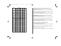 112
112
-
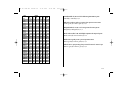 113
113
-
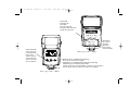 114
114
-
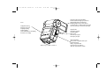 115
115
-
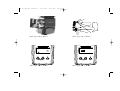 116
116
-
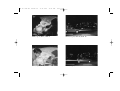 117
117
-
 118
118
-
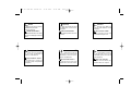 119
119
-
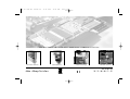 120
120


Metz MECABLITZ 44 AF-4 El manual del propietario
- Categoría
- Flashes de la cámara
- Tipo
- El manual del propietario
- Este manual también es adecuado para
en otros idiomas
- français: Metz MECABLITZ 44 AF-4 Le manuel du propriétaire
- italiano: Metz MECABLITZ 44 AF-4 Manuale del proprietario
- English: Metz MECABLITZ 44 AF-4 Owner's manual
- Deutsch: Metz MECABLITZ 44 AF-4 Bedienungsanleitung
- Nederlands: Metz MECABLITZ 44 AF-4 de handleiding
Artículos relacionados
-
Metz mecablitz 44 AF-4 Olympus El manual del propietario
-
-
-
-
-
-
-
-
Metz mecablitz 48 AF-1 digital Pentax El manual del propietario
-