GE HVM1540DM2WW Guía de instalación
- Categoría
- Microondas
- Tipo
- Guía de instalación

Installation
Instructions
Abovethe
CooktopOven
JVM1540
HVM1540
JNM1541
Questions?call 800.GE.CARES(800.432.2737)orVisit our Website at:ge.COm ]
BEFORE YOU BEGIN
Read these instructions completely and carefully.
• IMPORTANT - S_ve_h_s_
instructions for local inspector's use.
• IMPORTANT - Observe_,ll
governing codes and ordinances.
• Note to Installer - Besure to leave these
instI_ucfions with the (_onsumei.
• Note to Consumer - Keep these instructions
foI fl_Ulre reference.
• Skill level - Installation of tiffs appliance requires
basic mechanical and elecuical skills.
• Proper installation is the responsibility of the installm.
• Product failure due to improper installation is not
covered under the X_rarranty.
MFI,31918601
49-40529
09-0GIR
READ CAREFULLY.
KEEP THESE iNSTRUCTiONS.

Installation Instructions
CONTENTS
General information
Important Safety Instructions .................................. 3
Electrical Requirements .......................................... 3
Hood Exhaust ...................................................... 4, 5
Damage--Shipment/Installation .............................. 6
Parts Included .......................................................... 6
Tools You Will Need ................................................ 7
Mounting Space ...................................................... 7
Step-by-step installation guide
Placement of Mounting Plate ............................ 8-10
Removing the Mounting Plate ...................... 8
Finding the Wall Studs .................................. 8
Determining Wall Plate I,ocafion .................. 9
Aligning the Wall Plate ................................ 10
Installation Types .............................................. 11-22
_ Outside Top Exhaust ............................ 12-14
Attach Mounting Plate to Wall ............ 12
Preparation of Top Cabinet ................ 13
Assemble and Install Adaptor. ............. 13
Mount the Oven ............................ 13, 14
Adjust the Exhaust Adaptor ................ 14
Connecting Ductwork .......................... 14
]_ Outside Back Exhaust ............................ 15-18
Preparing Rear Wall for
Outside Back Exhaust .......................... 15
Attach Exhaust Adaptor to
Oven Rear Panel .................................. 15
Attach Mounting Plate to Wall ............ 16
Preparation of Top Cabinet ................ 16
Adapting Blower for Outside
Back Exhaust .......................................... 17
Mount the Oven .................................. 18
[] Recirculating ........................................ 19-22
Attach Mounting Plate to Wall ............ 19
Preparation of Top Cabinet ................ 19
Adapting Blower for
Recirculafion ................................ 20, 21
Mount the Oven ............................ 21, 22
Insudling the Charcoal Filter. ............. 22
Before You Use Your Oven .................................. 23
2

Installation Instructions
IMPORTANT SAFETY iNSTRUCTiONS
This product requires a three-prong grounded outlet.
The installer Illust perfbrm a ground continuity check
on the power oudet box before beginning the
installation to insure that the outlet box is properly
grounded. If not properly grounded, or if the outlet
box does not meet electrical requirements noted
(under ELECTRICAL REQUIREMENTS), a qualified
electrician should be employed to correct any
deficiencies.
CAUTION:
For personal safety, remove
house fuse or open circuit
breaker before beginning
installation to avoid severe
or fatal shock injury.
w
CAUTION: Forpersonal safety, the mounting
surface must be capable of supporting the cabinet load,
in addition to the added weight of this 63-85 pound
product, plus additional oven loads of up to 50 pounds
or a total weight of 113-135 pounds.
CAUTI ON: For personal safety, this product
cannot be installed in cabinet arrangements such as an
island or a peninsula. It must be mounted to BOTH
a top cabinet AND a wall.
NOTE: For easier installation and personal safety, it is
recommended that two people install this product.
IMPORTANT--PLEASE READ CAREFULLY. FOR
PERSONAL SAFETY, THIS APPLIANCE MUST BE
PROPERLY GROUNDED TO AVOID SEVERE OR
FATAL SHOCK.
Insure proper
ground exists
before use
The power cord of this
appliance is equipped with
a three-prong (grounding)
plug which mates with
a standard three-prong
(grounding) wall receptacle
to minimize the possibility
of electric shock hazard
from this appliance.
You should have the wall receptacle and circuit checked
by a qualified electrician to make sure the receptacle is
properly grounded.
Where a standard two-prong wall receptacle is
encountered, it is very important to have it replaced
with a properly grounded three-prong wall receptacle,
installed by a qualified electrician.
DO NOT, UNDER ANY CIRCUMSTANCES, CUT,
DEFORM OR REMOVE ANY OF THE PRONGS
FROM THE POWER CORD. DO NOT USE WITH
AN EXTENSION CORD.
ELECTRICAL
REQUIREMENTS
Product rating is 120 volts AC, 60 Hertz, 14 amps and
1.60 ldlowatts. This product must be connecmd to a
supply circuit of the proper voltage and flequency.
Wire size must conform to the requirements of the
Nadona/Elecuical Gode or the prevailing local code
for this kilowatt rating. The power supply cord and
plug should be brought to a separam 15 to 20 ampere
branch circuit single grounded outlet. The oudet box
should be locamd in the cabinet above the oven. The
outlet box and supply circuit should be inst;dled by
a quafified elecuician and confbim to the National
Elecuica/Code or the prevailing local code.
3

Installation Instructions
HOOD EXHAUST
NOTE: Read these next two pages only if you plan to vent your exhaust to the
outside. If you plan to recirculate the air back into the room, proceed to page 6.
OUTSIDE TOP EXHAUST (EXAMPLE ONLY)
The following chart describes an example of one possible
ductwork installation.
EQUIVALENT NUMBER EQUIVALENT
DUCT PIECES LENGTH x USED = LENGTH
RoofCap
12Ft.StraightDuct
(6" Round)
Rectangular-to-Round
TransitionAdaptod
24Ft. x (1)
12Ft. x (1)
5 Ft. x (1) =
24Ft.
12Ft.
5 Ft.
Equivalent lengths of duct pieces are based on actual tests and
reflect requirements for good venting performance with any vent hood.
Total Length = 41 Ft.
*IMPORTANT: If a rectangular-to-round u ansition adaptor is used, the bottom comers of the damper will
have to be cut to fit, using the tin snips, in order to allow flee movement of the dampeL
OUTSIDE BACK EXHAUST (EXAMPLE ONLY)
The following chart describes an example of one possible
ductwork installation.
DUCT PIECES
EQUIVALENT
LENGTH* x
NUMBER
USED
Wall Cap
3 Ft.StraightDuct
3¼" x 10"Rectangular)
40Ft.
3 Ft.
(1)
(1)
EQUIVALENT
LENGTH
40Ft.
3 Ft.
(_ 90° Elbow 10Ft. x (2) = 20Ft.
Equivalentlengthsof ductpiecesarebasedonactualtestsand
reflectrequirementsforgoodventingperformancewith anyvent hood.
Total Length = 63 Ft.
NOTE: For back exhaust, care should be taken to align exhaust with space between studs, or wall should be prepared
at the time it is constructed by leaving enough space between the wall studs to accommodate exhaust.
4

Installation Instructions
NOTE: If you need to install ducts, note that the total
duct length of 3¼"x 10" rectangular or 6" diameter
round duct should not exceed 120 equivalent feet.
Outside ventilation requires a HOOD EXHAUST DUCT.
Read the following caIefldly.
NOTE: It is important that venting be installed using
the most direct route and with as few elbows as possible.
This ensures clear venting of exhaust and helps prevent
blockages. Also, make sure dampers swing freely and
nothing is blocking the ducts.
Exhaust connection:
The hood exhaust has been designed to mate with a
standard 3¼" x 10" rectangular duct.
If a round duct is required, a rectangular-to-round
uansition adaptor must be used. Do not use less than
a 6" diameter duct.
Maximum duct length:
For satisfactory air movement, the total duct length of
3¼"x 10" rectangular or 6" diameter round duct should
not exceed 120 equivalent feet.
Elbows, transitions, wall and roof caps,
etc., present additional resistance to airflow and are
equivalent to a section of smdght duct which is longer
than their actual physical size. When calcula6ng the
total duct length, add the equivalent lengths of all
uansi6ons and adaptors plus the length of all suaight
duct sections. The chart below shows you how to
calculate total equivalent ductwork length using the
approximate feet of equivalent length of some
typical ducts.
DUCT PIECES
G
O
m
Rectangular-to-Round
TransitionAdaptoP
Wall Cap
90° Elbow
45° Elbow
90° Elbow
45° Elbow
RoofCap
StraightDuct6" Roundor
3¼" x 10"Rectangular
EQUIVALENT
LENGTH
5Ft.
40 Ft.
10 Ft.
5 Ft.
25 Ft.
5 Ft.
24 Ft.
1Ft.
* IMPORTANT: If a rectangular-to-round transition
adaptor is used, the bottom corners of the damper
will have to be cut to fit, using the tin snips, in order
to allow ti"ee movement of the damper.
NUMBER
x USED
x ( )
x ( )
x ( )
x ( )
x ( )
x ( )
x ( )
x ( )
Total Ductwork
EQUIVALENT
= LENGTH
=
=
=
=
=
=
=
=
==
Equivalent lengths of duct pieces are based on actual tests
and reflect requirements tbr good venting pertbrmance with
_l_) r veIlt tlood,
5
Ft.
Ft.
Ft.
Ft.
Ft.
Ft.
Ft.
Ft.
Ft.

Installation Instructions
DAMAGE - SHIPMENT/
iNSTALLATiON
• If the unit is damaged in shipment, return the
unit to the store in which it was bought for repair
or replacement.
• If the unit is damaged by the customer, repair or
replacement is the responsibility of the customer.
• If the unit is damaged by the installer (if other
than the customer), repair or replacement must
be made by arrangement bet_,veen customer and
installer.
PARTS INCLUDED
HARDWARE PACKET
PART
/
J
WoodScrews
(1A"x2")
ToggleBolts(and
wing nuts)(Y4"x3")
Self-aligningMachine
Screws(W'-28 x3W')
NylonGrommet
(formetalcabinets)
Metal Screws
(Y¢'x _k")
PowerCordStrap
(plastic)
QUANTITY
2
1black
2 bronze
You will find the installation hardware contained in
a packet with the unit. Check to make sure you have
all these parts.
NOTE: Some extra parts are included.
PARTS INCLUDED
ADDITIONAL PARTS
PART
TOPCABINETTEMPLATE
REAR
WALL
TEMPLATE
{NSTALL_ON
INSTRucTIoNs
TopCabinet
Template
RearWall
Template
installation
instructions
Separately
Packed
Grease
Filters
Charcoal
Filter
(onsome
models)
m
QUANTITY
1
1
1
2
1
Exhaust 1
Adaptor
Damper 1
6

Installation Instructions
TOOLS YOU WILL NEED
# 1 and#2 Phillipsscrewdriver
Pencil
Ruleror tapemeasure
aightedge
Carpentersquare
(optional)
Tinsnips(forcutting
damper,if required)
Gloves
Scissors
(tocuttemplate,if necessary)
Saw(saber,holeor keyhole)
Electricdrill with ¾g', 7½s',3_-,
_½"and%" drillbits
8
Studfinder er
Hammer (optional)
Fillerblocksor scrap
woodpieces,if needed
fortop cabinetspacing
(usedonrecessedbottom
cabinetinstallationsonly)
Safety goggles
Level
Duct and masking tape
MOUNTING SPACE
Iit UtlIII
NOTE:Maximumcabinetdepthis 13".
L_
66" or more
from the floor
to the top of
the oven
Bottom edge of
cabinet needs to
be 30" or more
from the cooking
surface
Backsplash
NOTES:
• The space between the cabinets must be 30"
wide and flee of obstructions.
• If the space between the cabinets is greater
than 30", a Filler Panel Kit mW be used to fill
in the gap between the oven and the cabinets.
Your Owner's Manual contains the kit number
for your model.
• This oven is for installa6on over ranges up to
,t6" wide.
• If you are going to vent your oven to the outside,
see Hood Exhaust Section for exhaust duct
preparation.
• When installing the oven beneath smooth, fiat
cabinets, be careful to follow the instructions
on the top cabinet template for power cord
clearance.
7

Installation Instructions
I PLACEMENT OF THE MOUNTING PLATE
REMOVING THE OVEN FROM
THE CARTON/REMOVING THE
MOUNTING PLATE
%
[]
Remove the turntable, installation instructions,
filters, exhaust adaptoi; dampe_; shelf and the
small hardware bag. Do not remove the Styrofoam
protecting the flont of the oven.
Fold back all 4 carton flaps flflly against carton
sides. Then careflflly roll the oven and carton over
onto the top side. The oven should be resting in
the Styrofoam.
[]Pull the carton lap and off the oven.
[]
The mounting plate is attached to the back of the
oven. Remove the two screws holding it to the oven.
The plate will be used as the rear wall template and
for mounting the oven to the wall.
[] Set the oven upright. Remove and properly discard
plastic bags and Styrofoam.
Open tim oven door and remove any packing
material, if present, from inside the oven.
I-_ FINDING THE WALL STUDS
l i
Wall
Studs
i
Centesimi
_i_ Find the studs, using one of the following
methods:
A. Stud finder - a magnetic device which
locates nails.
OR
B. Use a hammer to tap lightly across the
mounting surface to find a solid sound.
This will indicate a stud location.
After locating the stud(s), find the center by
probing the wall with a small nail to find the
edges of the stud. Then place a mark halfk,vay
between the edges. The center of any adjacent
studs should be 16" or 24" fiom tiffs mark.
_Draw a line down the center of the studs.
THE OVEN MUST BE CONNECTED TO AT LEAST
ONE WALL STUD.
8

Installation Instructions
DETERMINING WALL PLATE LOCATION UNDER YOUR CABINET
Plate position - beneath flat bottom
cabinet
Plate position - beneath framed recessed
cabinet bottom
MountingPlateTabs
theCabinet
Bottom
Mounting Plate Tabs
Touching the Back
'-. Frame
...
At least 30", upto 36"
30" to Cooktop
Plate position - beneath recessed bottom
cabinet with front overhang
MountingPlatewith
TabsBelowCabinet
Bottomthe Same
Distanceasthe Front
OverhangDepth
\
30" to Cooktop
÷
Your cabinets may have decorative uim that interferes
with the oven installation. Remove the decorative uim
to install the oven properly and to make it level.
THE OVEN MUST BE LEVEL.
Use a level to make sure tim cabinet bottom is level.
If tim cabinets have a flont overhang only, with no
back or side flame, install the mounting plate down
the same distance as the flont overhang depth. This
will
[]
%
%
keep the oven level.
Measure the inside depth of the flont overhang.
Draw a horizontal line on the back wall an equM
distance below the cabinet bottom as the inside
depth of the front overhang.
For this type of installation wkh front overhang only,
align the mounting robs with this horizontal line, not
touching the c_fl)inet bottom as described in Stop D.
9

Installation Instructions
ALIGNING THE WALL PLATE
,\
\
\
\
\A /
Hole
\\
\
\
I
I
HoleC_
CAUTION: Wear gloves
to avoid cutting fingers on
sharp edges.
I i
ro I " _
. Draw a Vertical
LineonWall i
i [i
I<-ifrom Center of iL
ii i Top Cabinet
J
• [
i I / 1i
AreaE I
i
/
/
------------Hole B
/
HoleD
NOTE: Appearance and
shape of the mounting
plate uray vary from your
model.
_Draw a vertical line on the wall at the center of the 30"
wide space.
_Use the mounting plate as the template fox the rear
wall. Place the mounting plato on tim wall, making
sure that the robs are touching the bottom of the
cabinet or the level line drawn in Step C for cabinets
with front overhang. Line up the notch and center line
on the mounting plate to the center line on the wall.
While holding the mounting plate with one hand,
draw circles on the wall at holes A, B, C and D (see
illusuafion above/actual plate marked with anows).
Four holes must be used for mounting.
NOTE: Holes C and D are inside area E. If neidler
C nor D is in a stud, find a stud somewhere in area E
and draw a fifth circle to line up with die stud. It is
important to use at least one wood screw mounted
firmly in a stud m support the weight of the oven.
Set the mounting plate aside.
Drill holes on the circles. If there is a stud, drill a _X_/'
hole for wood screws. Fox holes that don't line up with
a stud, drill a %" hole for toggle bolts.
NOTE: DO NOT MOUNT THE PLATE
AT THIS TIME.
10

Installation Instructions
INSTALLATION TYPES
This oven is designed for adaptation to the following three
types of ventilation:
A. Outside Top Exhaust (Vertical Duct)
B. Outside Back Exhaust (Horizontal Duct)
C. Recirculating (Non-Vented Ducdess)
(Choose A, B or C)
NOTE: This oven is shipped assembled for Outside Top
Exhaust (except for non-vented models). Select the type
of ventilation required for your installation and proceed
to that section.
OUTSIDE TOP EXHAUST
(VERTICAL DUCT)
I--_ OUTSIDE BACK EXHAUST
(HORIZONTAL DUCT)
/
RECIRCULATING
(NON-VENTED DUCTLESS)
On models shipped for
non-vented exhaust, a
disposable charcoal filter is
included with the oven and
needs to be installed to help
remove smoke and odors.
On models shipped for
outside top exhaust, a
Charcoal Filter Accessory Kit
is required for the non-vented
exhaust. (See your Owner's
Manual for the kit numbeL)
11

Installation Instructions
OUTSIDE TOP EXHAUST (Vertical Duct)
INSTALLATION OVERVIEW
A1. Attach Mounting Plate to Wall
A2. Prepare Top Cabinet
A3. Install Adapter
A4. Mount Oven
A5. Adjust Exhaust Adaptor
A6. Gonnect Ductwork
I-_ ATTACH THE MOUNTING
PLATE TO THE WALL
=_===
Attach the plate to the wall using toggle bolts. At least
one wood screw must be used to attach the plate to a
wall stud.
[]Remove the toggle wings flom the bolts.
[]Insert the bolts into the mounting plate
through the holes designated to go into d_Twall
and reatmch the toggle wings to :_" onto each bolt.
To use toggle bolts:
Spacingfor Toggles
MoreThanWall
+l_-_i_--Thickness
Wings
Mounting
Plate_.
BoltEnd
_ Place the mounting plate against the wall and
insert tim toggle wings into the holes in the wall to
mount the plate.
NOTE: Before tightening toggle bolts and wood
screw, make sure the robs on the mounting plate
touch the bottom of the cabinet when pushed
flush against the wall and that the plate is properly
centered under the cabinet.
CAUTION: Be carefifl to avoid pinching fingers
between the back of the mounting plate and the wall.
_ Tighten all bolts. Pull the plate away flom the wall
to help tighten the bolts.
12

Installation Instructions
I-_ USE TOP CABINET TEMPLATE
FOR PREPARATION OF TOP
CABINET
You need to drill holes for the top support screws, a
hole large enough for tim power cord to fit through,
and a cutout large enough for tim exhaust adaptor.
• Read tim instructions on the TOP CABINET
TEMPI ,ATE.
• Tape it underneath tim top cabinet.
• Drill the holes, following tim instructions on tim
TOP CABINET TEMPI,ATE.
CAUTION: Wear safety goggles when drilling holes
in tim cabinet bottom.
ASSEMBLE AND
INSTALL ADAPTOR
Damper
g Exhaust
Adaptor
i_ BlowerPlate
__7 Backof
oven
NOTE: On some models, the exhaust adaptor and
damper assembly may aheady be assembled to the oven.
[]Place the oven in its upright position, with the top
of the unit facing tap.
NOTE: Make sure the blower fan blades are visible
and are pointing up.
_ Insert the tabs on each side of the damper into the
holes at the inside rear of the adaptor.
_ Attach the exhaust adaptor to tim blower plate with
the t_,vobronze metal screws provided.
Make sure that the damper pivots easily before
mounting oven.
You will need to make adjttstments to assure proper
alignment with your house exhaust duct after the
oven is installed.
13
I-_ MOUNT THE OVEN
FOR EASIER INSTAI,I,ATION AND PERSONAl,
SAFETY, WE RECOMMEND THAT TWO PEOPLE
INSTALL THIS OVEN.
IMPORTANT: Do not grip or use handle
during installation.
NOTE: If your cabinet is metal, use the nylon
grommet around the power cord hole to prevent
cutting of tim cord.
NOTE: We recommend using fillet blocks if the
cabinet flont hangs below the cabinet bottom shelf.
IMPORTANT: If filler blocks are not
used, case damage may occur from over
tightening screws.
NOTE: When mounting the
oven, thread power cord
through hole in bottom
of top cabinet. Keep it fight
ttnoughout Steps 1-3.
Do not pinch cord or lift
oven by pulling cord.
I,iff oven, tilt it
forward and hook
slots at back bottom
edge onto two lower
robs of mounting
plate.
\
_ Rotate flont of
oven
up against cabinet
bottom.

Installation Instructions
MOUNT THE OVEN (continued)
CabinetFront
CabinetBottomShelf
FillerBlock
T quivalent
to Depth
ofCabinet
Recess
Self-AligningScrew
OvenTop
[]Attach the oven to the top cat)inet t)y inserting
2 self'aligning screws through outer top cabinet
holes. Turn two full turns cm each screw. Be sure
to keep power cord tight. Be careful not to pinch
the cord, especially when mounting flush to
bottom of cabinet.
[] Tighten the two screws to the top of the oven
completely. (While tightening screws, hold the
oven in place against the wall and the top cabinet.)
[] Install grease filters. See the Owner's Manual
packed with the oven.
ADJUST THE EXHAUST
ADAPTOR
Open the top cabinet and adjust the exhaust adaptor
to connect to the house duct.
Damper
Backof
_S Oven
I-_ CONNECTING DUCTWORK
HouseDuct
_ Extend the house duct down to connect to
the exhaust adaptoi.
Seal exhaust duct joints using duct rope.
14

Installation Instructions
OUTSIDE BACK EXHAUST (Hori-ontalDuct)
INSTALLATION OVERVIEW
B1. Prepare Rear Wall
B2. Attach Exhaust Adaptor to
Wall Plate
B3. Attach Mounting Plate
to Wall
B4. Prepare Top Cabinet
BS. Adjust Blower
B6. Mount tile Oven
r_ PREPARING THE REAR WALL
FOR OUTSIDE BACK EXHAUST
You need to cut an opening in tile rear wall for
outside exhaust.
[]Read tile instructions on tile REAR WAI,I,
TEMPI ,ATE.
[]Tape it to tile rear wall, lining tap with tile holes
previously drilled for holes A and B in tile wall
plate.
_Cut tile tile instructions of tileopening, following
REAR WAI,I, TEMPI,ATE.
ATTACH THE EXHAUST
ADAPTOR TO THE OVEN REAR
PANEL
_Unscrew and remove tile exhaust adaptor
assembly flom tile top of tile oven.
I
_Atmch tile exhaust adaptor to tile oven rear
panel by sliding it into the guides at the top
center of the back of tile oven.
ExhaustAdaptor
Guide--__
o o
Damper
_.w/_ _ (hingesideup)
_"'"__ Guide
Locking
Tabs
Push in securely until it is in tile lower locking tabs.
Take care to assure tile damper hinge is installed so
that it is at tile top and that tile damper swings fieely.
15

Installation Instructions
I-_ ATTACH THE MOUNTING
PLATE TO THE WALL
Attach the plate to the wall using toggle bolts. At least
one wood scIew Illtlst be used to attach the plate to a
wall stud.
[]Remove the toggle wings flom the bolts.
[]Insert the bolts into the mounting plate through
the holes designated to go into drDvall and reatmch
the toggle wings to :_" onto each bolt.
To use toggle bolts:
Spacingfor TogglesMore
-_l-,--!-,_ ThanWall Thickness
M .. IToggleWings
ountmg IIl'.,.li /Toggle II I.:1
Plate_lll,:.::ll.t_ Bolt II I::K
Ini: I-<-Wall In u,l I
BoltEnd
[]Place the mounting plate against the wall and
insert the toggle wings into the holes in the wall
to i_lotlnt the plate.
NOTE: Before tightening toggle bolts and wood
screw, make sure the tabs on the mounting plate
touch the bottom of the cabinet when pushed flush
against the wall and that the plate is properly
centered under the cabinet.
CAUTION: Be careflfl to avoid pinching fingers
between the back of the mounting plate and the wall.
[]Tighten all bolts. Pull the plate away flom the wall
to help tighten the bolts.
USE TOP CABINET TEMPLATE
FOR PREPARATION OF TOP
CABINET
You need to drill holes for the top support screws and
a hole large enough for the power cord to fit through.
• Read the instructions on the TOP CABINET
TEMPI_ATE.
• Tape it underneath the top cabinet.
• Drill the holes, following the instiuctions on the
TOP CABINET TEMPLATE.
CAUTION: Wear safety goggles when drilling boles in
the cabinet bottom.
16

Installation Instructions
I-_ ADAPTING BLOWER FOR
OUTSIDE BACK EXHAUST
_i_ Remove the two screws that hold the blower plate
and remove the screw holding the blower motor
to the oven. Slide blower plate flom under its
retaining flange.
y
Retaining ? "
Flange"_K_O__- BlowerPlate
[]Carefully the blower unit. The wirespull
otlt
will extend far enough to allow you to adjust
the blower unit.
Backof
Oven
[]Rotate blower unit counterclockwise 180 °.
BeforeRotation
Backof
Oven
After Rotation
Backof
Oven
[]Roll the blower unit 90 ° so that fan blade
openings are facing out the back of the
oven.
BeforeRollin_
--__ After Rolling
Oven
Backof
Oven
[_ Place the blower unit back into the opening.
iiii_i_!_i_i_!iiiii!i!i_!_!_iii_ii_!_!ii!ii_!i_i_ii_i!_i!ii_ii!ii_iiiiiiiiiii_i!_i!_i!_i!_i!_i!_i!_i_i!i_
CAUTION: Do not pull or stretch the blower
unit wiring. Make sure the wires are not pinched.
NOTE: The blower unit exhaust openings should
match exhaust openings on rear of oven.
Replace the blower plate in the same position
as before and replace the screws for the
blower plate and blower illotor.
BlowerPlateScrews
BlowerPlate
_t--_J BackofOven
,,_-'__'_._------ BlowerMotorScrew
17

Installation Instructions
I-_ MOUNT THE OVEN
FOR EASIER INSTALLATION AND PERSONAL
SAFETY, WE RECOMMEND THAT TWO PEOPLE
INSTALL THIS OVEN.
IMPORTANT: Do not grip or use handle
during installation.
NOTE: If your cabinet is metal, use tim nylon
grommet around the power cord hole to prevent
cutting of the cord.
NOTE: We recommend using filler blocks if the
cabinet flont hangs below the cabinet bottom shelf.
IMPORTANT: If filler blocks are not
used, ease damage may occur from over
tightening screws.
NOTE: When mounting
the oven, thread power
cord through hole in
bottom of top cabinet.
Keep it tight throughout
Steps 1-3. Do not pinch
cord or lift oven by
pulling cord.
[] I,iff oven, tilt it
forward and hook
slots at back bottom
edge onto two lower
robs of mounting plate.
\
[]Rotate flont of oven up
against cabinet bottom.
Cabinet Front
Cabinet Bottom Shelf
Filler Block
-_ Equivalent
to Depth
ofCabinet
Recess
Self-Aligning Screw
OvenTop
[] Attach the oven to the top cabinet by inserting
2 self-aligning screws through outer top cabinet
holes. Turn two full turns on each screw. Be sure
to keep power cord tight. Be careful not to pinch
the cord, especially when mounting flush to
bottom of cabinet.
[] Tighten the two screws to the top of the oven
completely. (While tightening screws, hold the
oven in place against the wall and the top
cabinet.)
}?
//c
_ Install grease filters. See the Owner's Manual
packed with the oven.
18

Installation Instructions
RECIRCULATING (Non-Vented Ductless)
INSTALLATION OVERVIEW
C1. Attach Mounting Plate to Wall
C2. Prepare Top Gabinet
C3. Adjust Blower
C4. Mount the Oven
C5. Install Gharcoal Filter
I-_ ATTACH THE MOUNTING
PLATE TO THE WALL
Attach the plate to the wall using toggle bolts. At
least one wood screw must be used to attach the
plate to a wall stud.
_ Remove the toggle wings flom the bolts.
_ Insert tim bolts into the mounting plate through
the boles designated to go into d_ywall and
reatmch the toggle wings to ¾" onto each bolt.
To use toggle bolts:
Spacingfor Toggles
MoreThanWall
+l_,_i_Thickness
M itl-oggleWings
ountmg II1,11 / Toggle II I'+t
Plate..lll_::l.._Bolt,_\11I!:i_
II,' :l<-Wall l! ,:l I
BoltEnd
_ Place the mounting plate against the wall and
insert the toggle wings into the holes in the wall to
mount the plate.
NOTE: Before tightening toggle bolts and wood
screw, make sure the robs on the mounting plate
touch the bottom of the cabinet when pushed flush
against the wall and that the plate is properly
centered under the cabinet.
CAUTION: Be careflfl to avoid pinching fingers
between the back of the mounting plate and the wall.
_ Tighten all bolts. Pull the plate away flom the wall
to help tighten the bolts.
USE TOP CABINET TEMPLATE
FOR PREPARATION OF TOP
CABINET
You need to drill holes for the top support screws and
a hole large enough for the power cord to fit through.
-275.........
• Read the instructions on the TOP GABINET
TEMPI ,ATE.
• Tape it underneath the top cabinet.
• Drill the holes, following the instructions on the
TOP CABINET TEMPI,ATE.
CAUTION: Wear safeb, goggles when drilling holes
in the cabinet bottom.
19

Installation Instructions
ADAPTING BLOWER
FOR RECIRCULATION
NOTE: The exhaust adaptor with damper is not
needed for recirculating models. You may want to
save them for possible flmne use.
_!_ Remove and that hold blower andplate
save screws
blower unit to the oven.
BlowerPlateScrews
BlowerPlate
' ' Backof Oven
_e--- BlowerMotorScrew
[]Slide the blower plate flom under its retaining
flange and lift it off\
Retaining
BlowerPlate
Carefull), pull out the blower unit The wires
[] . " ...... .
wdl extend far enough to allow you to adjust the
blower unit.
[]Roll the blower unit 90 ° so that fan blade openings
are facing toward the flont of the oven.
R011
20

Installation Instructions
ADAPTING BLOWER FOR
= =
RECIRCULATION (continued)
_] Place the blower unit back into the opening°
CAUTION: Do not pull or stretch the blower unit
wiring. Make sure the wires are not pinched.
[] Replace blower plate and replace screws for blower
plate and blower motor removed in Step 1.
Blower Plate Screws
BlowerPlate
,j
i Backof Oven
---- BlowerMotorScrew
I-_ MOUNT THE OVEN
FOR EASIER INSTALIzATION AND PERSONAL
SAFETY, WE RECOMMEND THAT TWO PEOPLE
INSTALL THIS OVEN.
IMPORTANT: Do not grip or use handle
during installation.
NOTE: If your cabinet is metal, use tim nylon
grommet around the power cord hole to prevent
cutting of the cord.
NOTE: We recommend using fillet blocks if the
cabinet flont hangs below the cabinet bottom shelf.
IMPORTANT: If filler blocks are not used,
case damage may occur from over tightening
screws.
NOTE: When mounting
the oven, thread power
cord through hole in
bottom of top cabinet.
Keep it fight ttuoughout
Steps 1-3. Do not pinch
cord or lift oven by
pulling cord.
I,ift oven, tilt it
forward and hook
slots at back bottom
edge onto two lower
tabs of mounting plate.
_ Rotate flont of oven
up against cabinet
t)ottom.
CabinetFront
CabinetBottomShelf
Block
Equivalentto Depth
f CabinetRecess
Self-AligningScrew
OvenTop
21

Installation Instructions
I-_ MOUNT THE OVEN
(continued)
_Atmch the oven to the top cabinet by inserting
2 self-aligning screws through outer top cabinet
holes. Turn two full turns on each screw. Be sure
to keep power cord tight. Be careful not to pinch
the cord, especially when mounting flush to
bottom of cabinet.
[] Tighten the two screws to the top of the oven
completely. (While tightening screws, hold
the oven in place against the wall and the top
cabinet.)
)
[] Install grease filters. See the Owner's Manual
packed with the oven.
I-_ WHEN REPLACING THE
CHARCOAL FILTER
If the model is not vented to the outside, the air will
be recirculated through a disposable charcoal filter
that helps remove smoke and odors.
The charcoal filter should be replaced when it is
noticeably dirty or discolored (usually after 6 to
12 months, depending on hood usage). See your
Owner's Manual for the filter kit number.
To replace the charcoal filter:
[] Remove 4 screws on top of grille using a Phillips
screwdriveL
_Open the dooL
[] Remove the grille.
L L_: i Charcoal
Filter
I
_ Slide the old filter to the fiont of the and
oven
remove it.
_ Remove plastic and other outer wrapping flom
the new filter and install the new filteL _qlen
properly installed, the wire mesh of the filter
should be visible flom the flont.
Replace the grille and the 4 screws.
_ Close the door.
Insert mesh-side up
22

Installation Instructions
BEFORE YOU USE YOUR
Make sure the oven has been installed
according to instructions.
OVEN
r_7] Read the Owner's Manual.
[_ Remove all packing material flom the oven.
_ Install turntable and wheeled ring in cavity. ]
Replace house fuse or mrn breaker back on.
KEEP INSTALLATION INSTRUCTIONS
FOR THE LOCAL INSPECTOR'S USE.
Plug power cord into a dedicated 15 to 20 amp
electrical outlet.
i
,f
23

Prin[ed in China

Inst.rucciones
de instalaclon
Hornopara colocar
encima de la estufa
JVM1540
HVM1540
JNM1541
J gPreguntas? Llame 800-GE-CARES(800-432-2737)oxdsite nuestra p_igina en la red en: ge.com i
ANTES DE EMPEZAR
Lea estas instrucciones completa y cuidadosamente.
• IMPORTANTE - G.__leesters
instrucciones pare el uso del inspector local.
IMPORTANTE - C.mplaco._o_los
los cddigos y ordenanzas gubernamenmles.
• Nota para el instalador - Asegdresede dejar
esms insuucciones con el consumidoL
• Nota para el consumidor - Guarde estas
insu_ucciones para flmlra referencia.
• Nivel de destrezas - I,a instalacidn de este aparato
requiere de desuezas bdsicas de mecdnica y elecuicidad.
• Ia instalacidn apropiada es responsabilidad del
instaladoL
• Ia falla del producm debido a una instalacidn
inapropiada no est5 cubierm pot la gamntfa.
MFI_31918601
49-40529
09-0GIR
LEA CUIDADOSAMENTE.
GUARDE ESTAS INSTRUCCIONES.

Instrucciones de instalaci6n
CONTENIDO
Informacion general
Instrucciones de seguridad importantes .................. 3
Requisitos el6ctricos ................................................ 3
Campana de escape .............................................. 4, 5
Dafios - Envio / Instalaci6n .................................... 6
Partes incluidas ........................................................ 6
Herramientas que necesitarfi .................................... 7
Espacio de montaje .................................................. 7
Guia de instalacion paso por paso
C6mo colocar el plato de montaje...................... 8-10
G6mo remover el plato de mont_je .................. 8
G6mo enconuar madera s61ida en la pared ...... 8
G6mo determinar la localizaci6n de la placa
de la pared ........................................................ 9
G6mo alinear la placa de la pared .................. 10
Tipos de instalaci6n .......................................... 11-22
_ Escape superior exterior. 12-14
G6mo adherir la placa de mont_je
a la pared ................................................ 12
Preparaci6n del gabinete superior .......... 13
Ensambl_je e insmlaci6n del adapmdor ..18
G6mo montar el homo ...................... 13, 14
G0mo _jusmr el adapmdor de escape ...... 14
G6mo conecmr la red de conductos ........ 14
_]_ Escape posterior ..........................
exteino 15-18
G6mo preparar la pared posterior
para el escape posterior exterior. ............. 15
Fije el adapmdor de la campana
exuactora al panel posterior del homo ..15
G6mo adherir el plato de
mont_{je a la pared .................................. 16
G6mo preparar el gabinete superior. ....... 16
G6mo adaptar el calefactor para
el escape exterior posterior ...................... 17
G6mo montar el homo ............................ 18
_ Rechculaci6n ............................................ 19-22
G6mo adhmir el plato de
mont_je a la pared .................................. 19
C6mo preparar el gabinete superior. ....... 19
C6mo adaptar el calefactor
para la recirculaci6n .......................... 20, 21
Cdmo monmr el homo ...................... 21, 22
C6mo insmlar el filtro de carbonilla ........ 22
Antes de comenzar a usar su horno ...................... 23
2

Instrucciones de instalaci6n
INSTRUCCIONES DE SEGURIDAD IIVIPORTANTES
Este producto requiere un tomaconJente el_cuJco de tres
paras conecmdo a fierm. E1 insm/ador debe llevar a cabo
una inspeccidn de confinuidad a tierm en la c_ja el_ctrica
antes de comenzar la insta/acidn pare asegumr que la
c_ja tomacorrienm estli conecmda a tierra de manem
apropiada. N no lo ester, o si el tomacorrienm no cumple
con los requisitos el_ctficos indicados (b_jo la seccidn
REQUISITOS ELt_CTRICOS), se deberfi recurrir a un
td.cnico ca/ificado pare corregir cua/quier deficiencia.
PRECAUCION:
Para seguridad personal,
remueva el fusible de la
easa o abra el interruptor de
circnito antes de comenzar
la iustalacidn para evitar
descargas el6ctricas severas
o fatales.
PRECAUCION: En pos de la seguridad
personal, la superfide de montaje debe ser capaz de
soportar la carga del gabinete, ademRs del peso adicional
(de 63 a 85 libras) de este producto, mils las cargas
adicionales del horno de basra 50 libras otm peso total
entre 113 y 135 libras.
PRECAUCION: E.posaela
personal, este producto no puede ser instalado en
sistemas de gabinetes tales como los llamados "islas" o
"peninsulas". !_ste debe ser montado tanto a un gabinete
superior como a una pared.
NOTA: Para una instalaci6n mRS fficil yen pos de la
seguridad personal, se recomienda que dos personas
iustalen este producto.
IMPORTANTE:
POR FAVOR, LEA CUIDADOSAMENTE. EN POS DE
LA SEGURIDAD PERSONAL, ESTE APARATO DEBE
SER CONECTADO A TIERRA APROPIADAMENTE
PAR& EVITAR DESCARGAS SEVERAS O FATALES.
Aseguresede
queexlsteuna
conexi6na
tierra apropiada
antesdel uso
E1 cable el6ctrico de este
aparato estfi equipado con
un enchufe de tres patus
(con conexidn a tierra),
lo cual reqniere que el
mismo encaje con un
tomacorriente para tres
paras (con conexidn a tierra)
de pared para minimizar
la posibilidad de descargas
el6ctricas.
Deber_ hacer que un t_cnico calificado iuspecdone el
tomacorriente de pared y el circuito para asegurarse de
que el tomaeorriente est_ conectado a tierra de manera
apropiada.
Donde usted encuentre un tomacorriente estfindar de
dos paras, es muy importante que haga que el mismo se
cambie por uno de tres paras apropiadamente conectado
a fierra, iustalado por un electricista calificado.
BAJO NINGUNA CIRCUNSTANCIA NO CORTE,
DEFORME, O REMUEVA NINGUNA DE LAS PATAS
DEL CABLE ELt_CTRICO. NO LO USE CON UNA
EXTENSION ELECTRICA.
REQUISITOS E CTRICOS
La clasificacidn del producto es de 120 ratios CA (AC),
60 hertz, 14 amperios, y 1,60 ldlovafios. Esm producto
debe esmr conecmdo a un circuito de suminisuo del
volt_ie y flecuencia apropiados. E1 tamafio del a/ambre
debe confbmm_e a los requisitos del NafionN Electric
Code o a/cddigo local en efecto para este fndice de
ldlovatios. E1 cable el_cuico de a/imenmcidn y el
inmrruptor debeFdn llevarse a un tomaconJenm dnico
conecmdo a fierra de 15 a 20 ampefios. Ia c_ja del
tomacorriente deberd esmr loca/izada en el gabinem
encima del homo. ia c_ja del tomacorriente debe set
insmlada pot un elecuicism ca/ificado y debe confbrma_e
a/National Electrical Code o a/cddigo local en efe.cto.
3

Instrucciones de instalaci6n
CAIVIPANA DE ESCAPE
NOTA: Lea las siguientes dos pfiginas solamente si planea ventilar el escape hacia el exterior.
Si por el contrario planea recircular el aire de vuelta hacia el salrn, continfie en la pfigina 30.
ESCAPE SUPERIOR EXTERNO (EJEMPLO SOLAMENTE)
La siguiente mbla describe un ejempIo de una posible
instalaci6n de red de conductos.
PARTESDEL CONDUCTO
Tapadeltecho
Conductorectode 12pies
(redondode 6")
i_ Adaptadordetransici0n
derect_inguloa redondo_
LONGffUD NOMERO LONGffUD
EQUIVALENTE x USADO = EQUIVALENTE
24pies x (1)
12pies x (1)
5 pies x (1)
24pies
12pies
5 pies
LaIongitudde laspartesde losconductosequivalentesest8basadaen pruebasrealesy reflejanlos
requisitosparaIograrunabuenaventilaciOnconcualquiercampanade escape.
Longitud total = 41 pies
*IMPORTANTE: Si se usa tm adaptador de transici6n de rectdngulo a redondo, las es( uinas del fondo
del regulador de tiros deberdn cormrse para que enc_jen, usando las tijeras de corte para permitir el
movimiento libre del regulador de tiros.
LONGITUD
EQUIVALENTE
ESCAPE POSTERIOR EXTERNO (EJEMPLO SOLAMENTE)
La siguiente mbla describe un ejemplo de una posible
insmlaci6n de red de conductos.
LONGITUD N01VIERO
PARTESDELCONDUCTO EQUIVALENTE x USADO =
_ Tapadepared 40pies x (1) = 40pies
Conductorectode3 pies 3pies x (1) = 3 pies
(rectangularde31/4"x 10")
Cododeg0° 10pies x (2) = 20pies
LaIongituddelaspartesde losconductosequivalentesestabasadaenpruebasrealesyreflejanlos
requisitosparaIograrunabuenaventilaciOnconcualquiercampanadeescape..
Longitud total = 63 pies
NOTA: Para el escape posterior, se debe tenet cuidado al alinear el escape entre los espacios de los postes de vig'a de la pared,
o la pared deberfa ser preparada en el momento de su construcci6n dejando suficiente espacio entre los postes de viga de la
pared para acomodar el escape.
4

Instrucciones de instalaci6n
NOTA: Si usted necesim insmlar conducms, tenga
pendiente que la longitud total del conducto rectangular
de 3¼" x 10" o el conducto redondo de 6" de di_imetro
no debe sobrepasar 120 pies equivalentes.
La venfilaci6n externa requiere un CONDUCTO DE
CAMPANA DE ESCAPE. Lea lo siguiente cuidadosamente.
NOTAa Es impormnte que la venfilaci6n sea insmlada
usando la rum m_ts direcm y con la menor canfidad de codos
posible. Esm asegum la venfilacidn del escape y ayuda a
prevenir bloqueos. Tambi_n, eerddrese de que d regulador
de fifo pende libremente y nacla bloquea los eonduetos.
Conexiones de escape:
I;l campana de escape ha sido diseflada para enc_jar con
un conducm rectangular de 3¼" x 10" est:indaL
Si un conducm redondo es necesafio, se debe usar un
adapmdor de uansici6n de rectangular a redondo.
No use un eondueto menor de 6" de clifimetro.
PARTESDE CONDUCTO
&
i
O
J
LONGITUD
EQUIVALENTE
Longitud maxima del conducto:
Para lograr un movimiento satisfactorio del aire, la
longimd total del conducto rectangular de 3¼" x 10"
o el conducto redondo de 6" de didmeuo no debe
sobrepasar 120 pies equivalentes.
Los codos, transiciones, paredes y tapas
de techo, etc., presentan resistencia adicional al
flt{jo de aire y son equivalentes a una secci6n de
conducto recto el cual es rods largo que su tamafio fisico
real. Cuando calcule la longimd total del conducto,
agregue las longitudes equivalentes de todas las
uansiciones y adaptadores, m_s la longimd de todas
las secciones de conducto rectus. La tabla mds adelante
muesua c6mo puede calcular la longimd aproximada
de la red de conductos usando pies aproximados de
longitudes equivalentes de algunos conductos tipicos.
NOMERO
USADO
AdaptadordetransiciOnde
rectanguloa redondo_
Tapadepared
Codode90°
Codode45°
Cododeg0°
Codode45°
Tapadetecho
Conductorectode 6" redondo
o rectangularde3//4"x 10"
5pies
40 pies
10pies
5 pies
25 pies
5 pies
24pies
1pies
LONGITUD
EQUIVALENTE
pies
pies
pies
pies
pies
pies
pies
pies
m
Total red de conductos = pies
* IMPORTANTE: Si se usa un adaptador de transici6n de
rect_ingulo a redondo, las esquJnas del fimdo del regulador
de tiros deber_h_ set cortadas para clue enc_!ien, usando las
tijeras de corte, para permitir el movimiento libre del
regulador de tiros.
La longitud de las partes de conductos equi;ralentes est_i basada
en pruebas reales y refl@m los requisitos para lograr tma buena
xrentilaci6n con cualquier campana de escape.
5

Instrucciones de instalacion
DAI IOS - ENVIO /
INSTALACION
• Si la unidad se dafia durante el envio, devuelva la
unidad al almac_n donde la adquiri6 para su
reparacidn o reemplazo.
• Si el diente dafia la unidad, la reparacidn o el
reemplazo es responsabilidad del cliente.
• Si el instalador dafia la unidad (si no es el cliente),
la reparacidn o reemplazo se debe hacer pot
medio de un arreglo enue el cliente y el
instalado_.
PARTES INCLUIDAS
PAQUETE DE ELEMENTOS
PARTE
Tornillosde madera
(1/4"x 2")
Tornillosbasculantes
(ytuercasdemariposa)
(1/4" X 3 'v}
Tornillosde maquina
autoalineables
(1/4"-28x31/4")
Arandelaaislantede
nilOn(paragabinetes
metalicos)
Tornillosparametal
( 1/8" X 1A" )
Abrazaderadelcable
el0ctrico(pl_istica)
CANTIDAD
2
1negro
2 de bronce
Usted enconuard los elementos de insmlaci6n en
un paquetejunto con la unidad. Inspeccione para
cerciorarse de que dene todas las partes.
NOTA: Se incluyen algunas partes adicionales.
PARTES INCLUIDAS
PARTES ADICIONALES
PARTE
TOPCABINETTEMPLATE
REAR
WALL
TEMPLATE
r---------...._
INSTALL.AT/ON
INSTRUCTIONS
Plantillapara
el gabinete
superior
Plantillapara
lapared
)osterior
Instrucciones
de instalaci0n
Filtrosde
grasa
empacados
porseparado
Filtrode
carbonilla
(enalgunos
modelos)
Adaptadordel
escape
Regulador
detiro
m
CANTIDAD
1
1
1
2
1
1
m
6

Instrucciones de instalacion
HERRAMIENTAS QUE NECESITARA
Destornilladoresdeestrella L@iz
#1y#2
Tijerasparacortarlat6n
(paracortarel regulador
detiro, si esnecesario)
Guantes
]-ijeras(paracortarla
plantilla,si esnecesario)
Sierra(desable,agujero,ode
ojodecerradura)
Taladro el6ctrico con brocas de
Escuadrade
carpintero
(opcional)
3 rt 7 rt
_ , X6, _½"y %" Bloquesde rellenoo
;_ pedazosdemadera,si son
necesariospararellenarel
gabinete(usadosselamente
enla instalaci6nde
gabinetesapoyados)
Detectorde
postesdeviga o unmartillo(opcional)
Gafasdeseguridad
Cintadeconducteso
Nivel cintaadhesivaprotectora
ESPACIO DE MONTAJE
I
66" om_s [
desdeel [
n
pisehasta I
la parte [
Sio
Elextremedel
fondodel gabinete
necesitaestara
30" e m_sa partir
de lasuperficiede
laestufa
Protectorpostertor
desalpicaduras
NOTAS:
• E1 espacio entre los gabinetes debe set de 30"
de ancho y debe esmr libre de obsuucciones.
• Si el espacio entre los gabinetes es mayor de
30", un "Fillet Panel Kit" podria sex necesario
para rellenar las brechas enue el horno y los
gabinetes. Su Manual del Propietario confiene
el nfimero de kit para su modelo.
• Este horno es para sex insmlado pox encima de
esmfas hasm 36" de ancho.
Si usted se dispone a venfilar su horno hacia el
exterior, vex la Seccidn de Campana de Escape
para la preparacidn del conducto de escape.
Cuando se instale el horno debajo de gabinetes
de rondos lisos y pianos, tenga cuidado de seguir
cuidadosamente las instrueciones en la plantilla
del gabinete superior para el espacio de
tolerancia del cable el6ctrico.
7

Instrucciones de instalaci6n
[ C6MO COLOCAR EL PLATO DE MONTAJE
r-_ COMO REMOVER EL HORNO
DEL EMBALAJE / COMO
REMOVER EL PLATO
DE MONTAJE
_i_ Remueva la c@_ que contiene las instrucciones de
insmlaci6n, los filtros, el adapmdor de escape, el
regulador de tiro, esmnte y la pequefia bolsa con
los elementos de instalaci6n. No remueva la espuma
de poliesfireno que protege el flente del homo.
[]
Pliegue hacia auds las alas de la c_ja. I.uego,
cuidadosamente ruede el homo hasm que quede
apoyado sobre la parte superior. E1 homo deberfi
descansar sobre la espuma de poliesfireno.
[] Tire de la c_ja hacia arriba y rethela del homo.
[]
E1plato de mont_je estfi pegado a la parte posterior
del homo. Remueva los dos tornillos que lo
sostienen pegado al homo. E1 plato serfi usado
como la planfilla de la pared posterior y para
monmr el homo a la pared.
Pare el homo. Remueva y descarte de manera
apropiada las bolsas plfisticas y el poliestireno.
Abra la puerto del homo y retire cualquier
material de empaque, si lo hay, del interior.
r-_ COMO ENCONTRAR LOS
POSTES DE VIGA EN LA PARED
l i
Postes de vlga i
enlapared i
i
Cent_°i_i
_i_ Encuentre los usando de lospostes,
HIIO
m_todos siguientes:
A. Use un detector de postes- un dispositiw_
magnifico que localiza clavos.
O
B. Use un martillo para golpear ligeramente a
tray, s de la superficie de mont_je hasm
encontrar un sonido s61ido. Esto indicar_ que
hay un poste de riga en ese lugar
Despu_s de localizar el poste o los postes de riga,
encuentre el centro mediante el andlisis de la pared
usando un clavo pequefio para darse cuenta de
d6nde estdn los bordes del poste. Luego coloque
una marca en el centro de los bordes. E1 centro de
cualquier poste adyacente deberd set entre 16" 6
24" desde esta marca.
Trace una lfnea hacia ab_jo indicando el centro
del poste.
EL HORNO DEBE CONECTARSE POR LO MENOS
A UN POSTE DE LA PARED.
8

Instrucciones de instalaci6n
_-] C. C01VIO DETERMINAR LA LOCALIZACION DEL PLATO DE MONTAJE
DEBAJO DE SU GABINETE
Posicion del plato - debajo de gabinetes de
fondo piano
Posicion del plato - debajo de gabinetes de
fondo apoyado en un marco
Lasorejillasdel }latode
montajetocanel fondo
del gabinete
Lasorejillas delplato
de montajetocanel
marcoposterior
PorIomenos30", hasta36"
30" hasta la estufa
Posicion del plato - debajo de gabinetes de
fondo apoyado con frente saliente
Platodemontajecon
orejillaspordebajo
delfondodelgabinete
alamismadistancia
quela profundidad
delsaliente
\
30" hasta la estufa
i
Sus gabinetes podrfan tenet marcos de decoracidn
que interfieran con la insmlacidn del homo.
Remueva los marcos decora6vos para insmlar el homo
apropiadamente y para hacer que quede nivelado.
EL HORNO DEBE QUEDAR NIVELADO.
Use un nivel para cerciorarse de que el fondo del
gabinete est5 nivelado.
Si los gabinetes fienen un saliente flontal solamente,
sin marco posterior o lateral, instale el plato de
montaje a la misma dismncia de la profundidad
del saliente. Este mantendrd el homo nivelado.
[]
%
%
Mida la profimdidad interna del flente del saliente.
Trace una l/nea horizontal en la pared posterior a
una dismncia deb_jo del fondo del gabinete igual
a la proflmdidad inmrna del flenm saliente.
Para este fipo de instalacidn con saliente flontal
solamente, alinee las orejillas de mont;_je con la lfnea
horizontal, sin tocar el fondo del gabinete como se
describi6 en el Paso D.
9

Instrucciones de instalaci6n
r-_ c01vio ALINEAR EL PLATO DE MONTAJE SOBRE LA PARED
\
\
\
AgujeroA
Agujero C
PRECAUCION: Use
guantes de protecci0n
para evitar cormduras
en sus dedos con los
extremos filosos.
|
I
i TraceuneI[nea
I verticalen la
paredapartir
I delcentrodel
i gabinetesuperior
I
i
I ii_i
i =
li
1 I
I
Uo_,oo oao o o o o o_o o o o o oor_,__ _o_,,,
_:; :===:===:=:==:_ ::::::::::::::::::::::::::::::::: ::::::::::::::::::::::::::::::: ix:=::::::::::::::::::::: __,----
o o o_o o o ow o o o_o o o___
^__.. _ ^ _ ^ r __[_.___.
7v
I
AreaE |
Agujer0U
----------- Agujer0B
NOTA: La apariencia y
la forma del plato de
mont_je puede variar
de su modelo.
Trace una lfllea verficM en la pared en el cenuo del
espacio de 30" de ancho.
Use el plato de mont;_je como la plantilla para la pared
posterioL Coloque el plato de mont_je en la pared,
cercior_indose de que las oreiillas se encuenuan
tocando el fondo del gabinete o la linea mareada en
el Paso C para los gabinetes con salientes frontales.
Alinee la muesca y linea del eentro en el plato de
montaje con la linea de eentro en la pared.
Mientras sosfiene el plato de mont;_je con una mano,
trace cficulos en la pared en los agt{jeros A, B, C y D
(vet la ilustracidn anterior / la placa real est;_ marcada
con flechas). Deben usarse cuatro agujeros para el
montaje.
NOTA: Los agujeros C y D van en el interior del
_rea E. Si ni el C ni el D est_n en un poste de riga,
encuentre un poste en algfin otto lugar en el _rea E y
marque un quinto cficulo para alinearse con el poste.
Es imporumte usar por 1o menos un torniUo de madera
montado firmemente en un poste para apoyar el peso
del homo.
Aparte el plato de montaje.
Perfore agt{ieros en los chculos. Si hay un poste de
riga, perfore un agt{jero de 3/16" para los tornillos de
madera. Para los agt_jeros que no quedaron alineados
con el poste de riga, perfore un agt_jero de 5/8" para
los tornillos basculantes.
NOTA" TODAVIA NO MONTE EL PLATO.
10

Instrucciones de instalacion
TIPOS DE INSTALACION
Este homo est_i disefiado para adapmrse a los siguientes
ues fipos de venfilaci&n:
A. Escape superior exterior (Condueto vertical)
B. Escape posterior exterior (Condueto horizontal)
C. Recirculaci6n (Sin conducto de ventilaci6n)
(Escoja A, B o C)
NOTA: Este homo es enviado ya ensamblado para un
escape superior exterior (excepto para los modelos sin
ventilacidn). Seleccione el fipo de ventilacidn requerido
para su insmlacidn y proceda a tal seccidn.
-_ ESCAPE SUPERIOR EXTERIOR
(CONDUCTO VERTICAL)
[_ SCAPE POSTERIOR EXTERIOR
(CONDUCTO HORIZONTAL)
I
RECIRCULACION (SIN
CONDUCTO DE VENTILACION)
En los modelos despachados
con escape sin venfilacidn, se
incluye con el homo un filtro
de carbonilla, el cual se debe
instalar para retirar el humo
y los olores.
En los modelos despachados
con escape superior exterior;
se necesim un kit de
accesorios de filtro de
carbonilla para el sistema sin
venfilaci6n. (Gonsulte el
Manual del propiemrio para
obtener el n6mero del kit)
11

Instrucciones de instalaci6n
ESCAPE SUPERIOR EXTERIOR (Conducto vertical)
PERSPECTIVA GENERAL DE
LA INSTALACION
A1. Como adherir el plato de
montt_ie a la pared
A2. Prepare el gabinete superior
A3. Instale el adapmdor
A4. Monte el horno
AS. Ajuste el adapmdor
de escape
A6. Conecte el conducto
C01VIO ADHERIR LA PLACA
DE MONTAJE A LA PARED
Pegue el plato a la pared usando los tornillos
basculantes. Pot lo menos un tornillo de madera debe
set usado para pegar el plato al poste de la pared.
Remueva las mariposas del basculante de los
tornillos.
_2_ Inserte los tornillos en el plato de mont_je a m_v_s
de los agt{jeros disefiados para set insertados en la
pared de mamposterfa seca y pegue oua vez las
mariposas de :_" en cada tornillo.
Para usar los tornillos basculantes:
Platode
monta
Espaciadores para los
basculantes rnayores
-_l_,--_[.._que el ancho de la pared
'_las de rnariposa
•Pared
Extremodeltornillo
Coloque el plato de mont_je conua la pared e
inserte las alas de mariposa en los agt{jeros de la
pared para montar el plato.
NOTA: Antes de apremr los tornillos basculantes y los
tornillos de madera, cercidrese de que las orejillas en el
plato de mont;_je mquen el fondo del gabinete cuando
son empt{jadas conua la pared y de que el plato est_
cenuado apropiadamente deb_jo del gabinem.
PRECAUCION: Tenga cuidado de evimr pellizcar sus
dedos enue la parte posterior del plato de montaje y
la pared.
Apriete todos los tornillos. Tire del plato en
direccidn opuesm a la pared para ayudar a apremr
los tornillos.
12

Instrucciones de instalaci6n
USE LA PLANTILLA DEL
GABINETE SUPERIOR PARA LA
PREPARACION DEL GABINETE
DebeM perforar agt{ieros para los tornillos de
apoyo superiores, un ag_{jero suficientemente
grande para que el cable el_ctrico quepa, y un
recorte lo suficientemente grande como para
que el adapmdor de escape pueda sex introducido.
• I,ea las insuucciones sobre la PIANTII,IA DEI,
(;ABINETE SUPERIOR.
• P_guelo deb_jo del gabinete superior,
• Taladre los agt{jeros, siguiendo las insmlcciones en
la PIANTII,IA_ DEI, GABINETE SUPERIOR.
PRECAUCION: Use gafas de seguridad cuando
perfore los agt{jeros en el fondo del gabinete.
ENSAMBLAJE E INSTALACION
DEL ADAPTADOR
Reguladordetiro
_._I_ _---_ Adaptador
de escape
_./'j_'_-_-- Plato del
__- 0abfact0r
_]_ _ posterior
r77_ delhomo
NOTA: Ell algunos modelos, es posible que el adaptador de escape y
la unidad del reglflador de tiro ya est6n colocados en el homo.
_13 Coloque el horno eta su posici6n xertical, con la parte
superior hacia arriba.
NOTA: Cerci6rese de que las paletas del ventilador
calefactor sean vlsibles y est_n orientadas hacia arriba.
Inserte las orejillas eta cada lado del regulador de tiro eta
los agujeros eta el interior posterior del adaptador.
_ Pegue el adaptador de escape al plato calefactor con
los <los tornillos de bronce que le proporcionamos.
Cerci6rese de que el regulador de tiro gira fficilmente
antes de montar el horno.
Deberd hacer ajustes para asegurarse de que existe
alineacidn apropiada con el sistema de conductos
de su casa despuds de la instalacidn del horno.
COMO MONTAR EL HORNO
PARA OBTENER UNA INSTMACION MAS FACII,
YEN POS DE IA SEGURIDAD PERSONM,, SE
RECOMIENDA Q,UE DOS PERSONAS INSTALEN
ESTE HORNO.
IMPORTANTE: No agarre ni use la manija de la
puerta durante la instalaci6n.
NOTA: Si su gabinete es de metal, use la arandela de
nildn ahededor del cable el_ctrico pata evimr que el
mismo sea cormdo.
NOTA: Recomendamos el uso de bloques de relleno
si el frente del gabinete cuelga pox deb_jo del
estante del fondo del gabinete.
IMPORTANTE: Si no se usan bloques de relleno,
podrian ocurrir dafios por apretar demasiado los
tornillos.
NOTA: Cuando se encuentre
montando el homo, enrosque
el cable el_ctrico a travt:s del
agt{iero en el tondo del gabinete
superior. Mant_ngalo tenso a _ I,exante el homo,
trax_s de los Pasos del 1-3. No inclfnelo hacia
pellizque el cable ni 6re del
horno por
adelante, y enganche
las ranuras en el
extremo interior
posterior en dos
orejillas intcriores del
plato de montaje.
/
_Gire el fiente del homo
contra el fondo del gal)inete.
13

Instrucciones de instalacion
COMO MONTAR EL HORNO
(continuacion)
Frentedelgabinete
Estantedelfondodel gabinete
Bloquede relleno
Equivalente a
la profundidad
del retroceso
del gabinete
Tornilloautoalineable
Partesuperiordelhomo
_ Pegue el homo a la parte superior del gabinete
insertando dos tornillos autoalineables a tray,s de los
agujeros exteriores superiores del horno. Gire (los
vueltas completas eta cada tornillo. Cerci6rese de
mantener el cable el6ctrico estirado. Tenga cuidado
de no pellizcar el cable, especialmente cuando se
monte al nivel del fondo del gabinete.
[] Apriete complemente los dos tornillos hacia la parte
de arriba del horno. (Mientras aprieta los tornillos,
mantenga el horno eta sat lugar contra la parte y el
gabinete superior).
i?
,,/c
_ Instale los filtros de grasa. Vet el Manual del
Propietario que xiene con el horno.
COMO AJUSTAR EL
ADAPTADOR DE ESCAPE
Abra el gabinete superior y _juste el adapmdor de
escape para conecmrlo al conducto de la casa.
Regulador de tiro
N_ __..< Parte posterior
_ /I horno
COMO CONECTAR
EL CONDUCTO
Conducto de la casa
Extienda el conducto de la casa hacia aba]o
para
conecmrlo con el adapmdor de escape.
Selle lasjuntas del conducto de escape usando
cinta adhesiva de conductos.
14

ESCAPE
Instrucciones de instalaci6n
POSTERIOR EXTERNO (Conducto horizontal)
PERSPECTIVA GENERAL
DE LA INSTALACION
B1. Prepare la pared posterior
Bi. Como adherir el adaptador
de escape al plato de
II10 IX t}tj e
B3. Pegue el plato de mont_{je
a la pared
B4. Prepare el gabinete superior
BS. Aiuste el calefactor
B6. Monte el homo
[-_ C01ViO PREPARAR LA PARED
POSTERIOR PARA EL ESCAPE
POSTERIOR
Necesita cortar una abertura eta la pared posterior para
el escape exterior.
_!_ i,ea las instrucciones eta la PIANTII,IA PARA IA
PARED POSTERIOR.
[] P_guela con cinta adhesixa a la pared posterior,
aline5ndola con los agujeros prexiamente perforados
para los agujeros A y B eta el plato de la pared.
_ Corte la apermra, siguiendo las instrucciones de la
PI,ANTII,IA I?ARA I,A PARED POSTERIOR.
I-_ FIJEELADAPTADORDE LA
CAMPANA EXTRACTORAAL PANEL
POSTERIORDEL HORNO
_ Desatornille y retire la unidad del adaptador de
escape de la parte superior del horno.
1
_tador
deescape
15
[]Fije el adaptador de la campana extractora al panel
posterior del horno deslizfindolo pot" las gufas de la
parte superior del centro de la parte posterior del
hot'tao.
Adaptador_ _ _ Reguladordetiro
deescape_7__5 (bisagrahaciaarriba)
ira/--
Gu[a o'_'
Orejillas
0 decierre
Empuje firmemente hasm que estd eta las orejillas
de cierre intcriores. Tanga cuidado de asegurarse de
que la bisagra del regulador de tiro estd insmlada de
forma que estd eta la parte superior y que el regulador
de tiro gire libremente.

Instrucciones de instalacion
I-_ COMO ADHERIR EL PLATO DE
MONTAJE A LA PARED
Pegue el plato a la pared usando los tornillos basculantes.
Pot" lo menos un tornillo de madera debe set" usado para
pegar el plato al posm de riga de la pared.
_!_ Remueva las mariposas de los tornillos.
[] Inserte los tornillos en el plato de mont_{je a trav_.s
de los agt{jeros disefiados para colocarse contra la
pared de mamposterfa seca y pegue otra vez las
mariposas de :_A"a cada tornillo.
Para usar los tornillos basculantes:
Espaciadoresparalosbasculantes
_[--,-@,_ mayoresqueel anchode lapared
[Alasdemariposa
;tnlal; [ [I,
II1' :I_qc-Pared II I',1 [
Extremodeltornillo
_ Coloque el plato de montaje contra la pared e
inserte las alas de mariposa eta los agujeros de
la pared para monmr el plato.
NOTA; Antes de apretar los tornillos basculantes y el
tornillo de madera, cercidrese de que las orejillas eta el
plato de monmje toquen el rondo del gabinete cuando
se empujen contra la pared y de que el plato estd
centrado apropiadamente debajo del gabinete.
PRECAUCION; Tonga cuidado de evitar pellizcar sus
dedos entre la parte posterior del plato de montaje y la
pared.
Aprietc todos los tornillos. Tire del plato en direccidn
opuesm a la pared para ayudar a apremr los tornillos.
q
USE LA PLANTILLA DEL
GABINETE SUPERIOR PARA
PREPARAR EL GABINETE
SUPERIOR
Necesita perforar agujeros para los tornillos de apoyo
superiores y un agujero suficientemente grande para
que el cable eldctrico quepa.
• I,ea las instrucciones sobre la PI.ANTII,IA DEI,
GABINETE SUPERIOR.
• Pdguela deb_0o del gabinete superior.
• Taladre los agujeros, siguiendo las instrucciones en la
PIANTII,I.A DEI, GABINETE SUPERIOR.
PRECAUCION: Use gafas de seguridad cuando perfore
los ag/_eros eta el fondo del gabinete.
16

Instrucciones de instalacion
COMO ADAPTAR EL CALEFACTOR
PARA ELESCAPE POSTERIOR
EXTERNO
Remuexa los (los tornillos sostienen el plato del
[] , , . que
calefactor y el tormllo que sostiene el motor del
calefactor el1 el homo. Deslice el plato del calefactor
de abajo de su reborde de retenci6n.
Reborde de
retenci6n_--..._.__ _ Plato
calefactor
[] uidadosamente tire del calefactor, i,os alambres se
extenderfin lo suficiente como para permitirle que
usted ajuste la unidad del calefactor.
Parte posterior
del homo
[] Rote la unidad 180 ° en sentido contrario alas agujas
del reloj.
Antes de la rotaci6n Despu6s de la rotaci6n
Parte posterior
del homo
Parteposterior
delhomo
[] Ruede la unidad del calefactor 90 ° de forma tal
que las aberturas de la paleta del xentilador est_n
orientadas hacia la parte posterior del horno.
Antes d_acl_,_ Uespues _ta_
"_ _ _ _ _ " c
J_ _erior _-r_r_s _ l/_rior
_ Coloque la unidad del calefactoz de
nuevo ell
la al)ertma.
pI_2CAUCI()N: No tire ni estire los cables del
calefactor. Cerci6rese de que los alambres no estfin
pellizcados.
NOTA: Las aberturas del escape del calefactor
deberfin encajar con las aberturas del escape en la
parte posterior del horno.
Coloque el plato calefactor en la misma posici6n
como estaba antes y reinstale los tornillos del plato
calefhctor y del motor del calefactor.
Tornillos del plato calefactor
Plato calefactor
/
Parte posterior
__ del homo
_]_,,,_,_,*_4E_---- _[:il_odrel motor de
17

Instrucciones de instalacion
MONTAJE DEL HORNO
PARA UNA INSTAIACI6N MAS FA(;II, Y EN POS
DE IA SE(;URIDAD PERSONAl,, SE RE(;OMIENDA
Q,UE DOS PERSONAS INSTALEN ESTE HORNO.
IMPORTANTE: No agarre ni use la manija de la
puerta durante la instalaei6n.
NOTA: Si su gabinete es de metal, use la arandela de
nildn ahededor del cable el_ctrico para evimr que el
mismo sea cormdo.
NOTA: Recomendamos el uso de bloques de relleno
si el flente del gabinete cuelga pox deb_jo del
estante del fondo del gabinete.
IMPORTANTE: Si no se usan bloques de relleno,
podrian ocurrir dafios por apretar demasiado los
tornillos.
NOTA: Cuando se encuentre
montando el homo, enrosque el
cable eldctrico a trav_s del
agt{iero en el ikmdo del gabinete
superior. Mant_ngalo tenso a
trav_s de los Pasos del 1-3. No
pellizque el cable ni tire del
homo pot el cable.
_ ,exante el homo,
inclinelo hacia adelante,
y enganche las ranuras
en el extremo interior
posterior en dos orejillas
inlcriores del plato de
monta.ie.
Oire el Irente del homo contra
el rondo del gabinete.
Frentedelgabinete
Estantedelfondodelgabinete
FillerBlock
"_ Equivalentea
la profundidad
delretroceso
delgabinete
Tornillosautoalineables
Partesuperiordelhomo
_ Pegue el horno a la parte superior del gabinete
insermndo (los tornillos autoalineables a trav_s de
los agujeros exteriores superiores del horno. Gire
dos vueltas complems en cada tornillo. Cerci6rese
de mantener el cable el6ctrico estlrado. Tenga
cnidado de no pdlizcar el cable, especialmente
cuando se monte al nivel del rondo del gabinete.
[] Apriete totalmente los (los tornillos hacia el horno
superior. (Mientras aprieta los tornillos, mantenga
el horno en su lugar contra la pared y el gabinete
superior.)
i,,c
_ Instale los fihros de grasa. Vex el Manual del
Propietario que xiene con el horno.
18

Instrucciones de instalacion
RECIRCULACION Isi. co.d.cto devemilaci6.1
PERSPECTIVA GENERAL
DE LA INSTALACION
C1. Pegue el plato de mont_ie
a la pared
C2. Prepare el gabinete superior
C3. Ajuste el calefactor
C4. Monte el homo
C5. Instale el filuo de carbonilla
[-_ C01VIO ADHERIR LA PLACA
DE MONTAJE A LA PARED
=====_
Pegue el plato a la pared usando los tornillos basculantes.
PoE" lo menos un tornillo de madera debe seE"usado para
pegar el plato al poste de la pared.
] Remuexa las mariposas (]el basculante de los tornillos.
[_ Inserte los tornillos eta el plato de montaje a trax_s de
L_J
los agujeros disefiados para seE" insertados eta la pared
de mamposterfa seca y pegue otra vez las mariposas
de :_" eta cada tornillo.
Para usar los tornillos basculantes:
Espaciadoresparalos
basculantesmayoresque
+l_,--_[_---el anchode la pared
'_lasdemariposa
Platode
montaje
i,
.Pared
Extremodeltornillo
[] Coloque el plato de montaje contra la pared e
inserte las alas de mariposa eta los agujeros de la
pared para montar el plato.
NOTA: Antes de apremr los tornillos basculantes y los
tornillos de madera, cercidrese de que las orejillas eta el
plato de montaje toquen el fbndo del gabinete cuando
son empujadas contra la pared y de que el plato estd
centrado apropiadamente debajo del gabinete.
PRECAUCION: Tenga cuidado de evitar pellizcar
sus dedos entre la parte posterior del plato de montaje
y la pared.
[] Apriete todos los tornillos. Tire del plato en direcci6n
opuesm a la pared para ayudar a apremr los tornillos.
USE LA PLANTILLA DE
GABINETE SUPERIOR
PARA LA PREPARACION
DEL GABINETE
Deberfi perforar agujeros para los tornillos de apoyo
superiores y un agujero suficientemente grande para
que el cable eldctrico quepa.
19
• i,ea las instrucciones sobre la PI,ANTII,I,A DEI,
GABINETE SUPERIOR.
• Pdguela debajo del gabinete superior.
• Taladre un agujero, siguiendo las instrucciones eta
la PI,ANTII,I,A DEI, GABINETE SUPERIOR.
PRECAUCION: Use galas de seguridad cuando
perfbre los agujeros eta el rondo del gabinete.

Instrucciones de instalacion
COIVIO ADAPTAR EL
i i
CALEFACTOR PARA
LA RECIRCULACION
NOTA: E1 adaptndor de escape con calefhctor no es
necesario para los modelos de recirculaci6n. ()uiz_s
desee guardarlos para posibles usos fi/tm'os.
;1_ etit'e y guarde los tornillos que sostienen el plato del
calefactor y la unidad del calefactor el1 el horno.
Tornillosdelplato
delcalefactor
Platodel calefactor
II/ Parteposterior
delhorno
_[_l_tdo_I motordel
[] eslice el plato calefhctor por debajo de su reborde
de retenci6n y renmexa el.
Reborde de
retenci6n
Plato
calefactor
_ uidadosamente tire del calefhctor, i,os alambres se
extenderfin lo suficiente para permitirle que usted
ajuste la unidad del calefactor.
(
[] Ruede la unidad del calefacto_ 9@ de forma ml
que las aberturas de la paleta del ventilador est6.n
orientadas hacia el fiente del homo.
Ff
Ruede
20

Instrucciones de instalacion
C01VIO ADAPTAR EL
CALEFACTOR PARA LA
RECIRCULACION (continuacion)
[] Coloque la unidad del calef:actor de nue_o
en la abertura.
PRECAUCION: No tire nl estlre los cables del
calefactor. Cerci6rese de que los alambres no
estfin pelllzcados.
[] Reinstale el plato del calefactor y los tornillos del plato
del calefactor y del motor retirados en el Paso 1.
Tornillosdelplatocalefactor
Platodel calefactor
]/ Parteposterior
j:,_'___t_d el horno
__e---- _oln__e_aecltmrOtOr
MONTAJE DEL HORNO
PARA UNA INSTA1ACION MAS FACII, Y EN POS DE
IA SEGURIDAD PERSONAl,, SE RECOMIENDA
Q.UE DOS PERSONAS INSTALEN ESTE HORNO.
IMPORTANTE: No agarre ni use la manija de la
puerta durante la instalaei6n.
NOTA: Si su gabinete es de metal, use la arandela de
nildn ahededor del cable el4ctrico para evimr que el
mismo sea cormdo.
NOTA: Recomendamos el uso de bloques de relleno si
el flente del gabinete cuelga pot debt{io del esmnte
del fondo del gabinete.
IMPORTANTE: Si no se usan bloques de reUeno,
podrian oeurrir dafios por apretar demasiado los
tornillos.
NOTA: Cuando se encuentre
montando el homo, enrosque
el cable el_ctrico a tray, s del
agujero en el tondo del
gabinete superion Mant_ngalo
tenso a trav_s de los Pasos del
1-3. No pellizque el cable ni
tire el homo pot el cable.
_]_ I,exante el homo,
inclinelo hacia
adelante, y enganche
las rantlras en el
extremo inferior
posterior en dos
orejillas intcriores
del plato de montaje.
/
Gire el fiente del homo
contra el fondo del
gabinete.
Frentedelgabinete
Estantedelfondodelgabinete
uederelleno
T quivalentea la
profundidaddel
retrocesodel
gabinete
Tornillosautoalineables
periordelhorno
21

Instrucciones de instalacion
I-_ MONTAJE DEL HORNO
(continuacion)
_ Pegue el homo a la parte superior del gabinete
insertando (los tornillos autoalineables a trav_s de
los agujeros exteriores superiores del horno. Gire
(los vueltas complems en cada tornillo. Cercidrese
de mantener el cable el6ctrico estirado. Tenga
cuidado de no pellizcar el cable, especialmente
cuando se monte al nivel del rondo del gabinete.
[] Apriete tomlmente los (los tornillos hacia el horno
superior. (Mientras aprieta los tornillos, mantenga
el horno eta su lugar contra la pared y el gabinete
superior.)
[] Instale los fihros de grasa. Vet el Manual del
Propietario que xiene con el horno.
QUANDO REEMPLACE EL
FILTRO DE CARBONILLA
Si el modelo no tiene xentilacidn al exterior, el aire
recircular_t pot un filtro de carbonilla desechable que
ayuda a eliminar el humo y los olores.
E1 filtro de carbonilla debe reemplazarse cuando
estd visiblemente sucio o decolorado (pot" lo general,
despuds de 6 a 12 meses, segfin el uso que se le (t6 a
la campana). Consulte el Manual del Propietario para
obtener el nfimero de kit del filtro.
Para reemplazar el filtro de carbonilla:
[]Remuexa los 4 tornillos eta la parte superior de la
rejilla usando un destornillador de estrella.
_Abra la puerta.
Retire la rejilla.
Filtrode
carbonilla
[] Deslice el fihro xiejo hacia el fl'ente del horno y
retfrelo.
[]Retire el plfistico y la emolmra del nuexo filtro e
instfilelo. Cuando se instala correctamente, la malla
de alambre del fihro debe set" xisible desde el fi'ente.
Reemplace la rejilla con los (los 4 tornillos.
[] Cierre la puerta.
L
...... Y
Insertela mallahaciaabajo
22

Instrucciones de instalacion
ANTES DE COIVIENZAR A USAR SU HORNO
-iT] Cerci6rese de que el horno ha sido instalado
de acuerdo con las instrucciones.
f_ emueva todos los materiales de embal_je
del homo.
I-'1 la cavidad. ]
Enchufe el cable elSctrico en un tomacorriente
exclusivo de 15 a 90 amperios.
Lea el Manual del Propiemrio.
Reemplace el fl_sible de la casa o encienda
de nuevo el interruptor.
GUARDE ESTAS INSTRUCCIONES PARA
EL USO DEL INSPECTOR LOC_.
23

Impreso en China
-
 1
1
-
 2
2
-
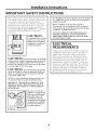 3
3
-
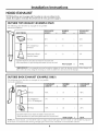 4
4
-
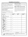 5
5
-
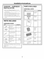 6
6
-
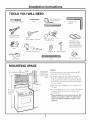 7
7
-
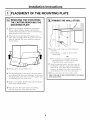 8
8
-
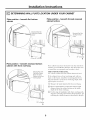 9
9
-
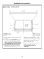 10
10
-
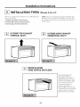 11
11
-
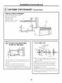 12
12
-
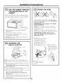 13
13
-
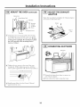 14
14
-
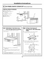 15
15
-
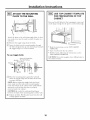 16
16
-
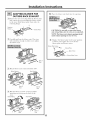 17
17
-
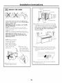 18
18
-
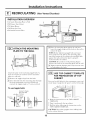 19
19
-
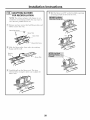 20
20
-
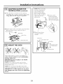 21
21
-
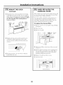 22
22
-
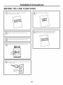 23
23
-
 24
24
-
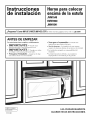 25
25
-
 26
26
-
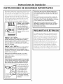 27
27
-
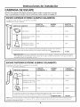 28
28
-
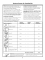 29
29
-
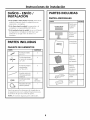 30
30
-
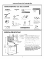 31
31
-
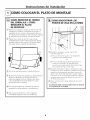 32
32
-
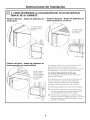 33
33
-
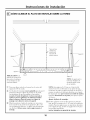 34
34
-
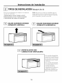 35
35
-
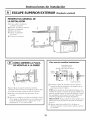 36
36
-
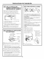 37
37
-
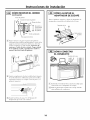 38
38
-
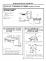 39
39
-
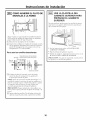 40
40
-
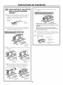 41
41
-
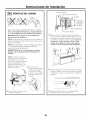 42
42
-
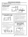 43
43
-
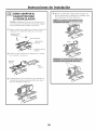 44
44
-
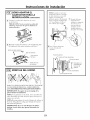 45
45
-
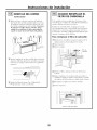 46
46
-
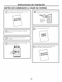 47
47
-
 48
48


GE HVM1540DM2WW Guía de instalación
- Categoría
- Microondas
- Tipo
- Guía de instalación
En otros idiomas
- English: GE HVM1540DM2WW Installation guide
Documentos relacionados
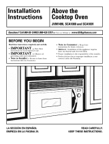
Otros documentos
-
Kenmore 79080379310 Guía de instalación
-
Frigidaire FPBM3077RFA Guía de instalación
-
-
-
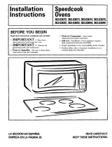 Kenmore Elite 36363694301 Guía de instalación
-
Frigidaire FMV152KQA Guía de instalación
-
Leviton S2000-S15 Instrucciones de operación
-
Leviton S2000-S15 Instrucciones de operación
