Kenmore Elite 36363694301 Guía de instalación
- Categoría
- Microondas
- Tipo
- Guía de instalación
Este manual también es adecuado para

Installation
Instructions
Speedcook
vens
363.63672,363.63673,363.63674,363.63679,
363.63692,363.63693,363.63694,363.63699
BEFORE YOU BEGIN
Read these instructions completely and carefully.
• IMPORTANT - Savethese
instructions for local inspector's use.
• IMPORTANT - Obse_eall
governing codes and ordinances.
• Note to Installer - Be sure to leave these
instructions with the Consumer.
• Note to Consumer - Keepthese
instructions for future reference.
• Skill level - Insta!ladon of dais appliance requires
basic mechanical and electrical skills.
• Proper installation is the responsibility of the installer.
• Product failure due to improper installation is not
covered under the Warranty.
LA SECCION EN ESPAI_iOL
EMPIEZA EN LA PAGINA 25.
READ CAREFULLY,
KEEP THESE INSTRUCTIONS.

Installation Instructions
CONTENTS
General information
Important Safety Instructions ................ 3
Electrical Requirements ..................... 3
Hood Exhaust .......................... 4, 5
Damage---Shipment/Installation .............. 6
Parts Included ............................ 6
Tools You W'dl Need ....................... 7
Mounting Space o 7
Step-by-step installation guide
Placement of Mounting Plate .............. 8-10
Removing the Mounting Plate . : ....... 8
Finding the Wall Studs ............... 8
Determining Wall Plate Location ....... 9
Aligning the Wall Plate .............. 10
Installation Types ..................... . 11-22
[] Recirculating ................... 12-14
Attach Mounting Plate to Wall ..... 12
Preparation of Top Cabinet ....... 13
Mount the Oven ............ 13, 14
Installing the Charcoal Filter ...... 14
[] Outside Back Exhaust ............ 15-18
Preparing Rear Wall for
Outside Back Exhaust ........... I5
Attach Mounting Plate to Wall..15, 16
Preparation of Top Cabinet ....... 16
Adapting Blower for Outside
Back Exhaust ............... 16, 17
Mount the Oven ............... 18
[] Outside Top Exhaust ............. 19-22
Attach Mounting Plate to Wall ..... 19
PrepaFation of'Fop Cabinet ....... 20
Adapting Blower for
Top Exhaust ................ 20, 21
Assemble and Install Adapter ..... 21
Mount the Oven ............ 21, 22
Adjust the Exhaust Adapter ....... 22
Connecting Ductwork ........... 22
Before You Use Your Oven .................. 23
Secei6n en _ol ..................... 25--47
2

Installation Instructions
IMPORTANT SAFETY INSTRUCTIONS
This product requires a thre_prong grounded oudet.
The installer must pecfonn a gTound continuity check on
the power outlet box before beginning the installation to
instu'e that the outlet box is properly grounded, ff not
properly grounded, or if the outlet box does not meet
electrical requirements noted (under ELECIa_CAL
REQUIREMENTS), a qualified electrician should be
employed to correct any deficiencies.
I CAUTION:
For personal safety, remove
house fuse or open circuit
breaker before beginning
installation to avoid severe
or fatal shock injury.
CAU1]ON: Ferpo on themou g
surface must be capable of supporting the cabinet load, in-
adch'fion to the added weight of this 63-85 pound product,
plus additional oven loads of up to 50 potmds or atotal
weight of 113-135 potmds.
CAUTION: For personal safety, this product
cannot be installed in cabinet arrangeme_ats such as an
island or a peninsula. It must be mounted to BOTH
a top cabinet AND a walL
NOTE: For easier installation madpersonal safety, it is
recommended that two people install this product.
IMPORTANT--_ READ CAREFULLY. FOR
PERSONAL SAFETY, THIS APPIJANCE MUST BE
PROPERLY GROUNDED TO AVOID SEVERE OR
FATALSHOCK.
The power cord of this
appliance is equipped with
a _-ee-pro_g _o_mding)
l_ug which mates with
a standard three-prong
(groundhlg) wall x_eptade
to minimize the possibility
of dec_wicshock hazard
from this appliance.
You should have the wall receptacle and circuit checked
by a qualified elec_clan to make sure the receptacle is
properly grounded.
Where a standard two_reng wall receptade is
encountered, it is very important to have it replaced
with a properly grounded three-prong wall receptacle,
installed by a qualified electrician.
DO NOT, LrNDER ANY CIRCUMSTANCES, CUT,
DEFORM OR REMOVE ANY OF THE PRONGS
FROM THE POWER CORD. DO NOT USE WITH
AN EXTENSION CORD.
ELECTRICAL
REQUIREMENTS
Product rating is 120 volts AC, 60 Hertz, 15 amps and
1.70 kilowatts. This product must be connected to
a supply circuit of the proper voltage and frequency.
Ware size must conform to the requirements of the
National Electrical Code or the prevailing local code for
this kilowatt rating. The power supply cord and plug
should be brought to a separate 15 to 20 ampere branch
circuit single grounded outlet. The outlet box should be
located in the cabinet above the oven. The outlet box and
supply circuit should be installed by a qualified electrician
and conform to the National Electrical Code or the
prevailing local code.
3

Installation Instructions
HOOD EXHAUST
NOT_ Read these next two pages only if you plan to vent your exhaust to the outside.
If you plan to reclrculate the air back into the room, proceed to page 6.
OUTSIDE TOP EXHAUST (EXAMPLE ONLY)
The following chart desclibes an example of one possible ductwork installation.
EQUIVALENT NUMBER EQUIVALENT
DUCT PIECES LENGTH x USED = LENGTH
RoofCap 24 Ft. x (1) 24 Ft.
12Ft.StraightDuct 12 Ft. x (1) 12Ft.
(6"Round)
Rectangular-to-Round 5 Ft. x (1) 5 Ft.
TransitionAdapter*
Equivalentlengthsofductpiecesarebasedon actualtestsand
reflectrequirementsfor goodventingperformancewith anyventhood.
Total Length = 41 Ft.
*IMPORTANT: ff a rectangular-to-round transition adapter is used, the bottom comers of the damper will have
to be cut to fit, using the fin snips, in order to allow free movement of the damper.
OUTSIDE BACK EXHAUST (EXAMPLE ONLY)
The following chart describes an exmnple of one possible duc ,twork instanadon.
DUCT PIECES
EQUIVALENT NUMBER EQUIVALENT
LENGTH* x USED -- LENGTH
40 Ft. x (1) 40 Ft.
Wall Cap
3Ft.StraightDuct 3 Ft. x (1) = 3 Ft.
(3¼"x 10" Rectangular)
(_ 30° Elbow 10Ft. x (2} 20 Ft.
Equivalentlengthsof ductpiecesare basedon actualteatsand
reflectrequirementsforgoodventingperformancewith anyventhood.
Total Length = 63 Ft.
NOTE: For back exhaust, care should be taken to align exhaust with space between studs, or wall should be
prepared at the time it is constructed by leaving enough space between the wall studs to accommodate exhausL
4

Installation Instructions
NOTE: If you need to install ducts, note that the total duct
length of 3¼" x 10" rectangular or 6" diameter round duct
should not exceed 140 equivalent feet.
Outside ventilation requires a HOOD EXHAUST DUCT.
Read the following carefiflly.
NOTE: It is important that venting be installed ttsing
the most direct route and with as few elbows as possible.
This ensures clear venting of exhaust and helps prevent
blockages. Also, make sure dampers swing freely and
nothing is blocldng the ducts.
Exhaust connection:
The hood exhaust has been designed to mate with
a standard 3¼" x 10" rectangular ducL
ff a round duct is required, a rectangular-to-round
transition adapter must be used. Do not use less than
a 6"diameter duct.
Maximum duct length:
For satisfactory air movement, the total duct length of
".5¼"x 10" rectangular or 6" diameter round duct should not
exceed 140 equivalent feet.
Elbows, transitions, wall and roof caps, etc.,
present additional resistance to airflow and are equivalent to
a section of straight duct which is longer than their actual
physical size. When calculating the total duct length, add the
equivalent lengths of all tlansidons and adapters plus the
length of all straight duct sections.
The chart below shows you how to calculate total equivalent
ductwork length using the approximate feet of equivalent
length of some typical ducts.
;DUCT PIECES
G
g
RectangulaFto-Round
TransitionAdapter*
Wall Cap
90° Elbow
45° Elbow
90° Elbow
45° Elbow
EQUIVALENT NUMBER
LENGTH x USED
RoofCap
StraightDuct6" Roundor
3_A"x10" Rectangular
5R.
40Ft.
lOFt.
5R.
25 Ft.
5R.
24Ft.
1R.
x ( )
x ( )
x ( )
x ( )
x ( }
x ( )
x ( )
x ( )
EQUIVALENT
LENGTH
Ft.
Ft.
F_.
Ft.
Ft,
Ft,
Ft.
Total Ductwork = Ft.
* IMPORTANT: Ifa rectangularao-round transition adapter is used,
the bottom comers of the damper will have to he cut to fit, using
the tin snips, in order to allow free movement of the damper.
Equivalent lengths of duct pieces are based on actual tests and
reflect _luirements for good venting perfoimance with any
vent hood.
5

Installation Instructions
DAMAGE SHIPMENT/
INSTALLATION
• If the unit is damaged in shipment, retuna the unit to the
store in which it was bought for repair or replacement.
• If the unit is damaged by the customer, repair or
replacement is the responsibility of the customer.
• If the unit is damaged by the installer (if other than the
customer), repair or replacement must be made by
arrangement between customer and installer.
PARTS INCLUDED
HARDWARE PACKET
PART QUANTITY
WoodScrews 2
_' 1¼0x2"1
, ToggleBolts(and 4
_ wing nuts)(¼"x 3")
Self-aligningMachine 3
Screws(¼"-28x3¼")
NylonGrommet 2
(formetalcabinets)
Metal Screws 1 black
(_,_"x ½") 2 bronze
PowerCordStrap 1
(plastic)
You will find the installation hardware contained in a
)acket with the unitCheck to make sure you have all
these parts.
NOTE: Some extra parts are included.
PARTS INCLUDED
ADDITIONAL PARTS
PART QUANTITY
1
TOp CABINJ_i"TEIdPLIffI_
I_Sl"ALLAT'_
J
i
TopCabinet
Template
RearWall
Template
Installation
Instructions
Separately 2
Packed
Grease
Filters
Exhaust 1
Adapter
Damper 1
Charcoal 1
Filter
6

Installation Instructions
TOOLS YOU WILL NEED
# 1and#2 Phillipsscrewdriver Pencil
]in snips(forcutting
damper,if required)
G]oves
Safetygoggles
Scissors
(tocuttemplate,if necessary)
Saw(saber,holeorkeyhole)
Rulerortapemeasure
eightedge
Electricdrill with 3Ag'._6".
Vz"and_" drill bits
Studfinder or
Hammer(optional)
Level
Carpentersquare
(optional)
Fillerblocksor scrap
woodpieces,if needed
fortopcabinetspacing
(usedonrecessedbottom
cabinetinstallationsonly)
Ductandmaskingtape
MOUNTING SPACE
66"ormore
fromthe floor
tothetopof
theoven
Bottomedgeof
cabinetneedsto
be30"ormore
the cooking
surface
NOTES:
• The space between the cabinets must be 30" wide
and free of obstructions.
• If the space between the cabinets is greater than
30;'a Filler Panel Kit may be used to fill in the
gap between the oven and the cabinets. Your
Use & Care Guide contains the kit number for
your model.
• This oven is for installation over ranges up to
36" wide.
• If you are going to vent your oven to the outside,
see Hood Exhaust Section for exhaust duct
preparation.
• When installing the oven beneath smooth, flat
cabinets, be careful to follow the inswuctions on
the top cabinet template for power cord clearance.
7

Installation Instructions
PLACEMENT OF THE MOUNTING PLATE
I-_ REMOVING THE OVEN FROM
THE CARTON/REMOVING THE
MOUNTING PLATE
[] Remove the box containing the installation
instructions, filters, exhaust adapter, damper
and the small hardware bag. Do not remove
the Styrofoam protecting the front of the oven.
[] Fold back all 4 carton flaps fully against carton
sides. Then carefully roll the oven and carton over
onto the top side. The oven should be resting in
the Styrofoam.
[] Pull the carton up and off the oven.
[_The mounting plate is attached to the back of the
oven. Remove the two screws holding it to the oven.
The plate will be used as the rear wall template and
for mounting the oven to the wall.
i
[_Set the oven upright. Remove and properly discard
plastic bags and Styrofoam.
[] Open the oven door and remove the styrofoam
pack from inside the oven. Remove the tape
covering the turntable hub.
[] FINDING THE WALL STUDS
ii wail i i
Center_i if!
[] Find the studs, using one of the following
methods:
A. Stud finder - a magaaetic device which
locates nails.
OR
B. Use a hammer to tap lighdy across the
mounting surface to find a solid sound.
This will indicate a stud location.
[] After locating the stud(s), find the center by
probing the wall with a small nail to find file
edges of the stud. Then place a mark halfway
between the edges. The center of any adjacent
studs should be 16" or 24" from this mark.
]Draw a line down the center of the studs.
THE OVEN MUST BE CONNECTED TO AT LEAST
ONE WALL STUD.
8

Installation Instructions
[-_ DETERMINING WALL PLATE LOCATION UNDER YOUR CABINET
Plate position - beneath flat bottom
cabinet
Plate position - beneath framed recessed
cabinet bottom
MountingPlateTabs
the CabinetBottom
L
At least30", upto36"
MountingPlateTabs
TouchingtheBack
Frame
L
II
30"toCooktop
t
Plate position - beneath recessed bottom
cabinet with front overhang
MountingPlatewith
TabsBelowCabinet
Bottomthe Same
Distanceas the Front
gDepth
L
I II
30"toC9oktop
f
Your cabinets may have decorative uam that interferes
with the oven installation. Remove the decorative trim
to install the oven properly and to make it level.
THE OVEN MUST BE LEVEL.
Use a level to make sure the cabinet bottom is level.
If the cabinets have a front overhang only, with no
back or side frame, install the mounting plate down
the same distance as the front overhang depth. This
will keep the oven level.
[] Measure the inside depth of the front overhang.
[] Draw a horizontal line on the back wall an equal
distance below the cabinet bottom as the inside
depth of the front overhang.
[] For this type ofinstallauon with front overhang only,
align the mounting tabs with this horizontal line, not
touching the cabinet bottom as described in Step D,
9

Installation Instructions
ALIGNING THE WALL PLATE
HoleC
DrawaVertical
LineonWall
•,,e--frorn Centerof
TopCabinet
o o o
0 0 0 0 0 0 0 .b 0 0 0 0 O 0 0 0 0 0
0 0 0 O O OIO O O O O 0 0
I
CAUTION: Wear gloves
to avoid cutting fingers on
sharp edges.
_f I
AreaE
HoleD
[] Draw a vertical line on the wall at the center of the
30" wide space.
[_Use the mounting plate as the template for the rear
wall. Place the mounting plate on the wall, making
sure that the tabs are touching the bottom of the
cab'met or the level line drawn in Step C for cab'mets
with front overhang. Line up the notch and center line
on the mounting plate to the center line on the wall.
[] While holding the mounting plate with one hand,
draw circles on the wall at holes A, B, C and D (see
illustration above/actual plate marked with arrows).
Four holes must be used for mounting.
[]
NOTE: Holes C and D are inside area E, ff neither
C nor D is in a stud, find a stud somewhere in area E
and draw a fifth circle to line up with the stud. It is
important to use at least one wood sca'ewmounted
firmly in a stud to support the weight of the oven.
Set the mounting plat e aside.
Drill holes on the circles, ff there is a stud, drill a _i6"
hole for wood screws. For holes that don't line up with
a stud, drill a _" hole for toggle bolts.
NOTE: DO NOT MOUNT THE PLATE AT THIS TIME.
10

Installation Instructions
INSTALLATION TYPES (Choose A, B or C)
This oven is designed for adaptation to file following
3 types of ventilation:
A. Redrodating (Non-Vented Ductless)
B. Outside Back Exhaust (Horizontal Duct)
C. Oue_ide Top Exhaust (Vertical Duct)
NOTE: This oven is shipped assembled for Recirculating
Exhaust. Select the type of ventilation required for your
installation and proceed to that section.
_-_ RECIRCULATING
(NON-VENTED DUCTLESS)
OUTSIDE BACK EXHAUST
(HORIZONTAL DUCT)
NOTE: A disposable charcoal
filter is included with the oven
and needs to be installed for
the non-vented exhaust to
help remove smoke and odors. _ OUTSIDE TOP EXHAUST
(VERTICAL DUCT)
AdapterinPlacefor
, Exhaust
11

Installation Instructions
RECIRCULATING (Non-Vented Ductless)
INSTALLATION OVERVIEW
A1. Attach Mounting Plate to Wall
A2. Prepare Top Cabinet
A3. Mount Oven
A4. Install Charcoal Filter
NOTE: The exhaust adapter
with damper is not needed for
reeirculating models. You may
want to save it for possible
future use.
./
//
I-_ ATTACH THE MOUNTING
PLATE TO THE WALL
Attach the plate to the wall using toggle bolts.
At least one wood screw must be used to attach the
plate to a wall stud.
[] Remove the toggle wings from the bolts.
[2] Insert the bolts into the mounting plate through
the holes designated to go into drywall and
reattach the toggle wings to _" onto each bolt.
To use toggle bolts:
Spacingfor Toggles
MoreThanWall
-J_._---Thickness
Mounting
Plate
Bolt End
[_] Place the the wall andmounting plate against
insert the toggle wings into the holes in the wall
to mount the plate.
NOTE: Before tightening toggle bolts and wood
screw, make sure the tabs on the mounting plate
touch the bottom of tile cabinet when pushed
flush against the wall and that the plate is properly
centered under the cabinet.
CAUTION: Be careful to avoid pinching fingers
between the back of the mounting plate and the wall.
[] Tighten all bolts. Pull the plate away from the wall
to help tighten the bolts.
12

Installation Instructions
[_ USE TOP CABINET TEMPLATE
FOR PREPARATION OF TOP
CABINET
You need to drill holes for the top support screws, and
a hole large enough for the power cord to fit through.
• Read the instructions on the TOP CABINET
TEMPLATE.
" Tape it underneath the top cabinet.
• Drill the holes, following the instructions on the
TOP CABINET TEMPLATE.
CAUTION: Wear safety goggles when drilling holes
in the cabinet bottom.
I-_ MOUNT THE OVEN
FOR EASIER INSTALLATION AND PERSONAL
SAFETY, WE RECOMMEND THAT TWO PEOPLE
INSTALL TillS OVEN.
IMPORTANT: Do not grip or use handle
during installation.
NOTE: If your cabinet is metal, use the nylon
grommet around the power cord hole to prevent
cutting of the cord.
NOTE: We recommend using filler blocks if the
cabinet front hangs below the cabinet bottom shelf.
IMPORTANT: If f'dler blocks are not
used, case damage may occur from over
tightening screws.
NOTE: When moundng
the oven, thread power cord
through hole in bottom of
top cabinet. Keep it tight
throughout Steps 1-3. Do
not pinch cord or lift oven [_Lift oven, tilt it
by forward and hook
slots at back bottom
edge onto two lower
tabs of mounting
[_]Rotate front of oven up
against cabinet bottom.
[3]Insert a self-aligning screw through top center
cabinet hole. Temporarily secure the oven by turning
the screw at least two full turns after the threads
have engaged. (It will be completely tightened later.)
Be sure to keep power cord fight. Be careful not to
pinch the cord, especialIy when mounting flush to
bottom of cabinet.
13

Installation Instructions
[_-_] MOUNT THE OVEN
(continued)
CabinetFront
CabinetBottomShelf
Equivalentto
Depth
efCabinet
Recess
Self-AligningScrew
OvenTop
[_ Attach the oven to the top cabinet.
[] Insert 2 self-aligning screws
through outer top cabinet
holes. Turn two filll turns on
each screw.
[_] Tighten center
screw completely.
[] Tighten the outer two screws to the top of the
oven. (While tightening screws, hold the oven in
place against the wall and the top cabinet.)
[_Install grease filters. See the Use & Care Guide
packed with the oven.
INSTALLING THE
CHARCOAL FILTER
[] Remove 2 screws on top of grille using a
Phillips screwdriver.
[] Open die doon
[] Remove the grille.
[_ Insert the filter into the
oven as
shown,
maneuvering it behind the plastic grille undl it fits
squarely into place. It will rest at an angle behind
the plasdc grille on two side support tabs and in
front of the right rear tab. When properly
installed, the wire mesh of the filter should be
visible from the front.
/
[] Replace the grille and the 2 screws.
[] Close the door.
IIIL -Zl
Insertmesh-sidedown
14

Installation Instructions
OUTSIDE BACK EXHAUST (Horizontal Duct)
INSTALLATION OVERVIEW
B1. Prepare Rear Wall
B2. Attach Mounting Plate to Wall
B3. Prepare Top Cabinet
B4. Adjust Blower
B5. Mount Oven
1
I-_ PREPARING THE REAR WALL
FOR OUTSIDE BACK EXHAUST
You need to cut an opening in the rear wall for
outside exhaust.
• Read the instructions on the REAR WALL
TEMPLATE.
• Tape it to the rear wall, lining up with the holes
previously drilled for holes A and B in the wall
plate.
• Cut the opening, following the instructions of the
REAR WALL TEMPLATE.
I-_ ATTACH THE MOUNTING
PLATE TO THE WALL
Attach the plate to the wall using toggle bolts. At least
one wood screw must be used to attach the plate to
a wall stud.
[] Remove the toggle wings from the bolts.
[] Insert the bolts into the mounting plate through
the holes designated to go into drywall and reattach
the toggle wings to _" onto each bolt.
15

Installation Instructions
To use toggle bolts:
Mounting
Plate
Spacingfor TogglesMore
ThanWall
Thickness
ToggleWings
all
BoltEnd
[] Place the mounting plate against file wall and
insert the toggle wings into the holes in the wall
to mount the plate.
NOTE: Before tightening toggle bolts and wood
screw, make sure the tabs on the mounting plate
touch the bottom of the cabinet when pushed flush
against the wall and that the plate is properly
centered under the cabinet.
CAUTION: Be careful to avoid pinching fingers
between the back of the mounting plate and the wall.
[] Tighten all bolts. Pull the plate away from the wall
to help tighten the bolts.
_-] USE TOP CABINET TEMPLATE
FOR PREPARATION OF TOP
CABINET
You need to drill holes for the top support screws and
a hole large enough for the power cord to fit through.
• Read the instructions on the TOP CABINET
TEMPLATE.
• Tape it underneath the top cabinet.
• Drill the holes, following the instructions on the
TOP CABINET TEMPLATE.
CAUTION: Wear safety goggles when drilling holes
in the cabinet bottom.
[_ ADAPTING BLOWER FOR
OUTSIDE BACK EXHAUST
[_ Remove the three screws that hold the blower plate
to dae oven. Slide blower plate from under its
retaining flange. Remove and save the screw that
holds blower motor to oven.
_V
FRetn_gnei'___ "_r'_- BlowerPlate
[] Carefully pull out the blower unit. The wires
will extend far enough to allow you to adjust
the blower unit.
EndA
[] Roll the blower unit so the fan blade openings
are facing up.
BeforeRolling After Rolling
[4] Rotate blower unit counterclockwise 180 °.
BeforeRotation
After Rotation
3ackof
Oven
16

Installation Instructions
I_ Gently remove the wires from the
grooves.
Reroute the wires through grooves on other side
of the blower unit.
BeforeRerouting After Beroudng
WiresRoutedThroughRightSide WiresRoutedThroughleft Side
[_ Roll the blower unit 90 ° so that fan blade openings
are facing out tile back of the oven.
BeforeRolling
Oven Oven
[] Place the blower unit back into the opening.
EndA
CAUTION: Do not pull or stretch the blower unit
wiring. Make sure the wires are not pinched.
NOTE: The blower unit exhaust openings should
match exhaust openings on rein"of ovep_
_] Replace the blower in theplate posidon
same
as before with the screws.
,€. B'°B,eorwPLTws
BeokofOven
[_ Insert the tabs on each side of the damper into
file holes at the inside rear of the adapter.
_-_ Exhaust
Adapter
[_ Attach the exhaust adapter to the rear of the
oven by sliding it into the guides at the top center
of the back of tile oven.
ExhaustAdapter .,_
Slideexhaust _
adapterinto
guideson
oven rear. I._
_ Damper
(hingesideup)
_V "_'_r_ Screws
Tabs
, Guides
Push in securely until it is in the lower locking
tabs. Take care to assure the damper hinge is
installed so that it is at the top and that the
damper swings freely.
[_ Secure the exhaust adapter to the oven with the
two bronze metal screws provided.
17

Installation Instructions
MOUNT THE OVEN
FOR EASIER INSTALLATION AND PERSONAL
SAFETY, WE RECOMMEND THAT TWO PEOPLE
INSTALL THIS OVEN.
IMPORTANT: Do not grip or use handle
during installation.
NOTE: If your cabinet is metal, use tile nylon
grommet around the power cord hole to prevent
cutting of the cord.
NOTE: We recommend using filler blocks if the
cabinet front hangs below the cabinet bottom shelf.
IMPORTANT: If filler blocks are not
used, case damage may occur from over
tightening screws.
NOTE: When mounting
the oven, thread power
cord through hole in
bottom of top cabinet.
Keep it tight throughout
Steps 1-3. Do not pinch
cord or lift oven by
p_flling cord.
l[_Lift oven, tilt it
forward and hook slots
at back bottom edge
onto two lower tabs
of mounting plate.
2]Rotate front of oven up
against cabinet bottom.
[_]Insert a serf-aligning screw through top center cabinet
hole. Temporarily secure the oven by turning the
screw at least two full turns after the threads have
engaged. (It will be completely tightened later.) Be
sure to keep power cord fight. Be careful not to pinch
the cord, espedally when mourning flush to bottom
of cabinet.
CabinetFront
CabinetBottomShelf
FillerBlock
I quivalent
to Depth
ofCabinet
Recess
Self-AligningScrew
OvenTop
[_]Attachthe oven to the top cabinet.
[] Insert 2 self-aligning screws
through outer top cabinet
holes. Turn two full turns on
each screw.
I
]Tighten center
screw completely.
[] Tighten the outer two screws to the top of the
oven. (While tightening screws, hold the oven
in place against the wall and the top cabinet.)
[_]Install grease filters. See the Use & Care Guide
packed with the oven.
18

Installation Instructions
OUTSIDE TOP EXHAUST (Vertical Duct)
INSTALLATION OVERVIEW
C1. Attach Mounting Plate to Wall
C2. Prepare Top Cabinet
C3. Adjust Blower
CA. Install Adapter
C5. Mount Oven
C6. Adjust Exhaust Adapter
C7. Connect Ductwork
1
I-_ ATTACH THE MOUNTING
PLATE TO THE WALL
Attach the plate to the wall using toggle bolts. At
least one wood screw must be used to attach the
plate to a wall stud.
[] Remove the toggle wings from the bolts.
[] g
Insert the bolts into the mounting plate throu h
the holes designated to go into drywall and
reattach the toggle wings to Y_"onto each bolt.
To use toggle bolts:
Mounting
Plate.
SpacingforToggles
Mare ThanWall
-_.,--_Thickness
[eWings
BoltEnd
[] Place the mounting plate against the wall and
insert the toggle wings into the holes in the wall
to mount the plate.
NOTE: Before tightening toggle bolts and wood
screw, make sure the tabs on the mounting plate
touch the bottom of the cabinet when pushed flush
against the wall and that the plate is properly
centered under the cabinet.
CAUTION: Be careful to avoid pinching fingers
between the back of the mounting plate and the wall.
[_] Tighten all bolts. Pull the plate away from the wall
to help tighten the bolts.
19

Installation Instructions
USE TOP CABINET TEMPLATE
FOR PREPARATION OF TOP
CABINET
You need to drill holes for the top support screws,
a hole large enough for the power cord to fit through
and a cutout large enough for the exhaust adapter.
• Read the instrucdons on the TOP CABINET
TEMPLATE.
• Tape it underneath the top cabinet.
• Drill the holes, following the instructions on the
TOP CABINET TEMPLATE.
CAUTION: Wear safety goggles when drilling holes
in the cabinet bottom.
[_ ADAPTING BLOWER
FOR TOP EXHAUST
_J] Remove and save screws that hold blower plat e to
the oven.
,_ _ -'<-- BlowerPlateScrews
tl
._- BackofOven
_] Slide the blower plate from under its
retaining
flange and lift it off. Remove and save screw that
holds the blower motor to oven.
Retaining
"_ BlowerPlate
Screw
[] Carefully. pull out the blower unit. The wires
will extend far enough to allow you to adjust the
blower trait.
[] Roll the blower unit 90 ° so that fan blade openings
are facing up.
R011
NOTE: Make sure wires remain routed in the
grooves of the motor frame.
20

Installation Instructions
ADAPTING BLOWER FOR
TOP EXHAUST (continued}
[_] Place the blower unit ]_ack into the opening.
CAUTION: Do not pull or stretch the blower unit
wiring. Make sure the wires are not pinched.
[_ Secure blower unit to oven with the removed
screw
in Step 2. Insert the screw in bottom right screw
hole on the back of the oven.
Re lace
[] p
Step 1.
blower plate with the screws removed in
= _*"_ BlowerPlateScrews
•=r-...BlowerMotor
Screw
ASSEMBLE AND INSTALL
ADAPTER
_ -.,,t--_ Damper
t J
__ Adapter
_ BlowerPlate
0vee
[_Place the oven in its upright position_ with the top
of the unit facing up.
[_ Insert the tabs on each side of the damper into the
holes at the inside rear of the adapter.
[3"] Attach the exhaust adapter to the blower plate with
the two bronze metal screws provided.
Make sure that the damper pivots easily before
mounting oven.
You will need to make adjustments to assure proper
alignment with your house exhaust duct after the
oven is installed.
I-_ MOUNT THE OVEN
FOR EASIER INSTALLATION AND PERSONAL
SAFETY,,WE RECOMMEND THAT TWO PEOPLE
INSTALL THIS OVEN.
IMPORTANT: Do not grip or use handle
during installation.
NOTE: If your cabinet is metal, use the nylon
grommet around the power cord hole to prevent
cutting of the cord.
NOTE: We recommend using filler blocks if the
cabinet front hangs below the cabinet bottom shelf.
IMPORTANT: If filler blocks are not ttsed,
case damage may occur from over tightening
screws.
NOTE: When mounting
the oven, thread power
cord through hole in
bottom of top cabinet.
Keep it tight throughout
Steps 1-3. Do not pinch
cord or lift oven by
pulling cord.
[-_Lift oven, tilt it forwar_
and hook slots at back
bottom edge onto
two lower tabs of
mounting plate.
21

Installation Instructions
MOUNT THE OVEN
(continued)
[_] Insert a seK-'aligning screw tbrougta top center cabinet
hole. Temporarily secure the oven by turning the
screw at least two full turns after the threads have
engaged. (It will be completely tightened later.) Be
sure to keep power cord fight. Be careful not to pinch
the cord, espedally when mounting flush to bottom
of cabinet.
CabinetFront
r__.._Cebinet BottomShelf
I',I,M_ FillerBlock
___._ofCabinetRecess
OvenTop
[4]Attach the oven to the top cabinet.
[] insert 2 self-aligning screws through
outer top cabinet holes. Turn two full
turns on each screw.
_] Tighten center
screw completely.
[_]Tighten the outer two screws to the top of the
oven. (While tightening screws, hold the oven
in place against the wall and the top cabinet.)
[_]Install grease filters. See the Use & Care Guide
packed with the oven.
ADJUST THE EXHAUST
ADAPTER
Open tile top cabinet and adjust tile exhaust adapter
to connect to the house duct.
Damper
BackofOven
/
CONNECTING DUCTWORK
HouseDuct
[_] Extend the house duct down to connect to the
exhaust adapter.
[] Seal exhaust duct joints using duct tape.
22

Installation Instructions
BEFORE YOU USE YOUR OVEN
I
]
[] Make sure the oven has been installed
according to instructions.
[--_] Remove all packing material from the oven.
[_] Install turntable and wheeled ring in cavity.
[--_] Replace house flxse or turn breaker back on.
I
[_ Read the Use & Care Guide.
[ff_] KEEP INSTALLATION INSTRUCTIONS
FOR THE LOCAL INSPECTOR'S USE.
[_] Plug power cord into a dedicated 15 to 20 amp
electrical outlet.
Insureproper
groundexists
beforeuse I
23

24

Instrucciones
de instalacion
Hornos de
Speedcook
363.63672,363.63673,363.63674,363.63679,
363.63692,363.63693,363.63694,363.63699
ANTES DE EMPEZAR
Lea estas insU-ucciones completa y cuidadosamente.
• IMPORTANTE - O_rdees_
instrucciones para el uso del inspector local.
• IMPORTANTE - Cump]acon
todos los c6digos y ordenanzas gubernamentales.
• Nota para el instalador - Asegfirese de dejar
estas instrucciones con el consumidor.
• Nota para el consumidor - Guarde estas
instrucciones para futut-a referencia.
• Nivel de destrezas - La instalaci6n de este aparato
requiere de destrezas b_sicas de mecfinica y electricidad.
• La instalaci6n apropiada es responsabilidad
del instalador.
• La falla del producto debido a una instalaci6n
inapropiada no est_ cubierta por la garantia.
LEA CUIDADOSAMENTE.
GUARDE ESTAS INSTRUCCIONES.
25

Instrucciones de instalacion
CONTENIDO
Informacibn general
Instrucclones de seguridad importantes ....... 27
Requisltos el_ctrlcos ..... 27t °°o. °oo° °°° i .°_° °
Campana de escape .................... 28, 29
Dafios- Envio / Instalaci6n ................. 30
Partes incluidas ......... 30
°.o.* oo*°*°°*o° * *
Herramientas que necesitarfi ................ 31
Espacio de montaje ....................... 31
Guia de instalacibn paso por paso
C6mo colocar el plato de montaje ......... 32-34
C6mo remover el plato de montaje .... 32
C6mo encontrar madera s61ida
en la pared ....................... 32
C6mo detenninar la localizaci6n de
las placas de la pared ................ 33
C6mo alinear la placa de la pared ..... 34
Tipos de instalaci6n .................... 35-46
[] Reciroalad6n ................... 36-38
C6mo adherir el plato de
montaje a la pared .............. 36
Prepavaci6n del gabinete
superior ...................... 37
C6mo montar el homo ....... 37, 38
C6mo instalar el filtro de
carbonilla ............ 38
°**0* ****
[] Escape posterior exterior .......... 39-42
C6mo preparar la pared posterior
para el escape posterior exterior ...39
C6mo adherir el plato de
montaje a la pared ........... 39, 40
C6mo preparar el gabinete
superior ...................... 40
C6mo adaptar el calefactor para
el escape exterior posterior ... A0, 41
C6mo montar el homo .......... 42
[] Escape superior exterior ........... 43-46
C6mo adherir el plato de
montaje a la pared .............. 43
C6mo preparar el gabinete
superior ...................... 44
C6mo adaptar el calefactor para
escape superior exterior ....... 44, 45
C6mo ensmnblar e instalar
el adaptador ................... 45
C6mo montar el homo ....... 45, 46
C6mo ajustar el adaptador
de escape .................... . 46
C6mo conectar el conducto ...... 46
Antes de eomenzar a usar su homo ........... 47
26

Instrucciones de instalacibn
INSTRUCCIONES DE SEGURIDAD IMPORTANTES
Este producto requiere un tomacorfiente el_cu'ico de tres
pat_s conectado a tien'a. El instalador debe lleval: a cabo
tma inspecci6n de continuidad a tierra en la caja el6cuica
antes de comenzar la instalaci6n para asegmxr que la
caja tomaconiente estfi conectada a tien'a de manez-a
apropiada. Si no lo es_, o si el tomaconiente no cumple
con los requisitos el_cu-icos indicados (bajo la secci6n
REQUISITOS ELECTRICOS), se debex_i recurrir a un
tficnico calificado para corregir cualqoier deficiencia.
p
PRECAUCION:
para seguridad personal,
remueva el fusible de la essa o
abra el intermptor de cirenito
antes de comenzar la instalaci6n
paza evitar descargas el6ctricas
sevetas o fatales.
p
PRECAUCION: posdehsegu daa
personal, la superficie de montaje debe set capaz de
soportar la carga del gabinete, ademfiS del peso adicional
(de 63 a 85 libras) de este producto, m,6s las cargas
adiclonales del homo de hasta 50 fibras o un peso total
entre 113 y 135 fibras.
PRECAUCION: Enposde seg daa
personal, este producto no puede set instalado en
slstemas de gabhaetes tales como los Uamados "islas" o
"peninsulas". _te debe set montado tanto a tm gabinete
superior como a una pared.
NOTA: Para una instalaci6tt mrs f_tcily eu pos de la
segmidad personal, se recomienda que dos personas
instalen este producto.
IMPORTANTF_ POR FAVOR, LEA
CUIDADOSAMENTE. EN POS DE LA SEGURIDAD
PERSONAL, ESTE APARATO DEBE SER CONECTADO
A TIERRA APROPIADAMENTE PARA EVITAR
DESCARGAS SEVERAS O FATAH_.
Aseg0rese/
doe ue. 21s2 e
tierraapropiada
antesdeluso
El cable el_a'ico de este
aparato estb equipado con
un enchufe de ires patas
(con conexi6n a fierra),
lo cual requiere que el
mo encaje con un
tomacorriente para Ires
patas (con conexi6n a tierra)
dep ed paramham
la peslbilidad de descar_
el_U'icas.
Deberfi hacer que un t6mico calificado inspeccione el
tomacorriente de pared y el drcuito para asegurarse de
que el tomacorriente est_ conectado a fierra de manera
aproFfiad_
Donde usted enenenU'e un tomacorriente est_dar de
dos patas, es muy importame que haga que el mismo se
cambie por uno de tres patas apropiadamente conectado
a tierra, hxstalado por un electridsta calificado.
BAJO NINGUNA CIRCUNSTANCIA NO CORTE,
DEFORME, O REMUEVA NINGUNA DE I.AS PATAS
DEL CABLE ELI_CTRICO. NO LO USE CON UNA
EXTENSIONELECTRICA.
REQUlSITOS ELECTRICOS
La clasificaci6n del producto es de 120 ratios CA (AC),
60 hertz, 15 anlpefios, y 1.70 kilovatios. Este producto
debe estm- conectado a un circuito de suministro del
voltaje y frecuencia apropiados. El tamafio del alambre
debe confom_arse a los requisitos del National Electric
Code o al c6digo local en efecto para este indice de
kilovatios. El cable el_ctrico de alimentaci6n yel
intermptor deberfin llevarse a un tomacorriente finico
conectado a fierra de 15 a 20 amperios. La caja del
tomacorfiente debea4testar localizada en el gabinete
encima del homo. La caja del tomacorriente debe ser
instalada por un electricista calificado ydebe conformarse
al National Electrical Code o al c6digo local en efecto.
27

Instrucciones de instalacibn
CAMPANA DE ESCAPE
NOTA: Lea las _guientes dos p_ginas solamente si planea ventilar el escape hacia el exterior.
Si por el contrario plauea recircular el aire de vuelta hada el sal6n, continue en la pfigina 30.
ESCAPE SUPERIOR EXTERNO (EJEMPLO SOLAMENTE)
La sigaliente labia describe un ejemplo de una posible instalaci6n de red de conductos.
PARTES DEL CONDUCTO
Tapadel techo
Conductorectode 12pies
(redondode6")
Adaptadordetransici6a
de rect_nguIoa redondo*
LONGITUD NOMERO
EQUlVALENTE x USADO
24 pies x (1)
12pies x (1)
5 pies x (1)
La Iongitudde [aspartesdelosconductosequivalentesest_basadaenpruebasrealesy
requisitosparaIograrunabuenaventilaci6nconcualquiercampanadeescape.
reflejanlos
LONGITUD
EQUIVALENTE
24 pies
12pies
5 pies
Longitud total = 41 pies
*IMPORTANTE: Si se usa un adaptador de transici6n de rect_ngulo a redondo, las esquinas del fondo del regulador de tiros
deber_n cortarse pala que encajen, ttsando las tijeras de cone, para pennidr et movimiento libre del regulador de tiros.
ESCAPE POSTERIOR EXTERNO (EJEMPLO SOLAMENTE)
La siguiente labia describe un ejemplo de una posible instalaci6n de red de conductos.
PARTES DEL CONDUCTO
Tapade pared
Conductorectode3 pies
(rectangularde 3¼" x 10")
LONGITUD NUMERO
EQUIVALENTE x USADO
40 pies x (1)
3 pies (1)X
Codode90° 10pies x (2)
La Iongitudde laspartesdelosconductesequivalentesest_basadaenpruebasrealesyreflejantos
requisitosparaIograrunabuenaventilaciOnconcualquiercampanade escape.
Longitud total =
LONGrrUD
= EQUIVALIENTE
40 pies
3 pies
20pies
63 pies
NOT-&=Para el escape posterior, se debe tener cuidado al alinear el escape entre los espacios de los postes de riga de la pared,
o la pared deben'a ser prepamda en el momento de su construcci6n dejando suficiente espacio entre los post_ de riga de la
pared para acomodar el escape.
28

Instrucciones de instalacibn
NOTA: Si usted necesita instalar conductos, tenga pendiente
que la longimd total del conducto rectangular de 3¼" x 10"
o el conducto redondo de 6" de di_rne_o no debe sobrepasar
140 pies equivalentes.
La venfilaci6n extema requiere utl CONDUCTO DE
CAMPANA DE ESCAPE. Lea lo sigaliente cuidadosamente.
NOTA: Es importante que la ventilaci6n sea instalada usando
la ruta mil direeta y con la menor canddad de codos posible.
Esto asegura la vendlaci6n del escape y ayuda a prevenir
bloqueo_. Tambi6n, cerd6rese de que el regulador de dro
pende libremente y nada bloquea los eonductos.
Conexiones de escape:
La campana de escape ha sido disefiada para encajar con
un conducto rectarlgular de 3¼" x 10" est,_ndar.
Si un conducto redondo es necesarlo, se debe usar tul
adaptador de transici6n de rectangular a redondo.
No use un conducto menor de 6° de difimetzo.
Longitud mdxima del conducto:
Para lograr tm movimiento safisfactorio del aire, la longimd
total del conducto rectangadar de 3¼" x 10" o e! conducto
redondo de 6" de di_imetro no debe sobrepasar 140 pies
equivalentes.
Los codos, transiciones, paredes y tapas de techo, etc.,
presentma resistencia adicional al flujo de aire y son equivalentes
a una secci6n de conducto recto el cual es m _ largo que su
tamafio fisico real. Cuando calcule la longitud total de]
conducto, agregue las tongitlldes equivalentes de todas las
tlmlsieiones y adaptadores, m_s la Iongitud de todas las
secciones de conducto rectas. La tabla mils adelante muestra
c6mo puede calcular la longitud aproximada de la red de
conductos usando pies aproximados de longitudes equivalentes
de algunes conductos dpieos.
PARTES DE CONDUCTO
i
g
Adaptadordetransici6nde
rect_nguloaredondo*
Tapade pared
Codode90°
Codode 45°
Codode90°
Codode 45°
Tapade techo
Conducterectode6" redondo
o rectangularde31A"x 10"
LONGITUD
EQUIVALENTE x
5 pies x
40pies x
10pies x
5 pies x
25pies
5 pies
24pies
I pies
NUMERO
USADO
( )
( )
( )
( )
x ( )
x ( )
x ( )
x ( )
Total red de conductos =
LONGITUD
= EQUIVALENTE
pies
pies
pies
pies
pies
pies
pies
pies
pies
* IM]PORTA.N'rE: Si se usa un adaptador de transici6n de rect_ngulo
a redonde, las esquinas del rondo del regulador de tiros deberka ser
cortadas pa[a que encffjen, usando las tijeras de cort£, para permitir
el movimiento libre del regulador de tiros.
La Iongitud de las partes de conductos equiwalentes est_ basada
en pruebos reales y reflejaJalos requisitos para Iograr una buena
venfilaci6n con cualquier campana de escape.
29

Instrucciones de instalacibn
DAI IOS - ENViO /
INSTALACION
• Si la tmidad se dafia durante el envlo, de'alelva la unidad
al ahnacdn donde la adquiri6 para su reparaci6n o
reemplazo.
• Si el diente dafia la unidad, la reparaci6n o e! reemplazo
es responsabilidad del cfiente.
• Si el instalador dal_a la unidad (si no es el cliente),
la reparaci6n o reemplazo se debe hacer por meclio
de un an-eglo entre el cliente y el instalador.
PARTES INCLUIDAS
PAQUETE DE ELEMENTOS
PARTE CANTIDAD
Torniltosdemadera 2
t_ _ (¼"x2")
Tornillosbasculantes 4
(ytuereasdemaripeca)
(1/4"x3")
Torniilosde rnaquina 3
j aetoalineables
(¼"-28x3¼")
Arandelaaislantedenil6n 2
{paragabinetesmet_lieos)
Tornillosparametal 1negro
(_/_"x _") 2 debronce
Abrazaderadel cable 1
el_ctrieo(pl_stica)
Usted encontra_ los elementos de instalaci6n en
un paquetejunto con la unidad. Inspeccione pm-a
cerciorarse de que fiene todas las partes.
NORA: Se incluyen algtm_ partes adicionales.
PARTES INCLUIDAS
PARTES ADICIONALES
PARTE
TOPCABINET1EMFLATE
Plantillapara
el gabinete
superior
Plantillapara
]apared
_osterior
Instrucciones
de instalaci6n
Fiitrosde
grasa
empacados
porseparando
Adaptador
delescape
Regulador
detiro
Filtrode
carbonilla
CANTIDAD
1
3O

Instrucciones de instalacibn
HERRAMIENTAS QUE NECESITARA
Desternilladoresdeestrella
#1y#2
_jeras paracortarlat0n
(paracortarel regulador
detire. si esneeesario)
Guantes
Gafasde seguridad
Lapiz
ectaycintam_trica
::::::::::::::::::::::::::
]ijeras (paracortarla
plantilla,si es necesario)
Taladroelectricoconbrocasde
¾6", 7A_".lh" y_"
Detectorde
Sierra(desable,agujero postesdeviga e unmartillo(opcional)
odeojode cerradura)
Nivel
Escuadrade H_
carpintero H B
(opcional)
Bloquesderellenoo
pedazosde madera,si son
necesariesparerellenarel
gabinete(usadosselamente
enla instalaci6nde
gabinetesapoyados)
Cintade conductoso
cintaadhesivaprotectora
ESPACIO DE MONTAJE
66" o m_s
desdeel
pisohasta
la parte
superiordel
borne
Elextremedel
fondodelgabinete
necesitaestara
30" om_sa partir
dela supefficiede
laestufa
posterior
desalpicaduras
NOTAS:
• El espacio entre los gabinetes debe ser de 30"
de ancho y debe estar libre de obstmcciones.
• Si el espacio entre los gabinetes es mayor de 30';
un "FillerPanel Kit" podria ser necesario para
rellenar las brechas enlre el homo y los gabinetes.
Su Guia para el Uso y Qfidado contiene el
nfimero de kit para su modelo.
• Este homo es para ser instalado por encima de
estufas hasta 36' de ancho.
• Si usted se dispone a venfilar su homo hacia el
exterior, ver la Secci6n de Campana de Escape
para la preparaci6n del conducto de escape.
• Cuando se instale el homo debajo de gab'metes
de fondos lisos y pianos, te_ga cuidado de
seguir cuidadosamente ]as insm_cdones en la
planfilla del gabinete su_.rlor para el espado
de tol_randa del cable el_2trico.
31

Instrucciones de instalacion
C6MO COLOCAR EL PLATO DE MONTAJE
1-_ COMO REMOVER EL HORNO
DEL EMBALAJE / COMO
REMOVER EL PLATO DE
MONTAJE
[_] Remueva la caja que contiene las instrucciones de
instalaci6n, los filtros, el adaptador de escape,
el regulador de tiro y la pequefia bolsa con los
elementos de instalaci6n. No remueva la espuma
de poliesdreno que protege el frente del homo.
[] Pliegaie hacia atr_ las alas de la caja. Luego,
cuidadosamente ruede el homo hasta que quede
apoyado sobre la parte superior. E1 homo deber_i
descansar sobre la espuma de poliestireno.
[] Tire de la caja hacia arriba y re6rela del homo.
[] E1 plato de montaje esM pegado a la parte posterior
del homo. Remueva los dos tomillos que lo
sostienen pegado al homo. El plato se_ usado
como la plandlla de la pared posterior y para
montar el homo a la pared.
[] Pare el homo. Remueva y descarte de manera
apropiada las bolsas pl_dcas y el poliestireno.
[] Abra la puerta del homo y remueva el paquete de
espuma de poliesdreno del interior. Remueva la
cinta adhesiva que cubre el aro giratorio.
l-_ COMO ENCONTRAR LOS
POSTES DE VIGA EN LA PARED
ili i!i
[_ Encuentre los postes, usando uno de los
m6todos siguientes:
A. Use un detector de postes- un dispositivo
magn6tico que localiza clavos.
O
B. Use un mardllo para golpear ligeramente
a tray,s de la superficie de montaje hasta
encontrar un sonido s61ido. Esto indicara
que hay uu poste de viga en ese lugar.
[] Despu_s de localizar el poste o los postes de viga,
encuentre el centro mediante el anfilisis de la pared
usando un clavo pequefio para darse cuenta de
d6nde est_in los bordes del poste. Luego coloque
una marca en el centro de los bordes. El centro de
cualquier poste adyacente deber_ ser entre 16" 6
24" desde esta marca.
[] Trace una llnea hacia abajo indicando el centro
del poste.
EL FIORNO DEBE CONECTARSE POR LO MENOS
A UN POSTE DE LA PARED.
32

Instrucciones de instalacion
[_ C. COMO DETERMINAR LA LOCALIZACION DEL PLATO DE MONTAJE
DEBAJO DE SU GABINETE
Posicibn del plato - debajo de gabinetes de
fondo piano
Posici6n del plato - debajo de gabinetes de
fondo apoyado en un marco
Lasorejillasdelplatode
montajetocanel rondo
delgebinete
PotIomenos30", basra36"
Lasorejillasdelplato
demontajetocanel
marcoposterior
I II
30"hastalaestufa
t
Posicibn del plato - debajo de gabinetes de
fondo apoyado con frente saliente
Platode montajecon
orejillaspardebajo
delfondodelgabinete
ala mismadistancia
profundidad
de]saliente
II
30"hastalaestufa
f
Sus gabinetes podrlan tener marcos de decoraci6n
que interfieran con la instalaci6n del homo.
Remueva los marcos decorativos para instalar el homo
apropiadamente y para hacer que quede nivelado.
EL HORNO DEBE QUEDAR NIVELADO.
Use un nivel para cerciorarse de que el fondo del
gabinete est_ nivelado.
Si los gabinetes denen un saliente frontal solamente,
sin marco posterior o lateral, instale el plato de
montaje a !a misma distancia de la profundidad
del saliente. Este mantendr_ el homo nivelado.
[] Mida la profundidad intema del frente del saliente.
[2-] Trace una linea horizontal en la pared posterior a
una distancia debajo del fondo del gabinete igual
a la profundidad intema del frente saliente.
[] Para este tipo de instalaci6n con saliente frontal
solamente, alinee las orejillas de montaje con la l_nea
horizontal, sin tocar el fondo del gahinete como se
deecribi6 en el Paso D.
33

Instrucciones de instalacibn
COMO ALINEAR EL PLATO DE MONTAJE SOBRE LA PARED
AgujeroC -
PRECAUCI6N: Use L
guantes de protecd6n
para evitar cortaduFas
en sus dedos con los
extremos filosos.
TraceunaIfneavertical
en Japareda partir
-t'---del centrodelgabinete
superior
0 0 0 0 0 0 0 b 0 0 0 0 0 0 0 0 0 0
0 0 0 0 0 Oi 0 0 0 0 0 0 0
/
AreaE
I
AgujeroO
[] Trace una lfnea vertical en la pared en el centro del
espacio de 30" de ancho.
[] Use el plato de montaje como la planfilla para la pared
posterior. Coloque el plato de montaje en la pared,
cercior-Andose de que las orejillas se encuentran
tocando el fondo del gabinete o la llnea marcada en
el Paso C para los gabinetes con salientes frontales.
Allnee la muesca y llnea del centro en el plato de
montaje con la linea de centro en la pared.
[] Mientras sostiene el plato de montaje con una mano,
trace cfrculos en ha pared en los agujeros A, B, C y D
(ver la ilustraci6n anterior / la placa real est_ marcada
con flechas). Deben usarse cuatro agujeros para el
montaje.
NOTA: Los agujeros C y D van en el interior del firea
E. Si ni el C ni el D esffm en un poste de riga,
encuentre un poste en algfin otro lugar en el firea E y
marque un quinto cfrculo para alinearse con el poste.
Es importm_te usar por 1omenos un tornillo de madera
montado firmemente en un poste para apoyar el peso
del homo.
Aparte el plato de montaje.
[] Perfore agnjeros en los cfrculos. Si hay un poste de
viga, perfore un agujero de 3/16" para los tomillos de
madera. Para los agujeros que no quedaron alineados
con el poste de viga, perfore un agujero de 5/8" para
los tominos basculantes.
NOTA: TODAVlA NO MONTE EL PLATO.
34

Instrucciones de instalacibn
TIPOS DE INSTALACION (Escoja A, B o C)
Este homo estfi,disefiado pava adaptal'se a los siguientes u-es
tipos de venfilaci6n:
A. Recirculaci6n (Sin conducto de ventilaci6n)
B. Escape posterior exterior (Conducto horizontal)
C. Escape superior exterior (Conducto vertical)
NOTA: Este hol31O es enviado ya ensamblado pava
Recirculaci6n. Seleccione el tipo de vendlaci6n requetido
pal'a su instalaci6n y proceda a tal secci6n.
_-_ RECIRCULACION (SIN
CONDUCTO DE VENTILACIC)N)
_-] ESCAPE POSTERIOR EXTERIOR
(CONDUCTO HORIZONTAL)
NOTA: Se incluye un filtro
de carbonilla con el homo,
el cual se debe instalar para
el escape sin conducto de
venfilaci6n con el fin de
ayudar a eliminar el humo
y los olores.
ESCAPE SUPERIOR EXTERIOR
(CONDUCTO VERTICAL)
Eladaptadorest_en
lugarparaetescape
35

Instrucciones de instalacibn
RECIRCULACI6N (Sin conducto de ventilacibn)
PERSPECTIVA GENERAL
DE LA INSTALACION !
AI. Como adherir el plato de
montaje a la pared
A2. Prepare el gabinete superior
,4,3. Monte el homo
A4. Instale el filtro
de carbonilla
NOTka El adaptador del escape con
regulador de tiro no es necesario
para modelos de reeirculaci6n. Sin
embargo, guarde el adaptador del
escape con regulador de dro para
el uso potencial en el futuro.
COMO ADHERIR EL PLATO
DE MONTAJE A LA PARED
Pegue el plato a la pared usando los tornillos
basculantes. Por lo menos un tornillo de madera debe
ser usado para pegar el plato al poste de la pared.
Remueva las mariposas del basculante de los
[_ tornillos.
[] Inserte los tornillos en el plato de montaje atrav&
de los agujeros disefiados para ser insertados en la
pared de mamposteria seca y pegue otra vez las
mariposas de _4"en cada tornillo.
Para usar los tornillos basculantes:
Espaciadorespara10s
bascutantesmayores
-,.{.,-,-_-que el anehodela pared
'_lasde mariposa
P[atode
montaje_.
Extremedeltomillo
[_] Coloque el plato de montaje contra la pared e
inserte las alas de mariposa en los agujeros de la
pared para montar el plato.
NOTA: Antes de apretar los torniUos basculames y los
tomillos de madera, cerci6rese de que las orejillas en el
plato de montaje toquen el rondo del gabinete cuando
son empujadas contra la pared y de que el plato est_
centrado apropiadamente debajo del gabinete.
PRECAUCION: Tenga cuidado de evitar pellizcar sus
dedos entre la parte posterior del plato de montaje y
la pared.
[] Apriete todos los tornillos. Tire del plato en
direcci6n opuesta a la pared para ayudar a apretar
los tornillos.
36

Instrucciones de instalacibn
I-_ USE LA PLANTILLA DEL
GABINETE SUPERIOR PARA LA
PREPARACION DEL GABINETE
Deber_i perforar agujeros para los tornillos de
apoyo snperiores, y on agujero suficientemente
grande para que el cable el6ctrico quepa.
• Lea las insUalcciones sobre la PLANTILLA DEL
GABINETE SUPERIOR.
• P6guelo debajo del gabinete superior.
• Taladre los agnjeros, siguiendo las instrucciones en
la PLANTILLA DEL GABINETE SUPERIOR.
PRECAUCION: Use gafas de seguridad cuando
perfore los agujeros en el rondo del gabinete.
COMO MONTAR EL HORNO
PARA OBTENER UNA INSTALACION MAS Ei_CIL
Y EN POS DE LA SEGURIDAD PERSONAL, SE
RECOMIENDA QUE DOS PERSONAS INSTALEN
ESTE HORNO.
IMPORTANTE: No agarre ni use la manija
de la puerta durante l-a instalaci6n.
NOTA: Si so gabinete es de metal, use la arandela de
nil6n alrededor del cable el_ctrico para evitar que el
mismo sea cortado.
NOTA: Recomendamos el uso de bloques de relleno
si el frente del gabinete cuelga por debajo del
estante del fondo del gabinete.
IMPORTANTE: Si no se usan bloques de
relleno, podrlan ocurrir dafios por apretar
demasiado los torniUos.
NOTA: Cuando se encuentre
montando el homo, enrosque _[T]Levante
el
homo,
el cable el_ctrico a tray,s del
agujero en el fondo del inclfnelo hacia
gabinete superior. Mant6ngalo
tenso a trav_s de los Pasos del
1-3. No penizque el cable
por el cable.
adelante, y enganche
las ranuras en el
extremo inferior
posterior en dos
orejillas inferiores
del plato de
montaje.
_]Gire el frente del homo
contra el fondo del gabinete.
[_]Inserte un tomiUo de autoalineaci6n a trav6s del
agujero central superior del gabinete. Asegure
el homo temporalmente girando el tornillo por
1o menos dos vueltas completas despu6s de que
las roscas hayan agarrado. (Luego quedarfin
totalmente apretadas). Cerci6rese de mantener
el cable el6ctrico estirado. Tenga cuidado de no
pellizcar el cable, especialmente cuando se monte
al nivel del rondo del gabinete.
37

Instrucciones de instalacibn
COMO MONTAR EL HORNO
(continuacibn)
Frentedelgabinete
_._ __../Estante delfondodelgabinete
Bloquederelleno
__----_l ,/? T ,quivalentea
I1_'/_'1lINI/l_IIIIII /'_ p,ofo_i_.d
I_l__.v|_I_I:V/|ll_ I delretroceso
I/.w..I=II_lP,//illll]l,\_1, I1_ __t_ delgabinete
' Partesuperiordelhomo
[] Pegue el homo a la parte superior del gabinete.
[_] Inserte 2 tomillos autoalineables
a travrs de los agujeros exteriores
superiores del homo. Gire dos
vueltas completas en cada tornillo.
[6_Apriete el tomillo del
centro completamente.
[] Apriete los dos tornillos exteriores hacia la parte
de arriba del homo. (Mientras aprieta los tornillos,
mantenga el homo en su lugar contra la pared y
el gabinete superior.)
[] Instale los filtros de grasa. Ver la Gufa para el Uso
y Cuidado que viene con el homo.
I-_ COMO INSTALAR EL FILTRO
DE CARBONILLA
[_ Remueva los 2 tornillos en la parte superior de la
rejilla usando un destornillador de estrella.
[_ Abra la puerta.
[] Remueva la rejilla.
====_=
[_ Inserte el filtro en el homo como se muestra,
maniobr_ndolo detrSs de la rejilla plSstica hasta
que se ajuste correctamente en su lugar. Descansar_
en un _.ngulo detrfis de la rejilla plSsdca en dos
lengOetas laterales de soporte yen frente de la
lengfieta trasera derecha. Cuando est_ instalado
correctamente, la malla del filtro deberia estar
visible desde el frente.
/
HIIIIII
[] Reemplace la rejilla con los dos 2 tornillos.
[] Cierre la puerta.
Insertelamallahaciaabaj0
38

Instrucciones de instalacibn
ESCAPE POSTERIOR EXTERNO (Conducto horizontal)
PERSPECTIVA GENERAL
DE LA INSTALACION
B1. Prepare la pared posterior
B2. Pegue el plato de montaje
a la pared
B3. Prepare el gabinete superior
B4. Ajuste el calefactor
B5. Monte el homo
|
COMO PREPARAR LA PARED
POSTERIOR PARA EL ESCAPE
POSTERIOR
Necesita cortar una abertura en la pared posterior
para el escape exterior.
• Lea las instrucciones en la PLANTILLA PAPA LA
PARED POSTERIOR.
• P_gueh con dnta adhesiva a la pared posterior,
aline_indola con los agujeros previamente pefforados
para los agujeros A y B ell el plato de la pared.
• Corte la apertura, siguiendo las instrucciones de la
PLANTILLA PARA LA PARED POSTERIOR.
COMO ADHERIR EL PLATO DE
MONTAJE A LA PARED
Pegue el plato a la pared usando los tomillos basculantes.
Por 1o menos un tomillo de madem debe ser usado para
pegar el plato al poste de viga de la pared.
[] Remueva las mariposas de los tomillos.
[] Inserte los tomillos en el plato de montaje a tray,s
de los agujeros disefiados para colocarse contra la
pared de mamposterfa seca y pegue otra vez las
mariposas de sA" a cada tomillo.
39

Instrucciones de instalacibn
Para usar los tornillos basculantes:
Espaciadoresparalos basculantes
_}_ mayores elanchodela pared
que
: ;Alasdemariposa
Plato
montaje!l,_de_
ared
Extremodeltornillo
[_] .Coloque el plato de montaje contra la pared e
mserte las alas de mariposa en los agujeros de
la pared para montar el plato.
NOT.&."Antes de apretar los tornillos basculantes y el
tomino de madera, cerci6rese de qua las orejillas en
el plato de montaje toquen el fondo del gabinete
cuando se empujen contra la pared y de qoe el plato
est_ centrado apropiadamente debajo del gabinete.
PRECAUCION: Tenga cuidado de evitar pellizcar sus
dedos entre la parte posterior del plato de montaje y
|a pared.
[] Apriete todos los tomillos. Tire del plato en direcci6n
opuesta a la pared para ayudar a apretar los tomillos.
[_ USE LA PLANTILLA DEL
GABINETE SUPERIOR PARA
PREPARAR EL GABINETE
SUPERIOR
Necesita perforar agujeros para los tornillos de apoyo
superiores y un agujero suficientemente grande para
que el cable el_ctrico quepa.
• Lea las instmcciones sobre la PLANTILLA DEL
GABINETE SUPERIOR.
• P6guela debajo del gabinete superior.
• Taladre los agujeros, siguiendo las instrucciones en
la PLANTILLA DEL GABINETE SUPERIOR.
PRECAUCION: Use gafas de seguridad cuando
perfore los agujeros en el fondo del gabinete.
COMO ADAPTAREL CALEFACTOR
PARAEL ESCAPEEXTERIOR
POSTERIOR
[] Remueva y guarde los tomillos que sosfienen
el plato del calefactor en el homo. Deslice el plato
del calefactor de abajo de su reborde de retenci6n.
Remueva y guarde los tornillos que sostienen el
motor del calefactor en el homo.
Rebordede
retencion
- Plato
calefactor
Tornillodel motor
delcalefactor
[_] Cuidadosmnente fire del calefactor. Los alambres
se extender_.n 1o suficiente come para permitirle
que usted ajuste la unidad del calefactor.
ExtremoB
Extreme
[_] Ruede la unidad del calefactor para que las aberturas
de la paleta del venfilador asian orientadas hacia anib,x
Antesde
la rotaci6n
Despuesde
larotaci6n
[_] Rote la unidad 180° en sentido contrario a las
agujas del reloj.
Antesdelarotacibn
delhomo
Despu_sde la r0taci6n
Partep_steriordelhomo
4O

Instrucciones de instalacibn
[_ Suavemente remueva los alambres de las
Fannras.
Redirija los alambres a tray, s de las ranuras en el
otro lade de la unidad del calefactor.
Antesderedirigirlos Despuesderedirigirlos
Alambresdirigidosa trovesdel
ladederecho
Alambresdirigidosa travt]sdel
ladeizquierdo
[] Ruede la unidad del calefactor 90 ° de forma tel
que las aberturas de la paleta del vendlador est_n
orientadas hacia la parte posterior del homo.
Antesdela rotacidn Despuesdela
rotaci6n
Parteposteriordelhomo delhomo
[_ Coloque la unidad del calefactor de
nuevo en
la abertura.
ExtremeB
J
PRECAUCI6N: No tire ni esdre los cables del
calefactor. Cerci6rese de ClUe los alambres no
est_n pellizcados.
NOTA: Las aberturas del escape del calefactor
deberfin encajar con las abe_uras del escape en
la parte posterior del homo.
[_ Coloque el plato calefactor en la misma
posici6n come estaba antes con los tomillos.
I' 1p4._--- Tornillosdelplatocalefactor
i Platocalefactor
,,,_ Parteposteriordelhomo
[] Inserte las orejillas en cada lade del regnlador
de tire en los agaljeros en el lade interior
posterior del adaptador.
Adaptader
deescape
[] Pegue el adaptador de escape ala parte posterior
del homo desliz,_ndolo en las gaifas en la parte
superior central de la parte posterior del homo.
[]
Adaptador ._. _ . _ Reguladorde tire
doescape 'O'caorohoc'aarri '
adaptadorde [_, /_"_]il° Parte posterior
escapeen las i,.,_L,,,_-_ _ delhome
parteposterior4_,r" I[1_
del horno. 'l'_J.._. __¢:Orejillas"_x\ Tornillos
_x_, * decierre 6ufas
Empuje firmemente hasta que est_ en las orejillas
de cierre inferiores. Tanga cuidado de asegurarse
de que la bisagra del regulador de fir{) est_
instalada de forma que est_ en la parte superior
y que el regulador de firo gire libremente,
Asegure el adaptador de escape al homo
con los dos tornillos met,5.1icos de bronce que
proporcionamos.
41

Instrucciones de instalacibn
[-_ MONTAJE DEL HORNO
PAPA UNA INSTALACION Mfi_S FfitCIL Y EN POS
DE LA SEGURIDAD PERSONAL, SE RECOMIENDA
QUE DOS PERSONAS INSTALEN ESTE HORNO.
IMPORTANTE: No agarre ni use la manija
de la puerta durante 1ilinstalaci6n.
NOTA: Si su gabinete es de metal, use la arandela de
nil6n alrededor del cable el&trice para evitar que el
mismo sea cortado.
NOTA: Recomendamos el use de bloques'de relleno
si el frente del gabinete cuelga per debajo del
estante del fondo del gabinete.
IMPORTANTE: Si no se usan bloques de
relleno, podrian octtrrir dafios per apretar
demasiado los tornillos.
NOTA: Cuando se encuentre
montando el homo, enrosque
el cable el&u-ico a trav_s del
agujero en el fondo del
gabinete superior Mant_ngalo
tense a trav6s de los Pasos
del 1-3. No penizque el cable
ni dre del homo
per el cable.
[_ Levante el homo,
inclfnelo hacia
adelante, y enganche
las ranums en el
extreme inferior
posterior en dos
orejiUas inferiores
del plato de montaje.
Gire el frente del homo contra
gabinete.
_]Inserte un tornillo de autoalineaci6n a trav& del
agujero central superior del gabinete. Asegure el
homo temporalmente girando el torniUo per 1o
menos dos vueltas completas despu6s de que las
roscas hayan agarrado. (Luego quedarSn totalmente
apretadas). Cerci6rese de mantener el cable el6ctrico
estirado. Tenga cuidado de no pellizcar el cable,
especialmente cuando se monte al nivel del fondo
del gabinete.
Frentedelgabinete
i.,,_/_ Estantedelfondodelgabinete
] / Bloquede relleno
I ll_'lllfltlllI)llll I Japrofundidad
_ £ _;I rgeatbir°nCetSe°
£artesuperiordel home
_] Pegue el horno a la parte superior del gabinete.
[_Inserte 2 tornillos autoalineables
a
trav6s de los agujeros exteriores del
horno. Gire dos vueltas completas
en cada romillo.
$
[6_Aprietc el tornillo del
centre completamente.
[] Apriete los dos tornillos exteriores hacia la parte
de arriba del horno. (Mientras aprieta los
tornillos, mantenga el homo en su lugar contra
la pared y el gabinere superior.)
[_] Instale los filtros de grasa. Ver la Gufa para
el Use y Cuidado que viene con el homo.
42

Instrucciones de instalacibn
ESCAPE SUPERIOR EXTERIOR (Conducto vertical)
PERSPECTIVA GENERAL
DE LA INSTALACIC)N
CI. Pegue el plato de montaje
a la pared
C2. Prepare el gabinete superior
C3. Ajuste el calefactor
C4. Instale el adaptador
C5. Monte el homo
C6. Ajuste el adaptador de escape
C7. Conecte el conducto
[_ COMO ADHERIR EL PLATO
DE MONTAJE A LA PARED
!:
5.
q
Pegue el plato a la pared usando los tomillos
basculantes. Por lo menos un tomillo de madera debe
ser usado para pegar el plato al poste de la pared.
[_ Remueva las mariposas del basculante de
los tornillos.
_-] Inserte los tomillos en el plato de montaje a trav6s
de los agujeros disefiados pare ser insertados en la
pared de mamposterfa seca y pegue otra vez las
mariposas de sA"en cada tomino.
Para usar los tornillos basculantes:
Platode
monlaje
Espaciadoresparalosbasculantes
_yotes queel anchodelapared
_lasdemariposa
ExtTemodeltornillo
[] Coloque el plato de montaje contra la pared e
inserte las alas de mariposa en los agujeros de la
pared para montar el plato.
NOTA: Antes de apretar los tornillos basculantes y los
tornillos de madera, cerci6rese de que las orejillas en el
plato de montaje toquen el rondo del gabinete cuando
son empujadas contra la pared y de que el plato est6
centrado apropiadamente debajo del gabinete.
PRECAUCION: Tenga cuidado de evitar pellizcar
sus dedos entre la parte posterior del plato de
montaje y la pared.
[] Apriete todos los tomillos. Tire del plato en direcci6n
opuesta a la pared para ayudar a apretar los tomiUos.
43

Instrucciones de instalacibn
[_ USE LA PLANTILLA DE
GABINETE SUPERIOR PARA LA
PREPARACION DEL GABINETE
Deber'ii perfomr agaxjeros para los tornillos de apoyo
superiores, un agaijero suficientemente grande para que
el cable el6ctrico quepa y un recorte Io suficientemente
grande como para que el adaptador de escape pueda
ser introducido.
• Lea las instrucciones sobre la PLANTILLA DEL
GABINETE SUPERIOR.
• P6guela debajo del gabinete superior.
• Taladre un agujero, siguiendo las instrucciones
en la PLANTILLA DEL GABINETE SUPERIOR.
PRECAUCION: Use galas de seguridad cuando
perfore los agujeros en el fondo del gabinete.
[-_ COMa ADAPTAR EL
CALEFACTOR PARA ESCAPE
SUPERIOR EXTERIOR
[] Remueva y guarde los tornillos que sostienen
el plato del calefactor en el horno.
_-.,_---Torniltosdelplatodelcalefactor
L
i! ,
_..<__ arteposterior
delhomo
[] Deslice el plato calefactor por debajo de su reborde
de retenci6n. Remueva y guarde los tornillos que
sosdenen el motor del calefactor al homo.
Plato
Rebordede calefactor
-
[3] Cuidadosmnente tire del calefactor. Los alambres
se extender_n lo suficiente para permitirle que
usted ajuste la unidad del calefactor.
[_] Ruede la unidad del calefactor 90 ° de fmvala tal
que las aberturas de la paleta del ventilador est_n
orientadas hacia arriba.
Ruede
NOTA: Cerci6rese de que los alambres permanecen
encaminados en las ranuras del marco del motor.
44

Instrucciones de instalacibn
COMO ADAPTAR EL
CALEFACTOR PARA ESCAPE
SUPERIOR (continuaci6n)
[_] Coloque la unidad del calefactor de nuevo
en la abermra.
PRECAUCION: No tire ni estire los cables del
calefactor. Cerci6rese de que los alambres no
estfin pellizcados.
[_] Asegure la unidad del calefactor el homo los
en con
tornillos reInovidos en el Paso 2. Inserte el tornillo
en el portador de tornillo inferior dereeho en la
parte posterior del homo.
[_] Reemplace el calefaetor los tornillosplato
con
removidos en el Paso 1. "
_' t,___.__._Tornillosdel
' * platocalefactor
f1
_..___ Paneposterior
_,,_J. delhomo
_,LJ'_ _.._____Tornillodelmotor
_.r delcalefactor
ENSAMBLAJE E INSTALACION
DEL ADAPTADOR
-,<------_ Reguladordetiro
'__---------__ Adaptador
__ deescape
__ Platodel
_,_L calefactor
_,'J_-qF---.___._ Parteposterior
._,,_,r delhomo
[] Coloque el homo en su posici6n vertical, con la
parte superior hacia arriba.
[] Inserte las orejillas en cada lado del regulador de firo
en los agujeros en el interior posterior del adaptador.
[] Pegue el adaptador de escape al plato ealefactor con
los dos tomillos de bronce que le proporeionamos.
Cerci6rese de que el regulador de tiro gira
fiicilmente antes de montar el homo.
Deber',i hacer ajustes para asegurarse de que existe
alineaci6n apropiada con el sistema de conductos
de su casa despuds de la instalaci6n del homo.
45
MONTAJE DEL HORNO
PARA UNA INSTALACION Mfi_SFACIL Y EN POS
DE LA SEGURIDAD PERSONAL, SE RECOMIENDA
QUE DOS PERSONAS INSTALEN ESTE HORNO.
IMPORTANTE: No aga_e ni use la manija
de la puerta durante la instalaci6n.
NOTA: Si su gabinete es de metal, use la arandela de
nil6n alrededor del cable el6ctrieo para evitar que el
mismo sea cortado.
NOTA: Recomendamos el uso de bloques de relleno
si el frente del gabinete cuelga por debajo del estante
del fondo del gabinete.
IMPORTANTE: Si no se usan bloques de
relleno, podrian ocurrir dafios por apretar
demasiado los tornillos.
NOTA: Cuando se
eneuentre montando el
homo, enrosque el cable
el6ctfico a tray, s del agujero
en el rondo del gabinete [] Levante el homo,
superior. Mant_Sngalo tenso inclinelo hacia adelante,
a trav_s de los Pasos del 1-3. yenganche las ranuras
No pellizque el cable en el extremo inferior
ni tire el homo _ posterior en dos orejillas
por el cable, inferiores del plato de
mont_je.

Instrucciones de instalacibn
[_ MONTAJE DEL HORNO
(continuacidn)
[_] Inserte un tornillo de autoalineaci6n a trav_s del
agujero cenu'al superior del gab'mete. Asegure el hot-no
tempo ,mlmente girando el tornillo por 1omenos dos
vueltas completas despu_s de que las roscas hayan
agarrado. (Luego quedanin totalmente apretadas).
Gerd6rese de mantener el cable elL.clricoeslirado.
Tenga cuidado de no pellizcar el cable, especialmente
euando se monte al nivel dd fondo del ffabinete.
Frentedelgebinete
._._J Estantedelfondodelgabinete
_'1/'1 / / Bloquederelleno
CJ
[l Ikllii llliTJllll I profundidaddel
II_,\1'll_IIl:V/llll| retrocesodel
,. li_\I,LI_ _ gobinete
Partesuperiorde[homo
[_]Pegue el homo a la parte superior del gabinete.
[5]Inserte 2 tornillos autoalineables
a tray,s de los agujeros exteriores
superiores del gabinete. Gire dos
vueltas completas en cada tornino.
[6---_Aprieteel tornillo del
eentro completamente.
[] Apriete los dos tornillos exteriores hacia la
parte de aniba del homo. (Mientras aprieta
los tomillos, mantenga el homo en so lugar
contra la pared y el gabinete superior. )
[_] Instale los filtros de grasa. Ver la Gufa para el
Uso y Cuidado que viene con el homo.
C0MO AJUSTAR EL
ADAPTADOR DE ESCAPE
Abra el gabinete superior y ajuste el adaptador de
escape para conectarlo al conducto de la casa.
Reguladordetiro
Parteposterior
delhomo
/
C()MO CONECTAR
EL CONDUCTO
Cooductode]acasa
[] Exdenda el conducto de la casa hacia abajo para
conectarlo con el adaptador de escape.
[] Selle las juntas del con(lucto de escape usando
cinta adhesiva de conductos.
46

Instrucciones de instalacibn
ANTES DE COMENZAR A USAR SU HORNO
I
I
Cerci6rese de que el borno ha sido instalado
de acuerdo con las instrucciones.
1-_ Remueva todos los materiales de embataje
del homo.
Instale el aro rotatorio y con ruedas en
la cavidad.
[-_] Reemplace el fusible de la casa o encienda
de nuevo el interruptor.
I
I
I
_] Enchufe el cable eMctrico en un tomacon'iente
exclusivo de 15 a 20 amperios.
f
CerciOresede
queexisteuna / (_|_
conexi6natierra
apropiada
['_ Lea la Gufa para el Uso y Cuidado.
['ff_] GUARDE ESTAS INSTRUCCIONES PAPA
EL USO DEL INSPECTOR LOCAL.
47

[.SR40299-2_
3828W5u0128
o73_
Printed in Korea
Impreso en Corea
-
 1
1
-
 2
2
-
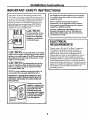 3
3
-
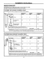 4
4
-
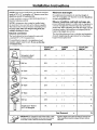 5
5
-
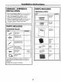 6
6
-
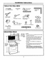 7
7
-
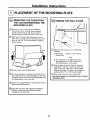 8
8
-
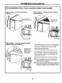 9
9
-
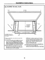 10
10
-
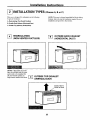 11
11
-
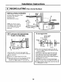 12
12
-
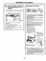 13
13
-
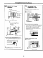 14
14
-
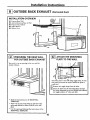 15
15
-
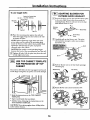 16
16
-
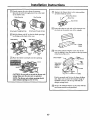 17
17
-
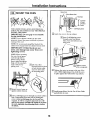 18
18
-
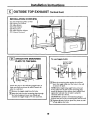 19
19
-
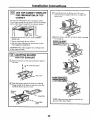 20
20
-
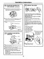 21
21
-
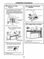 22
22
-
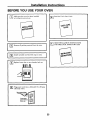 23
23
-
 24
24
-
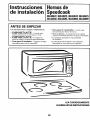 25
25
-
 26
26
-
 27
27
-
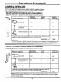 28
28
-
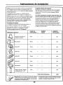 29
29
-
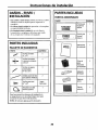 30
30
-
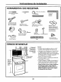 31
31
-
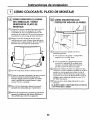 32
32
-
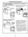 33
33
-
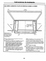 34
34
-
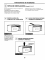 35
35
-
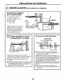 36
36
-
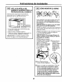 37
37
-
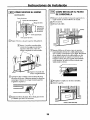 38
38
-
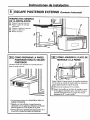 39
39
-
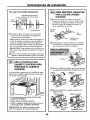 40
40
-
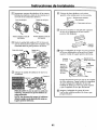 41
41
-
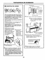 42
42
-
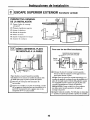 43
43
-
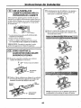 44
44
-
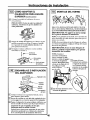 45
45
-
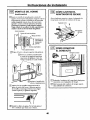 46
46
-
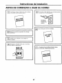 47
47
-
 48
48


Kenmore Elite 36363694301 Guía de instalación
- Categoría
- Microondas
- Tipo
- Guía de instalación
- Este manual también es adecuado para

