Weller C-WSP150 El manual del propietario
- Categoría
- Soldadores
- Tipo
- El manual del propietario

11
®
WSP 150
Operating Instruction
Bruksanvisning
Instrucciones para el Manejo
Betriebsanleitung
Manuel d'Utilisation
Gebruiksaanwijzing
Istruzioni per l'uso
D
F
NL
I
E
GB
S
Wel ler
WSP150_0.301 03.06.2002, 8:43 Uhr11

1
Innehållsförteckning Sidan
1. Beskrivning 8
Tekniska data 8
2. Idrifttagande 8
3. Potentialutjämning 8
4. Arbetstips 8
5. Tillbehör 8
Table of contents Page
1. Description 7
Technical data 7
2. Putting into Operation 7
3. Equipotential Bonding 7
4. Instructions for use 7
5. Accessories 7
Inhoud Pagina
1. Beschrijving 5
Technische gegevens 5
2. Ingebruikneming 5
3. Equipotentiaal 5
4. Werktips 5
5. Toebehoren 5
Table des matières Page
1. Description 4
Caractéristiques techniques 4
2. Mise en service 4
3. Compensation du potentiel 4
4. Instructions d‘emploi 4
5. Accessoires 4
Indice Página
1. Descripción 9
Datos técnicos 9
2. Puesta en funcionamiento 9
3. Compensación de potencial 9
4. Modo operativo Cambio de la punta 9
5. Accesorios 9
Inhaltsverzeichnis Seite
1. Beschreibung 3
Technische Daten 3
2. Inbetriebnahme 3
3. Potentialausgleich 3
4. Arbeitshinweise 3
5. Zubehör 3
Indice Pagina
1. Descrizione 6
Dati tecnici 6
2. Messa in servizio 6
3. Compensazione del potenziale 6
4. Indicazioni operative 6
5. Accessori 6
E
S
GB
I
D
F
NL
WSP150_0.301 03.06.2002, 8:41 Uhr1

2
WSP150_0.301 03.06.2002, 8:41 Uhr2

3
1. Beschreibung
Der Lötkolben WSP 150 wurde speziell für Lötarbeiten mit extrem hohem Wärmebedarf ent-
wickelt. 150 W Heizleistung zusammen mit einer optimalen Wärmeübertragung zur Lötspit-
ze gewährleisten die hohe Leistungsfähigkeit des Lötkolbens. Mit einer integrierten Potential-
ausgleichsleitung besteht die Möglichkeit einen gewünschten Potentialausgleich zur Löt-
spitze herzustellen. Die antistatische Ausführung von Griff und Zuleitung erfüllt die Anforde-
rungen der EGB-Sicherheit.
Technische Daten
Anschlußspannung : 24 V
Leistung : 150 W
Aufheizzeit : ca. 45 sec. (50°C - 350°C)
Max. Temperatur : 550°C
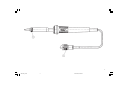
2. Inbetriebnahme
Lötkolben in der Sicherheitsablage ablegen. Alle brennbaren Gegenstände aus der Nähe des
Lötwerkzeugs bringen. Den Anschlußstecker (1) in die Versorgungseinheit einstecken und
verriegeln. An der Versorgungseinheit die gewünschte Temperatur einstellen. Nach Ablauf
der benötigten Aufheizzeit die Lötspitze mit etwas Lot benetzen.
3. Potentialausgleich
Ein gewünschter Potentialausgleich zur Lötspitze kann über das verwendete Versorgungs-
gerät hergestellt werden. Die Anschlußmöglichkeit der Potentialausgleichleitung ist in der
Betriebsanleitung der Versorgungseinheit beschrieben.
4. Arbeitshinweise
Spitzenwechsel
- Lötkolben mit der Spitze leicht nach unten halten.
- Rändelmutter für Spitzenbefestigung (2) lösen.
- Lötspitze liegt nun lose in der Rändelmutter.
Vorsicht: Lötspitze ist heiß!
Den nicht benutzten Lötkolben immer in die Originalablage ablegen.
Antistatische Kunststoffe sind zur Verhinderung von statische Ladung mit leitfähigen Mate-
rialien versehen. Dadurch sind auch die Isoliereigenschaften des Kunststoffes vermindert.
Es dürfen keine Arbeiten an unter Spannung stehenden Teilen durchgeführt werden.
Die Betriebsanleitung der verwendeten Versorgungseinheit ist zu dieser Betriebsanleitung
ergänzend gültig.
5. Zubehör
Siehe Seite 10
D
WSP150_0.301 03.06.2002, 8:41 Uhr3

4
1. Description
Le fer à souder WSP150 a été développé spécialement pour les travaux de soudage requérant
une très forte chaleur. Une puissance calorifique de 150 W et une transmission optimale de
la chaleur vers la panne garantissent l’efficacité du fer à souder. Une ligne d’équipotentialité
intégrée permet d’effectuer une compensation du potentiel avec la panne. L’exécution
antistatique du manche et du cordon d’alimentation est conforme aux exigences de sécurité
pour les composants craignant les décharges électrostatiques.
Caractéristiques Techniques
Tension d’alimentation : 24 V
Puissance : 150 W
Durée de chauffe : env. 45 s (50 °C - 350 °C)
Température maxi. : 550 °C
2. Mise en service
Placer le fer à souder dans le support de sécurité. Eloigner tous les objets inflammables de
l’outil de soudage. Brancher la fiche (1) sur l’unité d’alimentation et la verrouiller. Régler la
température souhaitée sur l’unité d’alimentation. Lorsque la durée de chauffe nécessaire est
écoulée, humecter la panne avec un peu de soudure.
3. Compensation du potentiel
Si on le souhaite, une compensation du potentiel peut être réalisée par l’intermédiaire de
l’unité d’alimentation utilisée. Le branchement de la ligne d’équipotentialité est décrit dans
le mode d’emploi de l’unité d’alimentation.
4. Instructions d’emploi
Changement de panne
- Tenir le fer à souder avec la panne dirigée légèrement vers le bas.
- Dévisser l’écrou moleté de fixation de la panne (2).
- La panne repose maintenant non fixée dans l’écrou moleté.
Attention: La panne est brûlante!
Déposer toujours le fer à souder dans le support d’origine lorsqu’il n’est pas utilisé.
Afin d’éviter les charges statiques, les plastiques antistatiques sont additionnées de substances
conductrices, ce qui réduit leurs propriétés isolantes. Ne jamais travailler sur des éléments
sous tension.
En plus du présent mode d’emploi, observer celui de l’unité d’alimentation utilisée.
5. Accessoires
Voir la page 10
F
WSP150_0.301 03.06.2002, 8:41 Uhr4

5
1. Beschrijving
De soldeerbout WSP150 is speciaal voor soldeerwerkzaamheden met een extreem hoge
warmtebehoefte ontwikkeld. 150 W warmteafgifte samen met een optimale warmtoverdracht
naar de soldeerstift staan garant voor de hoge capaciteit van de soldeerbout. Met een
geïntegreerde equipotentiaalleiding bestaat de mogelijkheid een gewenst equipotentiaal naar
de soldeerstift te produceren. De antistatische uitvoering van greep en snoer voldoen aan de
vereisten van de EGB-veiligheid.
Technische gegevens
Netspanning : 24 V
Capaciteit : 150 W
Opwarmtijd : ca. 45 sec. (50°C - 350°C)
Max. temperatuur : 550°C
2. Ingebruikneming
Leg de soldeerbout in de veiligheidshouder. Haal alle brandbare voorwerpen weg uit de buurt
van het soldeerapparaat. Steek de aansluitstekker (1) in de stroomunit en vergrendel deze.
Stel op de stroomunit de gewenste temperatuur in. Bevochtig na afloop van de benodigde
opwarmtijd de soldeerstift met iets soldeertin.
3. Equipotentiaal
Een gewenst equipotentiaal naar de soldeerstift kan via de gebruikte stroomunit geproduceerd
worden. De aansluitmogelijkheid van de equipotentiaalleiding staat in de gebruikshandleiding
van de stroomunit beschreven.
4. Werktips
Vervangen van de soldeerstift
- Houd de soldeerbout met de stift licht naar beneden
- Maak de kartelmoer voor bevestiging van de stift (2) los
- De soldeerstift ligt nu los in de kartelmoer
Voorzichtig: soldeerstift is heet!
Leg de soldeerbout als hij niet gebruikt wordt altijd in de originele houder.
Antistatische kunststoffen zijn ter voorkoming van statische ladingen voorzien van geleid-
ende materialen. Daardoor worden ook de isolerende eigenschappen van de kunststof
verminderd. Er mogen daarom geen werkzaamheden verricht worden aan onder spanning
staande onderdelen.
De gebruikshandleiding van de gebruikte stroomunit geldt als aanvulling op deze
gebruikshandleiding.
5. Toebehoren
Zie pagina 10
NL
WSP150_0.301 03.06.2002, 8:41 Uhr5

6
1. Descrizione
Lo stilo brasatore WSP 150 è stato progettato in maniera speciale per lavori di brasatura con
un alto fabbisogno di calore. La potenza di 150 W insieme ad un ottimale trasporto di calore
verso la punta di brasatura permettono allo stilo brasatore di raggiungere un alto rendimento.
Con un cavo di compensazione di potenziale integrato esso offre la possibilità di realizzare
una compensazione del potenziale verso la punta di brasatura. L’esecuzione antistatica
dell’impugnatura e del cavo soddisfa i requisiti degli standard EGB.
Dati tecnici
Tensione di collegamento : 24 V
Potenza : 150 W
Tempo di riscaldamento : ca. 45 sec. (50 °C ~ 350 °C)
Temperatura massima : 550 °C
2. Messa in servizio
Riporre lo stilo brasatore nel supporto di sicurezza. Tenere lontani dall’utensile di brasatura
tutti gli oggetti infiammabili. Inserire la spina di collegamento (1) nell’unità di alimentazione
e bloccarla in posizione. Impostare la temperatura desiderata agendo sull’unità di
alimentazione. Allo scadere del tempo di riscaldamento necessario ricoprire con dello stagno
la punta di brasatura.
3. Compensazione del potenziale
Una desiderata compensazione di potenziale verso la punta di brasatura può essere realizzata
attraverso l’apparecchio di alimentazione usato. La possibilità di collegamento del cavo di
compensazione di potenziale è descritta nelle istruzioni di esercizio dell’unità di alimentazione.
4. Indicazioni operative
Sostituzione della punta
- Tenere il brasatura con la punta leggermente rivolta verso il basso.
- Allentare il dado zigrinato per il fissaggio della punta (2).
- La punta di brasatura si trova ora mollata nella vite zigrinata.
Attenzione: la punta di brasatura è calda!
Riporre sempre nel supporto originale lo stilo di brasatura, se non utilizzato.
I materiali sintetici antistatici sono dotati di materiali conduttori al fine di evitare la formazione
di cariche elettrostatiche. In tale maniera vengono ridotte anche le proprietà isolanti del
materiale sintetico. Non devono essere eseguiti lavori su pezzi che si trovano sotto tensione
elettrica.
Complementarmente alle presenti istruzioni hanno anche valore le istruzioni d’uso dell’unità
di alimentazione utilizzata.
5. Accessori
Vedere a pagina 10
I
WSP150_0.301 03.06.2002, 8:41 Uhr6

7
1. Description
The WSP150 soldering iron was specially developed for soldering tasks with extremely high
heat requirements. The 150 W heater power combined with the optimal transfer of heat to
the soldering iron bit guarantee the high performance capability of the soldering iron. Using
an integrated equipotential bonding wire, it is possible to equipotentially bond the soldering
iron bit as required. The anti-static design of the handle and cable comply with the
requirements for electrostatic sensitive device safety.
Technical Data
Supply Voltage : 24 V
Power : 150 W
Warm-Up Time : approx. 45 sec. (50 ºC - 350 ºC)
Max. Temperature : 550 ºC
2. Putting into Operation
Place the soldering iron in the stand. Remove all flammable substances from the area around
the soldering iron. Plug the connector (1) into the supply unit and lock. Set the required
temperature on the supply unit. At the end of the necessary warm-up time, tin the soldering
iron bit with some solder.
3. Equipotential Bonding
If required, the soldering iron bit can be equipotentially bonded via the supply unit used. The
possible ways of connecting the equipotential bonding wire are described in the operating
instructions for the supply unit.
4. Instructions for Use
Bit Changing
- Hold the soldering iron with the bit slightly downwards.
- Undo the knurled bit retaining nut (2).
- The soldering iron bit is now loose in the knurled nut.
Caution: The soldering iron bit is hot!
Always place the soldering iron in the stand when not in use.
Anti-static plastics are treated with conductive material to prevent static charging. This results
in a reduction in the insulating properties of the plastic. It is not permitted to work on live
parts.
The operating instructions for the supply unit used are also applicable in addition to these
operating instructions.
5. Accessories
See page 10
GB
WSP150_0.301 03.06.2002, 8:41 Uhr7

8
1. Beskrivning
Lödkolv WSP 10 har utvecklats speciellt för lödarbeten med extremt högt värmebehov. En
värmeeffekt på 150W tillsammans med en mycket god värmeledningsförmåga till
lödspetsen garanterar lödkolvens höga prestanda. Med hjälp av en
potentialutjämningsledning finn möjlighet att upprätta en önskad potentialutjämning till
lödspetsen. Handtaget och ledningens antistatiska uförande uppfyller kraven på säkerhet
mot anitstatisk elektricitet.
Tekniska data
Anslutningsspänning : 24V
Effekt : 150W
Uppvärmningstid : ca 45 sek. (50°C - 350°C)
Max temperatur : 550°C
2. Idrifttagning
Lägg lödkolven i säkerhetsstället. Avlägsna alla brännbara föremål från lödverktygets
närhet. Stick in och lås anslutningskontakten (1) i försörjningsenheten. Ställ in önskad
temperatur på försörjningsenheten. Fukta lödspetsen med lite lod efter
uppvärmningstiden.
3. Potentialutjämning
Önskad potentialutjämning till lödspetsen kan upprättas via försörjningsenheten.
Anslutningsmöjligheterna för potentialutjämningsledningen är beskrivna i
försörjningsenhetens driftmanual.
4. Arbetstips
Byte av lödspets
- Håll lödskolven med spetsen lätt nedåtlutad
- Lossa handmuttern till spetsfästet (2).
- Lödspetsen ligger nu löst i handmuttern
Varning: lödspetsen är het !
Lägg alltid lödkolven i originalstället när den inte används.
Antistatiska plaster är alltid försedda med elektriskt ledande material för att förhindra statisk
uppladdning. Därigenom minskar palstens isolerande egenskaper. Inga arbeten får utföras
på spänningsförande delar.
Driftmanualen till använd försörjningsenhet gäller som komplettering till denna driftmanual.
5. Tillbehör
Se sidan 10
S
WSP150_0.301 03.06.2002, 8:41 Uhr8

9
1. Descripción
El soldador WSP 150 ha sido especialmente desarrollado para aplicaciones de soldadura
que requieran una temperatura extremadamente alta. 150 W de potencia en conjunto con
una transmisión óptima del calor hacia la punta de soldar garantizan la elevada capacidad
de rendimiento del soldador. Una línea de compensación de potencial integrada ofrece la
posibilidad de establecer una eventualmente deseada compensación de potencial con la
punta para soldar. La ejecución antiestática del mango y de la línea de alimentación cumple
los requisitos impuestos por la normas EGB.
Datos técnicos
Toma de tensión : 24V
Potencia : 150W
Intervalo de calentamiento : aprox. 45seg. (50° - 350°C)
Temperatura máx. : 550°C
2. Puesta en funcionamiento
Colocar el soldador en la base de seguridad. Retirar todos los objetos combustibles de la
cercanía del útil soldador. Enchufar en la unidad de alimentación el conector de toma de
corriente (1) y enclavarlo. Ajustar en la unidad de alimentación la temperatura deseada.
Aplicar un poco del producto soldador a la punta para soldar después de transcurrido el
intervalo de calentamiento.
3. Compensación de potencial
Una compensación de potencial eventualmente deseada puede establecerse a través de la
unidad de alimentación empleada. La posibilidad de conexión de la línea de potencial
compensado se describe en las instrucciones de servicio de la unidad de alimentación.
4. Modo operativo Cambio de la punta
- Mantener el soldador con la punta orientada hacia arriba.
- Aflojar la tuerca moleteada para fijación de la punta (2).
- La punta se encuentra ahora suelta en la tuerca moleteada.
Precaución, la punta para soldar está caliente!
Colocar siempre en sus soportes originales las puntas para soldar que no se usen.
Los plásticos antiestáticos se han previsto con materiales de relleno conductores a fin de
prevenir cargas estáticas. Con ello se reducen igualmente las características aislantes del
plástico. No debe realizarse trabajo alguno en piezas que se encuentren bajo tensión.
Las instrucciones de servicio de la unidad de alimentación rigen de forma complementaria
a laspresentes.
5. Accesorios
Véase página 10
E
WSP150_0.301 03.06.2002, 8:41 Uhr9

10
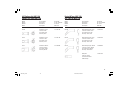
LHT-Spitzen für WSP 150
Pannes LHT pour WSP 150
Modell Beschreibung Bestell-Nr.
Modèle Description N° de commande
Modello Descrizione N° di ord.
Model Description Order-No.
LHT D Meißelform 5 mm 5 44 452 99
Tournevis 5mm
Cacciavite 5mm
Chisel tip 5mm
LHT E Meißelform 7 mm 5 44 451 99
Tournevis 7 mm
Cacciavite 7 mm
Chisel tip 7 mm
LHT F Meißelform 10 mm 5 44 450 99
Tournevis 10 mm
Cacciavite 10 mm
Chisel tip 10 mm
Punte LHT per WSP 150
LHT-Tips for WSP 150
Modell Beschreibung Bestell-Nr.
Modèle Description N° de commande
Modello Descrizione N° di ord.
Model Description Order-No.
LHT DX Meißelform gebogen 5 mm 5 44 462 99
Tournevis courbée 5 mm
Cacciavite curva 5 mm
Chisel tip, bent 5 mm
LHT EX Meißelform gebogen 7 mm 5 44 461 99
Tournevis courbée 7 mm
Cacciavite curva 7 mm
Chisel tip, bent 7 mm
LHT FX Meißelform gebogen 10 mm 5 44 460 99
Tournevis courbée 10 mm
Cacciavite curva 10 mm
Chisel tip, bent 10 mm
Meßspitze 5 44 453 99
Panne de mesure
Punta di misurazione
Calibration tip
WSP150_0.301 03.06.2002, 8:41 Uhr10

12
-
 1
1
-
 2
2
-
 3
3
-
 4
4
-
 5
5
-
 6
6
-
 7
7
-
 8
8
-
 9
9
-
 10
10
-
 11
11
-
 12
12


Weller C-WSP150 El manual del propietario
- Categoría
- Soldadores
- Tipo
- El manual del propietario
En otros idiomas
- français: Weller C-WSP150 Le manuel du propriétaire
- italiano: Weller C-WSP150 Manuale del proprietario
- Deutsch: Weller C-WSP150 Bedienungsanleitung
- Nederlands: Weller C-WSP150 de handleiding
- svenska: Weller C-WSP150 Bruksanvisning
Documentos relacionados
-
Weller WSP 150 Operating Instructions Manual
-
-
-
Weller LR 82 Operating Instructions Manual
-
-
-
-
-
Weller WMP Operating Instructions Manual
-
Weller WP 120 Operating Instructions Manual