La página se está cargando...

Item #1001 223 284
Model #26829
UL Model #CF101H-60
USE AND CARE GUIDE
INDUSTRIAL 60-INCH CEILING FAN
Questions, problems, missing parts? Before returning to the store call
Hampton Bay Customer Service
8 a.m. - 6 p.m., EST, Monday-Friday.
1-855-HD-HAMPTON
HAMPTONBAY.COM
THANK YOU
We appreciate the trust and condence you have placed in Hampton Bay through the purchase of this ceiling fan. We strive to continually create
quality products designed to enhance your home. Visit us online to see our full line of products available for your home improvement needs.
Thank you for choosing Hampton Bay!

2
Table of Contents ................................................................2
Safety Information ...............................................................2
Warranty ............................................................................... 3
Pre-Installation ....................................................................3
Installation ............................................................................6
Assembly ..............................................................................7
Operation ...........................................................................12
Care and Cleaning ............................................................. 13
Troubleshooting .................................................................13
1. All wiring must be in accordance with the National Electrical
Code ANSI/NFPA 70-1999 and local electrical codes. Electrical
installation should be performed by a qualified licensed
electrician.
2. The outlet box and support structure must be securely mounted
and capable of reliably supporting 35 lbs. (15.9kg). Use only UL
Listed outlet boxes marked “Acceptable for Fan Support of 35
lbs. (15.9kg) or less.””
3. The fan must be mounted with a minimum of 10 ft (3 m)
clearance from the trailing edge of the blades to the oor.
4. Do not operate the reversing switch while the fan blades are
in motion. You must turn the fan off and stop the blades before
you reverse the blade direction.
5. Do not place objects in the path of the blades.
6. Electrical diagrams are for reference only.
7. After making electrical connections, spliced conductors should
be turned upward and pushed carefully up into the outlet box.
The wires should be spread apart with the grounded conductor
and the equipment-grounding conductor on one side of the
outlet box.
8. All set screws must be checked and retightened where
necessary before installation.
WARNING: To reduce the risk of personal injury,
do not bend the blade brackets (also referred to as
anges) during assembly or after installation. Do not
insert objects in the path of the blades.
WARNING: To reduce the risk of re or electric
shock, do not use this fan with any solid-state speed
control device.
WARNING: To avoid possible electrical shock,
turn the electricity off at the main fuse box before
wiring. If you feel you do not have enough electrical
wiring knowledge or experience, contact a licensed
electrician.
WARNING: To reduce the risk of shock, this fan must
be installed with a wall-control/switch.
WARNING: To reduce the risk of re, electric shock or
personal injury, wire only a single wall-control panel/
switch and ceiling fan unit together. Wiring two or
more ceiling fans to any wall-control panel/switch
may cause the circuitry to fail by overheating. Please
do not attempt to defeat this feature of the ceiling
fan system as doing so will void the warranty, both
explicit and implicit stipulations thereof.
Safety Information
Table of Contents
CAUTION: To reduce the risk of personal injury,
use only the screws provided with the outlet box.
CAUTION: To avoid personal injury or damage to the fan
and other items, use caution when working around or
cleaning the fan.
WARNING: To reduce the risk of re, electric shock
or personal injury, mount to outlet box marked
“Acceptable for fan support of 35lbs. (15.9kg) or
less”, and use screws provided with the outlet box.

3
HAMPTONBAY.COM
Please contact 1-855-HD-HAMPTON for further assistance.
Pre-Installation
Warranty
The supplier warrants the fan motor to be free from defects in workmanship and material present at time of shipment from the factory for a life-
time after the date of purchase by the original purchaser. The supplier also warrants that all other fan parts, excluding any glass or acrylic blades,
to be free from defects in workmanship and material at the time of shipment from the factory for a period of two years after the date of purchase
by the original purchaser. We agree to correct such defects without charge or at our option replace with a comparable or superior model if the
product is returned. To obtain warranty service, you must present a copy of the receipt as proof of purchase. All costs of removing and reinstalling
the product are your responsibility. Damage to any part such as by accident or misuse or improper installation or by afxing any accessories, is
not covered by this warranty. Because of varying climatic conditions this warranty does not cover any changes in brass nish, including rusting,
pitting, corroding, tarnishing, or peeling. Brass nishes of this type give their longest useful life when protected from varying weather conditions.
A certain amount of “wobble” is normal and should not be considered a defect. Servicing performed by unauthorized persons shall render the
warranty invalid. There is no other express warranty. Hampton Bay hereby disclaims any and all warranties, including but not limited to those
of merchantability and tness for a particular purpose to the extent permitted by law. The duration of any implied warranty which cannot be
disclaimed is limited to the time period as specied in the express warranty. Some states do not allow a limitation on how long an implied war-
ranty lasts, so the above limitation may not apply to you. The retailer shall not be liable for incidental, consequential, or special damages arising
out of or in connection with product use or performance except as may otherwise be accorded by law. Some states do not allow the exclusion of
incidental or consequential damages, so the above exclusion or limitation may not apply to you. This warranty gives specic legal rights, and you
may also have other rights which vary from state to state. This warranty supersedes all prior warranties. Shipping costs for any return of product
as part of a claim on the warranty must be paid by the customer.
Contact the Customer Service Team at 1-855-HD-HAMPTON or visit www.HamptonBay.com
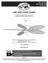
SPECIFICATIONS
TOOLS REQUIRED
NOTE: Measured according to Energy STAR
®
approved
Solid State test method.
Phillips
screwdriver
Flat blade
screwdriver
Adjustable
wrench
Electrical
tape
Wire
cutter
Step ladder
Size Speed Volts Amps
Power
Use
(WATT)
RPM
Airow
CFM
Airow Efciency
(Higher Is Better)
CFM/WATT
Net
Weight
Gross
Weight
Cube Feet
60 in.
Low
120
0.4 15 89 3208 213
17.64 lbs
(8 kgs)
19.82 lbs
(8.99 kgs)
1.66’
Medium 0.58 32 137 4961 155
High 1 0.87 75 211 7990 106
High 2 0.99 109 247 9602 89

4
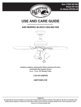
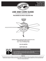
Part Description Quantity
AA J wood screw 1
BB Canopy mounting screw 4
CC Canopy mounting lock washer 4
DD Plastic wire connector 6
EE Hanger bolt 1
FF Flat washer 1
GG Hexagonal nut 1
HH Lockwasher 1
Part Description Quantity
II Control mounting screw 2
JJ Control mounting screw 2
KK Lockwasher 6
LL Flat washer 6
MM Screw 6
NN Split pin 1
Pre-Installation (continued)
HARDWARE INCLUDED
NOTE: Hardware not shown to actual size.
AA
BB
FF
KK LL MM NN
GG HH II JJ
CC
DD EE

5
HAMPTONBAY.COM
Please contact 1-855-HD-HAMPTON for further assistance.
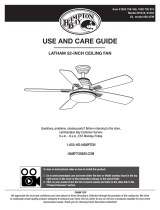
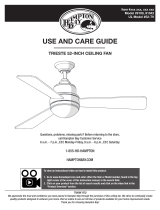
Part Description Quantity
A Mounting bracket 1
B Ball/downrod assembly 1
C Canopy 1
D Coupler cover 1
Part Description Quantity
E Blade 3
F Wall control 1
G Motor 1
IMPORTANT: This product and/or components are
governed by one or more of the following U.S. Patents:
5,947,436; 5,988,580; 6,010,110; 6,046,416, 6,210,117
and other patents pending.
Pre-Installation (continued)
PACKAGE CONTENTS
A
B
C
D
E
F
G

6
Installation
MOUNTING OPTIONS
WARNING: To reduce the risk of re, electric shock
or personal injury, mount to outlet box marked
“Acceptable for fan support of 35lbs. (15.9kg) or less”,
and use screws provided with the outlet box. An outlet
box commonly used for the support of lighting xtures
may not be acceptable for fan support and may need to
be replaced. If in doubt, consult a qualied electrician.
If your ceiling fan does not have an existing UL-listed mounting
box, then install one using the following instructions:
□ Disconnect the power by removing the fuses or turning off
the circuit breakers.
□ Secure the outlet box directly to the building structure.
Use the appropriate fasteners and materials. The outlet
box and support structure must be securely mounted and
capable of reliably supporting 35 lbs. (15.9kg). Use only UL
Listed outlet boxes marked “Acceptable for Fan Support of
35 lbs. (15.9kg) or less.”. Do not use a plastic outlet box.
The illustrations below show three different ways to mount the
outlet box.
If the canopy touches the downrod, then remove the decorative canopy
bottom cover, and turn the canopy 180° before attaching the canopy to
the mounting plate.
To hang your fan where there is an existing xture but no ceiling joist,
you may need an installation hanger bar as shown above
(available at any Home Depot store).
NOTE: You may need a longer downrod to maintain
proper blade clearance when installing on a steep, sloped
ceiling. The maximum angle allowable is 30° away from
horizontal.
Outlet Box
Outlet Box
Recessed
Outlet
Box
Provide Strong
Support
Ceiling
Mounting
Plate
Outlet Box
Hanger Bar

7
HAMPTONBAY.COM
Please contact 1-855-HD-HAMPTON for further assistance.
Assembly
Installing the downrod
□ Route the wires exiting the top of the motor housing (G)
through the downrod (B).
□ Insert the downrod (B) into the coupler (J) on the top of the
motor housing (G).
□ Align the holes at the bottom of the downrod (B) with the holes
in the coupler (J) and insert the hanger bolt (EE).
□ Secure the hanger bolt (EE) using the at washer (FF),
lockwasher (HH), and the hexagonal nut (GG).
□ Insert the split pin (NN) into the end of the hanger bolt (EE) and
split the ends of the split pin (NN) apart to secure the hanger
bolt (EE).
□ Tighten the set screw (ZZ) rmly.
2
B
NN
G
GG
FF
HH
J
EE
ZZ
Dismantling the ball/downrod
assembly
□ Loosen the hanger ball (H) by removing the set screw
(PP) and lockwasher (QQ) at the top of the downrod (B)
which holds the hanger ball to the downrod.
□ Slide the hanger ball (H) down the downrod (B) and
remove the support pin (RR).
□ Unscrew the green groundwire (I) located at the top of
the downrod (B) by unscrewing the screw (SS) on the
downrod (B).
1
I
PP
QQ
H
SS
RR

8
Assembly (continued)
Assembly - Hanging the Fan
Installing the coupler cover and
canopy
□ Slide the coupler cover (D) onto the downrod (B) and push the
coupler cover (D) until it rests on the top of the motor housing
(G).
□ Tighten the set screw (ZZ) to secure the coupler cover (D) onto
the downrod (B).
□ Slide the canopy (C) onto the downrod (B).
3
D
B
ZZ
G
C
Installing the ball on the downrod
Installing the mounting bracket
□ Pass the 120-Volt supply wires through the center hole in the
mounting bracket (A).
□ Install the ceiling mounting plate on the outlet box by sliding the
mounting bracket (A) over the two screws (TT) provided with the
outlet box. If necessary, use leveling washers (not included) be-
tween the mounting bracket (A) and the outlet box. Note that the
at side of the mounting bracket (A) is toward the outlet box.
□ Securely tighten the two mounting screws (TT).
4
5
WARNING: To reduce the risk of re, electric shock
or personal injury, mount to outlet box marked
“Acceptable for fan support of 35lbs. (15.9kg) or
less”, and use screws provided with the outlet box.
TT
A
TT
□ Slide the hanger ball (H) onto the top of the downrod
(B) past the holes in the downrod (B).
□ Replace the support pin (RR) into the holes located at
the top of the downrod (B).
□ Slide the ball (H) up and align the holes in the ball (H)
and downrod (B). Make sure the support pin (RR) aligns
in the slot of the ball (H).
□ Screw the set screw (PP) and lockwasher (QQ) into the
hole in the ball (H) and downrod (B) to secure the ball.
□ Reattached the green ground wire (I) to the downrod
using the screw (SS) and washer that were removed in
step 1.
I
PP
B
QQ
H
SS
RR

9
HAMPTONBAY.COM
Please contact 1-855-HD-HAMPTON for further assistance.
Assembly - Hanging the Fan (continued)
Connecting the safety cable
□ Turn the wood screw (AA) into the ceiling.
□ Place the looped end of the safety cable (K) onto the wood
screw (AA) and then tighten the screw rmly, or connect the
safety cable directly to the outer joist or mounting bracket (A).
7
AA
K
A
Hanging the fan
□ Carefully lift the fan motor assembly (G) up to the mounting
bracket (A).
□ Seat the hanger ball portion of the ball/downrod assembly (B)
in the mounting bracket socket. Ensure that the tab on the
mounting bracket (A) socket is properly seated in the groove
in the hanger ball (B).
6
A
B
G
Attaching the canopy
□ Align the locking slots of the ceiling canopy (C) with the two
screws in the mounting bracket (A). Push up to engage the
slots, and turn clockwise to lock the canopy (C) in place.
□ Firmly tighten the two mounting screws (BB) with lock washer
(CC).
□ Install the remaining two mounting screws (BB) into the holes
in the canopy (C) and tighten rmly.
8
WARNING: When using the standard ball/downrod mounting, the
tab in the ring at the bottom of the mounting bracket must rest in
the groove of the hanger ball. Failure to properly seat the tab in
the groove could cause damage to the wiring.
C
BB
A

10
UU
VV
WW
WW
WW
XX
UU
VV
Assembly - Hanging the Fan (continued)
Making the electrical connection
□ Connect the ground conductor of the 120-Volt supply (this
may be a bare wire or a wire with green colored insulation) to
the green ground lead(s) (UU) of the fan.
□ Connect the fan motor white wire (VV) to the supply white wire
(VV) using a wire connecting nut (DD).
□ Connect the fan motor black wire (WW) to the supply black
wire (WW) using a wire connecting nut (DD).
□ After connecting the wires, spread them apart so that the
green (UU) and white wires (VV) are one side of the outlet box
(XX) and the black wire (WW) is on the other side.
□ Turn the wire connecting nuts upward, and carefully push the
wiring into the outlet box (XX).
9
IMPORTANT: Use the wire connecting nuts (DD) supplied with
your fan. Secure the connectors with electrical tape and ensure
there are no loose strands or connections.
WARNING: Each wire not supplied with this fan is designed to
accept up to one 12-gauge house wire and two wires from the
fan. If you have larger than 12-gauge house wiring or more
than one house wire to connect to the fan wiring, consult an
electrician for the proper size wire nuts to use.
Assembly (continued)
Attaching the fan blades
10
□ Position the blade assembly (E) on the motor so the
mounting screw holes align with the threaded holes.
□ Turn the screw (MM), spring washer (KK), and at washer
(LL) into the hole but do not completely tighten. Make sure
the second hole in the blade assembly aligns with a hole in
the motor housing (G).
□ Install a second screw (MM), spring washer (KK) and at
washer (LL) in the blade assembly in the same manner.
□ Repeat for the remaining blades.
□ Tighten all screws.
G
E
MM
KK
LL
NOTE: The blade and blade arms are pre-assembled
together at the factory. The blades feature new technology
for higher efciency. The blades are not reversible.

11
HAMPTONBAY.COM
Please contact 1-855-HD-HAMPTON for further assistance.
Operation
Install 4-speed wall control
Operating your fan
The reverse switch is located on the coupler (J).
To switch the direction of the blade rotation, follow the instructions
below.
□ Loosen the set screw (O) on the coupler cover (D).
□ Slide coupler cover (D) up to reveal the coupler (J) and reverse
switch (YY).
□ Set reverse switch (YY) in desired direction:
For warm weather, set switch in down position.
For cool weather, set switch in up position.
See the instructions enclosed with the wall control package.
Warm weather - (Forward) A downward airow creates a cooling ef-
fect. This allows you to set your air conditioner on a warmer setting
without affecting your comfort.
Cool weather - (Reverse) An upward airow moves warm air off of
the ceiling. This allows you to set your heating unit on a cooler set-
ting without affecting your comfort.
NOTE: Wait for the fan to completely stop before setting the slide
switch to reverse the direction of blade rotation.
D
J
YY
O

12
Troubleshooting
Problem Solution
The fan will not start □ Check the main and branch circuit fuses or breakers.
□ Check the line wire connections to the fan and switch wire connections in the switch housing.
The fan is noisy □ Ensure all motor housing screws are snug.
□ Ensure the screws that attach the fan blade bracket to the motor hub are tight.
□ Ensure the wire nut connections are not rattling against each other or the interior wall of the switch housing.
□ Allow a 24-hour “breaking in” period. Most noises associated with a new fan disappear during this time.
□ If you are using the Ceiling Fan light kit, ensure the screws securing the glassware are tight. Check that the light
bulbs are also secure.
□ Ensure the canopy is a short distance from the ceiling. It should not touch the ceiling.
□ Ensure your outlet box is secure and rubber isolator pads were used between the mounting plate and outlet box.
The fan wobbles □ Check that all blade and blade arm screws are secure.
□ Most fan wobble problems are caused when blade levels are unequal. Check this level by selecting a point on
the ceiling above the tip of one of the blades. Measure from a point on the center of the blade to the point on the
ceiling. Rotate the fan until the next blade is positioned for measurement, and measure from the same point on
each blade to the ceiling. Repeat for each blade. Any measurement deviation should be within 1/8 in. Run the fan
for ten minutes. If the fan continues to wobble please contact Customer Service and a balancing kit will be sent
to you at no charge.
□ Because of the fan’s natural movement, some connections may become loose. Check the support connections, brackets, and blade
attachments twice a year. Make sure they are secure. It is not necessary to remove the fan from the ceiling.
□ Clean your fan periodically to help maintain its new appearance over the years. Do not use water when cleaning, as this could damage
the motor, or the wood, or possibly cause an electrical shock. Use only a soft brush or lint-free cloth to avoid scratching the nish. The
plating is sealed with a lacquer to minimize discoloration or tarnishing.
□ You can apply a light coat of furniture polish to the wood for additional protection and enhanced beauty. Cover small scratches with a
light application of shoe polish.
□ You do not need to oil your fan. The motor has permanently-lubricated sealed ball bearings.
WARNING: Make sure the power is off before cleaning
your fan.
Care and Cleaning

Questions, problems, missing parts? Before returning to the store call
Hampton Bay Customer Service
8 a.m. - 6 p.m., EST, Monday-Friday
1-855-HD-HAMPTON
HAMPTONBAY.COM
Retain this manual for future use.

Artículo Núm.1001 223 284
Modelo Núm. 26829
Modelo núm. CF101H-60
Aprobado por UL
GUÍA DEUSO YMANTENIMIENTO
VENTILADOR DETECHO, INDUSTRIAL, DE1,72 M
¿Preguntas, problemas opiezas faltantes? Antes deregresar alatienda,
llama alServicio alCliente deHampton Bay
deLunes aViernes entre 8 a.m. y6 p.m., (hora del Este deEE. UU.)
1-855-HD-HAMPTON
HAMPTONBAY.COM
GRACIAS POR TUCOMPRA
Apreciamos laconanza que has depositado enHampton Bay alcomprar este ventilador detecho. Nos esforzamos para continuamente crear productos
decalidad diseñados para tuhogar. Visítanos por Internet para ver nuestra línea completa deproductos disponibles para las necesidades demejoras detuhogar.
¡Gracias por elegir Hampton Bay!

2
Tabla deContenido .............................................................2
Información deSeguridad ..................................................2
Garantía ................................................................................3
Pre-Instalación..................................................................... 3
Instalación ............................................................................6
Ensamblaje ...........................................................................7
Funcionamiento .................................................................12
Mantenimiento yLimpieza................................................13
Solución deProblemas ..................................................... 13
1. Todo elcableado debe cumplir con elCódigo Nacional
deElectricidad ANSI/NFPA 70-1999 ycon los códigos locales
deelectricidad. Lainstalación eléctrica debe ser hecha por
unelectricista certificado ycalificado.
2. La caja eléctrica y estructura de soporte deben montarse de
forma segura y tener capacidad para sostener de manera
conable 35 lb. Usa solamente cajas eléctricas aprobadas por
UL marcadas como “Aprobada como soporte de ventiladores
de 35 lb (15,9kg) o menos.”
3. Elventilador debe irmontado con unmínimo de10 pies (3 m)
deseparación entre elborde trasero delas aspas yelpiso.
4. Nomuevas elinterruptor dereversa mientras las aspas del
ventilador estén enmovimiento. Debes apagar elventilador
ydetener las aspas antes deinvertir ladirección delas aspas.
5. Nocoloques objetos enlatrayectoria delas aspas.
6. Los diagramas eléctricos son sólo para referencia.
7. Después deconcluir con las conexiones eléctricas, debes
voltear los conductores empalmados hacia arriba ymeterlos
con cuidado enlacaja eléctrica. Los cables deben estar
separados, con elcable atierra yelconductor atierra del
equipo enuno delos lados delacaja eléctrica.
8. Todos los tornillos colocados sedeben verificar yajustar
donde sea necesario, antes delainstalación.
ADVERTENCIA: Para reducir el riesgo de lesiones,
nodobles los soportes delas aspas (también llamados
“bridas”) durante o después de la instalación.
No coloques ningún objeto en la trayectoria de las
aspas.
ADVERTENCIA: Para reducir el riesgo de incendio
o descarga eléctrica, no utilices este ventilador con
ningún dispositivo decontrol develocidad deestado
sólido.
ADVERTENCIA: Para evitar una posible descarga
eléctrica, apaga la electricidad en la caja principal
de fusibles antes de instalar el cableado. Si crees
que notienes suciente experiencia oconocimientos
sobre cableado eléctrico, contrata aunelectricista con
licencia.
ADVERTENCIA: Para reducir el riesgo de descarga,
este ventilador se debe instalar con un
control/interruptor depared.
ADVERTENCIA: Para disminuir los riesgos deincendio,
descarga eléctrica o lesiones, conecta un solo
control/interruptor de pared al ventilador de techo.
La conexión de dos o más ventiladores de techo
a cualquier panel/interruptor del control de pared
puede recalentar y provocar fallas en los circuitos
eléctricos. Nointentes ignorar esta característica del
sistema del ventilador detecho, yaque hacerlo anulará
las estipulaciones delagarantía, tanto explícitas como
implícitas.
Información deSeguridad
Tabla deContenido
PRECAUCIÓN: Para reducir elriesgo delesiones,
usa sólo los tornillos incluidos con lacaja eléctrica.
PRECAUCIÓN: Para evitar lesiones físicas o daños
al ventilador y otros artículos, ten cuidado al limpiar
otrabajar cerca del ventilador.
ADVERTENCIA: Para reducir el riesgo de incendio,
descarga eléctrica o lesiones personales, monta el
ventilador sobre una caja eléctrica marcada como
“aprobada como soporte de ventiladores de 35 lb
(15,9kg) o menos”, y usa los tornillos de montaje que
vienen con la misma.

3
HAMPTONBAY.COM
Para obtener asistencia, llama al 1-855-HD-HAMPTON.
Pre-Instalación
Garantía
El proveedor garantiza depor vida, apartir delafecha enque elcomprador original loadquiere, que elmotor del ventilador nopresenta defectos
defabricación nidematerial almomento enque esenviado desde lafábrica. Elproveedor también garantiza por unperíodo dedos años apartir
delafecha decompra por elcomprador original, que todas las demás piezas del ventilador, sin incluir ninguna aspa devidrio oacrílico, nopresentarán
ningún defecto defabricación odematerial desde elmomento desusalida delafábrica. Acordamos reparar todos los defectos del tipo antes mencionado,
sin cargo alguno, oanuestra discreción, reemplazar elproducto por unmodelo decalidad comparable osuperior sielproducto esdevuelto. Para obtener
unservicio degarantía, debe presentar una copia del recibo como comprobante decompra. Todos los costos deretiro yreinstalación del producto
son suresponsabilidad. Los daños acualquiera delas piezas como resultado deaccidentes, instalación ouso incorrectos, odebidos alainstalación
decualquier accesorio, noestán cubiertos bajo esta garantía. Debido aque las condiciones climáticas pueden variar, esta garantía nocubre ningún
cambio enelacabado enbronce, incluyendo óxido, perforación, corrosión, manchas odescascaramiento. Los acabados enbronce deeste tipo tienen
una vida útil más prolongada cuando seprotegen delas condiciones climáticas cambiantes. Esnormal cierta “oscilación” ynoseconsiderará una
falla. Cualquier servicio técnico conducido por personas noautorizadas anulará lagarantía. Nohay ninguna otra garantía expresa. Mediante lapresente
Hampton Bay seexime decualquier garantía, incluyendo pero sin limitarse aaquellas decomercialización eidoneidad para unn particular, deacuerdo
alocontemplado por laley. Laduración decualquier garantía implícita delacual nosepueda eximir, está limitada alperíodo detiempo especicado
enlagarantía explícita. Algunos estados nopermiten limitaciones enladuración delagarantía implícita, por consiguiente lalimitación anterior puede
noaplicarse asucaso. Elminorista noserá responsable por daños directos, indirectos oespeciales que resulten oderiven del uso orendimiento del
producto excepto encasos enque loestipule laley. Algunos estados nopermiten laexclusión olimitación dedaños directos oindirectos, por loque
lalimitación oexclusión anterior podría noaplicarse austed. Esta garantía leotorga derechos legales especícos pero esposible que también tenga otros
derechos que varían deunestado aotro. Esta garantía sustituye todas las garantías anteriores. Los costos deenvío decualquier devolución deproductos
hecha como parte deuna reclamación degarantía deben ser pagados por elcliente.
Comuníquese con elEquipo deServicio alCliente por el1-855-HD-HAMPTON ovisite www.HamptonBay.com
ESPECIFICACIONES
HERRAMIENTAS NECESARIAS
NOTA: Medida deacuerdo almétodo deprueba
deEstado Sólido, aprobado por Energy STAR
®
.
Destornillador
Phillips
Destornillador
plano
Llave
ajustable
Cinta
deelectricista
Cortacables
Escalera
Tamaño Velocidad Voltios Amperios
Consumo
de
Energía
(WATTS)
RPM
Flujo
deAire
PIES
CÚB.
XMIN.
Eciencia deFlujo
deAire (Mientras
Más Alta, Mejor)
PIES CÚB
XMIN./VATIOS
Peso
Neto
Peso
Bruto
Pies
Cúbicos
1,52 m
Baja
120
0,4 15 89 3 208 213
17,64 lb
(8 Kg)
19,82 lb
(8,99 Kg)
1,66’
Media 0,58 32 137 4 961 155
Alta 1 0,87 75 211 7 990 106
Alta 2 0,99 109 247 9 602 89

4
Pieza Descripción Cantidad
AA Tornillo para madera enforma deJ 1
BB Tornillo demontaje delacubierta 4
CC Arandela deseguridad de
montaje delacubierta
4
DD Conector plástico para cable 6
EE Perno para gancho 1
FF Arandela plana 1
GG Tuerca hexagonal 1
HH Arandela deseguridad 1
Pieza Descripción Cantidad
II Tornillo demontaje del control 2
JJ Tornillo demontaje del control 2
KK Arandela deseguridad 6
LL Arandela plana 6
MM Tornillo 6
NN Pasador hendido 1
Pre-Instalación (continuación)
HERRAJES INCLUIDOS
NOTA: Nosemuestra eltamaño real delos herrajes.
AA
BB
FF
KK LL MM NN
GG HH II JJ
CC
DD EE

5
HAMPTONBAY.COM
Para obtener asistencia, llama al 1-855-HD-HAMPTON.
Pieza Descripción Cantidad
A Soporte demontaje 1
B Ensamblaje detubo bajante/bola 1
C Cubierta 1
D Tapa del acoplador 1
Pieza Descripción Cantidad
E Aspa 3
F Control depared 1
G Motor 1
IMPORTANTE: Este producto y/o sus componentes están
protegidos por una omás delas siguientes Patentes:
5,947,436; 5,988,580; 6,010,110; 6,046,416, 6,210,117
yotras patentes pendientes.
Pre-Instalación (continuación)
CONTENIDO DEL PAQUETE
A
B
C
D
E
F
G

6
Instalación
OPCIONES DEMONTAJE
ADVERTENCIA: Para reducir el riesgo de incendio, descarga
eléctrica o lesiones personales, monta el ventilador sobre
una caja eléctrica marcada como “aprobada como soporte de
ventiladores de 35 lb (15,9kg) o menos”, y usa los tornillos de
montaje que vienen con la misma. Las cajas eléctricas utilizadas
comúnmente para elsoporte delámparas podrían noservir
como soporte deventilador, ytal vez deban reemplazarse.
Encaso deduda, consulta aunelectricista calicado.
Si tuventilador detecho notiene una caja demontaje aprobada
por UL, instala una siguiendo las instrucciones acontinuación:
□ Desconecta laenergía retirando los fusibles oapagando
los cortacircuitos.
□ Asegura lacaja eléctrica directamente alaestructura del
edicio. Usa sujetadores ymateriales apropiados. Lacaja
eléctrica ysusoporte deben sostener elpeso completo
del ventilador enmovimiento (al menos 35 lb). Nouses
una caja eléctrica deplástico.
Las ilustraciones acontinuación muestran tres formas
diferentes demontar lacaja eléctrica.
Si lacubierta toca eltubo bajante, retira latapa inferior
decorativa delacubierta ygira lacubierta 180º antes
dejarla alaplaca demontaje.
Para colgar elventilador donde yahaya una lámpara
pero ninguna viga detecho, tal vez necesites una barra
colgante como se muestra anteriormente
(disponible encualquier tienda deThe Home Depot).
NOTA:Tal vez necesites untubo bajante más largo para
mantener laaltura mínima adecuada delas aspas,
alinstalar elventilador enuntecho inclinado. Elángulo
máximo permitido esde30º delaposición horizontal.
Caja Eléctrica
Caja Eléctrica
Caja
Eléctrica
Empotrada
Dar Apoyo
Estable
Placa de
Montaje
de Techo
Caja Eléctrica
Barra Colgante

7
HAMPTONBAY.COM
Para obtener asistencia, llama al 1-855-HD-HAMPTON.
Ensamblaje
Cómo instalar eltubo bajante
□ Inserta los cables que salen por laparte superior delacarcasa
del motor (G) através del tubo bajante (B).
□ Inserta eltubo bajante (B) enelacoplador (J) enlaparte
superior delacarcasa del motor (G).
□ Alinea los oricios enlaparte inferior del tubo bajante (B) con los
oricios enelacoplador (J) einserta elperno para gancho (EE).
□ Asegura elperno para gancho (EE) usando laarandela plana (FF),
laarandela deseguridad (HH) ylatuerca hexagonal (GG).
□ Inserta elpasador hendido (NN) enelextremo del perno para
gancho (EE) ysepara los extremos del pasador hendido (NN)
para asegurar elperno para gancho (EE).
□ Aprieta rmemente eltornillo deajuste (ZZ).
2
B
NN
G
GG
FF
HH
J
EE
ZZ
Cómo desmantelar elensamblaje
del tubo bajante/bola
□ Aoja labola desoporte (H) quitando eltornillo
deajuste (PP) ylaarandela deseguridad (QQ)
enlaparte superior del tubo bajante (B) que sujeta
labola desoporte hasta eltubo bajante.
□ Desliza labola desoporte (H) por eltubo bajante (B)
yretira elpasador desoporte (RR).
□ Desenrosca elcable verde atierra (I) ubicado
enlaparte superior detubo bajante (B) quitando
eltornillo (SS) del mismo.
1
I
PP
QQ
H
SS
RR

8
Ensamblaje (continuación)
Ensamblaje — Colgar elVentilador
Cómo instalar latapa del
acoplador ylacubierta
□ Coloca latapa del acoplador (D) eneltubo bajante (B)
yempuja latapa del acoplador (D) hasta que descanse
enlaparte superior delacarcasa del motor (G).
□ Aprieta eltornillo deajuste (ZZ) para asegurar latapa
del acoplador (D) eneltubo bajante (B).
□ Desliza lacubierta (C) hacia eltubo bajante (B).
3
D
B
ZZ
G
C
Cómo instalar labola
eneltubo bajante
Cómo instalar elsoporte demontaje
□ Pasa los cables desuministro de120 Voltios através del
oricio central enelsoporte demontaje (A).
□ Instala laplaca demontaje detecho sobre lacaja eléctrica
deslizando elsoporte demontaje (A) sobre los dos tornillos (TT)
suministrados con lacaja eléctrica. Siesnecesario, usa arandelas
niveladoras (no incluidas) entre elsoporte demontaje (A) ylacaja
eléctrica. Fíjate que ellado plano del soporte demontaje (A) esté
hacia lacaja eléctrica.
□ Ajusta rmemente los dos tornillos demontaje (TT).
4
5
ADVERTENCIA: Para reducir elriesgo deincendio,
descarga eléctrica olesiones físicas, sólo instala
elventilador enuna caja eléctrica osistema
desoporte aprobados para ventiladores yusa los
tornillos demontaje que vienen con lacaja eléctrica.
TT
A
TT
□ Desliza labola desoporte (H) enlaparte superior del tubo
bajante (B), pasando los oricios eneltubo bajante (B).
□ Vuelve acolocar elpasador desoporte (RR) enlos oricios
del extremo superior del tubo bajante (B).
□ Desliza labola (H) hacia arriba yalinea los oricios
delamisma ydel tubo bajante (B). Asegúrate deque elpasador
desoporte (RR) sealinee enlaranura delabola (H).
□ Atornilla eltornillo deajuste (PP) ylaarandela deseguridad
(QQ) eneloricio delabola (H) yeltubo bajante (B) para
asegurar labola.
□ Vuelve aconectar elcable verde atierra (I) altubo bajante
usando eltornillo (SS) ylaarandela que sequitaron
enelpaso 1.
I
PP
B
QQ
H
SS
RR

9
HAMPTONBAY.COM
Para obtener asistencia, llama al 1-855-HD-HAMPTON.
Ensamblaje — Colgar elVentilador (continuación)
Cómo conectar elcable deseguridad
□ Enrosca eltornillo para madera (AA) eneltecho.
□ Coloca elextremo enbucle del cable deseguridad (K) sobre
eltornillo para madera (AA) yluego aprieta rmemente
eltornillo, oconecta elcable deseguridad directamente
alaviga externa oalsoporte demontaje (A).
7
AA
K
A
Cómo colgar elventilador
□ Con cuidado alza elensamblaje del motor del ventilador (G)
hasta elsoporte demontaje (A).
□ Coloca labola desoporte del ensamblaje del tubo
bajante/bola (B) enelsoporte demontaje. Asegúrate deque
lapestaña sobre elsoporte demontaje (A) encaje bien dentro
delaranura delabola desoporte (B).
6
A
B
G
Cómo montar lacubierta
□ Alinea las ranuras decierre delacubierta detecho (C) con los
dos tornillos del soporte demontaje (A). Alza para enganchar
enlas ranuras ygira deizquierda aderecha para asegurar
lacubierta (C) ensusitio.
□ Ajusta rmemente los dos tornillos demontaje (BB)
con laarandela deseguridad (CC).
□ Instala los dos tornillos demontaje (BB) restantes
enlos oricios delacubierta (C) yaprieta rmemente.
8
ADVERTENCIA: Cuando uses elmontaje detubo bajante ybola
estándar, lapestaña enelaro enlaparte inferior del soporte
demontaje debe encajar enlaranura delabola desoporte.
Silapestaña noseasienta correctamente enlaranura,
sepuede dañar elcableado.
C
BB
A

10
UU
VV
WW
WW
WW
XX
UU
VV
Ensamblaje — Colgar elVentilador (continuación)
Cómo hacer las conexiones eléctricas
□ Conecta elconductor atierra del cable de120 Voltios (puede
ser uncable desnudo ouncable con aislante verde) al(los)
cable(s) terminal(es) atierra verde(s) (UU) del ventilador.
□ Conecta elcable blanco del motor del ventilador (VV) alcable
blanco desuministro deenergía (VV) usando una tuerca
decable (DD).
□ Conecta elcable negro del motor del ventilador (WW) alcable
negro desuministro deenergía (WW) usando una tuerca
decable (DD).
□ Después deconectar los cables, sepáralos demanera que los
cables verde (UU) yblanco (VV) queden deunlado delacaja
eléctrica (XX) yelcable negro (WW) del otro.
□ Gira las tuercas deconexión del cable hacia arriba ycon
cuidado coloca elcableado dentro delacaja eléctrica (XX).
9
IMPORTANTE: Usa las tuercas deconexión decables (DD) que vienen
con tuventilador. Sujeta los conectores con cinta deelectricista
yasegúrate deque nohayan conexiones ocables sueltos.
ADVERTENCIA: Cada cable nosuministrado con este ventilador
está diseñado para aceptar unmáximo deunsolo circuito eléctrico
doméstico decalibre 12 ydos cables del ventilador. Sitienes
uncableado doméstico decalibre superior a12 omás deuncable
doméstico para conectar elcableado del ventilador, consulta
aunelectricista para eltamaño adecuado detuercas decable.
Ensamblaje (continuación)
Cómo montar las aspas del ventilador
10
□ Coloca elensamblaje delas aspas (E) enelmotor detal
manera que oricios delos tornillos demontaje queden
alineados con los oricios roscados.
□ Inserta eltornillo (MM), laarandela deresorte (KK)
ylaarandela plana (LL) eneloricio pero nolos ajustes
completamente. Asegúrate deque elsegundo oricio
enelensamblaje delas aspas está alineado con unoricio
enlacarcasa del motor (G).
□ Delamisma manera, coloca unsegundo tornillo
(MM), arandela deresorte (KK) yarandela plana (LL)
enelensamblaje delas aspas.
□ Repite para las aspas restantes.
□ Ajusta todos los tornillos.
G
E
MM
KK
LL
NOTA: Las aspas ylos brazos delas aspas vienen previamente
ensambladas defábrica. Las aspas presentan tecnología nueva
más eciente. Las aspas noson reversibles.

11
HAMPTONBAY.COM
Para obtener asistencia, llama al 1-855-HD-HAMPTON.
Funcionamiento
Instala elcontrol depared de4 velocidades
Cómo operar elventilador
El interruptor dereversa está ubicado enlasupercie del
acoplador (J).
Para invertir ladirección degiro delas aspas, sigue las
instrucciones acontinuación.
□ Aoja eltornillo deajuste (O) para asegurar latapa del
acoplador (D).
□ Desliza latapa del acoplador (D) hacia arriba para acceder
alacoplador (J) yalinterruptor dereversa (YY).
□ Coloca elinterruptor dereversa (YY) enladirección deseada:
para clima cálido, coloca elinterruptor enlaposición baja.
Para clima frío, colócalo enlaposición alta.
Ver las instrucciones incluidas enelpaquete del control depared.
Clima cálido - (Hacia adelante) Un ujo de aire hacia abajo crea
un efecto refrescante. Esto te permite jar tu aire acondicionado
auna temperatura más alta sin afectar tucomodidad.
Clima frío - (Reversa) Un ujo de aire hacia arriba mueve el aire
cálido lejos del techo. Esto tepermite jar tuunidad decalefacción
auna temperatura más baja sin afectar tucomodidad.
NOTA: Espera aque sedetenga completamente elventilador
antes decolocar elinterruptor deslizante para invertir ladirección
degiro delas aspas.
D
J
YY
O

12
Solución deproblemas
Problema Solución
El ventilador
noenciende
□ Revisa los fusibles odisyuntores principales ysecundarios.
□ Verica las conexiones decables enlínea alventilador ylas conexiones decables del interruptor enlacaja
deinterruptores.
El ventilador
hace ruido
□ Asegúrate deque los tornillos delacarcasa del motor estén ajustados.
□ Asegúrate deque los tornillos que unen elsoporte deaspa alcuerpo del motor están bien ajustados.
□ Asegúrate deque las conexiones detuerca decable nochoquen unas con otras ocon lapared interior delacaja
del interruptor.
□ Permite unperíodo de24 horas de“adaptación”. Lamayoría delos ruidos asociados con unnuevo ventilador
desaparecen enese período.
□ Siusas elkit deluces deVentilador deTecho, asegúrate deque los tornillos que sujetan elvidrio estén bien
colocados. Verica que las bombillas estén bien aseguradas.
□ Asegúrate deque lacubierta esté acorta distancia del techo. Nodebe tocar eltecho.
□ Asegúrate deque tucaja eléctrica ylas almohadillas aislantes degoma sean instaladas entre laplaca
demontaje ylacaja eléctrica.
El ventilador oscila □ Verica que todos los tornillos ybrazos delas aspas estén seguros.
□ Lamayoría delos problemas deoscilación del ventilador sedeben aque las aspas noestán aunmismo nivel.
Verica este nivel seleccionando unpunto eneltecho sobre lapunta deuna delas aspas. Mide desde unpunto
enelcentro del aspa aunpunto eneltecho. Gira elventilador hasta que lapróxima aspa quede posicionada
para medir ymide desde elmismo punto encada aspa hasta eltecho. Repite este proceso para cada aspa. Las
desviaciones delamedición nodeben ser mayores dede0,31 cm. Enciende elventilador durante diez minutos.
Si el ventilador continúa oscilando, comunícate con el servicio al cliente y te enviarán un kit de compensación de
aspas, sin costo alguno.
□ Debido almovimiento natural del ventilador, algunas conexiones pueden aojarse. Revisa las conexiones desoporte, soportes
yaccesorios deaspas dos veces alaño. Verica que estén seguros. Noesnecesario desmontar elventilador del techo.
□ Limpia tuventilador con frecuencia, para que luzca como nuevo apesar delos años. Nouses agua allimpiar, esto puede dañar
elmotor olamadera, ocausar descargas eléctricas. Usa solamente uncepillo suave ounpaño sin pelusas para evitar arañar
elacabado. Elrevestimiento está sellado con laca para minimizar ladecoloración uopacidad.
□ Puedes aplicar una na capa depulimento para muebles alamadera para una mayor protección ybelleza. Cubre los arañazos
pequeños con una leve aplicación delustrador para calzado.
□ Tuventilador nonecesita lubricación. Elmotor tiene cojinetes debola sellados, permanentemente lubricados.
ADVERTENCIA: Asegúrate deque lacorriente esté
apagada antes delimpiar elventilador.
Mantenimiento yLimpieza

¿Preguntas, problemas opiezas faltantes? Antes deregresar alatienda,
llama alServicio alCliente deHampton Bay
deLunes aViernes entre 8 a.m. y6 p.m., (hora del Este deEE. UU.)
1-855-HD-HAMPTON
HAMPTONBAY.COM
Conserva este manual para uso enelfuturo.
1/26