Malibu C Malibu 120 Watt Power Pack Manual de usuario
- Categoría
- Herramientas de jardín
- Tipo
- Manual de usuario

3. Place Fixtures and Route Cable
6. Mount Photo Eye
5. Mount Power Pack
4. Attach Fixtures
• Power pack NOT SUITABLE FOR USE with submersible luminaires
and pumps.
• Install OUTDOORS ONLY. Use ONLY with 12 volt low voltage outdoor
landscape lighting products.
• Add up all bulb wattages for a maximum total of 120 watts.
• Mount power pack at least 10 feet (3 m) from pool or spa.
• Mount power pack vertically at least 12 inches (30 cm) above ground.
Do not lay on the ground.
• Mount the power pack with the back against a flat vertical wall surface.
The back of the power pack must be covered by the wall.
•
Plug power pack directly into an outdoor GFCI outlet with a weatherproof
cover marked “wet location.”
• Do not use extension cords.
• Keep a minimum of 10 feet (3 m) of wire between the power pack
and the first fixture.
•
Do not coil extra cable around the power pack. Leave extra cable at the
end away from the power pack.
• Do not repair or tamper with cord or plug.
• Do not submerge power pack.
• Do not connect two or more power packs in parallel.
• Do not use with a dimmer.
• If house circuit breaker trips when power pack is turned on, unplug
power pack from AC outlet, correct fault, and restore power. Plug power
pack back into AC outlet.
• Power pack and fixtures must be installed in compliance with national
and all local electrical codes and ordinances.
• If necessary to splice cable, carefully follow instructions that came with
the connector you have purchased.
LED fixtures
• Do not use with fixtures that carry a Class 2 rating.
• Do not modify fixtures.
• Must follow all of manufacturers individual instructions.
Be sure to leave a minimum of 10 feet (3 m) of wire between
the power pack and first fixture.
Lay the fixtures out where you want to locate them. Be sure
they do not exceed the 120 watt rating of the power pack.
Route the low voltage cable to fixtures. If there is extra cable,
coil after the last fixture.
Order missing, damaged, or defective parts for new purchases
only at:
www.malibulights.com
For customer service or to purchase replacement parts or
additional low voltage cable please call Monday – Friday,
8:30 a.m. - 5:00 p.m. (CST)
888-295-7348
IMPORTANT: Please have product model
number available when ordering.
YOU MUST KEEP YOUR RECEIPT FOR PROOF OF PURCHASE
• Use only CSA or UL approved low-voltage cable.
• Failure to use at least 18 gauge minimum cable or
install it as directed in these instructions may result
in Risk of Fire or Electric Shock.
Using larger cable will ensure maximum light output.
Turn power pack on. Attach fixtures to cable using cable
connectors as shown. Place one connector on each side of
the cable, then press together to lock. Prongs will pierce
the cable to make contact and fixture should light up.
NOTE: When power pack is on, you may hear a hum
This sound is considered normal, and does not affect the
performance of the unit.
To mount directly to a wall surface use included screws as
shown, a minimum 12 inches (30 cm) off the ground. When
installing the screws, the spacing between the screw centers is
3 in. (76 mm). See template for correct spacing. Hang Power
Pack onto screws.
Mount the photo eye bracket on a wall or other solid
surface with the screw provided. Snap the sensor into the
bracket. Route or coil the excess wire to protect it from
lawn mowers, trimmers, etc. Avoid pointing the sensor at
nighttime light sources such as windows, porch lights, and
street lights.
The position of the photo eye can influence at what light
level the power pack will turn on in the AUTO, 4-6-8-10, and
PHOTO ON TIMED OFF modes. Placing the sensor in areas
receiving less sunlight at dusk (east side of house, behind
trees and bushes, under a deck) will have the power pack
come on earlier in the evening. Mounting the photo eye in
brighter locations will have the power pack come on when
it has become darker out. The location, position and
orientation of the photo eye can be adjusted until the power
pack turns on at the desired light level.
7. Protect or Hide Cable
Once all fixtures are in place and you are satisfied with their
locations, cable may be covered with mulch or buried up to
6 in (15 cm) deep. Leave about 12 in (30 cm) of cable after
the last fixture.
WARNING: Risk of Fire or Electrical Shock
WARNING: Risk of Fire
WARNING: Risk of Fire
WARNING: Risk of Fire
TECHNICAL SPECIFICATIONS: 12 V ~ 120W
For dependable performance, use genuine Malibu replacement parts.
120 Watt POWER PACK
READ INSTRUCTIONS BEFORE
USING THIS PRODUCT
SAVE THESE INSTRUCTIONS
8100-9120-01
For one year from date of purchase, Malibu Lighting Corporation warrants the Malibu Power Pack against defects due to workmanship or materials to the original purchaser.
The Malibu Lighting Corporation’s obligations under this warranty are limited to the following guidelines:
• This warranty does not cover units that have been altered/modified or damaged due to: normal wear, rust, abuse, improper maintenance and/or improper use.
• This warranty does not cover surface scratches to fixtures or transformer, which is considered normal wear.
• Malibu Lighting Corporation may elect to repair or replace damaged units covered by the terms of this warranty.
• This warranty extends to the original purchaser only and is not transferable or assignable to subsequent purchasers.
Malibu Lighting Corporation requires reasonable proof of purchase. Therefore, we strongly recommend that you retain your sales receipt or invoice. To obtain repair or
replacement of your Malibu Power Pack under the terms of this warranty, please call Customer Service Department at 888-295-7348 for a Return Authorization Number and
further instructions. A receipt or proof of purchase will be required. Malibu Lighting Corporation will not be responsible for any units forwarded to us without a Return
Authorization Number.
EXCEPT AS ABOVE STATED, THE MALIBU LIGHTING CORPORATION MAKES NO OTHER EXPRESS WARRANTY.
THE IMPLIED WARRANTIES OF MERCHANTABILITY AND FITNESS FOR A PARTICULAR PURPOSE ARE LIMITED IN DURATION TO ONE YEAR FROM THE DATE OF PURCHASE. SOME
STATES DO NOT ALLOW LIMITATIONS ON HOW LONG AN IMPLIED WARRANTY LASTS, SO THE ABOVE LIMITATION MAY NOT APPLY TO YOU.
ANY LIABILITY FOR INDIRECT, INCIDENTAL OR CONSEQUENTIAL DAMAGES ARISING FROM THE FAILURE OF THE MALIBU POWER PACK TO COMPLY WITH THIS WARRANTY OR
ANY IMPLIED WARRANTY IS EXCLUDED. CUSTOMER ACKNOWLEDGES THAT THE PURCHASE PRICE CHARGED IS BASED UPON THE LIMITATIONS CONTAINED IN THE WARRANTY
SET OUT ABOVE. SOME STATES DO NOT ALLOW THE EXCLUSION OR LIMITATION OF INCIDENTAL OR CONSEQUENTIAL DAMAGES, SO THE ABOVE LIMITATION OR EXCLUSION
MAY NOT APPLY TO YOU. THIS WARRANTY GIVES YOU SPECIFIC LEGAL RIGHTS, AND YOU MAY ALSO HAVE OTHER RIGHTS WHICH VARY FROM STATE TO STATE.
Durante un año a partir de la fecha de compra, Malibu Lighting Corporation garantiza al comprador original que las luces Malibu paquete de energía está libre de defectos
de materiales o mano de obra. Las obligaciones de Malibu Lighting Corporation con respecto a esta garantía se limitan a lo siguiente:
• Esta garantía no cubre unidades que hayan sido alteradas/modificado o dañadas debido a: uso normal, herrumbre, maltrato, mantenimiento inadecuado y/o uso
inapropiado.
• Esta garantía no cubre rayones superficiales a los accesorios o transformador, daño por herrumbre o por calor al acabado, lo cual se considera como uso normal.
• Malibu Lighting Corporation puede decidir reparar o reemplazar las unidades dañadas cubiertas bajo los términos de esta garantía.
• Esta garantía se otorga al comprador original únicamente y no es transferible o asignable a los compradores posteriores.
Malibu Lighting Corporation exige un comprobante de compra razonable. Por lo tanto, le recomendamos enfáticamente que retenga su recibo o factura de venta. Para
solicitar reparación o reemplazo de la Luces Malibu paquete de energía de conformidad con los términos de esta garantía, sírvase llamar al Departamento de Atención al
Cliente al 888-295-7348 para recibir un Número de autorización de devolución y otras instrucciones. Se requerirá el recibo o comprobante de compra. Malibu Lighting
Corporation no puede asumir responsabilidad por unidades que sean enviadas a nosotros sin un Número de autorización de devolución.
EXCEPTO POR LO INDICADO ARRIBA, MALIBU LIGHTING CORPORATION NO OTORGA NINGUNA OTRA GARANTÍA EXPRESA.
LAS GARANTÍAS IMPLÍCITAS DE COMERCIABILIDAD Y ADECUACIÓN CON UN FIN EN PARTICULAR SON DE DURACIÓN LIMITADA DE ACUERDO A LO INDICADO ARRIBA A
PARTIR DE LA FECHA DE COMPRA. ALGUNOS ESTADOS NO PERMITEN LIMITACIONES DE DURACIÓN DE UNA GARANTÍA IMPLÍCITA; POR LO TANTO, LA LIMITACIÓN ANTERIOR
PODRÍA NO SER APLICABLE EN SU CASO.
SE EXCLUYE CUALQUIER RESPONSABILIDAD POR DAÑOS INDIRECTOS, INCIDENTALES O CONSIGUIENTES DERIVADOS DE LA FALTA DE CUMPLIMIENTO DE ESTA GARANTÍA O
DE CUALQUIER GARANTÍA IMPLÍCITA DE LUCES MALIBU PAQUETE DE ENERGÍA. EL CLIENTE RECONOCE QUE EL PRECIO DE COMPRA COBRADO SE BASA EN LAS LIMITACIONES
CONTENIDAS EN LA GARANTÍA ANTERIOR. ALGUNOS ESTADOS NO PERMITEN LA EXCLUSIÓN O LIMITACIÓN DE LOS DAÑOS INCIDENTALES O CONSIGUIENTES; POR LO TANTO,
LA LIMITACIÓN O EXCLUSIÓN ANTERIOR PODRÍA NO SER APLICABLE EN SU CASO. ESTA GARANTÍA LE OTORGA DERECHOS LEGALES ESPECÍFICOS Y USTED PUEDE TENER
ADEMÁS OTROS DERECHOS QUE VARÍAN DE UN ESTADO A OTRO.
Malibu Lighting Corporation garantit Malibu bloc d'alimentation pendant 1 an à compter de la date d’achat contre les défauts de fabrication ou de matières à l’acheteur
initial. Aux termes de la présente garantie, les obligations de Malibu Lighting Corporation se limitent à ce qui suit:
• La présente garantie ne couvre pas les fumoirs altérés, modifiés ou endommagés par suite : de l'usure normale, la corrosion, d'un usage abusif, d'un entretien inadéquat
ou d'une utilisation incorrecte.
• La présente garantie ne couvre pas les rayures superficielles ou les dégâts/décoloration au fini occasionnés par la chaleur, car ils sont considérés comme faisant partie
de l’usure normale.
• Malibu Lighting Corporation peut choisir de réparer ou remplacer les appareils endommagés couverts par les termes de la présente garantie.
• La présente garantie ne s'adresse qu’à l’acheteur initial et ne peut être transférée ou cédée aux acheteurs ultérieurs.
Malibu Lighting Corporation exige une preuve d'achat raisonnable. Nous vous recommandons donc vivement de conserver votre preuve d'achat ou facture. Pour obtenir une
réparation ou le remplacement de votre Malibu bloc d'alimentation au titre de cette garantie, veuillez appeler le Service à la clientèle au 888-295-7348 pour obtenir un
numéro d'autorisation de retour et de plus amples instructions. Une réception ou une preuve d'achat est exigée. Le numéro d'autorisation de retour doit être clairement
indiqué sur la paroi extérieure de la boîte. Malibu Lighting Corporation n'est pas responsable de toutes unités retournés sans numéro d'autorisation de retour.
LA GARANTIE OFFERTE PAR MALIBU LIGHTING CORPORATION NE COUVRE EXPRESSÉMENT QUE CE QUI PRÉCÈDE.
LES GARANTIES TACITES DE VALEUR COMMERCIALE ET D’ADAPTATION À UN USAGE PARTICULIER SONT LIMITÉES À UN AN À COMPTER DE LA DATE DE L'ACHAT. CERTAINES
PROVINCES INTERDISENT DE LIMITER LA DURÉE D'UNE GARANTIE TACITE. LA LIMITE QUI PRÉCÈDE PEUT PAR CONSÉQUENT NE PAS S'APPLIQUER À L’ACHETEUR.
TOUTE RESPONSABILITÉ POUR DES DOMMAGES INDIRECTS, FORTUITS OU CONSÉQUENTS DUS À L’INOBSERVATION PAR L’ACHETEUR MALIBU BLOC D'ALIMENTATION DES
TERMES DE LA PRÉSENTE GARANTIE OU DE TOUTE GARANTIE TACITE EST EXCLUE. LE CONSOMMATEUR RECONNAÎT QUE LE PRIX D'ACHAT FACTURÉ EST BASÉ SUR LES DÉLAIS
DE PRESCRIPTION POUR LA GARANTIE DE L'ENSEMBLE CI-DESSUS. CERTAINS ÉTATS, PROVINCES OU PAYS NE PERMETTENT PAS L'EXCLUSION OU LA RESTRICTION DES
DOMMAGES INDIRECTS OU MATÉRIELS. PAR CONSÉQUENT, LES RESTRICTIONS OU LES EXCLUSIONS MENTIONNÉES CI-DESSUS POURRAIENT NE PAS S'APPLIQUER À VOTRE
CAS. CETTE GARANTIE VOUS DONNE DES DROITS SPÉCIFIQUES, ET VOUS POUVEZ ÉGALEMENT AVOIR D'AUTRES DROITS QUI VARIENT D'UNE PROVINCE À L'AUTRE.
GARANTIE LIMITÉE DE 1 AN
1 AÑO DE GARANTÍA LIMITADA
1 YEAR LIMITED WARRANTY
5/8 inch
3 inch
1.6 cm
7.6 cm
Terminal Blocks
AB
1. Prepare Cable
2. Connect Cable to Power Pack
Split one end of cable for about 3 inches (7.6 cm)
being careful when splitting NOT to expose
the copper wire. Then strip 5/8 inch (1.6 cm)
of insulation from the end. Also, refer to strip
length guide on the power pack.
Lay power pack on a flat, stable surface and insert
the stripped end of one wire under terminal clamping
plate A. Then tighten the screw. Repeat this
procedure for clamping plate B.
Make sure there is no wire insulation under the clamping plate,
and firmly tighten the terminal screws.
Do not coil cable around power pack.
Total bulb wattages must not exceed a maximum of 120 watts.
WARNING: Risk of Fire or Electrical Shock
12"
(30 cm)
GFCI
10 ft
(3m)
3 in
(76 mm)
©2009 Malibu Lighting Corporation
Dallas, Texas 75244 U.S.A.
www.malibulights.com
1100-9120-40
1209
3194702

TRANSFORMADOR 120 Vatios
LEA LAS INSTRUCCIONES ANTES
DE USAR ESTE PRODUCTO.
GUARDE ESTAS INSTRUCCIONES
ESPECIFICACIONES TÉCNICAS: 12 V ~ 120 W
Para un desempeño seguro, use piezas de repuesto originales Malibu.
5. Monte el transformador
4. Conexión de las lámparas
Encienda el transformador. Conecte las lámparas al cable
usando conectores de cable como se muestra en el diagra-
ma. Coloque un conector a cada lado del cable, luego
presiónelos juntos para cerrarlos. Las espigas de contacto
perforarán el cable hasta hacer contacto y las lámparas
deberían iluminarse.
NOTA: Debe notar que cuando el transformador esté
encendido, va a escuchar un zumbido. Este sonido es
considerado como normal, y no afecta funcionamiento
de la unidad.
Para montar directamente a la superficie de la pared use los
tornillos incluidos de la forma que se indica, un mínimo de
12 pulgadas (30 cm) del piso. Al instalar los tornillos, el
espaciado entre los centros de los tornillos debe ser 3
pulgadas (76 mm). Ver plantilla para obtener el correcto
espaciado. Cuelgue el bloque de alimentación (Power Pack)
en los tornillos.
7. Protección u ocultamiento del cable
Una vez que todas las lámparas estén colocadas y esté
satisfecho con la ubicación, puede proteger el cable
cubriéndolo o enterrándolo hasta 6 pulgadas (15 cm) de
profundidad. Deje aproximadamente 12 pulg. (30 cm) de
cable después de la última lámpara.
3. Instalación de las lámparas
y extensión del cable
• Transformador NO RECOMENDADO PARA USO con luminarias
y bombas sumergibles.
• SÓLO instale en EXTERIORES. SÓLO use con productos de
iluminación de jardines exteriores de bajo voltaje de 12 voltios.
• La suma total del vatiaje de todas las bombillas no debe exceder
los 120 vatios.
• Instale el transformador al menos a 10 pies (3 m) de la piscina o spa.
• Instale el transformador en forma vertical al menos 12 pulgadas
(30,5 cm) sobre el suelo. No lo instale en el suelo.
• Monte el bloque de alimentación con la parte posterior apoyada
en la superficie plana de la pared. La parte posterior del bloque
de alimentación debe estar protegida por la pared.
• Conecte el transformador directamente a un tomacorriente GFCI
exterior protegido por una cubierta protectora contra la intemperie
marcada como apta para “lugares húmedos”.
• No use cables de extensión.
• Conserve un mínimo de 10 pies (3 m) de cable entre el transformador
y la primera lámpara.
• No enrolle el cable sobrante alrededor del transformador.
Deje el cable sobrante a un extremo lejos del transformador.
• No repare ni modifique de ninguna manera el cable o enchufe.
• No sumerja el transformador.
• No conecte dos o más transformadores en paralelo.
• No lo utilice con un atenuador de luz.
• Si el cortacircuito salta cuando se enciende el transformador,
desenchúfelo del tomacorriente de CA, corrija la falla, restablezca
la red eléctrica y active nuevamente del tomacorriente AC.
• El transformador y las lámparas se deben instalar de acuerdo
con todos los códigos y normas nacionales y locales.
• Si es necesario empalmar cables, siga atentamente las
instrucciones que se incluyen con el que adquirió.
Alumbrados de LED
• No utilice con alumbrados que llevan una alimentación de clase 2.
• No modifique los Alumbrados.
• Debe seguir todas las instrucciones del fabricante.
Asegúrese de dejar al menos 10 pies (3 m) de cable entre el
transformador y la primera lámpara.
ADVERTENCIA: Peligro de incendio o descarga eléctrica
ADVERTENCIA: Peligro de incendio
ADVERTENCIA: Peligro de incendio
• Sólo use cable de bajo voltaje CSA o UL aprobado.
• Si no usa un cable al menos de calibre 18 o no lo instala
como se indica en las instrucciones, puede haber
Riesgo de Incendio o Descarga Eléctrica.
Al usar un cable más grande se garantizará una mayor
emisión luminosa.
Para ordenar y adquirir nuevas piezas faltantes,
dañadas o defectuosas visite:
www.malibulights.com
Por favor, llame de lunes a viernes para comunicarse
con el servicio de atención al cliente o para comprar repuestos
o cable adicional de bajo voltaje, de 8:30 a.m. a 5:00 p.m. (CST)
888-295-7348
IMPORTANTE: Tenga a mano el número de modelo
del producto cuando haga su pedido.
DEBE CONSERVAR SU RECIBO COMO COMPROBANTE DE COMPRA.
EL REGISTRO DEL PRODUCTO NO ASEGURALA
COBERTURA DE LA GARANTÍA.
Asegúrese de que la cubierta protectora del aislante
no se encuentre debajo de la placa de fijación y
apriete los tornillos del terminal con firmeza.
2. Conexión del cable al transformador
Instale el transformador en una superficie plana y
estable e inserte el extremo sin material aislante
debajo de la placa de fijación del terminal A. Luego,
apriete el tornillo. Repita este procedimiento para
ajustar la placa de fijación B. No exceda la capacidad
nominal de vatiaje del transformador.
Bloques de
Terminales
AB
Separe un extremo del cable aproximadamente
3 pulgadas (7,6 cm), tenga cuidado cuando lo separe
de NO exponer el hilo de cobre. Después, retire 5/8
pulgadas (1,6 cm) del aislante del extremo. Consulte
la guía de longitud de desforee del transformador.
1. Preparación del cable
5/8 inch
3 inch
1.6 cm
7.6 cm
Instale las lámparas en el lugar deseado. Asegúrese de
no exceder la capacidad de 120 vatios del transformador.
Extienda el enróllelo después de la última lámpara.
8. Power Pack Operation
This power pack features three automatic methods to turn on
and off:
1. A remote photo eye that senses the light level. There is
a 15 second delay built into the photo eye to avoid being
triggered by lightning or other light sources.
2. A timer.
3. A clock.
The power pack operation modes use these three methods in
different combinations. To set the mode, open the door to the
power pack controls. The LED clock display and the AM/PM
indicator will be lit if the power pack is plugged in. If the LEDs
are not lit, then plug in the power pack cord into the GFCI
outlet.
The clock is only required for the TIMER and PHOTO ON
TIMED OFF modes. The clock is ignored for any of the other
modes and does not need to be set. To set the clock:
Hold down the CLOCK button while pressing either
the or button. Pressing while holding down the
CLOCK button will advance the displayed time. Pressing
while holding down the CLOCK button will decrease the
time displayed. Holding the or button down for several
seconds will speed up the change in the display. Releasing
the CLOCK button will set the clock time. Note the AM/PM
LED indicators to get the correct time of day. This clock
does NOT have a daylight savings time function. The clock
time will manually need to be adjusted twice a year for
those changes.
To change the operation modes of the power pack, turn the
knob to point at the desired mode. The selected mode will
light up.
OFF - Power Pack is off. Lights are off.
ON - Power pack is on all the time. Use this mode when
installing the light fixtures to ensure a good connection.
AUTO - Power pack turns on at dusk, turns off at dawn. The
lights will be on all night. There is a 15 second delay from
when the photo eye determines darkness and the power pack
turns on.
4 – 6 – 8 – 10 - Power pack turns on at dusk and turns off
automatically after 4, 6, 8 or 10 hours. There is a 15 second
delay from when the photo eye determines darkness and the
power pack turns on.
TEST - Use this mode to test the photo eye and power pack
operation. Covering the photo eye turns on the power pack.
Uncovering the photo eye during the daytime or shining a
bright light onto the photo eye will turn off the power pack.
Note that there is no 15 second delay in this mode.
TIMER - The power pack turns on when the clock reaches the
TIMED ON time. The power pack will turn off when the clock
reaches the TIMED OFF time. This mode will turn the power
pack on and off at the same times everyday regardless of
how light or dark it is. The power pack and lights will be on
from the TIME ON time to the TIMED OFF time.
To set the TIMED ON clock, the knob needs to be turned
to TIMER, then hold down the TIMED ON button while
pressing either the or button. Pressing while holding
down the TIMED ON button will advance the displayed
time. Pressing while holding down the TIMED ON button
will decrease the time displayed. Holding the or button
down for several seconds will speed up the change in the
display. Releasing the TIMED ON button will set the time.
Note the AM/PM LED indicators to get the correct time of
day.
T
I
M
E
D
O
F
F
P
H
O
T
O
O
N
T
I
M
E
R
T
E
S
T
O
N
O
F
F
A
U
T
O
4
6
8
1
0
AM PM
CLOCK TIMED ON TIMED OFF
ADVERTENCIA: Peligro de incendio o descarga eléctrica
To set the TIMED OFF clock, the knob needs to be turned
to TIMER, then hold down the TIMED OFF button while
pressing either the or button. Pressing while holding
down the TIMED OFF button will advance the displayed
time. Pressing while holding down the TIMED OFF button
will decrease the time displayed. Holding the or button
down for several seconds will speed up the change in the
display. Releasing the TIMED OFF button will set the time.
Note the AM/PM LED indicators to get the correct time of
day.
PHOTO ON TIMED OFF - The power pack turns on at dusk.
The power pack will turn off when the clock reaches the
TIMED OFF time. This mode will turn the power pack off at
the same time every night regardless of how light or dark it
is. The power pack and lights will be on from dusk to the
TIMED OFF time.
To set the TIMED OFF clock, the knob needs to be turned
to PHOTO ON / TIMED OFF, then hold down the TIMED
OFF button while pressing either the or button.
Pressing while holding down the TIMED OFF button will
advance the displayed time. Pressing while holding
down the TIMED OFF button will decrease the time
displayed. Holding the or button down for several
seconds will speed up the change in the display. Releasing
the TIMED OFF button will set the time. Note the AM/PM
LED indicators to get the correct time of day.
The TIMED ON clock does not work in the PHOTO ON TIMED
OFF mode. It does not matter what time it is set at. Close the
door to the control panel after the mode has been selected.
12"
(30 cm)
GFCI
10 ft
(3m)
9. Replacing the Photo Eye
If the wires to photo eye are cut or broken, the photo eye can
be replaced. Unscrew the connector cover from the power
pack and pull the bi-pin connector out of the mating socket.
The replacement part is inserted into the socket and the cap
is screwed back onto the socket to provide a water tight
connection. Note that the bi-pin connector is polarized and
can be inserted into the socket only one way. The photo eye
operation can be tested by turning the power pack mode to
TEST.
The replacement photo sensor part 3150-9045-92 can be
ordered by calling 888-295-7328 from 8:30 a.m. – 5:00 p.m.
(CST).
NOTE: Circuit breaker may need to be reset if the power
pack is not working.
6. Monte el sensor fotoeléctrico
Monte el soporte del censor fotoeléctrico a la pared o a
otra superficie con el tornillo suministrado. Coloque el
censor a presión en el soporte. Guíe o enrolle el exceso
de cable para protegerlo de las cortadoras de césped,
bordeadoras, etc. Evite dirigir el censor hacia las fuentes
de luces nocturnas tales como ventanas, luces de
porches y alumbrados de las calles.
La posición del sensor fotoeléctrico puede influir el nivel en
el cual el bloque de alimentación encenderá las
modalidades de AUTO, 4-6-8-10 y PHOTO ON TIMED OFF. Al
posicionar el sensor en las áreas que reciben menor luz
solar durante el atardecer (parte este de la casa, detrás de
árboles y plantas, debajo de una cubierta), el bloque de
alimentación se encenderá en horas más tempranas. El
montaje del sensor fotoeléctrico en lugares más luminosos
permitirá que el bloque de alimentación se encienda cuando
oscurezca. La ubicación, posición y orientación del sensor
fotoeléctrico puede ajustarse hasta que el bloque de
alimentación se encienda en el nivel de luz deseado.
3 in
(76 mm)
2
3

BLOC D’ALIMENTATION 120 Watt
VEUILLEZ LIRE LES DIRECTIVES AVANT
D’UTILISER CE PRODUIT.
CONSERVEZ CES DIRECTIVES
CARACTÉRISTIQUES TECHNIQUES: 12 V ~ 120 W
N'utiliser que des pièces de remplacement Malibu pour une performance fiable.
5. Installation du transformateur
Ne pas enrouler le câble en trop autour du bloc d'alimentation.
La puissance nominale totalene doit pas excéder 120 watts.
• Le bloc d’alimentation NE CONVIENT PAS pour les luminaires submersibles
ni les pompes.
• Installer à l’EXTÉRIEUR UNIQUEMENT. Utiliser SEULEMENT avec des
dispositifs d’éclairage pour aménagement extérieur à basse tension 12 volts.
• La puissance nominale maximale des ampoules est de 120 watts.
• Installer le bloc d'alimentation au moins à 3 mètres (10 pi) d'une piscine
ou d'une cuve thermale.
•
Installer le bloc d'alimentation verticalement, au moins à 30,5 cm (12 pi) du sol.
Ne pas le coucher sur le sol.
• Installer le bloc d'alimentation en positionnant son dos contre la surface
plane d'un mur. Le dos du bloc d'alimentation doit être protégé par le mur.
• Brancher le bloc d'alimentation directement sur un disjoncteur de fuite de
terre extérieur ayant un couvercle étanche, marqué « Emplacement mouillé ».
• Ne pas utiliser de rallonge.
• Les serre-câbles doivent être bien enfoncés sur les bornes.
•
Conserver une distance d’au moins 3 mètres (10 pi) de câble entre le bloc
d’alimentation et le premier lampadaire.
• Ne pas enrouler le câble en trop autour du bloc d'alimentation. Laisser le
câble en surplus
à l’extrémité opposée du bloc d’alimentation.
• Ne pas réparer ni modifier le cordon ni la prise.
• Ne pas immerger le bloc d'alimentation.
• Ne pas brancher en parallèle deux blocs d'alimentation ou plus.
• Ne pas utiliser avec un gradateur.
• Si le coupe-circuit de la maison bascule lorsque le bloc d'alimentation est
allumé, débranchez le bloc de la prise de courant, corrigez le défaut,
remettez le courant, puis réactivez le coupe-circuit.
• Le bloc d'alimentation et les lampes doivent être installés conformément
aux codes de l'électricité et des règlements nationaux et locaux.
• S'il est nécessaire de relier le câble, suivre les directives qui sont fournies
avec le connecteur que vous avez acheté.
Luminaires à LED
• Ne pas utiliser avec les luminaires partant une restriction à être connecté
uniquement à une source d’alimentation de Classe 2.
• Ne pas modifier les luminaires.
• Suivez toutes les instructions du manufacturier.
NOTE : Veillez noter que quand le block d’alimentation est
énergisé, ous pouvez entendre le son. Ceci n’ affect pas la
performance et est considéré normal pour unité en fonction.
Pour installer directement sur une surface murale, utilisez les
vis jointes tel qu'illustré, et fixez à un minimum de 12 pouces
(30 cm) du sol. Lorsque vous installez les vis, l'espace entre
le centre de chaque vis devrait s'étendre à 3 po (76 mm)
Voyez la maquette pour l'espacement approprié. Suspendez
le bloc d' alimentation sur les vis.
7. Protection ou dissimulation du câble
Lorsque tous les lampadaires sont en place et que vous êtes
satisfait de leur emplacement, il est possible de protéger le
câble en le couvrant ou en l'enterrant à une profondeur de 6
pouces (15 cm). Laisser environ 30 cm (12 po) de câble après
le dernier lampadaire.
AVERTISSEMENT : Risque d’incendie
AVERTISSEMENT : Risque d’incendie ou de choc électrique
AVERTISSEMENT : Risque d’incendie ou de choc électrique
Commandez les pièces manquantes, endommagées ou défect ueuses
pour les nouvelles acquisitions uniquement, chez :
www.malibulights.com
Pour joindre le service à la clientèle, pour acheter des pièces de rechange ou
obtenir un câble de basse tension, veuillez appeler du lundi au vendredi,
de 8 h 30 à 17 h (HNE) au
888-295-7348
IMPORTANT : Veuillez avoir le numéro du modèle lorsque vous appelez.
VOUS DEVEZ CONSERVER VOTRE FACTURE COMME PREUVE D’ACHAT.
L’ENREGISTREMENT DU PRODUIT NE GARANTIT
PAS LA COUVERTURE D’ASSURANCE.
• Utilisez uniquement un câble basse tension certifié
CSA ou UL.
• Le défaut d’utiliser un câble de calibre 18 au moins
ou de l’installer comme indiquer par ces directives
peut entraîner un risque enir le service à la clientd’incendie
ou de choc électrique.
L’utilisation d’un câble plus gros garantira un éclairage
maximum.
La parte de repuesto se inserta en el enchufe y el tope se
atornilla nuevamente en el enchufe para lograr una conexión
hermética. Tenga en cuenta que el conector de doble clavija
está polarizado y puede insertarse en el enchufe de una sola
forma. El funcionamiento del sensor fotoeléctrico puede
probarse girando la modalidad del bloque de alimentación
hacia TEST.
El repuesto 3150-9045-92 del sensor fotoeléctrico puede
solicitarse llamando al 888-295-7328, de 8:30 am a 5:00 pm
(CST).
NOTA: El disyuntor puede necesitar ser reajustado si el
transformador no está trabajando.
12"
(30 cm)
GFCI
10 ft
(3m)
3. Poser les lampadaires et tirer le câble
4. Fixer les lampadaires
Allumer le bloc d’alimentation. Relier les lampadaires au câble à
l’aide des connecteurs, tel qu’illustré. Poser un connecteur de
chaque côté du câble, puis les serrer ensemble afin de les
verrouiller. Des fourches perceront le câble pour faire contact et
le lampadaire devrait s’allumer.
S’assurer de laisser au moins 3 mètres (10 pi) de câble entre le
bloc d’alimentation et le premier lampadaire.
AVERTISSEMENT : Risque d’incendie
AVERTISSEMENT : Risque d’incendie
5/8 inch
3 inch
1.6 cm
7.6 cm
Bloc de
Dérivaton
AB
1. Préparation de câble
2. Conexión du câble au bloc d’alimentation
Séparez une extrémité du câble sur environ 7, 6 cm
(3 po), en faisant attention à ne PAS exposer le fil de
cuivre. Piuios, dénudez l’extrémité de la gaine sur
environ 1, 6 cm (5/8 po). Vérifiez aussi la longueur à
dénuder sur le bloc d’alimentation.
Allongez le bloc d’alimentation sur une surface plane et
stable, insérez la partie dénudée d’un câble dans la plaque
des bornes A. Ensuite, serrez la vis. Répétez cette
procédure pour la plaque de bornes B. N’excédez pas la
valeur nominale de puissance du bloc d’alimentation.
Vérifiez qu’il n’y a pas d’isolation de câble coincée
sous la plaque de serrage et, pour terminer, bien
serrer les vis des bornes.
Disposez les lampadaires où vous le souhaitez. N’excédez pas
la valeur nominale de 120 watts du bloc d’alimentation.
Acheminez le câble basse tension aux lampadaires. S’il y a du
câble en trop, l’enroulez après le dernier lampadaire.
Para configurar el reloj en TIMED ON, se debe girar el
botón hacia TIMER, y luego mantener presionado el botón
TIMED ON mientras se presiona el botón o . Se
adelantará la hora mostrada presionando mientras se
mantiene presionado el botón TIMED ON. Se retrasará la
hora mostrada presionando mientras se mantiene
presionado el botón TIMED ON. Se acelerará el cambio en
la pantalla al mantener presionado el botón o durante
varios segundos. La hora se configurará al soltar el botón
TIMED ON. Se deben tener en cuenta los indicadores LED
de AM/PM para obtener la correcta hora del día.
Para configurar el reloj TIMED OFF, se debe girar el botón
hacia TIMER, y luego mantener presionado el botón TIMED
OFF mientras se presiona el botón o . Se adelantará la
hora mostrada presionando mientras se mantiene
presionado el botón TIMED OFF. Se retrasará la hora
mostrada presionando mientras se mantiene presionado
el botón TIMED OFF. Se acelerará el cambio en la pantalla
al mantener presionado el botón o durante varios
segundos. Se configurará la hora al soltar el botón TIMED
OFF. Se deben tener en cuenta los indicadores LED de
AM/PM para obtener la correcta hora del día.
PHOTO ON TIMED OFF - El bloque de alimentación se
enciende al atardecer. El bloque de alimentación se apagará
cuando el reloj alcance la hora TIMED OFF. Esta modalidad
apagará el bloque de alimentación a la misma hora todas las
noches sin tener en cuenta el nivel de luminosidad del
ambiente. El bloque de alimentación y las luces estarán
encendidas desde el atardecer hasta la hora TIMED OFF.
Para configurar el reloj TIMED OFF, se debe girar el botón
a PHOTO ON / TIMED OFF, y luego presionar el botón
TIMED OFF mientras se mantiene presionado el botón
o . Se adelantará la hora mostrada presionando
mientras se mantiene presionado el botón TIMED OFF.
Se retrasará la hora mostrada presionando mientras se
mantiene presionado el botón TIMED OFF. Se acelerará el
cambio en la pantalla al mantener presionado el botón o
durante varios segundos. Se configurará la hora al soltar el
botón TIMED OFF. Se deben tener en cuenta los
indicadores LED de AM/PM para obtener la correcta hora
del día.
El reloj TIMED ON no funciona en la modalidad PHOTO ON
TIMED OFF. No tiene importancia la configuración del
horario. Luego de seleccionar la modalidad cierre la puerta
del panel de control.
9. Reemplazo del sensor fotoeléctrico
Si los cables del sensor fotoeléctrico están cortados o
quebrados, es posible reemplazar el sensor fotoeléctrico.
Destornille la cubierta del conector del bloque de
alimentación y jale el conector de doble clavija del enchufe
de contacto
6. Installation du capteur
Installer le support du capteur sur un mur ou une autre
surface à l'aide de la vis fournie. Enclencher le capteur sur le
support. Faire longer ou enrouler l'excès de câble pour le
protéger des tondeuses à gazon, tailles-bordures, etc. Éviter
l'orientation du capteur vers des sources d'éclairage
nocturnes comme les fenêtres, lampes de véranda ou
d'éclairage public.
La position de l'œil photo peut agir sur l'intensité d'éclairage
à laquelle le bloc d' alimentation s'allumera dans les modes
AUTO, 4-6-8-10 et PHOTO EN MARCHE MINUTERIE
ARRÊTÉE. En plaçant le senseur dans des lieux qui reçoivent
moins de lumière du soleil à la tombée du jour (le côté est de
la maison, derrière des arbres et des buissons, sous une
terrasse), le bloc d' alimentation s'allumera plus tôt en
soirée. En installant l'œil photo dans des lieux plus éclairés,
le bloc d' alimentation s'allumera lorsqu'il fera plus noir à
l'extérieur. Le lieu, l'emplacement et l'orientation de l'œil
photo peut être réglé jusqu'à ce que le bloc d' alimentation
s'allume à l'intensité d'éclairage désire.
8. Funcionamiento del transformador
Este bloque de alimentación cuenta con tres métodos
automáticos para su encendido y apagado:
1. Un sensor fotoeléctrico remoto que detecta el nivel de
luminosidad. Existe un retraso de 15 segundos
incorporado en el sensor fotoeléctrico para evitar su
encendido por relámpagos u otras fuentes de luz.
2. Un temporizador.
3. Un reloj.
Las modalidades de funcionamiento del transformador usan
estos tres métodos con diferentes combinaciones.
Para configurar la modalidad, abra la puerta de los controles
del bloque de alimentación. La pantalla LED del reloj y el
indicador AM/PM se encenderán si el bloque de alimentación
está enchufado. Si las LED no están iluminadas, entonces
enchufe el cable del bloque de alimentación en el
tomacorriente GFCI.
El reloj sólo se requiere para las modalidades TIMER y
PHOTO ON TIMED OFF. El reloj se ignorará durante las
demás modalidades y no es necesaria su configuración. Para
configurar el reloj:
Mantenga presionado el botón CLOCK mientras presiona
el botón o . Al presionar mientras se mantiene
presionado el botón CLOCK permitirá adelantar la hora
mostrada. Al presionar mientras se mantiene presionado
el botón CLOCK permitirá retrasar la hora mostrada. Se
acelerará el cambio en la pantalla al mantener presionado
el botón o durante varios segundos. La hora se
configurará al soltar el botón CLOCK. Tener en cuenta los
indicadores LED de AM/FM para obtener la hora del día
correcta. Este reloj NO cuenta con una función para el
horario de verano. Se deberá ajustar manualmente el
horario del reloj dos veces por año para obtener esos
cambios.
Para cambiar las modalidades de funcionamiento del
transformador , gire el botón hasta el lugar de la modalidad
deseada. La modalidad seleccionada se iluminara.
OFF - El bloque de alimentación está apagado. Las luces
están apagadas.
ON - El bloque de alimentación está encendido todo el
tiempo. Use esta modalidad al instalar los accesorios de
iluminación para asegurar una buena conexión.
AUTO - El bloque de alimentación se enciende al atardecer y
de apaga al amanecer. Las luces estarán encendidas durante
toda la noche. Existe un retraso de 15 segundos desde el
momento en que el sensor fotoeléctrico determina la
oscuridad y el encendido del bloque de alimentación.
4 – 6 – 8 – 10 - El bloque de alimentación se enciende al
atardecer y se apaga automáticamente luego de 4, 6, 8 ó 10
horas. Existe un retraso de 15 segundos desde el momento
en que el sensor fotoeléctrico determina la oscuridad y el
encendido del bloque de alimentación.
TEST - Use esta modalidad para probar el sensor
fotoeléctrico y el funcionamiento del bloque de alimentación.
El bloque de alimentación se encenderá
si se cubre el sensor fotoeléctrico. Si se destapa el sensor
fotoeléctrico durante el día o si se apunta una
luz brillante hacia el mismo, el bloque de alimentación
se encenderá. Tener en cuenta que no existe retraso de 15
segundos en esta modalidad.
TIMER - El bloque de alimentación se enciende cuando el
reloj alcanza la hora TIME ON. El bloque de alimentación se
apagará cuando el reloj alcance la hora TIMED OFF. Esta
modalidad encenderá y apagará el bloque de alimentación a
la misma hora todos los días sin tener en cuenta el nivel de
luminosidad del ambiente. El bloque de alimentación y las
luces estarán encendidas desde la hora TIME ON hasta la
hora TIMED OFF.
No enrolle el cable sobrante alrededor del transformador.
El vatiaje total de las bombillas no debe exceder un máximo de 120 vatios.
ADVERTENCIA: Peligro de incendio
3 in
(76 mm)
4
5
La página se está cargando...
Transcripción de documentos
120 Watt POWER PACK 1 YEAR LIMITED WARRANTY For one year from date of purchase, Malibu Lighting Corporation warrants the Malibu Power Pack against defects due to workmanship or materials to the original purchaser. The Malibu Lighting Corporation’s obligations under this warranty are limited to the following guidelines: • • • This warranty does not cover units that have been altered/modified or damaged due to: normal wear, rust, abuse, improper maintenance and/or improper use. This warranty does not cover surface scratches to fixtures or transformer, which is considered normal wear. Malibu Lighting Corporation may elect to repair or replace damaged units covered by the terms of this warranty. • This warranty extends to the original purchaser only and is not transferable or assignable to subsequent purchasers. For dependable performance, use genuine Malibu replacement parts. THE IMPLIED WARRANTIES OF MERCHANTABILITY AND FITNESS FOR A PARTICULAR PURPOSE ARE LIMITED IN DURATION TO ONE YEAR FROM THE DATE OF PURCHASE. SOME STATES DO NOT ALLOW LIMITATIONS ON HOW LONG AN IMPLIED WARRANTY LASTS, SO THE ABOVE LIMITATION MAY NOT APPLY TO YOU. ANY LIABILITY FOR INDIRECT, INCIDENTAL OR CONSEQUENTIAL DAMAGES ARISING FROM THE FAILURE OF THE MALIBU POWER PACK TO COMPLY WITH THIS WARRANTY OR ANY IMPLIED WARRANTY IS EXCLUDED. CUSTOMER ACKNOWLEDGES THAT THE PURCHASE PRICE CHARGED IS BASED UPON THE LIMITATIONS CONTAINED IN THE WARRANTY SET OUT ABOVE. SOME STATES DO NOT ALLOW THE EXCLUSION OR LIMITATION OF INCIDENTAL OR CONSEQUENTIAL DAMAGES, SO THE ABOVE LIMITATION OR EXCLUSION MAY NOT APPLY TO YOU. THIS WARRANTY GIVES YOU SPECIFIC LEGAL RIGHTS, AND YOU MAY ALSO HAVE OTHER RIGHTS WHICH VARY FROM STATE TO STATE. 1 AÑO DE GARANTÍA LIMITADA Durante un año a partir de la fecha de compra, Malibu Lighting Corporation garantiza al comprador original que las luces Malibu paquete de energía está libre de defectos de materiales o mano de obra. Las obligaciones de Malibu Lighting Corporation con respecto a esta garantía se limitan a lo siguiente: Esta garantía no cubre unidades que hayan sido alteradas/modificado o dañadas debido a: uso normal, herrumbre, maltrato, mantenimiento inadecuado y/o uso inapropiado. Esta garantía no cubre rayones superficiales a los accesorios o transformador, daño por herrumbre o por calor al acabado, lo cual se considera como uso normal. Malibu Lighting Corporation puede decidir reparar o reemplazar las unidades dañadas cubiertas bajo los términos de esta garantía. Esta garantía se otorga al comprador original únicamente y no es transferible o asignable a los compradores posteriores. Malibu Lighting Corporation exige un comprobante de compra razonable. Por lo tanto, le recomendamos enfáticamente que retenga su recibo o factura de venta. Para solicitar reparación o reemplazo de la Luces Malibu paquete de energía de conformidad con los términos de esta garantía, sírvase llamar al Departamento de Atención al Cliente al 888-295-7348 para recibir un Número de autorización de devolución y otras instrucciones. Se requerirá el recibo o comprobante de compra. Malibu Lighting Corporation no puede asumir responsabilidad por unidades que sean enviadas a nosotros sin un Número de autorización de devolución. EXCEPTO POR LO INDICADO ARRIBA, MALIBU LIGHTING CORPORATION NO OTORGA NINGUNA OTRA GARANTÍA EXPRESA. LAS GARANTÍAS IMPLÍCITAS DE COMERCIABILIDAD Y ADECUACIÓN CON UN FIN EN PARTICULAR SON DE DURACIÓN LIMITADA DE ACUERDO A LO INDICADO ARRIBA A PARTIR DE LA FECHA DE COMPRA. ALGUNOS ESTADOS NO PERMITEN LIMITACIONES DE DURACIÓN DE UNA GARANTÍA IMPLÍCITA; POR LO TANTO, LA LIMITACIÓN ANTERIOR PODRÍA NO SER APLICABLE EN SU CASO. SE EXCLUYE CUALQUIER RESPONSABILIDAD POR DAÑOS INDIRECTOS, INCIDENTALES O CONSIGUIENTES DERIVADOS DE LA FALTA DE CUMPLIMIENTO DE ESTA GARANTÍA O DE CUALQUIER GARANTÍA IMPLÍCITA DE LUCES MALIBU PAQUETE DE ENERGÍA. EL CLIENTE RECONOCE QUE EL PRECIO DE COMPRA COBRADO SE BASA EN LAS LIMITACIONES CONTENIDAS EN LA GARANTÍA ANTERIOR. ALGUNOS ESTADOS NO PERMITEN LA EXCLUSIÓN O LIMITACIÓN DE LOS DAÑOS INCIDENTALES O CONSIGUIENTES; POR LO TANTO, LA LIMITACIÓN O EXCLUSIÓN ANTERIOR PODRÍA NO SER APLICABLE EN SU CASO. ESTA GARANTÍA LE OTORGA DERECHOS LEGALES ESPECÍFICOS Y USTED PUEDE TENER ADEMÁS OTROS DERECHOS QUE VARÍAN DE UN ESTADO A OTRO. GARANTIE LIMITÉE DE 1 AN Malibu Lighting Corporation garantit Malibu bloc d'alimentation pendant 1 an à compter de la date d’achat contre les défauts de fabrication ou de matières à l’acheteur initial. Aux termes de la présente garantie, les obligations de Malibu Lighting Corporation se limitent à ce qui suit: • • • • La présente garantie ne couvre pas les fumoirs altérés, modifiés ou endommagés par suite : de l'usure normale, la corrosion, d'un usage abusif, d'un entretien inadéquat ou d'une utilisation incorrecte. La présente garantie ne couvre pas les rayures superficielles ou les dégâts/décoloration au fini occasionnés par la chaleur, car ils sont considérés comme faisant partie de l’usure normale. Malibu Lighting Corporation peut choisir de réparer ou remplacer les appareils endommagés couverts par les termes de la présente garantie. La présente garantie ne s'adresse qu’à l’acheteur initial et ne peut être transférée ou cédée aux acheteurs ultérieurs. Malibu Lighting Corporation exige une preuve d'achat raisonnable. Nous vous recommandons donc vivement de conserver votre preuve d'achat ou facture. Pour obtenir une réparation ou le remplacement de votre Malibu bloc d'alimentation au titre de cette garantie, veuillez appeler le Service à la clientèle au 888-295-7348 pour obtenir un numéro d'autorisation de retour et de plus amples instructions. Une réception ou une preuve d'achat est exigée. Le numéro d'autorisation de retour doit être clairement indiqué sur la paroi extérieure de la boîte. Malibu Lighting Corporation n'est pas responsable de toutes unités retournés sans numéro d'autorisation de retour. LA GARANTIE OFFERTE PAR MALIBU LIGHTING CORPORATION NE COUVRE EXPRESSÉMENT QUE CE QUI PRÉCÈDE. LES GARANTIES TACITES DE VALEUR COMMERCIALE ET D’ADAPTATION À UN USAGE PARTICULIER SONT LIMITÉES À UN AN À COMPTER DE LA DATE DE L'ACHAT. CERTAINES PROVINCES INTERDISENT DE LIMITER LA DURÉE D'UNE GARANTIE TACITE. LA LIMITE QUI PRÉCÈDE PEUT PAR CONSÉQUENT NE PAS S'APPLIQUER À L’ACHETEUR. TOUTE RESPONSABILITÉ POUR DES DOMMAGES INDIRECTS, FORTUITS OU CONSÉQUENTS DUS À L’INOBSERVATION PAR L’ACHETEUR MALIBU BLOC D'ALIMENTATION DES TERMES DE LA PRÉSENTE GARANTIE OU DE TOUTE GARANTIE TACITE EST EXCLUE. LE CONSOMMATEUR RECONNAÎT QUE LE PRIX D'ACHAT FACTURÉ EST BASÉ SUR LES DÉLAIS DE PRESCRIPTION POUR LA GARANTIE DE L'ENSEMBLE CI-DESSUS. CERTAINS ÉTATS, PROVINCES OU PAYS NE PERMETTENT PAS L'EXCLUSION OU LA RESTRICTION DES DOMMAGES INDIRECTS OU MATÉRIELS. PAR CONSÉQUENT, LES RESTRICTIONS OU LES EXCLUSIONS MENTIONNÉES CI-DESSUS POURRAIENT NE PAS S'APPLIQUER À VOTRE CAS. CETTE GARANTIE VOUS DONNE DES DROITS SPÉCIFIQUES, ET VOUS POUVEZ ÉGALEMENT AVOIR D'AUTRES DROITS QUI VARIENT D'UNE PROVINCE À L'AUTRE. 1100-9120-40 1209 ©2009 Malibu Lighting Corporation Dallas, Texas 75244 U.S.A. www.malibulights.com 3. Place Fixtures and Route Cable WARNING: Risk of Fire or Electrical Shock EXCEPT AS ABOVE STATED, THE MALIBU LIGHTING CORPORATION MAKES NO OTHER EXPRESS WARRANTY. • • • SAVE THESE INSTRUCTIONS TECHNICAL SPECIFICATIONS: 12 V ~ 120W Malibu Lighting Corporation requires reasonable proof of purchase. Therefore, we strongly recommend that you retain your sales receipt or invoice. To obtain repair or replacement of your Malibu Power Pack under the terms of this warranty, please call Customer Service Department at 888-295-7348 for a Return Authorization Number and further instructions. A receipt or proof of purchase will be required. Malibu Lighting Corporation will not be responsible for any units forwarded to us without a Return Authorization Number. • 8100-9120-01 READ INSTRUCTIONS BEFORE USING THIS PRODUCT • Power pack NOT SUITABLE FOR USE with submersible luminaires and pumps. • Install OUTDOORS ONLY. Use ONLY with 12 volt low voltage outdoor landscape lighting products. • Add up all bulb wattages for a maximum total of 120 watts. • Mount power pack at least 10 feet (3 m) from pool or spa. • Mount power pack vertically at least 12 inches (30 cm) above ground. Do not lay on the ground. • Mount the power pack with the back against a flat vertical wall surface. The back of the power pack must be covered by the wall. • Plug power pack directly into an outdoor GFCI outlet with a weatherproof cover marked “wet location.” • Do not use extension cords. • Keep a minimum of 10 feet (3 m) of wire between the power pack and the first fixture. • Do not coil extra cable around the power pack. Leave extra cable at the end away from the power pack. • Do not repair or tamper with cord or plug. • Do not submerge power pack. • Do not connect two or more power packs in parallel. • Do not use with a dimmer. • If house circuit breaker trips when power pack is turned on, unplug power pack from AC outlet, correct fault, and restore power. Plug power pack back into AC outlet. • Power pack and fixtures must be installed in compliance with national and all local electrical codes and ordinances. • If necessary to splice cable, carefully follow instructions that came with the connector you have purchased. LED fixtures • Do not use with fixtures that carry a Class 2 rating. • Do not modify fixtures. • Must follow all of manufacturers individual instructions. WARNING: Risk of Fire Be sure to leave a minimum of 10 feet (3 m) of wire between the power pack and first fixture. 4. Attach Fixtures Turn power pack on. Attach fixtures to cable using cable connectors as shown. Place one connector on each side of the cable, then press together to lock. Prongs will pierce the cable to make contact and fixture should light up. GFCI 12" (30 cm) 10 ft (3m) NOTE: When power pack is on, you may hear a hum This sound is considered normal, and does not affect the performance of the unit. 5. Mount Power Pack To mount directly to a wall surface use included screws as shown, a minimum 12 inches (30 cm) off the ground. When installing the screws, the spacing between the screw centers is 3 in. (76 mm). See template for correct spacing. Hang Power Pack onto screws. WARNING: Risk of Fire • • Use only CSA or UL approved low-voltage cable. Failure to use at least 18 gauge minimum cable or install it as directed in these instructions may result in Risk of Fire or Electric Shock. Using larger cable will ensure maximum light output. Order missing, damaged, or defective parts for new purchases only at: www.malibulights.com For customer service or to purchase replacement parts or additional low voltage cable please call Monday – Friday, 8:30 a.m. - 5:00 p.m. (CST) 888-295-7348 IMPORTANT: Please have product model number available when ordering. YOU MUST KEEP YOUR RECEIPT FOR PROOF OF PURCHASE 1. Prepare Cable Split one end of cable for about 3 inches (7.6 cm) 5/8 inch 1.6 cm being careful when splitting NOT to expose the copper wire. Then strip 5/8 inch (1.6 cm) of insulation from the end. Also, refer to strip length guide on the power pack. 2. Connect Cable to Power Pack Lay power pack on a flat, stable surface and insert the stripped end of one wire under terminal clamping plate A. Then tighten the screw. Repeat this procedure for clamping plate B. 3 inch 7.6 cm 3 in (76 mm) 6. Mount Photo Eye Mount the photo eye bracket on a wall or other solid surface with the screw provided. Snap the sensor into the bracket. Route or coil the excess wire to protect it from lawn mowers, trimmers, etc. Avoid pointing the sensor at nighttime light sources such as windows, porch lights, and street lights. The position of the photo eye can influence at what light level the power pack will turn on in the AUTO, 4-6-8-10, and PHOTO ON TIMED OFF modes. Placing the sensor in areas receiving less sunlight at dusk (east side of house, behind trees and bushes, under a deck) will have the power pack come on earlier in the evening. Mounting the photo eye in brighter locations will have the power pack come on when it has become darker out. The location, position and orientation of the photo eye can be adjusted until the power pack turns on at the desired light level. 7. Protect or Hide Cable A B Once all fixtures are in place and you are satisfied with their locations, cable may be covered with mulch or buried up to 6 in (15 cm) deep. Leave about 12 in (30 cm) of cable after the last fixture. Terminal Blocks WARNING: Risk of Fire 3194702 Lay the fixtures out where you want to locate them. Be sure they do not exceed the 120 watt rating of the power pack. Route the low voltage cable to fixtures. If there is extra cable, coil after the last fixture. Make sure there is no wire insulation under the clamping plate, and firmly tighten the terminal screws. WARNING: Risk of Fire or Electrical Shock Do not coil cable around power pack. Total bulb wattages must not exceed a maximum of 120 watts. 8. Power Pack Operation This power pack features three automatic methods to turn on and off: 1. A remote photo eye that senses the light level. There is a 15 second delay built into the photo eye to avoid being triggered by lightning or other light sources. 2. A timer. 3. A clock. The power pack operation modes use these three methods in different combinations. To set the mode, open the door to the power pack controls. The LED clock display and the AM/PM indicator will be lit if the power pack is plugged in. If the LEDs are not lit, then plug in the power pack cord into the GFCI outlet. The clock is only required for the TIMER and PHOTO ON TIMED OFF modes. The clock is ignored for any of the other modes and does not need to be set. To set the clock: Hold down the CLOCK button while pressing either the or button. Pressing while holding down the CLOCK button will advance the displayed time. Pressing while holding down the CLOCK button will decrease the time displayed. Holding the or button down for several seconds will speed up the change in the display. Releasing the CLOCK button will set the clock time. Note the AM/PM LED indicators to get the correct time of day. This clock does NOT have a daylight savings time function. The clock time will manually need to be adjusted twice a year for those changes. To change the operation modes of the power pack, turn the knob to point at the desired mode. The selected mode will light up. AM PM OFF ON F O OF 10 TIMED OFF 8 TIMED ON If the wires to photo eye are cut or broken, the photo eye can be replaced. Unscrew the connector cover from the power pack and pull the bi-pin connector out of the mating socket. 6 CLOCK 9. Replacing the Photo Eye 4 TIMER TO AU TE ST ON To set the TIMED OFF clock, the knob needs to be turned to TIMER, then hold down the TIMED OFF button while pressing either the or button. Pressing while holding down the TIMED OFF button will advance the displayed time. Pressing while holding down the TIMED OFF button will decrease the time displayed. Holding the or button down for several seconds will speed up the change in the display. Releasing the TIMED OFF button will set the time. Note the AM/PM LED indicators to get the correct time of day. PHOTO ON TIMED OFF - The power pack turns on at dusk. The power pack will turn off when the clock reaches the TIMED OFF time. This mode will turn the power pack off at the same time every night regardless of how light or dark it is. The power pack and lights will be on from dusk to the TIMED OFF time. To set the TIMED OFF clock, the knob needs to be turned to PHOTO ON / TIMED OFF, then hold down the TIMED OFF button while pressing either the or button. Pressing while holding down the TIMED OFF button will advance the displayed time. Pressing while holding down the TIMED OFF button will decrease the time displayed. Holding the or button down for several seconds will speed up the change in the display. Releasing the TIMED OFF button will set the time. Note the AM/PM LED indicators to get the correct time of day. The TIMED ON clock does not work in the PHOTO ON TIMED OFF mode. It does not matter what time it is set at. Close the door to the control panel after the mode has been selected. P TIMHOT ED OFF - Power Pack is off. Lights are off. ON - Power pack is on all the time. Use this mode when installing the light fixtures to ensure a good connection. AUTO - Power pack turns on at dusk, turns off at dawn. The lights will be on all night. There is a 15 second delay from when the photo eye determines darkness and the power pack turns on. 4 – 6 – 8 – 10 - Power pack turns on at dusk and turns off automatically after 4, 6, 8 or 10 hours. There is a 15 second delay from when the photo eye determines darkness and the power pack turns on. TEST - Use this mode to test the photo eye and power pack operation. Covering the photo eye turns on the power pack. Uncovering the photo eye during the daytime or shining a bright light onto the photo eye will turn off the power pack. Note that there is no 15 second delay in this mode. TIMER - The power pack turns on when the clock reaches the TIMED ON time. The power pack will turn off when the clock reaches the TIMED OFF time. This mode will turn the power pack on and off at the same times everyday regardless of how light or dark it is. The power pack and lights will be on from the TIME ON time to the TIMED OFF time. To set the TIMED ON clock, the knob needs to be turned to TIMER, then hold down the TIMED ON button while pressing either the or button. Pressing while holding down the TIMED ON button will advance the displayed time. Pressing while holding down the TIMED ON button will decrease the time displayed. Holding the or button down for several seconds will speed up the change in the display. Releasing the TIMED ON button will set the time. Note the AM/PM LED indicators to get the correct time of day. The replacement part is inserted into the socket and the cap is screwed back onto the socket to provide a water tight connection. Note that the bi-pin connector is polarized and can be inserted into the socket only one way. The photo eye operation can be tested by turning the power pack mode to TEST. The replacement photo sensor part 3150-9045-92 can be ordered by calling 888-295-7328 from 8:30 a.m. – 5:00 p.m. (CST). NOTE: Circuit breaker may need to be reset if the power pack is not working. TRANSFORMADOR 120 Vatios Asegúrese de que la cubierta protectora del aislante no se encuentre debajo de la placa de fijación y apriete los tornillos del terminal con firmeza. GUARDE ESTAS INSTRUCCIONES ESPECIFICACIONES TÉCNICAS: 12 V ~ 120 W 3. Instalación de las lámparas y extensión del cable Para un desempeño seguro, use piezas de repuesto originales Malibu. ADVERTENCIA: Peligro de incendio o descarga eléctrica Instale las lámparas en el lugar deseado. Asegúrese de no exceder la capacidad de 120 vatios del transformador. Extienda el enróllelo después de la última lámpara. • Transformador NO RECOMENDADO PARA USO con luminarias y bombas sumergibles. • SÓLO instale en EXTERIORES. SÓLO use con productos de iluminación de jardines exteriores de bajo voltaje de 12 voltios. • La suma total del vatiaje de todas las bombillas no debe exceder los 120 vatios. • Instale el transformador al menos a 10 pies (3 m) de la piscina o spa. • Instale el transformador en forma vertical al menos 12 pulgadas (30,5 cm) sobre el suelo. No lo instale en el suelo. • Monte el bloque de alimentación con la parte posterior apoyada en la superficie plana de la pared. La parte posterior del bloque de alimentación debe estar protegida por la pared. • Conecte el transformador directamente a un tomacorriente GFCI exterior protegido por una cubierta protectora contra la intemperie marcada como apta para “lugares húmedos”. • No use cables de extensión. • Conserve un mínimo de 10 pies (3 m) de cable entre el transformador y la primera lámpara. • No enrolle el cable sobrante alrededor del transformador. Deje el cable sobrante a un extremo lejos del transformador. • No repare ni modifique de ninguna manera el cable o enchufe. • No sumerja el transformador. • No conecte dos o más transformadores en paralelo. • No lo utilice con un atenuador de luz. • Si el cortacircuito salta cuando se enciende el transformador, desenchúfelo del tomacorriente de CA, corrija la falla, restablezca la red eléctrica y active nuevamente del tomacorriente AC. • El transformador y las lámparas se deben instalar de acuerdo con todos los códigos y normas nacionales y locales. • Si es necesario empalmar cables, siga atentamente las instrucciones que se incluyen con el que adquirió. Alumbrados de LED • No utilice con alumbrados que llevan una alimentación de clase 2. • No modifique los Alumbrados. • Debe seguir todas las instrucciones del fabricante. ADVERTENCIA: Peligro de incendio Asegúrese de dejar al menos 10 pies (3 m) de cable entre el transformador y la primera lámpara. 4. Conexión de las lámparas Encienda el transformador. Conecte las lámparas al cable usando conectores de cable como se muestra en el diagrama. Coloque un conector a cada lado del cable, luego presiónelos juntos para cerrarlos. Las espigas de contacto perforarán el cable hasta hacer contacto y las lámparas deberían iluminarse. GFCI 12" (30 cm) 10 ft (3m) NOTA: Debe notar que cuando el transformador esté encendido, va a escuchar un zumbido. Este sonido es considerado como normal, y no afecta funcionamiento de la unidad. 5. Monte el transformador Para montar directamente a la superficie de la pared use los tornillos incluidos de la forma que se indica, un mínimo de 12 pulgadas (30 cm) del piso. Al instalar los tornillos, el espaciado entre los centros de los tornillos debe ser 3 pulgadas (76 mm). Ver plantilla para obtener el correcto espaciado. Cuelgue el bloque de alimentación (Power Pack) en los tornillos. 3 in (76 mm) ADVERTENCIA: Peligro de incendio o descarga eléctrica • • Sólo use cable de bajo voltaje CSA o UL aprobado. Si no usa un cable al menos de calibre 18 o no lo instala como se indica en las instrucciones, puede haber Riesgo de Incendio o Descarga Eléctrica. Al usar un cable más grande se garantizará una mayor emisión luminosa. 6. Monte el sensor fotoeléctrico Para ordenar y adquirir nuevas piezas faltantes, dañadas o defectuosas visite: www.malibulights.com Por favor, llame de lunes a viernes para comunicarse con el servicio de atención al cliente o para comprar repuestos o cable adicional de bajo voltaje, de 8:30 a.m. a 5:00 p.m. (CST) 888-295-7348 IMPORTANTE: Tenga a mano el número de modelo del producto cuando haga su pedido. DEBE CONSERVAR SU RECIBO COMO COMPROBANTE DE COMPRA. EL REGISTRO DEL PRODUCTO NO ASEGURALA COBERTURA DE LA GARANTÍA. 1. Preparación del cable Separe un extremo del cable aproximadamente 3 pulgadas (7,6 cm), tenga cuidado cuando lo separe de NO exponer el hilo de cobre. Después, retire 5/8 pulgadas (1,6 cm) del aislante del extremo. Consulte la guía de longitud de desforee del transformador. 2. Conexión del cable al transformador 2 ADVERTENCIA: Peligro de incendio LEA LAS INSTRUCCIONES ANTES DE USAR ESTE PRODUCTO. Instale el transformador en una superficie plana y estable e inserte el extremo sin material aislante debajo de la placa de fijación del terminal A. Luego, apriete el tornillo. Repita este procedimiento para ajustar la placa de fijación B. No exceda la capacidad nominal de vatiaje del transformador. 5/8 inch 1.6 cm 3 inch 7.6 cm A B Bloques de Terminales Monte el soporte del censor fotoeléctrico a la pared o a otra superficie con el tornillo suministrado. Coloque el censor a presión en el soporte. Guíe o enrolle el exceso de cable para protegerlo de las cortadoras de césped, bordeadoras, etc. Evite dirigir el censor hacia las fuentes de luces nocturnas tales como ventanas, luces de porches y alumbrados de las calles. La posición del sensor fotoeléctrico puede influir el nivel en el cual el bloque de alimentación encenderá las modalidades de AUTO, 4-6-8-10 y PHOTO ON TIMED OFF. Al posicionar el sensor en las áreas que reciben menor luz solar durante el atardecer (parte este de la casa, detrás de árboles y plantas, debajo de una cubierta), el bloque de alimentación se encenderá en horas más tempranas. El montaje del sensor fotoeléctrico en lugares más luminosos permitirá que el bloque de alimentación se encienda cuando oscurezca. La ubicación, posición y orientación del sensor fotoeléctrico puede ajustarse hasta que el bloque de alimentación se encienda en el nivel de luz deseado. 7. Protección u ocultamiento del cable Una vez que todas las lámparas estén colocadas y esté satisfecho con la ubicación, puede proteger el cable cubriéndolo o enterrándolo hasta 6 pulgadas (15 cm) de profundidad. Deje aproximadamente 12 pulg. (30 cm) de cable después de la última lámpara. 3 ADVERTENCIA: Peligro de incendio No enrolle el cable sobrante alrededor del transformador. El vatiaje total de las bombillas no debe exceder un máximo de 120 vatios. 8. Funcionamiento del transformador Este bloque de alimentación cuenta con tres métodos automáticos para su encendido y apagado: 1. Un sensor fotoeléctrico remoto que detecta el nivel de luminosidad. Existe un retraso de 15 segundos incorporado en el sensor fotoeléctrico para evitar su encendido por relámpagos u otras fuentes de luz. 2. Un temporizador. 3. Un reloj. Las modalidades de funcionamiento del transformador usan estos tres métodos con diferentes combinaciones. Para configurar la modalidad, abra la puerta de los controles del bloque de alimentación. La pantalla LED del reloj y el indicador AM/PM se encenderán si el bloque de alimentación está enchufado. Si las LED no están iluminadas, entonces enchufe el cable del bloque de alimentación en el tomacorriente GFCI. El reloj sólo se requiere para las modalidades TIMER y PHOTO ON TIMED OFF. El reloj se ignorará durante las demás modalidades y no es necesaria su configuración. Para configurar el reloj: Mantenga presionado el botón CLOCK mientras presiona el botón o . Al presionar mientras se mantiene presionado el botón CLOCK permitirá adelantar la hora mostrada. Al presionar mientras se mantiene presionado el botón CLOCK permitirá retrasar la hora mostrada. Se acelerará el cambio en la pantalla al mantener presionado el botón o durante varios segundos. La hora se configurará al soltar el botón CLOCK. Tener en cuenta los indicadores LED de AM/FM para obtener la hora del día correcta. Este reloj NO cuenta con una función para el horario de verano. Se deberá ajustar manualmente el horario del reloj dos veces por año para obtener esos cambios. Para cambiar las modalidades de funcionamiento del transformador , gire el botón hasta el lugar de la modalidad deseada. La modalidad seleccionada se iluminara. Para configurar el reloj en TIMED ON, se debe girar el botón hacia TIMER, y luego mantener presionado el botón TIMED ON mientras se presiona el botón o . Se adelantará la hora mostrada presionando mientras se mantiene presionado el botón TIMED ON. Se retrasará la hora mostrada presionando mientras se mantiene presionado el botón TIMED ON. Se acelerará el cambio en la pantalla al mantener presionado el botón o durante varios segundos. La hora se configurará al soltar el botón TIMED ON. Se deben tener en cuenta los indicadores LED de AM/PM para obtener la correcta hora del día. Para configurar el reloj TIMED OFF, se debe girar el botón hacia TIMER, y luego mantener presionado el botón TIMED OFF mientras se presiona el botón o . Se adelantará la hora mostrada presionando mientras se mantiene presionado el botón TIMED OFF. Se retrasará la hora mostrada presionando mientras se mantiene presionado el botón TIMED OFF. Se acelerará el cambio en la pantalla al mantener presionado el botón o durante varios segundos. Se configurará la hora al soltar el botón TIMED OFF. Se deben tener en cuenta los indicadores LED de AM/PM para obtener la correcta hora del día. PHOTO ON TIMED OFF - El bloque de alimentación se enciende al atardecer. El bloque de alimentación se apagará cuando el reloj alcance la hora TIMED OFF. Esta modalidad apagará el bloque de alimentación a la misma hora todas las noches sin tener en cuenta el nivel de luminosidad del ambiente. El bloque de alimentación y las luces estarán encendidas desde el atardecer hasta la hora TIMED OFF. Para configurar el reloj TIMED OFF, se debe girar el botón a PHOTO ON / TIMED OFF, y luego presionar el botón TIMED OFF mientras se mantiene presionado el botón o . Se adelantará la hora mostrada presionando mientras se mantiene presionado el botón TIMED OFF. Se retrasará la hora mostrada presionando mientras se mantiene presionado el botón TIMED OFF. Se acelerará el cambio en la pantalla al mantener presionado el botón o durante varios segundos. Se configurará la hora al soltar el botón TIMED OFF. Se deben tener en cuenta los indicadores LED de AM/PM para obtener la correcta hora del día. El reloj TIMED ON no funciona en la modalidad PHOTO ON TIMED OFF. No tiene importancia la configuración del horario. Luego de seleccionar la modalidad cierre la puerta del panel de control. BLOC D’ALIMENTATION 120 Watt 4 OFF - El bloque de alimentación está apagado. Las luces están apagadas. ON - El bloque de alimentación está encendido todo el tiempo. Use esta modalidad al instalar los accesorios de iluminación para asegurar una buena conexión. AUTO - El bloque de alimentación se enciende al atardecer y de apaga al amanecer. Las luces estarán encendidas durante toda la noche. Existe un retraso de 15 segundos desde el momento en que el sensor fotoeléctrico determina la oscuridad y el encendido del bloque de alimentación. 4 – 6 – 8 – 10 - El bloque de alimentación se enciende al atardecer y se apaga automáticamente luego de 4, 6, 8 ó 10 horas. Existe un retraso de 15 segundos desde el momento en que el sensor fotoeléctrico determina la oscuridad y el encendido del bloque de alimentación. TEST - Use esta modalidad para probar el sensor fotoeléctrico y el funcionamiento del bloque de alimentación. El bloque de alimentación se encenderá si se cubre el sensor fotoeléctrico. Si se destapa el sensor fotoeléctrico durante el día o si se apunta una luz brillante hacia el mismo, el bloque de alimentación se encenderá. Tener en cuenta que no existe retraso de 15 segundos en esta modalidad. TIMER - El bloque de alimentación se enciende cuando el reloj alcanza la hora TIME ON. El bloque de alimentación se apagará cuando el reloj alcance la hora TIMED OFF. Esta modalidad encenderá y apagará el bloque de alimentación a la misma hora todos los días sin tener en cuenta el nivel de luminosidad del ambiente. El bloque de alimentación y las luces estarán encendidas desde la hora TIME ON hasta la hora TIMED OFF. La parte de repuesto se inserta en el enchufe y el tope se atornilla nuevamente en el enchufe para lograr una conexión hermética. Tenga en cuenta que el conector de doble clavija está polarizado y puede insertarse en el enchufe de una sola forma. El funcionamiento del sensor fotoeléctrico puede probarse girando la modalidad del bloque de alimentación hacia TEST. El repuesto 3150-9045-92 del sensor fotoeléctrico puede solicitarse llamando al 888-295-7328, de 8:30 am a 5:00 pm (CST). NOTA: El disyuntor puede necesitar ser reajustado si el transformador no está trabajando. Vérifiez qu’il n’y a pas d’isolation de câble coincée sous la plaque de serrage et, pour terminer, bien serrer les vis des bornes. CONSERVEZ CES DIRECTIVES CARACTÉRISTIQUES TECHNIQUES: 12 V ~ 120 W 3. Poser les lampadaires et tirer le câble N'utiliser que des pièces de remplacement Malibu pour une performance fiable. Disposez les lampadaires où vous le souhaitez. N’excédez pas la valeur nominale de 120 watts du bloc d’alimentation. Acheminez le câble basse tension aux lampadaires. S’il y a du câble en trop, l’enroulez après le dernier lampadaire. AVERTISSEMENT : Risque d’incendie ou de choc électrique • Le bloc d’alimentation NE CONVIENT PAS pour les luminaires submersibles ni les pompes. • Installer à l’EXTÉRIEUR UNIQUEMENT. Utiliser SEULEMENT avec des dispositifs d’éclairage pour aménagement extérieur à basse tension 12 volts. • La puissance nominale maximale des ampoules est de 120 watts. • Installer le bloc d'alimentation au moins à 3 mètres (10 pi) d'une piscine ou d'une cuve thermale. • Installer le bloc d'alimentation verticalement, au moins à 30,5 cm (12 pi) du sol. Ne pas le coucher sur le sol. • Installer le bloc d'alimentation en positionnant son dos contre la surface plane d'un mur. Le dos du bloc d'alimentation doit être protégé par le mur. • Brancher le bloc d'alimentation directement sur un disjoncteur de fuite de terre extérieur ayant un couvercle étanche, marqué « Emplacement mouillé ». • Ne pas utiliser de rallonge. • Les serre-câbles doivent être bien enfoncés sur les bornes. • Conserver une distance d’au moins 3 mètres (10 pi) de câble entre le bloc AVERTISSEMENT : Risque d’incendie S’assurer de laisser au moins 3 mètres (10 pi) de câble entre le bloc d’alimentation et le premier lampadaire. 4. Fixer les lampadaires Allumer le bloc d’alimentation. Relier les lampadaires au câble à l’aide des connecteurs, tel qu’illustré. Poser un connecteur de chaque côté du câble, puis les serrer ensemble afin de les verrouiller. Des fourches perceront le câble pour faire contact et le lampadaire devrait s’allumer. d’alimentation et le premier lampadaire. GFCI 12" (30 cm) • Ne pas enrouler le câble en trop autour du bloc d'alimentation. Laisser le câble en surplus à l’extrémité opposée du bloc d’alimentation. • Ne pas réparer ni modifier le cordon ni la prise. • Ne pas immerger le bloc d'alimentation. • Ne pas brancher en parallèle deux blocs d'alimentation ou plus. • Ne pas utiliser avec un gradateur. • Si le coupe-circuit de la maison bascule lorsque le bloc d'alimentation est allumé, débranchez le bloc de la prise de courant, corrigez le défaut, remettez le courant, puis réactivez le coupe-circuit. • Le bloc d'alimentation et les lampes doivent être installés conformément aux codes de l'électricité et des règlements nationaux et locaux. • S'il est nécessaire de relier le câble, suivre les directives qui sont fournies avec le connecteur que vous avez acheté. Luminaires à LED • Ne pas utiliser avec les luminaires partant une restriction à être connecté uniquement à une source d’alimentation de Classe 2. • Ne pas modifier les luminaires. • Suivez toutes les instructions du manufacturier. 10 ft (3m) NOTE : Veillez noter que quand le block d’alimentation est énergisé, ous pouvez entendre le son. Ceci n’ affect pas la performance et est considéré normal pour unité en fonction. 5. Installation du transformateur Pour installer directement sur une surface murale, utilisez les vis jointes tel qu'illustré, et fixez à un minimum de 12 pouces (30 cm) du sol. Lorsque vous installez les vis, l'espace entre le centre de chaque vis devrait s'étendre à 3 po (76 mm) Voyez la maquette pour l'espacement approprié. Suspendez le bloc d' alimentation sur les vis. 3 in (76 mm) 6. Installation du capteur 9. Reemplazo del sensor fotoeléctrico Si los cables del sensor fotoeléctrico están cortados o quebrados, es posible reemplazar el sensor fotoeléctrico. Destornille la cubierta del conector del bloque de alimentación y jale el conector de doble clavija del enchufe de contacto AVERTISSEMENT : Risque d’incendie VEUILLEZ LIRE LES DIRECTIVES AVANT D’UTILISER CE PRODUIT. AVERTISSEMENT : Risque d’incendie ou de choc électrique Installer le support du capteur sur un mur ou une autre surface à l'aide de la vis fournie. Enclencher le capteur sur le support. Faire longer ou enrouler l'excès de câble pour le protéger des tondeuses à gazon, tailles-bordures, etc. Éviter l'orientation du capteur vers des sources d'éclairage nocturnes comme les fenêtres, lampes de véranda ou d'éclairage public. • Utilisez uniquement un câble basse tension certifié CSA ou UL. • Le défaut d’utiliser un câble de calibre 18 au moins ou de l’installer comme indiquer par ces directives peut entraîner un risque enir le service à la clientd’incendie ou de choc électrique. L’utilisation d’un câble plus gros garantira un éclairage maximum. Commandez les pièces manquantes, endommagées ou défect ueuses pour les nouvelles acquisitions uniquement, chez : www.malibulights.com Pour joindre le service à la clientèle, pour acheter des pièces de rechange ou obtenir un câble de basse tension, veuillez appeler du lundi au vendredi, de 8 h 30 à 17 h (HNE) au 888-295-7348 IMPORTANT : Veuillez avoir le numéro du modèle lorsque vous appelez. VOUS DEVEZ CONSERVER VOTRE FACTURE COMME PREUVE D’ACHAT. L’ENREGISTREMENT DU PRODUIT NE GARANTIT PAS LA COUVERTURE D’ASSURANCE. 1. Préparation de câble Séparez une extrémité du câble sur environ 7, 6 cm (3 po), en faisant attention à ne PAS exposer le fil de cuivre. Piuios, dénudez l’extrémité de la gaine sur environ 1, 6 cm (5/8 po). Vérifiez aussi la longueur à dénuder sur le bloc d’alimentation. 5/8 inch 1.6 cm 2. Conexión du câble au bloc d’alimentation Allongez le bloc d’alimentation sur une surface plane et stable, insérez la partie dénudée d’un câble dans la plaque des bornes A. Ensuite, serrez la vis. Répétez cette procédure pour la plaque de bornes B. N’excédez pas la valeur nominale de puissance du bloc d’alimentation. 3 inch 7.6 cm La position de l'œil photo peut agir sur l'intensité d'éclairage à laquelle le bloc d' alimentation s'allumera dans les modes AUTO, 4-6-8-10 et PHOTO EN MARCHE MINUTERIE ARRÊTÉE. En plaçant le senseur dans des lieux qui reçoivent moins de lumière du soleil à la tombée du jour (le côté est de la maison, derrière des arbres et des buissons, sous une terrasse), le bloc d' alimentation s'allumera plus tôt en soirée. En installant l'œil photo dans des lieux plus éclairés, le bloc d' alimentation s'allumera lorsqu'il fera plus noir à l'extérieur. Le lieu, l'emplacement et l'orientation de l'œil photo peut être réglé jusqu'à ce que le bloc d' alimentation s'allume à l'intensité d'éclairage désire. 7. Protection ou dissimulation du câble A B Lorsque tous les lampadaires sont en place et que vous êtes satisfait de leur emplacement, il est possible de protéger le câble en le couvrant ou en l'enterrant à une profondeur de 6 pouces (15 cm). Laisser environ 30 cm (12 po) de câble après le dernier lampadaire. AVERTISSEMENT : Risque d’incendie Bloc de Dérivaton Ne pas enrouler le câble en trop autour du bloc d'alimentation. La puissance nominale totalene doit pas excéder 120 watts. 5-
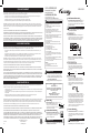 1
1
-
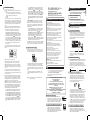 2
2
-
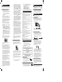 3
3
-
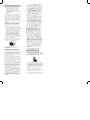 4
4


Malibu C Malibu 120 Watt Power Pack Manual de usuario
- Categoría
- Herramientas de jardín
- Tipo
- Manual de usuario
en otros idiomas
Otros documentos
-
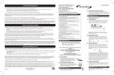 Malibu 8100-0900-01 Guía de instalación
-
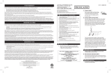 Proscapes 8111-0600-01 Guía de instalación
-
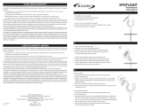 Malibu 8501-0604-01 Guía de instalación
-
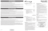 Malibu 8518-0104-08 Guía de instalación
-
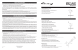 Malibu 8501-0610-02 Instrucciones de operación
-
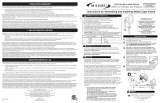 Malibu 8406-3550-01 Guía de instalación
-
Portfolio 8201080378 Guía de instalación
-
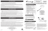 Malibu 8401-3500-01 Guía de instalación
-
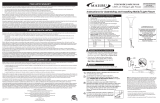 Malibu 8450-3101-01 Guía de instalación
-
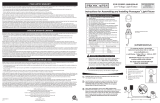 Proscapes 8608-0506-01 Guía de instalación


