Firman P06702 Manual de usuario
- Categoría
- Generadores de poder
- Tipo
- Manual de usuario

GASOLINE PORTABLE GENERATOR
P/N:367745451 Rev:00
Record product information to reference when ordering parts or
obtaining warranty coverage.
MODEL NUMBER
P06702
Rev Level:00
OPERATOR’S MANUAL

Table of Contents
English Customer Service: 1-844-FIRMAN1
. . . . . . . . . . . . . . . . . . . . . . . . . . . .1
Safety Precautions . . . . . . . . . . . . . . . . . . . . .2
Unpacking the Generator. . . . . . . . . . . . . . . .6
Parts Included. . . . . . . . . . . . . . . . . . . . . . . .6
Assembly . . . . . . . . . . . . . .. . . . . . . . . . . . . . . 7
Install the Wheel Kit . . . . . . . . . . . . . . . . . . 7
Install the Support Leg. . . . . . . . . . . . . . . . 7
Install the Handle. . . . . .. . . . . . . . . . . . . . . 7
Controls and Features. . . . . . . . . . . . . . . . . 8
Generator. . . . . . . . . . . . .. . . . . . . . . . . . . .8
Control Panel. . . . . . . . . . . . . . . . . . . . . . . 9
Specifications. . . . . . . . . . . . . . . . . . . . . . . . 11
Add Engine Oil . . . . . . . . . . . . . . . . . . . . . .12
Low Oil Shutdown . . . . . . . . . . . . . . . . . . .12
Add Fuel . . . . . . . . . . . . . . . . . . . . . . . . . . . 13
Operation at High Altitude . . . . . . . . . . .14
Grounding. . . . .. . . . . . . . . . . . . . . .. . . . . .14
System.. . . . . . . . . . . . . . . . . . . . . . .. . . . . .14
Operation . . . . . . . . . . . . . . . . . . . . . . . . .. . . . 15
Generator Location . . . . . . . . . . . . . . . . . . 15
Surge Protection . . . . . . . . . . . . .. . . . . . . .15
Starting the Generator . . . . . . . . . . . . . . . 16
Connecting Electrical Loads . . . . . . . .. . . 17
CO Alert . . . . . . . . . . . . . . . . . . . . . . . . . . . .17
Stopping the Engine . . . . . . . . . . . . . . . . . 17
Low Oil Shutdown . . . . . . . . . . . . . . . . . . 18
Do Not Overload Generator . . . . . . . . . . . 18
Introduction
Connecting to a Building’s Electrical
Maintenance And Storage. . . . . . . . . . . . . . 19
Maintenance Schedule . . . . . . . . . . . . . 19
Engine Maintenance .. . . . . . . . . . . .. . . . 20
Change Engine Oil . . .. . . . . . . . . . . . . . 20
Air Filter Maintenance. . . . . . . . . . . . . .20
Spark Plug Maintenance. . . . . . . . . . . . 21
Cleaning Fuel Strainer . . . . . . . . . . . . 21
. . . 21
Generator Maintenance . . . . . . . . . . . . . . 22
Service and Storage . . . . . . . . . . . . . . . .. 23
Trouble Shooting . . . . . . . . . . . . . . . . . . . . .24
Parts Diagram and Parts List . . . . . . . . . . 25
Generator Parts Diagram . . . . . . . . . . . . 25
Engine Parts Diagram . . . . . . . . . .. . . . . 26
Parts List . . . . . . . . . . . . . . . . . . . . . . . . . 27
Service Information . . . . . . . . . . . . . .. . . . . 30
Warranty. . . . . . . . . . . . . . . . . . . . . . . . . . . . . . .30
Inspect Muffler and Spark Arrester
Wiring Diagram. . . . . . . . . . . . . . . .. . . . . . .29

Thank you for purchasing a FIRMAN generator.
This manual covers operation and maintenance of the FIRMAN generators. All information in this
publication is based on the latest production information available at the time of approval for printing.
The manufacturer reserves the right to change, alter or other wise improve the generator and this
documentation at any time without prior change.
Page 01
This manual contains safety information to make you aware of the hazards and risks associated
with generator products and how to avoid them. This generator is designed and intended only
for supplying electrical power for operating compatible electrical lighting, appliances, tools and
motor loads, and is not intended for any other purpose. It is important that you read and
understand these instructions thoroughly before attempting to start or operate this equipment.
Save these original instructions for future reference.
Important Safety Information
The manufacturer cannot possibly anticipate every possible circumstance that might involve a
hazard. The warnings in this manual and the tags and decals affixed to the unit are therefore not
all-inclusive. If you use a procedure, work method or operating technique that the manufacturer
does not specifically recommend you must satisfy yourself that it is safe for you and others. You
must also make sure that the procedure work method or operating technique that you choose
does not render the generator unsafe.
Toxic Fumes
Fire Hazard
Hot Surface.
Do Not Touch the Surface.
Kickback
Risk of Electric Shock
Explosion Hazard
Rotating Parts Entanglement
Hazard
Operator’s Manual
INTRODUCTION
English Customer Service: 1-844-FIRMAN1
SAFETY INFORMATION
DANGER WARNING CAUTION
Indicates a hazard
which, if not avoided,
will result in death or
serious injury.
Indicates a hazard
which, if not avoided,
could result in death
or serious injury.
Indicates a hazard
which, if not avoided,
could result in minor or
moderate injury.

Page 02
English Customer Service: 1-844-FIRMAN1
SAFETY PRECAUTIONS
WARNING
POISONOUS GAS HAZARD.
•
•
•
•
•

Page 03
CORRECT USAGE
Example location to reduce risk of carbon monoxide poisoning
•ONLY use outside and downwind, far away from windows, doors and vents.
•Direct exhaust away from occupied spaces.
INCORRECT USAGE
Do not operate in any of the following locations:
Near any door, window or vent
Garage
Basement
Crawl Space
Living Area
Attic
Entry Way
Porch
Mudroom
English Customer Service: 1-844-FIRMAN1

Page 04
WHEN OPERATING EQUIPMENT
•
DO NOT tip engine or equipment at angle
which causes fuel to spill.
DO NOT stop engine by moving choke
control to “Start” position.
•
•
WHEN TRANSPORTING, MOVING
OR REPAIRING EQUIPMENT
Transport/move/repair with fuel tank
EMPTY or with fuel shutoff valve OFF.
•
•DO NOT tip engine or equipment at angle
which causes fuel to spill.
Disconnect spark plug wire.
•
WHEN STORING FUEL OR EQUIPMENT
WITH FUEL IN TANK
•
WARNING
•
•
WARNING
Generator voltage could cause
electrical shock or burn resulting
in death or serious injury.
•
WARNING
•
•NEVER start or stop engine with electrical
devices plugged in and turned on.
WARNING
Fuel and its vapors are extremely flammable
and explosive which could cause burns, fire,
or explosion resulting in death or serious
injury .
WHEN ADDING OR DRAINING FUEL
Turn generator engine OFF and let it cool at
least 2 minutes before removing fuel cap.
Loosen cap slowly to relieve pressure in tank.
Fill or drain fuel tank outdoors.
•
•DO NOT overfill tank. Allow space for fuel
expansion.
If fuel spills, wait until it evaporates before
starting engine.
•
Keep fuel away from sparks, open flames,
pilot lights, heat, and other ignition sources.
Check fuel lines, tank, cap, and fittings
frequently for cracks or leaks. Replace if
necessary.
DO NOT light a cigarette or smoke.
•
•
•
•
WHEN STARTING EQUIPMENT
Ensure spark plug, muffler, fuel cap, and air
cleaner are in place.
•
DO NOT crank engine with spark plug
removed.
•
Use approved transfer equipment, suitable
for the intended use, to prevent backfeed by
isolating generator from electric utility
workers.
English Customer Service: 1-844-FIRMAN1
Failure to use the appropriate U. S. Coast
Guard approved generator could result in
death or serious injury.

Page 05
WARNING
Unintentional sparking
could cause fire or
electric shock resulting
in death or serious
injury.
WHEN ADJUSTING OR MAKING REPAIRS TO
YOUR GENERATOR
Disconnect the spark plug wire from the
spark plug and place the wire where it cannot
contact spark plug.
•
WHEN TESTING FOR ENGINE SPARK
Use approved spark plug tester.
•DO NOT check for spark with spark plug
removed.
•
WARNING
NEVER operate generator without protective
housing or covers.
DO NOT wear loose clothing, jewelry or
anything that could be caught in the starter
or other rotating parts.
Tie up long hair and remove jewelry.
•
•
•
•
•
DO NOT exceed the generator’s wattage
amperage capacity.
Start generator and let engine stabilize
before connecting electrical loads.
•
•
•
•
CAUTION
Exceeding generators wattage/amperage capacity
could damage generator and/or electrical devices
connected to it.
Connect electrical loads in OFF position,
then turn ON for operation.
Turn electrical loads OFF and disconnect
from generator before stopping generator.
•
•
•
DO NOT use generator with electrical cords
which are worn, frayed, bare or otherwise
damaged.
DO NOT operate generator in the rain or
wet weather.
DO NOT handle generator or electrical
cords while standing in water, while
barefoot, or while hands or feet are wet.
DO NOT allow unqualified persons or
children to operate or service generator.
•
WARNING
Exhaust heat/gases could ignite combustibles,
structures or damage fuel tank causing a fire,
resulting in death or serious injury.
Contact with muffler area could cause burns
resulting in serious injury.
DO NOT touch hot parts and AVOID hot
exhaust gases.
Allow equipment to cool before touching.
It is a violation of California Public Resource
Code, Section 4442, to use or operate the
engine on any forest-covered, brush-covered,
or grass-covered land unless the exhaust
system is equipped with a spark arrester, as
defined in Section 4442, maintained in
effective working order. Other states or
federal jurisdictions may have similar laws.
Contact the original equipment manufacturer,
retailer, or dealer to obtain a spark arrester
designed for the exhaust system installed on
this engine.
Replacement parts must be the same and
installed in the same position as the original
parts.
•
•
•
•
When using generator for backup power,
notify utility company.
Use a ground fault circuit interrupter (GFCI)
in any damp or highly conductive area,
such as metal decking or steel work.
DO NOT touch bare wires or receptacles.
•
•
•
English Customer Service: 1-844-FIRMAN1
NOTICE

Page 06
•
•
•
•
•
Use generator only for intended uses.
If you have questions about intended use,
ask dealer or contact local service center.
Operate generator only on level surfaces.
DO NOT expose generator to excessive
moisture, dust, dirt, or corrosive vapors.
DO NOT insert any objects through cooling
slots.
If connected devices overheat, turn them off
and disconnect them from generator.
Shut off generator if:
-Electrical output is lost.
-Equipment sparks, smokes, or emits flames.
-Unit vibrates excessively.
•
•
WARNING
Medical and Life Support Uses.
In case of emergency, call 911 immediately.
NEVER use this product to power life support
devices or life support appliances.
NEVER use this product to power medical
devices or medical appliances.
Inform your electricity provider immediately
if you or anyone in your household depends
on electrical equipment to live.
Inform your electrical provider immediately
if a loss of power would cause you or anyone
in your household to experience a medical
emergency.
•
•
•
•
•
Improper treatment of generator could damage
it and shorten its life.
UNPACKING THE GENERATOR
•
•
Parts Included
Your gasoline powered generator ships with
the following parts:
1. Axle Pin . . .. . . . . . . . . . . . . . . . . . . . . . . . . . . . . .2
2. 10.0" in. Wheel . . . . . . . . . . . . . .. . . . . . . . . . . . . 2
3. Flat Washer. . . . . . . . . . . . . . . . . . . . . . . . . . . .2
4. Cotter Pin. . . . . . . . . . . . . . . . . .. . . . . . . . . . . . . .2
5. Engine Oil(Bottle) . . . . . . . . . . . . . . . . . . . . .1
6. Oil Funnel . . . . .. . . . . . . . . . . . . . . . . . . . . . . . . . 1
7. Wrench for Spark plug . . . . . . . . . . . . . . . . . . . .1
8. Double Open wrench (10mm & 12mm). . . . 2
9. Support Leg with Vibration Mounts . . . . . . 1
10. Flange Bolt (M8x16 for Support Leg) . . . . 2
11. Flange Lock Nut (M8) . . . . . . . . . . . . . . . . . . . 4
12. Handle . . . . . . . . . . . . . . . . . . . . . . . . . . . . .. . . . 1
13. Flange Bolt (M8x50 for Handle) . . . . . . . . . 2
14. Manual. . . . . . . . . . . . . . . . . . . . . . . . . . . 1
15. QSSG. . . . . . . . . . . . . . . . . . . . . . . . . . . . . . 1
16. Cover . . . . . . . . . . . . . . . . . . . . . . . . . . . . . . . . .1
1
4
56
7
QSSG
8
9
10
11
12
15
3
11 13
Manual
14
English Customer Service: 1-844-FIRMAN1
2
NOTICE
16

Page 07
Install the Wheel Kit
The wheel kit is not intended for over-the-road
use.
Install the Support Leg
ASSEMBLY Install the Handle
1. Place the handle K over the mounting channel
on the frame.
2. Secure the handle to the frame using the two
handle flange bolts H(M8x50).
3. Place a flange nut F (M8) on the end of each
bolt and fasten securely with provided
wrenches.
DO NOT over tighten the flange nuts.
F
The generator requires some assembly prior to
usage. If problems arise when assembling the
generator, call 1-844-347-6261.
F
E
G
H
K
1. Before adding wheels, tip the generator on
its side.
2. Slide the axle pin A through the wheel B.
3. Slide the axle pin A through the mount point
on the frame and flat washer D.
4. Secure the wheel and axle pin with the cotter
pin C.
5. Repeat steps 2-4 to attach another wheel.
1. Attach the support leg G to the generator
frame with flange bolts E (M8x16) and flange
lock nuts F(M8).
2. Tip the generator slowly so that it rests
on the wheels and support leg.
3.Tighten bolt E and nut F with provide
wrenches.
English Customer Service: 1-844-FIRMAN1
A
B
CD
NOTICE

Page 08
CONTROLS AND FEATURES
Generator
1- Fuel Gauge
2- 8.0 Gallon(30L) Capacity Fuel Tank
3- Fuel Cap
4- Choke Lever
5- Fuel Valve
6- Air Filter
7- 389cc FIRMAN OHV Engine
8- Recoil Starter
9- 10.0"(25cm) Flat Free Wheel
10- Oil Filler Cap
11- Outlet Cover
12- Control Panel
13- Handle
14- Data Decal/Serial Number
*We are always working to improve our products. Therefore, the enclosed product may differ
slightly from the image on this page.
English Customer Service: 1-844-FIRMAN1
⑦
⑧⑨⑩
⑪
⑫
⑬
1
2①
②
③
④
⑤
⑥
⑭

Page 09
English Customer Service: 1-844-FIRMAN1
Control Panel
1
24-1 Data-Minder(Multi-Meter) – Push the
SELECT button to show the Voltage, Hertz and
running hours. If the low oil indicator is lit,
check the oil level.
3
4
5
7
120V, 30A Twist Lock (NEMA L5-30R)
6
Total power drawn from all receptacles must not exceed the data decal rating.
8
Outlet Cover - Protect the receptacles from
dust and debris.
A - Digital display
B - AC voltage indicator
C - Frequency indicator
D - Hour indicator
E - Low oil indicator
F - Select button
1
23456
7
8
Ground Terminal – Consult an electrician
for local grounding regulations.
120/240V, 30A Twist Lock – (NEMA L14-30R)
Ground Fault Circuit Interrupter conforms to
UL 943 and NEC requirements. This device
protects you against hazardous electrical shock
that may be caused if your body becomes a
path through which electricity travels to reach
ground. This could happen when you touch an
appliance or cord that is “ live “ through faulty
mechanism, damp or worn insulation, etc.
120V, 20A Duplex GFCI (Ground Fault
Circuit Interrupter) – (NEMA 5-20R)
This receptacle is rated so that a total of 20
Amp may be drawn regardless of whether
both halves or just one receptacle is used.
Engine Switch – Flip the switch to the “ON(l)”
position and pull the recoil starter to start the
generator. Turn to the “OFF(O)” position to
turn off the generator.
NOTICE
Maximum 30 Amp current may be drawn
from this 120 Volt receptacle.
Maximum 27.9 Amp current maybe drawn
from this 120/240 Volt receptacle.
9
CO Alert™ Carbon Monoxide (CO) Shutdown
Indicator Light — Indicates the engine shut
down due to carbon monoxide accumulation
around the generator or a CO Alert system
fault occurred.
9

Page 10
English Customer Service: 1-844-FIRMAN1
120VAC, 20AMP GFCI RECEPTACLE
This unit is equipped with a ground fault circuit
interrupter (GFCI). This device meets applicable
federal, state and local codes .
A GFCI receptacle does NOT protect against
circuit overloads, short circuits, or shocks. For
example, electric shock can still occur if a person
touches charged electrical wires while standing
on a non-conducting surface, such as a wood floor.
Definition: Instead of following its normal safe
path, electricity passes through a persons body
to reach the ground. For example, a defective
appliance can cause a ground fault.
A GFCI receptacle is different from conventional
receptacles. In the event of a ground fault, a GFCI
will trip and quickly stop the flow of electricity to
prevent serious injury.
1. Plug a test lamp into the receptacle.
2. Start the generator, the test lamp should be on.
3. Press the “Test” button located on the front
of the receptacle to trip the device.
4. This should stop the flow of electricity making
the lamp shut off. The GFCI’s indicator light comes
off.
RESET
TEST
TEST MONTHLY
FOLLOW DIRECTIONS
RESET BUTTON
Receptacle
Outlet
LED Indicator Light
TEST BUTTON
Outlet
5. To restore the flow of electricity, press the
“RESET” button on the front of the receptacle.
If the GFCI does not perform in this manner, do
not use the receptacle. Contact a local service
dealer or costumer service.
6. This outlet is protected against overload by
a 20A push-to-reset circuit breaker. Use the
outlet to power 120V AC, single-phase, 60 Hz,
electrical loads requiring up to a combined
2400 watts (2.4 kW) or 20 amps of current.
Testing the GFCI: Test the GFCI outlet every
month as follows:
SELF-TEST OPERATION
A Self-Test GFCI receptacle has all the features
of a conventional GFCI receptacle. In addition,
this receptacle tests itself periodically to confirm
the GFCI electronics are functional. The Indicator
Light will be solid green when the GFCI is powered
from Line side and working correctly.
Self-Test Indications: If the Indicator Light is solid
orange or flashing red a problem may exist.
Press the TEST button to trip the GFCI. If unable to
Reset, replace the GFCI.

Page 11
SPECIFICATIONS
English Customer Service: 1-844-FIRMAN1
Model
Rated AC Voltage
Phase
Power Factor
Voltage Regulator
Alternator Type
Running Watts*
Starting Watts
Engine
Engine Type
Displacement
Low Oil Shutdown
Ignition System
Starting System
Fuel
Capacity Fuel Tank
Lubricating Oil Capacity
Carburetor Type
Air Cleaner
P.T.O. Shaft Rotation
120/240V
P06702
6700
AVR
Single
1
Single Cylinder, 4-Stroke OHV Air Cooled
389cc
Breakless Ignition Type, Flywheel Magneto
Unleaded Automotive Gasoline
Recoil
8.0 Gallon (30L)
37.2 oz(1.1L)
Counter Clockwise (Facing P.T.O.)
Float
Brushed
Polyurethane Type
Yes
8375
FIRMAN
Rated Fequency 60Hz
Oil Type
See “Add Engine Oil” Section
Total Harmonic Distortion(THD) Standard
AC Grounding System
Neutral Bonded To Frame
* Generator complies with PGMA (Portable Generator Manufacturers’Association) standard
ANSI/PGMA G300-2018, Safety and Performance of Portable Generators.
AN IMPORTANT MESSAGE ABOUT TEMPERATURE:
Your FIRMAN generator has an operating temperature range of 5°F (-15°C) to 104°F (40°C). When
operated above 73°F (23°C) there may be a decrease in power. Rated wattage is subject to, and
limited by, such factors as fuel BTU content, altitude, ambient temperature, engine conditions, etc.
Rated wattage decrease about 1% for each 10°F(6°C) above 73°F(23°C). The generator may be
operated at temperatures ranging from 5°F(-15°C) to 122°F(50°C). If the generator is exposed to
temperatures outside this range during storage, the generator should be brought back within this
range before operation.

Add Engine Oil
Page 12
1.Place generator on a flat, level surface.
2.Clean area around oil fill and remove yellow
oil fill cap/dipstick.
3.Wipe dipstick clean.
The engine is equipped with a low oil shut-off and
will stop when the oil level in the crankcase falls
below the threshold level.
The unit is equipped with a low oil shutdown.If
the oil level becomes lower than required,the
sensor will activate a warning device or stop the
engine.
If generator shuts off and the oil level is within
specifications, check to see if generator is sitting
at an angle that forces oil to shift. Place on an
even surface to correct this. If engine fails to
start, the oil level may not be sufficient to
deactivate low oil level switch. Make sure the
sump is completely full of oil.
(H)
DRAIN PLUG
(L)
5.Replace oil fill cap/dipstick and fully tighten.
6.Oil level should be checked prior to each use
or at least every 8 hours of operation. Keep oil
level maintained.
4.Using oil funnel, slowly pour contents of
provided oil bottle into oil fill opening to the
"H" mark on dipstick. Be careful do not
overfill. Overfilling with oil could cause the
engine to not start or hard starting.
H
LLow Oil Shutdown
Degrees Celsiusº(Outside)
Full Synthetic 5W-30
Degrees Fahrenheitº(Outside)
5W-30 10W-40
10W-30
English Customer Service: 1-844-FIRMAN1
NOTICE
We recommend using FIRMAN SAE 10W-30 API
SJ oil for best performance. Other high-quality
detergent oils (API SJ or higher) are acceptable.
Do not use special additives. Ambient temperature
determines the proper oil viscosity for the engine.
Use the chart to select the proper oil for the
outdoor temperature range expected.
Do not attempt to crank or start the engine before
it has been properly filled with the recommended
type and amount of oil. Damage due to operation
with no oil will void your warranty.

Add Fuel
Page 13
Fuel must meet these requirements:
•Clean, fresh, unleaded gasoline.
Use regular UNLEADED gasoline with the
generator engine with a minimum 87 octane
/ 87 AKI (91 RON).
For high altitude use, see "Operation at High
Altitude".
Do not use gasoline with more than 10%
ethanol such as E85 or ethanol.
•
•
Failure to follow Operator's Manual for fuel
recommendations voids warranty.
Avoid generator damage.
DO NOT use unapproved gasoline such as E85.
DO NOT mix oil in gasoline.
DO NOT modify engine to run on alternate fuels.
•
•
•
WARNING
Fuel and its vapors are extremely flammable
and explosive which could cause burns, fire or
explosion resulting in death or serious injury .
WHEN ADDING FUEL
Fill fuel tank outdoors.
DO NOT overfill tank. Allow space for fuel
expansion. If the tank is overfilled, fuel
can overflow onto a hot engine and cause fire
or explosion.
If fuel spills, wait until it evaporates before
starting engine.
Keep fuel away from sparks, open flames,
pilot lights, heat, and other ignition sources.
Check fuel lines, tank, cap and fittings
frequently for cracks or leaks. Replace if
necessary.
DO NOT light a cigarette or smoke when
filling the fuel tank.
•
•
•
•
1.Clean area around fuel fill cap, remove cap.
2.Slowly add unleaded fuel to fuel tank. Be
careful not to fill above the red fuel level
indicator . This allows adequate space for
fuel expansion.
3.Install fuel cap and let any spilled fuel
evaporate before starting engine .
CAUTION
Slowly add unleaded gasoline to fuel tank.
Do not overfill tank.
Do not fill above top of fuel screen. This
will all expansion in hot weather and
prevent overflow.
•
•
•
English Customer Service: 1-844-FIRMAN1
NOTICE
deposits from forming in fuel system parts such
as the carburetor, fuel hose or tank during
storage. Alcohol-blended fuels (called gasohol,
ethanol or methanol) can attract moisture, which
leads to separation and formation of acids during
storage. Acidic gas can damage the fuel system
of an engine while in storage. To avoid engine
problems, the fuel system should be emptied
before storage of 30 days or longer. See the
" Long Term Storage" section. Never use engine
or carburetor cleaner products in the fuel tank
as permanent damage may occur.
It is important to prevent gum
NOTICE
Red Line Indicator

Page 14
English Customer Service: 1-844-FIRMAN1
389cc
357717002
357717003
Altitude main jet 1
Altitude main jet 2
Altitude
3000-6000Feet
6000-8000Feet
OPEN
Operation at High Altitude
At altitudes over 5,000 feet(1524 meters), a
minimum 85 octane gasoline is acceptable.
Engine power and generator output will be
reduced approximately 3.5% for every 1000
feet (305 m) of elevation above sea level. High
altitude may cause hard starting, increased fuel
consumption and spark plug fouling. To operate
at high altitudes FIRMAN can provide a high
altitude carburetor main jet. The alternative
main jet and installation instructions can be
obtained by contacting Customer Support.
NOTICE Operation using an alternative main
jet at elevations lower than the recommended
minimum altitude can damage the engine. For
operation at lower elevations, the standard
main jet supplied must be used. Operating the
engine with the wrong main jet may increase
exhaust emissions, fuel consumption and
reduce performance.
(914-1828 m)
(1828- 2438 m)
Grounding
The generator has a system ground that connects
the generator frame components to the ground
terminals on the AC output receptacles. The
system ground is connected to the AC neutral
wire. The neutral is bonded to the generator
frame. There may be Federal or State regulations,
local codes, or ordinances that apply to the
intended use of the generator. Consult a qualified
electrician, electrical inspector, or the local
agency having jurisdiction. This generator is not
intended to be used at a construction site or
similar activity as defined by NFPA 70-2020 (NEC)
section 590.6.
Use approved transfer equipment to prevent
backfeed by isolating generator from electric
utility workers.
When using generator for backup power, notify
utility company.
Use a ground fault circuit interrupter (GFCI) in
any damp or highly conductive area, such as
metal decking or steel work.
DO NOT touch bare wires or receptacles.
DO NOT use generator with electrical cords
which are worn,frayed, bare or otherwise
damaged.
DO NOT operate generator in the rain or wet
weather.
DO NOT handle generator or electrical cords
while standing in water, while barefoot, or
while hands or feet are wet.
DO NOT allow unqualified persons or children
to operate or service generator.
Connecting to a Building's Electrical System
WARNING
Generator voltage could cause
electrical shock or burn resulting
in death or serious injury.
•
•
•
•
•
•
•
•
Connections to your home’s electrical system
must use a listed transfer switch installed by
a licensed electrician. The connection must
isolate the generator power from the utility
power and comply with all applicable laws and
electrical codes.

OPERATION
Page 15
Generator Location
Make sure you review each warning in order to
prevent fire hazard.
Keep area clear of inflammables or other
hazardous materials.
Select a site that is dry, well ventilated and
protected from the weather.
Keep exhaust pipe clear of foreign objects.
Keep generator away from open flame.
Keep generator on a stable and level surface.
WARNING
Surge Protection
Voltage fluctuation may impair the proper
functioning of sensitive electronic equipment.
POISONOUS GAS HAZARD.
•
•
•
•
Do not block generator air vents with paper or
other material.
Tilting can cause fuel spillage.
English Customer Service: 1-844-FIRMAN1
NOTICE
NOTICE

Page 16
Starting the Generator
1. Before starting the generator, check for loose
or missing parts and for any damage which
may have occurred during shipment.
2. Check oil level and fuel.
6. Move the choke lever to the “START” position.
5. Flip the engine switch to the “ON”(l) position.
8. Do not over-choke. As soon as engine starts
and warms up, move the choke lever to the
“RUN” position.
9. Allow generator to run at no load for few
minutes upon each initial start-up to permit
engine and generator to stablize.
WARNING
When starting engine, pull cord slowly until
resistance is felt and then pull rapidly to avoid
kickback.
4. Turn the fuel valve to the “ON” (l)position.
7. Pull the starter cord slowly until resistance is
felt and then pull rapidly.
3. Disconnect all electrical loads from the
generator. Never start or stop the generator
with electrical devices plugged in or turned
on.
English Customer Service: 1-844-FIRMAN1
Keep choke lever in “START” position for only 1
pull of the recoil starter. After first pull, move
choke lever to the “RUN” position for up to the
next 3 pulls of the recoil starter. Too much choke
leads to sparkplug fouling/engine flooding due
to the lack of incoming air. This will cause the
engine not to start.
NOTICE
NOTICE

Page 17
Connecting Electrical Loads
1.Let engine stabilize and warm up for a few
minutes after starting.
2.Ensure circuit breaker on control panel is in
on position.
3.Plug in and turn on the desired 120 or 240 Volt
AC, single phase, 60Hz electrical loads. It is
better to attach the item with largest load first.
Stopping the Engine
1. Turn off and remove entire electrical loads.
Never start or stop the generator with
electrical devices plugged in or turned on.
This unit has been pretested and adjusted to
handle its full capacity. Before starting the
generator, disconnect all load. Apply load only
after generator is running. Voltage is regulated
via the engine speed adjusted at the factory for
correct output. Readjusting will void warranty.
When applying a load, do not exceed the maximum
wattage rating of the generator when using one or
more receptacles. Also, do not exceed the amperage
rating of any one receptacle.
Do not apply heavy electrical load during break-in
period (the first five hours of operations).
Let the generator run at no-load for two
minutes to stabilize internal temperatures
of the engine and generator.
English Customer Service: 1-844-FIRMAN1
NOTICE
CO Alert automatically shuts down the engine
when harmful levels of carbon monoxide
accumulate around the generator or a CO Alert
fault occurs. After shutdown, the CO Alert
indicator light will blink for at least five minutes
per the chart below.
Color Description
Red
Yellow CO Alert fault occured*.
See FIRMAN authorized service dealer.
*Yellow light will blink for five seconds at the
startup of generator to show CO ALERT is
functioning properly.
TM
Carbon monoxide accumulated
around generator. Prior to restart
move generator to an open, outdoor
area 20 ft. (6 m) from occupied
spaces with exhaust pointed away.
Air out premises (open windows
and doors) before reoccupying
property. Automatic shutoff is an
indication generator was improperly
located.
If you start to feel sick, dizzy, weak,
or your homes carbon monoxide
alarm sounds while using this
product, get to fresh air right away.
Call emergency services. You may
have carbon monoxide poisoning.
•• ••
•••• •
CO Alert
Carbon Monoxide (CO) Shutdown System
CO Alert DOES NOT replace carbon monoxide
alarms.
Install battery-powered carbon monoxide
alarm(s) in your home. Don’t run generator in
enclosed areas.

Page 18
Do Not Overload Generator
If the engine will not be used for a period of two
weeks or longer, please see the Storage section
for proper engine and fuel storage.
Low Oil Shutdown
If the engine oil drops below a preset level, an
oil switch will stop the engine. Check oil level
with dipstick.
If oil level is between LOW and HIGH mark on
dipstick:
1.DO NOT try to restart the engine.
2.Contact an Authorized FIRMAN Service Dealer.
3.DO NOT operate engine until oil level is
corrected.
If oil level is below LOW mark on dipstick:
1.Add oil to bring level to HIGH mark.
2.Restart engine and if the engine stops again
a low oil condition may still exist. DO NOT try
to restart the engine.
3.Contact an Authorized FIRMAN Service Dealer.
4.DO NOT operate engine until oil level is
corrected.
Overloading a generator in excess of its rated
wattage capacity can result in damage to the
generator and to connected electrical devices.
To prolong the life of your generator and
attached devices, follow these steps to add
electrical load:
1. Start the generator with no electrical load
attached.
2. Allow the engine to run for several minutes
to stabilize.
3. Plug in and turn on the first item. It is best to
attach the item with the largest load first.
4. Allow the engine to stabilize.
5. Plug in and turn on the next item.
6. Allow the engine to stabilize.
7. Repeat steps 5-6 for each additional item.
English Customer Service: 1-844-FIRMAN1
NOTICE
WARNING
If a cover is used, do not install until unit has cooled.
Fuel and its vapors are extremely flammable and
explosive which could cause burns, fire or
explosion resulting in death or serious injury.
2. Press the engine switch to the “OFF”(O) position.
3. Turn the fuel valve to the “OFF”(O) position.
Do not leave the generator until it has
completely stopped.
DO NOT stop engine by moving choke control
to “START” position.
NOTICE Always ensure that the
is in the “OFF” position when the engine
is not in use.
fuel selector
switch

Page 19
English Customer Service: 1-844-FIRMAN1
MAINTENANCE AND STORAGE
MAINTENANCE SCHEDULE
General Recommendations
Regular maintenance will improve the performance and extend the life of the generator. See any
authorized dealer for service.
The generator's warranty does not cover items that have been subjected to operator abuse or
negligence. To receive full value from the warranty, the operator must maintain the generator as
instructed in this manual.
Some adjustments will need to be made periodically to properly maintain your generator.
All service and adjustments should be made at least once each season. Follow the requirements
in the Maintenanc Shedule chart above.
NOTICE Once a year you should clean or replace the spark plug and replace the air filter. New
spark plug and clean air filter assure proper fuel-air mixture and help your engine run better
and last longer.
ITEM NOTES Daily(Before
operation)
Initial
25 hours
Every
50 hours
Every
100 hours
(or annual)
Fittings/
Fasteners
Spark Plug
Engine Oil
Air Filter
Fuel Line
Exhaust
System
Engine
Check condition. Adjust gap
and clean. Replace if necessary.
Check oil level.
Clean, replace if necessary.
Check for leakage. Retighten or
replace gasket if necessary.
Check adjust valve clearance.
Clean combustion chamber.
Check. Replace if necessary.
Check fuel hose for cracks or other
damage. Replace if necessary.
√
√
√
√
√
√
√
√
√
√
Replace.
Check spark arrester screen.
Clean/Replace if necessary.
Every
250 hours
√
To be performed by knowledgable/experienced owner or by authorized service center.
*
*
*
Fuel Filter Clean fuel filter and fuel tank
strainer. Replace if necessary. √

ENGINE MAINTENANCE
Air Filter Maintenance
Use fresh and high quality lubricating oil to the
specified quantity.
If contaminated or deteriorated oil is used or
the quantity of the engine oil is not sufficient,
engine damage will result and its life will be
greatly shortened.
Page 20
Change Engine Oil
To prevent accidental starting, remove and
ground spark plug wire before performing any
service.
If you are using your generator under extremely
dirty or dusty conditions, or in extremely hot
weather, change the oil more often.
Avoid prolonged or repeated skin contact with
used motor oil.
CAUTION
Used motor oil has been shown to cause skin
cancer in certain laboratory animals.
Thoroughly wash exposed areas with soap
and water.
•
•
•
(a) Drain oil by removing the drain plug and the
oil filler cap while the engine is warm.
Change engine oil every 100 hours.
(for a new engine, change oil after 25 hours.)
DRAIN PLUG
Please use a container to dispose of the oil at an
approved recycling center.
(b) Reinstall the drain plug and fill the engine
with oil until it reaches the HIGH(H) level on the
oil filler cap.
Maintaining an air filter in proper condition is
very important. Dirt induced through improperly
installed, improperly serviced, or inadequate
elements damages and wears out engines.
Always keep the element clean.
(a) Take out the air cleaner, clean it well in
kerosene and dry it.
(b) After wetting the element with clean engine
oil squeeze it tight by hand.
(c)Lastly, put the element in the case and install
it securely.
English Customer Service: 1-844-FIRMAN1
NOTICE

Page 21
Spark Plug Maintenance
Changing the spark plug will help your engine
to start easier and run better.
(a) Remove the spark plug cap.
(d) Adjust the electrode gap to
(0.7 to 0.8 mm).
0.028” to 0.031”
(e) Seat spark plug in position and thread by
hand to prevent cross threading.
(f) Tighten plug with provided wrench and put
the cap back on spark plug.
SPARK PLUG: TORCH F6RTC
NGK BPR6ES
CHAMPION RN9YC or equivalent.
Cleaning Fuel Strainer
Dirt and water in the fuel are removed by the fuel
strainer.
(a) Remove the strainer cup and throw away water
and dirt.
(b) Clean the screens and strainer cup with gasoline.
(c) Tightly fasten the cup to main body,
making sure to avoid fuel leak.
SCREEN
O-ring
CUP
BODY
(b) Remove spark plug using provided wrench.
Inspect spark plug for damage and clean
with a wire brush before reinstalling
Inspect Muffler and Spark Arrester
Inspect the muffler for cracks, corrosion, or
other damage. Remove the spark arrester, if
equipped, and inspect for damage or carbon
blockage. If replacement parts are required,
make sure to use only original equipment
replacement parts.
Exhaust heat/gases could ignite combustibles,
structures or damage fuel tank causing a fire,
resulting in death or serious injury and/or
property. Contact with muffler area could cause
burns resulting in serious injury.
WARNING
A
B
A- Spark plug
B- Spark plug cap
c) (
English Customer Service: 1-844-FIRMAN1
Maintenance Valve Clearance
- Intake: ( )
- Exhaust: 0.004 - 0.006 in. (0.1 - 0.15 mm)
0.004 - 0.006 in. 0.1 - 0.15 mm
0.028-0.031 in
(0.7-0.8 mm)

Page 22
DO NOT touch hot parts and AVOID hot exhaust
gases.
Allow equipment to cool before touching.
Keep at least 5 feet (1.5 m) of clearance on all
sides of generator including overhead.
Replacement parts must be the same and
installed in the same position as the original
parts.
Clean or replace spark arrester as follows:
1. Allow the engine to cool completely before
servicing the spark arrester.
2. Remove the screws securing the spark arrester
in place and the remove it from muffler.
3. Carefully remove the carbon deposits from
the spark arrester screen with a wire brush.
Failure to clean the spark arrester will result in
degraded engine performance.
Generator Maintenance
Make certain that the generator is kept clean
and stored properly. Only operate the unit on
a flat, level surface in a clean, dry operating
environment. DO NOT expose the unit to
extreme conditions, excessive dust, dirt,
moisture or corrosive vapours.
DO NOT use a garden hose to clean the generator.
Water can enter the generator through the cooling
slots and damage the generator windings.
Use a damp cloth to clean exterior surfaces of
the generator.
Use a soft bristle brush to remove dirt and oil.
Use an air compressor 25 PSI (172 kPa) to clear
dirt and debris from the generator.
Inspect all air vents and cooling slots to ensure
that they are clean and unobstructed.
•
•
•
•
Depending on the type fuel used ,the type and
amount of lubricant used, and/or your operating
conditions, the exhaust part and muffler may
become blocked with carbon deposits. If you
notice power loss, you may need to remove these
deposits to restore performance.
4. Replace the spark arrester if it is damaged.
5. Position the spark arrester in the muffler and
attach with the screws.
Spark arrester
screen
Flange
Screw
English Customer Service: 1-844-FIRMAN1
NOTICE

Page 23
English Customer Service: 1-844-FIRMAN1
SERVICE AND STORAGE
Any damages or hazards caused by using
improper fuel, improperly stored fuel, and/
or improperly formulated stabilizers, are not
covered by manufacturer's warranty.
Infrequent Service
If the unit is used infrequently, difficult starting
may result. To eliminate hard starting, follow
these instructions:
1. Run the generator at least 30 minutes every
month.
2. Run the generator, then close the fuel shut-off
valve and allow the unit to run until the engine
stops.
3. Move the engine switch to the "OFF" position.
Long Term Storage
It is important to prevent gum deposits from forming
in essential fuel system parts such as the carburetor,
fuel hoses or tank during storage. Also, experience
indicates that alcohol-blended fuels (called gasohol,
ethanol or methanol) can attract moisture, which leads
to separation and formation of acids during storage.
Acidic gas can damage the fuel system of an engine
while in storage.
When the generator set is not being operated, or
is being stored for more than one month, follow
these instructions to avoid engine problems:
•
1-ADD a properly formulated commercially FUEL
STABILIZER to the tank if it is not already added.
2-Operate the engine for 5-10 minutes to circulate
treated fuel into fuel lines and carburetor before
3- After engine cools down, remove all gasoline
from the fuel tank. Use a commercially available,
non-conductive vacuum siphon.
shutdown.
Drain fuel into approved container outdoors,
away from open flame. Be sure engine is cool.
Do not smoke.
4-FUEL STARVATION: Start and run the generator
until it stops from lack of fuel. This will dry out all
remaining fuel in tank, fuel lines and carburetor.
7-Remove spark plug and pour about one teaspoon
of engine oil through the spark plug hole, then pull
the recoil starter several times to distribute the oil for
lubricating the cylinder. Reattach the spark plug.
Pull recoil slowly until resistance is felt. This will
close the valves so moisture cannot enter engine
cylinder. Gently release recoil starter.
5-Allow the unit to cool entirely before cleaning
and storage.
6-Change oil with recommended grade oil.
8-Keep the engine switch and fuel valve on “OFF”
position.
9-Cover the unit and store in a clean, dry place
out of direct sunlight. NEVER USE WATER TO
CLEAN GENERATOR.
We recommend always using a fuel stabilizer.
A FUEL STABLIZER will minimize the formula-
tion of fuel gum deposits during storage, the
fuel stabilizer can be added to the gasoline in
the fuel tank, or into the gasoline in a storage
container.
•If it is not practical to empty the fuel tank and
the unit is to be stored for some time, use a
commercially available FUEL STABILIZER added
to the gasoline to increase the life of the gasoline.
Run the unit for 5-10 minutes, turn off the fuel
valve and allow to run until engine stops from
lack of fuel (FUEL STARVATION).
•
Do not store gasoline from one season to
another season.
•
WARNING
NOTICE

TROUBLE SHOOTING
Page 24
Problem Cause Correction
Engine is running, but no
AC output is available.
1. Circuit breaker is open.
2. Fault in generator.
3. Poor connection or defective cord
set.
4. Connected device is bad.
1. Reset circuit breaker.
2. Contact authorized service facility.
3. Check and repair.
4. Connect another device that is in
good condition.
Engine runs good at
no-load but “bogs down”
when loads are connected.
1. Short circuit in a connected load.
2. Engine speed is too slow.
3. Generator is overloaded.
4. Shorted generator circuit.
1. Disconnect shorted electrical load.
2. Contact authorized service facility.
3. See Don't Overload Generator
4. Contact authorized service facility.
Engine will not start; starts
and runs rough or shuts
down when running.
1. Engine switch set to OFF (O)
position.
2. Fuel shutoff lever is in OFF (O)
position.
3. Low oil level.
4. Dirty air cleaner.
5. Out of fuel.
6. Stale fuel.
7. Spark plug wire not connected to
spark plug.
8. Bad spark plug.
9. Water in fuel.
10. Flooded.
11. Excessively rich fuel mixture.
12. Intake valve stuck open or closed.
13. Engine has lost compression.
1. Set engine switch to ON (l)
position.
2. Move fuel shutoff lever to ON (l)
position.
3. Fill crankcase to proper level or
place generator on level surface.
4. Clean or replace air cleaner.
5. Fill fuel tank.
6. Drain fuel tank and carburetor; fill
with fresh fuel.
7. Connect wire to spark plug.
8. Replace spark plug.
9. Drain gas tank and carburetor; fill
with fresh fuel.
10. Wait 5 minutes and re-crank engine.
11. Contact authorized service facility.
12. Contact authorized service facility.
13. Contact authorized service facility.
Engine lacks power.
1. Load is too high.
2. Dirty air filter.
1. Don't Overload Generator
2. Replace air filter.
Engine“hunts”or falters.
1. Carburetor is running too rich or too lean.1. Contact authorized service facility.
14. Clogged or dirty fuel filter.
5. Clean or replace fuel filter.
14. Clean or replace fuel filter.
3. Clogged or dirty fuel filter.
4. Clogged spark arrester.
3. Clean or replace fuel filter.
4. Clean or replace spark arrester.
2. Clogged or dirty fuel filter. 2. Clean or replace fuel filter.
Engine shuts down when
running.
1. Out of fuel.
2. Dirty air cleaner.
3. Low oil level.
1. Fill fuel tank.
2. Clean or replace air cleaner.
3. Fill crankcase to proper level or place.
generator on level surface.
5. Clogged or dirty fuel filter.
English Customer Service: 1-844-FIRMAN1
Engine shuts down and yellow
CO fault lightblinking.
1. CO system fault 1. Contact authorized FIRMAN service
facility.

Page 25
PARTS DIAGRAM AND PARTS LIST
P06702 PARTS DIAGRAM
English Customer Service: 1-844-FIRMAN1

Page 26
English Customer Service: 1-844-FIRMAN1
FIRMAN 389cc Engine Parts Diagram

Page 27
P06702 Parts List
NO. Part Number Description Qty.
English Customer Service: 1-844-FIRMAN1
NO. Part Number Description Qty.
1
2
3
4
5
6
6.1
6.2
6.3
7
8
9
10
11
12
13
14
15
16
17
18
19
20
21
22
23
24
25
26
27
28
29
30
31
32
33
34
35
36
37
38
39
40
41
42
42.1
42.2
42.3
42.4
42.5
43
44
45
46
47
48
49
50
50.1
50.2
50.3
50.4
51
52
52.1
52.2
52.3
52.4
53
54
55
56
57
58
59
60
61
62
63
64
64.1
64.2
64.3
64.4
65
66
67
68
69
70
71
72
73
74
75
76
77
78
79
80
81
81.1
82
82.1
83
84
85
86
87
88
89
90
91
92
93
94
95
96
97
98
367718301
357713501
357713524
336713528
357713573
367418300
367418301
367418302
357713505
357713506
357713507
336713525
357713563
367718300
336713519
336713523
336713520
357713599
336713519
357713509
336713507
336713511
336713577
357713510
357713512
336718301
336713517
336713516
357713601
336713533
336713509
357713520
357713521
357713523
357713515
336713531
336718302
357713516
336713538
357713517
336713536
357713518
336713534
357713527
357413505
336713590
336713591
357713526
336713594
357713522
336713558
357713519
357713535
357713514
357713536
357713534
336713559
357413506
336723555
357713538
336713557
336713561
336713558
357713528
336713548
357713528
336713542
357713600
336713549
357713529
336713547
336713546
393713018
336713540
357713525
357713548
380713510
336713551
357713531
357713562
357713532
357713533
336718318
357718300
336718306
336755004
336755005
336755002
336713573
357713541
357713542
357713543
336713512
336713513
336713516
367418303
336718302
357713547
336713832
336713601
330713594
336713569
367718300
336713569
336713568
357713539
329713608
336713589
336713570
336713567
357713565
336713565
336713569
336755000
330713518
336713565
336713564
357713545
357713546
357713548
Engine Subassembly
Rubber Cap B
Build Up,fore-cover A
Flange. Bolt M6×8
Generator Wind Shield
Alternator Assy
Rotor Comp
Stator Assy
Stator Cover
Generator End Cover
Carbon Brush Assembly
Carbon Brush Holder
Bolt &washer Assemblies
AVR
Flange. Bolt M5×16
Terminal Block
Bolt &washer Assemblies
Neutral Wire
Flange. Bolt M5×16
Generator End Cover Cap
Flange. Bolt M5×12
Flange Bolt M6×179
Nut M5
Side Cover Bolt M5×214
Flange Bolt M10×265
Flange. Bolt M6×12
Nut M6
Ground Wire
Flat Washer Ø8
Spring Washer Ø8
Gskt.,ext.
Muff.,assy.
Guard,muff.,back
Bracket,muff
Flange. Bolt M8×20
Flange. Bolt M6×12
Protector, Muff.,side
Screw&washer Assy M5×14
Holder,spark Arrester
Arrester,spark
Protector,muff.,front
Nut M8
Flange. Bolt M8×50
Handle Assembly
Pin, Shaft
Flat Washer ( 8.2×ø17×0.8)
Bracket, Handle
Pin, Handle
Handle
Nut M8
Cover, Handle
Axle Pin
Flat Washer Ø10
Cotter Pin
Wheel
Flange. Bolt M8×16
Support Leg Assembly
Nut M6
Support Leg
ø
Rubber, Support
Flange. Bolt M6×25
Nut M8
Fuel Tank Assy
Fuel Filter, Wire Mesh
Fuel Tank
Grommet, Fuel Tank
Bushing
Fuel Tank Cap Comp.
Fuel Gauge Assy.
Fuel Gauge Display
Screw M5×10
Bolt M6×20
Clamp Ø8×6
Formed Vapor Hose
Clamp
Hose,fuel
Fuel Valve
Nut M10
Frame Assy
Isolator Ii
Isolator I
Nut M8
Frame
Engine Switch
Engine Switch Cover
Circuit Breaker Cover
Indicator Light
Outlet Cover L5-30R
Outlet Cover 5-20R GFCI
Flange. Bolt M6×22
Nut M6
Lock Washer Ø6
Flat Washer Ø6
Control Panel
Flange. Bolt M6×12
Receptacle GFCI
Receptacle L5-30R
Receptacle L14-30R
Circuit Breaker Amp20A
Screw&washer Assy M4×8
Circuit Breaker Amp 28A
Screw&washer Assy M4×8
Nut M4
Control Box
Flat Washers
Screw&washer Assy M5×38
Multi Meter
Nut M3
Diode Module
Screw M5×14
Screw&washer Assy M4×8
Co Module
Screw&washer Assy M5×14
Screw M5×14
Grommet
Grommet
Sleeve
Grommet
External Teeth Lock Washer Ø6
External Teeth Lock Washer Ø6
1
1
1
1
1
1
1
1
1
1
1
1
1
1
2
1
2
1
1
1
2
4
2
2
1
1
1
1
1
2
2
1
1
1
1
4
7
1
2
1
1
1
2
2
1
1
1
1
1
1
2
1
2
2
2
2
2
1
2
1
2
2
2
1
1
1
4
4
1
1
1
2
4
1
1
2
1
1
4
1
2
2
4
1
1
1
4
1
2
2
1
2
2
2
1
1
4
2
1
1
2
4
2
4
8
1
2
1
1
2
1
1
1
1
1
2
1
1
1
1

Page 28
English Customer Service: 1-844-FIRMAN1
FIRMAN 389cc Engine Parts List
NO. Part Number Description Qty.
3
1
1
1
1
1
1
1
2
2
1
1
1
1
1
1
5
1
1
1
2
7
2
2
1
1
1
2
1
1
2
1
2
1
1
2
2
1
4
1
1
1
1
1
1
1
1
2
1
1
1
1
1
2
1
1
1
2
2.1
2.2
3
4
5
6
7
8
9
10
11
12
13
14
15
16
17
18
19
20
21
22
23
24
25
26
27
28
29
30
31
32
33
34
35
36
37
38
39
40
41
42
43
44
45
46
47
48
49
50
51
52
53
54
336718310
357723577
336728300
336728301
357723579
357723580
357723582
393723006
336723589
336723590
336723592
336723591
336723593
357723571
357723572
357723570
336718302
357723573
357723589
367768300
336718311
357723516
357723515
375718321
357723514
357723513
357723506
357723505
357723507
357723509
336723501
357723512
357723504
357723503
357723587
357723501
357723502
336723612
336718301
330723528
336723595
357723586
357723585
336723597
357723584
357723517
357723519
357723518
357723522
357723523
357723524
357723520
357723545
357723544
357723521
357723539
Flg. Bolt M6×8
Grip,starter
Handle Core
Recoil Starter Knob
Case Comp.,recoil Starter
Spring,starter Return
Pulley,recoil Starter
Cord
Spring, Patchet
Patchet, Ptarter
Clip Sprg., Pawl Guide
Pawl Guide
Screw, Pawl Guide
Nut, Shaft
Pulley,starter
Fan Cover Comp
Flg. Bolt M6×12
Cooling Fan
Flywheel Comp
Ignition Coil
Flg. Bolt M6×29
Flg. Bolt M8×40
Seal, Oil
Wire Clip
Cover,crankcase
Oil Dipstick Assy
Bearing
Bearing
Balance Shaft
Crankshaft
Locating Pins
Gasket, Crankcase
Flg. Bolt M6×15
Sensor, Engine Oil
Crankcase Subassembly.
Bolt, Drain Plug
Washer,drain Bolt
Sheath,wire
Flg. Bolt M6×12
Wire Clip
Inner Washer,gear
Gov.,gear Shaft
Gear, Governor
Clip, Govorner Gear
Bushing, Govorner Gear
Rod, Connecting
Pin, Piston
Clip, Piston Pin
Ring Set, Oil
Ring, The Second
Ring, The First
Piston
Gasket, Cylinder Head
Locating Pins(φ12×20)
Air Guide Lower
Head Subassembly, Cylinder
NO. Part Number Description Qty.
2
4
1
1
1
1
2
2
1
2
2
2
2
1
1
2
2
2
1
1
1
1
1
1
1
1
1
1
1
1
1
3
1
1
2
1
1
1
1
1
1
1
1
6
1
1
1
1
1
3
1
55
56
57
58
59
60
61
62
63
64
65
66
67
68
69
70
71
72
73
74
75
76
77
78
79
80
81
82
83
84
85
86
87
88
89
90
91
92
93
94
94.1
94.2
94.3
94.4
94.5
94.6
94.7
94.8
95
96
97
357723528
357723530
357723525
357723526
357723527
357723508
357723543
357723542
357723538
336723537
357723532
336723529
336723528
357723540
357723541
357723537
357723536
357723535
357723533
357723534
357723531
357723567
336723564
336718312
357723565
336723567
357723564
357723562
357723563
357723560
357723561
357723547
357723529
336723556
357723548
357723549
357723550
357723551
357723588
357423502
357723555
393718310
357723556
357723557
357723558
393728305
393728306
357723559
357723546
336718313
357723554
Exhaust Valves Stud Bolt
Flg. Bolt M10×80
Gasket, Cylinder Head Cover
Bolt
Camshaft Assy.
Tappet, Valve
Push Rod
Bolt, Valve Adjusting
Rocker, Valve
Nut Valve Adjusting
Nut, Valve Lock
Valve,in.take
Valve, Exhaust
Retainer, Valve
Oil Seal,valve
Spring,valve
Retainer, Intake Valve
Retainer, Exhaust Valve
Rotator, Valve
Shaft, Governor Arm
Washer8.2×17×0.8
Seal, Oil
Pin, Shaft
Bolt,governor Arm
Arm, Governor
Rod, Governor
Wind Guide, Top
Spring,governor
Nut M6
Breather Tube
Spark Plug
Stud, Intake
Gskt.,insulator
Plate, Carburetor Insulator
Gasket, Carburetor
Carburetor
Air Cleaner Assy
Elbow, Air Cleaner
Seal
Clapboard
Nut M5
Element, Air Cleaner
Lock I
Lock Ii
Cover, Air Cleaner
Air Cleaner Holder
Nut M6
Gasket, Air Cleaner
Cover Subassembly, Cylinder Head
Plate Subassembly, Lifter Stopper
Spring, Throttle Valve Returning

Page 29
English Customer Service: 1-844-FIRMAN1
Wiring Diagram

Page 30
WARRANTY
FIRMAN Three (3) Year Limited Warranty
Do Not Return the Unit to the Place
of Purchase
Contact the FIRMAN Service Center and FIRMAN
will troubleshoot any issue via phone or e-mail.
If the problem is not corrected by this method,
FIRMAN will, at its option, authorize evaluation,
repair or replacement of the defective part or
component at a FIRMAN Service Center. FIRMAN
will provide you with a case number for warranty
service. Please keep it for future reference.
Repairs or replacements without prior authoriz
-ation, or at an unauthorized repair facility, will
not be covered by this warranty.
Normal Wear
Your product needs periodic parts and service
to perform well. This warranty does not cover
repair when normal use has exhausted the life
of a part or the equipment as a whole.
English Customer Service: 1-844-FIRMAN1
SERVICE INFORMATION
CONTACT THE
FIRMAN
PRODUCT SERVICE
DEPARTMENT AT
1-844-347-6261
or at
www.firmanpowerequipment.com
to obtain warranty service
information or to order
replacement parts or
accessories.
HOW TO ORDER REPLACEMENT PARTS
1. Model No. Rev. Level and Serial Number found
on the Data Decal.
2. Parts number or numbers as shown in the
Parts List section.
3. A brief description of the trouble with the
generator.
REGISTER YOUR PRODUCT
Register your Firman generator online
at www.firmanpowerequipment.com

Page 31
English Customer Service: 1-844-FIRMAN1
Installation, Use and Maintenance
This warranty will not apply to parts and/or labor
if your product is deemed to have been misused,
neglected, involved in an accident, abused,
loaded beyond the generator's limits, modified,
installed improperly or connected incorrectly to
any electrical component.
Normal maintenance is not covered by this
warranty.
Other Exclusions
This warranty excludes:
– cosmetic defects such as paint, decals, etc.
– wear items
– accessory parts
– failures due to acts of God and other force
majeure events beyond the manufacturer’s
control
– problems caused by parts that are not original
FIRMAN parts
– units used for prime power in place of existing
utility power where utility is present or in place
of utility power where utility power service does
not normally exist.
Contact Information
You may contact FIRMAN at:
Address
FIRMAN Power Equipment Inc.
Attn: Customer Service
Peoria, AZ 85381
www.firmanpowerequipment.com
8716 W LUDLOW DR. SUITE 6
We are FIRMAN POWER - And we are here for you.

Page 32
English Customer Service: 1-844-FIRMAN1
CALIFORNIA AND FEDERAL EXHAUST AND EVAPORATIVE EMISSIONS CONTROL WARRANTY STATEMENT
YOUR WARRANTY RIGHTS AND OBLIGATIONS
FIRMAN POWER EQUIPMENT INC.
Emission Control System Warranty
The warranty period begins on the date the engine/equipment is delivered to an ultimate purchaser. FIRMAN warrants to the ultimate
purchaser and each subsequent purchaser that the engine is:
Designed, built, and equipped so as to conform with all applicable regulations adopted by the Air Resources Board and US EPA;
and Free from defects in materials and workmanship that cause the failure of a warranted part to be identical in all material
respects to the part as described in the engine manufacturers application for certification.
The warranty on emissions-related parts is as follows:
(1) Any warranted part that is not scheduled for replacement as required maintenance in the owner's manual supplied, is
warranted for the warranty period stated above. If any such part fails during the period of warranty coverage, the part will be
repaired or replaced by FIRMAN at no charge to the owner. Any such part repaired or replaced under the warranty will be
warranted for the remaining warranty period.
(2) Any warranted part that is scheduled only for regular inspection in the owner's manual supplied, is warranted for the warranty
period stated above. Any such part repaired or replaced under warranty will be warranted for the remaining warranty period.
(3) Any warranted part that is scheduled for replacement as required maintenance in the owner's manual supplied, is warranted
for the period of time prior to the first scheduled replacement point for that part. If the part fails prior to the first scheduled
replacement, the part will be repaired or replaced by FIRMAN at no charge to the owner. Any such part repaired or replaced
under warranty will be warranted for the remainder of the period prior to the first scheduled replacement point for the part.
(4) Repair or replacement of any warranted part under the warranty must be performed at no charge to the owner at a warranty
station.
(5) Notwithstanding the provisions of Subsection (4) above, warranty services or repairs must be provided by FIRMAN that
are franchised to service the subject engines.
(6) The owner must not be charged for diagnostic labor that leads to the determination that a warranted part is in fact defective,
provided that such diagnostic work is performed at a warranty station.
(7) FIRMAN is liable for damages to other engine components proximately caused by a failure under warranty of any
warranted part.
MANUFACTURER'S WARRANTY COVERAGE:
The exhaust and evaporative emissions control system on your is warranted
for two years. If any emissions-related part on your small off-road engine and engine powered equipment is defective, the part will
be repaired or replaced by FIRMAN.
small off-road engine and engine powered equipment
The California Air Resources Board, US Environmental Protection Agency (“US EPA”) and FIRMAN POWER EQUIPMENT
INC.(FIRMAN) are pleased to explain the emissions control systems warranty on your 2020-2021 or later Small Off-Road
Engine (“SORE”) and engine powered equipment. In California, new equipment that use small off-road engines must be
designed, built and equipped to meet the State’s stringent anti-smog standards. FIRMAN must warrant the emissions control
systems on your SORE and engine powered equipment for the periods of time listed below provided there has been no abuse,
neglect or improper maintenance of your small off-road engine or equipment leading to the failure of the emissions control system.
Your emissions control system may include parts such as the carburetor or fuel-injection system, the ignition system, catalytic
converter, fuel tanks, fuel lines (for liquid fuel and fuel vapors), fuel caps, valves, canisters, filters, clamps and other associated
components. Also included may be hoses, belts, connectors, and other emission-related assemblies.
Where a warrantable condition exists, FIRMAN will repair your SORE and engine powered equipment at no cost to you
including diagnosis, parts and labor.
OWNER'S WARRANTY RESPONSIBILITIES:
As the owner, you are responsible for the performance of the required maintenance
listed in your owner's manual. FIRMAN recommends that you retain all receipts covering maintenance on your SORE and
engine powered equipment, but FIRMAN cannot deny warranty coverage solely for the lack of receipts or for your failure to
ensure the performance of all scheduled maintenance.
SORE and engine powered equipment
As the owner, you should however be aware that FIRMAN may deny you warranty
coverage if your small off-road engine or engine powered equipment or a part has failed due to abuse, neglect, or improper
maintenance or unapproved modifications.
SORE and engine powered equipment
You are responsible for presenting your to a FIRMAN distribution center
or service center as soon as the problem exists. The warranty repairs shall be completed in a reasonable amount of time,
not to exceed 30 days.
small off-road engine and engine powered equipment
If you have any questions regarding your warranty rights and responsibilities, you should contact FIRMAN at 1-844-347-6261 .
FIRMAN Emission Control Defects Warranty Provisions

Page 33
English Customer Service: 1-844-FIRMAN1
PARTS COVERED BY WARRANTY
Limitations
Listed below are the parts (if equipped) covered by the Federal and California Emission Control System Warranty.
This Emission Control System Warranty shall not cover any of the following:
(a) Consequential damages such as loss of time, inconvenience, loss of use of the engine or equipment, etc.
(b) Diagnosis and inspection fees that do not result in eligible warranty service being performed.
1. Ignition system including:
- Spark plug
- Ignition coil
2. Fuel metering system:
- Fuel tank
- Fuel cap
- Fuel lines(for liquid fuel and fuel vapors) and
related fittings/clamps
- Fuel regulator, carburetor and internal parts.
3. Catalytic muffler assembly including:
- Exhaust manifold
- Catalytic converter
- Muffler gasket
-pulse valve
4. Air induction system including:
- Intake pipe/manifold
- Air cleaner
5. Crankcase breather assembly including:
- Breather connection tube
6. Fuel tank evaporative emission control system including:
- Purge valves
- Carbon canister
- Vapor hoses and fitting/clamps
FIRMAN POWER EQUIPMENT INC.
www.firmanpowerequipment.com
(8) Throughout the emissions warranty period defined in Subsection (b)(2), FIRMAN will maintain a supply of warranted
parts sufficient to meet the expected demand for such parts.
(9) Any replacement part may be used in the performance of any warranty maintenance or repairs and must be provided without
charge to the owner. Such use will not reduce the warranty obligations of the manufacturer.
(10) Add-on or modified parts that are not exempted by the Air Resources Board may not be used. The use of any non-exempted
add-on or modified parts by the ultimate purchaser will be grounds for disallowing a warranty claim.
The manufacturer will not be liable to warrant failures of warranted parts caused by the use of a non-exempted add-on or modified
part.

P/N:367745451 Rev 0 0
All rights reserved. Any reprinting or unauthorized use
without the written permission is expressly prohibited.
TM
FIRMAN POWER EQUIPMENT INC.
8716 W LUDLOW DR. SUITE 6
PEORIA, AZ 85381
1-844-347-6261
WWW.FIRMANPOWEREQUIPMENT.COM

GENERADOR PORTÁTIL DE GASOLINA
MANUAL DEL OPERADOR
NÚMERO DE MODELO
P06702
Rev Nivel: 00
Registre la información del producto como referencia cuando solicite
partes u obtenga la cobertura de la garantía.
NÚMERO DE SERIE:
FECHA DE COMPRA:
P/N:367745451 Rev 0 0

Índice de Contenido
Introducción . . . . . . . . . . . . . . . . . .. . . . . . . . .1
Precauciones De Seguridad . . . . . . . . . . . . .2
Desempaquetar El Generador. . . . . . . . . . . .6
Piezas Incluídas. . . . . . . . . . . . . . . . . . . . . .6
Montaje. . . . . . . . . . . . . . . . . . . . . . . . . . . . . . .7
Instalar El Equipo De Ruedas. . . . . . . . . . .7
Instalar La Pata De Apoyo. . . . . . . . . . . . . .7
Instalar La Manivela. . . . . . . . . . . . . . . . . . .7
Controles Y Características. . . . . . . . . .. . . . 8
Generador. . . . . . . . . . . . . .. . . . . . . . . . . . . .8
Panel De Control. . . . . . . . .. . . . . . . . . . . . .9
Especificaciones. . . . . . . .. . . . . . . . . . . . . . . 11
Añdir Aceite Al Motor . . . . . . .. . . . . . . . . . .12
Apagado Por Bajo Nivel De Aceite . . . . . .12
Añadir Combustible . . . . . . . . . . . . . . . . . .13
Funcionamiento A Gran Altitud . . . . . . . . .14
Toma de Tierra. . . . . . . . . . . . . . . . .. . . . . .14
Edificio. . . . . . . . . . . . . . . . . . . . .. . .. . . . . .14
Funcionamiento . . . . . . . . . . . . . . . . . . .. . . . 15
Ubicación del Generador . . . . . . . . . . . . . 15
Protección Contra Sobrecargas . . . . . . .15
Poner En Marcha El Generador... . . . . . . 16
Conexión de Cargas Eléctricas. . . . . .. . 17
CO Alert . . . . . . . . . . . . . . . . . . . . . . . . . . . .17
Parada del Motor . . . . . . . . . . . . . . . . . . . . 17
Desconexión Por Nivel de Aceite Bajo . . 18
No Sobrecargue El Generador . . . . . . . . 18
Solucion de Problemas . . . . . . . . . . . . . . . . . .24
Diagrama de Las Piezas Y Lista de Piezas . 25
Diagrama de Las Piezas(Generador) . . . . 25
Diagrama de Las Piezas(Motor) . . . . . . . . 26
Lista de Piezas . . . . . . . . . . . . . . . . . . .. . . . 27
Diagrama de cableado . . . . . . . . . . . . . . . . 29
Información de Servicio. . . . . . . . . . . . . . . . . 30
Garantía. . . . . . . . . . . . . . . . . . . . . . . . . . . . . . . 30
Inspeccionar El Silenciador Y El
Mantenimiento Y Almacenamiento. . . . . .. 19
Programa de Mantenimiento . . . . . . . .. . 19
Mantenimiento del Motor . . . . . . . . . . . . . 20
Cambiar El Aceite Del Motor. . . . . . . . . . 20
Mantenimiento del Filtro De Aire. . . . . . .20
Mantenimiento de La Bujía. . . . . . . . . . . 21
Limpieza del Filtro de Carburante . . .. . 21
. . . . . . . . . . . . . . . . . . . . . . 21
Mantenimiento del Generador . . . . . . . . . 22
Servicio Y Almacenamiento . . . . . . . . . . . 23
Apagachispas
Spanish Servicio al Cliente: 1-844-FIRMAN1
Sistema Electrico De Conexion a un

Muchas gracias por comprar el generador FIRMAN.
Este manual incluye el funcionamiento y el mantenimiento de los generadores FIRMAN. Toda información
incluída en esta publicación está basada en la información de producción más actualizada disponible en
el momento de la aprobación para impresión. El fabricante se reserva el derecho a modificar, alterar o, de
otro modo, mejorar el generador y esta documentación en cualquier momento sin ningún cambio previo.
01
Este manual contiene información de seguridad para que usted tome conciencia de los peligros
y riesgos asociados a los productos electrógenos y para saber cómo puede evitarlos. Este
generador está diseñado y previsto solo para suministrar energía eléctrica para operar con
iluminación, aparatos, herramientas y cargas de motor compatibles, y no está previsto para
ningún otro propósito. Es importante que usted lea y entienda completamente estas instrucciones
Información de Seguridad Importante
El fabricante no puede anticipar con posibilidad todas las circunstancias posibles que puedan
implicar un peligro. Es decir, las advertencias en este manual y las etiquetas y pegatinas adheridas
en la unidad no incluyen todas las posibilidades. Si usted sigue un procedimiento, un método de
trabajo o una técnica de funcionamiento que el fabricante no recomienda específicamente,
deberá confiar usted mismo de que ello es seguro para usted y para otros. Usted también debe
asegurarse de que el método de trabajo y proceso o técnica de funcionamiento que elija no le
aporta peligrosidad al generador.
INFORMACIÓN DE SEGURIDAD
PELIGRO ADVERTENCIA PRECAUCIÓN
PELIGRO indica una
situación potencialmente
peligrosa que, si no se evita,
RESULTARÁ en muerte o
lesión grave.
ADVERTENCIA indica una
situación potencialmente
peligrosa que, si no se evita,
podría resultar en muerte o
lesión grave.
PRECAUCIÓN indica una
situación potencialmente
peligrosa que, si no se evita,
podría resultar en una lesión
humana menor o moderada,
o en daños en la propiedad.
Gases tóxicos
Peligro de incendio
Superfície caliente.
No tocar la superficie.
Retroceso
Riesgo de descarga eléctrica
Peligro de explosión
Peligro de entrelazamiento
entre las piezas en rotación
Manual del Operario
Guarde estas instrucciones originales para consultas futuras.
antes de intentar empezar a operar con este equipo.
INTRODUCCIÓN
Spanish Servicio al Cliente: 1-844-FIRMAN1

02
Spanish Servicio al Cliente: 1-844-FIRMAN1
PRECAUCIONES DE SEGURIDAD
PELIGRO
PELIGRO DE GAS VENENOSO.
•
•
•
•
•
PELIGRO
Utilizar un generador en el interior PUEDE MATARLE
EN CUESTIÓN DE MINUTOS.
NUNCA lo use en el interior
de una casa o de un garaje,
INCLUSO SI las puertas o las
ventanas están abiertas.
Utilizar solo EN EL EXTERIOR
y lejos de ventanas, puertas y
conductos de ventilación.
El escape del motor contiene
monóxido de carbono, un gas
venenoso que podría ser mortal
en minutos. No podrá olerlo, ni
verlo, ni probarlo. Incluso si no huele los gases
de escape, podría estar expuesto al gas de
monóxido de carbono.
Opere este producto ÚNICAMENTE en el
exterior, lejos de ventanas, puertas y
respiraderos para reducir el riesgo de que el
gas de monóxido de carbono se acumule y
sea po t en c ial m ent e condu c ido h ac i a
espacios ocupados.
Instale alarmas de monóxido de carbono a
batería o conecte las alarmas de monóxido
de carbono con batería de respaldo de
acuerdo con las instrucciones del fabricante.
Los detectores de humo no pueden detectar
el gas de monóxido de carbono.
NO haga funcionar este producto dentro de
casas, garajes, sótanos, espacios de acceso,
cobertizos u otros espacios parcialmente
cerrados, incluso si utiliza ventiladores o
abre puertas y ventanas para la ventilación.
El monóxido de carbono puede acumularse
rápidamente en estos espacios y puede
permanecer durante horas, incluso después
de que este producto se haya apagado.
Coloque SIEMPRE este producto a favor del
viento y apunte el escape del motor lejos de
los espacios ocupados. Si comienza a
sentirse enfermo, mareado o débil mientras
usa este producto, apáguelo y salga al aire
fresco INMEDIATAMENTE. Consulte a un
m é d i c o . E s p o s i b l e q u e s u f r a u n a
intoxicación por monóxido de carbono.
NO haga funcionar este producto dentro de
casas, garajes, sótanos, espacios de acceso,
cobertizos u otros espacios parcialmente
cerrados, incluso si utiliza ventiladores o
abre puertas y ventanas para la ventilación.
El monóxido de carbono puede acumularse
rápidamente en estos espacios y puede
permanecer durante horas, incluso después
de que este producto se haya apagado.

USO CORRECTO
Ubicación ejemplar para reducir los riesgos de intoxicación por monóxido de carbono
•lSOLO usarse en el exterior y en la dirección del viento, lejos de ventanas, puertas y conductos
de ventilación.
•Direccionar el tubo de escape lejos de espacios ocupados.
USO INCORRECTO
No utilizar en ninguno de los lugares siguientes:
Cerca de una puerta, ventana o conducto de ventilación
Garaje
Sótano
Sótano de poca altura
Espacio habitado
Ático
Pasillo de acceso
Porche
Vestíbulo.
Ático
Espacio habitado
Sótano o sótano
de poca altura
Pasillo de
Acceso
Porche
Vestíbulo Garaje
03
Spanish Servicio al Cliente: 1-844-FIRMAN1

PONER EL EQUIPO EN FUNCIONAMIENTO
NO ponga en funcionamiento este producto
dentro de un edificio, garaje abierto, porche,
equipamiento móvil, aplicaciones marinas o
recintos cerrados.
•
NO incline el motor o el equipo hacia un ángulo
que pueda hacer verter combustible.
•
•
TRANSPORTAR, MOVER O REPARAR
EL EQUIPO
•
•NO incline el motor o el equipo hacia un ángulo
que podría hacer verter combustible.
Desconecte el cable de la bujía.
•
•
Este generador no cumple con el Reglamento
de la Guarda Costera de los EUA 33CFR-183, y
no debería utilizarse en aplicaciones marinas.
•
•
•
lCuando vaya a poner en marcha el motor,
estire el cable poco a poco hasta que note
resitencia, y entonces estire rápidamente
para evitar el retroceso.
•
•
AÑADIR O VACIAR COMBUSTIBLE
•
•NO llene demasiado el depósito. Deje espacio
para la expansión del combustible.
Si se vierte combustible espere hasta que se
evapore antes de poner el motor en marcha.
•
Mantenga el combustible lejos de chispas,
llamas abiertas, luces piloto, calor y otras
fuentes de ignición.
Revise frecuentemente las líneas, el depósito,
el tapón y el equipamiento del combustible y
compruebe que no haya grietas o escapes.
Reemplázelo si es necesario.
NO encienda un cigarrillo ni fume.
•
•
•
•
PONER EN MARCHA EL EQUIPO
Asegúrese de que la bujía, el silenciador, el tapón
del combustible y el limpiador de aire están en su sitio.
•
NO gire el motor con la bujía quitada.
•
ADVERTENCIA
ADVERTENCIA
Rellene o vacíe el depósito de combustible
en un lugar exterior.
ADVERTENCIA
ADVERTENCIA
04
Spanish Servicio al Cliente: 1-844-FIRMAN1
El combustible y sus vapores son extremadamente
inflamables y explosivos, lo que podría causar
quemaduras, fuego, o una explosión que
provoque la muerte o lesiones graves.
No utilizar el generador apropiado aprobado
por la Guardia Costera de los EE. UU. Podría
provocar la muerte o lesiones graves.

AJUSTAR O HACER REPARACIONES A SU
GENERADOR
Desconecte el cable de la bujía de la bujía y
coloque el cable donde no pueda haber
contacto con la bujía.
•
HACER PRUEBAS PARA LAS CHISPAS DEL MOTOR
Utilice un tester para bujías apto
•NO revise si hay chispas cuando la bujía esté
retirada.
•
NUNCA haga funcionar el generador sin
cubierta o sin tapas protectoras.
NO lleve ropa holgada, joyas o nada que pueda
atascarse en el interruptor de encendido o en
otras partes giratorias.
Átese los cabellos largos y quítese las joyas.
•
•
•
Velocidades de funcionamiento excesivamente altas
podrían resultar en heridas menores. Velocidades de
funcionamiento excesivamente bajas obligan a una
carga pesada.
NO altere el muelle gobernador, los enlaces u otras
partes para incrementar la velocidad del motor. El
generador suministra una frecuencia y voltajes
correctamente evaluados cuando funcionan a una
velocidad gobernada.
•
•
NO exceda la capacidad de amperaje y
potencia eléctrica del generador.
•
•
•
•
PRECAUCIÓN
Exceder la capacidad de potencia eléctrica/amperaje
de los generadores podría dañar el generador y/o los
dispositivos eléctricos conectados a él.
Conecte las cargas eléctricas en la posición de
apagado (OFF), y luego enciéndalo (ON) para
ponerlo en funcionamiento.
•
•
•
NO utilizar el generador con cuerdas eléctricas que
estén gastadas, peladas o dañadas de algún modo.
NO hacer funcionar el generador bajo la lluvia o con
un clima húmedo.
NO manipular el generador o cables eléctricos si se
está encima del agua, con los pies descalzos o con
las manos o los pies mojados.
NO permitir a personal no calificado o niños que
operen o sirvan el generador.
•
NO tocar las partes calientes y EVITAR los
gases calientes del tubo de escape.
Dejar que el equipo se enfríe antes de tocarlo.
•
•
•
•
Cuando utilice el generador como energía de
reserva, notifique a la empresa eléctrica.
No usar un interruptor de circuito con falla a
tierra (GFCI de las siglas en inglés) en ningun
área húmeda o altamente conductora, como
entablados de metal u obras de acero.
NO tocar cables o receptáculos pelados.
•
•
•
ADVERTENCIA
El recambio de las piezas debe ser el mismo y
estar instalado en la misma posición que las
piezas originales.
ADVERTENCIA
ADVERTENCIA
NO modique el generador de ninguna manera.
Encienda el generador y deje que el motor se
estabilice antes de conectar las cargas eléctricas.
Apague (OFF) las cargas eléctricas y desconéctelas
del generador antes de interrumpir el generador.
05
Spanish Servicio al Cliente: 1-844-FIRMAN1
El calor/los gases de escape podrían encender
combustibles, estructuras o dañar el tanque de
combustible causando un incendio, lo que
provocaría la muerte o lesiones graves.
El contacto con el área del silenciador podría
causar quemaduras que resulten en lesiones
graves.
AVISO

•
•
•
•
•
Utilice el generador solo para usos intencionados.
Si usted tiene dudas sobre el uso intencionado,
pregunte al distribuidor o al centro de servicios
locales.
Haga funcionar el generador solo en superfícies
niveladas.
NO exponga el generador a excesiva humedad,
polvo, suciedad o vapores corrosivos.
NO inserte objetos por las ranuras de refrigeración.
Si los dispositivos conectados se calientan,
apáguelos y desconéctelos del generador.
Apague el generador si:
- la potencia de salida eléctrica se ha perdido;
- el equipo suelta chispas, humo o emite llamas;
- la unidad vibra excesivamente.
•
•
Usos para soporte médico y vital.
En caso de emergencia, llame inmediatamente
al 911.
NUNCA use este producto para aparatos de
potencia para soporte vital o electrodomésticos
de soporte vital.
NUNCA use este producto para aparatos médicos
de potencia o electrodomésticos médicos.
Informe a su proveedor eléctrico inmediatamente
si usted o alguien en su hogar depende de un
equipo eléctrico para vivir.
Informe a su proveedor eléctrico inmediatamente
si una pérdida de potencia provocaría que usted
o alguien en su hogar experimentase una
emergencia médica.
•
•
•
•
•
Un trato inapropiado del generador podría
dañarlo y acortarle la vida.
DESEMPAQUETAR EL GENERADOR
•
•
Piezas incluídas
Su generador de potencia de gasolina se envía
con las siguientes piezas:
1. Sujetador del eje . . .. . . . . . . . . . . . . . . . . . . . . . .2
2. Rueda de 10.0” pulgadas . . . . . . . . . . . . . . . . . . 2
3. Arandela plana . . . . . . . . . . . . . . . . . . . . . . . . . . .2
4. Chaveta. . . . . . . . . . . . . . . . . . . . . . . . . . . . . . . . . . .2
5. Aceite . . . . . . . . . . . . . . .. . . . . . . . . . . . . . . . . . . . .1
6. Embudo del aceite . . . . . . . . . . . . . . . . . . . . . . . 1
7. Llave inglesa para la bujía. . . . . . . . . . . . . . . . .1
8. Llave en dos (10mm & 12mm). . . . . . . . . . . . . 2
9. Pata de apoyo con soportes de vibración . . 1
(M8 x 16 para Pata de apoyo) . . . . . . . . . . . . . 2
11. Contratuerca para brida (M8) . . . . .. . . . . . . 4
12. Manivela. . . . . . . . . . .. . . . . . . . . . . . . . . . . .. . . . 1
13. Tornillo para brida (M8x50 para manivela) . 2
14. Manual. . . . . . . . . . . . . . . . . . . . . . . . . . . . . . . . 1
15. QSSG. . . . . . . . . . . . . . . . . . . . . . . . . . . . . . 1
16. Cubrir . . . . . . . . . . . . . . . . . . . . . . . . . . . . . . . . 1
ADVERTENCIA
10. Tornillo para brida
06
Spanish Servicio al Cliente: 1-844-FIRMAN1
AVISO
1
4
56
7
8
9
10
11
12
15
3
11 13
Manual
14
2
16
QSSG

Instalar el Equipo de Ruedas
El equipo de ruedas no está previsto para un
uso en carretera.
Instalar la Pata de Apoyo
MONTAJE Instalar la Manivela
1. Coloque la manivela K encima del canal de
montaje en el marco.
2. Asegure bien la manivela al marco con la
ayuda de dos tornillos para brida para la
manivela H (M8x50)
3. Coloque una tuerca para brida F (M8) en el
extremo de cada tornillo y ajústelo con seguridad
con las llaves facilitadas.
NO apriete demasiado las tuercas para brida.
F
H
K
1. Antes de añadir las ruedas, gire el generador
hacia un lado.
2. Deslice el sujetador del eje A a través de la rueda.
3. Deslice el sujetador del eje A a través del punto
de montaje en el marco y la arandela D.
4. Asegure bien la rueda y el sujetador del eje con la
chaveta C.
5. Repita los pasos 2-4 para adjuntar la otra rueda.
1. Adjunte la pata de apoyo G al marco del
generador con los tornillos para brida E (M8x16)
y las contratuercas para brida F (M8).
2. Incline lentamente el generador para que se
apoye sobre las ruedas y sobre la pata de apoyo.
3. Ajuste el tornillo E y la tuerca F con las llaves
facilitadas.
07
Spanish Servicio al Cliente: 1-844-FIRMAN1
F
E
G
A
B
CD
AVISO

CONTROLES Y CARACTERÍSTICAS
Generador
1-Medidor de combustible
2-Depósito de combustible con
capacidad para 8.0galones(30L)
3-Tapón del combustible
4-Palanca del obturador
5-Válvula de combustible
6-Filtro de aire
7-Motor FIRMAN OHV 389cc
8-Interruptor de encendido de
retroceso
9-Rueda libre y plana 10.0”(25cm)
10-Tapón del depósito de aceite
11-Cubierta de salida
12-Panel de control
13-Manivela
14-Etiqueta de datos
08
Spanish Servicio al Cliente: 1-844-FIRMAN1
*Estamos siempre trabajando para mejorar nuestros productos. Por lo tanto, los productos
puede diferir ligeramente de la ímagen en esta página.
⑦
⑧⑨⑩
⑪
⑫
⑬
1
2①
②
③
④
⑤
⑥
⑭

09
Spanish Servicio al Cliente: 1-844-FIRMAN1
Control Panel
1
2
5
7
120V, 30A Cierre de Giro (NEMA L5-30R)
6
120/240V, 30A – (NEMA L14-
30R) La corriente máxima de carga completa
puede extraerse de este 120/240 voltios,
27.9 Amperios.
Cierre de Giro
La potencia total recogida desde todos los receptáculos no debe ser superior a la
potencia de la placa de identificación.
8
Cubierta de salida – Proteja los receptáculos
del polvo y de los escombros.
A - Pantalla digital
B - Indicador de tensión de CA
C - Indicador de frecuencia
D - Indicador horario
E - Alerta de lubricante bajo
F - Botón de selección
3
4
la carga.
120V 20a GFCI Dúplex, Tipo Auto-test
Versión - (NEMA 5-20R) 20 Amps de corriente
podrían recibirse en el receptáculo. Sin embargo,
la potencia total debería mantenerse según la
que se indica en la placa de identificación.
Ground Fault Circuit Interruptor cumple con
UL 943 y NEC requisitos. Este dispositivo le
protege contra descargas eléctricas peligrosas
que pueden ser causados si su cuerpo se
convierte en un camino a través del cual la
electricidad viaja para llegar a tierra. Esto
podría suceder cuando usted toca un aparato
o el cable que está "vivo" a través del mecanismo
defectuoso, aislamiento húmedo o desgastado,
etc.
30 Amperios de corriente se puede extraer
de este 120 voltios receptáculo.
Interruptor del motor – Voltee el interruptor
hacia la posición “ON” y estire el interruptor
de encendido de retroceso para encender el
generador. Voltee hacia la posición “OFF” para
apagar el generador.
AVISO
1
23456
7
8
9
CO Alert™ Luz indicadora de apagado por
monóxido de carbono (CO) - Indica el apagado
del motor debido a la acumulación de monóxido
de carbono alrededor del generador o a una
falla en el sistema de alerta de CO.
9

10
RECEPTÁCULO GFCI DE 120 VAC, 20 AMP
Esta unidad está equipada con un interruptor
de circuito por falla de tierra (GFCI) Este
dispositivo cumple los codigos locales, federales
Un receptáculo GFCI NO protege contra sobrecargas
del circuito, cortocircuitos, o descargas. Por ejemplo,
todavia puede ocurrir una descarga eléctrica si una
persona toca cables cargados eléctricamente mientras
está parado sobre una superficie no conductiva, como
Definición: En lugar de seguir su ruta normal
segura, la electricidad pasa a través del cuerpo
de las personas para llegar a tierra. Por ejemplo,
un dispositivo defectuoso puede causar una
falla de tierra.
Un receptáculo GFCI es diferente a los receptáculos
convencionales. En el caso de una falla de tierra,
un GFCI se activará y detendrá rápidamente el
flujo de electricidad para evitar danos serios.
RESET
TEST
TEST MONTHLY
FOLLOW DIRECTIONS
Botón de REINICIO
Receptáculo
Salida
Indicador LED
y estatales aplicables .
un piso de madera.
Botón de PRUEBA
Salida
Probando el GFCI Pruebe la toma GFCI cada mes
de la siguiente manera:
2. Arranque el generador, la l mpara de prueba
debe encenderse.
3. Presione el botón de “Test” ubicado al frente
del receptáculo para activar el dispositivo.
á
4. Esto debe detener el flujo de electricidad
haciendo que la lámpara se apague. La luz
indicadora GFCI vienen apagado.
1. Enchufe una lámpara de prueba en el receptáculo.
5. Para restaurar el flujo de electricidad, presione
el botón “Reset” frente al receptáculo. Si el GFCI
no se comporta de esta manera, no use el
receptáculo. Contacte a algun concesionario de
servicio local.
6. La toma está protegida contra sobrecargas
por un interruptor de circuito de presionar para
reiniciar de 20A. Use la toma para alimentar
cargas eléctricas de 120 volts, monofásicas de
60 Ha que requieran hasta una potencia
combinada de 2,400 vatios (2.4 Kw) o 20 amperios
de corriente.
FUNCIONAMIENTO AUTO PRUEBA
Un receptáculo de autocomprobación GFCI tiene
todas las características de un receptáculo GFCI
convencional. En adición,este propio receptáculo
pruebas periódicamente para confirmar la
electrónica GFCI son funcionales. El estado Luz
indicadora será verde cuando el GFCI es alimentado
desde el lado de línea y funcionando correctamente.
Indicaciones Auto- : Si la luz de estado
Indicador es Rojo o sólido naranja parpadeante
puede existir un problema. oprima el botón TEST
para desconectar el GFCI. Si no se puede
restablecer,sustituir el GFCI.
Prueba
Spanish Servicio al Cliente: 1-844-FIRMAN1

SPECIFICATIONS
120/240V
P06702
6700
AVR
Fase única
1
Cilindro único, 4-tiempos OHV Enfriamiento por Aire
Tipo de Encendido sin Ruptor, Flywheel Magneto
Gasolina Automotora sin Plomo
Contar en el sentido de las agujas del reloj
(frente a la Toma de Fuerza)
Flotador
Tipo Poliuretano
Yes
8375
FIRMAN
60Hz
Ver Sección “Añadir Aceite al Motor”
Modelo
Vatios de encendido
Vatios en funcionamiento
Voltaje de CA catalogado
Frecuencia catalogada
Fase
Regulador de voltaje
Factor de potencia
Distorsión Armónica Total(THD)
Tipo de alternador
Motor
Tipo de motor
Cilindrada
Apagado por nivel de aceite bajo
Sistema de encendido
Sistema de arranque
Fuel Combustible
Capacidad del depósito para combustible
Capacidad del Aceite lubricante
Tipo de carburador
Filtro de aire
Rotación de eje PTO (Toma de Fuerza)
Tipo de aceite
Con Cepillo
Por Retroceso
11
Spanish Servicio al Cliente: 1-844-FIRMAN1
389cc
8.0 Gallon
37.2 oz(1.1L)
Estándar
Sistema de puesta a tierra de CA Neutro Conectado Al Bastidor
*Este generador está clasificado de acuerdo con ANSI / PGMA G300-2018.
OPERACIÓN EN CONDICIONES AMBIENTALES ELEVADAS
Su generador FIRMAN posee un rango de temperatura de funcionamiento de 5°F (-15°C) a
104°F (40°C). Al operarse por encima de 73°F (23°C) puede ocurrir una disminución de potencia.
La potencia nominal está sujeta y limitada por factores como el BTU del combustible, la altitud, la
temperatura ambiente, las condiciones del motor, etc. El vataje nominal disminuye alrededor del
3,5% por cada 1.000 pies sobre el nivel del mar; y también disminuirá alrededor de un 1% por
cada 6°C por encima de 23°C. El generador puede funcionar correctamente a temperaturas que
van desde 5°F (-15°C) a 122°F (50°C). Si el generador es expuesto a temperaturas fuera de este
rango durante su almacenamiento, debe volver a estar dentro de dicho rango antes de su
operación.

AÑDIR ACEITE AL MOTOR
1. Ponga el generador en una superfície llana y
nivelada.
2.Limpie el área alrededor del llenado de aceite
y retire el tapón/varilla de nivel de color amarillo
de llenado de aceite.
3. Pásele un trapo a la varilla de nivel.
Límite Superior (H)
Tapón de Drenaje
Límite Inferior (L)
5. Vuelva a poner el tapón/varilla de nivel y
asegúrelo completamente.
Apagado por Bajo Nivel de Aceite
Grados Centígradosº (exterior)
Completamente Sintético 5W-30
Grados Fahrenheitº (Exterior)
5W-30 10W-40
10W-30
Tapón/Varilla de nivel
de llenado de aceite
6. El nivel de aceite debería ser revisado antes de
cada uso o almenos cada 8 horas de funcionamiento.
Realice un buen mantenimiento del nivel de aceite.
H
L
12
Spanish Servicio al Cliente: 1-844-FIRMAN1
Recomendamos usar el aceite SAE 10W-30 API
SJ de FIRMAN para lograr el mejor rendimiento.
Otros aceites detergentes de alta calidad (API SJ
o superior) son aceptables. No utilice aditivos
especiales. La temperatura ambiente determina
la viscosidad adecuada del aceite para el motor.
Use la tabla para seleccionar el aceite apropiado
según el rango de temperatura exterior esperado.
AVISO No intente encender o arrancar el motor
antes de que este se haya llenado correctamente
con el tipo y cantidad de aceite recomendados.
Los daños debidos a un funcionamiento sin
aceite anularán la garantía.

AÑADIR COMBUSTIBLE
El combustible debe cumplir con los siguientes
requisitos:
•Gasolina limpia, nueva, y sin plomo.
Utilice gasolina SIN PLOMO regular con el
motor del generador con un mínimo de 87
octanos /87 AKI (91 RON). Para un uso a gran
altitud, lea “Funcionamiento a gran altitud”.
No use gasolina con más de un 10% de etanol
como E85 o etanol.
•
•
Evitar daños al generador.
NO usar gasolina no aprobada, como la E85.
NO mezclar aceite en la gasolina.
NO modificar el motor para que funcione con
combustibles alternados.
•
•
•
AÑADIR COMBUSTIBLE
•
•
•
•
1. Límpie el área alrededor del tapón de llenado
de combustible, retire el tapón.
PRECAUCIÓN
Añada lentamente gasolina sin plomo al
depósito de combustible.
No llene demasiado el depósito.
No llene el depósito por encima de la parte
superior de la pantalla del combustible. Esto
se expandirá cuando haga mucho calor y
previene que se desborde.
•
•
•
ADVERTENCIA
2. Añada lentamente combustible sin plomo al
depósito de combustible. Tenga cuidado de no
llenar por encima del indicador de nivel de color
rojo. Ésto le permite adecuar el espacio para la
expansión del combustible.
Línea de llenado
13
Spanish Servicio al Cliente: 1-844-FIRMAN1
AVISO
depósitos de goma en las partes del sistema de
combustible tales como el carburador, la manguera
de combustible o el tanque durante el almacenamiento.
Los combustibles mezclados con alcohol (llamados
gasohol, etanol o metanol) pueden atraer la humedad,
lo que lleva a la separación y la formación de ácidos
durante el almacenamiento. El gas ácido puede dañar
el sistema de combustible de un motor mientras se
almacena. Para evitar problemas en el motor, el sistema
de combustible debe vaciarse antes de almacenar 30
días o más. Consulte la sección "Almacenamiento a
largo plazo". Nunca utilice productos limpiadores del
motor o del carburador en el tanque de combustible,
ya que pueden producirse daños permanentes.
Es importante evitar que se formen
AVISO
El combustible y sus vapores son extremadamente
inflamables y explosivos, lo que podría causar
quemaduras, incendios o explosiones con resultado
de muerte o lesiones graves.
Llene el tanque de combustible al aire libre.
NO llene demasiado el tanque. Deje espacio
para la expansión del combustible. Si el
tanque se llena en exceso, el combustible
puede derramarse sobre un motor caliente
y causar un incendio o una explosión. Limpie
inmediatamente el combustible derramado.

14
Spanish Servicio al Cliente: 1-844-FIRMAN1
Reactor principal de Altitud 1
389cc
357717002
357717003
Altitud
3000-6000Pies
6000-8000Pies
Reactor principal de Altitud 2
A altitudes superiores a 5,000 pies (1524 metros),
se acepta un mínimo de gasolina de 85 octanos.
La potencia del motor y la salida del generador
se reducirán aproximadamente un 3,5% por cada
1000 pies (305 m) de elevación sobre el nivel del
mar. La gran altitud puede causar un arranque
difícil, un mayor consumo de combustible y
ensuciamiento de bujías. Para operar a gran
altura, FIRMAN puede proporcionar un chorro
principal de carburador a gran altitud. El chorro
principal alternativo y las instrucciones de
instalación se pueden obtener comunicándose
con Atención al cliente.
Operación A Gran Altitud
(914-1828 m)
(1828- 2438 m)
AVISO La operación con un chorro principal
alternativo a elevaciones inferiores a la altitud
mínima recomendada puede dañar el motor.
Para la operación en elevaciones más bajas, se
debe usar el chorro principal estándar
suministrado. Operar el motor con el chorro
principal incorrecto puede aumentar las
emisiones de escape, el consumo de combustible
y reducir el rendimiento.
Toma de Tierra
El generador tiene una conexión a tierra del
sistema que conecta los componentes de la
estructura del generador a los terminales de
tierra en los receptáculos de salida de CA. La
tierra del sistema está conectada al cable neutro
de CA. El neutro está unido al bastidor del
generador. Puede haber regulaciones federales
o estatales, códigos locales u ordenanzas que
se apliquen al uso previsto del generador.
Consulte a un electricista calificado, inspector
eléctrico o la agencia local que tenga jurisdicción.
Este generador no está destinado a ser utilizado
en un sitio de construcción o actividad similar
como se define en la sección 590.6 de NFPA
70-2020 (NEC).
Conectar al Sistema Electrico del Edificio
•
•
•
•
•
•
•
•
ADVERTENCIA
Cuando utilice el generador como energía de
reserva, notifíquelo a la empresa eléctrica.
No usar un interruptor de circuito con falla a
tierra (GFCI de las siglas en inglés) en ningun
área húmeda o altamente conductora, como
entablados de metal u obras de acero.
NO tocar cables o receptáculos pelados.
NO usar el generador con cables eléctricos
que estén gastados, desgastados, pelados o
dañados de algún modo.
NO hacer funcionar el generador bajo la lluvia
o con mucha humedad.
NO manipular el generador o los cables
eléctricos si está de pie encima del agua, con
los pies descalzos o cuando las manos o los
pies estén mojados.
Las conexiones al sistema eléctrico de su hogar
deben usar un interruptor de transferencia listado *
instalado por un electricista con licencia. La
conexión debe aislar la energía del generador de
la energía del servicio público y cumplir con todas
las leyes y códigos eléctricos aplicables.

FUNCIONAMIENTO
Ubicación del Generador
Asegúrese de repasar todas las advertencias para
prevenir riesgo de incendio.
Mantenga el área alejada de materiales inflamables
u otros materiales peligrosos.
Escoja un lugar seco, bien ventilado y protegido
de la intemperie.
Mantenga el tubo de escape alejado de objetos
extraños.
Mantenga el generador lejos de llamas abiertas.
Mantenga el generador encima de una superficie
estable y nivelada.
Protección contra Sobrecargas
PELIGRO POR GAS TÓXICO
•
•
•
•
No bloquee el conducto de ventilación del
generador con papel u otro material.
Inclinarlo podría causar derramamiento de
combustible.
ADVERTENCIA
PELIGRO
Utilizar un generador en el interior PUEDE MATARLE
EN CUESTIÓN DE MINUTOS.
NUNCA lo use en el interior
de una casa o de un garaje,
INCLUSO SI las puertas o las
ventanas están abiertas.
Utilizar solo EN EL EXTERIOR
y lejos de ventanas, puertas y
conductos de ventilación.
hacia espacios ocupados.
el gas de monóxido de carbono.
15
Spanish Servicio al Cliente: 1-844-FIRMAN1
AVISO
AVISO

Starting the Generator
1. Antes de arrancar el generador, compruebe
que no haya partes sueltas, que falten o algún
tipo de daño ocasionado durante el envío.
2. Compruebe el nivel de aceite y carburante.
6. Mueva la palanca del estrangulador hacia la
posición “START”.
5. Gire el interruptor del motor hacia la posición “ ”.ON(l)
9. Deje que el generador funcione sin carga durante
cinco minutos en cada arranque inicial para que el
generador es estabilice.
4. Ponga la válvula del carburante en posición “ON( )”.l
7. Tire lentamente de la cuerda de arranque hasta
que note resistencia, luego tira rápidamente.
ADVERTENCIA
16
Spanish Servicio al Cliente: 1-844-FIRMAN1
Mantenga la palanca del estrangulador en posición
“START” por sólo un tirón del arrancador de retroceso.
Tras el primer tirón, mueva la palanca del estrangulador
a la posición “RUN” para los 3 tirones siguientes del
arrancador de retroceso. Estrangularlo demasiado lleva
a un ensuciamiento de la bujía/inundación del motor
debido a la falta de entrada de aire. Eso hará que no
arranque el motor.
AVISO
AVISO

Conexión de Cargas Eléctricas
1.Deje que el motor se estabilice y se caliente
durante unos minutos tras el arrancado.
2.Asegúrese de que el cortacircuitos en el panel
de control está en posición “on”.
3.
Parada del Motor
Deje que el generador funcione sin carga unos
minutos para estabilizar las temperaturas internas
del motor y el generador.
Enchufe y encienda las cargas eléctricas deseadas
de 120 y 240 voltios AC, fase única, 60Hz.
eléctricos enchufados o conectados.
17
Spanish Servicio al Cliente: 1-844-FIRMAN1
AVISO
La Alerta de CO apaga automáticamente el motor
al acumularse niveles nocivos de monóxido de
carbono alrededor del generador o al producirse
un fallo en la Alerta de CO. Una vez apagado, la
luz indicadora de la Alerta de CO parpadeará
durante al menos cinco minutos según el siguiente
cuadro.
Color Descripción
Rojo
Amarillo Ha ocurrido un fallo en la alerta de CO*.
TM
Monóxido de carbono acumulado
alrededor del generador. Antes de
reiniciar, mueva el generador a un
espacio abierto al aire libre a 6 metros
de los espacios ocupados con el
escape apuntando hacia afuera.
Ventile las instalaciones (ventanas y
puertas abiertas) antes de volver a
ocuparlas.
•••• •
•• ••
CO Alert
Sistema de apagado por monóxido de
carbono (CO)
La alerta de CO NO sustituye a las alarmas de
monóxido de carbono.
Instale en su casa una o más alarmas de monóxido
de carbono que funcionen con baterías. No
opere el generador en espacios cerrados.
El apagado automático es una
indicación de que el generador no
estaba bien ubicado. Si comienza a
sentirse enfermo, mareado, débil o
si la alarma de monóxido de carbono
de su casa suena mientras usa este
producto, salga a tomar aire fresco
de inmediato. Llame a los servicios
de emergencia. Es posible que
padezca una intoxicación por
monóxido de carbono.
Consulte al servicio técnico autorizado
de FIRMAN.

No Sobrecargue el Generador
NO pare el motor poniendo el control del
estrangulador en posición “START”
Desconexión por Nivel de Aceite Bajo
Si el nivel de aceite está entre la marca de LOW y
HIGH en la varilla medidora:
1.NO intente arrancar el motor.
2.Contacte con un Servicio Distribuidor autorizado
de FIRMAN.
3.NO utilice el motor hasta que el nivel de aceite
sea correcto.
Si el nivel de aceite está por debajo de la marca
LOW en la varilla medidora:
1.Añada aceite hasta llegar al nivel de la marca
HIGH.
2.Reinicie el motor y si el motor se para de nuevo
puede que aún exista una condición de aceite bajo.
NO intente arrancar el motor de nuevo.
3.Contacte con un servicio de Distribución
autorizado FIRMAN.
4.NO utilice el motor hasta que el nivel de aceite
sea correcto.
Para prolongar la vida de su generador y los
dispositivos conectados, siga estos pasos para
añadir carga eléctrica:
1. Arranque el generador sin cargas eléctricas
conectadas.
2. Permita que el motor funcione durante unos
minutos para que se estabilice.
3. Enchufe y encienda el primer dispositivo. Es
mejor conectar primero el dispositivo con la
mayor carga.
4. Permita que se estabilice el motor.
5. Enchufe y encienda el siguiente dispositivo.
6. Permita que el motor se estabilice.
7. Repita los pasos 5-6 para cada dispositivo
adicional.
18
Spanish Servicio al Cliente: 1-844-FIRMAN1
As egú re s e s iem pr e de qu e l a
válvula de combustible y el interruptor del
motor estén en la posición “OFF” cuando el
motor no esté en uso.
AVISO
AVISO
Si se utiliza una cubierta, no la intale hasta que la
unidad se haya enfriado.
2. Mueva la válvula de carburamte hacia la posición “OFF( )”.O
3. Pulse el interruptor del motor a la posición “OFF( )”.O
Deje que funcione el motor hasta que la falta
de combustible lo pare. Este proceso a menudo
lleva unos minutos.
ADVERTENCIA
El combustible y sus vapores son extremadamente
inflamables y explosivos, y podrían causar quemaduras,
incendio o explosión resultando en la muerte,
heridas graves.

19
Spanish Servicio al Cliente: 1-844-FIRMAN1
PROGRAMA DE MANTENIMIENTO
OBSERVACIONES
A diario (
Antes de
usar)
Primeras
25 horas
Cada
50 horas
Cada 100
horas
Accesorios
/Cierres
Bujía
Aceite del
motor
Filtro de aire
Línea de
combustible
Sistema de
escape
Comprobar el estado. Ajustar la
separación y limpiar. Cambiar si
es necesario.
Comprobar el nivel de aceite.
Limpiar, reemplazar si es necesario.
Comprobar que no haya fugas.
Volver a ajustar o reemplazar la
junta si es necesario.
Revisar. Reemplazar si es necesario.
Comprobar que no haya grietas u otros
daños en la manguera de carburante.
Reemplazar si es necesario.
Recomendaciones Generales
Reemplazar.
Revisar la rejilla del apagachispas.
Limpiar/Reemplazar si es necesario.
ITEM
Motor
Comprobar ajustar Valve
clearance.
Limpia la Cámara de combustión.
√
√
√
√
√
√
√
√
√
√
√
To be performed by knowledgable/experienced owner or by authorized service center.
*
*
*
Cada 250
horas
Filtro de
Carburante
Limpiar el filtro de carburante y el
colador del depósito de combustible. √
MANTENIMIENTO Y ALMACENAMIENTO

MANTENIMIENTO DEL MOTOR
Mantenimiento del Filtro de Aire
Utilice lubricante nuevo y de alta calidad en la
cantidad especificada.
Si se utiliza aceite contaminado o deteriorado o
si la cantidad del aceite del motor no es suficiente,
el motor será dañado y se acortará su vida.
Cambiar el Aceite del Motor
Para evitar el arrancado accidental, quite y ponga
en el suelo el cable de la bujía antes de realizar
cualquier servicio.
Evite el contacto prolongado o repetitivo con la
piel con el aceite de motor.
Se ha comprobado que el aceite de motor usado
causa cáncer en ciertos animales de laboratorio.
Lave bien las zonas expuestas con agua y jabón.
•
•
•
Cambie el aceite del motor cada 100 horas.
(para motores nuevos, cambie el aceite cada 25 horas.)
Por favor utilice un contenedor para vaciar el
aceite usado para proteger el medio ambiente.
(b) Vuelva a instalar el tapón de drenaje y a llenar
el motor con aceite hasta que alcance el nivel
ALTO(H) del tapón del depósito de aceite.
Mantener el filtro de aire en condiciones adecuadas
es muy importante. La suciedad inducida mediante
instalación incorrecta, servicio incorrecto, o elementos
inadecuados daña y desgasta los motores.
(a) Saque el filtro de aire, límpielo bien con
queroseno y séquelo.
Elemento del Filtro de Aire
(b) Después de mojar el elemento con aceite de
motor limpio, apriételo con fuerza con la mano.
(c)Finalmente, ponga el elemento en la caja y
instálelo de forma segura.
Elemento del
Filtro de Aire
PRECAUCIÓN
Tapón Filtro Aceite / Varilla Medidora
Tapón de Drenaje
Mantenga siempre los elementos limpios.
Presilla
Presilla
20
Spanish Servicio al Cliente: 1-844-FIRMAN1
AVISO

Mantenimiento de La Bujía
Cambiar la bujía hará que su motor arranque
con más facilidad y funcione mejor.
(a) Quite el tapón de la bujía.
(d) Ajuste la distancia entre electrodos a
a 0.031” (0.7 a 0.8mm).
0.028”
(e) Ponga la bujía en posición y enrosque a mano
para prevenir el enroscado cruzado.
(f) Apriete el tapón con la llave proporcionada y
ponga la tapa en la bujía.
BUJÍA: TORCH F6RTC
NGK BPR6ES
CHAMPION RN9YC o equivalente.
LIMPIEZA DEL FILTRO DE CARBURANTE
Suciedad y agua en el carburante se eliminan
mediante el filtro de carburante.
(a) Quite el cáliz del filtro y tire el agua y la suciedad.
(b) Limpie las rejillas y el cáliz del carburante con
gasolina.
(c) Ajuste bien el cáliz al cuerpo principal, asegurándose
que se evita cualquier fuga de carburante.
Electrodo lateral
Arandela de
sellado
Rejilla
Junta Tórica
Cáliz
Cuerpo
Inspeccione la bujía en busca de daños y límpiela
con un cepillo de alambre antes de reinstalarla.
Inspeccionar el Silenciador Y el Apagachispas
A
B
A- Bujía
B- Tapón de la bujía
c) (
(b) Quite el tapón de la bujía con la llave proporcionada.
ADVERTENCIA
21
Spanish Servicio al Cliente: 1-844-FIRMAN1
Limpieza de la válvula de mantenimiento
- Consumo: ( )
- Escape: 0.004 - 0.006 in. (0.1 - 0.15 mm)
0.004 - 0.006 in. 0.1 - 0.15 mm
0.028-0.031 in
(0.7-0.8 mm)

NO toque las parts calientes y EVITE los gases
calientes de escape.
Deje que el equipamiento se enfríe antes de tocarlo.
Mantenga por lo menos 1.5m de espacio libre
alrededor del generador incluyendo la parte de
arriba.
Los repuestos deben ser iguales e instalarse
en la misma posición que las piezas originales.
Limpiar o reemplazar el apagachispas de
la siguiente manera:
1. Deje que el motor se enfríe completamente
antes de dar servicio al apagachispas.
2. Quite los tornillos fijando bien el apagachispas
en su sitio y luego sáquelo del silenciador.
3. Retire cuidadosamente los restos de carbono
de la rejilla del apagachispas con un cepillo de
alambre.
Si no se limpia el apagachispas, el rendimiento
del motor se degradará.
MANTENIMIENTO DEL GENERADOR
NO utilice una manguera de jardín para limpiar el
generador. El agua podría entrar en el generador a
través de las ranuras de refrigeración y dañar las
bobinas del generador.
Utilice un paño húmedo para limpiar las superficies
exteriores del generador.
Use un cepillo de púas suaves para eliminar la
suciedad y el aceite. Use un compresor de aire
25 PSI (172 kPa) para despejar la suciedad y los
desechos del generador.
Revise todos los orificios y ranuras de refrigeración
para asegurar que están limpias y despejadas.
•
•
•
•
Dependiendo del tipo de carburante utilizado, el
tipo y cantidad de lubricante, y/o condiciones
operativas, la pieza del tubo de escape y el
silenciador pueden bloquearse con restos de
carbón. Si nota una pérdida de energía, podría
tener que quitar los restos para recuperar el
rendimiento.
4. Reemplace el apagachispas si está dañado.
5. Posicione el apagachispas en el silenciador y
adjúntelo con los tornillos.
Rejilla del
apagachispas
Brida
Tornillo
22
Spanish Servicio al Cliente: 1-844-FIRMAN1
AVISO

23
Spanish Servicio al Cliente: 1-844-FIRMAN1
SERVICIO Y ALMACENAMIENTO
Servicio Infrecuente
Si la unidad es utilizada pocas veces, podría ser difícil
de encender. Para eliminar un encendido difícil, siga
las siguientes instrucciones:
Almacenamiento de Largo Plazo
1. Haga funcionar el generador al menos 30
minutos cada mes.
2. Haga funcionar el generador, entonces cierre
la válvula de interrupción del combustible y deje
que la unidad funcione hasta que el motor se pare.
3. Gire el selector de combustible hacia la posición
"OFF".
Es importante evitar que los depósitos de goma se formen
en partes esenciales del sistema de combustible tales como
el carburador, las mangueras de combustible o el tanque
durante el almacenamiento. Además, la experiencia indica
que los combustibles mezclados con alcohol (llamados
gasohol, etanol o metanol) pueden atraer la humedad, lo
que lleva a la separación y la formación de ácidos durante
el almacenamiento. El gas ácido puede dañar el sistema
de combustible de un motor mientras se almacena.
Si el grupo electrógeno no se está utilizando o se
almacena durante más de un mes, siga estas instr-
ucciones para evitar problemas con el motor:
1-AÑADIR un estabilizador de combustible FUEL adecua-
damente formulado al tanque si aún no se ha agregado.
2-Haga funcionar el motor durante 5-10 minutos para
hacer circular el combustible tratado en las líneas de
combustible y el carburador antes de apagarse.
3- Después de que el motor se enfríe, retire toda la
gasolina del tanque de combustible. Utilice un sifón
de vacío no conductivo disponible en el mercado.
9-Cubra la unidad y guárdela en un lugar limpio
y seco Fuera de la luz directa del sol. NUNCA
USE AGUA PARA GENERADOR LIMPIO.
Recomendamos utilizar siempre un estabilizador
de combustible. Un estabilizador de combustible
minimizará la formulación de depósitos de goma
de combustible durante el almacenamiento, el
estabilizador de combustible se puede agregar a
la gasolina en el tanque de combustible, o en la
gasolina en un contenedor de almacenamiento.
•
Si no es práctico vaciar el tanque de combustible y la
unidad se va a almacenar durante algún tiempo, utilice
un ESTABILIZADOR de COMBUSTIBLE disponible en
el mercado agregado a la gasolina para aumentar la vida
útil de la gasolina. Haga funcionar la unidad durante
5-10 minutos para hacer circular la gasolina tratada en
el carburador de las líneas de combustible antes de
apagarse. NO GUARDE EL GENERADOR SIN ESTABI-
LIZADOR DE COMBUSTIBLE EN EL SISTEMA DE
COMBUSTIBLE, INCLUYENDO TANQUE, LÍNEAS DE
COMBUSTIBLE Y CARBURADOR.
•
Cualquier daño o daño causado por el uso de
combustible inadecuado, combustible
almacenado incorrectamente y / o estabilizadores
de formato incorrecto, no están cubiertos por la
garantía del fabricante.
No guarde gasolina de una estación a otra.
•
•
4-FUEL STARVATION: Arranque y haga funcionar el
generador hasta que se detenga por falta de
combustible. Esto secará todo el combustible restante
en tanque, líneas de combustible y carburador.
5-Deje que la unidad se enfríe completamente
antes de limpiar y almacenar.
6-Cambie el aceite con aceite recomendado.
7-Retire la bujía y vierta aproximadamente una
cucharadita de aceite del motor a través del orificio
de la bujía, tire del arrancador de retroceso varias
veces para distribuir el aceite para lubricar el cilindro.
Vuelva a colocar la bujía. Tire del retroceso lentamente
hasta que se sienta resistencia. Esto cerrará las válvulas
para que la humedad no pueda entrar en el cilindro
del motor. Suavemente suelte el arrancador de retroceso.
8-Mantenga el interruptor del motor y la válvula
de combustible en la posición "OFF".
ADVERTENCIA
Drene el combustible en el recipiente aprobado
al aire libre,Lejos de la llama abierta. Asegúrese
de que el motor esté fresco.No fume.
AVISO

LOCALIZACIÓN Y RESOLUCIÓN DE PROBLEMAS
Problema Motivo Corrección
El motor no se enciende;
se enciende y funciona de
forma irregular o se apaga
cuando está en
funcionamiento
El motor tiene poca
potencia.
El motor “se mueve”
o se tambalea.
El motor se apaga cuando
está en funcionamiento.
El motor funciona,
pero no hay ninguna
salida de CA disponible.
El motor funciona bien
sin carga pero funciona
con dificultades cuando
las cargas están conectadas.
1. El cortacircuitos está abierto.
2. Desperfecto en el generador.
3. Mala conexión o conjunto de
cuerdas defectuoso.
4. El dispositivo está mal conectado.
1. Reinicie el cortacircuitos.
2. Contacte con instalación de servicio
autorizado.
3. Revise y repare.
4. Conéctelo a otro dispositivo que
esté en buenas condiciones.
1.El interruptor del motor está en
posición OFF (O).
2.La palanca de interrupción de
3.Nivel bajo de aceite.
4.Filtro de aire sucio.
5.Sin combustible.
6.Combustible obsoleto.
7.El cable de la bujía no está
conectado a la bujía.
8.Bujía en mal estado.
9.Agua en el combustible.
10.Inundado.
11.Mezcla de combustible
demasiado abundante.
12.La válvula de entrada está
atascada, abierta o cerrada.
13.El motor ha perdido compresión
14.Filtro obstruido o sucio.
combustible está en posición OFF (O).
24
Spanish Servicio al Cliente: 1-844-FIRMAN1

DIAGRAMA DE LAS PIEZAS Y LISTA DE PIEZAS
P6702 DIAGRAMA DE LAS PIEZAS
25
Spanish Servicio al Cliente: 1-844-FIRMAN1

26
Spanish Servicio al Cliente: 1-844-FIRMAN1
FIRMAN 389cc Motor DIAGRAMA DE LAS PIEZAS

P06702 LISTA DE PIEZAS
27
Spanish Servicio al Cliente: 1-844-FIRMAN1
NO.Número de parte Descripción Ctd
NO. Número de parte Descripción Ctd
1
2
3
4
5
6
6.1
6.2
6.3
7
8
9
10
11
12
13
14
15
16
17
18
19
20
21
22
23
24
25
26
27
28
29
30
31
32
33
34
35
36
37
38
39
40
41
42
42.1
42.2
42.3
42.4
42.5
43
44
45
46
47
48
49
50
50.1
50.2
50.3
50.4
51
52
52.1
52.2
52.3
52.4
53
54
55
56
57
58
59
60
61
62
63
64
64.1
64.2
64.3
64.4
65
66
67
68
69
70
71
72
73
74
75
76
77
78
79
80
81
81.1
82
82.1
83
84
85
86
87
88
89
90
91
92
93
94
95
96
97
98
367718301
357713501
357713524
336713528
357713573
367418300
367418301
367418302
357713505
357713506
357713507
336713525
357713563
367718300
336713519
336713523
336713520
357713599
336713519
357713509
336713507
336713511
336713577
357713510
357713512
336718301
336713517
336713516
357713601
336713533
336713509
357713520
357713521
357713523
357713515
336713531
336718302
357713516
336713538
357713517
336713536
357713518
336713534
357713527
357413505
336713590
336713591
357713526
336713594
357713522
336713558
357713519
357713535
357713514
357713536
357713534
336713559
357413506
336723555
357713538
336713557
336713561
336713558
357713528
336713548
357713528
336713542
357713600
336713549
357713529
336713547
336713546
393713018
336713540
357713525
357713548
380713510
336713551
357713531
357713562
357713532
357713533
336718318
357718300
336718306
336755004
336755005
336755002
336713573
357713541
357713542
357713543
336713512
336713513
336713516
367418303
336718302
357713547
336713832
336713601
330713594
336713569
367718300
336713569
336713568
357713539
329713608
336713589
336713570
336713567
357713565
336713565
336713569
336755000
330713518
336713565
336713564
357713545
357713546
357713548
FIRMAN 389cc motor
Tapa de goma B
Acumula, cubierta delantera A
Brida. Perno M6 × 8
Generador de escudo de viento
Conjunto alternador
Rotor Comp
Conjunto de estator
Cubierta del estator
Cubierta final del generador
Portaescobillas de carbón
ABR
Brida. Perno M5 × 16
Bloque de terminales
Ensambles de pernos y arandelas
Cable neutral
Brida. Perno M5 × 16
Brida. Perno M5 × 12
Perno de brida M6 × 179
Tuerca M5
Perno de brida M10 × 265
Brida. Perno M6 × 12
Tuerca M6
Cable de tierra
Arandela plana Ø8
Arandela elástica Ø8
Gskt., Ext.
Muff., Assy.
Manguito protector.
Soporte, manguito
Brida. Perno M8 × 20
Brida. Perno M6 × 12
Protector Muff. Lado
Soporte, apagachispas
Para, chispa
Protector muff. Frente
Tuerca M8
Brida. Perno M8 × 50
Montaje del mango
Pino, eje
Soporte, manija
Pin, Manija
Encargarse de
Tuerca M8
Tapa, Manija
Pasador de eje
Arandela plana Ø10
Pasador
Rueda
Brida. Perno M8 × 16
Asamblea de pata de apoyo
Tuerca M6
Apoyo para las piernas
Caucho, soporte
Brida. Perno M6 × 25
Tuerca M8
Depósito de combustible
Ojal, tanque de combustible
Cojinete
Tornillo M5 × 10
Perno M6 × 20
Abrazadera Ø8 × 6
Manguera de vapor formada
Abrazadera
Manguera, combustible
Válvula de gasolina
Tuerca M10
Conjunto de marco
Aislador Ii
Aislador I
Tuerca M8
Cuadro
Interruptor del motor
Tapa del interruptor del motor
Cubierta de disyuntor
Luz indicadora
Tapa de salida L5-30R
Tapa de salida 5-20r GFCI
Brida. Perno M6 × 22
Tuerca M6
Arandela de seguridad Ø6
Arandela plana Ø6
Panel de control
Brida. Perno M6 × 12
Receptáculo GFCI
Receptáculo L5-30R
Receptáculo L14-30R
Disyuntor Amp20A
Disyuntor Amp 28A
Tuerca M4
Caja de control
Arandelas planas
Multímetro
Tuerca M3
Módulo de diodo
Tornillo M5 × 14
Módulo Co
Tornillo M5 × 14
Ojal
Ojal
Manga
Ojal
Arandela de bloqueo de dientes externos Ø6
1
1
1
1
1
1
1
1
1
1
1
1
1
1
2
1
2
1
1
1
2
4
2
2
1
1
1
1
1
2
2
1
1
1
1
4
7
1
2
1
1
1
2
2
1
1
1
1
1
1
2
1
2
2
2
2
2
1
2
1
2
2
2
1
1
1
4
4
1
1
1
2
4
1
1
2
1
1
4
1
2
2
4
1
1
1
4
1
2
2
1
2
2
2
1
1
4
2
1
1
2
4
2
4
8
1
2
1
1
2
1
1
1
1
1
2
1
1
1
1
Ensamblaje de escobillas de carbón
Ensambles de pernos y arandelas
Conjunto de tornillo y arandela M5 × 14
Arandela plana (ø8.2 × ø17 × 0.8)
Tornillo de cubierta lateral M5 × 214
Tapa de cubierta final del generador
Conjunto de tanque de combustible
Filtro de combustible, malla de alambre
Tapón del depósito de combustible Comp.
Conjunto de indicador de combustible.
Indicador de indicador de combustible
Arandela de bloqueo de dientes externos Ø6
Conjunto de tornillo y arandela M4 × 8
Conjunto de tornillo y arandela M4 × 8
Conjunto de tornillo y arandela M5 × 38
Conjunto de tornillo y arandela M4 × 8
Conjunto de tornillo y arandela M5 × 14

28
Spanish Servicio al Cliente: 1-844-FIRMAN1
FIRMAN 389cc Motor LISTA DE PIEZAS
1
2
2
1
2
2
2
2
1
1
1
1
1
1
1
1
2
7
1
2
1
1
7
1
1
1
1
1
1
1
2
1
4
1
2
2
2
1
1
1
2
2
2
2
1
1
1
1
2
2
2
1
1
1
2
1
1
2
2.1
2.2
3
4
5
6
7
8
9
10
11
12
13
14
15
16
17
18
19
20
21
22
23
24
25
26
27
28
29
30
31
32
33
34
35
36
37
38
39
40
41
42
43
44
45
46
47
48
49
50
51
52
53
54
336718310
357723577
336728300
336728301
357723579
357723580
357723582
393723006
336723589
336723590
336723592
336723591
336723593
357723571
357723572
357723570
336718302
357723573
357723589
367768300
336718311
357723516
357723515
375718321
357723514
357723513
357723506
357723505
357723507
357723509
336723501
357723512
357723504
357723503
357723587
357723501
357723502
336723612
336718301
330723528
336723595
357723586
357723585
336723597
357723584
357723517
357723519
357723518
357723522
357723523
357723524
357723520
357723545
357723544
357723521
357723539
Flg. Perno M6 × 8
Empuñadura, arranque
Manejar el núcleo
Perilla de arranque de retroceso
Caso Comp., Retroceso Starter
Primavera, arranque Regreso
Polea, arranque de retroceso
Cable
Primavera, patchet
Patchet, Ptarter
Clip Sprg., Guía de trinquete
Guía de trinquete
Tornillo, guía de trinquete
Tuerca, Eje
Polea, arranque
Fan Cover Comp
Flg. Perno M6 × 12
Ventilador
Comp. Volante
Bobina de encendido
Flg. Perno M6 × 29
Flg. Perno M8 × 40
Aceite de foca
Clip de alambre
Tapa, cárter
Llevando
Llevando
Eje de equilibrio
Cigüeñal
Pernos de localización
Junta, cárter
Flg. Perno M6 × 15
Sensor, aceite de motor
Subconjunto del cárter.
Perno, tapón de drenaje
Arandela, perno de drenaje
Vaina de alambre
Flg. Perno M6 × 12
Clip de alambre
Arandela interior, engranaje
Gobierno, eje de engranaje
Gear, gobernador
Clip, engranaje Govorner
Buje, engranaje Govorner
Varilla de conexión
Pasador, pistón
Clip, pasador de pistón
Juego de anillos, aceite
Anillo, el segundo
Anillo, el primero
Pistón
Culata Junta
Pernos de ubicación (φ12 × 20)
Guía de aire inferior
1
1
1
1
1
3
1
6
1
1
1
1
1
1
1
1
1
1
1
1
1
2
2
1
1
1
1
1
1
1
3
1
1
1
1
2
2
1
1
1
1
1
1
1
1
1
2
1
1
1
1
1
1
55
56
57
58
59
60
61
62
63
64
65
66
67
68
69
70
71
72
73
74
75
76
77
78
79
80
81
82
83
84
85
86
87
88
89
90
91
92
93
94
94.1
94.2
94.3
94.4
94.5
94.6
94.7
94.8
95
96
97
357723528
357723530
357723525
357723526
357723527
357723508
357723543
357723542
357723538
336723537
357723532
336723529
336723528
357723540
357723541
357723537
357723536
357723535
357723533
357723534
357723531
357723567
336723564
336718312
357723565
336723567
357723564
357723562
357723563
357723560
357723561
357723547
357723529
336723556
357723548
357723549
357723550
357723551
357723588
357423502
357723555
393718310
357723556
357723557
357723558
393728305
393728306
357723559
357723546
336718313
357723554
Válvulas De Escape Espárrago
Flg Perno M10 × 80
Junta, Cubierta De Culata
Conjunto De Cubierta, Culata
Tornillo
Conjunto De Arbol De Levas.
Tapeta, Válvula
Varilla De Empuje
Perno, Ajuste De Válvula
Balancines, Valvula
Ajuste De Válvula De Tuerca
Tuerca, Bloqueo De La Válvula
Válvula, Toma De Entrada
Válvula De Escape
Retenedor, Válvula
Sello De Aceite, Válvula
Resorte, Válvula
Retenedor, Válvula De Admisión
Retenedor, Válvula De Escape
Rotador, Válvula
Eje, Brazo De Gobernador
Arandela 8.2 × 17 × 0.8
Aceite De Foca
Pin, Eje
Perno, Brazo Del Gobernador
Brazo, Gobernador
Rod, Gobernador
Guía De Viento, Superior
Primavera, Gobernador
Tuerca M6
Tubo De Respiradero
Bujía
Stud, Ingesta
Gskt., Aislador
Placa, Aislador De Carburador
Junta, Carburador
Carburador
Conjunto De Filtro De Aire
Codo, Filtro De Aire
Sello
Tablilla
Tuerca M5
Elemento, Filtro De Aire
Bloquear I
Cerradura Ii
Cubierta, Filtro De Aire
Soporte De Filtro De Aire
Tuerca M6
Junta, Filtro De Aire
NO.
Número de parte Descripción Ctd NO. Número de parte Descripción Ctd
Conjunto de varilla de nivel de aceite
Subconjunto de cabezales, cilindro
Conjunto De Placa, Tapón De Elevación
Resorte, Válvula De Mariposa De Vuelta

Diagrama de Cableado
29
Spanish Servicio al Cliente: 1-844-FIRMAN1

Calificaciones de Garantía
El GENERADOR FIRMAN registrará la garantía cuando
reciba su Carta de Registro de Garantía y una copia de
su recibo de compra de uno de los puntos de venta
FIRMAN como comprobante de compra. Envíe su
registro de garantía y el comprobante de compra en
un plazo de diez (10) días tras la fecha de compra.
GARANTÍA
No Devuelva la Unidad al Lugar de
Compra
Póngase en contacto con el Centro de Servicio
FIRMAN y FIRMAN diagnosticará cualquier
problema por teléfono o correo electrónico.
Exclusiones de La Garantía
Esta garantía no cubre las reparaciones y
equipos siguientes:
Esta garantía sólo se aplica al comprador original
y no es transferible.
Garantía Limitada de Tres (3) Años
FIRMAN
Desgaste Normal
30
Spanish Servicio al Cliente: 1-844-FIRMAN1
INFORMACIÓN DE SERVICIO
CÓMO PEDIR PIEZAS DE REPUESTO
1. Modelo No. , Rev. Nivel y No. de Serie y todas
las especificaciones que aparecen en la placa
del No. de Modelo/ No. de Serie.
2. El Número o números de las piezas en la
sección Lista de piezas.
3. Una breve descripción de la problemática
con el generador.
Registre online su generador Firman en
www.firmanpowerequipment.com.
o en
www.firmanpowerequipment.com
para obtener información sobre
el servicio de garantía o para
pedir piezas de repuesto
o accesorios.
REGISTRE SU PRODUCTO

31
Spanish Servicio al Cliente: 1-844-FIRMAN1
Esta garantía no se aplicará a las partes y / o mano
de obra si su producto se considera que ha sido
mal utilizado, descuidado, involucrado en un
accidente, abusado, cargado más allá de los límites
del generador, modificado, instalado incorrectamente
o mal conectado a cualquier componente eléctrico.
Límites de La Garantía Implícita y
Daños Consecuentes
FIRMAN se exime de cualquier obligación de cubrir
toda pérdida de tiempo, el uso de este producto,
flete, o cualquier reclamo incidental o consecuente
por parte de cualquier usuario de este producto.
ESTA GARANTÍA TOMA EL LUGAR DE CUALQUIER
OTRA GARANTÍA, EXPRESA O IMPLÍCITA, INCLUYENDO
LAS GARANTÍAS DE COMERCIALIZACIÓN O
IDONEIDAD PARA UN PROPÓSITO PARTICULAR.
Una unidad proporcionada como un intercambio
estará sujeta a la garantía de la unidad original.
La longitud de la garantía de la unidad de
intercambio se seguirá calculando en función de
la fecha de compra de la unidad original.
Esta garantía le otorga ciertos derechos
legales que pueden variar de estado a estado.
Su estado puede que también tenga otros
derechos a los que pueda acogerse y que no
se mencionan en esta garantía.
Otras Exclusiones
El mantenimiento normal no está cubierto por
esta garantía.
Esta garantía excluye:
-Defectos cosméticos como la pintura, etiquetas,
etc.,
-Desgaste de objetos
-Piezas accesorias,
-Fallos debido a hechos fortuitos y a otros
acontecimientos de fuerza mayor que escapan
al control del fabricante,
-Problemas causados por piezas que no son
originales de FIRMAN.
Instalación, Uso y Mantenimiento
-Unidades utilizadas para energía primaria en lugar
de energía de servicio existente donde está presente
la electricidad o en lugar de energía eléctrica donde
el servicio de electricidad no existe normalmente.
Puede contactar FIRMAN en:
Dirección
Información de Contacto
8716 W LUDLOW DR. SUITE 6
FIRMAN Power Equipment Inc.
Attn: Customer Service
Peoria, AZ 85381
www.firmanpowerequipment.com
Somos FIRMAN el poder - y estamos aquí para usted.

31
Spanish Servicio al Cliente: 1-844-FIRMAN1
DECLARACIÓN DE GARANTÍA FEDERAL Y CALIFORNIANA SOBRE EL CONTROL DE EMISIONES DE ESCAPE
Y EVAPORACIÓN MOTORES DE GASOLINA
SUS DERECHOS Y OBLIGACIONES DE GARANTÍA
RESPONSABILIDADES DE GARANTÍA DE LOS PROPIETARIOS:
COBERTURA DE GARANTÍA DE EMISIONES GENERALES
La Junta de Recursos del Aire de California, Agencia de Protección Ambiental de EE.UU. ("US EPA") y FIRMAN POWER EQUIPMENT INC.(FIRMAN)
se complacen en explicar la garantía del sistema de control de emisiones por evaporación y escape en el 2020-2021 o el posterior Motor Off-Road
pequeño ("SORE") y el motor del equipo accionado según corresponda. En California y los EE.UU., SORE y los equipos accionados por motor deben
fabricarse y equiparse para cumplir con California según corresponda. En California y EE.UU., SORE y los equipos accionados por motor deben
diseñarse, fabricarse y equiparse para cumplir con los altos estándares anti-contaminación de California y EPA Estados Unidos. FIRMAN debe
garantizar el sistema de control de emisiones a su SORE y equipo accionado por motor durante el periodo listado abajo siempre que no haya
habido abuso, negligencia o mantenimiento inapropiado con su SORE o equipo accionado por motor. Su sistema de control de emisiones de
escape pueden incluir piezas como carburadores, sistemas de inyección de combustible, el sistema de encendido, y los convertidores catalíticos.
También puede incluir un sistema de control de emisiones por evaporación que puede incluir depósitos de combustible, líneas de combustible,
las tapas de combustible, válvulas, latas, filtros, mangueras de vapor, abrazaderas, conectores, cinturones y otros componentes asociados. Para
motores menores o iguales a 80 cc, sólo el depósito de combustible está sujeto a los requisitos de la garantía de control de emisiones por
evaporación de esta sección (California solamente).
Como propietario de SORE o un equipo accionado por motor, es responsable del rendimiento del mantenimiento requerido
listado en su manual del propietario. FIRMAN recomienda que guarde todos los recibos de mantenimiento del SORE o equipo
accionado por motor, aunque FIRMAN no puede denegar la garantía sólo por falta de recibos.
Como propietario de SORE o un equipo accionado por motor, debería saber que FIRMAN puede denegar la cobertura de garantía
si su SORE o equipo accionado por motor o una pieza ha fallado debido al abuso, negligencia, mantenimiento inapropiado o
modificaciones no aprobadas.
Es su responsabilidad presentar su SORE o equipo accionado por motor a un centro de servicio o distribución FIRMAN tan pronto
como el problema surja. Las reparaciones de garantía deberían completarse en un periodo de tiempo razonable, que no exceda
los 30 días. Si tiene alguna pregunta referente a la cobertura de garantía, debería contactar con FIRMAN al 1-844-347-6261 .
Este sistema de control de emisiones está justificada por tres años.El periodo de garantía empieza el día que el motor o equipo
es entregado al comprador final. FIRMAN garantiza al comprador final y a cada subsecuente comprador que el motor está:
Diseñado, fabricado, y equipado para cumplir con todas las regulaciones aplicables asoptadas por la Junta de Recursos de Aire y
EPA (Agencia de Protección Ambiental de Estados Unidos).; y libre de defectos en materiales y mano de obra que causen el fallo
de una pieza garantizada que debe ser indéntica con referencia a todos los materiales así como la pieza descrita en la petición de
certificación de fabricantes de motores.
La garantía de piezas relacionadas con las emisiones es la siguiente:
1) Cualquier pieza en garantía que no esté previsto cambiar como parte del mantenimiento requerido en el maual del propietario
facilitado, está bajo garantía durante el período de garantía indicado más arriba. Si alguna pieza falla durante el período de la
cobertura de la garantía, esta pieza será reparada o reemplazada por FIRMAN sin cargos para el propietario. Cualquier parte
reparada o reemplazada bajo garantía permanecerá en garantía para el período restante que dure la garantía.
Cualquier pieza en garantía que solamente esté prevista para recibir una inspección regular según el manual del propietario
facilitado, estará en garantía durante el período de garantía indicado más arriba. Cualquier parte reparada o reemplazada bajo
garantía permanecerá en garantía para el período restante que dure la garantía.
2) Cualquier pieza en garantía que esté previsto cambiar como parte del mantenimiento especificado en el manual del propietario
facilitado, está bajo garantía durante el período de tiempo anterior al primer punto de repuesto para esta pieza. Si la pieza falla
antes del primer repuesto previsto, la pieza será reparada o reemplazada por FIRMAN sin cargos para el propietario. Cualquier
pieza reparada o reemplazada bajo garantía permanecerá en garantía por el período de tiempo restante antes del primer punto
de repuesto para esta pieza.
3) Reparar o reemplazar cualquier parte en garantía bajo garantía debe realizarse sin cargos para el propietario en un centro del
servicio técnico de la garantía.
4) A pesar de las provisiones de la Subsección (4) de más arriba, los servicios o reparaciones de la garantía deben estar proporcionados
por FIRMAN, que serán franquiciados para dar servicio a los motores en cuestión.
5) Al propietario no se le debe cobrar por las tareas de diagnóstico que lleguen a determinar que la pieza en garantía está, en realidad,
defectuosa, siempre y cuando este diagnóstico se lleve a cabo en un centro del servicio técnico de la garantía.
6) FIRMAN se hace responsable de los daños ocasionados a otros componentes de motor que sean causa inmediata de un fallo
bajo el período de garantía de cualquier pieza en garantía.
7) A lo largo del período de la garantía de las emisiones descrito en la subsección (b)(2), FIRMAN seguirá manteniendo un suministro
de las piezas en garantía adecuadas para cumplir con la demanda esperada de estas piezas.
8) Cualquier pieza de repuesto que deba ser usada durante cualquier mantenimiento o reparación bajo garantía, será proporcionada
sin cargos para el propietario. Dicho uso no reducirá las obligaciones de la garantía del fabricante.
FIRMAN POWER EQUIPMENT INC.
Garantía Del Sistema De Control De Emisiones

32
Spanish Servicio al Cliente: 1-844-FIRMAN1
PIEZAS CUBIERTAS POR LA GARANTÍA
Limitaciones
A continuación se listan las piezas (si están provistas) cubiertas por la Garantía de Sistemas de Control de Emisiones Federales y
de California.
La presente Garantía de los Sistemas de Control de las emisiones no debe cubrir las siguientes cuestiones:
(a) Daños emergentes como pérdida de tiempo, molestias, pérdida del uso del motor o equipo, etc.
(b) Los cargos por diagnóstico e inspección que no den como resultado un servicio calificado cubierto por la garantía.
1. Sistema de encendido, incluyendo:
-Bujía
-Bobina de encendido
2. Sistema medidor de combustible:
-Depósito de combustible
-Tapón del combustible
-Línea de combustible y accesorios/tornillos relacionados
-Ensamblaje del carburador incluyendo piezas y juntas internas
3. Ensamblaje del silenciador catalítico, incluyendo:
-Colector del escape
-Convertidor catalítico
-Junta del silenciador
-Válvula de tensión
4. Sistema de inducción por aire, incluyendo:
-Tubería de entrada/colector
-Filtro de aire
5. Ensamblaje del respiradero del cárter, incluyendo:
-Tubo de conexión del respiradero
6. Sistema de control de las emisiones de evaporación del
depósito de combustible, incluyendo:
-Válvulas de purga
-Contenedor de carbono
-Mangueras de vapor y accesorios/tornillos
9) Las piezas añadidas o modificadas que no estén exentas por el Air Resources Board (Agencia de Protección Ambiental de
California) no deberán utilizarse. El uso de cualquier pieza añadida o modificada que no esté exenta por el último comprador
tendrá fundamento para serle denegada la petición de garantía.
El fabricante no se hará responsable de fallos en la garantía de piezas en garantía causados por el uso de piezas añadidas o
modificadas no exentas.
www.firmanpowerequipment.com
FIRMAN POWER EQUIPMENT INC.

Todos los derechos reservados. Queda expresamente
prohibida la reimpresión o el uso no autorizado sin una
autorización por escrito.
SÍGUENOS EN LAS REDES SOCIALES
USO
PARA TENER LA OPORTUNIDAD DE GANAR UN SWAG DE FIRMAN
TM
FIRMAN POWER EQUIPMENT INC.
8716 W LUDLOW DR. SUITE 6
PEORIA, AZ 85381
1-844-347-6261
WWW.FIRMANPOWEREQUIPMENT.COM P/N:367745451 Rev 0 0
-
 1
1
-
 2
2
-
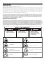 3
3
-
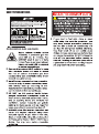 4
4
-
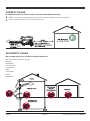 5
5
-
 6
6
-
 7
7
-
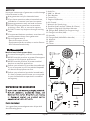 8
8
-
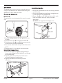 9
9
-
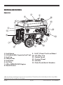 10
10
-
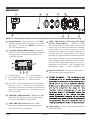 11
11
-
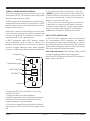 12
12
-
 13
13
-
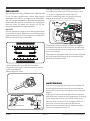 14
14
-
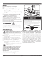 15
15
-
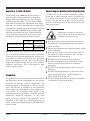 16
16
-
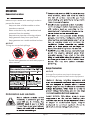 17
17
-
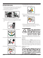 18
18
-
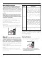 19
19
-
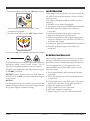 20
20
-
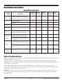 21
21
-
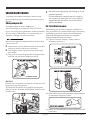 22
22
-
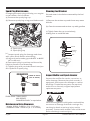 23
23
-
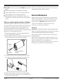 24
24
-
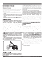 25
25
-
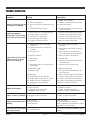 26
26
-
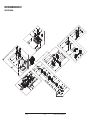 27
27
-
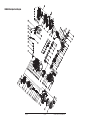 28
28
-
 29
29
-
 30
30
-
 31
31
-
 32
32
-
 33
33
-
 34
34
-
 35
35
-
 36
36
-
 37
37
-
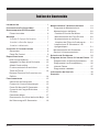 38
38
-
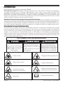 39
39
-
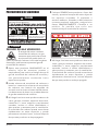 40
40
-
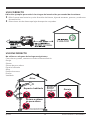 41
41
-
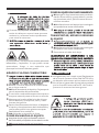 42
42
-
 43
43
-
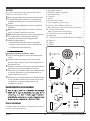 44
44
-
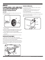 45
45
-
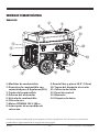 46
46
-
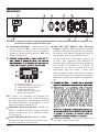 47
47
-
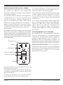 48
48
-
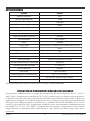 49
49
-
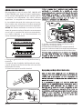 50
50
-
 51
51
-
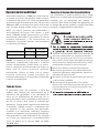 52
52
-
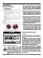 53
53
-
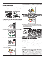 54
54
-
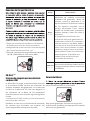 55
55
-
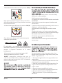 56
56
-
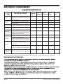 57
57
-
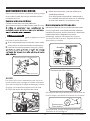 58
58
-
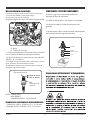 59
59
-
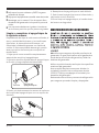 60
60
-
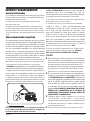 61
61
-
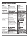 62
62
-
 63
63
-
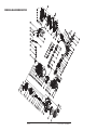 64
64
-
 65
65
-
 66
66
-
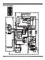 67
67
-
 68
68
-
 69
69
-
 70
70
-
 71
71
-
 72
72


Firman P06702 Manual de usuario
- Categoría
- Generadores de poder
- Tipo
- Manual de usuario
en otros idiomas
- English: Firman P06702 User manual
Artículos relacionados
-
Firman P06701 Manual de usuario
-
-
-
-
-
-
Firman P05703 Guía del usuario
-
-
-