Crosley AEQ6400HE0 Guía de instalación
- Categoría
- Secadoras
- Tipo
- Guía de instalación
Este manual también es adecuado para

I stallati
I structi
Instrucci
instal
I
www.frigidaire.com P/N 134759900A (0709)

CONTENTS
Pre-lnstallation Requirements ...........................................................................................................................................
Electrical Requirements .................................................................................................................................................. 3
Exhaust System Requirements ...................................................................................................................................... 3-4
Gas Supply Requirements ............................................................................................................................................ 4-5
Location of Your Dryer.................................................................................................................................................... 5
Rough-In Dimensions ..................................................................................................................................................... 6
Mobile Home Installation ............................................................................................................................................... 7
Unpacking ................................................................................................................................................................... 7
Reversing Door Swing................................................................................................................................................. 8
Electrical Installation .................................................................................................................................................... 9
Grounding Requirements .............................................................................................................................................. 9
Electrical Con nections--3-wire ....................................................................................................................................... 9
Electrical Connections--4-wire ........................................................................................................................................ 10
Gas Connection ............................................................................................................................................................ 10
General Installation ....................................................................................................................................................... 10
Replacement Parts........................................................................................................................................................ 10
Espahol .................................................................................................................................. 11-20
SAFETY INSTRUCTIONS
Clothes dryer installation and service must be performed by a qualified installer, service agency or the gas supplier.
install the clothes dryer according to the manufacturer's instructions and local codes.
Before beginning installation, carefully read these instructions. This will simplify the installation and ensure the dryer is
installed correctly and safely, Leave these instructions near the Dryer after installation for future reference.
NOTE: The electrical serviceto the Dryer must conform with local codes and ordinances and the latest edition of the National Electrical
Code, ANSI/NFPA70, or in Canada, the Canadian electrical code C22.1 part I.
NOTE: The gasserviceto the Dryer must conform with local codes and ordinances and the latest edition of the National FuelGasCode
ANSI Z223.1, or in Canada, CAN/ACG B149.1-2000
NOTE: The Dryer isdesigned under ANSIZ 21.5.1 or ANSI/UL 2158 - CAN/CSA C22.2 No. 112 (latest editions) for HOME USE only.
This Dryer isnot recommended for commercial applications such asrestaurants or beauty salons, etc.
Your safety and the safety of others is very important.
We have provided many important safety messages in the Use & Care Guide, Operating Instructions, Installation Instructions and on
your appliance. Always read and obey all safety messages.
This isthe safety alert symbol. This symbol alerts you to hazards that can kill or hurt you or others. All safety messages
will be preceded by the safety alert symbol and the word "DANGER" or "WARNING". These words mean:
_ You will be killed or seriously injured if you don't follow instructions.
You can be killed or seriously injured if you don't follow instructions.
All safety messages will identify the hazard, tell you how to reduce the chance of injury, and tell you what can happen if the
instructions are not followed.
RISK OF FIRE For your safety the information in this manual must be followed to minimize the risk of fire or
explosion or to prevent property'damage, personal injury or lossof life. SAVE THESEINSTRUCTIONS,
- Do not store or use gasoline or other flammable vapors and liquid in the vicinity of this or any other appliance.
- WHAT TO DO IF YOU SMELL GAS
. Do not try to light any appliance.
, Do not touch any electrical switch; do not use any phone in your building.
, Clear the room, building or area of all occupants.
Immediately call your gas supplier from a neighbor's phone. Follow the gas supplier's instructions.
If you cannot reach your gas supplier, call the fire department.
Installation and service must be performed by a qualified installer, serviceagency or the gas supplier.
PRE-INSTALLATION REQUIREMENTS
Tools and Materials Required for installation:
1. Phillips head screwdriver.
2. Channel-lock adjustable pliers.
3. Carpenter's level.
4. Flat or straight blade screwdriver.
5. Duct tape.
6. Rigid or flexible metal 4 inch (10.2 cm) duct.
7. Vent hood.
8. Pipe thread sealer (Gas).
9. Plastic knife. 2

ELECTRICAL REQUIREMENTS
i ELECTRICDryer
CIRCUIT- Individual 30 amp. branch circuit fused with 30
amp. time delay fuses or circuit breakers.
Use separately fused circuits for washers and dryers, and DO
NOT operate a washer and a dryer on the same circuit.
POWER SUPPLY- 3 wire or 4-wire, 240 volt, single phase, 60
Hz, Alternating Current.
POWER SUPPLY CORD KIT - The dryer MUST employ a 3-
conductor power supply cord NEMA 10-30 type SRDTrated at
240 volt AC minimum, 30 amp., with 3 open end spade lug
connectors with upturned ends or closed loop connectors and
marked for usewith clothes dryers.
WARNING - Risk of Shock. Appliance grounded to neutral
conductor through a link. Grounding through the neutral link is
prohibited for (1) New branch circuit installations (2) mobile
homes; (3) recreational vehicles; and (4) areaswhere local codes
do not permit grounding through the neutral, (1) disconnect the
link from the neutral, (2) use grounding terminal or lead to
ground appliance in accordance with local codes and (3) connect
neutral terminal or lead to branch circuit neutral in usualmanner
(if the appliance isto be connected by means of a cord kit, use
4-conductor cord for this purpose). USECOPPERCONDUCTOR
ONLY. The dryer MUST employ a 4-conductor power supply
cord NEMA 14-30 type SRDTor ST(as required) rated at 240
volt AC minimum, 30 amp., with 4 open end spade lug
connectors with upturned ends or closed loop connectors and
marked for use with clothes dryers. See ELECTRICAL
CONNECTIONSFORA 4-WIRE SYSTEM.
(Canada - 4-wire power supply cord is installed on dryer.)
OUTLET RECEPTACLE- NEMA 10-30R receptacle to be located
so the power supply cord isaccessible when the dryer is in the
installed position. (Canada - NEMA 14-30R receptacle.)
NEMA 10-30R NEMA 14-30R
i GASDryer i
CIRCUIT- Individual 15 amp. branch circuit fused with a 15
amp. maximum time delay fuse or circuit breaker.
POWER SUPPLY - 3 wire, 120 volt single phase, 60 Hz,
Alternating Current.
POWER SUPPLY CORD - The dryer is equipped with a 120
volt 3-wire power cord.
NOTE: Do not under any _ { _l _ _
circumstances remove
grounding prong from
plug.
G PRONG
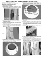
EXHA LIST SYSTEM REQUIREMENTS
Use only 4 inch (10.2 cm) diameter (minimum) rigid or flexible
metal duct and approved vent hood which has a swing-out
damper(s) that open when the dryer is in operation. When the
dryer stops, the dampers automatically close to prevent drafts
and the entrance of insects and rodents. To avoid restricting
the outlet, maintain a minimum of 12 inches (30.5 cm) clearance
between the vent hood and the ground or any other obstruction.
The following are specific requirements for
proper and safe operation of your dryer, Failure to follow
these instructions can create excessive drying times and
fire hazards.
Do not install a clothes dryer with flexible
plastic venting materials. If your present system is made up
of plastic duct or metal foil duct, replace it with a rigid or flexible
metal duct. In Canada and the United States if metal (foil type)
duct is installed, it must be of a specific type identified by the
appliance manufacturer as suitable for use with clothes dryers
and in the United States must also comply with the Outline for
Clothes Dryer Transition Duct, UL standard 2158A. Flexible
venting materials are known to collapse, be easily crushed and
trap lint. Theseconditions will obstruct clothes dryer airflow and
increase the risk of fire. Ensure the present duct is free of
any lint prior to installing dryer duct.
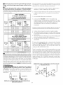
I
Correct Incorrect
l
DO DON'T
© .... C
_ Incorrect
_- Risk of Fire - A clothes dryer must be
exhausted outdoors. Do not exhaust dryer into a chimney, a
wall, a ceilinq, an attic, a crawl space or any concealed space
of a building A clothes dryer produces combustible lint. If the
dryer is not exhausted outdoors some fine lint will be expelled
into the laundry area. An accumulation of lint in any area of the
home can create a health and fire hazard. The dryer must be
connected to an exhaust outdoors. Regularly inspect the
outdoor exhaust opening and remove any accumulation of lint
around the outdoor exhaust opening and in the surrounding
area.

Do not allow combustible materials (for
example: clothing, draperies/curtains, paper) to come in
contact with exhaust system. The dryer MUST NOT be
exhausted into a chimney, a wall, a ceiling, or any concealed
space of a building which can accumulate lint, resulting in a fire
hazard.
Exceeding the length of duct pipe or number
of elbows allowed in the "MAXIMUM LENGTH" charts can
cause an accumulation of lint in the exhaust system. Plugging
the system could create a fire hazard, aswell as increase drying
times.
Do not screen the exhaust ends of the vent
system, nor use any screws, rivets or other fastening means
that extend into the duct and catch lint to assemble the
exhaust system. Lint can become caught in the screen, on the
screwsor rivets, clogging the duct work and creating afire hazard
aswell as increasing drying times. Use an approved vent hood
to terminate the duct outdoors, and sealalljoints with duct tape.
All male duct pipe fittings MUSTbe installed downstream with
the flow of air.
Explosion hazard. Do not install the dryer
where gasoline or other flammables are kept or stored. If
the dryer is installed in a garage, it must be a minimum of 18
inches (45.7 cm) above the floor. Failure to do so can result in
death, explosion, fire or burns.
I. Connect an inclined or digital manometer between the
dryer and the point the exhaust connects to the dryer.
2. Set the dryer timer and temperature to air fluff (cool down)
and start the dryer.
3. Read the measurement on the manometer.
4. The system back pressure MUSTNOTbe higher than 0.75
inches of water column. If the system back pressure is
less than 0.75 inches of water column, the system is
acceptable. If the manometer reading is higher than 0.75
inches of water column, the system is too restrictive and
the installation is unacceptable.
Although vertical orientation of the exhaust system isacceptable,
certain extenuating circumstances could affect the performance
of the dryer:
• Only the rigid metal duct work should be used.
• Venting vertical through a roof may expose the exhaust
systemto down drafts causing an increase in vent restriction.
• Running the exhaust system through an uninsulated area
may cause condensation and faster accumulation of lint.
• Compression or crimping of the exhaust system will cause
an increase in vent restriction.
The exhaust system should be inspected and cleaned a minimum
of every 18 months with normal usage. The more the dryer is
used, the more often you should check the exhaust system and
vent hood for proper operation.
MAXIMUM LENGTH
of 4" 110.2 cm) Dia. Rigid Metal Duct
VENT HOOD TYPE
Number (Preferred)
110.2 cm) (6.35 cm)
0 60 ft.(l&28 m) 48 ft.114.63 m)
1 52 ft.(15.84 m_ 40 ft.(12.19 m)
2 44 ft.113.41 m) 32 ft. 19.75m)
3 32 ft.(9.75 m) 24 ft. (7.31 m)
4 28 ft.(8.53 m) 16ft. (4.87m)
MAXIMUM LENGTH
Number of 4" (10.2 cm) Dia. Flexible Metal Duct
VENT HOOD TYPE
of (Preferred)
4,,F
(10.2 cm) (6.35 cm)
0 30ft. 19.14m) 18ft. IS.49m)
1 22 ft. (6.71 m) 14 ft. (4.27 m)
2 14 ft. (4.27 m) 10 ft. (3.05 m)
3 NOT RECOMMENDED
INSTALL MALE FITTINGSIN CORRECT DIRECTION
In installations where the exhaust system isnot described in the
charts, the following method must be used to determine if the
exhaust system isacceptable:
EXHAUST DIRECTION
All dryers shipped from the factory are set up for rear exhausting.
However, on electric dryers, exhausting can be to the right or left
side of the cabinet or the bottom of the dryer. On gas dryers,
exhausting can be to the right side of the cabinet orthe bottom of
the dryer. Directional exhausting can be accomplished by installing
Exhaust Kit, P/N 131456800, available through your parts
distributor. Follow the instructions supplied with the kit.
EXHAUST DUCT LOCATING DIMENSIONS
k _2//- SAMEASOTHERSIDE
_'J_" -/" 57/8"
GAS SUPPLY REQUIREMENTS
Replace copper connecting pipe that is not
plastic-coated. Stainless steel or plastic-coated brass MUST
be used.
I. Installation MUST conform with local codes, or in the absence
of local codes, with the National Fuel GasCode, ANSI Z223.1
(latest edition).
2. The gas supply line should be of 1/2 inch (1.27 cm) pipe.
3. If codes allow, flexible metal tubing may be used to connect
your dryer to the gas supply line. The tubing MUST be
constructed of stainless steel or plastic-coated brass.
4. The gas supply line MUSThave an individual shutoff valve.
4

5. A 1/8 inch (0.32 cm) N.P.T.plugged tapping, accessible for test gauge connection, MUST be installed immediately upstream
of the gas supply connection to the dryer.
6. The dryer MUST be disconnected from the gas supply piping system during any pressuretesting of the gassupply piping system
at test pressures in excess of I/2 psig (3.45 kPa).
7. The dryer MUSTbe isolated from the gas supply piping system during any pressure testing of the gas supply piping system
at test pressures equal to or lessthan
I/2 psig (3.45 kPa).
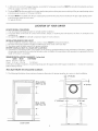
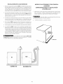
LOCATION OF YOUR DRYER
DO NOT INSTALL YOUR DRYER:
1. In an area exposed to dripping water or outside weather conditions.
2. In an area where it will come in contact with curtains, drapes, or anything that will obstruct the flow of combustion and
ventilation air.
3. On carpet. Floor MUSTbe solid with a maximum slope of 1 inch (2.54 cm).
INSTALLATION IN RECESSOR CLOSET
I. A dryer installed in a bedroom, bathroom, recessor closet, MUST be exhausted outdoors.
2. No other fuel burning appliance shall be installed in the same closet asthe Gasdryer.
3. Your dryer needs the space around it for proper ventilation.
DO NOT install your dryer in a closet with a sofid door
4. A minimum of 120 square inches (774.2 square cm) of opening, equally divided at the top and bottom of the door, is required.
Air openings are required to be unobstructed when a door isinstalled. A Iouvered door with equivalent air openings for the full
length of the door isacceptable.
MINIMUM INSTALLATION CLEARANCES - Inches (cm)
SIDES REAR TOP FRONT
Alcove 0(0cm) 0(0cm)
Closet 0 (0 cm) 0 (0 cm) 1 (2.54 cm)
Closet door ventilation required: 2 Iouvered openings each 60 square inches (387 square centimeters) -- 3 inches (7.6 cm) from
bottom and top of door.
This dryer MUST be exhausted outdoors.
5. The following illustrations show minimum clearance dimensions for proper operation in a recessor closet installation.
II
--_ii*--o" (o cm)
H
ii
II
1" (2.54 cm) _i_ 0" (0 cm)
II ii
II _11 _
0" (0 cm)
CLOSET DOOR

inches (cm)
To front of cabinet
28.25"(71.76)
To clear kobs
28.75"(73.03)
To clear door
29.5"(74.93)
To clear open door
53"(134.62)
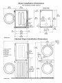
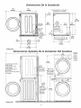
Dryer Installation Dimensions
Free-Standing & Under Counter
24"
(60.96) Electrical supply
22%"
(57.79)
24318"
(61,91)
27"
(68.58)
5.875"(14.93)
Tobase
_exhaust
29%"
175.57)
: 5.0"(12,7) 5"
Center line (12.70)
, height for rear, __
right, left vent
/
4.375"(11.12)
To side
exhausts
15/8"
(4.13)
25/8"
(6.67)
13½"
(34.29)
To rear
and base
exhausts
/
(
\
34'
(86.:i6)
J
Gass ,y t2.25,,
(5.72)
pipe on rear
of unit
27"
(68.56)
Stacked Dryer installation Dimensions
I
Gas
supply
pipe on
rear of
unit \
2.375"1
(6.03)
38.25"
(97.16)
T
72,00"
(172.88)
41.00"
(97.16)
Center line
height for
rear, right,
left vents
inches (cm)
t 27"
(68.58)
(34.29) _ \
_ X
= : : ? _
] , , .... ' ,i
%
35"
(68.90)
Electrical
supply on
rear of
_ unit

MOBILE HOME iNSTALLATiON
1. Dryer MUST be exhausted outside (outdoors, not beneath the
mobile home) using metal ducting that will not support
combustion. Metal ducting must be 4 inches (10.16 cm) in
diameter with no obstructions. Rigid metal duct is preferred.
2. If dryer is exhausted through the floor and area beneath the
mobile home is enclosed, the exhaust system MUST terminate
outside the enclosure with the termination securely fastened
to the mobile home structure.
3. When installing a gas dryer into a mobile home, a provision
must be made for outside make up air. This provision is to be
not less than twice the area of the dryer exhaust outlet.
4. This dryer MUST be fastened to the floor. Mobile Home
Installation Kit No. 346764 is available from your dealer.
5. Refer to pages 2 and 3 for other important venting
requirements.
6. Installation MUST conform to current Manufactured Home
Construction & Safety Standard (which is a Federal Regulation
Title 24 CFR-Part 32-80) or when such standard is not applicable,
with American National Standard for Mobile Homes.
The dryer is designed under ANSI Z 21.5.1 or
ANSI/UL2158 - CAN/CSA C22.2 (latest editions) for HOME USE
only.
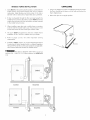
UNPACKING
1. Using a rug, blanket or a piece of cardboard packing to protect
the floor, carefully lay the dryer on its left side and remove the
foam shipping base.
2. Return the dryer to an upright position.
FOAM
SHIPPING
_P_C KING
Q
Correct incorrect
DO
C
incorrect

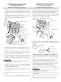
DRYER DOOR REVERSAL INSTRUCTIONS
Be sure to wear gloves while reversing the door assembly.
You will need a #2 square head drive screwdriver, a Phillips head
screwdriver and pliers.
1. Open the dryer door.
2. Remove the two screws that secure the door hinge to the front panel.
Remove the bottom screw first. Support the door assembly
firmly before removing the top screw.
7. Remove the two hinge attachment screws, one square plug, two
round plugs and one metal strike from the inner door.
attachmeJ
screw
plug
3. Hold the door near the top and bottom and lift to remove the door.
4. Place door assembly face down on a padded, flat surface.
5. Pull out the two round plugs and slide the rectangular plug up and out
of the front panel. Use care to avoid scratching the surface or damaging
the plugs. Reinstall the plugs in Step 9.
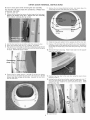
8,
9.
Rotate the hinge and reattach it to the opposite side of the inner door.
Dispose of the old metal strike and install the new strike (included in
the literature pack) in the opposite side of the inner door. Reinstall the
round plugs and square plug in the holes left by the hinge and hinge
screws.
10. Remove the hinge cutout plug. Rotate it and install it on the opposite
side of the outer door.
6. Remove the five longer screws (1 through 5) and the two shorter
screws (6 and 7) that attach the inner door to the outer door. Do not
remove any other screws at this time. Separate the inner door
from the outer door.
11. Reattach the inner door to the outer door using the seven screws
removed in Step 6.
12. Holding the door at the top and bottom, insert the hinge post in the "T_'
slot in the front panel and lower to align the screw holes. While
supporting the door, install the two screws removed in Step 2. Install
the top screw first.
13. Close the door.
8

ELECTRICAL INSTALLATION
i ELECTRICDryer
The following are specific requirements for
proper and safe electrical installation of your dryer. Failure
to follow these instructions can create electrical shock and/
or a fire hazard.
This appliance MUST be properly grounded.
Electrical shock can result if tile dryer is not properly grounded.
Follow the instructions in this manual for proper grounding.
Do not use an extension cord with this dryer.
Someextension cords are not designed to withstand tile amounts
of electrical current this dryer utilizes and can melt, creating
electrical shock and/or fire hazard. Locate the dryer within reach
of the receptacle for the length power cord to be purchased,
allowing some slack in the cord. Refer to the pre-installation
requirements in this manual for the proper power cord to be
purchased.
A U.L. approved strain relief must be installed
onto power cord. If tile strain relief is not attached, tile cord
can be pulled out of the dryer and can be cut by any movement
of the cord, resulting in electrical shock.
Do not use an aluminum wired receptacle
with a copper wired power cord and plug {or vice versa).
A chemical reaction occurs between copper and aluminum and
can cause electrical shorts. The proper wiring and receptacle
is a copper wired power cord with a copper wired
receptacle.
NOTE: Dryersoperating on 208 volt power supplywill have longer
drying times than operating on 240 volt power supply.
GROUNDING REQUIREMENTS
USA ELECTR/CDryer j
Improper connection of the equipment grounding
conductor can result in a risk of electrical shock. Check with a
licensedelectrician ifyou are in doubt asto whether the appliance
isproperly grounded.
For a grounded, cord-connected dryer:
I. Tile dryerMUSTbe grounded. Intile event of a malfunction
or breakdown, grounding will reducethe riskof electricalshock
by a path of least resistance for electrical current.
2. If your dryer isequipped with a power supply cord having an
equipment-grounding conductor and a grounding plug, the
plug MUST be plugged into an appropriate, copper wired
receptacle that is properly installed and grounded in
accordance with all local codes and ordinances. If in doubt,
call a licensed electrician. Do not modify plug provided
with the appliance.
For a permanently connected dryer:
1. Tile dryerMUSTbe connected to a grounded metal, permanent
wiring system; or an equipment grounding conductor must be
run with the circuit conductors and connected to the
equipment-grounding terminal or lead on the appliance.
[ Canadian ELECTR/CDryer i
Improper connection of the equipment grounding
conductor can result in a risk of electrical shock. Check with a
licensed electrician ifyou are in doubt asto whether the appliance
isproperly grounded.
9
Fora qrounded, cord-connected dryer:
I. The dryer must be grounded. In the event of a malfunction
j or breakdown, grounding will reduce the risk of electrical
shock by a path of least resistance for electrical current.
2. Sinceyour dryer isequipped with a power supply cord having
an equipment-grounding conductor and a grounding plug,
the plug must be plugged into an appropriate outlet that is
properly installed and grounded in accordance with all local
codes and ordinances. If in doubt, call a licensed electrician.
Do not modify plug provided with the appliance.
i ,4LLG,4SDryers i
1.The dryer isequipped with a three-prong (grounding) plug
for your protection against shock hazard and should be
plugged directly into a properly grounded three-prong
receptacle. Do not cut or remove the grounding prong
from the plug.
ELECTRICALCONNECTIONS
FOR 3- WIRE SYSTEM
i
I.
1
USA ELECTRICDryer
Removethe screws securing the terminal block accesscover
and the strain relief mounting bracket located on the back of
the dryer upper corner.
Install a U.L approved strain relief into the power cord entry
hole of the mounting bracket. Finger tighten the nut only at
this time.
GREEN
SILVER
SCREW TERMINAL
NEUTRAL
GROUND
WIRE
tUT
TIGHTEN NUT
TO THESE
tREADS
BRACKET POWER CORD
3. Thread a U.L approved 30 amp. power cord, NEMA 10-30
type SRDT,through the strain relief.
4. Attach the power cord neutral (center wire) conductor to the
silver colored center terminal on the terminal block. Tighten
the screw securely.
5. Attach the remaining two power cord outer conductors to
the outer brass colored terminals on the terminal block.
Tighten both screws securely.
Do not make a sharp bend or crimp wiring/
conductor at connections.
6. Reattach the strain relief mounting bracket to the back of
the dryer with two screws. Tighten screws securely.
7. Tighten the screws securing the cord restraint firmly against
the power cord.
8. Tighten the strain relief nut securely so that the strain relief
does not turn.
9. Reinstall the terminal block cover.

ELECTRICALCONNECTIONS FOR 4-WIRE SYSTEM
1 USAELECTRICDryer ]
1. Removethe screws securing the terminal block access cover
and the strain relief mounting bracket located on the back of
the dryer upper corner.
2. Install a U.L approved strain relief in the entry hole of the
mounting bracket. Fingertighten the nut only at this time.
3. Remove the ground wire from the green ground screw
located above the terminal block.
GREEN POWER CORD
GREEN
SILVERTERMINAL
SCREW f TERMINAL
BLOCK
TIGHTEN
NUT
GROUND WHITE TO THESE
WIRE NUT FHREADS
STRAIN
RELIEF
BRACKET_
POWER
CORD
4. Thread a U.L approved 30 amp power cord, NEMA 14-30
type STor SRDTthrough the strain relief.
TYPICAL 4 _ g |_ T'rPICAL 4 BLACK
COND UCTO_J COND UCTOR _ WHITE
30 AMP NEMA 14-30 TYPE 5RDT OR ST _GREEN
5. Attach the green power cord ground wire to the cabinet with
the green ground screw.
6. Attach the white (neutral) power cord conductor from the
power cord and the neutral ground wire from the dryer harness
to the silver-colored center terminal on the terminal block,
Tighten the screw securely.
7. Attach the red and black power cord conductors to the outer
brass-colored terminals on the terminal block,
Do not make a sharp bend or crimp wiring/
conductor at the connections.
8. Tighten the screws securing the cord restraint firmly against
the power cord.
9. Tighten the strain relief nut securely so the strain relief does
not turn.
l O.Reinstallthe terminal block accesscover.
GAS CONNECTION
1. Remove the shipping cap from gas pipe at the rear of the
dryer.
NOTE: DO NOT connect the dryer to LR gas servicewithout
converting the gasvalve. An LR conversion kit must be installed
by a qualified gas technician.
2. Connect a 1/2 inch (1.27 cm) I.D. semi-rigid or approved pipe
from gassupply line to the 3/8 inch (0.96 cm) pipe located on
the back of the dryer (see pages 6 and 7), Use a 1/2 inch to
3/8 inch (1.27 cm to 0.96 cm) reducer for a connection. Apply
an approved thread sealer that is resistant to the corrosive
action of liquefied gases on all pipe connections.
3. Open the shutoff valve in the
gas supply line to allow gas VALVEOPEN/
to flow through pipe. _AS FLOW
4. Test all connections by brushing POSITION
on a soapy water solution.
NEVER test for gas leaks with an open flame.
10
GENERAL INSTALLATION
1. Connect the exhaust duct to outside exhaust system (see
pages 3 and 4). Use duct tape to seal all joints.
2. With the dryer in its final position, adjust one or more of the
legs until the dryer is resting solid on all four legs. Place a
level on top of the dryer. The dryer MUST be level and
resting solid on all four legs.
3. Plug the power cord into a grounded outlet. NOTE:Check to
ensure the power is off at circuit breaker/fuse box before
plugging the power cord into the outlet.
4. Turn on the power at the circuit breaker/fuse box.
Before operating the dryer, make sure the
dryer area is clear and free from combustible materials,
gasoline, and other flammable vapors. Also see that
nothing (such as boxes, clothing, etc.) obstructs the flow
of combustion and ventilation air.
5. Run the dryer through a cycle check for proper operation.
NOTE: On gas dryers, before the burner will light, it is
necessaryfor the gas line to be bled of air. If the burner does
not light within 45 seconds the first time the dryer isturned
on, the safety switch will shut the burner off. If this happens,
turn the timer to "OFF" and wait 5 minutes before making
another attempt to light.
6. If your dryer does not operate, please review the "Avoid Ser-
vice Checklist" located in your Use and Care Guide before
calling for service.
7. Placethese instructions in a location near the dryer for future
reference.
NOTE: A wiring diagram is located inside the dryer console
or under the top panel.
8. To stack your dryer on a compatible washer, visit web site
www.frigidaire.com, call your local dealer or call the Toll
Freenumber (1- 800- 444- 4944) to find your localdistributor
to purchase stacking kit accessory part number STACKIT3.
REPLA CEMEN T PA RTS
Pedestal
A pedestal accessory, Model No. APWD15W (White),
APWD 15GB (Glader Blue), APWD 15P(Platinum) and
APWD15E(Black), specifically designed for this dryer may
be used when elevating the dryer for easeof use. Failure
to use accessories certified by the manufacturer could
result in personal injury, propertydamageor damagetothe
dryer.
If replacements parts are needed for your dryer, contact the source
where you purchased your dryer, call 1-800-944-9044, or visit
our website, www.frigidaire.com, for the Frigidaire Company
Authorized Parts Distributor nearest you.
Label all wires prior to disconnection when servicing
controls. Wiring errors can cause improper and dangerous
operation. Verify proper operation after servicing.
Destroy the carton and plastic bags after the dryer
is unpacked. Children might usethem for play. Cartons covered
with rugs, bedspreads, or plastic sheets can become airtight
chambers causing suffocation. Placeall materials in a garbage
container or make materials inaccessible to children.
The instructions in this manual and all other
literature included with this dryer are not meant to cover every
possiblecondition and situation that mayoccur.Good safe practice
and caution MUST be applied when installing, operating and
maintaining any appliance.
Printed in U.S.A.

Tabla de Materias
Requerimientos de instalaciOn preliminares .......................................................................................................................... 12
Requerimientos elOctricos................................................................................................................................................... 12
Requerimientos del sistema de escape............................................................................................................................. 12-13
Requerimientos del suministro de gas................................................................................................................................... 14
UbicaciOn de su secadora ................................................................................................................................................... 14
Dimensiones para la instalaciOn........................................................................................................................................... 15
InstalaciOn en casas mOviles............................................................................................................................................... 16
Desembalaje ................................................................................................................................................................... 16
Puerta reversible ............................................................................................................................................................... 17
InstalaciOn electrica .......................................................................................................................................................... 18
Requerimientos para la puesta a tierra ................................................................................................................................. 18
Conexi0nes elOctricas - trifilares .......................................................................................................................................... 19
ConexiOnes elOctricas - tetrafilares ....................................................................................................................................... 19
InstalaciOn ....................................................................................................................................................................... 20
Piezas de recambio ........................................................................................................................................................... 20
1
SEGURIDAD de SECADORA
La instalacion y el servicio de la Secadora de ropa se deben realizar pot un instalador calificado, la agencia de servicio o
el surtidor de gas.
Instale la Secadora de ropa segun las instrucciones del fabricante y los cOdigos locales.
Antes de cornenzar la instalaciOn, lea cuidadosamente estasinstrucciones. Esto simplificara la instalaciOny asegurara que la secadora
se instale correctamente y de manera segura. Despues de completar la instalaciOn, coloque estas instrucciones cerca de la secadora
para referencia futura.
NOTA: Laalimentaci0n elOctricapara lasecadora debera cumplir con loscOdigosyreglamentos localesycon laOltima ediciOndel COdigo
Electrico Nacional, ANSI/NFPA70 o en Canada CSA C22.1 COdigo ElOctricoCanadiense, Parte I.
NOTA: Laalimentaci0n de gaspara la secadora debera cumplir con loscOdigosy reglamentos localesy con la Oltima ediciOndel COdigo
Nacional para GasesCombustibles, ANSIZ223.1 o en Canada CAN/CGA B149.12.
NOTA: Lasecadora esta clasificada para USODOMESTICOsolamente, de acuerdo con la norma ANSI Z21.5.1 o ANSI/UL2158 - CAN/
CSA C22.2 No. 112 (las Oltimasedici0nes). Estasecadora no se recomienda para uso commercial tal como en restaurantes, salones de
belleza, etc.
Su seguridad y la seguridad de terceros son muy importantes.
Hemos proporcionado muchos mensajes irnportantes para la seguridad en las Instrucciones de Operaci0n del Manual de Uso y
Mantenimiento, lasInstrucciones de Instalaci0n yen el mismo aparato. Siempre lea y obedezca todos los mensajes para seguridad.
_Este simbolo significa alerta. Estesimbolo Io alerta acerca de peligros que pueden matar o lesionar, tanto a usted como a otras
personas. Todos los mensajes de seguridad seran precedidos por el simbolo de alerta para su seguridad y la palabra "PELIGRO o
ADVERTENCIA " (DANGER" o WARNING). Estaspalabras significan:
_ PELIGRO(DANGER) Usted morira o resultara seriamente lesionado si no sigue las instrucciones siguientes.
ADVERTENCIA (WARNING) Usted puede modr o resultar seriamente lesionado si no sigue las
instrucciones siguientes.
Todos los mensajes de seguridad identificaran el peligro, le diran a usted cOmo reducir la posibilidad de lesion y tambien
qu_ puede suceder si no se siguen las instrucciones.
RIESGODEINCENDIO. Para suseguridad, siga lasinstrucciones contenidas en este manual a fin de reducir a
un minimo los riesgos de incendio o explosion o para evitar da_os materiales, lesiones personales o la muerte. GUARDEESTAS
INSTRUCCIONES.
Noalmacene niutilice gasolina uotrosvapores yliquidos inflamables en laproximidad de _ste o de cualqu ierotro artefacto electrico.
QUE DEBEHA CERSIPERCIBEOLORA GAS
. Notrate de encender ning0n artefacto el_ctrico.
. Notoque ning0n interruptor el_ctrico; no usening0n telefono en suedificio.
. Haga salir atodos los ocupantes de la habitaciOn, del edificio y del lugar.
. Llamea suproveedor de gasdesde el tel_fono de un vecino. Siga lasinstrucciones del proveedor de gas.
. Si no Iogra comunicarse con su proveedor de gas, Ilame al departamento de bomberos.
Lainstalaci0n y el servicio de mantenimiento debe de realizarlos un instalador calificado, la agencia de servicios o el proveedor de gas.
REQ UERIMIENTOS DE INS TALA CION PRELIMINA RES
Herramientas y materiales necesados para la instalaciOn:
I. Destornillador Phillips
2. Alicates universales
3. Nivel de carpintero
4. Destornillador para tornillo de cabeza plana o recta
5. Cinta para ductos
6. Ducto metalico rigido o flexible de 4" (10,2 cm)
7. Caperuza de salida
8. Sellador de tuberias (gas)
9. Un cuchillo de plastico
11

REQUERIMIENTOS ELECTRICOS
l SecadorasELECTRICAS 1
CIRCUlTO- (ircuito derivado individual de30 amperios, confusibles
de 30 amp. del tipo de retardo o disyuntores.
Use circuitos separados con un interrupter o fusible para las
lavadoras y las secadoras y no haga funcionar la lavadora y
secadora en el mismo circuito.
ALIMENTACIONELECTRICA- Corriente alterna, monofasica, 60
Hz, 240 voltios; trifilar o tetrafilar.
KITDE CABLE TOMACORRIENTE- Lasecadora seDEBE usarun
cable tomacorriente trifilar NEMA 10-30 tipo SRDTpara un voltaje
nominal minimo de 240 voltios CA, 30 amp, con 3 conectores de
horquillas con terminales abiertos y extremes dirigidos hacia arriba
o conectores de anillo cerrado y marcados para use en secadoras
de ropa.
AVERTISSEMENT-Risquedechoc#lectrique. Unappareil misa
la terre a I'aide d'un lien ou cable conducteur neutre. Laraise a la
terre aI'aide d'un conducteu rou cable neutre est interdite darts los
cas suivants : (1) los installations de nouveau circuit d_vir_ (2) los
maisons mobiles (3) lesv_hicules r_cr6atifs ou caravanes et (4) los
r6gions oQloscodes Iocauxinterdisent laraisea laterre a I'aide d'un
cableou conducteur neutre. (1)D_branchez leconducteur ou cable
du neutre, (2) utilisez la borne de raiseala terre ou le cablede raise
a la terre de I'appareil conform_ment aux codes Iocaux et (3)
connectez ou branchez la borne neutre ou le cable au neutre du
circuit d_vir_de lamani_re habituelle(si I'appareil doit _tre connect_
a I'aide d'un cordon, utilisez un cordon a4 cables ou fils pour ce
faire). N'UTILISEZQUEDESCABLESOUFILSENCUIVRE. SeDEBE
utilizar un cord6n electrico tetrafilar NEMA 14-30 tipo SRDTo ST
(come seanecesario)para un voltaje nominal minimo de240 voltios
CA, 30 amp con 4 conectores de horquillas con terminales abiertos
y extremes dirigidos hacia arriba o conectores de anillo cerrado y
marcados para use en secadoras de ropa. Ver CONEXIONES
ELECTRICASPARASISTEMASTETRAEILARES.
(Canada- un cord6n de suministro de energia de 4 alambres es
instalado en la secadora.)
TOMACORRIENTE - Eltomacorriente NEMA I 0-30R debe estar
ubicadode maneraqueelcabletomacorrientelleguehasta61
cuando la secadora este instalada. (Canada - receptaculo NEMA
14-30R.)
i
NEMA 10-30R NEMA 14-30R
Secadoras a GAS ]
CIRCUITO - Circuito individual derivado de 15 amp, con fusibles
de 15 amp. de retardo maximo o disyuntor.
ALIMENTACION ELECTRICA - Corriente alterna, monofasica,
60 Hz, 120 voltios, trifilar.
CABLE TOMACORRIENTE- Lasecadora esta equipada con un
cabletomacorriente trifilar para 120 voltios.
NOTA: No saque per
ningun motive la
pierna de puesta a
tierra del enchufe.
ESPIGA DE
A
TIERRA
REQUERIMIENTOS DEL SISTEMA DE ESCAPE
Utilice solamente ductos met41icos, rigidos o flexibles de 4"
(10,2 cm) de diametro (minimo) y una tapa de salida de use
aprobado, con bisagras que se abren cuando la secadora se
encuentra en funcionamiento. Cuando la secadora se detiene,
la tapa se cierra automaticamente para evitar las corrientes de
aire y la entrada de insectos y roedores. Para evitar obstruir la
salida, mantenga una altura libre minima de 12" (30,5 cm) entre
la tapa de salida y el piso o entre cualquier otra obstrucciOn.
Los siguientes requerimientos son
espedficos para el fundonamiento correcto y seguro de su
secadora. El incumplimiento de estas instrucdones puede
causar prolongad6n excesiva del tiempo de secado y riesgos
de incendio.
[]No instale la Secadora con materiales de ventilaciOn plasticos
flexibles. EnCanadaylosEstadosUnidos siel conducto esde metal
(tipo hoja de aluminio), _ste debe ser de un tipo especifico
identificado per el fabricante, recomendado para el use con
Secadoras; yen los EstadosUnidos debe ademas cumplir con la
norma UL2158A. Losmateriales de ventilaci6n flexibles sepueden
colapsaro apachurrar facilmente yatrapar pelusa. Estascondiciones
obstruiran lacirculaciOnde airedela Secadorade ropa yaumentaran
el riesgo de incendio.
Sisusistema de escape actual tiene ductos de plastico o de laminas
metalicas delgadas, reemplacelo con un ducto metdico rigido o
flexible. Asegurese de que los ductos existentes no tengan
pelusas antes de instalar el ducto de la secadora.
CORRECTO
_,_!_i!;i!i!ii_!!;__i_l:i_l:i_;!_!!!_l!!_!!!!!!_!!_!!!!!!_!!_!!!!!!_!!_!!!!!!_!!_!!!!!!_!!_!!!!!!_!i_ll_!li_I_ii_iii!_!!!__!!_i!!!!!_!!_!!!!!!_!!_!!!!!!_!!_!!!!!!_!!_!!!!!!_!!_!!!!!!_!!_!!!!!!_!!_!!!i!i_ii!i!_I
INCORRECTO
L
CORRECTO
[] Risque d'incendie- una Secadora de ropa sedebe ventilar
alaire libre. No ventile la Secadoraen una chimenea, una pared,
un techo, un atico, un espacio cerrado o ningOn espacio encubierto
del edificio. Unesecheusea linae produit de lacharpiecombustible.
Siel escape de la secadora no sediriqe al exterior, alqunas pelusas
finas seransopladas hacia el recinto donde seefectL_ael lavado. La
acumulaciOn de pelusas en cualquier lugar de lacasa,puede crear
un peligro para lasalud yun riesgo de incendio. Las_cheuse dolt
@treconnectee _une bouche d"evacuation vers I'ext_rieur du
b&timentou del'immeuble. Vousdevezinspecter r_gu%rement
I'_vent ext_rieur et enlever toute accumulation de charpie autour
de I'_vent et dans la cavit_ du conduit d'_vacuation.
12

No permita que los materiales combustibles (por ejemplo:
la ropa, cortinas/cortinajes, papel) tengan contacto con los
ductos.
Exceder la Iongitud del conducto rigido o los numeros
de codos permitidos en los diagramas "LARGO MAXIMO"
puede disminuir lacapacidad de de desahogo del sistema. Obstruir
el conducto puede provocar peligro deincendio, asicomo aumentar
el tiempo de secado.
LARGO MAXIMO
del Conducto Metafico Rigido
de 4" (10,2 cm) de Diametro
Numero
de Codes
a 90 °
0
I
2
3
4
TIPO DE CAPERUZA DE SALIDA
(Preferido)
.4 4,,F
(1¢2 cm)
60 pies
52 pies
44 pies
32 pies
28 pies
Apersianada
(18,28 m)
(15,84 m)
(13,41 m)
(9,75 m)
(8,53 m)
_r6.3scm_
48 pies(14,63 m)
40 pies(12,19 m)
32 pies (9,75 m)
24 pies (7,31 m)
16 pies (4,87 m)
Numero
de Codos
a 90°
0
1
2
3
LARGO MAXIMO
del Conducto Met4fico Flexible
de 4" (10,2 cm) de Diametro
TIPODE CAPERUZA DESALIDA
(Preferido)
Apersianada
(10,2 cm)
30 pies (9,14m)
22 pies (5,71rn)
14 pies (4,27rn)
(6.35cm)
18 pies (5,49 m)
14 pies (4,27 m)
10 pies (3,05 m)
NO RECOMENDADO
_Noobstruyalosextremosdeltubodeventilacion niutilice
tornillos, remaches u otros medios de fijaciOn que puedan obstruir
el conducto vatrapar pelusa. Laspelusaspodrian quedar atrapadas
en losfiltros, en lostornillos o en losremaches, Iocual obstruiria el
sistema de escapeycreariaun riesgode incendio, asicomotambi_n
prolongaria el tiempo de secado. Use una caperuza de salida
adecuada para el extremo del ducto que salga al exterior de la
vivienda yselletodas lasjuntascon cinta adhesivapara ductos. Todos
losaccesoriosde tuberia machos,DEBENser instaladosaguasabajo
del flujo de aire.
_rv.__ Riesgo de explosion. No instale la
secadora donde se guarda gasolina u otros materiales
inflamables. Silasecadora seinstala en un garage, ella debe estar
porlomenos 8pulgadas(45,7cm) porencimadelsuelo. El
incumplimiento )uede resultar en lamuerte, explosion, incendio, o
quemaduras. !
CORRECTO INCORRECTO
INSTALE EL LADO MACHO DELOS ACCESORIOS EN LA
DIRECCION CORRECTA
13
Paralas instalaciones cuyo sistema de desahogo no seencuentre
en el diagrama, se puede utilizar el mOtodo a continuaciOn para
determinar si el sistema de desahogo es apropiado.
I. Conecte un manOmetro a tubo inclinado o digital entre la
secadora y el union de desahogo de la secadora.
2. Ponga el contador de tiempo de la secadora y la temperatura
a aire frio (enfriamiento), y la secadora en la posiciOn de
marcha.
3. Lea la medida indicada en el manOmetro.
.
Labaja presi6n NO DEBE exceder 0.75 pulgada de la
columna deagua. Si la baja presi6n es inferior a 0.75" dela
columna de agua, el sistema esaceptable. Sila lectura indica
una presi6n superior a 0.75" de lacolumna deagua, la
capacidad del circuito esinsuficiente y la instalaci6n es
inaceptable.
Aungue un sistema vertical seaaceptable, algunas circu nstancias
atenuantes pueden afectar el funcionamiento de la secadora:
Sedebe utilizar solamente conductos met#_licosrigidos.
Una salida del sistema vertical en el techo, puede exponerle
a un corriente de aire descendente y disminuir asisucapacidad
de desahogo.
Atravesar el sistemade desahogo por una area insolada puede
tener acumulaci6n de pelusa mas r@idamente.
La capacidad de desahogo del un sistema disminuira si es
comprimido.
El sistema de desahogo debe de ser inspeccionado y limpiado
por Io menos cada 18 meses de uso normal. Cuanto mas la
secadoraesta utilizada, mas debe verificar el buen funcionamiento
del sistema de desahogo y de la tapa del orificio de
ventilaci6n.UBICAClON DELESCAPE
Todas las secadoras vienen de fabrica equipadas con escape
trasero. Sinembargo, en lassecadorasel@ctricas,elescape puede
hacersealladoderecho o izquierdo delgabinete oen laparteinferior
de la secadora. En lassecadoras a gas, el escape del aire puede
estar en el lado derecho del gabinete o en la parte inferior de la
secadora. El escape direccional puede efectuarse instalando un
Juego de Escape, P/N 131456800, disponible a trav@sde su
distribuidor de repuestos. Sigalasinstrucciones que sesuministran
con eljuego.
DIMENSIONES PARA LA UBICACION DEL DUCTO DE ESCAPE
J L (9,s crn)

REQUERIMIENTOS DEL SUMINISTRO DE GAS
Reemplace la tuberia de conexi6n de cobre que no esta recubrida con plastico. Acero inoxidable o
laton recubierto de plastico DEBESERutilizado.
I. La instalaciOn DEBE hacerse cumplir con los cOdigos locales o en ausencia de los mismos, de acuerdo con los estandares del
National Fuel Gas Code (C6digo Nacional para Gases Combustibles), ANSI Z223.1 (la 01tima edici6n).
2. La tuberia de alimentaciOn de gas debe ser de 1/2 pulgada (1,27 cm) de diametro.
3. Siesta permitido por los cOdigos locales, se puede usartuberia de metal para conectar su secadora a la linea de suministro de gas.
La tuberia DEBE ser fabricada de acero inoxidable o latOn recubierto de plastico.
4. La tuberia de alimentaciOn de gasDEBEtener una Ilave de cierre individual.
5. Una toma de I/8 de pulgada (0,32 cm) N.RT.accesiblepara conexi6n del man6metro de prueba, DEBEser instalada inmediatamente
de la conexi6n de la tuberia de alimentaci6n de gas a la secadora.
6. La secadora DEBE ser desconectada del sistema de tuberias de alimentaci6n de gas durante cualquier ensayo de presi6n del
sistema de tuberias de alimentaciOn de gas realizado a presiones de prueba mayores a I/2 Ibs!pulg.2 (3,45 kPa).
7. La secadora DEBE aislarse del sistema de tuberias de alimentaci6n de gas durante cualquier ensa_/ode presi6n del sistema de
tuberias de alimentaci6n de gas realizado en ensayos de presi6n iguales o inferiores a I/2 Ibs/pulg.Z(3,45 kPa).
UBICACION DE SU SECADORA
NOINSTALESUSECADORA:
I. Enun lugar donde puede haber goteos de agua o quede expuesta alas inclemencias del tiempo.
2. Enun areadonde pueda entrar en contacto con cortinas, cortinajes ocualquier otra cosaque obstruya elflujo de combustiOn yventilaciOn
de aire.
3. Sobre alfombras. ElpisoDEBEser firme con un desnivel maximo de 1 pulgada (2,54 cm).
INSTALACI()N DENTRO DEUN NICHO O ARMARIO
I. Si lasecadora esinstalada en un dormitorio, cuarto de baho, nicho o armario, eltubo del escapeDEBE serinstalado hacia el exterior.
2. No sedebe instalar ning0n otro artefacto que queme combustible en el mismo armario en que esta instalada la secadora aGas.
3. Lasecadora necesita espacio a sualrededor para una ventilaciOn adecuada.
NO instale la secadora en un armario con puerta maciza.
4. Se requiere corno minimo una abertura de 120 pulgadas cuadradas (774,2 cm2), dividida equitativamente para la parte perior e
inferior de la puerta. Cuando se instala una puerta, es necesario proveer aberturas para el aire. Una puerta con persianas con
aberturas para el aire en todo el largo de la puerta es aceptable.
DESPEJESMINIMOS DEINSTALACION - Pulgadas (cm)
Parte Parte Parte
Delantera Lados Trasera Superior
Alcoba 0 (0 cm) 0 (0 cm) 0 (0 cm)
Armario 0 (0 cm) 0 (0 cm) 0 (0 cm) I (2,54 cm)
Ventilaci6n requerida en la puerta del armario: dos aberturas cada una de 60 pulg2 (387 cm2) -- 3" (7,6 cm) desde la parte inferior
y superior de la puerta.
El tubo del escape de la secadora debe ser instalado hacia el exterior,
5. Lassiguientes ilustraciOnes muestran lasdimensiOnes minimas de espacio libre que debe existir para el buen funcionamiento de la
secadora cuando seinstala en un nicho o en un armario.
II
H
H
0" (0 cm)
II
1" (2.54 cm) _i_ 0" (0 cm)
II ii
II _11_
PUEI_rfA DEL AIIMARIO
14

Dimensiones De la Instalac_n
2518"
(s.s7)
"1I"
inches (cm)
223/, ''
(57.79)
24318"
(61.91)
27"
(68.58)
Fuente electrica en la parte
posterior de la unidad
/
/
Dz
13½"
29%" (34.29)
s.87_"(14.93) 75.57) _ =
Para basar los
, A los
*extractores
extractores
de la parte
4.375"(11.12)
Para echar a posterior y
_un lado _, de la base@
extractores 5 _
" 5.0"(12.7) ___
Li.... Ituro (12.70)
, de centro para __
T-
i el respiradero j
_osterior, n_tte
derecho, Pipe de la rue de gas
izquierdo en la parte posterior de
15/8" la unidad
(4.13) ,i
27"
(68.58)
23/8" 34'
(6.03) (86.:!6)
l 2.25"
(5.72)
Dimensiones Apiladas De la instalac_n Dei Secadora
27"
(68.58)
AI frente del gabinete
28.25"(7! .76)
Alas perilias claras
28.75"(73.03)
Alas perillas puerta
29.5"(74.93)
En ei claro abra la puerta
53"(134.62)
/
(
\
I
72.00"
(172,88)
-_.375"
111.12)
Para echar
un lado
fu
.=xtractores
[4!.00"
(97.16)
Linea
altura de
centro para e
respiradero
posterior,
derecho,
izquierdo
F_ipe de la
.=nte de gas
!n la parte
)sterior de
la unidad
2.375"!
(6.03)
38.25"
(97.16)
inches (cm)
(34.29) _1
I /
F
35 _
'88.9o)
Fuente
ei6ctrica
en la
_o parte
sterior
de la
unidad
15

INSTALA CION EN CASAS MOVILES
1. El tubo de escape de lasecadora DEBEser instalado hacia el exterior
(El escape debe colocarse en la parte exterior y no debajo de la casa
movil.) Debe usarse ducto de metal que no sea combustible. Elducto
de metal debe tenet cuatro pulgadas (10,16 cm) de di_metro y no
tener obstrucciones. Espreferible usar ducto de metal que sea rigido.
2. Si el tubo de escape de la secadora corre a traves del piso y el area
debajo de la casa mOvil es cerrada, el ducto de escape DEBEterminar
fuera del recinto, con el extremo final asegurado en contra de la
estructura de la casa mOvil.
3. AI instalar una secadora de gas en una casa movil, hay que instalar
una provision de aire fresco suplementario. La provision tiene que
ser mas grande que dos veces el espacio del escape de la secadora.
4. Esta secadora DEBE asegurarse al piso. Eljuego para instalacion en
la casa movil es el No. 346764 y Io puede adquirir con su distribuidor.
5. Vea las paginas 2 y 3 para otros requisitos importantes de ventilacion.
6. La instalacion DEBE cumplir con las estandares aplicables de la
Manufactured Home Construction & Safety Standard - Estandares
de Seguridad y Construccion de Casas Prefabricadas (Titulo 24 CFR
- Parte 32-80 del Reglamento Federal) o cuando dichos estandares
no sean aplicables, se deben complir con los estandares de la American
National Standard for Mobile Homes (Estandares Nacionales
Americanas para Viviendas M0viles).
I_ ! _' " ' r_ Estasecadorahasidodiser_adaPARA USO
DOMESTICO solamente, de acuerdo con la norma ANSI Z 21.5.1 o ANSI/
UL 2158-CAN/CSA C22.2 (las 01timas ediciOnes).
MODEL OS A UTONOMOS CON CONSOLA
SUPERIOR
DIMENS!ONES PARA LA INSTALACION
DESEMBALAJE
1. Utilizando las cuatro esquineras de embarque de la caja de carton
(dos a cada lado), coloque cuidadosamente la secadora sobre el
costado izquierdo y saque la base de espuma de embarque.
Para evitar danos, no use el panel de control como
un medio para levantar o mover la secadora.
2. Vuelva la secadora a su posici0n vertical.
PLACA DE
ESPUMA DE
_, EMBARQUE
MPAQUE
SI
©
CORRECTO
.....
_ii iiiI i_i _
©
INCORRECTO
16

INSTRUCCIONES PARA INVERTIR LA PUERTA DE LA SECADORA
Col6quese guantes para invertir la puerta,
Necesitar_ un destornillador de punta cuadrada, un
destornillador para tornillos Phillips y pinzas.
1. Abra la puerta de la secadora.
2. Extraiga los dos tornillos que fijan la bisagra de la puerta al
panel frontal. Extraiga primero el tornillo inferior. Sostenga la
puerta con firmeza antes de extraer el tornil!o superior.
7. Extraiga de la contrapuerta los dos tornillos de fijacion de la
bisagra, un tapon cuadrado, dos tapones redondos y un
percutor de metal.
3. Sostenga la puerta cerca de la parte superior e inferior, y
levantela para extraerla.
4. Coloque la puerta con la parte frontal hacia abajo sobre una
superficie plana acolchada.
5. Extraiga los dos tapones redondos y deslice el tapon rectangular
hacia arriba y hacia afuera del panel frontal. Tenga cuidado de
no rayar la superficie o daSar los tapones. Vuelva a instalar los
tapones en el Paso 9.
8. Gire la bisagra y vuelva a engancharla a la parte opuesta de la
contrapuerta.
9. Deseche el viejo percutor de metal e instale uno nuevo (incluido
en el paquete de documentaci6n) en el lado opuesto de la
contrapuerta. Vuelva a instalar los tapones redondos y el tapon
cuadrado en los agujeros que dejaron la bisagra y los tornillos
de la bisagra.
10.Extraiga el tapon de la hendidura de la bisagra. Girelo e
inst&lelo en el lado opuesto de la puerta.
6.
Tap6n
Rectangu
Extraiga los cinco tornillos m&s largos (1 a 5) y los dos tornillos
mas cortos (6 y 7) que unen la contrapuerta con la parte exterior.
No extraiga ning_3n otro tornillo en este momento. Separe la
contrapuerta de la parte exterior de la puerta.
11. Vuelva a enganchar la contrapuerta a la parte exterior usando
los siete tomillos extraidos en el Paso 6.
12. Sosteniendo la puerta pot la parte superior e inferior, inserte
la barra de la bisagra en la ranura en "T" del panel frontal y
bajar para alinear los agujeros de los tornillos. Mientras
sostiene la puerta, instale los dos tornillos extraidos en el
Paso 2. Instale primero el tornillo superior.
13. Cierre la puerta de la secadora.

INSTALA C!ON ELL'CTRICA
[ SecadorasELf-CTR/CAS I
Los siguientes requerimientos son
especificos para el funcionamiento correcto y seguro de su
secadora. El incumplimiento de estas instrucciones puede
causar prolongacion excesiva del tiempo de secado y riesgos
de incendio.
Este artefacto DEBEser puesto a tierra
de manera correcta. Silasecadora no estadebidarnente puesta
a tierra se puede producir un choque elOctrico. Siga las
instrucciones indicadas en este manual para la puesta atierra en
forma correcta.
F!_ No use un cordon de extension con
estasecadota. Algunos cordonesdeextension no puedensoportar
lacantidad decorriente el_ctrica que utiliza estasecadoraypueden
fundirse, creando un peligro de choque el_ctrico y/o incendio.
Ubique lasecadora de manera que el cordon elOctricoIlegue hasta
el tomacorriente que seva a usar, dejando un poco de holgura
paraelcord6n. ConsultelosrequerimientosdeinstalaciOn
preliminares indicados en este manual para el cord6n el_ctrico
que debe seradquirido.
Se debe instalar un anclaje aprobado
porel U.L. para elcardOn electrico. Sino seutiliza un anclaje
para sujetar el cordon elOctrico, 6ste puede salirsede lasecadora
y cortarse con cualquier movimiento, resultando en un choque
elOctrico.
No utilice un tomacorriente con cables
de aluminio con un cordon y un enchufe de cobre (o
viceversa). Se produce una reacciOn quimica entre el cobre y el
aluminio que puede causar cortacircuitos. El cableado y
tomacorriente apropiado es un cordon el_ctrico equipado
con conductores de cobre con un tomacorriente con
conductores de cobre.
Para una secadora conectada permanentemente:
La secadora DEBE ser conectada a un sistema de cableado
metalico permanente, puesto a tierra; o sedebe instalar un
conductor depuestaatierrade equipojunto con Iosconductores
del circuito yconectarse al borne de puesta a tierra del equipo
o al cable del artefacto.
i SecadorasELf'CTR/CAS Canadienses i
La conexi6n indebida del conductor de puesta a
tierra del equipo puede ocasionar un riesgo de choque elOctrico.
Consulte con un electricista profesional si tiene alguna duda
respecto a la puesta a tierra correcta del artefacto.
Parauna secadora puesta atierra, con cordon elOctrico:
1. La secadora DEBE ser puesta a tierra. En caso de
malfuncionamiento o falla, la puesta atierra reducira elriesgo
de choque el_ctrico proporcionando un trayecto de menor
resistencia a la corriente el_ctrica.
Sisusecadoraestaequipada conun cord6n elOctricoque posee
un conductor de puesta a tierra del equipo y un enchufe de
puesta a tierra, dicho enchufe DEBE ser conectado a un
tomacorriente adecuado, debidamente instalado y puesto a
tierra de acuerdo con todos loscOdigosy reglamentos locales.
Sitiene alguna duda consulte a un electricista profesional. No
modifique el enchufe proporcionado la aplicacion.
[
TODAS /as secaderas a GAS
1
Estasecadora esta equipada con un enchufe de tres piernas (de
puesta a tierra) para protecciOn en contra de choques elOctricos
y debe serconectada directamente en un receptaculo para tres
piernas el cual debe estar puesto a tierra. No torte ni elimine la
espiga de puesta a tierra de este enchufe.
NOTA: Lassecadoras que operan con un suministro de energia
de 208 voltios usaran mas tiempo de secado que aquellas que
operan con un suministro deenergia de 240 voltios.
REQUERIMIENTOS PARA LA PUESTA A TIERRA
[ SecadorasEZf'CTRICAS I
_La conexiOn indebida del conductor de puesta
atierra del equipo puede ocasionar un riesgo de choque elOctrico.
Consulte conunelectricistaprofesional sitienealguna duda respecto
a la puesta a tierra correcta del artefacto.
Para una secadora puesta a tierra, con cordon electrico:
1. La secadora DEBE ser puesta a tierra. En caso de
malfuncionamiento o falla, la puesta atierra reducira el riesgo
de choque el_ctrico proporcionando un trayecto de menor
resistencia a la corriente el_ctrica.
Sisusecadoraestaequipada con un cord6n el@ctricoque posee
un conductor de puesta a tierra del equipo y un enchufe de
puesta a tierra, dicho enchufe DEBE ser conectado a un
tomacorriente adecuado, debidamente instalado y puesto a
tierra de acuerdo contodos losc6digos yreglamentos locales.
Sitiene alguna duda consulte a un electricista profesional. No
modifique el enchufe proporcionado la aplicacion.
18

CONEXIONES ELE:CTRICAS PARA
UN SISTEMA TRIFILAR
Secadoras ELECTR/CASNo Canadienses
i
I. Saque los tornillos que sujetan la cubierta de acceso al las
terminales y el soporte de montaje del anclaje del cordon,
situado en la esquina superior de la parte trasera de la
secadora.
2. Instale un anclaje de cable aprobado por el U.L, en el orificio
de entrada del cordon el_ctrico en el soporte de montaje.
Luego apriete latuerca con losdedos solamente.
TORNILLO
VERDE DE
PUESTAA
TIERRA
TERMINAL PLATEADA
CABLE DE
PUESTA
A TIERRA
NEUTRAL
TUERCA
J
I.
CONEX!ONES ELECTRICAS PARA
UN SISTEMA TETRAFILAR
Secadoras EZ_'CTRICASNo Canadienses j
Saque lostornillos que sujetan lacubierta de accesodel tablero
determinalesy elsoporte de montaje delanclajede cablesituado
en la esquina superior en la parte trasera de la secadora.
Instale unanclaje de cableaprobado por el U.L, en el orificio de
entrada del cordon elOctrico en el soporte de montaje. Luego
apriete latuerca con losdedos solamente.
TORNILLOVERDE CONDUCTOR VERDE DE
DE PUESTA CORDON ELECTRICO
A TIERRA
BORNE PLATEADO
-- TABLERO DE TEMINALES
/
CABLE DE
PUESTAA
TIERRA
ROJO
-NEGRO
ATORNILLELA TUERCA
_LANCO EN ESTAS ROSCAS
TUERCA
ESTAS ROSCAS
CORDON
ELECTRICO
SOPORTEDE
MONTAJE DEL
ANCLAJE DE
CABLE
CORDON ELECTRICO
3. Inserte un cordon el_ctrico de 30 amp, NEMA 10-30 Tipo
SRDT,aprobado por el U.L, a trav_s del anclaje de cable.
4. Conecte el conductor neutro del cordon el_ctrico (cable
central) a la terminal central plateada del tablero de
terminales. Apriete firmemente el tornillo.
5. Conecte los dos conductores externos restantes del cordon
el_ctrico alas terminales color bronce situadas al extremos
del tablero de terminales. Apriete firmemente los tornillos.
.
.
No doble en forma pronunciada ni engarce
los cables/conductores en las conexiones. 6.
6. Coloque nuevamente el soporte de montaje del anclaje de
cable en la parte trasera de la secadora con dos tornillos.
Apriete firmemente lostornillos.
7. Apriete firmemente lostornillos del anclaje de cable contra
el cord6n el_ctrico.
8. Apriete la tuerca del anclaje de cable a fin de que el anclaje
no gire.
.
.
9.
10.
19
9. Coloque nuevamente la cubierta del tablero de terminales.
Desconecte elcable de puesta atierra neutral del tornillo verde
de puesta a tierra situado en la parte superior del tablero de
terminales.
TOMACORRIENTE
TETRAFILAR TIPICO
CORDON ELECTRICO
TETRAFILAR TIPICO
PUESTAA TIERRA VERDE
CORDON ELE'CTRICO DE 30 AMP NEMA 14-30 TIPO SRDT 0 ST
Inserte un cordon el_ctrico tetrafilar de 30 amp, NEMA 10-30
Tipo STo SRDT,aprobado por el U.L, a trav_s del anclaje de
cable.
240 NEGRO
EUTRO BLANCO
40 V ROJO
Conecte el cableverde de puesta a tierra del cordon elOctricoal
gabinete mediante el tornillo verde de puesta a tierra.
Conecte el conductor blanco (neutro) del cordon elOctrico yel
cable depuesta atierra neutro del mazo de cablesde la secadora
a laterminal plateada central del tablero de bornes.
Conecte los conductores rojo y negro del cordon elOctrico a
las terminales color bronce a los externos del tablero de
terminales.
Nodoble en forma pronunciada niengarce los
cables/conductores en lasconexiOnes.
Apriete firmemente lostornillos del anclaje de cable contra el
cordon el_ctrico.
Apriete latuerca del anclaje de cable a fin de que el anclaje no
gire.
Coloque nuevamente la cubierta del tablero de terminales.

CONEXION DEL GAS
1. Saque latapa de embarque de latuberia de gasde lasecadora
situada en la parte trasera.
NOTA: NO conecte la secadora al suministro de propano, sin
convertir lavalvula del gas. Unjuego de conversion apropano
debe serinstalado por un tecnico de gascalificado.
Conecte una tuberia semirigida de 1/2" (1,27 cm) D.I. o una
tuberia aprobada, desde la linea de suministro de gas a la
tuberia de 3/8" (0,96 cm) ubicada en la parte trasera de la
secadora (verpaginas 6y7). Utilice un reductor de 1/2" (1,27
cm) a 3/8" (0,96 cm) para laconexiOn. Aplique un sellador de
roscasde usoaprobado, resistente a la corrosion de losgases
licuados, en todas las uniones de latuberia.
6. Si su secadora no funciona, consulte la secciOn "Lista de
Control de Averias" que se encuentra en su Manual del
Usuario, antes de Ilamar para obtener servicio.
7. Conserve estas instrucciones cerca de la secadora para
referen ciafutu ra.
.
Para apilar su Secador en una Lavadora compatible, visite el
Web site www.frigidaire.com, Ilame asu distribuidor local
o Ilame alnOmerosincosto(1 800 -444-4944) para encontrar
sudistribuidor local ycomprar el nOmero de parte STACKIT2-
accesorio de montaje.
NOTA: Uncableado diagrama esta situado dentro de laconsola
de la parte posterior de la secadora o en el interior de la
secadora cerca del motor.
Abra lavalvula de cierre en la linea de suministro del gaspara
permitir al gas de fluir en la tuberia.
Valvula abierta /Posicion para el flujo del g_
.
Pruebetodas lasconexiones aplicando con una escobilla una
soluciOnjabonosa. NUNCA UTILICE UNA LLAMAABIERTA
PARA DETECTARSIHAY FUGAS DE GAS,
GENERAL INSTALACION
I. Conecte el ducto de escape al sistema de escape exterior (ver
paginas 3 y 4). Utilice cinta para ducto para sellar todas las
uniones.
PIEZAS DE RECAMB!O
Pedestal
Un accesorio del pedestal diseh6, Numero de Modelo
APWD 15W {Blanco), APWD 15P {Platino), APWD 15GB
{Azul Glaciar) o APWD15E {Negro), especificamente
para esta secadora puede ser utilizado al elevar la
secadora para la facilidad de empleo. Lafalta de utilizar
losaccesorioscertificados por elfabricante podia dar lugar
a dahos corporales, a dahos materiales, o a daho a la
secadora.
Sinecesitaobtener piezasde recambio parasusecadora,pOngase
en contacto con el distribuidor donde compr6 susecadora, Ilame
1-800-944-9044, ovisitan nuestroswebsite www.frigidaire.com,
para laDistribuidor Autorizada Companyde lasPiezasde Frigidaire
mas cercana usted.
2. Con la secadora en su posiciOn definitiva, ajuste una o mas
patas niveladores, hasta que la secadora repose firmemente
sobre lascuatro patas. Coloque un nivelsobre laparte superior
de la secadora. LA SECADORA DEBE ESTAR A NIVEL Y
REPOSAR SOLIDA SOBRE LAS CUATRO PATAS
NIVELADORES.
3. Conecte el cordon el_ctrico aun tomacorriente puesto atierra.
NOTA: AsegOrese de que la corriente est_ desconectada en
el disyuntodcaja de fusibles, antes de conectar el cordon
el_ctrico en el tomacorriente.
4. Conecte la corriente en el disyuntodcaja de fusibles.
Antes de poner en funcionamiento la
secadora, asegurese de que no haya materiales
combustibles, gasolina y otros vapores inflamables cerca
de la secadora. A demas asegu rese de que no haya nada
{tal como cajas, ropas, etc.) que obstruya el flujo del aire
de combustion y ventilacion.
Cuando sereparan los controles, marque todos los
cablescon etiquetas antes de desconectarlos. Cualquier error de
cableado puede causar una operaciOn inadecuada y peligrosa.
AsegOresede que la secadorafuncione adecuadamente despu_s
de repararla.
Destruya la caja de carton y las bolsas de
plastico despues de haber desempacado la secadora. Losnihos
pueden ponerse ajugar con ellos. Lascajas de carton cubiertas
con alfombras, colchaso pedazos de plastico pueden convertirse
en camarassin aire ycausar asfixia. Elimine todos los materiales
poni_ndolos en la basura o fuera del alcance de los nihos.
Lasinstrucciones incluidas en este manual y
en el resto de la documentaciOn que seentrega con la secadora
no pueden cubrir todas lassituaciones o condiciones posibles que
puedan presentarse. Por Io tanto, se DEBEN seguir practicas
seguras y tener cuidado cuando se instala, pone en
funcionamiento ymantiene cualquier artefacto dom_stico.
Haga funcionar la secadora durante un ciclo completo para
comprobar subuen funcionamiento.
NOTA: Enlassecadorasagas, antes de encender el quemador
esnecesario purgar elaire de latu beria del gas.Sielquemador
no enciende dentro de 4B segundos, cuando la secadora se
enciende por primera vez,el interruptor de seguridad apagara
el quemador. Siesto sucede, gire el contador de tiempo a la
posiciOn "OFF" (apagado) yespere5minutos antes de intentar
encender la secadora nuevamente.
20
-
 1
1
-
 2
2
-
 3
3
-
 4
4
-
 5
5
-
 6
6
-
 7
7
-
 8
8
-
 9
9
-
 10
10
-
 11
11
-
 12
12
-
 13
13
-
 14
14
-
 15
15
-
 16
16
-
 17
17
-
 18
18
-
 19
19
-
 20
20


Crosley AEQ6400HE0 Guía de instalación
- Categoría
- Secadoras
- Tipo
- Guía de instalación
- Este manual también es adecuado para
en otros idiomas
Artículos relacionados
Otros documentos
-
Frigidaire FFRE1001PW Guía de instalación
-
Frigidaire GLGR1042FS1 Guía de instalación
-
Frigidaire AGQ8000FG2 Guía de instalación
-
Kenmore 41798076701 Installation Instructions Manual
-
White-Westinghouse SGR231HS0 Guía de instalación
-
Frigidaire LGQ7000ES1 Guía de instalación
-
-
-