Yamaha PLG150 El manual del propietario
- Categoría
- Instrumentos musicales
- Tipo
- El manual del propietario
Este manual también es adecuado para

Analog Physical Modeling Plug-in Board
Analog Physical Modeling Plug-in Board
Carte Plug-in de Synthèse à Modélisation Analogique
Owner’s Manual
Bedienungsanleitung
Mode d’emploi

2
Precautions
●
Do not expose the plug-in board to direct sunlight,
excessive humidity, high temperatures, excessive dust or
strong vibrations.
●
Before handling the plug-in board, be sure to touch a
metal surface to discharge any static electricity which
may be in your body.
●
When holding the plug-in board, do not touch the inside
area of the circuit board or apply excessive pressure to
the board, and be sure to protect the board from contact
with water or other liquids.
●
Before installing the plug-in board onto a tone genera-
tor/sound card, unplug the power connector of your
computer.
●
Before connecting the computer to other devices, turn
off the power switches of all devices.
●
Yamaha is not responsible for loss of data through com-
puter malfunctions or operator actions.
●
The plug-in board contains no user-serviceable parts, so
never touch the inside area of the circuit board or
tamper with the electronic circuitry in any way. Doing
so may result in electrical shock or damage to the plug-
in board.
YAMAHA CANNOT BE HELD RESPONSIBLE
FOR DAMAGE CAUSED BY IMPROPER
CARE AND USE OF THE PLUG-IN BOARD.
* The company names and product names in this Owner’s Manual are the trademarks or registered
trademarks of their respective companies.
* The screens as illustrated in this owner’s manual are for instructional purposes only, and may
appear somewhat different from the ones of your instrument.
FCC INFORMATION (U.S.A.)
1. IMPORTANT NOTICE: DO NOT MODIFY THIS UNIT!
This product, when installed as indicated in the instructions contained in this manual, meets FCC requirements. Modifications
not expressly approved by Yamaha may void your authority, granted by the FCC, to use the product.
2. IMPORTANT:
When connecting this product to accessories and/or another product use only high quality shielded cables.
Cable/s supplied with this product MUST be used. Follow all installation instructions. Failure to follow instructions could void
your FCC authorization to use this product in the USA.
3. NOTE:
This product has been tested and found to comply with the requirements listed in FCC Regulations, Part 15 for Class
”B” digital devices. Compliance with these requirements provides a reasonable level of assurance that your use of this product
in a residential environment will not result in harmful interference with other electronic devices. This equipment generates/uses
radio frequencies and, if not installed and used according to the instructions found in the users manual, may cause interference
harmful to the operation of other electronic devices. Compliance with FCC regulations does not guarantee that interference will
not occur in all installations. If this product is found to be the source of interference, which can be determined by turning the unit
”OFF” and ”ON”, please try to eliminate the problem by using one of the following measures:
Relocate either this product or the device that is being affected by the interference.
Utilize power outlets that are on different branch (circuit breaker or fuse) circuits or install AC line filter/s.
In the case of radio or TV interference, relocate/reorient the antenna. If the antenna lead-in is 300 ohm ribbon lead, change the
lead-in to co-axial type cable.
If these corrective measures do not produce satisfactory results, please contact the local retailer authorized to distribute this
type of product. If you can not locate the appropriate, please contact Yamaha Corporation of America, Electronic Service Divi-
sion, 6600 Orangethorpe Ave, Buena Park, CA 90620
* This applies only to products distributed by YAMAHA CORPORATION OF AMERICA.
CANADA
This Class B digital apparatus complies with Canadian ICES-003.
Cet appareil numérique de la classe B est conforme à la norme NMB-003 du Canada.
• This applies only to products distributed by Yamaha Canada Music Ltd.
• Ceci ne s’applique qu’aux produits distribués par Yamaha Canada Musique Ltée.

3
Congratulations and thank you for purchasing the Yamaha PLG150-AN Control Synthesizer
Plug-in Board!
The PLG150-AN is a custom tone generator designed for use with a variety of Yamaha elec-
tronic musical instruments. Foremost, the PLG150-AN can be installed to and integrated with
instruments of the Modular Synthesis Plug-in System (such as the CS6x, CS6R, S80, etc.) It
can also be used seamlessly with the MU128 Tone Generator (as well as other MU-series
instruments and the SW1000XG PCI Audio/MIDI Board). The PLG150-AN employs Analog
Physical Modeling synthesis, for faithful reproduction of analog synthesizer sounds. It not only
features the same familiar oscillator, filter and other sound creation elements on traditional ana-
log synthesizers — it gives you the full spectrum of warm, fat, and punchy sounds that made
those legendary instruments famous.
The settings and parameters of the PLG150-AN can also be conveniently edited with a Win-
dows PC computer by using the AN Easy Editor and AN Expert Editor software modules
(included in the XGworks Music Sequencer software).
Table of Contents
Overview of the PLG150-AN
.....................................4
Analog Physical Modeling Synthesis and
the PLG150-AN Tone Generator
..........................6
PLG150-AN Tone Generator Block Diagram.......7
VCO......................................................................7
Noise, Ring Modulator and Feedback................10
VCF....................................................................11
VCA....................................................................11
LFO 1, 2 and PEG, FEG ....................................12
Effects ................................................................12
Memory Buffer Structure
......................................13
Specifications
...........................................................14
About the Included Floppy Disks
............................14
Installing the PLG150-AN
........................................16
Included Items
...........................................................16
Required and Recommended Items
......................16
Synthesizer/Tone Generator/
Sound Card Compatible with the Modular
Synthesis or XG Plug-in Systems..................16
XGworks or XGworks lite
Music Sequencing Software..........................17
AN Easy Editor...................................................17
AN Expert Editor.................................................17
Installing and Starting the Plug-in
Editor Software (Windows 95/98)
...................18
Installing the Software........................................18
Starting the AN Easy Editor................................18
Starting the AN Expert Editor.............................19
Selecting AN Voices
(Modular Synthesis Plug-in System)
................20
Enabling and Selecting AN Voices.....................20
Editing the AN Native Part Parameters
(Modular Synthesis Plug-in System)
................21
Selecting/Editing the AN System Parameters
(Modular Synthesis Plug-in System)
................22
Selecting AN Voices (XG Plug-in System)
............23
Enabling and Selecting AN Voices.....................23
Editing the AN Native Part Parameters
(XG Plug-in System)
..............................................25
Selecting/Editing the AN System Parameters
(XG Plug-in System)
..............................................27
Parameters
...............................................................28
AN Native Part Parameters................................28
AN System Parameters......................................34
Appendix
.....................................................................38
Voice List
................................................................38
Tone Generator And Effect Signal Flow
...........47
Arpeggio Type List
...............................................48
Control Matrix &
Free EG Track Parameter List
.........................49
Parameter List
(XG / Modular Synthesis Plug-in System)
....50
MIDI Data Format
..................................................51
MIDI Implementation Chart
.................................70

4
Overview of the PLG150-AN
The PLG150-AN gives you a full-featured, powerful synthesizer with stunning analog-like sound —
thanks to the Analog Physical Modeling system — in a compact plug-in board. In addition to being
packed with standard synthesizer “modules” (including VCO, VCF and VCA) that provide compre-
hensive, flexible control over the sound, the PLG150-AN also features a built-in Arpeggio and Step
Sequencer for generating and playing back complex patterns at the touch of a key.
■
Easy Installation
Once it is connected, the PLG150-AN automatically becomes another sound source in the tone gener-
ator/sound card, and can be used as one of the instrument Parts. You can create your own original AN
voices and combine AN voices with the other voices in the “mother” device.
■
256 Voices and Five-note Polyphony
The PLG150-AN is packed with a total of 256 dynamic and powerful voices, each of which can be
changed temporarily, using the Part Edit parameters, or edited (using the AN Expert Editor software)
to create your own original voices. With the five notes of polyphony, you can play the rich sounds
with full-handed chords, or use the Unison mode to create huge, fat monophonic sounds.
■
Comprehensive Editing Functions
Naturally, the AN voices can be processed and edited in the same way as the normal voices of the tone
generator/sound card. Moreover, once you’ve equipped your tone generator with the PLG150-AN
board, a special set of AN parameters become automatically available — letting you edit and change
the sounds as desired. And for further editing convenience and power, the included AN Easy Editor
and AN Expert Editor software let you change all parameters from a computer.
■
Super Fat Unison Sound
The PLG150-AN gives you all the sonic power and punch of vintage analog synthesizers with the
Unison feature. This slightly detunes each of the five available sound elements in a voice, and gangs
them together to create one huge, fat monophonic sound.
■
Powerful “Morphing” Control
This exceptionally powerful function allows you to use any MIDI controller (such as a modulation
wheel, foot controller, or after touch) to “morph” or crossfade between two distinct voices — in real
time as you play! Naturally, you can record controller data to a sequencer for automated morphing
within a song as well. This lets you create dramatic or subtle sonic changes in your performance or
song.

5
Overview of the PLG150-AN
■
Pattern Generator with Arpeggio and Step Sequencer
These features let you automatically produce a wide variety of note patterns in real time as you per-
form. Arpeggio lets you play perfect arpeggiated chords at the simple press of a key. The Step
Sequencer permits quick, easy creation of highly sophisticated looped patterns which can be triggered
from the keyboard in a variety of ways. Both of these can be edited in detail with the AN Expert Edi-
tor software in XGworks (page 17).
■
Four-track Free EG
The four-track Free EG lets you program changes to four independent parameters — such as filter,
resonance, LFO and many others — and have the changes play back automatically by simply playing
a voice, and even have the tempo of the changes sync to MIDI clock. The Free EG can be edited in
detail with the AN Expert Editor software in XGworks (page 17).
About the Modular Synthesis Plug-in System
The Yamaha Modular Synthesis Plug-in System offers powerful expansion and upgrade capabil-
ities for Modular Synthesis-Plug-in-compatible synthesizers, tone generators and sound cards.
This enables you to easily and effectively take advantage of the latest and most sophisticated
synthesizer and effects technology, allowing you to keep pace with the rapid and multi-faceted
advances in modern music production.
About the XG Plug-in System
The Yamaha XG Plug-in System offers powerful expansion and upgrade capabilities for XG-
Plug-in-compatible tone generators and sound cards. This enables you to easily and effectively
take advantage of the latest and most sophisticated synthesizer and effects technology, allowing
you to keep pace with the rapid and multi-faceted advances in modern music production.
About AN-XG
The AN Extension for XG (abbrieviated as “AN-XG”) built-into the PLG150-AN significantly
enhances and expands the musical capabilities of the XG format with the rich analog-style
sounds and comprehensive control features of the Analog Physical Modeling synthesis system.
The PLG150-AN incorporates all the versatile functions of the AN1x Control Synthesizer —
including multiple oscillators, filters, Morphing, Free EG, and a Pattern Generator with Arpeg-
gio and Step Sequencer — into an XG tone generator/sound card.

6
Analog Physical Modeling Synthesis and
the PLG150-AN Tone Generator
As the PLG150-AN Tone Generator Block Diagram (page 7) illustrates, the VCO module generates
the basic signal, then passes it along the signal path to the MIXER and VCF modules, processing
the signal in a variety of ways before passing it on to the VCA module, which controls the volume of
the signal — before passing it along to be processed (by Distortion and 3-BandEQ) along with the
other Parts of the tone generator. Along the way, various real-time and other controllers can be
applied to each module in a variety of ways, providing enormous sound-shaping and sound-creating
possibilities.
Some of the parameters mentioned in the following explanations cannot be accessed from the “mother” device;
however, they can be controlled with the special AN Easy Editor and AN Expert Editor plug-in software modules
(used in XGworks or XGworks lite). Even without the use of the plug-in software, the original AN voices of the
PLG150-AN provide enormous sonic complexity and flexibility, especially with the use of the Part parameters and
the AN Assignable Controllers on the “mother” device.
Oscillators, Filters And Amplifiers
What does it take to make a sound? And how does the PLG150-AN generate sounds?
In the simplest of terms, there are three basic elements which make up a sound: pitch, or how low or high it
is; tone, or what its overall quality, or timbre is like; and amplitude, or how loud the volume level is.
Synthesizers rely on three key electronic components to generate sounds and electronically imitate the
soundwaves of familiar musical instruments, as well as create entirely unique sounds. In traditional analog
synthesis, the source sound pitch and waveform is generated by an oscillator; its tone is controlled by a fil-
ter; and its volume is determined by an amplifier. With the PLG150-AN, these three elements are termed
the VCO (voltage controlled oscillator), the VCF (voltage controlled filter), and the VCA (voltage con-
trolled amplifier).
The “signal path” starts at the VCO, flows to the VCF, then flows to the VCA. The signal is “processed” at
each block, or “module” along the way to the final output.
VCO VCF VCA OUT
The oscillator creates the source pitch
(and also the basic timbre, depending on the waveform)
The amplifier determines the volume
The filter controls the timbre

7
Analog Physical Modeling Synthesis and the PLG150-AN Tone Generator
PLG150-AN Tone Generator Block Diagram
VCO
The VCO module is where the original sound waveform is generated. In general, the VCOs of analog
synthesizers feature the simple waveforms shown below.
In theory, these waveforms are very simple; in the real world, they’re not so simple. Because of the
characteristics of electronic circuits, all analog synthesizers introduce subtle imperfections into the
waveform. These imperfections result in slightly rounding off the edges of the wave, or adding noise,
and other artifacts — and they give each synthesizer its own special, unique sound.
Although a single oscillator is enough to generate the basic sawtooth, pulse (square) or other waves
required for different types of musical instrument sounds, the PLG150-AN’s VCO module provides
far greater flexibility. The PLG150-AN’s digital VCO creates mathematically exact waveforms.
FEG AEG
Distortion
Effects
3-Band EQVCF
VCO1
Oscillator Sync
FM
Oscillator
Sync
MIXER
LFO1 & LFO2
Ring
Modulator
Noise
Feedback
Slave
VCO2
Master
PEG
VCA
Saw (Sawtooth) Pulse (Square) Triangle
Basic sawtooth waveform Basic pulse waveform Basic triangle waveform

Analog Physical Modeling Synthesis and the PLG150-AN Tone Generator
8
However, the instrument also gives you a wide variety of tools (including Pulse Width Modulation
and Edge) for introducing analog-like “imperfections” to the waveforms and making them much more
complex and interesting.
The VCO of the PLG150-AN actually has two blocks: VCO 1 and VCO 2. With VCO 1, you can
select a variety of waves, and it can be configured with one of three “sync modes” that syncs “master”
and “slave” oscillators within the VCO 1. Thus, when the sync is on, the VCO 1 is actually two oscil-
lators in one, and additional waves are available.
The VCO 1 is always fixed as the FM carrier, but the carrier can either be the master or slave oscillator
depending on the selected algorithm, when Sync mode is set to on. The FM modulator can be
selected from VCO2, the PEG, FEG, LFO1, LFO2 or others. The Pitch Envelope Generator (PEG)
lets you determine how the pitch of the VCO changes over time, and the LFO can be used to modulate
the VCO to create vibrato.
The PLG150-AN also has a second oscillator section: VCO 2. VCO 2 has many of the same waves
and controls as does VCO 1, but differs slightly in the waves that are available . For certain waves, it
also features special cross-modulation that generates complex harmonics by modulating the fre-
quency of the oscillator. The VCO 2 can also be set (with the Sync parameter) to modulate the VCO
1.
■
Pulse Width and Pulse Width Modulation
In conventional analog synthesizers, pulse width (PW) is used to change the shape of a pulse wave-
form. This changes the harmonics or overtones (which determine the timbre or tone) of the sound.
Pulse width modulation (PWM) uses an LFO to periodically change the width, and hence, the har-
monics.
The PLG150-AN lets you control not only the Pulse wave in this way, but also Saw and Mix (a com-
bination of Saw and Pulse). In addition to using an LFO to modulate the Pulse Width, the PLG150-
AN lets you create a “fat” chorus-like effect, depending on the parameter settings.
Basic sawtooth
waveform.
When Pulse Width
is set to a value
under “64”.
...the sound has
many harmonics.
...the sound is that
of typical pulse
wave, with only
odd-numbered
harmonics.
...the sound has
many harmonics.
When Pulse
Width is small...
When the Pulse
Width is set to
"64" (50%)...
When Pulse
Width is large...
Saw (Sawtooth)Pulse

9
Analog Physical Modeling Synthesis and the PLG150-AN Tone Generator
■
Edge
This useful parameter lets you make fine, subtle
changes to the waveform. Higher Edge values pro-
duce a sharper waveform, resulting in a harder,
harsher sound with many harmonics. Reducing the
value makes the waveform rounder, producing a
softer, warmer sound. (At the minimum value, this
actually results in a sine wave.)
■
Oscillator Sync
Oscillator Sync is another common function in analog synthesis that synchronizes one oscillator’s
waveform with that of another oscillator.
In the illustration below, the waveform of oscillator 1 is constantly reset so that it starts its wave cycle
at the same phase point (the first position of the wave cycle) as oscillator 2. As a result, the waveform
of oscillator 1 becomes more complex than normal, adding harmonics to the sound. (In the illustra-
tion below, the sound of oscillator 1 becomes brighter than what it would be originally.)
Here, oscillator 1 is referred to as the “slave” oscillator, while oscillator 2 is called the “master.”
Changing the pitch of the master oscillator changes the pitch of the overall sound. On the other hand,
changing the pitch of the slave oscillator changes the timbre or tone of the overall sound by altering
the amount of harmonics.
Just as with conventional analog synthesizers, the PLG150-AN allows you to synchronize the oscilla-
tors of VCO 1 and VCO 2. What’s more, it allows you to use Oscillator Sync with only VCO 1, since
VCO 1 actually has two oscillators by itself.
Sharp-edged
waveform
Slightly rounded
edges
Sine wave
Oscillator 2 (master)
Oscillator 1 (slave)

Analog Physical Modeling Synthesis and the PLG150-AN Tone Generator
10
■
FM
FM uses the wave of one oscillator (called the “modulator”) to periodically change the pitch or fre-
quency of another oscillator (called the “carrier”).
The FM generated sound is output by the carrier, and the type and amount of harmonics that are added
to the sound differs depending on the ratio of the modulator and carrier frequencies.
On the PLG150-AN, the following can be used as the modulator: VCO 2, LFO, and each EG. The
carrier is fixed to VCO 1.
Noise, Ring Modulator and Feedback
In addition to the VCO 1 and VCO 2 oscillators, the PLG150-AN includes a Noise oscillator, plus
Ring Modulator and Feedback controls. The levels of these five sound sources can be freely mixed,
giving you a wide range of sonic possibilities and comprehensive sound shaping control.
Avoid making drastic changes to Feedback, or setting the Feedback level to values at or near
the maximum. Doing so could damage your speakers (and your ears!). If you hear any strange
or unusual vibrations in your speakers as you are adjusting the Feedback level, immediately
turn Feedback down.
Adds harmonics to
the sound, due to
Oscillator Sync.
A different sound can
be layered, completely
independent of the
oscillator sync output
of VCO 1.
Oscillator Sync
Slave
oscillator
Determines
the timbre or tone.
Determines
the pitch.
Master
oscillator
Adds harmonics
to the sound,
due to Oscillator
Sync.
Output of the
basic sound.
Slave oscillator.
Determines the timbre
or tone.
Oscillator Sync
Master oscillator.
(This determines the pitch.)
VCO1
VCO2
VCO1
Using Oscillator Sync to lock VCO 1 to VCO2
This method is the same as on conventional analog
synthesizers. The sound quality can be changed by
giving VCO 1 and VCO 2 different pitches.
Using Oscillator Sync within VCO 1
This method is unique to the PLG150-AN. Since
VCO 1 and VCO 2 are independent, you can still use
Oscillator Sync to get more harmonics, yet layer VCO
1 and VCO 2 to produce sound of even greater
complexity and richness.
VCO2

11
Analog Physical Modeling Synthesis and the PLG150-AN Tone Generator
VCF
Once the VCO 1, VCO 2, Ring Modulator, Noise and Feedback signals are mixed in the MIXER
module, they can then be filtered by the VCF module. The VCF includes a comprehensive set of fil-
ters, including Low Pass Filter (LPF), High Pass Filter (HPF), Band Pass Filter (BPF) and Band Elim-
inate Filter (BEF). You can determine the Cutoff frequency of the VCF, as well as amount of
Resonance, or emphasis around the frequency cutoff point. Resonance and Cutoff actually work
interdependently with each other, and their overall effect depends also on the voice selected. On the
PLG150-AN, you can adjust the Cutoff frequency over an exceptionally wide range. Also, high val-
ues for Resonance create a relatively warm analog-like quality.
The Filter Envelope Generator (FEG) lets you determine how the timbre of the signal changes over
time, and the LFO1 or LFO2 can be used to modulate the VCF to create wah.
The FEG features four parameters:
Attack Time
Decay Time
Sustain Level
Release Time
VCA
The VCA module is where the overall output level of the signal is determined. The Amplitude Enve-
lope Generator (AEG) lets you determine how the volume of the signal changes over time, and the
LFO1 or LFO2 can be used to modulate the VCA to create tremolo.
The AEG features four parameters:
Attack Time
Decay Time
Sustain Level
Release Time
Key on Key off
Attack ReleaseDecay
Time
Level
Sustain
Key on Key off
Attack ReleaseDecay
Time
Level
Sustain

Analog Physical Modeling Synthesis and the PLG150-AN Tone Generator
12
LFO 1, 2 and PEG, FEG
The LFO 1 and LFO 2 sections provide a sophisticated set of modulation possibilities, allowing you
to modulate the VCO 1, VCO 2, VCA, and VCF sections in various ways and degrees.
The LFO can be used to control:
Pmod (pitch of the oscillator) PWM (Pulse Width Modulation)
Fmod (Cutoff frequency of the filter) Sync Pitch (pitch of the slave oscillator)
Amod (depth of the amplifier, or volume) FM Depth
This gives you enormous flexibility in controlling and shaping the sound.
The PEG (Pitch EG) section lets you control the pitch of the VCO 1 and/or VCO 2 over time, with a
conventional envelope generator. The FEG (Filter EG) gives you similar control over how the filter
affects the sound over time. On the PLG150-AN, the PEG and FEG give you additional modulation
control sources, providing the comprehensive and flexible control as found on vintage analog synthe-
sizers — yet without the expense of additional modules and the complexity of dozens of patch cords.
Effects
The PLG150-AN also features an Effects section that includes Distortion and 3-Band EQ. These
effects give you further sonic control over the AN voice, letting you apply and adjust distortion, and
make detailed equalization settings.
FEG
Opening and
closing the filter
over time.
Changing the
harmonics
over time.
Oscillator
Sync
Filter cutoff frequency
Pitch of the slave
oscillator (determines
the timbre or tone
of the overall sound).
Pitch of the master
oscillator (determines the
pitch of the overall sound).
Example

13
Memory Buffer Structure
AN Native System Parameter
System Parameter
Voice
● AN-XG Bank Voice 236 voices
MSB=84 (AN-XG/A)
LSB=0, 64 — 81, 96 — 107
PrgNo.=39 — 128 (origin : 1)
MSB=100 (AN-XG/B)
LSB=0, 64 — 76
PrgNo.=39 — 120 (origin : 1)
Voice
Tone Generator Parameter
VCO1, VCO2, SYNC, FM
MIXER, LFO1, LFO2
PEG, VCF (FEG), VCA (AEG),
DISTORTION, 3-Band EQ
Voice Parameter
Free EG
Free EG Parameter
Free EG Data
Pattern Generator
Arpeggio Parameter
Step SEQ Parameter
Step SEQ Pattern Data
User Step SEQ Pattern
Step SEQ Parameter
Step SEQ Pattern Data
128
patterns
XG Part Parameter
AN Native Part Parameter
Part Parameter
● Custom Bank Voice
Preset1 128 voices
MSB=36
LSB=0
PrgNo.=1 — 128 (origin : 1)
Voice
Preset2 128 voices
MSB=36
LSB=1
PrgNo.=1 — 128 (origin : 1)
Voice
User 128 voices
MSB=36
LSB=2
PrgNo.=1 — 128 (origin : 1)
* When the power is turned off and on again, the
contents of the User memory are replaced by voices
from the Preset 1 and 2 banks. To save your edits to a
User voice, use the AN Expert Editor software.

14
Specifications
TONE GENERATOR/MODULES :
Analog Physical Modeling, 2VCO(OSCILLATOR & FM), Ring Modulator,
Noise, VCF(FEG), VCA(AEG), PEG, 2LFO, Arpeggio/Step Sequencer
Generator, 4 Track FreeEG
POLYPHONY :
5 notes maximum (latest note priority; polyphony is expandable *1)
*1 Depending on the particular “mother” device, up to eight additional
boards can be installed, for a total of 40-note polyphony. On the CS6x,
for example, two boards can be installed for a maximum of 10 notes; on
the MU128, three boards can be installed for a maximum of 15 notes.
NUMBER OF VOICES :
236 XG voices (AN-XG/A, AN-XG/B)
256 Preset voices
128 User voices
INTERFACE :
XG Plug-in connector
EFFECTOR :
Guitar Amp.Simulator (Distortion)
3-Band EQ
XG Part EQ
DIMENSIONS (W x H x D) :
138.5 x 89.0 x 8.5mm
WEIGHT :
65g
POWER REQUIREMENTS :
320mA
INCLUDED ITEMS :
Owner’s Manual, Floppy disk (3)
* Specifications subject to change without notice.
About the Included Floppy Disks
The three included floppy disks contain editing software for the PLG150-AN as well as demonstra-
tion songs and Voice/Performance data for the “mother” device.
To use the editing software and transfer the song/Voice/Performance data to your particular “mother”
device, you should have a computer (running Windows 95/98) with a MIDI interface, with the MIDI
OUT on the interface connected to the MIDI IN of the “mother” device. You should also have
XGworks (v3.0 or higher) or XGworks lite installed to your computer; this is necessary to use the
editing software (page 17). For playing back the demonstration songs and transferring the Voice/
Performance data, you can use any compatible sequence software (such as XGworks/XGworks lite)
or hardware sequencer capable of sending bulk data. Insert Disk #1 into the computer and start the
installation.
The following software is included on the disks:

15
About the Included Floppy Disks
■
AN Easy Editor (page 17)
■
AN Expert Editor (page 17)
■
Demonstration Songs
(1) “AN Solo” (for Modular Synthesis Plug-in System devices:M_Solo.MID)
(for XG Plug-in System devices:X_Solo.MID)
By: Katsunori Ujiie (Idecs, Inc.)
For: Modular Synthesis Plug-in System devices (CS6x, etc.) and XG Plug-in System devices
(MU128, etc.)
To play this song with a Modular Synthesis Plug-in System device (such as the CS6x, etc.), first call up
the Voice mode (press the VOICE button), then press PLG1 or PLG2 (depending on which slot the
PLG150-AN board has been installed to), and select a voice.
(2) “R&B” (R&B.MID)
By: Takashi Morio
For: XG Plug-in System devices (MU128, etc.)
(3) “Old Tek” (Old_Tek.MID)
By: Takashi Morio
For: XG Plug-in System devices (MU128, etc.)
(4) “Progressive Rock” (Progrock.MID)
By: Katsumi Nagae (Idecs, Inc.)
For: XG Plug-in System devices (MU128, etc.)
(5) “Trance” (Trance.MID)
By: Katsumi Nagae (Idecs, Inc.)
For: MU128/MU100/MU100R
■
Plug-in Voice Data for the CS6x/CS6R/S80
(Modular Synthesis Plug-in System)
This is Plug-in voice data, featuring a total of 64 voices that were created using the PLG150-AN Pre-
set voices. When the PLG150-AN is installed to PLG1, select the file “PLG_vce1.MID”; when the
board is installed to PLG2, select the file “PLG_vce2.MID.”
For a complete list of these voices, refer to the Plug-in Voice List (page 45) in the Owner’s Manual.
■
Performance Data for the MU128/MU100/MU100R (XG Plug-in System)
This is Performance data, featuring a total of 64 Performances that were created using the PLG150-
AN Preset voices (“AN_Perf.MID”).
For a complete list of these Performances, refer to the Performance List (page 46) in the Owner’s Man-
ual.

16
Installing the PLG150-AN
For detailed instructions on installing the PLG150-AN, refer to the owner’s manual of the Plug-in-
compatible “mother” device (e.g., CS6x, MU128, etc.).
Included Items
The following items have been included in the package of your new PLG150-AN. Please make sure
that you have them all before starting to setup and use the instrument. If an item is missing, contact
the store or dealer from which you purchased the PLG150-AN.
• PLG150-AN board
• PLG150-AN Owner’s Manual (this book)
• Three floppy disks
Required and Recommended Items
In addition to the included items listed above, you should also have the following:
Synthesizer/Tone Generator/Sound Card Compatible with the Modu-
lar Synthesis or XG Plug-in Systems
In order to use the PLG150-AN, you’ll need a synthesizer, tone generator or sound card compatible
with the Modular Synthesis Plug-in System or the XG Plug-in System. Compatible instruments
include the CS6x, MU128, and the SW1000XG. The synthesizer/tone generator/sound card should
also have an available slot or space for installing the PLG150-AN.

17
Required and Recommended Items
XGworks or XGworks lite Music Sequencing Software
These software sequencers provide convenient tools for taking full advantage of the PLG150-AN, let-
ting you create song data that automatically selects and plays back the AN voices. They also include
the powerful AN Easy Editor and AN Expert Editor (see below) for editing and controlling the AN
voices. XGworks lite is contained on a CD-ROM included with the CS6x, MU128, etc., and
XGworks is contained on a CD-ROM included with the SW1000XG.
AN Easy Editor
The AN Easy Editor is a special plug-in software module for XGworks and XGworks lite. It provides
convenient easy-to-use control over the most important PLG150-AN settings and parameters. It also
provides exceptionally intuitive editing, with a virtual “front panel” display that lets you change the
settings with knobs and buttons.
Using the AN Easy Editor is just like using the Part editing controls on your tone generator — it indi-
rectly and temporarily changes the AN voices without making changes to the original voice. The
changed parameters can either be inserted into a song to automate sound changes, or can be saved as
an AN parameter file for future recall. Continuous real-time parameter changes can be recorded to a
song as well. The AN Easy Editor software is contained on the included floppy disks.
AN Expert Editor
As with AN Easy Editor above, the AN Expert Editor is special software for use with XGworks and
XGworks lite. It allows you to directly edit all of the AN voice settings and parameters from your
computer. It also provides exceptionally intuitive editing, with a virtual “front panel” display that lets
you change the settings with knobs, buttons and other controls.
More comprehensive than the AN Easy Editor above, the AN Expert Editor gives you convenient
access to all of the PLG150-AN’s parameters, controls and functions. The changed parameters can
either be inserted into a song to automate sound changes, or can be saved as an AN Expert Data file
for future recall. Continuous real-time parameter changes can be recorded to a song as well. It also
lets you save your edits directly as a User voice for future recall.
The AN Expert Editor software is contained on the included floppy disks.

18
Installing and Starting the Plug-in Editor Software
(Windows 95/98)
Installing the Software
Double-click the “Setup.exe” file in the “plg-an” folder on the floppy disk to start the installation.
Click “Next” or “Yes” and follow the subsequent instructions on the screen to complete the installa-
tion.
Starting the AN Easy Editor
1
Start XGworks (or XGworks lite).
2
Click the “Plug-in” menu and select “AN
Easy Editor.”
Alternately, press Alt + P, then A, and ENTER. The
“Select AN Part” dialog box appears.
3
Set the desired Part number and click “OK.”
The AN Easy Editor window appears.
If the PLG150-AN has been
properly installed and all com-
puter/MIDI connections have
been properly made, operating
the AN Easy Editor should
directly affect the PLG150-AN.
For details on using the AN Easy
Editor, refer to the on-line help
file that is included with the soft-
ware.
When using a Modular Synthesis Plug-in System “mother” device, the Part assignment depends on
which mode is used — Voice or Performance — and also on whether the PLG150-AN board is
installed/assigned to PLG1 or PLG2, as described below.
When using the Voice mode:
Depending on which slot the PLG150-AN board has been installed to, press PLG1 or PLG2, then
set the Part to “1” (no matter what the PLG1 or PLG2 assignment is).
When using the Performance (Multi) mode:
If the PLG150-AN board is assigned to PLG1, set the Part to “16.”
If the PLG150-AN board is assigned to PLG2, set the Part to “15.”

19
Installing and Starting the Plug-in Editor Software (Windows 95/98)
Starting the AN Expert Editor
1 Start XGworks (or XGworks lite).
2 Click the “Plug-in” menu and select “AN
Expert Editor.”
Alternately, press Alt + P, then A (twice), and ENTER.
The “Select AN Part” dialog box appears.
3 Set the desired Part number and click “OK.”
The AN Expert Editor window appears.
If the PLG150-AN has been properly installed and all computer/MIDI connections have been
properly made, operating the AN Expert Editor should directly affect the PLG150-AN. For
details on using the AN Expert Editor, refer to the on-line help file that is included with the soft-
ware.
● To use the AN Expert Editor, your copy of XGworks must be version 1.05 or later.
You can download the proper update of XGworks or XGworks lite from the Yamaha website
(http://www.yamaha.co.uk).
● When using a Modular Synthesis Plug-in System “mother” device, the Part assignment depends on
which mode is used — Voice or Performance — and also on whether the PLG150-AN board is
installed/assigned to PLG1 or PLG2, as described below.
When using the Voice mode:
Depending on which slot the PLG150-AN board has been installed to, press PLG1 or PLG2,
then set the Part to “1” (no matter what the PLG1 or PLG2 assignment is).
When using the Performance (Multi) mode:
If the PLG150-AN board is assigned to PLG1, set the Part to “16.”
If the PLG150-AN board is assigned to PLG2, set the Part to “15.”

20
Selecting AN Voices
(Modular Synthesis Plug-in System)
When the PLG150-AN is installed to a CS6x Control Synthesizer, the AN voices can be selected in
the same way as the internal voices of the synthesizer.
The example displays used in the following explanations are all taken from the CS6x.
Enabling and Selecting AN Voices
1 Press the VOICE button.
2 Press the appropriate PLG button (PLG1 or PLG2, depending on which
slot the PLG150-AN board has been installed to), then press the appropri-
ate BANK button and PROGRAM button to select the desired Plug-in
voice.
To select a different bank, simultaneously hold down the appropriate PLG button and turn knob C (or
press the DEC/INC buttons) to select the desired bank.
The bank is expressed in two numbers: MSB and LSB.
If a selected bank is not available, the bank letter indication in the display (A - H) will not change.
For a list of the available banks and their MSB/LSB values, refer to the “AN-XG Voice Map” at
the back of this manual (pages 43 — 44).
VCE Play) PLG1:001(A01)[--:Killer ]
EQLow-G EQMid-G EQHi-G ------- -------
VCE Play) PLG1:001(A01)[--:Killer ]
BANK= 036/000

21
Editing the AN Native Part Parameters
(Modular Synthesis Plug-in System)
● Keep in mind that the parameter values and settings below represent offsets of the actual voice settings. This
means that adjustments made to the parameters may not make much change in the actual sound, depending
on the original settings of the voice. For parameter values, a setting of “0” results in no change, while positive
and negative values increase and decrease the value respectively.
● The following explanations show how to edit the AN native part parameters when creating PLG voices, using
the CS6x Control Synthesizer as an example. For information on storing the PLG voices with your particular
Modular Synthesis Plug-in System compatible instrument, refer to the owner’s manual of that instrument.
1 Select the desired AN voice, as described in “Selecting AN Voices” on
page 20.
2 Press the EDIT button.
The EDIT menu display appears.
3 Turn knob A clockwise until “Elem” is shown at the bottom left of the dis-
play.
4 Turn the PAGE knob clockwise until “PLG150-AN” is shown at the bottom
left of the display.
Keep turning the knob to select the different AN Part parameters, indicated just above knob C and
knob 2.
5 Use knobs C and 2 to select the desired parameter and change the value.
Once one of the parameters is selected (the arrow cursor appears next to the value), you can also
adjust the value with the DATA knob or the DEC/INC buttons.
● In order to store User voices on a Modular Synthesis Plug-in System compatible instrument that
have been edited/created with the computer-based AN Expert Editor (or with the compatible instru-
ment itself), you’ll need to use an external memory device, such as a memory card. For details on
storing voices, refer to the owner’s manual of your Modular Synthesis Plug-in System compatible
instrument.
● The actual parameter names may differ, depending on whether the instrument you are using is XG
Plug-in System compatible or Modular Synthesis Plug-in System compatible. For details, refer to
the Parameter List (XG / Modular Synthesis Plug-in System) on page 50.
You can use the Mono/Poly Mode and Portamento Switch parameters in tandem to create a smoother
note-to-note sound when playing legato passages. To do this, set Mono/Poly Mode to “Mono” and Por-
tamento Switch to “On.” When set in this way, sucessively played notes do not retrigger the PEG, FEG
or AEG, resulting in a smoother, more consistent sound.
GEN Name) Pf-Sq a-Z 0-? Cursor
Common [--:Killer ]
PLG Assign) Bank Number
Elem 036/000 1[Killer ]
NTV Param) Unison Sw Arp/SEQ Sw
PLG150-AN Vce Off

22
Selecting/Editing the AN System Parameters
(Modular Synthesis Plug-in System)
The example displays used in the following explanations are all taken from the CS6x.
1 Press the UTILITY button.
The Utility Mode display appears.
2 Turn the PAGE knob clockwise until “PLG150-AN” is shown at the bottom
left of the display.
Keep turning the knob to select the different AN System parameters, indicated just above knob C
and knob 2.
3 Use knobs C and 2 to select the desired AN System parameter and change
the value.
Once one of the parameters is selected (the arrow cursor appears next to the value), you can also
adjust the value with the DATA knob or the DEC/INC buttons.
MSTR TG) Vol NtShift Tune
Sys 127 + 0 + 0.0c
PLG1 MIDI) Mrph CtrlNo Mrph Pgm No
PLG150-AN 0 0

23
Selecting AN Voices (XG Plug-in System)
The PLG150-AN voices can be selected just like the voices of the XG tone generator. Keep in mind,
though, that they can only be selected when the Sound Module Mode is set to XG or Performance.
Also, the Part Assign parameter in the Utility mode (see below) must be set to the desired Part.
The example displays used in the following explanations are all taken from the MU128.
Enabling and Selecting AN Voices
1 Set the Sound Module Mode to “XG” or “PFM” (Performance).
Press the MODE button and use the SELECT </> buttons.
The Performance mode is not available on the SW1000XG.
2 Set the Part Assign parameter to the desired Part number.
To do this:
1) Press the UTIL button.
2) Select the “PLUGIN” menu (with the SELECT
> button) and press ENTER.
3) Select the “PLG150-AN” menu if necessary (with the SELECT
</> buttons), and press
ENTER.
4) Select the Part Assign parameter (with the SELECT
< button), and use the VALUE -/+ but-
tons or dial to change the Part number.
The Part Assign range for the XG mode is 1 - 16 and “off”; for the Performance mode, it is 1 - 4 and
“off.”
Press the EXIT button to return to the Play mode.
This operation can also be quickly and conveniently done from the AN Easy Editor or AN Expert
Editor (in XGworks).
3 Enable the PLG150-AN board for the desired Part.
First, make sure that the appropriate Part is selected (using the PART -/+ buttons), then press the
SELECT button. The icon of the selected board appears in the display and the corresponding
LED at the bottom of the panel (PLG-1, -2, or -3) flashes briefly.

Selecting AN Voices (XG Plug-in System)
24
4 Select the desired bank number.
Move the cursor to the Bank Number parameter with the SELECT </> buttons and use the
VALUE -/+ buttons to select the desired bank.
5 Select the desired voice number.
Move the cursor to the Voice (Program) Number parameter with the SELECT </> buttons and
use the VALUE -/+ buttons to select the desired voice.
Voices (and Voice banks) can also be selected by using the Voice Category buttons.
Alternately, you can select voices from a connected MIDI keyboard, or from sequencing software
(such as XGworks) on a connected computer.
For a list of available voices and their bank/voice numbers, see page 43.
Bank Number parameter

25
Editing the AN Native Part Parameters
(XG Plug-in System)
Any of the AN voices can be freely edited from the front panel with the AN Part parameters. These
same parameters can also be edited from a computer using the AN Easy Editor software (in
XGworks).
Keep in mind that changing the Part parameters does not permanently affect the original voice set-
tings. The edits that you make here temporarily change the settings of the currently selected voice.
When you select a different voice for the Part, the settings are applied to the newly selected voice.
● The Part parameter settings cannot be saved in Multi Play mode. If you wish to save your Part parameter
edits, do it from the Performance mode or the AN Easy Editor. If you wish to save your edits to a voice, use the
AN Expert Editor software to edit the parameters of a voice, then save it as a User voice.
● The example displays used in the following explanations are all taken from the MU128.
1 Select the Part having the AN voice, then select the desired voice.
Select the appropriate Part with the PART -/+ buttons, then, with the cursor at the Voice Number
parameter, select the desired voice.
2 Press the EDIT button to enter the Edit mode.
3 Select the “PLUGIN” menu.
Use the SELECT > button, then press the ENTER button. The PLG150-AN Edit menu appears.
4 Select the desired parameter.
Use the [SELECT </>] buttons.
5 Adjust the value or change the setting for the selected parameter.
Use the [VALUE +/-] buttons.

Editing the AN Native Part Parameters (XG Plug-in System)
26
6 Return to the main Play display.
Press the [EXIT] button several times, or press the [PLAY] button once.
● When an AN voice is selected from one of the custom banks (Preset 1, Preset 2, or User), the AN
voice’s settings for the following parameters take precedence over the corresponding XG Part set-
tings.
Mono/Poly Mode
Pitch Bend Control
Portamento Switch
Portamento Time
In other words, the settings of these XG Part parameters (on an MU128, etc.) are replaced by those
of the selected AN voice. Naturally, once the voice is selected, the Part parameter values can then
be changed from the panel of the XG-compatible “mother” device (MU128, etc.), or by sending
appropriate MIDI messages.
● When an AN voice is properly assigned to a Part on an XG-compatible “mother” device (MU128,
etc.), the AN voice can be changed by editing the XG Part parameters from the panel. However, for
the following XG Part parameters, changing the value has no effect on the sound (even though the
value changes in the display).
PEG ReleTime (Pitch EG Release Time)
PEG ReleLvl (Pitch EG Release Level)

27
Selecting/Editing the AN System Parameters
(XG Plug-in System)
The parameters that apply to the entire system of the PLG150-AN are included in the Utility mode
menu of the XG tone generator.
The example displays used in the following explanations are all taken from the MU128.
1 Press the [UTIL] button.
The Utility mode menu appears.
2 Select the “PLUGIN” menu.
Use the [SELECT >] button to highlight “PLUGIN,” then press the [ENTER] button.
3 Select the PLG150-AN board.
If the PLG150-AN board is the only one installed, “PLG150-AN” is already displayed and can be
selected by pressing the [ENTER] button. If additional boards have been installed to the tone
generator, you may need to select “PLG150-AN.” To do this, first use the [SELECT </>] but-
tons, then press [ENTER].
The System parameter menu for the PLG150-AN appears.
4 Select the desired parameter.
Use the [SELECT </>] buttons.
5 Adjust the value or change the setting for the selected parameter.
Use the [VALUE +/-] buttons.
6 Return to the main Play display.
Press the [EXIT] button several times, or press the [PLAY] button once.

28
Parameters
AN Native Part Parameters
Keep in mind that the parameter values and settings represent offsets of the actual voice settings. This
means that the actual sound that results from the settings made here depends on the original settings
of the voice.
Also keep in mind that these are “Part” parameters and as such, are temporary; they simply alter or
offset the settings of the currently selected voice. The original voice settings are permanently main-
tained in memory.
For parameter values, a setting of “0” results in no change, while positive and negative values increase
and decrease the value respectively.
Let’s look at a specific example. If the original Mix VCO1 Level parameter of the selected voice is
set to 100, and you set the Mix VCO1 Level (below) to “-25,” the actual Mix VCO1 Level will
become “75.” If you set it to “+10,” the value will become “110.” Naturally, this also means that the
parameter value cannot be increased or decreased beyond its maximum or minimum values. In our
example, Mix VCO1 Level values higher than “+27” have no effect on the sound, since the actual
range is 0 — 127.
● Depending on the selected voice and the particular parameter being edited, the sound or actual
parameter value of certain voices may change very little or not at all, even when the parameter value
is changed drastically.
● For Modular Synthesis Plug-in System compatible devices, the voices you edit/create can be stored
to the device as PLG voices. For details on storing voices, refer to the owner’s manual of your Mod-
ular Synthesis Plug-in System compatible instrument.
■ Unison Sw (Unison Switch)
Settings: vce (voice), off, on
This determines whether the Unison mode is on or off. Setting this to on is an instant way to get a “fat”
analog-like lead sound. When Unison is on, the selected voice is layered with slightly detuned copies
of itself, and set to play monophonically (one note at a time). When this is set to “vce” (voice), the
default Unison Switch setting for the voice is used. In other words, the Unison mode will turn on and off
automatically, depending on the selected voice.
● This setting overrides the Mono/Poly Mode parameter setting (of the Modular Synthesis Plug-in Sys-
tem PLG voice or the XG Part). Even if the PLG voice or the XG Part is set to “poly,” the voice will
only play monophonically (with up to five voices sounding together) when Unison Switch is set to on.
● All voices in the AN-XG voice bank have a default Unison Switch setting of “off.” This means that
setting this parameter to “vce” (voice) is the same as setting it to “off.”

29
Parameters
■ Arp/SEQ Sw (Arpeggio/Step Sequencer Switch)
Settings: vce (voice), off, on
This determines whether the Arpeggio or Step Sequencer is on or off. When this is set to on, the
Arpeggio or Step Sequencer function can be used. When this is set to “vce” (voice), the default Arpeg-
gio/Step Sequencer Switch setting for the voice is used. In other words, the Arpeggio/Step Sequencer
will turn on and off automatically, depending on the selected voice.
Refer to the Preset1/2 Bank Voice List (pages 38 — 41) for details on whether the Arpeggio or Step
Sequencer is set to on or not for the selected voice.
■ Tempo
Settings: vce (voice), midi (midi clock), 40 - 240 bpm
This determines the tempo for the PLG150-AN’s internal clock in beats per minute (bpm), over a range
of 40 - 240 bpm. The Tempo setting controls the playback of both the Arpeggio and Step Sequencer.
When Tempo is set to “midi,” the clock of the PLG150-AN can be controlled by the clock of an external
MIDI device such as a music sequencer, connected to the MIDI IN terminal. When this is set to “vce”
(voice), the default Tempo setting for the voice is used.
When the Free EG Length parameter is set to one of the “bar,” the Free EG sequence will be synchro-
nized with the Tempo set here.
■ LFO2 Speed
Range: -64 — +63
This determines the speed of the LFO2 modulation. The higher the value, the greater the modulation
speed.
The LFO1 speed is controlled by Vibrato Rate in the Modular Synthesis Plug-in System PLG voice and
the XG Part parameters. (Refer to the manual of your specific synthesizer/tone generator.)
■ Sync Pitch (Oscillator Sync Pitch)
Range: -64 — +63
This determines the pitch of the slave oscillator in semitones, available only when Sync is set to on.
This lets you create a difference in pitch between master and slave oscillators and control the resulting
harmonic interval.
Higher values increase the interval, and lower values result in a softer sound.
● To acheive a discernible result, make sure that the VCO1 Level (page 31) is set to an appropriately
high value.
● For voices whose Oscillator Sync Mode parameter is set to off, this parameter cannot be changed
(“
****” appears in the display).

Parameters
30
■ FM Depth
Range: -64 — +63
This determines the amount of modulation created by the FM function. Higher values result in greater
modulation depth.
● This parameter differs from that in FM Synthesis (such as used by DX-series synthesizers). Too
deep of a setting will change the pitch of the voice.
● Depending on the selected voice, this parameter may not be changeable (“****” appears in the
display).
■ VCO Detune
Range: -64 — +63
This determines the amount of pitch difference between VCO1 and VCO2.
■ VCO1 Edge
Range: -64 — +63
This determines the sharpness or smoothness of
the edge of the VCO1 waveform. Higher (positive)
values produce a sharper wave, resulting in a
harsher sound. Lower (negative) values produce a
rounder wave, resulting in a softer sound. A value
of “-64” results in a sine wave.
■ VCO1 PW (Pulse Width)
Range: -64 — 0 — +63
This determines the width of the VCO1 pulse wave. Higher (positive) values produce more harmonics,
resulting in a fatter sound. In general, pulse width is used to control the pulse wave; however, the
PLG150-AN can use PW with other waves as well, for a wider possible variety of sounds than usual.
Sharp-edged
waveform
Slightly rounded
edges
Sine wave
...the sound has
many harmonics.
...the sound is that of typical
pulse wave, with only
odd-numbered harmonics.
...the sound has
many harmonics.
When Pulse
Width is small...
When the Pulse
Width is set to "64" (50%)...
When Pulse
Width is large...

31
Parameters
■ VCO1 PWMDp (Pulse Width Modulation Depth)
Range: -64 — +63
This determines the amount of depth of the pulse width modulation of the VCO1, based on the PWM
Source parameter. Higher (positive) values produce a deeper modulation.
For most of the voices, the PWM Source is set to LFO2, but for some voices this is set to LFO1 or
another setting (depending on the selected voice).
■ VCO2 Edge
■ VCO2 PW (Pulse Width)
■ VCO2 PWMDp (Pulse Width Modulation Depth)
These parameters are the same as those of VCO1, described on pages 30 — 31.
■ Mix VCO1 (Mix VCO1 Level)
Range: -64 — +63
This determines the balance of the VCO1 level in relation to the VCO2, Ring Modulator, and Noise lev-
els. Higher values result in a higher VCO1 level. Set this to "-64" when not using VCO 1.
■ Mix VCO2 (Mix VCO2 Level)
Range: -64 — +63
This determines the balance of the VCO2 level in relation to the VCO1, Ring Modulator, and Noise lev-
els. Higher values result in a higher VCO2 level. Set this to "-64" when not using VCO 2.
■ Mix RingMd (Mix Ring Modulator Level)
Range: -64 — +63
This determines the balance of the Ring Modulator level in relation to the VCO1, VCO2, Noise, and
VCA Feedback levels. The higher the value, the greater the Ring Modulator level. When not using the
Ring Modulator, set this value to “-64.”
The Ring Modulator combines the VCO1 and VCO2 signals. It is particularly effective for producing
dissonant interval sounds with a clangorous, or metallic effect.
■ Mix Noise (Mix Noise Level)
Range: -64 — +63
This determines the balance of the Noise signal in relation to the VCO1, VCO2, Ring Modulator, and
VCA Feedback levels. The higher the value, the greater the Noise Level. When not using Noise, set
the level value to “-64.”
By mixing in Noise and using the AN Expert Editor to select an appropriate Filter Type (such as VCF,
HPF, etc.), you can create a wide variety of unique “special effect” sounds.

Parameters
32
■ Mix FdBack (Mix Feedback Level)
Range: -64 — +63
This determines the level of feedback output from the VCA that is returned (or “fed back”) into the input
of the mixer, causing the signal to build up in amplitude according to the level you set. Higher values
increase the Feedback level, resulting in a fatter sound.
● Feedback should be applied slowly and with caution. Too much feedback can create extremely high
frequencies, potentially resulting in damage to your speakers.
● Too much feedback may drastically change the VCF characteristics.
■ VCF FmodDp (Filter Modulation Depth)
Range: -64 — +63
This determines the depth of the filter modulation of the VCF by the LFO1 or LFO2 (depending on the
voice selected). Filter Modulation adds a cyclical change to the filter cutoff frequency to create a wah
effect. Higher (positive) values widen the range of the cutoff frequency change.
■ FEG Depth (Filter EG Depth)
Range: -64 — +63
This determines the range of movement of the cutoff frequency. Higher (positive) values increase the
FEG Depth. This must be set to a proper level for the FEG parameters (Attack, Decay, Sustain, and
Release) to have an effect on the sound.
■ FEG Attack (Filter EG Attack Time)
Range: -64 — +63
This determines the attack time of the FEG, which is the time it takes for the signal to reach its maxi-
mum cutoff frequency level after a key is pressed (key on). Higher values produce a longer Attack
time.
■ FEG Decay (Filter EG Decay Time)
Range: -64 — +63
This determines the decay time of the FEG, which is the time it takes for the signal to reach its sustain
level from the maximum level while a key is held. Higher values produce a longer Decay time.
VCO Mixer HPF
Feedback
VCF VCA OUT

33
Parameters
■ FEG Sustin (Filter EG Sustain Level)
Range: -64 — +63
This determines the level of sustain of the FEG, which is the fixed level of the cutoff frequency main-
tained as long as the key is held. Higher values increase the Sustain level.
■ FEG Releas (Filter EG Release Time)
Range: -64 — +63
This determines the release time of the FEG, which is the time it takes for the filter to reach a level of
“0” after a key is released (key off). Higher values increase the Release time.
■ VCA AmodDp (VCA Amplitude Modulation Depth)
Range: -64 — +63
This determines the depth of the amplitude modulation of the VCA by the LFO1 or LFO2 (depending
on the voice selected). Amplitude Modulation adds a cyclical change to the volume level to create a
tremolo effect. Higher (positive) values widen the range of the volume change.
■ AEG Attack (Amplitude EG Attack Time)
Range: -64 — +63
This determines the attack time of the AEG, which is the time it takes for the signal to reach its maxi-
mum volume level after a key is pressed (key on). Higher values produce a longer Attack time.
■ AEG Decay (Amplitude EG Decay Time)
Range: -64 — +63
This determines the decay time of the AEG, which is the time it takes for the signal to reach its sustain
level from the maximum level while a key is held. Higher values produce a longer Decay time.
■ AEG Sustin (Amplitude EG Sustain Level)
Range: -64 — +63
This determines the level of sustain of the AEG, which is the level at which the volume will be main-
tained as long as the key is held. Higher values increase the Sustain level.
■ AEG Releas (Amplitude EG Release Time)
Range: -64 — +63
This determines the release time of the AEG, which is the time it takes for the signal to reach a level of
“0” after a key is released (key off). Higher values increase the Release time.

Parameters
34
■ Dist Drive (Distortion Drive)
Range: off, -63 — +63
This determines the amount of distortion “drive” for the guitar amplifier simulation effect block. The
higher the value, the greater the degree of distortion in the sound. When this is et to “off,” the guitar
amplifier simulation block is bypassed, regardless of the setting of the selected voice.
■ AC1CtrlPrm (AC1 Control Parameter Number)
Settings: off, P:1 — P:46
This determines which PLG150-AN parameter number is to be controlled by the Assignable Controller
(AC1). This allows you to continuously control any one of the PLG150-AN parameters in real time with
the desired MIDI controller (modulation wheel, breath controller, foot controller, etc.). For a list of the
parameters that can be controlled, see page 49. When this is set to “off,” AC1 control over the
PLG150-AN is disabled.
The actual controller that is used to affect the PLG150-AN is determined by the Assignable Controller
1 Control Change Number parameter (in the Modular Synthesis Plug-in System PLG voice or the XG
Part parameters). Refer to the relevant section in the manual of your specific synthesizer/tone genera-
tor.
■ AC1CtrlDp (AC1 Control Depth)
Range: -64 — drct (direct) — +63
This determines the depth over which the AC1 controller affects the specified PLG150-AN parameter
(set in AC1 Control Parameter Number above).
When the Control Depth is set to “drct,” the Direct Control function is enabled, allowing you to directly
edit the parameter assigned to the controller within its original range.
AN System Parameters
■ Part Assign
Settings: 01 — 16, off
This determines the Part to which the PLG150-AN voice is assigned. If a Part is not properly assigned
here, none of the PLG150-AN voices can be selected for the Part. (This applies to XG Plug-in System
compatible "mother" devices.)
The PLG150-AN voices can only be assigned to a single Part.

35
Parameters
■ Vel Curve (Velocity Curve)
Settings: norm, soft1, soft2, easy, wide, hard
This determines how key velocity (the strength at which the keys are played) affects the volume of the
voices. Six different preset velocity “curves” let you quickly tailor the response to your playing prefer-
ences.
● norm (Normal)
The volume of the sound changes in direct proportion to the
strength at which you play the keyboard.
● soft1
Compared to “norm,” this curve produces greater volume in the soft
velocity range, making it suitable for players having a light touch.
● soft2
This curve also produces greater volume in the soft velocity range,
but is less pronounced than “soft1” above.
● easy
This curve also produces greater volume in the soft velocity range,
but results in a more consistent, stable response throughout the
entire velocity range than the other “soft” curves .
● wide
This curve decreases the volume for softer velocities and increases
it for stronger velocities, resulting in a wider dynamic range overall.
Playing strength
Volume
Playing strength
Volume
Playing strength
Volume
Playing strength
Volume
Playing strength
Volume

Parameters
36
● hard
Compared to “norm,” this curve produces greater volume in the
hard (strong) velocity range, making it suitable for players having a
heavy touch.
■ Mrph CtrlNo (Morphing Control Change Number)
Settings: off, 1 — 95, AT
This determines which MIDI controller (modulation wheel, breath controller, foot controller, etc.) is used
to “morph” or crossfade between two different voices.
Morphing is an exceptionally powerful function that allows you to use any MIDI controller to “morph” or
crossfade between two distinct voices — in real time as you play. Naturally, the controller data can be
recorded to a sequencer for automated morphing within a song as well.
Any one of the 95 control change numbers can be used as the Morphing controller. When this is set to
“AT,” channel after touch (the amount of pressure you apply to the keys while holding them down), is
used to morph between voices. When this is set to “off,” the Morphing function is cancelled.
The Morphing function affects the following voice parameters:
[PEG] PEG Attack Time, PEG Decay Time, PEG Depth
[LFO] LFO1 Speed, LFO2 Speed, LFO1 Delay
VCO1 Pmod Depth, VCO2 Pmod Depth, VCA Mod Depth, VCF Mod Depth
[SYNC] Sync Pitch Control Depth
[FM] FM Depth
[VCO1] VCO1 Pitch, VCO1 Fine, PWM Depth, PW, Edge, Sync Pitch
[VCO2] VCO2 Pitch, VCO2 Fine, PWM Depth, PW, Edge
[MIXER] VCO1 Level, VCO2 Level, Noise Level, Ring Mod. Level, Feedback Level
[VCF] VCF Cutoff, Resonance, Key Track, HPF Cutoff, FEG Velocity Sense
FEG Depth, FEG Attack, FEG Decay, FEG Sustain, FEG Release
[VCA] Volume, Veleocity Sense,
AEG Attack, AEG Decay, AEG Sustain, AEG Release
Parameters not listed here do not respond to the Morphing control and remain fixed at the values set
for the currently selected voice (not the Morphing voice).
■ Mrph Pgm No (Morphing Program Number)
Range: 001 — 128
■ MrphBankLSB (Morphing Bank Select LSB Number)
Range: 000 — 002 (when set to Custom; MSB = 036)
000 — 107 (when set to AN-XG/A; MSB = 084)
000 — 076 (when set to AN-XG/B; MSB = 100)
Playing strength
Volume

37
Parameters
■ MrphBankMSB (Morphing Bank Select MSB Number)
Settings: 036 (Custom), 084 (AN-XG/A), 100 (AN-XG/B)
These parameters are used together to select the “second” voice for the Morphing function. The cur-
rently selected voice (called up from the panel or by MIDI) is paired with the voice selected here, letting
you “morph” between them.
Each voice is assigned to a different program number — up to a maximum of 128. Each group of 128
voices is assigned to a different voice bank, selectable with the LSB and MSB parameters.
Normally, you should set these parameters in the following order:
1) Bank Select MSB (for the Custom, AN-XG/A, or AN-XG/B bank sets)
2) Bank Select LSB (for the specific bank)
3) Program Number (for the specific voice)
● When the Morphing Control Change Number parameter is set to “off,” the morphing function is can-
celled.
● The available range of voices (program numbers) may differ, depending on the selected bank (MSB
and LSB).
● The available range of LSB values may differ, depending on the selected MSB value.
■ AN CtrlNo.1 (AN Control Change Number - Assignable Controller 1)
■ AN CtrlNo.2 (AN Control Change Number - Assignable Controller 2)
■ AN CtrlNo.3 (AN Control Change Number - Assignable Controller 3)
■ AN CtrlNo.4 (AN Control Change Number - Assignable Controller 4)
Settings: off, 1 — 95, AT
This determines which MIDI controller (modulation wheel, breath controller, foot controller, etc.) is used
for each of the four Assignable Controllers (AC 1 - AC 4). Any one of the 95 control change numbers
can be used as the controller.
The Assignable Controllers can be used to affect various parameters, such as the filter, volume, or the
Distortion. Naturally, for optimum control, each of these should be set to different values, and they
should be different from the Morphing Control Change Number parameter above.
When this is set to “AT,” channel after touch (the amount of pressure you apply to the keys while hold-
ing them down), is used to change the selected parameter. When this is set to “off,” the selected
Assignable Controller has no effect.
For a list of the available parameters that can be controlled with the Assignable Controllers, refer to the
Voice List on pages 38 — 41.

38
Voice List
■
Preset 1 Bank Voice List
(Bank Select MSB = 36, LSB = 0)
No.
VoiceName Category Key Assign Pattern Generator AN AC1 AN AC2 AN AC3 AN AC4
Mode
Unison
Type Switch ( Default CC#41 ) ( Default CC#42 ) ( Default CC#43 ) ( Default CC#44 )
1
Killer Sq Legato StepSEQ On Sync Pitch Dp FEG Decay FEG Sustain VCF Cutoff
2
Cream Ba Legato StepSEQ FEG Decay FEG Sustain VCF Cutoff Resonance
3
2001 Ba Legato On Techno-B Sync Pitch FEG Decay FEG Sustain VCF Cutoff
4
Uni Saw Ba Legato On StepSEQ FEG Decay FEG Sustain VCF Cutoff Resonance
5
Ruff Ba Mono Techno-C VCF Mod Dp Dist. Dry/Wet VCF Cutoff Resonance
6
Squeaky Ba Legato UpOct2 Sync Pitch VCO1 Level,
Ring Mod
LFO2 Speed HPF Cutoff
7
BiggMac Ba Mono UpDwBOct1 VCF Mod Dp FEG Attack FEG Decay VCF Cutoff
8
Monty Ba Legato StepSEQ VCO1 Edge LFO2 Speed HPF Cutoff VCF Cutoff
9
Insomnia Ba Poly StepSEQ Sync Pitch VCA Feedback,
VCA Volume
PEG Depth HPF Cutoff
10
Maise Ld Poly UpOct1 Sync Pitch VCO1 Edge VCO2 PW FEG Attack
11
Bombastc Ld Legato On PulseLine FEG Decay FEG Sustain VCF Cutoff Resonance
12
ANSyncLd Ld Legato UpDwBOct4 Sync Pitch VCO1 PW,
VCO2 PW
Dist. Dry/Wet LFO2 Speed
13
Squeamer Ld Legato PulseLine Sync Pitch VCF Mod Dp VCF Cutoff Resonance
14
Dre-full Ld Poly BassLineC VCO2 PWM Dp VCF Mod Dp HPF Cutoff VCF Cutoff
15
Faaaat Ld Poly StepSEQ FEG Decay FEG Sustain VCF Cutoff Resonance
16
VA Pig Ld Legato On StepSEQ Sync Pitch HPF Cutoff VCF Cutoff Resonance
17
Lipstick Ld Poly UpOct4 VCO1 Edge,
VCO2 Edge
VCF Mod Dp FEG Attack HPF Cutoff
18
HardBrss Br Poly Techno-C VCO1 Pmod Dp,
VCO2 Pmod Dp
Portmnt Time VCF Cutoff Resonance
19
ToToHorn Br Poly UpDwAOct2 Sync Picth VCO2 Edge VCA Feedback FEG Attack
20
So-Lina St Poly DwOct2 FEG Release VCF Mod Dp VCF Cutoff Resonance
21
MultiSaw St Poly DwOct4 VCO1 Edge VCO1 Mix Noise Level HPF Cutoff
22
Contnent Pd Poly UpOct2 VCO1 Edge,
VCO2 Edge
Noise Level HPF Cutoff VCF Cutoff
23
PWMSweep Pd Poly UpOct1 Sync Pitch VCO1 PWM Dp,
VCO2 PWM Dp
VCF Cutoff Resonance
24
Laos Fx Poly UpOct1 Sync Pitch VCO1 Edge VCA Feedback LFO1 Speed,
LFO2 Speed
25
CyberBag Fx Poly DAHouse Sync Pitch Dist. Dry/Wet VCO1 Level HPF Cutoff
26
Unstable Fx Poly UpOct1 Sync Pitch VCO1 Edge,
VCO2 Edge
Dist. Dry/Wet Portmnt Time
27
Fire Fx Poly StepSEQ VCO1 Pmod Dp VCF Mod Dp LFO2 Speed FEG Decay
28
Jack Fx Poly UpOct1 LFO1 Speed Dist. Dry/Wet VCF Cutoff Resonance
29
ULTSound Dr Poly UpOct2 VCO2 X-Mod Dp VCA Feedback VCO1 Level PEG Decay
30
HiQ Reso Pc Poly SyncopaA FEG Decay Noise Level Dist. Dry/Wet VCF Cutoff
31
Fumble Se Poly UpOct1 Sync Pitch VCO1 Edge VCO2 X-Mod Dp HPF Cutoff
32
Invade Se Poly UpOct1 Noise Level VCO1 Level,
VCO2 Level
FEG Attack FEG Depth
33
FreeEdge Se Poly UpOct2 Sync Pitch Dp PEG Depth PEG Decay VCF Cutoff
34
Touch Se Poly Techno-C VCO2 X-Mod Dp AEG Attack AEG Decay AEG Release
35
Chemical Se Poly UpOct1 Sync Pitch FM Depth LFO1 Speed HPF Cutoff
36
AnalgAge Se Mono UpOct1 FEG Attack FEG Decay FEG Depth LFO1 Delay,
LFO1 Speed
37
Fat Run Sq Poly StepSEQ On VCO1 Mix FEG Decay VCF Cutoff Resonance
38
Power Sq Legato StepSEQ On Dist. Dry/Wet FEG Attack HPF Cutoff VCF Cutoff
39
Metallic Sq Poly StepSEQ On VCA Feedback Noise Level FEG Depth FEG Decay
40
Zebedee Sq Legato StepSEQ On VCO1 Edge,
VCO2 Edge
VCA Feedback FEG Attack FEG Sustain
41
ANSynBas Ba Poly Techno-C VCO2 Edge VCO1 Level VCF Cutoff Resonance
42
RealMini Ba Legato UpDwBOct1 VCO1 Edge,
VCO2 Edge
VCF Mod Dp FEG Decay,
FEG Release
Portmnt Time
43
Chamleon Ba Legato Techno-B VCO1 Edge,
VCO2 Edge
VCF Mod Dp FEG Decay,
FEG Release
Portmnt Time
44
Maxx Ba Legato DwOct2 FEG Decay FEG Sustain VCF Cutoff Resonance
45
BlapMoth Ba Mono Techno-B FEG Attack VCF Mod Dp VCF Cutoff Resonance
46
Prphtic1 Ba Legato On SyncopaB FEG Depth FEG Decay FEG Sustain Portmnt Time
47
Prphtic2 Ba Mono On UpOct1 PEG Depth VCF Mod Dp VCF Cutoff Resonance
48
Wonder Ba Legato Techno-C VCO2 Edge VCO1 Level VCF Cutoff Resonance
49
Slum Ba Legato BassLineC Sync Pitch VCF Mod Dp VCO1 Edge VCO1 PW
50
X-Bass Ba Legato On UpDwBOct2 VCO2 X-Mod Dp VCA Feedback,
VCA Volume
Dist. Dry/Wet HPF Cutoff
51
DustedUp Ba Poly SyncopaA Sync Pitch VCO1 Edge,
VCO2 Edge
VCA Feedback HPF Cutoff
52
FootBase Ba Poly SyncopaA FEG Decay FEG Depth VCO2 Level Dist. Dry/Wet
53
Mini Low Ba Legato UpOct1 Sync Pitch VCO1 PWM Dp VCF Cutoff Resonance
54
DuckBass Ba Legato Techno-C VCO2 Edge VCO1 Level HPF Cutoff VCF Cutoff
55
10thTone Ba Poly Techno-D VCO1 Edge,
VCO2 Edge
Portmnt Time VCF Cutoff Resonance
56
DuckBas2 Ba Poly Techno-C VCO2 Edge VCO1 Level HPF Cutoff VCF Cutoff
57
BirdWrld Ba Mono On UpDwAOct4 FEG Decay FEG Depth VCF Cutoff Resonance
58
Woodbass Ba Poly BassLineA Sync Pitch Dist. Dry/Wet VCF Cutoff Resonance
59
RubbaBas Ba Mono SyncoEcho Sync Pitch VCO1 Edge VCF Cutoff Resonance
60
Smooth Ba Legato TekkEchoA VCO2 Edge VCO2 PW VCA Mod Dp HPF Cutoff
61
Smoovey Ba Poly UpOct2 Sync Pitch VCF Mod Dp VCF Cutoff Resonance
62
Zed Bass Ba Poly UpDwBOct1 VCF Mod Dp Dist. Dry/Wet VCF Cutoff Resonance
63
Oizo Ba Legato StepSEQ Sync Pitch Sync Pitch Dp VCO1 Edge,
VCO2 Edge
VCA Feedback
64
Dog Bass Ba Legato UpOct1 VCO2 Edge Ring Mod HPF Cutoff Resonance
65
Stranger Ba Legato UpOct1 Sync Pitch,
Sync Pitch Dp
VCO1 Edge,
VCO2 Edge
VCA Feedback HPF Cutoff
66
Hardstep Ba Poly UpOct1 Sync Pitch VCO1 Edge VCO2 Edge PEG Decay
Appen-

Voice List
39
67
Stevie Ld Legato UpOct1 VCO1 Edge Dist. Dry/Wet VCF Cutoff Resonance
68
Pulsate Ld Legato StepSEQ VCO1 Edge,
VCO2 Edge
Portmnt Time HPF Cutoff Resonance
69
Silent Ld Legato UpDwBOct2 VCO1 Edge VCF Mod Dp VCA Mod Dp Portmnt Time
70
KnivesLd Ld Mono SyncopaA VCO1 Edge VCO1 PW VCO2 Level FEG Decay
71
Pulser Ld Legato Techno-B VCO1 Edge,
VCO2 Edge
VCO2 X-Mod Dp VCO1 PW FEG Decay
72
Sliver Ld Poly PulseLine Sync Pitch VCF Mod Dp FEG Attack VCF Cutoff,
Resonance
73
Lucky Ld Legato On UpOct4 VCO1 PW,
VCO2 PW,
VCA Volume
VCA Mod Dp LFO1 Speed Portmnt Time
74
ANPopcrn Ld Mono BassLineA VCO2 Level FEG Depth Portmnt Time Resonance
75
X-mod Ld Poly Techno-A VCO1 Level,
VCA Volume
VCO2 X-Mod Dp VCA Feedback,
VCA Volume
LFO2 Speed
76
Caner Ld Poly TekkEchoB VCO1 Pmod Dp Dist. Dry/Wet,
VCF Cutoff
VCF Cutoff Resonance
77
ANSyncHd Ld Poly Techno-C Sync Pitch Dist. Dry/Wet LFO1 Speed VCF Cutoff
78
Chick Ld Poly UpDwBOct4 VCO1 Edge,
VCO2 Edge
VCF Mod Dp,
LFO1 Speed,
VCF Cutoff,
Resonance
HPF Cutoff Resonance
79
Susy Ld Poly DwOct4 Sync Pitch Dist. Dry/Wet VCF Cutoff Resonance
80
EarthLd Ld Poly RandmOct4 Dist. Dry/Wet Portmnt Time VCF Cutoff Resonance
81
P-5 Saw Ld Poly UpOct1 VCO1 Edge,
VCO2 Edge
Portmnt Time HPF Cutoff VCF Cutoff
82
Rock It Ld Legato StepSEQ VCO1 Detune VCO2 Edge LFO2 Speed HPF Cutoff
83
DirtySaw Ld Poly StepSEQ FEG Decay VCF Mod Dp PEG Decay VCF Cutoff
84
Rhubarb Ld Mono Techno-D Dist. Dry/Wet Portmnt Time VCF Cutoff Resonance
85
J.Hammer Ld Legato DwOct2 Sync Pitch VCO1 Edge LFO2 Speed Portmnt Time
86
X-mod 2 Ld Legato UpOct4 VCO1 Edge VCO2 X-Mod Dp VCA Feedback,
VCA Volume
LFO2 Speed
87
PitchMan Ld Poly BassLineC FEG Sustain PEG Depth VCF Cutoff Resonance
88
Hyprtune Ld Legato On DAHouse FEG Decay FEG Sustain VCF Cutoff Resonance
89
EarthLd2 Ld Legato Techno-B Dist. Dry/Wet Portmnt Time VCF Cutoff Resonance
90
Fhomhair Ld Legato On UpOct1 Sync Pitch FM Depth VCO2 Edge PEG Decay
91
On One Ld Legato On StepSEQ VCA Feedback,
VCA Volume
Dist. Dry/Wet,
VCA Volume
VCF Cutoff Resonance
92
ANCaliop Ld Poly UpOct4 VCO1 PW,
VCO2 PW,
VCA Volume
VCA Mod Dp LFO1 Speed VCF Cutoff
93
AN Chiff Ld Poly UpDwAOct2 VCA Feedback,
VCA Volume
Dist. Dry/Wet HPF Cutoff VCF Cutoff
94
Pastel Ld Poly PulseLine Dist. Dry/Wet FEG Attack FEG Decay FEG Sustain
95
Chromes Ld Legato Techno-B Sync Pitch FM Depth HPF Cutoff VCF Cutoff
96
MegaDron Ld Legato On UpOct1 FEG Attack FEG Decay FEG Sustain FEG Release
97
Metal Ld Ld Legato On BassLineC Sync Pitch VCO1 Edge,
VCO2 Edge
PEG Decay VCF Cutoff
98
Hardily Ld Mono On StepSEQ VCO1 Edge,
VCO2 Edge
Dist. Dry/Wet,
VCA Volume
PEG Decay HPF Cutoff,
VCA Feedback
99
Billy Ld Poly PulseLine Dist. Dry/Wet FEG Attack FEG Decay FEG Sustain
100
Funky Ld Poly StepSEQ VCO1 Edge,
VCO2 Edge
VCO2 X-Mod Dp,
VCO2 Level
Dist. Dry/Wet HPF Cutoff
101
Sun Head Ld Legato On Techno-B VCO1 Edge,
VCO2 Edge
VCO1 Detune,
VCO2 PW
VCA Feedback,
VCA Volume
HPF Cutoff
102
AN VoxLd Ld Poly Techno-C VCF Mod Dp Noise Level VCA Feedback HPF Cutoff
103
Abacab Ld Legato UpOct2 FM Depth VCF Mod Dp VCO1 Edge,
VCO2 Edge
HPF Cutoff
104
Mr.Hook Ld Poly BassLineA FEG Decay PEG Depth VCF Cutoff Resonance
105
SupaSync Ld Mono BassLineB Dist. Dry/Wet Sync Pitch Dp VCF Cutoff Resonance
106
Fatty Br Poly UpDwAOct2 Sync Pitch VCA Feedback HPF Cutoff VCF Cutoff
107
MajorBrs Br Poly SyncoEcho Sync Pitch VCO1 PWM Dp VCF Cutoff Resonance
108
Bronze Br Poly UpDwAOct1 Sync Pitch PEG Decay Portmnt Time Resonance
109
ANSoftBr Br Poly UpDwAOct4 HPF Cutoff VCF Mod Dp VCF Cutoff Resonance
110
SlowBras Br Poly UpDwAOct2 FEG Attack FEG Sustain VCF Cutoff Resonance
111
Analog St Poly UpOct1 Sync Pitch VCO1 Pmod Dp VCF Cutoff Resonance
112
Choclate St Poly UpDwAOct2 Sync Pitch Portmnt Time VCF Cutoff Resonance
113
Stringer St Poly UpOct1 Sync Pitch VCO1 Edge,
VCO2 Edge
LFO2 Speed HPF Cutoff
114
Lush St Poly StepSEQ Sync Pitch PEG Decay VCF Cutoff Resonance
115
Bonn St Poly UpOct2 VCO1 Edge,
VCO2 Edge
VCF Mod Dp VCO1 Mix HPF Cutoff
116
PWMStrng St Poly UpDwBOct2 VCO1 Edge,
VCO2 Edge
VCF Mod Dp VCO2 Level HPF Cutoff
117
AnaStrng St Poly DwOct2 VCF Mod Dp HPF Cutoff VCF Cutoff Resonance
118
StrngPad St Poly UpOct1 Sync Pitch VCA Feedback VCF Cutoff Resonance
119
Hardcore Sq Legato StepSEQ On VCO1 Edge,
VCO2 Edge
VCA Feedback Portmnt Time HPF Cutoff
120
Kangaroo Sq Legato StepSEQ On FEG Attack FEG Depth FEG Decay,
FEG Release
HPF Cutoff,
VCA Volume
121
AcidSeq1 Sq Legato StepSEQ On VCO1 Edge VCA Feedback FEG Attack Portmnt Time
122
AcidSeq2 Sq Legato StepSEQ On Portmnt Time FEG Depth VCF Cutoff Resonance
123
Harmsync Sq Poly StepSEQ On VCO1 Edge,
VCO2 Edge
VCA Feedback,
HPF Cutoff
Portmnt Time VCF Cutoff
124
KickLine Sq Poly StepSEQ On Sync Pitch FEG Decay FEG Sustain Resonance
125
Free Cut Sq Poly StepSEQ On Sync Pitch Dp FEG Decay VCF Cutoff Resonance
126
ElecGrov Sq Poly StepSEQ On Sync Pitch FEG Decay VCF Cutoff Resonance
127
ANSeqBas Sq Legato StepSEQ On Dist. Dry/Wet FEG Attack VCF Cutoff Resonance
128
Cool man Sq Poly StepSEQ On Sync Pitch VCO1 PWM Dp FEG Depth Dist. Dry/Wet
No.
VoiceName Category Key Assign Pattern Generator AN AC1 AN AC2 AN AC3 AN AC4
Mode
Unison
Type Switch ( Default CC#41 ) ( Default CC#42 ) ( Default CC#43 ) ( Default CC#44 )

40
Voice List
■
Preset 2 Bank Voice List
(Bank Select MSB = 36, LSB = 1)
No.
VoiceName Category Key Assign Pattern Generator AN AC1 AN AC2 AN AC3 AN AC4
Mode
Unison
Type Switch ( Default CC#41 ) ( Default CC#42 ) ( Default CC#43 ) ( Default CC#44 )
1
Cracker Ba Mono UpOct1 VCO1 Edge,
VCO2 Edge
VCO1 PW VCO2 Level HPF Cutoff
2
Behind Ba Mono UpOct2 Sync Pitch FM Depth VCO2 Edge HPF Cutoff
3
Rydeen Ba Poly Techno-C VCO1 Edge,
VCO2 Edge
VCO1 PW Portmnt Time HPF Cutoff
4
Knives Ba Poly StepSEQ Sync Pitch VCO1 PW VCO2 Edge HPF Cutoff
5
Knives 2 Ba Mono Techno-B Sync Pitch VCO2 Edge VCA Feedback HPF Cutoff
6
Mg Wood Ba Poly BassLineA Sync Pitch VCO1 Edge VCO2 X-Mod Dp VCA Feedback
7
Mg Frtls Ba Poly DAHouse FM Depth VCO2 X-Mod Dp Portmnt Time HPF Cutoff
8
Logic Ba Mono StepSEQ Sync Pitch VCO1 Edge,
VCO2 Edge
VCA Feedback HPF Cutoff
9
MgVoice Fx Poly UpOct1 FM Depth VCO1 Edge,
VCO2 Edge
VCA Feedback Dist. Dry/Wet
10
MgVoice2 Ld Poly Techno-C FM Depth Noise Level VCA Feedback HPF Cutoff
11
MgWhistl Ld Legato UpDwAOct4 VCO1 Level VCA Mod Dp Ring Mod,
VCA Volume
Portmnt Time
12
MgSoloLd Ld Mono StepSEQ VCO1 Level VCA Feedback Dist. Dry/Wet Resonance
13
Mg Cat Ld Poly RandmOct2 Sync Pitch VCO1 Edge,
VCO2 Edge
VCA Feedback,
VCA Volume
Dist. Dry/Wet
14
Cosmic Ld Poly SyncopaA Sync Pitch VCO1 PWM Dp,
VCO2 PWM Dp
VCA Feedback HPF Cutoff
15
Q Lead Ld Poly UpOct2 Sync Pitch VCO1 Edge VCO2 Edge HPF Cutoff
16
5th Ring Ld Poly UpOct1 FM Depth VCO1 Edge,
VCO2 Edge
Portmnt Time HPF Cutoff
17
DistOdsy Ld Poly TekkEchoB Sync Pitch FM Depth VCO1 Edge,
VCO2 Edge
VCO2 PWM Dp
18
ObDetune Br Poly UpOct1 VCO1 Edge,
VCO2 Edge
VCO1 Mix VCO1 Detune VCA Feedback
19
Hi Wedge St Poly UpOct1 VCO1 Edge,
VCO2 Edge
VCO1 Mix VCO1 Detune VCA Feedback
20
ObCembal Pf Poly SyncoEcho Sync Pitch VCO1 PWM Dp,
VCO2 PWM Dp
VCO1 Edge,
VCO2 Edge
VCA Feedback
21
ProAtack Fx Poly Techno-C FM Depth Noise Level VCA Feedback,
VCA Volume
Resonance
22
ProAtck2 Pd Poly UpOct1 VCO1 PWM Dp VCA Feedback HPF Cutoff Resonance
23
Pro Sync Pd Poly UpOct2 Sync Pitch FM Depth VCO1 PWM Dp VCO2 Level
24
ProBrass Br Poly PulseLine VCO1 Detune VCO1 Edge VCO2 Edge VCF Cutoff
25
Loom Pd Poly UpOct2 VCO1 Edge,
VCO2 Edge
VCO1 Detune Noise Level VCA Feedback
26
CS80Bras Br Poly UpOct4 VCF Mod Dp LFO2 Speed Portmnt Time HPF Cutoff
27
Behind 2 Fx Poly StepSEQ FM Depth VCO1 Level VCF Cutoff Resonance
28
HarmoSq Fx Poly StepSEQ Sync Pitch Sync Pitch Dp VCF Mod Dp VCF Cutoff
29
MiniTech Ld Poly StepSEQ VCO1 Edge,
VCO2 Edge
VCO1 Detune VCO2 PWM Dp HPF Cutoff
30
Nz Power Fx Poly StepSEQ Sync Pitch Dp FM Depth VCO1 Edge VCO2 Edge
31
AsianTek Ld Poly StepSEQ VCO1 Detune VCO2 X-Mod Dp Noise Level VCA Feedback
32
SeqWater Fx Poly StepSEQ VCO2 X-Mod Dp VCA Feedback VCF Cutoff Resonance
33
HarmoSq2 Fx Poly StepSEQ Sync Pitch Sync Pitch Dp FM Depth Resonance
34
AnaDrum Dr Poly SyncopaA FEG Depth Noise Level VCA Feedback HPF Cutoff
35
SynthTom Dr Poly UpOct1 Sync Pitch Sync Pitch Dp VCO1 Edge,
VCO2 Edge
HPF Cutoff
36
SynShake Dr Mono BassLineA Dist. Dry/Wet HPF Cutoff VCF Cutoff Resonance
37
EthnoTom Dr Poly UpOct1 VCO1 Edge,
VCO2 Edge
VCO2 X-Mod Dp Noise Level Resonance
38
Contact Se Poly UpOct1 Sync Pitch Sync Pitch Dp VCO2 X-Mod Dp HPF Cutoff
39
EthTeck Pc Poly StepSEQ FM Depth VCO2 X-Mod Dp VCA Feedback HPF Cutoff
40
India Et Poly StepSEQ Sync Pitch FM Depth VCO1 Edge,
VCO2 Edge
VCO1 PWM Dp,
VCO2 PWM Dp
41
MaMa Fx Poly UpDwAOct2 VCO1 Detune VCF Mod Dp VCA Mod Dp FEG Attack
42
Magic Pd Poly UpOct2 Sync Pitch VCO1 Edge,
VCO2 Edge
HPF Cutoff VCF Cutoff
43
Yellow Pd Poly UpOct2 FEG Attack FEG Depth VCF Cutoff Resonance
44
5th Pad Pd Poly DwOct2 FEG Attack FEG Depth VCF Cutoff Resonance
45
Kelp Pd Poly UpDwBOct1 VCO1 Edge,
VCO2 Edge
VCF Mod Dp HPF Cutoff VCF Cutoff
46
SyncBrPd Pd Poly UpOct1 Sync Pitch VCO1 Edge,
VCO2 Edge
VCF Cutoff Resonance
47
Soar Pd Poly UpOct2 Sync Pitch FEG Depth VCF Cutoff Resonance
48
AN Bowed Pd Poly UpOct2 VCF Mod Dp VCA Mod Dp VCF Cutoff Resonance
49
AN Dawn Pd Poly UpOct1 VCO1 Detune VCF Mod Dp VCF Cutoff Resonance
50
Sync Eko Pd Poly Techno-C Sync Pitch FM Depth VCF Cutoff Resonance
51
Sharpsyn Pd Poly TekkEchoB Sync Picth VCO1 Edge,
VCO2 Edge
VCF Cutoff Resonance
52
SyncEko2 Pd Poly Techno-C Sync Pitch FM Depth VCF Cutoff Resonance
53
Vangelzm Pd Poly UpDwAOct2 Sync Pitch VCF Mod Dp HPF Cutoff VCF Cutoff
54
Mars Pd Poly UpDwBOct2 Sync Pitch VCA Mod Dp VCO1 Edge,
VCO2 Edge
LFO2 Speed
55
WaterPad Pd Poly RandmOct4 Sync Pitch VCF Mod Dp PEG Decay Resonance
56
HighSwep Pd Poly UpOct1 Sync Pitch VCF Mod Dp LFO2 Speed VCF Cutoff
57
SyncSwep Pd Poly UpOct1 Sync Pitch VCO2 Level VCF Cutoff Resonance
58
Mountain Pd Poly UpOct1 VCO1 Mix FEG Attack VCF Cutoff Resonance
59
FunnyLFO Fx Poly RandmOct2 Dist. Dry/Wet LFO1 Speed Portmnt Time VCF Cutoff
60
Phenomna Fx Poly RandmOct2 VCA Feedback Portmnt Time VCF Cutoff Resonance
61
AN Track Fx Poly UpOct2 FEG Sustain VCF Mod Dp VCF Cutoff Resonance

Voice List
41
62
BPF Pad Fx Poly UpOct1 FEG Sustain VCF Mod Dp VCF Cutoff Resonance
63
X Bells Fx Poly StepSEQ VCO1 Edge VCO2 Edge VCA Feedback VCF Cutoff
64
ResoBell Fx Poly UpOct4 VCO2 X-Mod Dp VCF Mod Dp VCO1 Level Noise Level
65
Triangle Fx Poly BassLineA VCO1 Detune VCO2 X-Mod Dp VCF Cutoff Resonance
66
XmodBell Fx Poly UpOct2 VCO2 X-Mod Dp VCF Mod Dp VCF Cutoff Resonance
67
Saphire Fx Poly StepSEQ Sync Pitch Dist. Dry/Wet PEG Depth HPF Cutoff
68
Ropey Fx Legato On StepSEQ Sync Pitch FM Depth Dist. Dry/Wet,
VCA Volume
HPF Cutoff
69
SepaWays Fx Poly Techno-A VCO1 Edge VCO2 PW VCO2 Level VCF Cutoff
70
DeepBlue Fx Poly UpOct1 VCO1 Edge,
VCO2 Edge
Sync Pitch Dp,
FM Depth,
VCF Mod Dp
VCA Feedback HPF Cutoff
71
Ice Pad Fx Poly RandmOct2 VCO2 Level Noise Level VCF Cutoff Resonance
72
Jah Fx Poly StepSEQ Sync Pitch VCF Mod Dp VCO1 Edge,
VCO2 Edge
LFO1 Speed
73
Polaris Fx Poly UpOct1 Sync Pitch VCO1 Edge,
VCO2 Edge
LFO1 Speed HPF Cutoff,
VCA Feedback
74
Microdot Fx Poly UpOct1 VCO1 Edge,
VCO2 Edge
VCA Mod Dp LFO2 Speed HPF Cutoff
75
Snowball Fx Poly StepSEQ FEG Attack VCF Mod Dp VCO1 Level VCO2 Level
76
Syncrome Fx Poly BassLineD Sync Pitch Dist. Dry/Wet LFO1 Speed VCF Cutoff
77
RhthmCty Fx Poly UpOct1 Sync Pitch VCF Mod Dp FEG Depth Portmnt Time
78
Slalom Fx Poly UpOct1 Dist. Dry/Wet VCF Mod Dp VCA Volume LFO2 Speed
79
SyncSitr Fx Poly SyncopaA Dist. Dry/Wet VCO1 Level FEG Attack,
AEG Attack
FEG Decay
80
Dragnfly Fx Poly UpOct1 Sync Pitch VCO1 Edge LFO1 Speed HPF Cutoff
81
DownUndr Fx Poly DwOct4 FEG Attack HPF Cutoff VCF Cutoff Resonance
82
Indosync Fx Poly RandmOct2 Sync Pitch VCO1 Edge FEG Decay HPF Cutoff
83
ANBeltre Pc Poly UpOct2 VCO1 Detune VCO2 X-Mod Dp FEG Decay VCF Cutoff
84
Woob Pc Poly RandmOct2 VCO1 Edge,
VCO2 Edge
VCO1 Level HPF Cutoff VCF Cutoff
85
ANCowbel Pc Poly BassLineC VCO1 Edge VCO1 PW VCF Cutoff Resonance
86
TriblTom Dr Poly BassLineC Dist. Dry/Wet HPF Cutoff VCF Cutoff Resonance
87
AN Snare Dr Poly BassLineC FM Depth VCO1 Edge Noise Level Dist. Dry/Wet
88
AN Toms Dr Poly BassLineC VCO1 Edge VCF Mod Dp VCF Cutoff VCF Cutoff,
Resonance
89
Tranix Dr Poly BassLineC Sync Pitch Dp FM Depth VCO2 Level HPF Cutoff
90
Rimshot Dr Poly BassLineC Noise Level VCF Mod Dp VCF Cutoff Resonance
91
XstikSnr Dr Poly BassLineC Noise Level VCF Mod Dp FEG Attack FEG Decay
92
MufflKik Dr Poly BassLineC FEG Attack VCF Mod Dp FEG Decay VCF Cutoff
93
Euro kik Dr Poly BassLineC FEG Attack VCF Mod Dp FEG Decay VCF Cutoff
94
AN HiHat Dr Poly StepSEQ AEG Attack AEG Decay AEG Sustain AEG Release
95 ANHlcptr Se Poly UpOct1 FEG Attack,
AEG Attack
LFO1 Speed HPF Cutoff VCF Cutoff
96 Siren Se Poly UpOct1 FEG Attack AEG Release LFO1 Speed VCF Cutoff
97 RadioNz Se Poly SyncopaA Sync Pitch VCF Mod Dp FM Depth PEG Decay
98 Chemicl2 Se Poly UpOct1 Sync Pitch FM Depth LFO1 Speed HPF Cutoff
99 PropProp Se Poly UpOct1 Dist. Dry/Wet Ring Mod Noise Level HPF Cutoff
100 WelcomBk Se Poly StepSEQ VCO2 PW,
Noise Level
FM Depth LFO1 Speed PEG Decay
101 PlyChord Se Poly UpOct1 Sync Pitch Sync Pitch Dp FM Depth VCO2 Level
102 AN Cave Se Poly UpOct1 Dist. Dry/Wet FEG Depth VCO1 Level Noise Level
103 Invade 2 Se Poly UpOct1 Dist. Dry/Wet LFO2 Speed FEG Depth FEG Attack
104 FM Waves Se Poly SyncopaB FM Depth Portmnt Time VCF Cutoff Resonance
105 Moment Se Poly DwOct4 Sync Pitch VCF Mod Dp Portmnt Time HPF Cutoff
106 XScreech Se Legato UpOct4 Dist. Dry/Wet VCO2 X-Mod Dp VCA Feedback VCF Cutoff,
Resonance
107 CybrClck Sq Poly SyncopaA On Sync Pitch VCF Mod Dp Portmnt Time HPF Cutoff
108 Earth Sq Poly UpDwAOct2 On Ring Mod VCF Mod Dp Noise Level Portmnt Time
109 FreeRthm Sq Poly UpOct1 On FM Depth VCA Feedback Noise Level VCF Cutoff
110 Quarks Sq Poly StepSEQ On Sync Pitch,
Sync Pitch Dp
VCO1 Edge,
VCO2 Edge
VCA Feedback Dist. Dry/Wet
111 OldOkt Sq Poly StepSEQ On Dist. Dry/Wet FEG Attack FEG Decay FEG Sustain
112 BPF Step Sq Poly StepSEQ On Sync Pitch Dist. Dry/Wet FEG Attack FEG Sustain
113 Poptart Sq Poly StepSEQ On Sync Pitch VCO2 Edge FEG Attack HPF Cutoff
114 Virtual Sq Poly StepSEQ On Sync Pitch VCO1 Edge VCO1 PW VCO2 Edge
115 Cactus Sq Mono StepSEQ On Dist. Dry/Wet Noise Level FEG Attack FEG Decay
116 Omega Sq Poly StepSEQ On Dist. Dry/Wet Noise Level FEG Attack FEG Decay
117 Seismic Sq Poly StepSEQ On Dist. Dry/Wet Noise Level VCF Cutoff Resonance
118 JarreSQ Sq Poly StepSEQ On Sync Pitch Sync Pitch Dp FM Depth VCO1 Edge,
VCO2 Edge
119 TechPlck Sq Poly StepSEQ On Sync Pitch Sync Pitch Dp FM Depth VCO1 Edge
120 Krftwrks Sq Poly StepSEQ On Dist. Dry/Wet FEG Decay VCF Cutoff Resonance
121 Filtrflw Sq Poly StepSEQ On VCO2 Level FEG Decay PEG Depth VCF Cutoff
122 Dist5th Sq Poly StepSEQ On Sync Pitch VCO2 Level FEG Decay VCF Cutoff
123 HardNoiz Sq Poly StepSEQ On Sync Pitch Noise Level FEG Sustain VCF Cutoff
124 Lightstk Sq Legato StepSEQ On VCO2 X-Mod Dp FEG Attack,
AEG Attack
FEG Sustain VCO1 Edge,
AEG Release
125 Lotus Sq Poly DwOct2 On VCO1 Edge VCO2 X-Mod Dp VCO2 Pmod Dp Dist. Dry/Wet
126 Xalimba Sq Poly StepSEQ On Sync Pitch FM Depth VCO1 Edge PEG Decay
127 Uni Bass Sq Legato On StepSEQ On Dist. Dry/Wet FEG Depth VCF Cutoff Resonance
128 Hrmsync2 Sq Legato On StepSEQ On VCO1 Edge,
VCO2 Edge
FEG Decay VCA Feedback,
HPF Cutoff
Portmnt Time
No. VoiceName Category Key Assign Pattern Generator AN AC1 AN AC2 AN AC3 AN AC4
Mode
Unison
Type Switch ( Default CC#41 ) ( Default CC#42 ) ( Default CC#43 ) ( Default CC#44 )

42
Voice List
■ User Bank Voice List (factory bank from Preset 1/2)
Bank Select MSB=36, LSB=2
User No. Preset 1/2 Preset No. Voice Name Category
1 1 39 Metallic Sq
2 2 116 Omega Sq
3 1 126 ElecGrov Sq
4 2 112 BPF Step Sq
5 1 1 Killer Sq
6 1 37 Fat Run Sq
7 2 120 Krftwrks Sq
8 1 38 Power Sq
9 1 119 Hardcore Sq
10 2 122 Dist5th Sq
11 2 123 HardNoiz Sq
12 1 120 Kangaroo Sq
13 1 123 Harmsync Sq
14 1 121 AcidSeq1 Sq
15 2 127 Uni Bass Sq
16 1 127 ANSeqBas Sq
17 2 117 Seismic Sq
18 1 124 KickLine Sq
19 1 40 Zebedee Sq
20 1 2 Cream Ba
21 1 7 BiggMac Ba
22 1 49 Slum Ba
23 1 47 Prphtic2 Ba
24 1 4 Uni Saw Ba
25 1 57 BirdWrld Ba
26 1 48 Wonder Ba
27 1 50 X-Bass Ba
28 1 9 Insomnia Ba
29 2 1 Cracker Ba
30 2 4 Knives Ba
31 1 3 2001 Ba
32 1 6 Squeaky Ba
33 1 55 10thTone Ba
34 1 66 Hardstep Ba
35 1 8 Monty Ba
36 1 62 Zed Bass Ba
37 1 5 Ruff Ba
38 1 59 RubbaBas Ba
39 2 7 Mg Frtls Ba
40 1 12 ANSyncLd Ld
41 1 15 Faaaat Ld
42 1 85 J.Hammer Ld
43 1 14 Dre-full Ld
44 1 13 Squeamer Ld
45 1 10 Maise Ld
46 1 81 P-5 Saw Ld
47 1 78 Chick Ld
48 1 67 Stevie Ld
49 1 100 Funky Ld
50 1 83 DirtySaw Ld
51 1 11 Bombastc Ld
52 1 17 Lipstick Ld
53 1 103 Abacab Ld
54 1 73 Lucky Ld
55 1 87 PitchMan Ld
56 1 75 X-mod Ld
57 1 77 ANSyncHd Ld
58 2 14 Cosmic Ld
59 2 29 MiniTech Ld
60 2 16 5th Ring Ld
61 1 94 Pastel Ld
62 2 13 Mg Cat Ld
63 2 11 MgWhistl Ld
64 1 102 AN VoxLd Ld
• When the power is turned off and on again, the contents of the User memory are replaced by
voices from Preset 1 and 2 banks in this list.”
65 2 31 AsianTek Ld
66 1 95 Chromes Ld
67 1 18 HardBrss Br
68 1 106 Fatty Br
69 1 19 ToToHorn Br
70 2 18 ObDetune Br
71 2 24 ProBrass Br
72 1 110 SlowBras Br
73 1 20 So-Lina St
74 1 21 MultiSaw St
75 1 114 Lush St
76 1 22 Contnent Pd
77 1 23 PWMSweep Pd
78 2 47 Soar Pd
79 2 56 HighSwep Pd
80 2 22 ProAtck2 Pd
81 2 51 Sharpsyn Pd
82 2 57 SyncSwep Pd
83 2 44 5th Pad Pd
84 2 61 AN Track Fx
85 2 62 BPF Pad Fx
86 2 69 SepaWays Fx
87 1 27 Fire Fx
88 1 25 CyberBag Fx
89 1 26 Unstable Fx
90 2 82 Indosync Fx
91 1 28 Jack Fx
92 2 71 Ice Pad Fx
93 2 59 FunnyLFO Fx
94 2 80 Dragnfly Fx
95 2 32 SeqWater Fx
96 2 9 MgVoice Fx
97 2 27 Behind 2 Fx
98 2 21 ProAtack Fx
99 2 33 HarmoSq2 Fx
100 2 64 ResoBell Fx
101 2 20 ObCembal Pf
102 1 29 ULTSound Dr
103 1 30 HiQ Reso Pc
104 2 89 Tranix Dr
105 2 34 AnaDrum Dr
106 2 87 AN Snare Dr
107 2 93 Euro kik Dr
108 2 35 SynthTom Dr
109 2 37 EthnoTom Dr
110 2 39 EthTeck Pc
111 2 94 AN HiHat Dr
112 2 85 ANCowbel Pc
113 2 36 SynShake Dr
114 1 31 Fumble Se
115 1 32 Invade Se
116 1 33 FreeEdge Se
117 1 35 Chemical Se
118 1 36 AnalgAge Se
119 1 34 Touch Se
120 2 96 Siren Se
121 2 97 RadioNz Se
122 2 38 Contact Se
123 2 105 Moment Se
124 2 126 Xalimba Sq
125 2 109 FreeRthm Sq
126 2 113 Poptart Sq
127 2 107 CybrClck Sq
128 2 110 Quarks Sq
User No. Preset 1/2 Preset No. Voice Name Category

Voice List
43
■ AN-XG Voice Map
Bank Select MSB = 84 (XG/A), 100 (XG/B)
Bank Select LSB 0 64 65 66 67 68 69 70 71 72 73 74 75 76
Instrument
Group
Pgm#
Bass 39 ANSynBas RealMini Chamleon Cream Maxx 2001 BlapMoth Ruff BiggMac Prphtic1 Prphtic2 Wonder Slum
40 FootBase Mini Low DuckBass 10thTone DuckBas2 Cracker Monty BirdWrld Woodbass RubbaBas Smooth Smoovey Zed Bass Oizo
Strings 51 Analog So-Lina Choclate Stringer
52 Lush Bonn PWM Pad MultiSaw AnaStrng StrngPad
Ensemble 55 MaMa
Brass 63 Fatty MajorBrs Bronze HardBras
64 ANSoftBr CS80Bras ToToHorn SlowBras
Synth
Lead
81 Stevie Pulsate Silent Maise KnivesLd Pulser Sliver Lucky ANPopcrn
82 Caner ANSyncHd Chick Susy EarthLd P-5 Saw Rock It Faaaat DirtySaw Rhubarb J.Hammer X-mod 2 PitchMan EarthLd2
83 ANCaliop
84 AN Chiff Pastel
85 ANSyncLd Billy Dre-full Funky
86 AN VoxLd
87 Lipstick Abacab
88 Squeamer Mr. Hook Suprsync
Synth
Pad
90 Magic Contnent Yellow 5th Pad Kelp
91 SyncBrPd
92 Soar
93 AN Bowed
94 Sync Eko Sharpsyn SyncEko2
95 Vangelzm
96 PWMSweep HighSwep SyncSwep Mountain
Synth
Effects
98 AN Track
99 X Bells ResoBell Triangle XmodBell
100 Saphire
101 SepaWays
102 DeepBlue
103 Microdot Snowball
104 Slalom SyncSitr
Percussive 113 ANBeltre
115 Woob
117 TriblTom
119 SynthTom ULTSound AN Toms Tranix
120 AN HiHat
• Bank Select MSB = 84 : Empty areas of the columns produce no sound (Silence).
• Bank Select MSB = 100 : Empty areas of the columns produce the voice (Bank Select MSB = 0) of the XG Plug-in System device (MU128, etc.).

44
Voice List
Bank Select MSB = 84 (XG/A)
Bank Select LSB 0 64 65 66 67 68 69 70 71 72 73 74 75 76
Instrument
Group
Pgm#
Sound
Effects
126 ANHlcptr Siren RadioNz Fumble Invade FreeEdge Touch Chemical AnalgAge Chemicl2 PropProp WelcomBk PlyChord AN Cave
Sequence 127 Hardcore Kangaroo AcidSeq1 AcidSeq2 Harmsync KickLine Free Cut ElecGrov ANSeqBas Cool man Uni Bass Hrmsync2 Killer CybrClck
128 BPF Step Poptart Virtual Cactus Omega Seismic JarreSQ TechPlck Krftwrks Filtrflw Dist5th HardNoiz Lightstk Lotus
Bank Select LSB 77 78 79 80 81 96 97 98 99 100 101 102 103 104 105 106 107
Instrument
Group
Pgm#
Sound
Effects
126 Invade 2 FM Waves Moment Contact Xscreech
Sequence 127 Earth FreeRthm Quarks OldOkt
128 Xalimba Fat Run Power Metallic Zebedee
Bank Select LSB 96 97 98 99 100 101 102 103 104 105 106 107
Instrument
Group
Pgm#
Bass 39 X-Bass
40 Dog Bass Squeaky Insomnia Stranger Hardstep Behind Rydeen Knives Knives 2 Mg Wood Mg Frtls Logic
Strings 51
52 Hi Wedge
Ensemble 55 MgVoice
Brass 63 ObDetune ProBrass
64
Synth Lead 81 X-mod MgSoloLd Mg Cat
82 Cosmic Q Lead MiniTech
83 AsianTek
84 Synchrms
85 DistOdsy
86 MgVoice2
87 5th Ring
88
Synth Pad 90 Loom
91 ProAtck2 Pro Sync
92
93 AN Dawn
94
95 Mars Water Pad
96 Laos
Synth
Effects
98 BPF Pad
99
100 ProAtack Behind 2 HarmoSq HarmoSq2
101
102 Ice Pad Jah Polaris CyberBag SeqWater
103 Syncrome RhthmCty Jack
104 Fire Dragnfly Unstable DownUndr Indosync Nz Power
Percussive 113 EthTeck
115 ANCowbel
117 AN Snare AnaDrum
119 Rimshot XstikSnr EthnoTom SynShake
120
• Empty areas of the columns produce no sound (Silence).

Voice List
45
■ Plug-in Voice List (for CS6x, CS6R, S80)
No. VoiceName Category
1 Killer Sq
2 Power Sq
3 ElecGrov Sq
4 HardNoiz Sq
5 Zebedee Sq
6 BPF Step Sq
7 DirtySaw Sc
8 Faaaat Sc
9 X-mod Sc
10 Cream Ba
11 2001 Ba
12 Uni Saw Ba
13 X-Bass Ba
14 Ruff Ba
15 Squeaky Ba
16 BiggMac Ba
17 Monty Ba
18 Insomnia Ba
19 Bombastc Ld
20 ANSyncLd Ld
21 Maise Ld
22 Squeamer Ld
23 Dre-full Ld
24 VA Pig Ld
25 Lipstick Ld
26 HardBrss Br
27 Fatty Br
28 ToToHorn Br
29 So-Lina St
30 MultiSaw St
31 Contnent Pd
32 PWMSweep Pd
33 Laos Fx
34 CyberBag Fx
35 Unstable Fx
36 Fire Fx
37 Jack Fx
38 ULTSound Dr
39 HiQ Reso Pc
40 Fumble Se
41 Invade Se
42 FreeEdge Se
43 Touch Se
44 Chemical Se
45 AnalgAge Se
46 ANSynBas Ba
47 Prphtic Ba
48 DuckBass Ba
49 Rydeen Ba
50 Stranger Ba
51 J.Hammer Ld
52 Rock It Ld
53 MgWhistl Ld
54 ANSyncHd Ld
55 On One Ld
56 Indosync Fx
57 RadioNz Se
58 Invade 2 Se
59 Fat Run Sq
60 Metallic Sq
61 KickLine Sq
62 Krftwrks Sq
63 Seismic Sq
64 Harmsync Sq
No. VoiceName Category

46
Voice List
■ Performance List (for MU128/100/100R)
No. VoiceName Category
1 Kraftworkers Sq
2 Millennium Sq
3 Metalwork Sq
4 PsychoClock Sq
5 2010 Ba
6 Bigger Ba
7 Monticule Ba
8 Knivez Ba
9 Bomber Ld
10 DoubleMaise Ld
11 Rouge Ld
12 Jump Brass Br
13 MultiSawPad St
14 ForcdStrings St
15 Glassweep Pd
16 Blue Wind Pd
17 Mars Aurora Pd
18 Laoscroll Fx
19 RoundBells Fx
20 Fire Pad Fx
21 Microcosm Fx
22 Ultra Drum Dr
23 Cream Ba
24 Smoovey Ba
25 RuffRound Ba
26 Squeaky Ba
27 Insomnia Ba
28 Slum Ba
29 Funky Ld
30 Squeamer Ld
31 Dre-full Ld
32 Faaaat Ld
33 Abacab Ld
34 MgWhistle Ld
35 Pulser Ld
36 ToToHorn Br
37 So-Lina St
38 Continent Pd
39 ProSyncDist Pd
40 in the Loom Pd
41 SyncSweep Pd
42 5th Pad Pd
43 BPF Pad Fx
44 Ice Pad Fx
45 Sepaways Fx
46 Jack Fx
47 MgVoice2 Fx
48 ProAttack Fx
49 Phenomina Fx
50 Hi Q Reso Pc
51 AnaDrum Dr
52 Fumble Se
53 Invade Se
54 Free Edge Se
55 Touchtones Se
56 Chemical Se
57 AnalogAge Se
58 KillerLoop Sq
59 Fat Run Sq
60 Power Line Sq
61 Zebedee Sq
62 HyperNoise Sq
63 Harmosync Sq
64 Seismic Sq
No. VoiceName Category

47
Tone Generator And Effect Signal Flow
VCO1
WAVE: SAW / PULSE / SAW2 / MIX
MULTI SAW (SYNC = Off)
INNER1 — 3 / SQUARE /
NOISE (SYNC = On)
LFO1
WAVE:
SAW / SQUARE /
SINE / TRIANGLE /
S&H / S&H2
DELAY
PEG
ATTACK / DECAY
LFO
Assign
Group
HPF
(-6dB)
MIXER
RING
MOD.
NOISE
FEG
ATTACK / DECAY /
SUSTAIN / RELEASE
VCF
AEG
ATTACK / DECAY /
SUSTAIN / RELEASE
VCA
VELOCITY SENS.
LFO2
WAVE:
SAW / SQUARE /
SINE / TRIANGLE /
S&H / S&H2
FILTER TYPE:
LPF (-12/-18/-24 dB)
BPF
HPF (-12 dB)
BEF
VELOCITY SENS.
KEY FOLLOW
VCO1
Master
SYNC Mode
Selector
VCO1
Slave
Sync
Sync Pitch
Control
Pitch
PWM
Pitch
PWM
DISTORTION
GUITAR
AMP. SIM.
3-Band
EQ
2-Band
EQ
(XG)
FEEDBACK
Dry / Wet
VCO2
WAVE: SAW / PULSE / SAW2 / MIX /
TRIANGLE / SINE
FM Modurator
Selector
FM
Depth
FM
VOLUME
Controller
Control Source:
Ctrl Change #1 — 95
XG part AC1, AC2
AN AC1 — AC4
Pitch Bend
Mod. Wheel
Foot Controller
Channel Ather Touch
Velocity
Key Track

48
Arpeggio Type List
No. Param Name Comments
1 UpOct1 The chord (or phrase) ascends up 1 Octave.
2 UpOct2 The chord (or phrase) ascends up 2 Octaves.
3 UpOct4 The chord (or phrase) ascends up 4 Octaves.
4 DwnOct1 The chord (or phrase) descends down 1 Octave.
5 DwnOct2 The chord (or phrase) descends down 2 Octaves.
6 DwnOct4 The chord (or phrase) descends down 4 Octaves.
7 UpDwnAOct1 The chord (or phrase) ascends up 1 Octave, then descends.
8 UpDwnAOct2 The chord (or phrase) ascends up 2 Octaves, then descends.
9 UpDwnAOct4 The chord (or phrase) ascends up 4 Octaves, then descends.
10 UpDwnBOct1 The chord (or phrase) ascends up 1 Octave, then descends. (This is slightly different from
type UpDwAOct1.)
11 UpDwnBOct2 The chord (or phrase) ascends up 2 Octaves, then descends. (This is slightly different
from type UpDwAOct2.)
12 UpDwnBOct4 The chord (or phrase) ascends up 4 Octaves, then descends. (This is slightly different
from type UpDwAOct4.)
13 RandmOct1 Plays up and down randomly over 1 Octave, based on the chord you play.
14 RandmOct2 Plays up and down randomly over 2 Octaves, based on the chord you play.
15 RandmOct4 Plays up and down randomly over 4 Octaves, based on the chord you play.
16 Techno-A Typical techno sequence TYPE A. (Euro techno type.)
17 Techno-B Typical techno sequence TYPE B. (UK type with Velocity.)
18 Techno-C Typical techno sequence TYPE C. (Japan techno type.)
19 Techno-D Typical techno sequence TYPE D. (German techno type.)
20 DAHouse Backing sequence with House music feel. (Bass for left hand, Chord play for right hand.)
21 SyncopaA Syncopation type sequence TYPE A.
22 SyncopaB Syncopation type sequence TYPE B. (Octave moves considerably.)
23 Synco Echo Syncopated type echo.
24 TekkEchoA Echo with moving filter A.
25 TekkEchoB Echo with moving filter B.
26 PulseLine Sequence mixed with bass line and sequence line.
27 BassLineA Arpeggio phrase TYPE A for bass.
28 BassLineB Arpeggio phrase TYPE B for bass. (With Velocity.)
29 BassLineC Arpeggio phrase TYPE C for bass.
30 BassLineD Arpeggio phrase TYPE D for bass.

49
Control Matrix & Free EG Track Parameter List
*1. The effect of the controller on the parameter value is either added or multiplied as indicated. Also, when two or more different controllers are simultaneously assigned
and applied to the same parameter, the combined effect of the controllers on the parameter value follows the same rule (is either added or multiplied).
*2. For these parameters, positive values decrease the time, making the EG rate faster.
Parameter Name
Ctrl Matrix :
Parameter
Ctrl Matrix :
Calc. Method
Ctrl Matrix : Source
Free EG :
Trk Param
Group Param Name Data Value
Multiply
or Add *1
CC
AT
Data Range
Vel
KeyRnd
Data Range KeyTrk Data Range Data Value
--- off 0 --- --- --- --- 0
--- Total Tune
Pitch Up
Pitch Down
1
2
3
add
add
add
x
O
O
(-24) - (+24)
(-24) - (+24)
O
x
x
(-64) - (+63) x
x
x
PEG PEG Decay
PEG Depth
PEG Switch
Portmnt Time
4
5
6
add *2
mul
add
O
O
x
O
(-64) - (+63)
(-64) - (+63)
(-64) - (+63)
O
O
x
O
(-64) - (+63)
(-64) - (+63)
(-64) - (+63)
O
O
x
O
(-64) - (+63)
(-64) - (+63)
(-64) - (+63)
1
2
3
4
LFO LFO1 Wave
LFO1 Speed
LFO1 Delay
LFO2 Speed
7
8
9
add
add
add
x
O
O
O
(-64) - (+63)
(-64) - (+63)
(-64) - (+63)
x
O
O
O
(-64) - (+63)
(-64) - (+63)
(-64) - (+63)
x
O
O
O
(-64) - (+63)
(-64) - (+63)
(-64) - (+63)
5
6
7
8
SYNC Sync Mode
Sync Pitch
SyncPit Dp
Sync Pitch Src
Sync Pmod Sw
10
11
add
mul
x
O
O
x
x
(-64) - (+63)
(-64) - (+63)
x
O
O
x
x
(-64) - (+63)
(-64) - (+63)
x
O
O
x
x
(-32) - (+32)
(-64) - (+63)
9
10
11
12
13
FM FM Depth
FM Source1
FM Source2
12 mul O
x
x
(-64) - (+63) O
x
x
(-64) - (+63) O
x
x
(-64) - (+63) 14
15
16
VCO1
(LFO)
VCO1 Wave
VCO1 Pitch
VCO1 Fine
VCO1 Edge
PW1/Mix
PWM1/Detune
PWM1 Src
VCO1 Pmod Dp
13
14
15
16
17
18
add
add
add
add
mul
add
x
x
x
O
O
O
x
O
(-64) - (+63)
(-64) - (+63)
(-64) - (+63)
(-63) - (+63)
x
x
x
O
x
O
x
x
(-64) - (+63)
(-64) - (+63)
x
O
O
O
x
O
x
x
(-64) - (+63)
(-64) - (+63)
(-64) - (+63)
(-64) - (+63)
17
18
19
20
21
22
23
24
VCO2
(LFO)
VCO2 Wave
VCO2 Pitch
VCO2 Fine
VCO2 Edge
PW2
PWM2/Xmod Dp
PWM2/Xmod Src
VCO2 Pmod Dp
19
20
21
22
23
24
add
add
add
add
mul
add
x
x
x
O
O
O
x
O
(-64) - (+63)
(-64) - (+63)
(-64) - (+63)
(-63) - (+63)
x
x
x
O
x
O
x
x
(-64) - (+63)
(-64) - (+63)
x
O
O
O
x
O
x
x
(-64) - (+63)
(-64) - (+63)
(-64) - (+63)
(-64) - (+63)
25
26
27
28
29
30
31
32
MIXER VCO1 Lvl
VCO2 Lvl
Ring Mod Lvl
Noise Lvl
25
26
27
28
mul
mul
mul
mul
O
O
O
O
(-64) - (+63)
(-64) - (+63)
(-64) - (+63)
(-64) - (+63)
O
O
O
O
(-64) - (+63)
(-64) - (+63)
(-64) - (+63)
(-64) - (+63)
O
O
O
O
(-64) - (+63)
(-64) - (+63)
(-64) - (+63)
(-64) - (+63)
33
34
35
36
VCF
(LFO)
FEG Attack
FEG Decay
FEG Sustain
FEG Release
HPF Cutoff
VCF Type
VCF Cutoff
Resonance
FEG Depth
FEG Vel Sens
VCF Key Trk
VCF FMod Dp
29
30
31
32
33
34
35
36
37
add *2
add *2
add
add *2
add
add
add
mul
add
O
O
O
O
O
x
O
O
O
x
x
O
(-64) - (+63)
(-64) - (+63)
(-64) - (+63)
(-64) - (+63)
(-64) - (+63)
(-64) - (+63)
(-64) - (+63)
(-64) - (+63)
(-64) - (+63)
O
O
x
O
O
x
O
O
(Vel x)
KeyRnd
x
x
x
(-64) - (+63)
(-64) - (+63)
(-64) - (+63)
(-64) - (+63)
(-64) - (+63)
(-64) - (+63)
FEG VelSns
(-64) - (+63)
O
O
x
O
O
x
(x)
O
O
x
x
x
(-64) - (+63)
(-64) - (+63)
(-64) - (+63)
(-64) - (+63)
VCF KeyTrk
(-64) - (+63)
(-64) - (+63)
37
38
39
40
41
42
43
44
45
46
47
48
VCA
(MIXER)
(LFO)
AEG Attack
AEG Decay
AEG Sustain
AEG Release
VCA F.B.
VCA Volume
AEG Vel Sns
VCA Mod Dp
38
39
40
41
42
43
44
add *2
add *2
add
add *2
mul
mul
add
O
O
O
O
O
O
x
O
(-64) - (+63)
(-64) - (+63)
(-64) - (+63)
(-64) - (+63)
(-64) - (+63)
(-64) - (+63)
(-64) - (+63)
O
O
x
O
x
(Vel x)
KeyRnd
x
x
(-64) - (+63)
(-64) - (+63)
(-64) - (+63)
AEG VelSns
(-64) - (+63)
O
O
x
O
x
O
x
x
(-64) - (+63)
(-64) - (+63)
(-64) - (+63)
(-64) - (+63)
49
50
51
52
53
54
55
56
Dist. Dry/Wet 45 O (-64) - (+63) x x ---
PLG-AN PEG Attack
LFO2 Wave
FM Algorithm
46 add *2 O
x
x
(-64) - (+63) O
x
x
(-64) - (+63) O
x
x
(-64) - (+63) 57
58
59

50
Parameter List (XG / Modular Synthesis Plug-in System)
(Common Parameter)
(Element Parameter)
*1 : Changing the values of these parameters has no effect on the sound (even though the values change in the display).
Modular Synthesis Plug-in System XG Plug-in System (LCD of CS6x/CS6R/S80/etc.)
Parameter Name Parameter Name Group Parameter
Volume VOLUME QED*Level Vol
Pan PAN QED*Level Pan
Reverb Send REVERB SEND QED*Level RevSend
Chorus Send CHORUS SEND QED*Level ChoSend
LPF Cutoff Frequency LOW PASS FILTER CUTOFF FREQUENCY QED*Filter Cutoff
LPF Resonance LOW PASS FILTER RESONANCE QED*Filter Reso
Attack Time EG ATTACK TIME QED*EG Attack
Decay Time EG DECAY TIME QED*EG Decay
Release Time EG RELEASE TIME QED*EG Release
Pitch Bend Range BEND PITCH CONTROL CTL*Pitch Pitch Bend
Portamento Switch PORTAMENTO SWITCH CTL*Pitch Portamento
Portamento Time PORTAMENTO TIME CTL*Pitch Time
Mono/Poly Mode MONO/POLY MODE GEN*Other Mode
Same Note Number Key On Assign SAME NOTE NUMBER KEY ON ASSIGN *1 GEN*Other Assign
Parameter Name Parameter Name Group Parameter
Plug-in Board Voice Bank MSB BANK SELECT MSB PLG*Assign Bank
Plug-in Board Voice Bank LSB BANK SELECT LSB PLG*Assign Bank
Plug-in Board Voice Program Number PROGRAM NUMBER PLG*Assign Number
Note Shift NOTE SHIFT PLG*Velocity NoteSft
Velocity Sense Depth VELOCITY SENSE DEPTH PLG*Velocity Depth
Velocity Sense Offset VELOCITY SENSE OFFSET PLG*Velocity Offset
Pitch EG Initial Level PITCH EG INITIAL LEVEL PCH*PEG InitLvl
Pitch EG Attack Time PITCH EG ATTACK TIME PCH*PEG Attack
Pitch EG Release Level PITCH EG RELEASE LEVEL *1 PCH*PEG --Level
Pitch EG Release Time PITCH EG RELEASE TIME *1 PCH*PEG Release
LFO Rate VIBRATO RATE LFO Param Speed
LFO Pitch Modulation Depth VIBRATO DEPTH LFO Param PMod
LFO Delay VIBRATO DELAY LFO Param Delay
HPF Cutoff Frequency HIGH PASS FILTER CUTOFF FREQUENCY QED*Filter HPF
EQ Low Gain EQ BASS GAIN EQ*Param LoGain
EQ High Gain EQ TREBLE GAIN EQ*Param HiGain
EQ Low Frequency EQ BASS FREQUENCY EQ*Param LoFreq
EQ High Frequency EQ TREBLE FREQUENCY EQ*Param HiFreq
MW Filter Control MW LOW PASS FILTER CONTROL CTL*MW Control Filter
MW LFO Pitch Modulation Depth MW LFO PMOD DEPTH CTL*MW Modulation PMod
MW LFO Filter Modulation Depth MW LFO FMOD DEPTH CTL*MW Modulation FMod
MW LFO Amplitude Modulation Depth MW LFO AMOD DEPTH CTL*MW Modulation AMod
CAT Pitch Control CAT PITCH CONTROL CTL*AT Control Pitch
CAT Filter Control CAT LOW PASS FILTER CONTROL CTL*AT Control Filter
CAT LFO Pitch Modulation Depth CAT LFO PMOD DEPTH CTL*AT Modulation PMod
CAT LFO Filter Modulation Depth CAT LFO FMOD DEPTH CTL*AT Modulation FMod
CAT LFO Amplitude Modulation Depth CAT LFO AMOD DEPTH CTL*AT Modulation AMod
AC1 Controller Number AC1 CONTROLLER NUMBER CTL*AC Control Source
AC1 Filter Control AC1 LOW PASS FILTER CONTROL CTL*AC Control Filter
AC1 LFO Pitch Modulation Depth AC1 LFO PMOD DEPTH CTL*AC Modulation PMod
AC1 LFO Filter Modulation Depth AC1 LFO FMOD DEPTH CTL*AC Modulation FMod
AC1 LFO Amplitude Modulation Depth AC1 LFO AMOD DEPTH CTL*AC Modulation AMod

51
MIDI Data Format
1. Channel messages
1.1 Note on/note off
These messages convey keyboard performance data.
Range of note numbers received = C-2...G8
Velocity range = 1...127 (Velocity is received only for note-on)
When the Multi Part parameter “Rcv NOTE MESSAGE” = OFF, that part will
not receive these messages.
1.2 Control changes
These messages convey control operation information for volume or pan etc.
Their functions are differentiated by the control number (Ctrl#).
If the Multi Part parameter Rcv CONTROL CHANGE = OFF, that part will not
receive control changes.
1.2.1 Bank Select
This message selects the voice bank.
Control# Parameter Data Range
0 Bank Select MSB 0...127
32 Bank Select LSB 0...127
The Bank Select data will be processed only after a Program Change is received,
and then voice bank will change at that time. If you wish to change the voice
bank as well as the voice, you must transmit Bank Select and Program Change
messages as a set, in the following order: Bank Select MSB, LSB, and Program
Change.
1.2.2 Modulation
This message is used primarily to control the depth of vibrato, but the depth of
the following 6 types of effect can be controlled. The effect of this message can
be changed by the following parameters.
* Multi Part Parameter
l. MW PITCH CONTROL
2. MW FILTER CONTROL
3. MW AMPLITUDE CONTROL
4. MW LFO PMOD DEPTH
5. MW LFO FMOD DEPTH
6. MW LFO AMOD DEPTH
By default, an LFO Pitch Modulation (PMOD) effect will apply.
Control# Parameter Data Range
1 Modulation 0...127
If the Multi Part parameter Rcv MODULATION = OFF, that part will not receive
Modulation.
1.2.3 Portamento Time
This message controls the degree of Portamento (see 1.2.9).
Control# Parameter Data Range
5 Portamento Time 0...127
When Portamento is ON, this regulates the speed of the pitch change. A value of
0 is the shortest Portamento time, and 127 is the longest Portamento time.
1.2.4 Data Entry
This message sets the value of the parameter which was specified by RPN (see
1.2.17) and NRPN (see 1.2.16).
Control# Parameter Data Range
6 Data Entry MSB 0...127
38 Data Entry LSB 0...127
1.2.5 Main Volume
This message controls the volume of each part. (It is used to adjust the volume
balance between parts.)
Control# Parameter Data Range
7 Main Volume 0...127
When the Multi Part parameter Rcv VOLUME = OFF, that part will not receive
Main Volume. With a value of 0 there will be no sound, and a value of 127 will
produce the maximum volume.
1.2.6 Panpot
This message controls the panning (stereo location) of each part.
Control# Parameter Data Range
10 Pan 0...64...127
When the Multi Part parameter Rcv PAN = OFF, that part will not receive Pan-
pot. 0 is left, 64 is center, and 127 is right.
1.2.7 Expression
This message controls expression for each part. It is used to create volume
changes during a song.
Control# Parameter Data Range
1l Expression 0...127
If the Multi Part parameter Rcv EXPRESSION = OFF, that part will not receive
Expression.
1.2.8 Holdl
This message controls sustain pedal on/off.
Control# Parameter Data Range
64 Hold1 0...63, 64...127
(OFF, ON)
When this is ON, currently-sounding notes will continue to sound even if note-
off messages are received. If the Multi Part parameter Rcv HOLD1 = OFF, that
part will not receive Holdl.
1.2.9 Portamento
This message controls Portamento pedal on/off.
Control# Parameter Data Range
65 Portamento 0...63, 64...127
(OFF, ON)
When ON, Portamento produces a smooth glide connecting two notes of differ-
ent pitch. The time over which the pitch changes is adjusted by Portamento Time
(see 1.2.3). When the Multi Part Parameter MONO/POLY MODE = MONO, the
tone will also change smoothly (legato) if Portamento = ON.
If the Multi Part parameter Rcv PORTAMENTO = OFF, that part will not receive
Portamento.
* Rcv PORTAMENTO = OFF
1.2.10 Harmonic Content
This message adjusts the resonance of the filter that is specified for the sound.
Control# Parameter Data Range
71 Harmonic Content 0...64...127
(-64...0...+63)
Since this is a relative change parameter, it specifies an increase or decrease rela-
tive to 64. Higher values will produce a more distinctive sound.
For some sounds, the effective range may be less than the possible range of set-
tings.
1.2.11 Release Time
This message adjusts the EG release time that was specified by the sound data.
Control# Parameter Data Range
72 Release Time 0...64... 127
(-64...0...+63)
Since this is a relative change parameter, it specifies an increase or decrease rela-
tive to 64. Increasing this value will lengthen the release time that follows a note-
off.
1.2.12 Attack Time
This message adjusts the EG attack time that was specified by the sound data.
Control# Parameter Data Range
73 Attack Time 0...64... 127
(-64...0...+63)
Since this is a relative change parameter, it specifies an increase or decrease rela-
tive to 64. Increasing this value will make the attack more gradual, and decreas-
ing this value will make the attack sharper.
1.2.13 Brightness
This message adjusts the cutoff frequency of the low pass filter specified by the
sound data.
Control# Parameter Data Range
74 Brightness 0...64...127
(-64...0...+63)
Since this is a relative change parameter, it specifies an increase or decrease rela-
tive to 64. Lower values will produce a more mellow sound.
For some sounds, the effective range may be less than the possible range of set-
tings.
1.2.14 Decay Time
This message adjusts the EG decay time that was specified by sound data.
Control# Parameter Data Range
75 Decay Time 0...64...127
(-64...0...+63)
Since this is a relative change parameter, it specifies an increase or decrease rela-
tive to 64.
It determines how long it takes for the sound changes from maximum level to
sustain level.
1.2.15 Data Increment/Decrement (for RPN)
This message is used to increment or decrement values for parameters specified
by RPN (see 1.2.17), in steps of 1.
Control# Parameter Data Range
96 RPN Increment —
97 RPN Decrement —
The data byte is ignored.

52
MIDI Data Format
1.2.16 NRPN (Non-registered parameter number)
This is a message for setting the sound for things like vibrato, filter or EG. Use
NRPN MSB and NRPN LSB to specify the parameter that you wish to modify,
and then use Data Entry (see 1.2.4) to set the value for the specified parameter.
Control# Parameter Data Range
98 NRPN LSB 0...127
99 NPRN MSB 0...127
If the Multi Part parameter Rcv NRPN = OFF, that part will not receive NRPN.
The following NRPN messages can be received.
*1 See 1.2.4
*2 “--” means that the set value will be ignored.
*3 Adjusts the time after the note is played until vibrato begins to take effect. The effect
will begin more quickly for lower values, and more slowly for higher values.
1.2.17 RPN (Registered parameter number)
This message is used to specify part parameters such as Pitch Bend Sensitivity or
Tuning. Use RPN MSB and RPN LSB to specify the parameter that you wish to
modify, and then use Data Entry (see 1.2.4) to set the value of the specified
parameter.
Control# Parameter Data Range
100 RPN LSB 0 ... 127
101 RPN MSB 0 ... 127
If the Multi Part parameter Rcv RPN = OFF, that part will not receive this mes-
sage.
The following RPN messages can be received.
*1 Refer to 1.2.4
*2 “--” means that the set value will be ignored.
1.2.18 Assignable controller
By assigning a control change number of 0...95 to a part, application of effects
can be controlled. This device allows two control change numbers (AC1 and
AC2) to be specified for each part.
The following parameters specify the effect of AC1 and AC2:
* Multi Part Parameter
1. AC1, AC2 PITCH CONTROL
2. AC1, AC2 FILTER CONTROL
3. AC1, AC2 AMPLITUDE CONTROL
4. AC1, AC2 LFO PMOD DEPTH
5. AC1, AC2 LFO FMOD DEPTH
6. AC1, AC2 LFO AMOD DEPTH
The AC1 control change number is specified by the Multi Part parameter ACl
CONTROLLER NUMBER, and the AC2 control change number is specified by
the Multi Part parameter AC2 CONTROLLER NUMBER.
1.3 Channel mode messages
These messages specify the basic operation of a part.
1.3.1 All Sound Off
This message silences all notes being played on the corresponding channel.
However, channel messages such as Note-on and Hold-on will be maintained in
their present state.
Control# Parameter Data Range
120 All Sound Off 0
1.3.2 Reset All Controllers
This message changes the settings of the following controllers.
The following data is not changed
Parameter values specified for program change, bank select MSB/LSB, volume,
pan, effect send levels 1, 3, 4, RPN and NRPN.
Control# Parameter Data Range
121 Reset All Controllers 0
1.3.3 All Note Off
This message turns off all notes which are currently on for the corresponding
part.
However, if Hold 1 or Sostenuto are on, notes will continue to sound until these
are turned off.
Control# Parameter Data Range
123 All Note Off 0
1.3.4 Omni Off
Works the same as when All Note Off is received.
Control# Parameter Data Range
124 Omni Off 0
1.3.5 Omni On
Works the same as when All Note Off is received.
Control# Parameter Data Range
125 Omni On 0
1.3.6 Mono
Works the same as when All Sound Off is received, and if the value (mono num-
ber) is in the range of 0... 16, sets the corresponding channel to Mode4* (m = 1).
Control# Parameter Data Range
126 Mono 0 ... 16
* Mode4 is a state in which only channel messages on the specified channel will
be received, and notes will be played individually (monophonically).
1.3.7 Poly
Works the same as when All Sound Off is received, and sets the corresponding
channel to Mode3*.
Control# Parameter Data Range
127 Poly 0
* Mode3 is when channel messages will be received only on the specified chan-
nel, and notes will be sounded polyphonically.
NRPN
MSB LSB
Data Entry*1
MSB LSB
Parameter Name and Data Range
01H 08H
mm --*2 Vibrato rate
mm: 00H - 40H - 7FH (-64 ...0...+63)
01H 09H
mm -- Vibrato depth
mm: 00H - 40H - 7FH (-64 ...0...+63)
01H 0AH
mm --*3 Vibrato delay
mm: 00H - 40H - 7FH (-64 ...0...+63)
01H 20H
mm -- Low pass filter cutoff frequency
mm: 00H - 40H - 7FH (-64 ...0...+63)
01H 24H
mm -- High pass filter cutoff frequency
mm: 00H - 40H - 7FH (-64 ...0...+63)
01H 30H
mm -- EQ bass gain
mm: 00H - 40H - 7FH (-64 ...0...+63)
01H 31H
mm -- EQ treble gain
mm: 00H - 40H - 7FH (-64 ...0...+63)
01H 34H
mm -- EQ bass frequency
mm: 04H - 28H (32 ... 2.0K [Hz])
01H 35H
mm -- EQ treble frequency
mm: 1CH - 3AH (500 ... 16.0K [Hz])
01H 63H
mm -- EG Attack Time
mm: 00H - 40H - 7FH (-64 ...0...+63)
01H 64H
mm -- EG Decay Time
mm: 00H - 40H - 7FH (-64 ...0...+63)
01H 66H
mm -- EG Release Time
mm: 00H - 40H - 7FH (-64 ...0...+63)
RPN
MSB LSB
Data Entry *1
MSB LSB
Parameter Name and Value Range
00 00H mm --*2 Pitch bend sensitivity
mm: 00-18H (0...+24 semitones)
Specify up to 2 octaves in semitone steps
00 01H mm ll Fine tuning
mm ll: 00H 00H -100 cents
::
mm 11: 40H 00H 0 cents
::
mm ll: 7FH 7FH +100 cents
Note: The next after mm 11: 00H 7FH (= -87.5)
cent is 01H 00H (-87.4) cents.
00H 02H mm -- Coarse tuning
mm: 28H - 40H - 58H (-24...0...+24 semitones)
7FH 7FH -- -- RPN Null
This empties settings from RPN and NRPN
numbers.
Internal data is not affected.
Controller Value
Pitch bend change
Channel pressure
Modulation
Expression
Hold
Portamento
RPN
NRPN
±0 (Center)
0 (OFF)
0 (OFF)
127 (Max.)
0 (OFF)
0 (OFF)
Number unset, internal data is not affected.
Number unset, internal data is not affected.

MIDI Data Format
53
1.4 Program change
This message is used to switch voices.
It changes the program number on the receiving channel. When the change is to
include the voice bank, transmit the program change after sending the Bank
Select message (see 1.2.1).
If the Multi Part parameter Rcv PROGRAM CHANGE = OFF, that part will not
receive program changes.
1.5 Pitch bend
This message conveys information on pitch bend operations.
Basically, this message is for changing the pitch of a part, but the depth of the fol-
lowing six effects can be controlled.
The effect of this message can be modified by the following parameters.
* Multi Part Parameter
1. BEND PITCH CONTROL
2. BEND FILTER CONTROL
3. BEND AMPLITUDE CONTROL
4. BEND LFO PMOD DEPTH
5. BEND LFO FMOD DEPTH
6. BEND LFO AMOD DEPTH
By default, the Pitch Control effect is applied.
If the Multi Part parameter Rcv PITCH BEND CHANGE = OFF, that part will
not receive pitch bend messages.
1.6 Channel aftertouch
This message conveys the pressure after the key is played on the keyboard (for an
entire MIDI channel). The pressure can be controlled for each part. This message
will affect the notes currently playing.
The effect of this message can be modified by the following parameters.
* Multi Part Parameter
1. CAT PITCH CONTROL
2. CAT FILTER CONTROL
3. CAT AMPLITUDE CONTROL
4. CAT LFO PMOD DEPTH
5. CAT LFO FMOD DEPTH
6. CAT LFO AMOD DEPTH
By default, there will be no effect.
If the Multi Part parameter Rcv CHANNEL AFTER TOUCH = OFF, that part
will not receive Channel Aftertouch.
2. System exclusive messages
2.1 Parameter changes
This device uses the following parameter changes.
[ UNIVERSAL REALTIME MESSAGE ]
1) Master Volume
[ UNIVERSAL NON REALTIME MESSAGE ]
1) General MIDI System On
[ DX1 PARAMETER CHANGE]
1) DX1 Master Tuning
[ XG PARAMETER CHANGE]
1) XG System on
2) XG System parameter change
3) Multi Part parameter change
4) PLG150-AN Part Assign parameter change
[ PLG150-AN NATIVE PARAMETER CHANGE ]
1) PLG150-AN System parameter change
2) PLG150-AN Part parameter change
3) AN1x System parameter change
4) Current Voice Common parameter change
5) Current Voice Scene parameter change
6) Currnet Voice Step Seq. Patten parameter change
2.1.1 Universal realtime messages
2.1.1.1 Master Volume
11110000 F0H = Exclusive status
01111111 7FH = Universal Real Time
01111111 7FH = ID of target device
00000100 04H = Sub-ID #1=Device Control Message
00000001 01H = Sub-ID #2=Master Volume
* 0sssssss SSH = Volume LSB
0ttttttt TTH = Volume MSB
11110111 F7H = End of Exclusive
or
11110000 F0H = Exclusive status
01111111 7FH = Universal Real Time
0xxxnnnn XNH = Device Number, xxx = don't care
00000100 04H = Sub-ID #1=Device Control Message
00000001 01H = Sub-ID #2=Master Volume
0sssssss SSH = Volume LSB
0ttttttt TTH = Volume MSB
11110111 F7H = End of Exclusive
When received, the Volume MSB is reflected in the System Parameter MAS-
TER VOLUME.
* The binary expression 0sssssss is expressed in hexadecimal as SSH.
The same applies elsewhere.
2.1.2 Universal non-realtime messages
2.1.2.1 General MIDI System On
11110000 F0H = Exclusive status
01111110 7EH = Universal Non-Real Time
01111111 7FH = ID of target device
00001001 09H = Sub-ID #1=General MIDI Message
00000001 01H = Sub-ID #2=General MIDI On
11110111 F7H = End of Exclusive
or
11110000 F0H = Exclusive status
01111110 7EH = Universal Non-Real Time
0xxxnnnn XNH = N:Device Number, X:don't care
00001001 09H = Sub-ID #1=General MIDI Message
00000001 01H = Sub-ID #2=General MIDI On
11110111 F7H = End of Exclusive
When this message is received, the XG parameters are initialized.
Since approximately 50ms is required to process this message, be sure to
allow an appropriate interval before sending the next message.
2.1.3 DX1 MASTER TUNING
11110000 F0H Exclusive status
01000011 43H YAMAHA ID
0001nnnn 1NH N:device Number
00000100 04H
01000000 40H
0vvvvvvv VVH Data
11110111 F7H End of Exclusive
The DX1-compatible messages are received, and the Master Tune of the
AN1x System Data is changed.
The value of VV is used as the MIDI master tuning parameter.
VV = -64(00H) — 0(40H) — +63(7FH)
2.1.4 XG Parameter Change
This message sets XG-related parameters. Each message can set a single
parameter.
The message format is as follows.
11110000 F0H Exclusive status
01000011 43H YAMAHA ID
0001nnnn 1NH N:device Number
01001100 4CH Model ID
0ggggggg GGH Address High
0mmmmmmm MMH Address Mid
0lllllll LLH Address Low
0vvvvvvv VVH Data
: :
11110111 F7H End of Exclusive
For parameters whose Data Size is 2 or 4, the appropriate amount of data will
be transmitted as indicated by Size.
2.1.4.1 XG System On
11110000 F0H Exclusive status
01000011 43H YAMAHA ID
0001nnnn 1NH N:device Number
01001100 4CH Model ID
00000000 00H Address High
00000000 00H Address Mid
01111110 7EH Address Low
00000000 00H Data
11110111 F7H End of Exclusive
When ON is received, the XG parameters are initialized.
Since approximately 50ms is required to process this message, be sure to
allow an appropriate interval before sending the next message.
2.1.4.2 XG System parameter change
This message sets the XG SYSTEM block (see Tables <1-1> and <1-2>).
2.1.4.3 Multi Part parameter change
This message sets the Multi Part block (see Tables <1-1> and <1-3>).
2.1.4.4 Part Assign parameter change
This message sets the part assigned to PLG150-AN (see Tables <1-1> and
<1-4>).

54
MIDI Data Format
2.1.5 PLG150-AN Native parameter change
This message sets parameters unique to the PLG150-AN.
Each message can set a single parameter. The message format is as follows.
11110000 F0H Exclusive status
01000011 43H YAMAHA ID
0001nnnn 1NH N:Device Number
01011100 5CH Model ID
0ggggggg GGH Address High
0mmmmmmm MMH Address Mid
0lllllll LLH Address Low
0vvvvvvv VVH Data
: :
11110111 F7H End of Exclusive
For parameters whose Data Size is 2 or 4, the appropriate amount of data will
be transmitted as indicated by Size.
2.1.5.1 PLG150-AN Native System parameter change
This message sets the PLG150-AN SYSTEM block (see Tables <2-1> and
<2-2>).
2.1.5.2 PLG150-AN Native Part parameter change
This message sets the PLG150-AN MULTI PART block (see Tables <2-1>
and <2-3>).
2.1.5.3 AN1x System parameter change
This message sets the PLG150-AN original System block (see Tables <2-1>
and <2-4>).
2.1.5.4 Current Common parameter change
This message sets the Common block of the voice is sounding currently (see
Tables <2-1> and <2-5>).
2.1.5.5 Current Scene parameter change
This message sets the Scene block of the voice is sounding currently (see
Tables <2-1> and <2-6>).
2.1.5.6 Current Step SEQ Pattern parameter change
This message sets the Step SEQ block of the voice is sounding currently (see
Tables <2-1> and <2-7>).
2.2 Bulk dump
This device uses only the following bulk dump messages.
[ XG BULK DUMP ]
1) XG System bulk dump
2) Multi Part bulk dump
[ PLG150-AN NATIVE BULK DUMP ]
1) PLG150-AN Native System bulk dump
2) PLG150-AN Native Part bulk dump
3) AN1x Sytem bulk dump
4) Current Common bulk dump
5) Current Scene bulk dump
6) Current Step Seq Pattern bulk dump
7) User Step Seq Pattern
8) User Voice
And the following bulk dump messages are received and changed as data of
the PLG150-AN.
[ AN1x BULK DUMP ]
1) AN1x Sytem bulk dump
2) AN1x Current Common bulk dump
3) AN1x Current Scene bulk dump
4) AN1x Current Step Seq Pattern bulk dump
5) AN1x User Step Seq Pattern
6) AN1x User Voice
2.2.1 XG bulk dump
This message sets XG-related parameters. Unlike parameter change mes-
sages, a single message can modify multiple parameters.
This message format is as follows.
11110000 F0H Exclusive status
01000011 43H YAMAHA ID
0000nnnn 0NH N:Device Number
01001100 4CH Model ID
0sssssss SSH ByteCountMSB
0ttttttt TTH ByteCountLSB
0ggggggg GGH Address High
0mmmmmmm MMH Address Mid
0lllllll LLH Address Low
0vvvvvvv VVH Data
: :
0kkkkkkk KKH Check-sum
11110111 F7H End of Exclusive
Address and Byte Count are given in tables <1-n>.
Byte Count is indicated by the total size of the Data in tables <1-n>.
Bulk dump is received when the beginning of the block is specified in
"Address."
"Block" indicates the unit of the data string that is indicated in tables <1-n>
as "Total Size."
Check sum is the value that produces a lower 7 bits of 0 when ths Start
Address, Byte Count, Data, and the Check sum itself are added.
2.2.1.1 XG System bulk dump
This message sets the XG SYSTEM block (see Tables <1-1> and <1-2>).
2.2.1.2 Multi Part bulk dump
This message sets the MULTI PART block (see Tables <1-1> and <1-3>).
2.2.2 PLG150-AN Native Bulk Dump
This message sets the special parameters for PLG150-AN.
Unlike Parameter change, one message can modify multiple parameters.
11110000 F0H Exclusive status
01000011 43H YAMAHA ID
0000nnnn 0NH N:Device Number
01011100 5CH Model ID
0sssssss SSH ByteCountMSB
0ttttttt TTH ByteCountLSB
0ggggggg GGH Address High
0mmmmmmm MMH Address Mid
0lllllll LLH Address Low
0vvvvvvv VVH Data
: :
0kkkkkkk KKH Check-sum
11110111 F7H End of Exclusive
The detail are the same as for 2.2.1 XG Bulk Dump. However, see Tables <2-
n> for the Address, Byte, Count, and block.
2.2.2.1 PLG150-AN Naitve System bulk dump
This message sets the PLG150-AN SYSTEM block (see Tables <2-1> and
<2-2>).
2.2.2.2 PLG150-AN Native Part bulk dump
This message sets the PLG150-AN MULTI PART block (see Tables <2-1>
and <2-3>).
2.2.2.3 AN1x System bulk dump
This message sets the PLG150-AN original System block (see Tables <2-1>
and <2-4>).
2.2.2.4 Current Common bulk dump
This message sets the Common block of the voice is sounding currently (see
Tables <2-1> and <2-5>).
2.2.2.5 Current Scene bulk dump
This message sets the Scene block of the voice is sounding currently (see
Tables <2-1> and <2-6>).
2.2.2.6 Current Step Seq Pattern bulk dump
This message sets the Step SEQ block of the voice is sounding currently (see
Tables <2-1> and <2-7>).
2.2.2.7 User Voice bulk dump
This message sets the PLG150-AN original User Voice block (see Tables
<2-1> and <2-8>).
2.2.2.8 User Pattern bulk dump
This message sets the PLG150-AN original User Step Seq Pattern block (see
Tables <2-1> and <2-9>).

MIDI Data Format
55
2.2.3 AN1x bulk dump
The AN1x bulk dump messages are received and changed as data of the
PLG150-AN.
11110000 F0H Exclusive status
01000011 43H YAMAHA ID
0000nnnn 0NH N:Device Number
01011100 5CH Model ID
0sssssss SSH ByteCountMSB
0ttttttt TTH ByteCountLSB
0ggggggg GGH Address High
0mmmmmmm MMH Address Mid
0lllllll LLH Address Low
0vvvvvvv VVH Data
: :
0kkkkkkk KKH Check-sum
11110111 F7H End of Exclusive
The details are the same as for 2.2.1 XF Bulk Dump. However, see Table
<3-1> for the Base address.
More details (Address, Byte Count, etc.), see the AN1x parameter list
included with the AN1x.
2.2.3.1 AN1x System bulk dump
When the System block bulk data is received from the AN1x, the PLG150-
AN responds to it.
The following parameters are reacted by the PLG150-AN.
Keyboard Velocity Curve
Keyboard Fixed Veleocity
Keyboard Transmit Channel
Arpeggio/StepSEQ Transmit Channel
Receive Channel 1
Receive Channel 2
Midi Device Number
Midi Local
2.2.3.2 AN1x Current Common bulk dump
When the Common block bulk data of the voice sounds currenly is received
from the AN1x, the PLG150-AN responds to it (see the Table <3-1>).
The following parameters are invalid on the PLG150-AN, or affect differ-
ently compared with the ones applied to the AN1x.
Scene Select (Always "Scene1" is fixed.)
Layer Mode ("Single" or "Unison")
Layer Pan, Layer Separation
Common Vtrl Matrix 1—2 Data (Source, Parameter, Depth)
Vari-Ef Type (Always "Gutar Amp.Simulator" is fixed.)
Dly-Ef, Rev-Ef Data (Type, Return, Parameter 1—7)
Arpeggio/StepSEQ Scene Sw. ("Off" or "On (only Scene1-side)")
FreeEG Track Scene Switch ("Off or "On (only Scene1-side)")
2.2.3.3 AN1x Current Scene1 bulk dump
When the Scene1 block bulk data of the voice sounds currenly is received
from the AN1x, the PLG150-AN responds to it (see the Table <3-1>).
The following parameters are reacted by the PLG150-AN.
Ctrl Matrix 16 Data (Source, Parameter, Depth)
2.2.3.4 AN1x Current Step Seq Pattern bulk dump
When the Step SEQ block of the voice sounds currenly is received from the
AN1x, the PLG150-AN responds to it (see the Table <3-1>).
2.2.3.5 AN1x User Pattern bulk dump
When the User Step Seq Pattern block bulk data is received from the AN1x,
the PLG150-AN responds to it (see the Table <3-1>).
2.2.3.6 AN1x User Voice bulk dump
When the User Voice block bulk data is received from the AN1x, the
PLG150-AN responds to it (see the Table <3-1>).
The following parameters are invalid on the PLG150-AN, or affect differ-
ently compared with the ones applied to the AN1x.
Data of Scene 2
Common Data (See 2.2.3.2)
Scene1 Data (See 2.2.3.3)
3. Realtime Messages
3.1 Active Sensing
a) Send
This is not transmitted.
b) Receive
After FE is received one time, if the MIDI signal does not come within 400
msec, PLG150-AN will act the same as when ALL SOUND OFF, ALL
NOTE OFF, and RESET ALL CONTROLLERS are received, and return
to the condition where has not been received once.
<1-1>
Parameter Base Address
MODEL ID = 4C
<1-2>
MIDI Parameter Change table ( XG SYSTEM )
Address Size Data Parameter Description Default
(H) (H) (H) (H)
0 0 0 4 00 - 0F MASTER TUNE -102.4...0...+102.3[cent] 00 04 00 00
1 00 - 0F 1st bit3-0mbit15-12
2 00 - 0F 2nd bit3-0mbit11-8
3 00 - 0F 3rd bit3-0mbit7-4
4th bit3-0mbit3-0
4 1 00 - 7F MASTER VOLUME** 0...127 7F
5 1 00 - 7F MASTER ATTENUATOR** 0...127 0
6 1 28 - 58 TRANSPOSE -24...0...+24[semitones] 40
7D 1 NOT USED
7E 1 0 XG SYSTEM ON 00=XG system ON (receive only) —
7F 1 0 ALL PARAMETER RESET 00=ON (receive only) —
TOTAL SIZE 7
** Processed on the XG platform side (MU128, MU100, etc.)
Parameter Address Description
(H) (M) (L)
XG SYSTEM 00 00 00 System
00 00 7E XG System On
00 00 7F All Parameter Reset
MULTI PART 08 00 00
: : :
08 0F 00
Multi Part 1
:
Multi Part 16
MULTI PART
(additional)
0A 00 00
: : :
0A 0F 00
Multi Part 1
:
Multi Part 16
PART ASSIGN 70 03 nn PLG150-AN Part Assign
( nn = PLG150-AN serial number )

56
MIDI Data Format
<1-3>
MIDI Parameter Change table ( MULTI PART )
Address Size Data Parameter Description Default
(H) (H) (H) (H)
08 0p 00 1 NOT USED --
01 1 00 - 7F BANK SELECT MSB 0 - 127 00
02 1 00 - 7F BANK SELECT LSB 0 - 127 00
03 1 00 - 7F PROGRAM NUMBER 1 - 128 00
04 1 00 - 0F, 7F Rcv CHANNEL ch1 - ch16,OFF 00
05 1 00 - 01 MONO/POLY MODE 0:MONO,1:POLY 01
06 1 NOT USED --
07 1 00 - 05 PART MODE 0:NORMAL 00
08 1 28 - 58 NOTE SHIFT -24 - +24[semitones] 40
09 2 00 - FF DETUNE -12.8 - +12.7[Hz] 08 00
1st bit3-0mbit7-4,2nd bit3-0mbit3-0
0B 1 00 - 7F VOLUME ** 0 - 127 64
0C 1 00 - 7F VELOCITY SENS DEPTH 0 - 127 40
0D 1 00 - 7F VELOCITY SENS OFFSET 0 - 127 40
0E 1 00 - 7F PAN ** CENTER(0),L63...C...R63(1...64...127) 40
0F 1 00 - 7F NOTE LIMIT LOW C-2 - G8 00
10 1 00 - 7F NOTE LIMIT HIGH C-2 - G8 7F
11 1 00 - 7F DRY LEVEL ** 0 - 127 7F
12 1 00 - 7F CHORUS SEND ** 0 - 127 00
13 1 00 - 7F REVERB SEND ** 0 - 127 28
14 1 00 - 7F VARIATION SEND ** 0 - 127 00
15 1 00 - 7F VIBRATO RATE -64 - +63 40
16 1 00 - 7F VIBRATO DEPTH -64 - +63 40
17 1 00 - 7F VIBRATO DELAY -64 - +63 40
18 1 00 - 7F FILTER CUTOFF FREQUENCY -64 - +63 40
19 1 00 - 7F FILTER RESONANCE -64 - +63 40
1A 1 00 - 7F EG ATTACK TIME -64 - +63 40
1B 1 00 - 7F EG DECAY TIME -64 - +63 40
1C 1 00 - 7F EG RELEASE TIME -64 - +63 40
1D 1 28 - 58 MW PITCH CONTROL -24 - +24[semitones] 40
1E 1 00 - 7F MW FILTER CONTROL -9600 - +9450[cent] 40
1F 1 00 - 7F MW AMPLITUDE CONTROL ** -100 - +100[%] 40
20 1 00 - 7F MW LFO PMOD DEPTH 0 - 127 0A
21 1 00 - 7F MW LFO FMOD DEPTH 0 - 127 00
22 1 00 - 7F MW LFO AMOD DEPTH 0 - 127 00
23 1 28 - 58 BEND PITCH CONTROL -24 - +24[semitones] 42
24 1 00 - 7F BEND FILTER CONTROL -9600 - +9450[cent] 40
25 1 00 - 7F BEND AMPLITUDE CONTROL ** -100 - +100[%] 40
26 1 00 - 7F BEND LFO PMOD DEPTH 0 - 127 00
27 1 00 - 7F BEND LFO FMOD DEPTH 0 - 127 00
28 1 00 - 7F BEND LFO AMOD DEPTH 0 - 127 00
TOTAL SIZE 29
08 0p 30 1 00 - 01 Rcv PITCH BEND OFF/ON 01
31 1 00 - 01 Rcv CH AFTER TOUCH(CAT) OFF/ON 01
32 1 00 - 01 Rcv PROGRAM CHANGE OFF/ON 01
33 1 00 - 01 Rcv CONTROL CHANGE OFF/ON 01
34 1 NOT USED --
35 1 00 - 01 Rcv NOTE MESSAGE OFF/ON 01
36 1 00 - 01 Rcv RPN OFF/ON 01
37 1 00 - 01 Rcv NRPN OFF/ON 01
38 1 00 - 01 Rcv MODULATION OFF/ON 01
39 1 00 - 01 Rcv MAIN VOLUME OFF/ON 01
3A 1 00 - 01 Rcv PAN OFF/ON 01
3B 1 00 - 01 Rcv EXPRESSION OFF/ON 01
3C 1 00 - 01 Rcv HOLD1 OFF/ON 01
3D 1 00 - 01 Rcv PORTAMENTO OFF/ON 01
3E 1 NOT USED --
3F 1 NOT USED --
40 1 00 - 01 Rcv BANK SELECT OFF/ON 01
41 1 NOT USED --
42 1 NOT USED --
43 1 NOT USED --
44 1 NOT USED --
45 1 NOT USED --
46 1 NOT USED --
47 1 NOT USED --
48 1 NOT USED --
49 1 NOT USED --
4A 1 NOT USED --
4B 1 NOT USED --
4C 1 NOT USED --
4D 1 28 - 58 CAT PITCH CONTROL -24 - +24[semitones] 40
4E 1 00 - 7F CAT FILTER CONTROL -9600 - +9450[cent] 40
4F 1 00 - 7F CAT AMPLITUDE CONTROL ** -100 - +100[%] 40
50 1 00 - 7F CAT LFO PMOD DEPTH 0 - 127 00
51 1 00 - 7F CAT LFO FMOD DEPTH 0 - 127 00
52 1 00 - 7F CAT LFO AMOD DEPTH 0 - 127 00
53 1 NOT USED --
54 1 NOT USED --
55 1 NOT USED --
56 1 NOT USED --
57 1 NOT USED --
58 1 NOT USED --
59 1 00 - 5F AC1 CONTROLLER NUMBER off - 95 10

MIDI Data Format
57
Address Size Data Parameter Description Default
(H) (H) (H) (H)
5A 1 28 - 58 AC1 PITCH CONTROL -24 - +24[semitones] 40
5B 1 00 - 7F AC1 FILTER CONTROL -9600 - +9450[cent] 40
5C 1 00 - 7F AC1 AMPLITUDE CONTROL ** -100 - +100[%] 40
5D 1 00 - 7F AC1 LFO PMOD DEPTH 0 - 127 00
5E 1 00 - 7F AC1 LFO FMOD DEPTH 0 - 127 00
5F 1 00 - 7F AC1 LFO AMOD DEPTH 0 - 127 00
60 1 00 - 5F AC2 CONTROLLER NUMBER 0 - 95 10
61 1 28 - 58 AC2 PITCH CONTROL -24 - +24[semitone] 40
62 1 00 - 7F AC2 LOW PASS FILTER CONTROL -9600 - +9450[sent] 40
63 1 00 - 7F AC2 AMPLITUDE CONTROL ** -100 - +100[%] 40
64 1 00 - 7F AC2 LFO PMOD DEPTH 0 - 127 00
65 1 00 - 7F AC2 LFO FMOD DEPTH 0 - 127 00
66 1 00 - 7F AC2 LFO AMOD DEPTH 0 - 127 00
67 1 00 - 01 PORTAMENTO SWITCH OFF/ON 00
68 1 00 - 7F PORTAMENTO TIME 0 - 127 00
69 1 00 - 7F PITCH EG INITIAL LEVEL (DEPTH) -64 - +63 40
6A 1 00 - 7F PITCH EG ATTACK/DECAY TIME -64 - +63 40
6B 1 NOT USED --
6C 1 NOT USED --
6D 1 1 - 7F VELOCITY LIMIT LOW 1 - 127 01
6E 1 1 - 7F VELOCITY LIMIT HIGH 1 - 127 7F
TOTAL SIZE 3F
08 0p 70 1 NOT USED --
71 1 NOT USED --
72 1 00 - 7F EQ BASS GAIN -12 - 12[dB] 40
73 1 00 - 7F EQ TREBLE GAIN -12 - 12[dB] 40
TOTAL SIZE 4
08 0p 74 1 NOT USED --
75 1 NOT USED --
76 1 04 - 28 EQ BASS FREQUENCY 32 - 2.0k[Hz] 0C
77 1 1C - 3A EQ TREBLE FREQUENCY 500 - 16.0k[Hz] 36
78 1 NOT USED --
79 1 NOT USED --
7A 1 NOT USED --
7B 1 NOT USED --
7C 1 NOT USED --
7D 1 NOT USED --
7E 1 NOT USED --
7F 1 NOT USED --
TOTAL SIZE 0C
0A 0p 20 1 00 - 7F
HIGH PASS FILTER CUTOFF FREQUENCY
-64 - +63 40
21 1 NOT USED --
TOTAL SIZE 2
p = Part Number(0 - F)
** Processed on the XG platform side (MU128, MU100, etc.)
<1-4>
MIDI Parameter Change table ( PART ASSIGN )
MIDI Parameter Change table ( PART ASSIGN )
Address Size Data Parameter Description Default
(H) (H) (H) (H)
70 03 nn 1 00 - 0F,7F Part Assign A1...A16, OFF 0 (A1)
TOTAL SIZE 1
nn = PLG150-AN Serial Number
<2-1>
Native Parameter Base Address
MODEL ID = 5C (AN1x)
Parameter Address Description
(H) (M) (L)
System 00 00 00 AN1x System
00 08 00 PLG150-AN System
User Step Seq 01
:
01
00
:
7F
00
:
00
User Step Seq Pattern 1
:
User Step Seq Pattern 128
Part Param 09
:
09
00
:
0F
00
:
00
PLG150-AN Native Part 1:
:
PLG150-AN native Part 16
Curret Voice 10 00 00 Current Voice Common
10 0E 00 Current Voice Step Seq Pattern
10 10 00 Current Voice Scene
User Voice 20
:
20
00
:
7F
00
:
00
User Voice 1
:
User Voice 128

58
MIDI Data Format
<2-2>
MIDI Parameter Change table ( PLG150-AN Naitve System )
Address Size Data Parameter Description Default
(H) (H) (H) (H)
00 08 00 1 NOT USED --
01 1 NOT USED --
02 1 00-05 Velocity Curve 0:normal, 1:soft1, 2:soft2, 3:easy, 00
4:wide, 5:hard
03 1 NOT USED --
04 1 00-60 Morphing Ctrl No. (Morph off/on) 0:off, 1-95, 96:AT 00
05 1 00-7F Morphing to Program No. 0-127 00
06 1 00-7F Morphing to Bank Select LSB No. 0-127 00
07 1 00-7F Morphing to Bank Select MSB No. 36(0x24):Custom, 84(0x54):XG-a, 0x24
100(0x64):XG-b
08 1 00-60 AN AC1 Ctrl Change No. 0:off, 1-95, 96:AT 0x29
09 1 00-60 AN AC2 Ctrl Change No. 0:off, 1-95, 96:AT 0x2A
0A 1 00-60 AN AC3 Ctrl Change No. 0:off, 1-95, 96:AT 0x2B
0B 1 00-60 AN AC4 Ctrl Change No. 0:off, 1-95, 96:AT 0x2C
TOTAL SIZE 0C
<2-3>
MIDI Parameter Change table ( PLG150-AN Native Part )
Address Size Data Parameter Description Default
(H) (H) (H) (H)
09 0p 00 1 00-01 Unison Off/On Switch vce(0), off(1), on(2) 0
01 1 00-01 Arpeggio/StepSEQ Off/On Switch vce(0), off(1), on(2) 0
02 2 00-7F Tempo vce(0), midi(39), 40-240 0
04 1 00-7F LFO2 Speed -64 - +63 40
05 1 00-7F Sync Pitch -64 - +63 40
06 1 00-7F FM Depth -64 - +63 40
07 1 00-7F VCO Detune -64 - +63 40
08 1 00-7F VCO1 Edge -64 - +63 40
09 1 00-7F VCO1 Pulse Width -64 - +63 40
0A 1 00-7F VCO1 PWM Depth -64 - +63 40
0B 1 00-7F VCO2 Edge -64 - +63 40
0C 1 00-7F VCO2 Pulse Width -64 - +63 40
0D 1 00-7F VCO2 PWM Depth -64 - +63 40
0E 1 00-7F Mixer VCO1 Level -64 - +63 40
0F 1 00-7F Mixer VCO2 Level -64 - +63 40
10 1 00-7F Mixer Ring Modulator Level -64 - +63 40
11 1 00-7F Mixer Noise Level -64 - +63 40
12 1 00-7F VCA Feedback Level -64 - +63 40
13 1 00-7F VCF Filter Mod Depth -64 - +63 40
14 1 00-7F FilterEG Depth -64 - +63 40
15 1 00-7F FilterEG Attack Time -64 - +63 40
16 1 00-7F FilterEG Decay Time -64 - +63 40
17 1 00-7F FilterEG SustainLevel -64 - +63 40
18 1 00-7F FilterEG Release Time -64 - +63 40
19 1 00-7F VCA Amp Mod Depth -64 - +63 40
1A 1 00-7F AmpEG Attack Time -64 - +63 40
1B 1 00-7F AmpEG Decay Time -64 - +63 40
1C 1 00-7F AmpEG Sustain Level -64 - +63 40
1D 1 00-7F AmpEG Release Time -64 - +63 40
1E 1 00-7F Distortion Gain -64 - +63 40
1F 1 NOT USED --
20 1 00-2E AC1 Control Destination Param off(0) - PEG Attack(2E) 00
21 1 00-7F AC1 Control Depth Depends on Ctrl Matrix Param 40
TOTAL SIZE 22
p = Part Number(0 - F)
<2-4>
MIDI Parameter Change table ( AN1x System )
Address Size Data Parameter Description Default
(H) (H) (H) (H)
00 00 00 2 0AE...352 Master tune -98.9(0AE)...+98.9 cent(352) 200(+0)
02 1 NOT USED --
03 1 NOT USED --
04 1 NOT USED --
05 1 00...04 Effect Bypass off(0),all(4) 00(off)
06 1 NOT USED --
07 1 NOT USED --
08 1 NOT USED --
09 1 NOT USED --
0a 1 NOT USED --
0b 1 NOT USED --
0c 1 00...60 Scene Ctrl Number off(0),1...95,AT(60) 01(1)
0d 1 00...60 MW Ctrl Number off(0),1...95,AT(60) 01(1)
0e 1 00...60 FV Ctrl Number off(0),1...95,AT(60) 07(7)
0f 1 00...60 FC Ctrl Number off(0),1...95,AT(60) 04(4)
10 1 00...60 FS Ctrl Number off(0),1...95,AT(60) 40(64)
11 1 00...60 Ribbon X Ctrl Number off(0),1...95,AT(60) 0d(13)
12 1 00...60 Ribbon Z Ctrl Number off(0),1...95,AT(60) 0c(12)
13 1 00...60 Assignable Ctrl 1 Number off(0),1...95,AT(60) 28(41)
14 1 00...60 Assignable Ctrl 2 Number off(0),1...95,AT(60) 29(42)
15 1 00...60 Assignable Ctrl 3 Number off(0),1...95,AT(60) 2a(43)

MIDI Data Format
59
Address Size Data Parameter Description Default
(H) (H) (H) (H)
16 1 00...60 Assignable Ctrl 4 Number off(0),1...95,AT(60) 2b(44)
17 1 00...60 Assignable Ctrl 5 Number off(0),1...95,AT(60) 2c(45)
18 1 00...60 Assignable Ctrl 6 Number off(0),1...95,AT(60) 2d(46)
19 1 00...60 Assignable Ctrl 7 Number off(0),1...95,AT(60) 2e(47)
1a 1 00...60 Assignable Ctrl 8 Number off(0),1...95,AT(60) 2f(48)
1b 1 NOT USED --
TOTAL SIZE 1C
<2-5>
MIDI Parameter Change table ( Current Voice Common Buffffer )
Address Size Data Parameter Description Default
(H) (H) (H) (H)
10 00 00 1 20...7F Voice Name 1 Ascii Code I
01 1 20...7F Voice Name 2 Ascii Code n
02 1 20...7F Voice Name 3 Ascii Code i
03 1 20...7F Voice Name 4 Ascii Code t
04 1 20...7F Voice Name 5 Ascii Code
05 1 20...7F Voice Name 6 Ascii Code V
06 1 20...7F Voice Name 7 Ascii Code c
07 1 20...7F Voice Name 8 Ascii Code e
08 1 20...7F Voice Name 9 Ascii Code
09 1 20...7F Voice Name 10 Ascii Code
0a 1 00...16 Voice Category --,Pf...Wv --
0b 1 NOT USED (AN1x : Scene Select) Scene1(1) : fixed 1(scene1)
0c 1 00...01 Unison Sw. (AN1x : Layer Mode) off(0),on(1) 00(off)
0d 1 NOT USED --
0e 1 NOT USED --
0f 1 01...20 Unison Detune 1...32 6
10 2 27...F0 Common Tempo midi(27),40(28)...240(F0) 8C(140)
12 1 00...7F Common Split Point C-2(0)...G8(7F) 3C(C3)
13 1 00...01 Common Portamento Switch off(0)...on(1) 00(off)
14 1 NOT USED --
15 1 NOT USED --
16 1 NOT USED --
17 1 NOT USED --
18 1 NOT USED --
19 1 NOT USED --
1a 1 NOT USED (AN1x : Var-Ef Type) Guitar Amp.Simulator : fixed 0d (Amp.Sim.)
1b 1 00...02 Output Gain (AN1x : reserve) +0dB(0), +6dB(1), +12dB(2) 00(+0dB)
1c 2 00...64 Gutar Amp.Simulator : Dist Drive 0...100 64(100)
1e 2 00...03 Gutar Amp.Simulator : Amp.Type off(0) ,stack(1) ,combo(2) ,tube(3) 01(stack)
20 2 22...3C Gutar Amp.Simulator : LPF 1.0k—Thru 30(5.0kHz)
22 2 00...64 Gutar Amp.Simulator : Dist Out Level 0—100 3c(60)
24 2 NOT USED --
26 2 NOT USED --
28 1 04...28 3-Band EQ Low Freq 32Hz(04)...2.0kHz(28) 11(140Hz)
29 1 34...4C 3-Band EQ Low Gain -12dB(34)...0(40)...+12dB(76) 40(+0dB)
2a 1 0E...36 3-Band EQ Mid Freq 100Hz(0E)...10.0kHz(36) 28(2.0kHz)
2b 1 34...4C 3-Band EQ Mid Gain -12dB(34)...0(40)...+12dB(4C) 40(+0dB)
2c 1 0A...78 3-Band EQ Mid Resonance(Q) 1.0(10)...12.0(78) 0A(1.0)
2d 1 1C...3A 3-Band EQ High Freq 500Hz(1C)...16.0kHz(3A) 34(8.0kHz)
2e 1 34...4C 3-Band EQ High Gain -12dB(34)...0(40)...+12dB(4C) 40(+0dB)
2f 1 NOT USED --
30 1 NOT USED --
31 1 NOT USED --
32 2 NOT USED --
34 2 NOT USED --
36 2 NOT USED --
38 2 NOT USED --
3a 2 NOT USED --
3c 2 NOT USED --
3e 2 NOT USED --
40 1 NOT USED --
41 1 NOT USED --
42 2 NOT USED --
44 2 NOT USED --
46 2 NOT USED --
48 2 NOT USED --
4a 2 NOT USED --
4c 2 NOT USED --
4e 2 NOT USED --
50 1 00...01 Arpeggio/StepSEQ On/Off Switch off(0),on(1) 00(off)
51 1 00...01 Arpeggio/StepSEQ Select Switch Arpeggio(0),Step Seq(1) 00(Arpeggio)
52 1 00...1D ArpeggioType/StepSEQ Ptn No UpDwn1(0)...BassLineD(1D) *2 00(UpDwn1)
00...7F C#1:Usr001(0)...Usr128(7F) *3
53 1 00...01 Arpeggio/StepSEQ Kbd Mode chord(0),chord&normal(1) *4 00(chord)
00...03 normal(0),note-shift&normal(1), *5
ptn-sel&normal(2),pt-sel¬e-shift(3) *6
54 1 00...01 Arpeggio/StepSEQ Hold off(0),on(1) 00(off)
00...02 off(0),mode1(1),mode2(2) *3
55 1 NOT USED --

60
MIDI Data Format
Address Size Data Parameter Description Default
(H) (H) (H) (H)
56 1 00...09 Arpeggio Subdivide 3/8(0)...1/32(9) 04(1/8)
57 1 32...53 Play Effect Swing 50%(32)...83%(53) *5 32(50%)
58 2 00...C8 Play Effect Velocity realtime(0),1%(1)...200%(C8) 64(100%)
5a 2 01...C8 Play Effect Gate Time 1%(1)...200%(C8) *5 64(100%)
5c 1 00...02 Free EG Trigger free(0),midi in notes(1),all notes(2) 01(midi in notes)
5d 1 00...04 Free EG Loop Type off(0),forward(1),forward-half(2), 04(alternate-half)
alternate(3),alternate-half(4)
5e 1 02...60 Free EG Length 1/2bar(2),1bar(3),3/2bars(4), 28(4.0sec)
2bars(5),3bars(6),4bars(7),6bars(8),
8bars(9),1.0sec(0A)...8.0sec(50)
...16.0sec(60)
5f 1 00...7F Free EG Keyboard Track -64...+63 40(+0)
60 1 00...3B Free EG Trk Param 1 off(0)...FM Algorithm(3B) *7 00(off)
61 1 00...01 Free EG Trk Scene Switch 1 off(0),on(1) 00(off)
62 1 00...3B Free EG Trk Param 2 off(0)...FM Algorithm(3B) *7 00(off)
63 1 00...01 Free EG Trk Scene Switch 2 off(0),on(1) 00(off)
64 1 00...3B Free EG Trk Param 3 off(0)...FM Algorithm(3B) *7 00(off)
65 1 00...01 Free EG Trk Scene Switch 3 off(0),on(1) 00(off)
66 1 00...3B Free EG Trk Param 4 off(0)...FM Algorithm(3B) *7 00(off)
67 1 00...01 Free EG Trk Scene Switch 4 off(0),on(1) 00(off)
68 2 00...01 Free EG Trk1 Data1 MSB 0...1 *8 1
00...7F Free EG Trk1 Data1 LSB 0...127 *8 0
6a 2 00...01 Free EG Trk1 Data2 MSB 0...1 *8 1
00...7F Free EG Trk1 Data2 LSB 0...127 *8 0
:: :
03 66 2 00...01 Free EG Trk1 Data192 MSB 0...1 *8 1
00...7F Free EG Trk1 Data192 LSB 0...127 *8 0
03 68 2 00...01 Free EG Trk2 Data1 MSB 0...1 *8 1
00...7F Free EG Trk2 Data1 LSB 0...127 *8 0
03 6a 2 00...01 Free EG Trk2 Data2 MSB 0...1 *8 1
00...7F Free EG Trk2 Data2 LSB 0...127 *8 0
:: :
06 66 2 00...01 Free EG Trk2 Data192 MSB 0...1 *8 1
00...7F Free EG Trk2 Data192 LSB 0...127 *8 0
06 68 2 00...01 Free EG Trk3 Data1 MSB 0...1 *8 1
00...7F Free EG Trk3 Data1 LSB 0...127 *8 0
06 6a 2 00...01 Free EG Trk3 Data2 MSB 0...1 *8 1
00...7F Free EG Trk3 Data2 LSB 0...127 *8 0
:: :
09 66 2 00...01 Free EG Trk3 Data128 MSB 0...1 *8 1
00...7F Free EG Trk3 Data128 LSB 0...127 *8 0
09 68 2 00...01 Free EG Trk4 Data1 MSB 0...1 *8 1
00...7F Free EG Trk4 Data1 LSB 0...127 *8 0
09 6a 2 00...01 Free EG Trk4 Data2 MSB 0...1
00...7F Free EG Trk4 Data2 LSB 0...127 *8 0
:: :
0C 66 2 00...01 Free EG Trk4 Data128 MSB 0...1 *8 1
00...7F Free EG Trk4 Data128 LSB 0...127 *8 0
TOTAL SIZE 668
*1 : see other table(Arpeggio Type List)
*2 : see other table(Ctrl Matrix Parameter List)
*3 : become available only when Step Seq is selected and Kbd Mode='ptn-sel&norm' or 'ptn-sel¬e-shift'
*4 : only when Arpeggio is selected
*5 : only when Step Seq is selected
*6 : except *3
*7 : see other table (Free EG Track Paramter List)
*8 : only Bulk Dump (not received as parameter change)
<2-6>
MIDI Parameter Change table ( Current Voice Scene Buffer )
Address Size Data Parameter Description Default
(H) (H) (H) (H)
10 10 00 1 00...02 Key Assign Mode poly(0),mono(1),legato(2) 00(poly)
01 1 28...58 Pich Up (PB Range +) -24(28)...+24(58) 42(+2)
02 1 28...58 Pich Down (PB Range -) -24(28)...+24(58) 3E(-2)
03 1 00...7F PEG Decay 0...127 0
04 1 00...7F PEG Depth -64...+63 semitones 40(+0)
05 1 01...03 PEG Switch VCO1(1),VCO2(2),both(3) 03(both)
06 1 00...01 Portamento Mode normal(0),sustain-key(1) *1 00(normal)
full-time(0),fingered(1) *2
07 1 00...7F Portamento Time 0...127 2C(44)
08 1 00...01 LFO Reset Mode off(0),key-on(1) 00(off)
09 1 00...14 LFO1 Wave sine(0)...offset-s/h2(14) 00(sine)
0a 2 00...FF LFO1 Speed 1(0)...256(FF) 53(84)
0c 1 00...7F LFO1 Delay 0...127 0
0d 2 00...FF LFO2 Speed 1(0)...256(FF) 1F(32)
0f 1 00...02 Sync Mode off(0),vco1 mastter to slave(1), vco2 to vco1(2) 0(off)
10 1 00...7F Sync Pitch -64...+63 40(+0)
11 1 00...7F Sync Pitch Depth -64...+63 40(+0)
12 1 00...04 Sync Pitch Source fixed(0),PEG(1),FEG(2),LFO1(3), 00(fixed)
LFO2(4)

MIDI Data Format
61
Address Size Data Parameter Description Default
(H) (H) (H) (H)
13 1 01...03 Sync Pitch Mod Switch master(1),slave(2),both(3) *5 03(both)
14 1 00...7F FM Depth -64...+63 40(+0)
15 1 00...04 FM Source 1 fixed(0),PEG(1),FEG(2),LFO1(3), 00(fixed)
LFO2(4)
16 1 00...07 FM Source 2 VCO2 freq(0),VCO1(1),VCO1-sub(2), 00(VCO2 freq)
PEG(3),FEG(4),LFO1(5),LFO2(6),VCO2 output(7)
17 1 00...04 VCO1 Wave saw(0),pulse(1),saw2(2),mix(3) *3 00(saw)
multi-saw(4)
00...06 VCO1 Wave saw(0),pulse(1),inner1(2), *4
inner2(3),inner3(4),square(5),noise(6)
18 1 00...7F VCO1 Pitch Coarse -64...+63 semitone 40(+0)
19 1 0E...72 VCO1 Pitch Fine -50...+50 cent 40(+0)
1a 1 00...7F VCO1 Edge 0...127 64(100)
1b 1 00...7F VCO1 Pulse Width 0%(0)...50%(40)...99%(7F) *7 40(50%)
00...7F VCO1 Mix 0...127 *8
1c 1 00...7F VCO1 PWM Depth -64...+63 *7 40(+0)
00...7F Detune 0...127 *8
1d 1 00...07 VCO1 PWM Source fixed(0),PEG(1),FEG(2), *7 04(LFO2)
LFO1(3),LFO2(4),LFO2-phase(5),
LFO2-fast(6),VCO2(7)
1e 2 01...FF VCO1 Pitch Mod Depth -127...+127 80(+0)
20 1 00...05 VCO2 Wave saw(0),pulse(1),saw2(2),mix(3) 00(saw)
triangle(4),sine(5)
21 1 00...7F VCO2 Pitch Coarse -64...+63 semitone 40(+0)
22 1 0E...72 VCO2 Pitch Fine -50(0E)...+50 cent(72) 40(+0)
23 1 00...7F VCO2 Edge 0...127 *9 7F(127)
24 1 00...7F VCO2 Pulse Width 0%(0)...50%(40)...99%(7F) *9 40(50%)
25 1 00...7F VCO2 PWM Depth -64...+63 *9 40(+0)
00...7F VCO2 X-MOD Depth -64...+63 *10
26 1 00...07 VCO2 PWM Source fixed(0),PEG(1),FEG(2), *9 04(LFO2)
LFO1(3),LFO2(4),LFO2-phase(5),
LFO2-fast(6),VCO1(7)
00...04 VCO2 X-MOD Source fixed(0),PEG(1),FEG(2), *10
LFO1(3),LFO2(4)
27 2 01...FF VCO2 Pitch Mod Depth -127...+127 80(+0)
29 1 00...7F Mixer VCO1 Level 0...127 7F(127)
2a 1 00...7F Mixer VCO2 Level 0...127 0
2b 1 00...7F Mixer Ring Mod Level 0...127 0
2c 1 00...7F Mixer Noise Level 0...127 0
2d 1 00...7F FilterEG Attack Time 0...127 0
2e 1 00...7F FilterEG Decay Time 0...127 40(64)
2f 1 00...7F FilterEG Sustain Level 0...127 7F(127)
30 1 00...7F FilterEG Release Time 0...127 55(85)
31 1 00...7F HPF Cutoff Freq 0(thru)...127 00(thru)
32 1 00...05 VCF Filter Type LPF-24dB(0),LFP-18dB(1), 00(LPF-24dB)
LPF-12dB(2),BPF(3),HPF-12dB(4),
BEF(5)
33 1 00...7F VCF Filter Cutoff 0...127 64(100)
34 1 0D...7F VCF Filter Resonance -12(0D)...0(19)...+102(7F) 19(+0)
35 2 00...FF FilterEG Depth -128...+127 A0(+32)
37 1 00...7F FillrEG Velocity Sens -64...+63 40(+0)
38 1 20...7F VCF Keyboard Track -32...+63 40(+0)
39 1 00...7F VCF Filter Mod Depth -64...+63 40(+0)
3a 1 00...7F AmpEG Attack Time 0...127 0
3b 1 00...7F AmpEG Decay Time 0...127 40(64)
3c 1 00...7F AmpEG Sustain Level 0...127 7F(127)
3d 1 00...7F AmpEG Release Time 0...127 24(36)
3e 1 00...7F VCA Feedback Level 0...127 0
3f 1 00...7F VCA Volume 0...127 69(105)
40 1 00...7F AmpEG Velocity Sens -64...+63 40(+0)
41 1 00...7F VCA Amp Mod Depth -64...+63 40(+0)
42 1 01...7F Gutitar Amp.Simulator Dry/Wet D63>W(1)...D=W(40)...D<W63(7F) 01(D63>W)
43 1 NOT USED --
44 1 00...72 Ctrl Matrix Source1 off(0)...Assign Knob8(72) *6 0(off)
45 1 00...2E Ctrl Matrix Param 1 off...PEG Attack(2E) *6 0(off)
46 1 00...7F Ctrl Matrix Depth 1 Depends on Ctrl Matrix Param *6 40(+0)
47 1 00...72 Ctrl Matrix Source2 off(0)...Assign Knob8(72) *6 0(off)
48 1 00...2E Ctrl Matrix Param 2 off...PEG Attack(2E) *6 0(off)
49 1 00...7F Ctrl Matrix Depth 2 Depends on Ctrl Matrix Param *6 40(+0)
4a 1 00...72 Ctrl Matrix Source3 off(0)...Assign Knob8(72) *6 0(off)
4b 1 00...2E Ctrl Matrix Param 3 off...PEG Attack(2E) *6 0(off)
4c 1 00...7F Ctrl Matrix Depth 3 Depends on Ctrl Matrix Param *6 40(+0)
4d 1 00...72 Ctrl Matrix Source4 off(0)...Assign Knob8(72) *6 0(off)
4e 1 00...2E Ctrl Matrix Param 4 off...PEG Attack(2E) *6 0(off)
4f 1 00...7F Ctrl Matrix Depth 4 Depends on Ctrl Matrix Param *6 40(+0)
50 1 00...72 Ctrl Matrix Source5 off(0)...Assign Knob8(72) *6 0(off)
51 1 00...2E Ctrl Matrix Param 5 off...PEG Attack(2E) *6 0(off)
52 1 00...7F Ctrl Matrix Depth 5 Depends on Ctrl Matrix Param *6 40(+0)
53 1 00...72 Ctrl Matrix Source6 off(0)...Assign Knob8(72) *6 0(off)
54 1 00...2E Ctrl Matrix Param 6 off...PEG Attack(2E) *6 0(off)
55 1 00...7F Ctrl Matrix Depth 6 Depends on Ctrl Matrix Param *6 40(+0)
56 1 00...72 Ctrl Matrix Source7 off(0)...Assign Knob8(72) *6 0(off)
57 1 00...2E Ctrl Matrix Param 7 off...PEG Attack(2E) *6 0(off)
58 1 00...7F Ctrl Matrix Depth 7 Depends on Ctrl Matrix Param *6 40(+0)
59 1 00...72 Ctrl Matrix Source8 off(0)...Assign Knob8(72) *6 0(off)
5a 1 00...2E Ctrl Matrix Param 8 off...PEG Attack(2E) *6 0(off)

62
MIDI Data Format
Address Size Data Parameter Description Default
(H) (H) (H) (H)
5b 1 00...7F Ctrl Matrix Depth 8 Depends on Ctrl Matrix Param *6 40(+0)
5c 1 00...72 Ctrl Matrix Source9 off(0)...Assign Knob8(72) *6 0(off)
5d 1 00...2E Ctrl Matrix Param 9 off...PEG Attack(2E) *6 0(off)
5e 1 00...7F Ctrl Matrix Depth 9 Depends on Ctrl Matrix Param *6 40(+0)
5f 1 00...72 Ctrl Matrix Source10 off(0)...Assign Knob8(72) *6 0(off)
60 1 00...2E Ctrl Matrix Param 10 off...PEG Attack(2E) *6 0(off)
61 1 00...7F Ctrl Matrix Depth 10 Depends on Ctrl Matrix Param *6 40(+0)
62 1 00...72 Ctrl Matrix Source11 off(0)...Assign Knob8(72) *6 0(off)
63 1 00...2E Ctrl Matrix Param 11 off...PEG Attack(2E) *6 0(off)
64 1 00...7F Ctrl Matrix Depth 11 Depends on Ctrl Matrix Param *6 40(+0)
65 1 00...72 Ctrl Matrix Source12 off(0)...Assign Knob8(72) *6 0(off)
66 1 00...2E Ctrl Matrix Param 12 off...PEG Attack(2E) *6 0(off)
67 1 00...7F Ctrl Matrix Depth 12 Depends on Ctrl Matrix Param *6 40(+0)
68 1 00...72 Ctrl Matrix Source13 off(0)...Assign Knob8(72) *6 0(off)
6a 1 00...7F Ctrl Matrix Depth 13 Depends on Ctrl Matrix Param *6 40(+0)
6b 1 00...72 Ctrl Matrix Source14 off(0)...Assign Knob8(72) *6 0(off)
6c 1 00...2E Ctrl Matrix Param 14 off...PEG Attack(2E) *6 0(off)
6d 1 00...7F Ctrl Matrix Depth 14 Depends on Ctrl Matrix Param *6 40(+0)
6e 1 00...72 Ctrl Matrix Source15 off(0)...Assign Knob8(72) *6 0(off)
6f 1 00...2E Ctrl Matrix Param 15 off...PEG Attack(2E) *6 0(off)
70 1 00...7F Ctrl Matrix Depth 16 Depends on Ctrl Matrix Param *6 40(+0)
71 1 NOT USED --
72 1 NOT USED --
73 1 NOT USED --
74 1 NOT USED --
75 1 3E...42 Oct Shift -2(3E), 0(40),+2(42) 40(+0)
76 1 00...7F PEG Attack 0...127 0
77 1 00...14 LFO2 Wave sine(0)...offset-s/h2(14) 05(triangle)
78 1 00...0F LFO Assign Group VCO1(bit3),VCO2(bit2),VCA(bit1), 00(LFO1 to All)
VCF(bit0)
79 1 01..03 FM Algorithm both(1),master(2),slave(3) *5 03(slave)
TOTAL SIZE 7A
*1 : Key Assign Mode = poly
*2 : Key Assign Mode = mono,legato
*3 : Oscillator Sync Mode = off
*4 : Oscillator Sync Mode = on ('VCO1 master to slave' or 'VCO2 to VC1')
*5 : Oscillator Sync Mode = 'VCO1 master to slave'
*6 : see other table (Ctrl Matrix Paramter List)
*7 : VCO1 Wave is not MultiSaw.
*8 : VCO1 Wave is MultiSaw.
*9 : VCO2 Wave is not Triangle or Sine.
*10 : VCO1 Wave is Triangle or Sine.
<2-7>
MIDI Parameter Change table ( Current Step Seq Buffer )
Address Size Data Parameter Description Default
(H) (H) (H) (H)
10 0e 00 1 00...09 Step Seq Base Unit 3/8(0)...1/32(9) 04(1/8)
01 1 01...10 Step Seq Length 1step(0)...16steps(10) 8
02 1 00...03 Step Seq Loop Type forward(0),backward(1),alternateA(2), 00(forward)
alternateB(3)
03 1 00...60 Step Seq Ctrl Change No off(0)...95,AT(60) 00(off)
04 1 NOT USED --
05 1 NOT USED --
06 1 00...7F Step Seq Note No 1 C-2(0)...G8(7F) C3(3C)
07 1 00...7F Step Seq Note No 2 C-2(0)...G8(7F) C3(3C)
08 1 00...7F Step Seq Note No 3 C-2(0)...G8(7F) C3(3C)
09 1 00...7F Step Seq Note No 4 C-2(0)...G8(7F) C3(3C)
0a 1 00...7F Step Seq Note No 5 C-2(0)...G8(7F) C3(3C)
0b 1 00...7F Step Seq Note No 6 C-2(0)...G8(7F) C3(3C)
0c 1 00...7F Step Seq Note No 7 C-2(0)...G8(7F) C3(3C)
0d 1 00...7F Step Seq Note No 8 C-2(0)...G8(7F) C3(3C)
0e 1 00...7F Step Seq Note No 9 C-2(0)...G8(7F) C3(3C)
0f 1 00...7F Step Seq Note No 10 C-2(0)...G8(7F) C3(3C)
10 1 00...7F Step Seq Note No 11 C-2(0)...G8(7F) C3(3C)
11 1 00...7F Step Seq Note No 12 C-2(0)...G8(7F) C3(3C)
12 1 00...7F Step Seq Note No 13 C-2(0)...G8(7F) C3(3C)
13 1 00...7F Step Seq Note No 14 C-2(0)...G8(7F) C3(3C)
14 1 00...7F Step Seq Note No 15 C-2(0)...G8(7F) C3(3C)
15 1 00...7F Step Seq Note No 16 C-2(0)...G8(7F) C3(3C)
16 1 00...7F Step Seq Velocity 1 rest(0),1...127 100(64)
17 1 00...7F Step Seq Velocity 2 rest(0),1...127 100(64)
18 1 00...7F Step Seq Velocity 3 rest(0),1...127 100(64)
19 1 00...7F Step Seq Velocity 4 rest(0),1...127 100(64)
1a 1 00...7F Step Seq Velocity 5 rest(0),1...127 100(64)
1b 1 00...7F Step Seq Velocity 6 rest(0),1...127 100(64)
1c 1 00...7F Step Seq Velocity 7 rest(0),1...127 100(64)
1d 1 00...7F Step Seq Velocity 8 rest(0),1...127 100(64)
1e 1 00...7F Step Seq Velocity 9 rest(0),1...127 100(64)
1f 1 00...7F Step Seq Velocity 10 rest(0),1...127 100(64)
20 1 00...7F Step Seq Velocity 11 rest(0),1...127 100(64)
21 1 00...7F Step Seq Velocity 12 rest(0),1...127 100(64)

MIDI Data Format
63
Address Size Data Parameter Description Default
(H) (H) (H) (H)
22 1 00...7F Step Seq Velocity 13 rest(0),1...127 100(64)
23 1 00...7F Step Seq Velocity 14 rest(0),1...127 100(64)
24 1 00...7F Step Seq Velocity 15 rest(0),1...127 100(64)
25 1 00...7F Step Seq Velocity 16 rest(0),1...127 100(64)
26 1 00...7F Step Seq Gate Time 1 1%(0)...100%(40)...200%(7F) 94%(3C)
27 1 00...7F Step Seq Gate Time 2 1%(0)...100%(40)...200%(7F) 94%(3C)
28 1 00...7F Step Seq Gate Time 3 1%(0)...100%(40)...200%(7F) 94%(3C)
29 1 00...7F Step Seq Gate Time 4 1%(0)...100%(40)...200%(7F) 94%(3C)
2a 1 00...7F Step Seq Gate Time 5 1%(0)...100%(40)...200%(7F) 94%(3C)
2b 1 00...7F Step Seq Gate Time 6 1%(0)...100%(40)...200%(7F) 94%(3C)
2c 1 00...7F Step Seq Gate Time 7 1%(0)...100%(40)...200%(7F) 94%(3C)
2d 1 00...7F Step Seq Gate Time 8 1%(0)...100%(40)...200%(7F) 94%(3C)
2e 1 00...7F Step Seq Gate Time 9 1%(0)...100%(40)...200%(7F) 94%(3C)
2f 1 00...7F Step Seq Gate Time 10 1%(0)...100%(40)...200%(7F) 94%(3C)
30 1 00...7F Step Seq Gate Time 11 1%(0)...100%(40)...200%(7F) 94%(3C)
31 1 00...7F Step Seq Gate Time 12 1%(0)...100%(40)...200%(7F) 94%(3C)
32 1 00...7F Step Seq Gate Time 13 1%(0)...100%(40)...200%(7F) 94%(3C)
33 1 00...7F Step Seq Gate Time 14 1%(0)...100%(40)...200%(7F) 94%(3C)
34 1 00...7F Step Seq Gate Time 15 1%(0)...100%(40)...200%(7F) 94%(3C)
35 1 00...7F Step Seq Gate Time 16 1%(0)...100%(40)...200%(7F) 94%(3C)
36 1 00...7F Step Seq CtrlChange Value 1 0...127 0(00)
37 1 00...7F Step Seq CtrlChange Value 2 0...127 0(00)
38 1 00...7F Step Seq CtrlChange Value 3 0...127 0(00)
39 1 00...7F Step Seq CtrlChange Value 4 0...127 0(00)
3a 1 00...7F Step Seq CtrlChange Value 5 0...127 0(00)
3b 1 00...7F Step Seq CtrlChange Value 6 0...127 0(00)
3c 1 00...7F Step Seq CtrlChange Value 7 0...127 0(00)
3d 1 00...7F Step Seq CtrlChange Value 8 0...127 0(00)
3e 1 00...7F Step Seq CtrlChange Value 9 0...127 0(00)
3f 1 00...7F Step Seq CtrlChange Value10 0...127 0(00)
40 1 00...7F Step Seq CtrlChange Value11 0...127 0(00)
41 1 00...7F Step Seq CtrlChange Value12 0...127 0(00)
42 1 00...7F Step Seq CtrlChange Value13 0...127 0(00)
43 1 00...7F Step Seq CtrlChange Value14 0...127 0(00)
44 1 00...7F Step Seq CtrlChange Value15 0...127 0(00)
45 1 00...7F Step Seq CtrlChange Value16 0...127 0(00)
TOTAL SIZE 46
<2-8>
MIDI Bulk Dump Parameter table ( User Voice )
Address Size Data Parameter Description Default
(H) (H) (H) (H)
20 mm 00 1 20...7F Voice Name 1 Ascii Code I
1 20...7F Voice Name 2 Ascii Code n
1 20...7F Voice Name 3 Ascii Code i
1 20...7F Voice Name 4 Ascii Code t
1 20...7F Voice Name 5 Ascii Code
1 20...7F Voice Name 6 Ascii Code V
1 20...7F Voice Name 7 Ascii Code c
1 20...7F Voice Name 8 Ascii Code e
1 20...7F Voice Name 9 Ascii Code
1 20...7F Voice Name 10 Ascii Code
1 00...16 Voice Category --,Pf...Wv --
1 NOT USED (AN1x : Scene Select) Scene1(1) : fixed 1(scene1)
1 00...01 Unison Sw. (AN1x : Layer Mode) off(0),on(1) 00(off)
1 NOT USED --
1 NOT USED --
1 01...20 Unison Detune 1...32 6
2 27...F0 Common Tempo midi(27),40(28)...240(F0) 8C(140)
1 00...7F Common Split Point C-2(0)...G8(7F) 3C(C3)
1 00...01 Common Portamento Switch off(0)...on(1) 00(off)
1 NOT USED --
1 NOT USED --
1 NOT USED --
1 NOT USED --
1 NOT USED --
1 NOT USED --
1 NOT USED (AN1x : Var-Ef Type) Guitar Amp.Simulator : fixed 0d (Amp.Sim.)
1 00...02 Output Gain (AN1x : reserve) +0dB(0), +6dB(1), +12dB(2) 00(+0dB)
2 00...64 Gutar Amp.Simulator : Dist Drive 0...100 64(100)
2 00...03 Gutar Amp.Simulator : Amp.Type off(0) ,stack(1) ,combo(2) ,tube(3) 01(stack)
2 22...3C Gutar Amp.Simulator : LPF 1.0kÅ`Thru 30(5.0kHz)
2 00...64 Gutar Amp.Simulator : Dist Out Level 0Å`100 3c(60)
2 NOT USED --
2 NOT USED --
1 04...28 3-Band EQ Low Freq 32Hz(04)...2.0kHz(28) 11(140Hz)
1 34...4C 3-Band EQ Low Gain -12dB(34)...0(40)...+12dB(76) 40(+0dB)
1 0E...36 3-Band EQ Mid Freq 100Hz(0E)...10.0kHz(36) 28(2.0kHz)
1 34...4C 3-Band EQ Mid Gain -12dB(34)...0(40)...+12dB(4C) 40(+0dB)
1 0A...78 3-Band EQ Mid Resonance(Q) 1.0(10)...12.0(78) 0A(1.0)
1 1C...3A 3-Band EQ High Freq 500Hz(1C)...16.0kHz(3A) 34(8.0kHz)
1 34...4C 3-Band EQ High Gain -12dB(34)...0(40)...+12dB(4C) 40(+0dB)

64
MIDI Data Format
Address Size Data Parameter Description Default
(H) (H) (H) (H)
1 NOT USED --
1 NOT USED --
1 NOT USED --
2 NOT USED --
2 NOT USED --
2 NOT USED --
2 NOT USED --
2 NOT USED --
2 NOT USED --
2 NOT USED --
1 NOT USED --
1 NOT USED --
2 NOT USED --
2 NOT USED --
2 NOT USED --
2 NOT USED --
2 NOT USED --
2 NOT USED --
2 NOT USED --
1 00...01 Arpeggio/StepSEQ On/Off Switch off(0),on(1) 00(off)
1 00...01 Arpeggio/StepSEQ Select Switch Arpeggio(0),Step Seq(1) 00(Arpeggio)
1 00...1D ArpeggioType/StepSEQ Ptn No UpDwn1(0)...BassLineD(1D) *2 00(UpDwn1)
00...7F C#1:Usr001(0)...Usr128(7F) *3
1 00...01 Arpeggio/StepSEQ Kbd Mode chord(0),chord&normal(1) *4 00(chord)
00...03 normal(0),note-shift&normal(1), *5
ptn-sel&normal(2),pt-sel¬e-shift(3) *6
1 00...01 Arpeggio/StepSEQ Hold off(0),on(1) 00(off)
00...02 off(0),mode1(1),mode2(2) *3
1 NOT USED --
1 00...09 Arpeggio Subdivide 3/8(0)...1/32(9) 04(1/8)
1 32...53 Play Effect Swing 50%(32)...83%(53) *5 32(50%)
2 00...C8 Play Effect Velocity realtime(0),1%(1)...200%(C8) 64(100%)
2 01...C8 Play Effect Gate Time 1%(1)...200%(C8) *5 64(100%)
1 00...02 Free EG Trigger free(0),midi in notes(1),all notes(2) 01(midi in notes)
1 00...04 Free EG Loop Type off(0),forwardd(1),forwardd-half(2), 04(alternate-half)
alternate(3),alternate-half(4)
1 02...60 Free EG Length 1/2bar(2),1bar(3),3/2bars(4), 28(4.0sec)
2bars(5),3bars(6),4bars(7),6bars(8),
8bars(9),1.0sec(0A)...8.0sec(50)
...16.0sec(60)
1 00...7F Free EG Keyboard Track -64...+63 40(+0)
1 00...3B Free EG Trk Param 1 off(0)...FM Algorithm(3B) *7 00(off)
1 00...01 Free EG Trk Scene Switch 1 off(0),on(1) 00(off)
1 00...3B Free EG Trk Param 2 off(0)...FM Algorithm(3B) *7 00(off)
1 00...01 Free EG Trk Scene Switch 2 off(0),on(1) 00(off)
1 00...3B Free EG Trk Param 3 off(0)...FM Algorithm(3B) *7 00(off)
1 00...01 Free EG Trk Scene Switch 3 off(0),on(1) 00(off)
1 00...3B Free EG Trk Param 4 off(0)...FM Algorithm(3B) *7 00(off)
1 00...01 Free EG Trk Scene Switch 4 off(0),on(1) 00(off)
2 00...01 Free EG Trk1 Data1 MSB 0...1 *8 1
00...7F Free EG Trk1 Data1 LSB 0...127 *8 0
2 00...01 Free EG Trk1 Data2 MSB 0...1 *8 1
00...7F Free EG Trk1 Data2 LSB 0...127 *8 0
:
2 00...01 Free EG Trk1 Data192 MSB 0...1 *8 1
00...7F Free EG Trk1 Data192 LSB 0...127 *8 0
2 00...01 Free EG Trk2 Data1 MSB 0...1 *8 1
00...7F Free EG Trk2 Data1 LSB 0...127 *8 0
2 00...01 Free EG Trk2 Data2 MSB 0...1 *8 1
00...7F Free EG Trk2 Data2 LSB 0...127 *8 0
:
2 00...01 Free EG Trk2 Data192 MSB 0...1 *8 1
00...7F Free EG Trk2 Data192 LSB 0...127 *8 0
2 00...01 Free EG Trk3 Data1 MSB 0...1 *8 1
00...7F Free EG Trk3 Data1 LSB 0...127 *8 0
2 00...01 Free EG Trk3 Data2 MSB 0...1 *8 1
00...7F Free EG Trk3 Data2 LSB 0...127 *8 0
:
2 00...01 Free EG Trk3 Data128 MSB 0...1 *8 1
00...7F Free EG Trk3 Data128 LSB 0...127 *8 0
2 00...01 Free EG Trk4 Data1 MSB 0...1 *8 1
00...7F Free EG Trk4 Data1 LSB 0...127 *8 0
2 00...01 Free EG Trk4 Data2 MSB 0...1
00...7F Free EG Trk4 Data2 LSB 0...127 *8 0
:
2 00...01 Free EG Trk4 Data128 MSB 0...1 *8 1
00...7F Free EG Trk4 Data128 LSB 0...127 *8 0
( from Here : User Voice Scene's Data )
1 00...02 Key Assign Mode poly(0),mono(1),legato(2) 00(poly)
1 28...58 Pich Up (PB Range +) -24(28)...+24(58) 42(+2)
1 28...58 Pich Down (PB Range -) -24(28)...+24(58) 3E(-2)
1 00...7F PEG Decay 0...127 0
1 00...7F PEG Depth -64...+63 semitones 40(+0)

MIDI Data Format
65
Address Size Data Parameter Description Default
(H) (H) (H) (H)
1 01...03 PEG Switch VCO1(1),VCO2(2),both(3) 03(both)
1 00...01 Portamento Mode normal(0),sustain-key(1) *9 00(normal)
full-time(0),fingered(1) *10
1 00...7F Portamento Time 0...127 2C(44)
1 00...01 LFO Reset Mode off(0),key-on(1) 00(off)
1 00...14 LFO1 Wave sine(0)...offset-s/h2(14) 00(sine)
2 00...FF LFO1 Speed 1(0)...256(FF) 53(84)
1 00...7F LFO1 Delay 0...127 0
2 00...FF LFO2 Speed 1(0)...256(FF) 1F(32)
1 00...02 Sync Mode off(0),vco1 mastter to slave(1), vco2 to vco1(2) 0(off)
1 00...7F Sync Pitch -64...+63 40(+0)
1 00...7F Sync Pitch Depth -64...+63 40(+0)
1 00...04 Sync Pitch Source fixed(0),PEG(1),FEG(2),LFO1(3), 00(fixed)
LFO2(4)
1 01...03 Sync Pitch Mod Switch master(1),slave(2),both(3) 03(both)
1 00...7F FM Depth -64...+63 40(+0)
1 00...04 FM Source 1 fixed(0),PEG(1),FEG(2),LFO1(3), 00(fixed)
LFO2(4)
1 00...07 FM Source 2 VCO2 freq(0),VCO1(1),VCO1-sub(2), 00(VCO2 freq)
PEG(3),FEG(4),LFO1(5),LFO2(6),VCO2 output(7)
1 00...04 VCO1 Wave saw(0),pulse(1),saw2(2),mix(3) *11 00(saw)
multi-saw(4)
00...06 VCO1 Wave saw(0),pulse(1),inner1(2), *12
inner2(3),inner3(4),square(5),noise(6)
1 00...7F VCO1 Pitch Coarse -64...+63 semitone 40(+0)
1 0E...72 VCO1 Pitch Fine -50...+50 cent 40(+0)
1 00...7F VCO1 Edge 0...127 64(100)
1 00...7F VCO1 Pulse Width 0%(0)...50%(40)...99%(7F) *15 40(50%)
00...7F VCO1 Mix 0...127 *16
1 00...7F VCO1 PWM Depth -64...+63 *15 40(+0)
00...7F Detune 0...127 *16
1 00...07 VCO1 PWM Source fixed(0),PEG(1),FEG(2), *15 04(LFO2)
LFO1(3),LFO2(4),LFO2-phase(5),
LFO2-fast(6),VCO2(7)
2 01...FF VCO1 Pitch Mod Depth -127...+127 80(+0)
1 00...05 VCO2 Wave saw(0),pulse(1),saw2(2),mix(3) 00(saw)
triangle(4),sine(5)
1 00...7F VCO2 Pitch Coarse -64...+63 semitone 40(+0)
1 0E...72 VCO2 Pitch Fine -50(0E)...+50 cent(72) 40(+0)
1 00...7F VCO2 Edge 0...127 *17 7F(127)
1 00...7F VCO2 Pulse Width 0%(0)...50%(40)...99%(7F) *17 40(50%)
1 00...7F VCO2 PWM Depth -64...+63 *17 40(+0)
00...7F VCO2 X-MOD Depth -64...+63 *18
1 00...07 VCO2 PWM Source fixed(0),PEG(1),FEG(2), *17 04(LFO2)
LFO1(3),LFO2(4),LFO2-phase(5),
LFO2-fast(6),VCO1(7)
00...04 VCO2 X-MOD Source fixed(0),PEG(1),FEG(2), *18
LFO1(3),LFO2(4)
2 01...FF VCO2 Pitch Mod Depth -127...+127 80(+0)
1 00...7F Mixer VCO1 Level 0...127 7F(127)
1 00...7F Mixer VCO2 Level 0...127 0
1 00...7F Mixer Ring Mod Level 0...127 0
1 00...7F Mixer Noise Level 0...127 0
1 00...7F FilterEG Attack Time 0...127 0
1 00...7F FilterEG Decay Time 0...127 40(64)
1 00...7F FilterEG Sustain Level 0...127 7F(127)
1 00...7F FilterEG Release Time 0...127 55(85)
1 00...7F HPF Cutoff Freq 0(thru)...127 00(thru)
1 00...05 VCF Filter Type LPF-24dB(0),LFP-18dB(1), 00(LPF-24dB)
LPF-12dB(2),BPF(3),HPF-12dB(4),
BEF(5)
1 00...7F VCF Filter Cutoff 0...127 64(100)
1 0D...7F VCF Filter Resonance -12(0D)...0(19)...+102(7F) 19(+0)
2 00...FF FilterEG Depth -128...+127 A0(+32)
1 00...7F FillrEG Velocity Sens -64...+63 40(+0)
1 20...7F VCF Keyboard Track -32...+63 40(+0)
1 00...7F VCF Filter Mod Depth -64...+63 40(+0)
1 00...7F AmpEG Attack Time 0...127 0
1 00...7F AmpEG Decay Time 0...127 40(64)
1 00...7F AmpEG Sustain Level 0...127 7F(127)
1 00...7F AmpEG Release Time 0...127 24(36)
1 00...7F VCA Feedback Level 0...127 0
1 00...7F VCA Volume 0...127 69(105)
1 00...7F AmpEG Velocity Sens -64...+63 40(+0)
1 00...7F VCA Amp Mod Depth -64...+63 40(+0)
1 01...7F Gutitar Amp.Simulator Dry/Wet D63>W(1)...D=W(40)...D<W63(7F) 01(D63>W)
1 NOT USED --
1 00...72 Ctrl Matrix Source1 off(0)...Assign Knob8(72) *14 0(off)
1 00...2E Ctrl Matrix Param 1 off...PEG Attack(2E) *14 0(off)
1 00...7F Ctrl Matrix Depth 1 Depends on Ctrl Matrix Param *14 40(+0)
1 00...72 Ctrl Matrix Source2 off(0)...Assign Knob8(72) *14 0(off)
1 00...2E Ctrl Matrix Param 2 off...PEG Attack(2E) *14 0(off)
1 00...7F Ctrl Matrix Depth 2 Depends on Ctrl Matrix Param *14 40(+0)
1 00...72 Ctrl Matrix Source3 off(0)...Assign Knob8(72) *14 0(off)
1 00...2E Ctrl Matrix Param 3 off...PEG Attack(2E) *14 0(off)

66
MIDI Data Format
Address Size Data Parameter Description Default
(H) (H) (H) (H)
1 00...7F Ctrl Matrix Depth 3 Depends on Ctrl Matrix Param *14 40(+0)
1 00...72 Ctrl Matrix Source4 off(0)...Assign Knob8(72) *14 0(off)
1 00...2E Ctrl Matrix Param 4 off...PEG Attack(2E) *14 0(off)
1 00...7F Ctrl Matrix Depth 4 Depends on Ctrl Matrix Param *14 40(+0)
1 00...72 Ctrl Matrix Source5 off(0)...Assign Knob8(72) *14 0(off)
1 00...2E Ctrl Matrix Param 5 off...PEG Attack(2E) *14 0(off)
1 00...7F Ctrl Matrix Depth 5 Depends on Ctrl Matrix Param *14 40(+0)
1 00...72 Ctrl Matrix Source6 off(0)...Assign Knob8(72) *14 0(off)
1 00...2E Ctrl Matrix Param 6 off...PEG Attack(2E) *14 0(off)
1 00...7F Ctrl Matrix Depth 6 Depends on Ctrl Matrix Param *14 40(+0)
1 00...72 Ctrl Matrix Source7 off(0)...Assign Knob8(72) *14 0(off)
1 00...2E Ctrl Matrix Param 7 off...PEG Attack(2E) *14 0(off)
1 00...7F Ctrl Matrix Depth 7 Depends on Ctrl Matrix Param *14 40(+0)
1 00...72 Ctrl Matrix Source8 off(0)...Assign Knob8(72) *14 0(off)
1 00...2E Ctrl Matrix Param 8 off...PEG Attack(2E) *14 0(off)
1 00...7F Ctrl Matrix Depth 8 Depends on Ctrl Matrix Param *14 40(+0)
1 00...72 Ctrl Matrix Source9 off(0)...Assign Knob8(72) *14 0(off)
1 00...2E Ctrl Matrix Param 9 off...PEG Attack(2E) *14 0(off)
1 00...7F Ctrl Matrix Depth 9 Depends on Ctrl Matrix Param *14 40(+0)
1 00...72 Ctrl Matrix Source10 off(0)...Assign Knob8(72) *14 0(off)
1 00...2E Ctrl Matrix Param 10 off...PEG Attack(2E) *14 0(off)
1 00...7F Ctrl Matrix Depth 10 Depends on Ctrl Matrix Param *14 40(+0)
1 00...72 Ctrl Matrix Source11 off(0)...Assign Knob8(72) *14 0(off)
1 00...2E Ctrl Matrix Param 11 off...PEG Attack(2E) *14 0(off)
1 00...7F Ctrl Matrix Depth 11 Depends on Ctrl Matrix Param *14 40(+0)
1 00...72 Ctrl Matrix Source12 off(0)...Assign Knob8(72) *14 0(off)
1 00...2E Ctrl Matrix Param 12 off...PEG Attack(2E) *14 0(off)
1 00...7F Ctrl Matrix Depth 12 Depends on Ctrl Matrix Param *14 40(+0)
1 00...72 Ctrl Matrix Source13 off(0)...Assign Knob8(72) *14 0(off)
1 00...2E Ctrl Matrix Param 13 off...PEG Attack(2E) *14 0(off)
1 00...7F Ctrl Matrix Depth 13 Depends on Ctrl Matrix Param *14 40(+0)
1 00...72 Ctrl Matrix Source14 off(0)...Assign Knob8(72) *14 0(off)
1 00...2E Ctrl Matrix Param 14 off...PEG Attack(2E) *14 0(off)
1 00...7F Ctrl Matrix Depth 14 Depends on Ctrl Matrix Param *14 40(+0)
1 00...72 Ctrl Matrix Source15 off(0)...Assign Knob8(72) *14 0(off)
1 00...2E Ctrl Matrix Param 15 off...PEG Attack(2E) *14 0(off)
1 00...7F Ctrl Matrix Depth 16 Depends on Ctrl Matrix Param *14 40(+0)
1 NOT USED --
1 NOT USED --
1 NOT USED --
1 NOT USED --
1 3E...42 Oct Shift -2(3E), 0(40),+2(42) 40(+0)
1 00...7F PEG Attack 0...127 0
1 00...14 LFO2 Wave sine(0)...offset-s/h2(14) 05(triangle)
1 00...0F LFO Assign Group VCO1(bit3),VCO2(bit2),VCA(bit1), 00(LFO1 to All)
VCF(bit0)
1 01..03 FM Algorithm both(1),master(2),slave(3) *13 03(slave)
( from Here : User Voice StepSEQ's Data )
1 00...09 Step Seq Base Unit 3/8(0)...1/32(9) 04(1/8)
1 01...10 Step Seq Length 1step(0)...16steps(10) 8
1 00...03 Step Seq Loop Type forward(0),backward(1),alternateA(2), 00(forward)
alternateB(3)
1 00...60 Step Seq Ctrl Change No off(0)...95,AT(60) 00(off)
1 NOT USED --
1 NOT USED --
1 00...7F Step Seq Note No 1 C-2(0)...G8(7F) C3(3C)
1 00...7F Step Seq Note No 2 C-2(0)...G8(7F) C3(3C)
1 00...7F Step Seq Note No 3 C-2(0)...G8(7F) C3(3C)
1 00...7F Step Seq Note No 4 C-2(0)...G8(7F) C3(3C)
1 00...7F Step Seq Note No 5 C-2(0)...G8(7F) C3(3C)
1 00...7F Step Seq Note No 6 C-2(0)...G8(7F) C3(3C)
1 00...7F Step Seq Note No 7 C-2(0)...G8(7F) C3(3C)
1 00...7F Step Seq Note No 8 C-2(0)...G8(7F) C3(3C)
1 00...7F Step Seq Note No 9 C-2(0)...G8(7F) C3(3C)
1 00...7F Step Seq Note No 10 C-2(0)...G8(7F) C3(3C)
1 00...7F Step Seq Note No 11 C-2(0)...G8(7F) C3(3C)
1 00...7F Step Seq Note No 12 C-2(0)...G8(7F) C3(3C)
1 00...7F Step Seq Note No 13 C-2(0)...G8(7F) C3(3C)
1 00...7F Step Seq Note No 14 C-2(0)...G8(7F) C3(3C)
1 00...7F Step Seq Note No 15 C-2(0)...G8(7F) C3(3C)
1 00...7F Step Seq Note No 16 C-2(0)...G8(7F) C3(3C)
1 00...7F Step Seq Velocity 1 rest(0),1...127 100(64)
1 00...7F Step Seq Velocity 2 rest(0),1...127 100(64)
1 00...7F Step Seq Velocity 3 rest(0),1...127 100(64)
1 00...7F Step Seq Velocity 4 rest(0),1...127 100(64)
1 00...7F Step Seq Velocity 5 rest(0),1...127 100(64)
1 00...7F Step Seq Velocity 6 rest(0),1...127 100(64)
1 00...7F Step Seq Velocity 7 rest(0),1...127 100(64)
1 00...7F Step Seq Velocity 8 rest(0),1...127 100(64)
1 00...7F Step Seq Velocity 9 rest(0),1...127 100(64)
1 00...7F Step Seq Velocity 10 rest(0),1...127 100(64)
1 00...7F Step Seq Velocity 11 rest(0),1...127 100(64)
1 00...7F Step Seq Velocity 12 rest(0),1...127 100(64)
1 00...7F Step Seq Velocity 13 rest(0),1...127 100(64)
1 00...7F Step Seq Velocity 14 rest(0),1...127 100(64)

MIDI Data Format
67
Address Size Data Parameter Description Default
(H) (H) (H) (H)
1 00...7F Step Seq Velocity 15 rest(0),1...127 100(64)
1 00...7F Step Seq Velocity 16 rest(0),1...127 100(64)
1 00...7F Step Seq Gate Time 1 1%(0)...100%(40)...200%(7F) 94%(3C)
1 00...7F Step Seq Gate Time 2 1%(0)...100%(40)...200%(7F) 94%(3C)
1 00...7F Step Seq Gate Time 3 1%(0)...100%(40)...200%(7F) 94%(3C)
1 00...7F Step Seq Gate Time 4 1%(0)...100%(40)...200%(7F) 94%(3C)
1 00...7F Step Seq Gate Time 5 1%(0)...100%(40)...200%(7F) 94%(3C)
1 00...7F Step Seq Gate Time 6 1%(0)...100%(40)...200%(7F) 94%(3C)
1 00...7F Step Seq Gate Time 7 1%(0)...100%(40)...200%(7F) 94%(3C)
1 00...7F Step Seq Gate Time 8 1%(0)...100%(40)...200%(7F) 94%(3C)
1 00...7F Step Seq Gate Time 9 1%(0)...100%(40)...200%(7F) 94%(3C)
1 00...7F Step Seq Gate Time 10 1%(0)...100%(40)...200%(7F) 94%(3C)
1 00...7F Step Seq Gate Time 11 1%(0)...100%(40)...200%(7F) 94%(3C)
1 00...7F Step Seq Gate Time 12 1%(0)...100%(40)...200%(7F) 94%(3C)
1 00...7F Step Seq Gate Time 13 1%(0)...100%(40)...200%(7F) 94%(3C)
1 00...7F Step Seq Gate Time 14 1%(0)...100%(40)...200%(7F) 94%(3C)
1 00...7F Step Seq Gate Time 15 1%(0)...100%(40)...200%(7F) 94%(3C)
1 00...7F Step Seq Gate Time 16 1%(0)...100%(40)...200%(7F) 94%(3C)
1 00...7F Step Seq CtrlChange Value 1 0...127 0(00)
1 00...7F Step Seq CtrlChange Value 2 0...127 0(00)
1 00...7F Step Seq CtrlChange Value 3 0...127 0(00)
1 00...7F Step Seq CtrlChange Value 4 0...127 0(00)
1 00...7F Step Seq CtrlChange Value 5 0...127 0(00)
1 00...7F Step Seq CtrlChange Value 6 0...127 0(00)
1 00...7F Step Seq CtrlChange Value 7 0...127 0(00)
1 00...7F Step Seq CtrlChange Value 8 0...127 0(00)
1 00...7F Step Seq CtrlChange Value 9 0...127 0(00)
1 00...7F Step Seq CtrlChange Value10 0...127 0(00)
1 00...7F Step Seq CtrlChange Value11 0...127 0(00)
1 00...7F Step Seq CtrlChange Value12 0...127 0(00)
1 00...7F Step Seq CtrlChange Value13 0...127 0(00)
1 00...7F Step Seq CtrlChange Value14 0...127 0(00)
1 00...7F Step Seq CtrlChange Value15 0...127 0(00)
1 00...7F Step Seq CtrlChange Value16 0...127 0(00)
TOTAL SIZE 728
mm = 00 —7F : User Voice No.1— User Voice No.128
*1 : see other table(Arpeggio Type List)
*2 : see other table(Ctrl Matrix Parameter List)
*3 : become available only when Step Seq is selected and Kbd Mode='ptn-sel&norm' or 'ptn-sel¬e-shift'
*4 : only when Arpeggio is selected
*5 : only when Step Seq is selected
*6 : except *3
*7 : see other table (Free EG Track Paramter List)
*8 : only Bulk Dump (not received as parameter change)
*9 : Key Assign Mode = poly
*10 : Key Assign Mode = mono,legato
*11 : Oscillator Sync Mode = off
*12 : Oscillator Sync Mode = on ('VCO1 master to slave' or 'VCO2 to VC1')
*13 : Oscillator Sync Mode = 'VCO1 master to slave'
*14 : see other table (Ctrl Matrix Paramter List)
*15 : VCO1 Wave is not MultiSaw.
*16 : VCO1 Wave is MultiSaw.
*17 : VCO2 Wave is not Triangle or Sine.
*18 : VCO1 Wave is Triangle or Sine.
<2-9>
MIDI Bulk Dump Parameter table ( User Step Seq Pattern )
Address Size Data Parameter Description Default
(H) (H) (H) (H)
01 mm 00 1 00...09 Step Seq Base Unit 3/8(0)...1/32(9) 04(1/8)
1 01...10 Step Seq Length 1step(0)...16steps(10) 8
1 00...03 Step Seq Loop Type forward(0),backward(1),alternateA(2), 00(forward)
alternateB(3)
1 00...60 Step Seq Ctrl Change No off(0)...95,AT(60) 00(off)
1 NOT USED --
1 NOT USED --
1 00...7F Step Seq Note No 1 C-2(0)...G8(7F) C3(3C)
1 00...7F Step Seq Note No 2 C-2(0)...G8(7F) C3(3C)
1 00...7F Step Seq Note No 3 C-2(0)...G8(7F) C3(3C)
1 00...7F Step Seq Note No 4 C-2(0)...G8(7F) C3(3C)
1 00...7F Step Seq Note No 5 C-2(0)...G8(7F) C3(3C)
1 00...7F Step Seq Note No 6 C-2(0)...G8(7F) C3(3C)
1 00...7F Step Seq Note No 7 C-2(0)...G8(7F) C3(3C)
1 00...7F Step Seq Note No 8 C-2(0)...G8(7F) C3(3C)
1 00...7F Step Seq Note No 9 C-2(0)...G8(7F) C3(3C)
1 00...7F Step Seq Note No 10 C-2(0)...G8(7F) C3(3C)
1 00...7F Step Seq Note No 11 C-2(0)...G8(7F) C3(3C)
1 00...7F Step Seq Note No 12 C-2(0)...G8(7F) C3(3C)
1 00...7F Step Seq Note No 13 C-2(0)...G8(7F) C3(3C)
1 00...7F Step Seq Note No 14 C-2(0)...G8(7F) C3(3C)
1 00...7F Step Seq Note No 15 C-2(0)...G8(7F) C3(3C)
1 00...7F Step Seq Note No 16 C-2(0)...G8(7F) C3(3C)
1 00...7F Step Seq Velocity 1 rest(0),1...127 100(64)

68
MIDI Data Format
Address Size Data Parameter Description Default
(H) (H) (H) (H)
1 00...7F Step Seq Velocity 2 rest(0),1...127 100(64)
1 00...7F Step Seq Velocity 3 rest(0),1...127 100(64)
1 00...7F Step Seq Velocity 4 rest(0),1...127 100(64)
1 00...7F Step Seq Velocity 5 rest(0),1...127 100(64)
1 00...7F Step Seq Velocity 6 rest(0),1...127 100(64)
1 00...7F Step Seq Velocity 7 rest(0),1...127 100(64)
1 00...7F Step Seq Velocity 8 rest(0),1...127 100(64)
1 00...7F Step Seq Velocity 9 rest(0),1...127 100(64)
1 00...7F Step Seq Velocity 10 rest(0),1...127 100(64)
1 00...7F Step Seq Velocity 11 rest(0),1...127 100(64)
1 00...7F Step Seq Velocity 12 rest(0),1...127 100(64)
1 00...7F Step Seq Velocity 13 rest(0),1...127 100(64)
1 00...7F Step Seq Velocity 14 rest(0),1...127 100(64)
1 00...7F Step Seq Velocity 15 rest(0),1...127 100(64)
1 00...7F Step Seq Velocity 16 rest(0),1...127 100(64)
1 00...7F Step Seq Gate Time 1 1%(0)...100%(40)...200%(7F) 94%(3C)
1 00...7F Step Seq Gate Time 2 1%(0)...100%(40)...200%(7F) 94%(3C)
1 00...7F Step Seq Gate Time 3 1%(0)...100%(40)...200%(7F) 94%(3C)
1 00...7F Step Seq Gate Time 4 1%(0)...100%(40)...200%(7F) 94%(3C)
1 00...7F Step Seq Gate Time 5 1%(0)...100%(40)...200%(7F) 94%(3C)
1 00...7F Step Seq Gate Time 6 1%(0)...100%(40)...200%(7F) 94%(3C)
1 00...7F Step Seq Gate Time 7 1%(0)...100%(40)...200%(7F) 94%(3C)
1 00...7F Step Seq Gate Time 8 1%(0)...100%(40)...200%(7F) 94%(3C)
1 00...7F Step Seq Gate Time 9 1%(0)...100%(40)...200%(7F) 94%(3C)
1 00...7F Step Seq Gate Time 10 1%(0)...100%(40)...200%(7F) 94%(3C)
1 00...7F Step Seq Gate Time 11 1%(0)...100%(40)...200%(7F) 94%(3C)
1 00...7F Step Seq Gate Time 12 1%(0)...100%(40)...200%(7F) 94%(3C)
1 00...7F Step Seq Gate Time 13 1%(0)...100%(40)...200%(7F) 94%(3C)
1 00...7F Step Seq Gate Time 14 1%(0)...100%(40)...200%(7F) 94%(3C)
1 00...7F Step Seq Gate Time 15 1%(0)...100%(40)...200%(7F) 94%(3C)
1 00...7F Step Seq Gate Time 16 1%(0)...100%(40)...200%(7F) 94%(3C)
1 00...7F Step Seq CtrlChange Value 1 0...127 0(00)
1 00...7F Step Seq CtrlChange Value 2 0...127 0(00)
1 00...7F Step Seq CtrlChange Value 3 0...127 0(00)
1 00...7F Step Seq CtrlChange Value 4 0...127 0(00)
1 00...7F Step Seq CtrlChange Value 5 0...127 0(00)
1 00...7F Step Seq CtrlChange Value 6 0...127 0(00)
1 00...7F Step Seq CtrlChange Value 7 0...127 0(00)
1 00...7F Step Seq CtrlChange Value 8 0...127 0(00)
1 00...7F Step Seq CtrlChange Value 9 0...127 0(00)
1 00...7F Step Seq CtrlChange Value10 0...127 0(00)
1 00...7F Step Seq CtrlChange Value11 0...127 0(00)
1 00...7F Step Seq CtrlChange Value12 0...127 0(00)
1 00...7F Step Seq CtrlChange Value13 0...127 0(00)
1 00...7F Step Seq CtrlChange Value14 0...127 0(00)
1 00...7F Step Seq CtrlChange Value15 0...127 0(00)
1 00...7F Step Seq CtrlChange Value16 0...127 0(00)
TOTAL SIZE 46
<3-1>
AN1x Parameter Base Address
MODEL ID = 5C (AN1x)
Parameter Address Description
(H) (M) (L)
System 00 00 00 AN1x System
User Step Seq 01
:
01
00
:
7F
00
:
00
AN1x User Step Seq Pattern 1
:
AN1x User Step Seq Pattern 128
Current Voice 10 00 00 An1x Current Voice Common
10 0E 00 AN1x Current Voice Step Seq Pattern
10 10 00 AN1x Current Voice Scene1
User Voice 11
:
11
00
:
7F
00
:
00
AN1x User Voice 1
:
AN1x User Voice 128

69
Memo

70
MIDI Implementation Chart
YAMAHA [ Analog Physical Modeling Plug-in Board ] Date:16-JUNE-1999
Model PLG150-AN MIDI Implementation Chart Version : 1.0
Transmitted Recognized Remarks
Function...
Basic Default x 1 - 16
Channel Changed x 1 - 16
Default x 3
Mode Messages x 3,4 (m=1) *2
Altered ************** x
Note x 0 - 127
Number : True voice ************** 0 - 127
Velocity Note ON x o 9nH,v=1-127
Note OFF x x
After Key's x x
Touch Ch's x o *1
Pitch Bend x o 0-24 semi *1
0,32 x o *1 Bank Select
1,5,7,10,11 x o *1
6,38 x o *1 Data Entry
64,65 x x
Control 71-75 x o *1 Sound Controller
0-95 x o *1 Assignable Cntrl
Change 96-97 x o *1 RPN Inc,Dec
98-99 x o *1 NRPN LSB,MSB
100-101 x o *1 RPN LSB,MSB

MIDI Implementation Chart
71
Prog x o 0 - 127
Change : True # **************
System Exclusive o *3 o *3
: Song Pos. x x
Common : Song Sel. x x
: Tune x x
System :Clock x o *4
Real Time:Commands x o *4
Aux :All Sound OFF x o(120,126,127)
:Reset All Cntrls x o(121)
:Local ON/OFF x x
:All Notes OFF x o(123-125)
Mes- :Active Sense x o
sages:Reset x x
Notes: *1 receive if switch is on.
*2 m is always treated as "1" regardless of its value.
*3 transmit/receive if exclusive switch is on.
*4 if MIDI sync is midi.
Mode 1 : OMNI ON , POLY Mode 2 : OMNI ON ,MONO o : Yes
Mode 3 : OMNI OFF, POLY Mode 4 : OMNI OFF,MONO x : No

72
SOFTWARE LICENSING AGREEMENT
The following is a legal agreement between you, the end user, and Yamaha Corporation (“Yamaha”). The enclosed Yamaha
software program is licensed by Yamaha to the original purchaser for use only on the terms set forth herein. Please read this
licensing agreement with care. Opening this package indicates that you accept all terms outlined herein. If you do not agree
to the terms, return this package unopened to Yamaha for a full refund.
1. GRANT OF LICENSE AND COPYRIGHT
Yamaha grants you, the original purchaser, the right to use one copy of the enclosed software program and data (“SOFT-
WARE”) on a single-user computer system. You may not use it on more than one computer or computer terminal. The
SOFTWARE is owned by Yamaha and is protected by Japanese copyright laws and all applicable international treaty provi-
sions. You are entitled to claim ownership of the media in which the SOFTWARE is included. Therefore, you must treat the
SOFTWARE like any other copyrighted materials.
2. RESTRICTIONS
The SOFTWARE program is copyrighted. You may not engage in reverse engineering or reproduction of the SOFTWARE
by other conceivable methods. You may not reproduce, modify, change, rent, lease, resell, or distribute the SOFTWARE in
whole or in part, or create derivative works from the SOFTWARE. You may not transmit or network the SOFTWARE with
other computers.
You may transfer ownership of the SOFTWARE and the accompanying written materials on a permanent basis provided that
you retain no copies and the recipient agrees to the terms of the licensing agreement.
3. TERMINATION
The licensing condition of the software program becomes effective on the day that you receive the SOFTWARE. If any one
of the copyright laws or clauses of the licensing conditions is violated, the licensing agreement shall be terminated automati-
cally without notice from Yamaha. In this case, you must destroy the licensed SOFTWARE and its copies immediately.
4. PRODUCT WARRANTY
Yamaha warrants to the original purchaser that if the SOFTWARE, when used in normal conditions, will not perform the
functions described in the manual provided by Yamaha, the sole remedy will be that Yamaha will replace any media which
proves defective in materials or workmanship on an exchange basis without charge. Except as expressly set forth above, the
SOFTWARE is provided “as is,” and no other warranties, either expressed or implied, are made with respect to this software,
including, without limitation the implied warranties of merchantability and fitness for a particular purpose.
5. LIMITED LIABILITY
Your sole remedies and Yamaha’s entire liability are as set forth above. In no event will Yamaha be liable to you or any other
person for any damages, including without limitation any incidental or consequential damages, expenses, lost profits, lost
savings or other damages arising out of the use or inability to use such SOFTWARE even if Yamaha or an authorized dealer
has been advised of the possibility of such damages, or for any claim by any other party.
6. GENERAL
This license agreement shall be interpreted according to and governed by Japanese laws.

73
SOFTWARE-LIZENZVEREINBARUNG
Die folgende Vereinbarung ist eine rechtsgültige Vereinbarung zwischen Ihnen, dem Endanwender, und der Yamaha Corpora-
tion („Yamaha”). Yamaha erteilt dem ursprünglichen Käufer für das beiliegende Yamaha-Softwareprogramm ausschließlich
zu den hier ausgeführten Bedingungen eine Lizenz zur Verwendung. Bitte lesen Sie diese Lizenzvereinbarung sorgfältig.
Durch das Öffnen dieser Packung bringen Sie zum Ausdruck, daß Sie alle darin enthaltenen Bedingungen akzeptieren. Wenn
Sie nicht mit den Bedingungen einverstanden sind, können Sie die Packung ungeöffnet an Yamaha zurückgeben; der Kauf-
preis wird in voller Höhe zurückerstattet.
1. ERETILUNG VON LIZENZ UND COPYRIGHT
Yamaha erteilt Ihnen, dem ursprünglichen Käufer, das Recht, ein Exemplar des beiliegenden Softwareprogramms und der
darin enthaltenen Daten („SOFTWARE”) als Einzelperson auf jeweils einem Computer zu verwenden. Sie dürfen sie nicht
auf mehr als einem Computer bzw. einer Computerstation verwenden. Die SOFTWARE bleibt im Besitz von Yamaha und ist
durch japanische Copyrightgesetze sowie alle anwendbaren internationalen Vertragsbestimmungen geschützt. Sie haben ein
Anspruchsrecht auf das Eigentum an den Medien, denen die SOFTWARE beiliegt. Daher müssen Sie die SOFTWARE wie
alle anderen durch Copyright geschützten Materialien behandeln.
2. EINSCHRÄNKUNGEN
Die SOFTWARE ist durch Copyright geschützt. Sie dürfen Sie weder analysieren noch durch anderweitige Methoden repro-
duzieren. Sie dürfen die SOFTWARE weder ganz noch teilweise reproduzieren, modifizieren, verändern, gegen Entgelt oder
unentgeltlich verleihen, verkaufen oder vertreiben, und Sie dürfen auf der Grundlage der SOFTWARE keine Ableitungen
erstellen. Sie dürfen die SOFTWARE nicht an andere Computer senden oder in Netzwerke einspeisen. Sie dürfen das Eigen-
tum an der SOFTWARE und den schriftlichen Begleitmaterialien auf unbefristeter Basis unter den Voraussetzungen übertra-
gen, daß Sie keine Kopien zurückbehalten und sich der Empfänger mit den Bedingungen der Lizenzvereinbarung
einverstanden erklärt.
3. BEENDIGUNG
Die Lizenzbedingung des Softwareprogramms wird am Tag, an dem Sie die SOFTWARE erhalten, wirksam. Falls ein Copy-
rightgesetz oder eine Bestimmung der Lizenzbedingungen verletzt wird, wird automatisch und ohne Benachrichtigung durch
Yamaha die Lizenzvereinbarung beendet. In diesem Fall müssen Sie die lizensierte SOFTWARE und ihre Kopien unverzüg-
lich vernichten.
4. PRODUKTGARANTIE
Yamaha garantiert dem ursprünglichen Käufer, daß, falls die SOFTWARE bei Verwendung unter normalen Bedingungen
nicht die in der von Yamaha bereitgestellten Anleitung beschriebenen Funktionen erfüllt, die einzige Abhilfe darin bestehen
wird, daß Yamaha auf Austauschbasis kostenlos jedes Medium ersetzen wird, das Material- oder Verarbeitungsfehler auf-
weist. Abgesehen von dem oben Ausgeführten wird die SOFTWARE „wie die Ware liegt und steht” geliefert, und es werden
keine anderen ausdrücklichen oder stillschweigenden Garantien hinsichtlich dieser Software übernommen, einschließlich,
aber nicht beschränkt auf, die stillschweigenden Garantien für handelsübliche Qualität und Eignung für einen bestimmten
Einsatzzweck.
5. BESCHRÄNKTE HAFTUNG
Ihre einzige Abhilfe und die gesamte Haftung Yamahas bestehen in dem oben Ausgeführten. Keinesfalls haftet Yamaha Ihnen
oder einer anderen Person gegenüber für etwaige Schäden, einschließlich, aber nicht beschränkt auf, zufällige Schäden oder
Folgeschäden, Kosten, Verdienstausfall, verlorene Ersparnisse oder andere Schadenersatzansprüche, die aus der Verwendung
der SOFTWARE oder aus der Tatsach hervorgehen, daß diese SOFTWARE nicht verwendet werden konnte, selbst wenn
Yamaha oder ein autorisierter Händler über die Möglichkeit derartiger Schadenersatzansprüche informiert wurde, oder für
etwaige andere Ansprüche einer anderen Partei.
6. ALLGEMEINES
Diese Lizenzvereinbarung soll gemäß und in Übereinstimmung mit den japanischen Gesetzen ausgelegt werden.

74
CONTRAT DE LICENCE DE LOGICIEL
Ceci est un contrat entre vous-même, l’utilisateur final, et Yamaha Corporation (“Yamaha”). Le logiciel Yamaha ci-inclus est
concédé sous licence par Yamaha à l’acheteur original et ne peut être utilisé que dans les conditions prévues aux présentes.
Veuillez lire attentivement ce contrat de licence. Le fait d’ouvrir ce coffret indique que vous acceptez l’ensemble des termes
du contrat. Si vous n’acceptez pas lesdits termes, renvoyez le coffret non ouvert à Yamaha pour en obtenir le remboursement
intégral.
1. CONCESSION DE LICENCE ET DROITS D’AUTEUR
Yamaha vous concède le droit d’utiliser, en tant qu’acheteur original, un exemplaire du logiciel et des données afférentes à
celui-ci (“LOGICIEL”) sur un ordinateur pour utilisateur unique. Vous n’êtes pas autorisé à utiliser ces éléments sur plus
d’un ordinateur ou terminal d’ordinateur. Le LOGICIEL est la propriété de Yamaha. Il est protégé par les dispositions relati-
ves au droit d’auteur contenues dans la législation japonaise et les traités internationaux. Vous êtes en droit de revendiquer
l’appartenance du support du LOGICIEL. A ce titre, vous devez traiter le LOGICIEL comme tout autre élément protégé par
le droit d’auteur.
2. RESTRICTIONS
Le LOGICIEL est protégé par le droit d’auteur. Vous n’êtes pas autorisé à reconstituer la logique du LOGICIEL ou à repro-
duire ce dernier par quelque autre moyen que ce soit. Vous n’êtes pas en droit de reproduire, modifier, prêter, louer, revendre
ou distribuer le LOGICIEL en tout ou partie, ou d’utiliser le LOGICIEL à des fins de création dérivée. Vous n’êtes pas auto-
risé à transmettre le LOGICIEL à d’autres ordinateurs ou à l’utiliser en réseau.
Vous êtes en droit de céder, à titre permanent, le LOGICIEL et la documentation imprimée qui l’accompagne, sous réserve
que vous n’en conserviez aucun exemplaire et que le bénéficiaire accepte les termes du présent contrat.
3. RESILIATION
Les conditions énoncées dans le présent contrat de licence prennent effet à compter du jour où le LOGICIEL vous est remis.
Si l’une quelconque des dispositions relatives au droit d’auteur ou des clauses du contrat ne sont pas respectées, le contrat de
licence sera résilié de plein droit par Yamaha, ce sans préavis. Dans ce cas, vous devrez immédiatement détruire le LOGI-
CIEL concédé sous licence ainsi que les copies réalisées.
4. GARANTIE PRODUIT
Si, dans des conditions normales d’utilisation, le LOGICIEL ne remplit pas les fonctions décrites dans le manuel fourni,
Yamaha s’engage vis-à-vis de l’acheteur original à remplacer gratuitement, sur la base d’un échange, tout support reconnu
défectueux par suite d’un défaut de matière première ou d’un vice de fabrication. Ceci constitue le seul recours opposable à
Yamaha. Hormis dans les cas expressément énoncés plus haut, le LOGICIEL est livré “en l’état” et toute autre garantie
expresse ou implicite le concernant, y compris, de manière non limitative, toute garantie implicite de qualité marchande et
d’adéquation à un usage particulier, est exclue.
5. RESPONSABILITE LIMITEE
Votre unique recours et la seule responsabilité de Yamaha sont tels qu’énoncés précédemment. En aucun cas Yamaha ne
pourra être tenu responsable, par vous-même ou une autre personne, de quelques dommages que ce soit, notamment et de
manière non limitative, de dommages indirects, frais, pertes de bénéfices, pertes de fonds ou d’autres dommages résultant de
l’utilisation ou de l’impossibilité d’utiliser le LOGICIEL, même si Yamaha ou un distributeur agréé ont été prévenus de
l’éventualité de tels dommages, ou de quelque autre revendication formulée par une tierce partie.
6. REMARQUE GENERALE
Le présent contrat de licence est régi par le droit japonais, à la lumière duquel il doit être interprété.

For details of products, please contact your nearest Yamaha or
the authorized distributor listed below.
Pour plus de détails sur les produits, veuillez-vous adresser à
Yamaha ou au distributeur le plus proche de vous figurant dans
la liste suivante.
Die Einzelheiten zu Produkten sind bei Ihrer unten aufgeführten
Niederlassung und bei Yamaha Vertragshändlern in den jeweili-
gen Bestimmungsländern erhältlich.
Para detalles sobre productos, contacte su tienda Yamaha más
cercana o el distribuidor autorizado que se lista debajo.
NORTH AMERICA
CANADA
Yamaha Canada Music Ltd.
135 Milner Avenue, Scarborough, Ontario,
M1S 3R1, Canada
Tel: 416-298-1311
U.S.A.
Yamaha Corporation of America
6600 Orangethorpe Ave., Buena Park, Calif.
90620, U.S.A.
Tel: 714-522-9011
CENTRAL & SOUTH AMERICA
MEXICO
Yamaha de Mexico S.A. De C.V.,
Departamento de ventas
Javier Rojo Gomez No.1149, Col. Gpe Del
Moral, Deleg. Iztapalapa, 09300 Mexico, D.F.
Tel: 686-00-33
BRAZIL
Yamaha Musical do Brasil LTDA.
Av. Rebouças 2636, São Paulo, Brasil
Tel: 011-853-1377
ARGENTINA
Yamaha Music Argentina S.A.
Viamonte 1145 Piso2-B 1053,
Buenos Aires, Argentina
Tel: 1-371-7021
PANAMA AND OTHER LATIN
AMERICAN COUNTRIES/
CARIBBEAN COUNTRIES
Yamaha de Panama S.A.
Torre Banco General, Piso 7, Urbanización Marbella,
Calle 47 y Aquilino de la Guardia,
Ciudad de Panam*, Panam*
Tel: 507-269-5311
EUROPE
THE UNITED KINGDOM
Yamaha-Kemble Music (U.K.) Ltd.
Sherbourne Drive, Tilbrook, Milton Keynes,
MK7 8BL, England
Tel: 01908-366700
IRELAND
Danfay Ltd.
61D, Sallynoggin Road, Dun Laoghaire, Co. Dublin
Tel: 01-2859177
GERMANY/SWITZERLAND
Yamaha Europa GmbH.
Siemensstraße 22-34, 25462 Rellingen,
F.R. of Germany
Tel: 04101-3030
AUSTRIA
Yamaha Music Austria
Schleiergasse 20, A-1100 Wien Austria
Tel: 01-60203900
THE NETHERLANDS
Yamaha Music Nederland
Kanaalweg 18G, 3526KL, Utrecht, The Netherlands
Tel: 030-2828411
BELGIUM
Yamaha Music Belgium
Keiberg Imperiastraat 8, 1930 Zaventem, Belgium
Tel: 02-7258220
FRANCE
Yamaha Musique France,
Division Professionnelle
BP 70-77312 Marne-la-Vallée Cedex 2, France
Tel: 01-64-61-4000
ASIA
HONG KONG
Tom Lee Music Co., Ltd.
11/F., Silvercord Tower 1, 30 Canton Road,
Tsimshatsui, Kowloon, Hong Kong
Tel: 2737-7688
INDONESIA
PT. Yamaha Music Indonesia (Distributor)
PT. Nusantik
Gedung Yamaha Music Center, Jalan Jend. Gatot
Subroto Kav. 4, Jakarta 12930, Indonesia
Tel: 21-520-2577
KOREA
Cosmos Corporation
1461-9, Seocho Dong, Seocho Gu, Seoul, Korea
Tel: 02-3486-0011
MALAYSIA
Yamaha Music Malaysia, Sdn., Bhd.
Lot 8, Jalan Perbandaran, 47301 Kelana Jaya,
Petaling Jaya, Selangor, Malaysia
Tel: 3-703-0900
PHILIPPINES
Yupangco Music Corporation
339 Gil J. Puyat Avenue, P.O. Box 885 MCPO,
Makati, Metro Manila, Philippines
Tel: 819-7551
SINGAPORE
Yamaha Music Asia Pte., Ltd.
11 Ubi Road #06-00, Meiban Industrial Building,
Singapore
Tel: 65-747-4374
TAIWAN
Yamaha KHS Music Co., Ltd.
10F, 150, Tun-Hwa Northroad,
Taipei, Taiwan, R.O.C.
Tel: 02-2713-8999
THAILAND
Siam Music Yamaha Co., Ltd.
121/60-61 RS Tower 17th Floor,
Ratchadaphisek RD., Dindaeng,
Bangkok 10320, Thailand
Tel: 02-641-2951
THE PEOPLE’S REPUBLIC OF CHINA
AND OTHER ASIAN COUNTRIES
Yamaha Corporation,
International Marketing Division
Nakazawa-cho 10-1, Hamamatsu, Japan 430-8650
Tel: 053-460-2317
OCEANIA
AUSTRALIA
Yamaha Music Australia Pty. Ltd.
17-33 Market Street, South Melbourne, Vic.
3205, Australia
Tel: 3-699-2388
NEW ZEALAND
Music Houses of N.Z. Ltd.
146/148 Captain Springs Road, Te Papapa,
Auckland, New Zealand
Tel: 9-634-0099
COUNTRIES AND TRUST
TERRITORIES IN PACIFIC OCEAN
Yamaha Corporation,
International Marketing Group
Nakazawa-cho 10-1, Hamamatsu, Japan 430-8650
Tel: 053-460-2312
ITALY
Yamaha Musica Italia S.P.A.,
Combo Division
Viale Italia 88, 20020 Lainate (Milano), Italy
Tel: 02-935-771
SPAIN/PORTUGAL
Yamaha-Hazen Electronica Musical, S.A.
Jorge Juan 30, 28001, Madrid, Spain
Tel: 91-577-7270
GREECE
Philippe Nakas S.A.
Navarinou Street 13, P.Code 10680, Athens,
Greece
Tel: 01-364-7111
SWEDEN
Yamaha Scandinavia AB
J. A. Wettergrens Gata 1
Box 30053
S-400 43 Göteborg, Sweden
Tel: 031 89 34 00
DENMARK
YS Copenhagen Liaison Office
Generatorvej 8B
DK-2730 Herlev, Denmark
Tel: 44 92 49 00
FINLAND
F-Musiikki Oy
Kluuvikatu 6, P.O. Box 260,
SF-00101 Helsinki, Finland
Tel: 09 618511
NORWAY
Norsk filial av Yamaha Scandinavia AB
Grini Næringspark 1
N-1345 Østerås, Norway
Tel: 67 16 77 70
ICELAND
Skifan HF
Skeifan 17 P.O. Box 8120
IS-128 Reykjavik, Iceland
Tel: 525 5000
OTHER EUROPEAN COUNTRIES
Yamaha Europa GmbH.
Siemensstraße 22-34, 25462 Rellingen, F.R. of
Germany
Tel: 04101-3030
AFRICA
Yamaha Corporation,
International Marketing Division
Nakazawa-cho 10-1, Hamamatsu, Japan 430-
8650
Tel: 053-460-2312
MIDDLE EAST
TURKEY/CYPRUS
Yamaha Europa GmbH.
Siemensstraße 22-34, 25462 Rellingen,
F.R. of Germany
Tel: 04101-3030
OTHER COUNTRIES
Yamaha Music Gulf FZE
LB21-128 Jebel Ali Freezone
P.O.Box 17328, Dubai, U.A.E.
Tel: 971-4-81-5868
HEAD OFFICE Yamaha Corporation, Electronic Musical Instrument Division
Nakazawa-cho 10-1, Hamamatsu, Japan 430-8650
Tel: 053-460-2445
SY20

Cover 4

M.D.G., EMI Division, Yamaha Corporation
© 1999 Yamaha Corporation
V418520 909POCP8.2-01A0 Printed in Japan
Transcripción de documentos
Analog Physical Modeling Plug-in Board Analog Physical Modeling Plug-in Board Carte Plug-in de Synthèse à Modélisation Analogique Owner’s Manual Bedienungsanleitung Mode d’emploi Precautions ● Do not expose the plug-in board to direct sunlight, excessive humidity, high temperatures, excessive dust or strong vibrations. ● Before handling the plug-in board, be sure to touch a metal surface to discharge any static electricity which may be in your body. ● When holding the plug-in board, do not touch the inside area of the circuit board or apply excessive pressure to the board, and be sure to protect the board from contact with water or other liquids. ● Before installing the plug-in board onto a tone generator/sound card, unplug the power connector of your computer. ● Before connecting the computer to other devices, turn off the power switches of all devices. ● Yamaha is not responsible for loss of data through computer malfunctions or operator actions. ● The plug-in board contains no user-serviceable parts, so never touch the inside area of the circuit board or tamper with the electronic circuitry in any way. Doing so may result in electrical shock or damage to the plugin board. YAMAHA CANNOT BE HELD RESPONSIBLE FOR DAMAGE CAUSED BY IMPROPER CARE AND USE OF THE PLUG-IN BOARD. * The company names and product names in this Owner’s Manual are the trademarks or registered trademarks of their respective companies. * The screens as illustrated in this owner’s manual are for instructional purposes only, and may appear somewhat different from the ones of your instrument. FCC INFORMATION (U.S.A.) 1. IMPORTANT NOTICE: DO NOT MODIFY THIS UNIT! This product, when installed as indicated in the instructions contained in this manual, meets FCC requirements. Modifications not expressly approved by Yamaha may void your authority, granted by the FCC, to use the product. 2. IMPORTANT: When connecting this product to accessories and/or another product use only high quality shielded cables. Cable/s supplied with this product MUST be used. Follow all installation instructions. Failure to follow instructions could void your FCC authorization to use this product in the USA. 3. NOTE: This product has been tested and found to comply with the requirements listed in FCC Regulations, Part 15 for Class ”B” digital devices. Compliance with these requirements provides a reasonable level of assurance that your use of this product in a residential environment will not result in harmful interference with other electronic devices. This equipment generates/uses radio frequencies and, if not installed and used according to the instructions found in the users manual, may cause interference harmful to the operation of other electronic devices. Compliance with FCC regulations does not guarantee that interference will not occur in all installations. If this product is found to be the source of interference, which can be determined by turning the unit ”OFF” and ”ON”, please try to eliminate the problem by using one of the following measures: Relocate either this product or the device that is being affected by the interference. Utilize power outlets that are on different branch (circuit breaker or fuse) circuits or install AC line filter/s. In the case of radio or TV interference, relocate/reorient the antenna. If the antenna lead-in is 300 ohm ribbon lead, change the lead-in to co-axial type cable. If these corrective measures do not produce satisfactory results, please contact the local retailer authorized to distribute this type of product. If you can not locate the appropriate, please contact Yamaha Corporation of America, Electronic Service Division, 6600 Orangethorpe Ave, Buena Park, CA 90620 * This applies only to products distributed by YAMAHA CORPORATION OF AMERICA. CANADA This Class B digital apparatus complies with Canadian ICES-003. Cet appareil numérique de la classe B est conforme à la norme NMB-003 du Canada. • This applies only to products distributed by Yamaha Canada Music Ltd. • Ceci ne s’applique qu’aux produits distribués par Yamaha Canada Musique Ltée. 2 Congratulations and thank you for purchasing the Yamaha PLG150-AN Control Synthesizer Plug-in Board! The PLG150-AN is a custom tone generator designed for use with a variety of Yamaha electronic musical instruments. Foremost, the PLG150-AN can be installed to and integrated with instruments of the Modular Synthesis Plug-in System (such as the CS6x, CS6R, S80, etc.) It can also be used seamlessly with the MU128 Tone Generator (as well as other MU-series instruments and the SW1000XG PCI Audio/MIDI Board). The PLG150-AN employs Analog Physical Modeling synthesis, for faithful reproduction of analog synthesizer sounds. It not only features the same familiar oscillator, filter and other sound creation elements on traditional analog synthesizers — it gives you the full spectrum of warm, fat, and punchy sounds that made those legendary instruments famous. The settings and parameters of the PLG150-AN can also be conveniently edited with a Windows PC computer by using the AN Easy Editor and AN Expert Editor software modules (included in the XGworks Music Sequencer software). Table of Contents Overview of the PLG150-AN..................................... 4 Analog Physical Modeling Synthesis and the PLG150-AN Tone Generator .......................... 6 PLG150-AN Tone Generator Block Diagram ....... 7 VCO...................................................................... 7 Noise, Ring Modulator and Feedback ................ 10 VCF .................................................................... 11 VCA .................................................................... 11 LFO 1, 2 and PEG, FEG .................................... 12 Effects ................................................................ 12 Memory Buffer Structure...................................... 13 Specifications ........................................................... 14 About the Included Floppy Disks............................ 14 Installing the PLG150-AN ........................................ 16 Included Items ........................................................... 16 Required and Recommended Items ...................... 16 Synthesizer/Tone Generator/ Sound Card Compatible with the Modular Synthesis or XG Plug-in Systems.................. 16 XGworks or XGworks lite Music Sequencing Software .......................... 17 AN Easy Editor ................................................... 17 AN Expert Editor................................................. 17 Installing and Starting the Plug-in Editor Software (Windows 95/98) ................... 18 Installing the Software ........................................ 18 Starting the AN Easy Editor................................ 18 Starting the AN Expert Editor ............................. 19 Selecting AN Voices (Modular Synthesis Plug-in System) ................ 20 Enabling and Selecting AN Voices ..................... 20 Editing the AN Native Part Parameters (Modular Synthesis Plug-in System) ................ 21 Selecting/Editing the AN System Parameters (Modular Synthesis Plug-in System) ................ 22 Selecting AN Voices (XG Plug-in System) ............ 23 Enabling and Selecting AN Voices ..................... 23 Editing the AN Native Part Parameters (XG Plug-in System) ..............................................25 Selecting/Editing the AN System Parameters (XG Plug-in System) ..............................................27 Parameters ...............................................................28 AN Native Part Parameters ................................ 28 AN System Parameters ......................................34 Appendix .....................................................................38 Voice List ................................................................38 Tone Generator And Effect Signal Flow ........... 47 Arpeggio Type List ...............................................48 Control Matrix & Free EG Track Parameter List......................... 49 Parameter List (XG / Modular Synthesis Plug-in System) .... 50 MIDI Data Format ..................................................51 MIDI Implementation Chart ................................. 70 3 Overview of the PLG150-AN The PLG150-AN gives you a full-featured, powerful synthesizer with stunning analog-like sound — thanks to the Analog Physical Modeling system — in a compact plug-in board. In addition to being packed with standard synthesizer “modules” (including VCO, VCF and VCA) that provide comprehensive, flexible control over the sound, the PLG150-AN also features a built-in Arpeggio and Step Sequencer for generating and playing back complex patterns at the touch of a key. ■ Easy Installation Once it is connected, the PLG150-AN automatically becomes another sound source in the tone generator/sound card, and can be used as one of the instrument Parts. You can create your own original AN voices and combine AN voices with the other voices in the “mother” device. ■ 256 Voices and Five-note Polyphony The PLG150-AN is packed with a total of 256 dynamic and powerful voices, each of which can be changed temporarily, using the Part Edit parameters, or edited (using the AN Expert Editor software) to create your own original voices. With the five notes of polyphony, you can play the rich sounds with full-handed chords, or use the Unison mode to create huge, fat monophonic sounds. ■ Comprehensive Editing Functions Naturally, the AN voices can be processed and edited in the same way as the normal voices of the tone generator/sound card. Moreover, once you’ve equipped your tone generator with the PLG150-AN board, a special set of AN parameters become automatically available — letting you edit and change the sounds as desired. And for further editing convenience and power, the included AN Easy Editor and AN Expert Editor software let you change all parameters from a computer. ■ Super Fat Unison Sound The PLG150-AN gives you all the sonic power and punch of vintage analog synthesizers with the Unison feature. This slightly detunes each of the five available sound elements in a voice, and gangs them together to create one huge, fat monophonic sound. ■ Powerful “Morphing” Control This exceptionally powerful function allows you to use any MIDI controller (such as a modulation wheel, foot controller, or after touch) to “morph” or crossfade between two distinct voices — in real time as you play! Naturally, you can record controller data to a sequencer for automated morphing within a song as well. This lets you create dramatic or subtle sonic changes in your performance or song. 4 Overview of the PLG150-AN ■ Pattern Generator with Arpeggio and Step Sequencer These features let you automatically produce a wide variety of note patterns in real time as you perform. Arpeggio lets you play perfect arpeggiated chords at the simple press of a key. The Step Sequencer permits quick, easy creation of highly sophisticated looped patterns which can be triggered from the keyboard in a variety of ways. Both of these can be edited in detail with the AN Expert Editor software in XGworks (page 17). ■ Four-track Free EG The four-track Free EG lets you program changes to four independent parameters — such as filter, resonance, LFO and many others — and have the changes play back automatically by simply playing a voice, and even have the tempo of the changes sync to MIDI clock. The Free EG can be edited in detail with the AN Expert Editor software in XGworks (page 17). About the Modular Synthesis Plug-in System The Yamaha Modular Synthesis Plug-in System offers powerful expansion and upgrade capabilities for Modular Synthesis-Plug-in-compatible synthesizers, tone generators and sound cards. This enables you to easily and effectively take advantage of the latest and most sophisticated synthesizer and effects technology, allowing you to keep pace with the rapid and multi-faceted advances in modern music production. About the XG Plug-in System The Yamaha XG Plug-in System offers powerful expansion and upgrade capabilities for XGPlug-in-compatible tone generators and sound cards. This enables you to easily and effectively take advantage of the latest and most sophisticated synthesizer and effects technology, allowing you to keep pace with the rapid and multi-faceted advances in modern music production. About AN-XG The AN Extension for XG (abbrieviated as “AN-XG”) built-into the PLG150-AN significantly enhances and expands the musical capabilities of the XG format with the rich analog-style sounds and comprehensive control features of the Analog Physical Modeling synthesis system. The PLG150-AN incorporates all the versatile functions of the AN1x Control Synthesizer — including multiple oscillators, filters, Morphing, Free EG, and a Pattern Generator with Arpeggio and Step Sequencer — into an XG tone generator/sound card. 5 Analog Physical Modeling Synthesis and the PLG150-AN Tone Generator As the PLG150-AN Tone Generator Block Diagram (page 7) illustrates, the VCO module generates the basic signal, then passes it along the signal path to the MIXER and VCF modules, processing the signal in a variety of ways before passing it on to the VCA module, which controls the volume of the signal — before passing it along to be processed (by Distortion and 3-BandEQ) along with the other Parts of the tone generator. Along the way, various real-time and other controllers can be applied to each module in a variety of ways, providing enormous sound-shaping and sound-creating possibilities. Some of the parameters mentioned in the following explanations cannot be accessed from the “mother” device; however, they can be controlled with the special AN Easy Editor and AN Expert Editor plug-in software modules (used in XGworks or XGworks lite). Even without the use of the plug-in software, the original AN voices of the PLG150-AN provide enormous sonic complexity and flexibility, especially with the use of the Part parameters and the AN Assignable Controllers on the “mother” device. Oscillators, Filters And Amplifiers What does it take to make a sound? And how does the PLG150-AN generate sounds? In the simplest of terms, there are three basic elements which make up a sound: pitch, or how low or high it is; tone, or what its overall quality, or timbre is like; and amplitude, or how loud the volume level is. Synthesizers rely on three key electronic components to generate sounds and electronically imitate the soundwaves of familiar musical instruments, as well as create entirely unique sounds. In traditional analog synthesis, the source sound pitch and waveform is generated by an oscillator; its tone is controlled by a filter; and its volume is determined by an amplifier. With the PLG150-AN, these three elements are termed the VCO (voltage controlled oscillator), the VCF (voltage controlled filter), and the VCA (voltage controlled amplifier). VCO VCF VCA OUT The amplifier determines the volume The filter controls the timbre The oscillator creates the source pitch (and also the basic timbre, depending on the waveform) The “signal path” starts at the VCO, flows to the VCF, then flows to the VCA. The signal is “processed” at each block, or “module” along the way to the final output. 6 Analog Physical Modeling Synthesis and the PLG150-AN Tone Generator PLG150-AN Tone Generator Block Diagram PEG LFO1 & LFO2 FEG AEG Effects VCO1 VCF Oscillator Sync Master FM VCA Distortion 3-Band EQ Slave Oscillator Sync Ring Modulator MIXER VCO2 Noise Feedback VCO The VCO module is where the original sound waveform is generated. In general, the VCOs of analog synthesizers feature the simple waveforms shown below. Saw (Sawtooth) Pulse (Square) Triangle Basic sawtooth waveform Basic pulse waveform Basic triangle waveform In theory, these waveforms are very simple; in the real world, they’re not so simple. Because of the characteristics of electronic circuits, all analog synthesizers introduce subtle imperfections into the waveform. These imperfections result in slightly rounding off the edges of the wave, or adding noise, and other artifacts — and they give each synthesizer its own special, unique sound. Although a single oscillator is enough to generate the basic sawtooth, pulse (square) or other waves required for different types of musical instrument sounds, the PLG150-AN’s VCO module provides far greater flexibility. The PLG150-AN’s digital VCO creates mathematically exact waveforms. 7 Analog Physical Modeling Synthesis and the PLG150-AN Tone Generator However, the instrument also gives you a wide variety of tools (including Pulse Width Modulation and Edge) for introducing analog-like “imperfections” to the waveforms and making them much more complex and interesting. The VCO of the PLG150-AN actually has two blocks: VCO 1 and VCO 2. With VCO 1, you can select a variety of waves, and it can be configured with one of three “sync modes” that syncs “master” and “slave” oscillators within the VCO 1. Thus, when the sync is on, the VCO 1 is actually two oscillators in one, and additional waves are available. The VCO 1 is always fixed as the FM carrier, but the carrier can either be the master or slave oscillator depending on the selected algorithm, when Sync mode is set to on. The FM modulator can be selected from VCO2, the PEG, FEG, LFO1, LFO2 or others. The Pitch Envelope Generator (PEG) lets you determine how the pitch of the VCO changes over time, and the LFO can be used to modulate the VCO to create vibrato. The PLG150-AN also has a second oscillator section: VCO 2. VCO 2 has many of the same waves and controls as does VCO 1, but differs slightly in the waves that are available . For certain waves, it also features special cross-modulation that generates complex harmonics by modulating the frequency of the oscillator. The VCO 2 can also be set (with the Sync parameter) to modulate the VCO 1. ■ Pulse Width and Pulse Width Modulation In conventional analog synthesizers, pulse width (PW) is used to change the shape of a pulse waveform. This changes the harmonics or overtones (which determine the timbre or tone) of the sound. Pulse width modulation (PWM) uses an LFO to periodically change the width, and hence, the harmonics. The PLG150-AN lets you control not only the Pulse wave in this way, but also Saw and Mix (a combination of Saw and Pulse). In addition to using an LFO to modulate the Pulse Width, the PLG150AN lets you create a “fat” chorus-like effect, depending on the parameter settings. Pulse When Pulse Width is small... ...the sound has many harmonics. 8 Saw (Sawtooth) When the Pulse Width is set to "64" (50%)... ...the sound is that of typical pulse wave, with only odd-numbered harmonics. When Pulse Width is large... ...the sound has many harmonics. Basic sawtooth waveform. When Pulse Width is set to a value under “64”. Analog Physical Modeling Synthesis and the PLG150-AN Tone Generator ■ Edge This useful parameter lets you make fine, subtle changes to the waveform. Higher Edge values produce a sharper waveform, resulting in a harder, harsher sound with many harmonics. Reducing the value makes the waveform rounder, producing a softer, warmer sound. (At the minimum value, this actually results in a sine wave.) Sharp-edged waveform Slightly rounded edges Sine wave ■ Oscillator Sync Oscillator Sync is another common function in analog synthesis that synchronizes one oscillator’s waveform with that of another oscillator. In the illustration below, the waveform of oscillator 1 is constantly reset so that it starts its wave cycle at the same phase point (the first position of the wave cycle) as oscillator 2. As a result, the waveform of oscillator 1 becomes more complex than normal, adding harmonics to the sound. (In the illustration below, the sound of oscillator 1 becomes brighter than what it would be originally.) Here, oscillator 1 is referred to as the “slave” oscillator, while oscillator 2 is called the “master.” Changing the pitch of the master oscillator changes the pitch of the overall sound. On the other hand, changing the pitch of the slave oscillator changes the timbre or tone of the overall sound by altering the amount of harmonics. Oscillator 2 (master) Oscillator 1 (slave) Just as with conventional analog synthesizers, the PLG150-AN allows you to synchronize the oscillators of VCO 1 and VCO 2. What’s more, it allows you to use Oscillator Sync with only VCO 1, since VCO 1 actually has two oscillators by itself. 9 Analog Physical Modeling Synthesis and the PLG150-AN Tone Generator VCO1 Slave oscillator. Determines the timbre or tone. VCO1 Adds harmonics to the sound, due to Oscillator Sync. Oscillator Sync Master oscillator Determines the pitch. Slave oscillator Determines the timbre or tone. Adds harmonics to the sound, due to Oscillator Sync. Oscillator Sync VCO2 Master oscillator. (This determines the pitch.) Output of the basic sound. Using Oscillator Sync to lock VCO 1 to VCO2 This method is the same as on conventional analog synthesizers. The sound quality can be changed by giving VCO 1 and VCO 2 different pitches. VCO2 A different sound can be layered, completely independent of the oscillator sync output of VCO 1. Using Oscillator Sync within VCO 1 This method is unique to the PLG150-AN. Since VCO 1 and VCO 2 are independent, you can still use Oscillator Sync to get more harmonics, yet layer VCO 1 and VCO 2 to produce sound of even greater complexity and richness. ■ FM FM uses the wave of one oscillator (called the “modulator”) to periodically change the pitch or frequency of another oscillator (called the “carrier”). The FM generated sound is output by the carrier, and the type and amount of harmonics that are added to the sound differs depending on the ratio of the modulator and carrier frequencies. On the PLG150-AN, the following can be used as the modulator: VCO 2, LFO, and each EG. The carrier is fixed to VCO 1. Noise, Ring Modulator and Feedback In addition to the VCO 1 and VCO 2 oscillators, the PLG150-AN includes a Noise oscillator, plus Ring Modulator and Feedback controls. The levels of these five sound sources can be freely mixed, giving you a wide range of sonic possibilities and comprehensive sound shaping control. Avoid making drastic changes to Feedback, or setting the Feedback level to values at or near the maximum. Doing so could damage your speakers (and your ears!). If you hear any strange or unusual vibrations in your speakers as you are adjusting the Feedback level, immediately turn Feedback down. 10 Analog Physical Modeling Synthesis and the PLG150-AN Tone Generator VCF Once the VCO 1, VCO 2, Ring Modulator, Noise and Feedback signals are mixed in the MIXER module, they can then be filtered by the VCF module. The VCF includes a comprehensive set of filters, including Low Pass Filter (LPF), High Pass Filter (HPF), Band Pass Filter (BPF) and Band Eliminate Filter (BEF). You can determine the Cutoff frequency of the VCF, as well as amount of Resonance, or emphasis around the frequency cutoff point. Resonance and Cutoff actually work interdependently with each other, and their overall effect depends also on the voice selected. On the PLG150-AN, you can adjust the Cutoff frequency over an exceptionally wide range. Also, high values for Resonance create a relatively warm analog-like quality. The Filter Envelope Generator (FEG) lets you determine how the timbre of the signal changes over time, and the LFO1 or LFO2 can be used to modulate the VCF to create wah. The FEG features four parameters: Level Attack Time Decay Time Sustain Level Release Time Sustain Time Attack Decay Key on Release Key off VCA The VCA module is where the overall output level of the signal is determined. The Amplitude Envelope Generator (AEG) lets you determine how the volume of the signal changes over time, and the LFO1 or LFO2 can be used to modulate the VCA to create tremolo. The AEG features four parameters: Level Attack Time Decay Time Sustain Level Release Time Sustain Time Attack Key on Decay Release Key off 11 Analog Physical Modeling Synthesis and the PLG150-AN Tone Generator LFO 1, 2 and PEG, FEG The LFO 1 and LFO 2 sections provide a sophisticated set of modulation possibilities, allowing you to modulate the VCO 1, VCO 2, VCA, and VCF sections in various ways and degrees. The LFO can be used to control: Pmod (pitch of the oscillator) Fmod (Cutoff frequency of the filter) Amod (depth of the amplifier, or volume) PWM (Pulse Width Modulation) Sync Pitch (pitch of the slave oscillator) FM Depth This gives you enormous flexibility in controlling and shaping the sound. The PEG (Pitch EG) section lets you control the pitch of the VCO 1 and/or VCO 2 over time, with a conventional envelope generator. The FEG (Filter EG) gives you similar control over how the filter affects the sound over time. On the PLG150-AN, the PEG and FEG give you additional modulation control sources, providing the comprehensive and flexible control as found on vintage analog synthesizers — yet without the expense of additional modules and the complexity of dozens of patch cords. Example FEG Changing the harmonics over time. Opening and closing the filter over time. Oscillator Sync Pitch of the master oscillator (determines the pitch of the overall sound). Pitch of the slave oscillator (determines the timbre or tone of the overall sound). Filter cutoff frequency Effects The PLG150-AN also features an Effects section that includes Distortion and 3-Band EQ. These effects give you further sonic control over the AN voice, letting you apply and adjust distortion, and make detailed equalization settings. 12 Memory Buffer Structure ● AN-XG Bank Voice 236 voices MSB=84 (AN-XG/A) LSB=0, 64 — 81, 96 — 107 Voice PrgNo.=39 — 128 (origin : 1) MSB=100 (AN-XG/B) LSB=0, 64 — 76 PrgNo.=39 — 120 (origin : 1) ● Custom Bank Voice Preset1 128 voices MSB=36 LSB=0 PrgNo.=1 — 128 (origin : 1) Preset2 128 voices MSB=36 LSB=1 PrgNo.=1 — 128 (origin : 1) Voice Parameter Voice Tone Generator Parameter VCO1, VCO2, SYNC, FM MIXER, LFO1, LFO2 PEG, VCF (FEG), VCA (AEG), DISTORTION, 3-Band EQ Voice Free EG Free EG Parameter Free EG Data Pattern Generator User 128 voices MSB=36 LSB=2 PrgNo.=1 — 128 (origin : 1) Arpeggio Parameter Step SEQ Parameter Step SEQ Pattern Data User Step SEQ Pattern Step SEQ Parameter Step SEQ Pattern Data 128 patterns Voice * When the power is turned off and on again, the contents of the User memory are replaced by voices from the Preset 1 and 2 banks. To save your edits to a User voice, use the AN Expert Editor software. Part Parameter System Parameter XG Part Parameter AN Native System Parameter AN Native Part Parameter 13 Specifications TONE GENERATOR/MODULES : Analog Physical Modeling, 2VCO(OSCILLATOR & FM), Ring Modulator, Noise, VCF(FEG), VCA(AEG), PEG, 2LFO, Arpeggio/Step Sequencer Generator, 4 Track FreeEG POLYPHONY : 5 notes maximum (latest note priority; polyphony is expandable *1) *1 Depending on the particular “mother” device, up to eight additional boards can be installed, for a total of 40-note polyphony. On the CS6x, for example, two boards can be installed for a maximum of 10 notes; on the MU128, three boards can be installed for a maximum of 15 notes. NUMBER OF VOICES : 236 XG voices (AN-XG/A, AN-XG/B) 256 Preset voices 128 User voices INTERFACE : XG Plug-in connector EFFECTOR : Guitar Amp.Simulator (Distortion) 3-Band EQ XG Part EQ DIMENSIONS (W x H x D) : 138.5 x 89.0 x 8.5mm WEIGHT : 65g POWER REQUIREMENTS : 320mA INCLUDED ITEMS : Owner’s Manual, Floppy disk (3) * Specifications subject to change without notice. About the Included Floppy Disks The three included floppy disks contain editing software for the PLG150-AN as well as demonstration songs and Voice/Performance data for the “mother” device. To use the editing software and transfer the song/Voice/Performance data to your particular “mother” device, you should have a computer (running Windows 95/98) with a MIDI interface, with the MIDI OUT on the interface connected to the MIDI IN of the “mother” device. You should also have XGworks (v3.0 or higher) or XGworks lite installed to your computer; this is necessary to use the editing software (page 17). For playing back the demonstration songs and transferring the Voice/ Performance data, you can use any compatible sequence software (such as XGworks/XGworks lite) or hardware sequencer capable of sending bulk data. Insert Disk #1 into the computer and start the installation. The following software is included on the disks: 14 About the Included Floppy Disks ■ AN Easy Editor (page 17) ■ AN Expert Editor (page 17) ■ Demonstration Songs (1) “AN Solo” (for Modular Synthesis Plug-in System devices:M_Solo.MID) (for XG Plug-in System devices:X_Solo.MID) By: Katsunori Ujiie (Idecs, Inc.) For: Modular Synthesis Plug-in System devices (CS6x, etc.) and XG Plug-in System devices (MU128, etc.) To play this song with a Modular Synthesis Plug-in System device (such as the CS6x, etc.), first call up the Voice mode (press the VOICE button), then press PLG1 or PLG2 (depending on which slot the PLG150-AN board has been installed to), and select a voice. (2) “R&B” (R&B.MID) By: Takashi Morio For: XG Plug-in System devices (MU128, etc.) (3) “Old Tek” (Old_Tek.MID) By: Takashi Morio For: XG Plug-in System devices (MU128, etc.) (4) “Progressive Rock” (Progrock.MID) By: Katsumi Nagae (Idecs, Inc.) For: XG Plug-in System devices (MU128, etc.) (5) “Trance” (Trance.MID) By: Katsumi Nagae (Idecs, Inc.) For: MU128/MU100/MU100R ■ Plug-in Voice Data for the CS6x/CS6R/S80 (Modular Synthesis Plug-in System) This is Plug-in voice data, featuring a total of 64 voices that were created using the PLG150-AN Preset voices. When the PLG150-AN is installed to PLG1, select the file “PLG_vce1.MID”; when the board is installed to PLG2, select the file “PLG_vce2.MID.” For a complete list of these voices, refer to the Plug-in Voice List (page 45) in the Owner’s Manual. ■ Performance Data for the MU128/MU100/MU100R (XG Plug-in System) This is Performance data, featuring a total of 64 Performances that were created using the PLG150AN Preset voices (“AN_Perf.MID”). For a complete list of these Performances, refer to the Performance List (page 46) in the Owner’s Manual. 15 Installing the PLG150-AN For detailed instructions on installing the PLG150-AN, refer to the owner’s manual of the Plug-incompatible “mother” device (e.g., CS6x, MU128, etc.). Included Items The following items have been included in the package of your new PLG150-AN. Please make sure that you have them all before starting to setup and use the instrument. If an item is missing, contact the store or dealer from which you purchased the PLG150-AN. • PLG150-AN board • PLG150-AN Owner’s Manual (this book) • Three floppy disks Required and Recommended Items In addition to the included items listed above, you should also have the following: Synthesizer/Tone Generator/Sound Card Compatible with the Modular Synthesis or XG Plug-in Systems In order to use the PLG150-AN, you’ll need a synthesizer, tone generator or sound card compatible with the Modular Synthesis Plug-in System or the XG Plug-in System. Compatible instruments include the CS6x, MU128, and the SW1000XG. The synthesizer/tone generator/sound card should also have an available slot or space for installing the PLG150-AN. 16 Required and Recommended Items XGworks or XGworks lite Music Sequencing Software These software sequencers provide convenient tools for taking full advantage of the PLG150-AN, letting you create song data that automatically selects and plays back the AN voices. They also include the powerful AN Easy Editor and AN Expert Editor (see below) for editing and controlling the AN voices. XGworks lite is contained on a CD-ROM included with the CS6x, MU128, etc., and XGworks is contained on a CD-ROM included with the SW1000XG. AN Easy Editor The AN Easy Editor is a special plug-in software module for XGworks and XGworks lite. It provides convenient easy-to-use control over the most important PLG150-AN settings and parameters. It also provides exceptionally intuitive editing, with a virtual “front panel” display that lets you change the settings with knobs and buttons. Using the AN Easy Editor is just like using the Part editing controls on your tone generator — it indirectly and temporarily changes the AN voices without making changes to the original voice. The changed parameters can either be inserted into a song to automate sound changes, or can be saved as an AN parameter file for future recall. Continuous real-time parameter changes can be recorded to a song as well. The AN Easy Editor software is contained on the included floppy disks. AN Expert Editor As with AN Easy Editor above, the AN Expert Editor is special software for use with XGworks and XGworks lite. It allows you to directly edit all of the AN voice settings and parameters from your computer. It also provides exceptionally intuitive editing, with a virtual “front panel” display that lets you change the settings with knobs, buttons and other controls. More comprehensive than the AN Easy Editor above, the AN Expert Editor gives you convenient access to all of the PLG150-AN’s parameters, controls and functions. The changed parameters can either be inserted into a song to automate sound changes, or can be saved as an AN Expert Data file for future recall. Continuous real-time parameter changes can be recorded to a song as well. It also lets you save your edits directly as a User voice for future recall. The AN Expert Editor software is contained on the included floppy disks. 17 Installing and Starting the Plug-in Editor Software (Windows 95/98) Installing the Software Double-click the “Setup.exe” file in the “plg-an” folder on the floppy disk to start the installation. Click “Next” or “Yes” and follow the subsequent instructions on the screen to complete the installation. Starting the AN Easy Editor 1 Start XGworks (or XGworks lite). 2 Click the “Plug-in” menu and select “AN Easy Editor.” Alternately, press Alt + P, then A, and ENTER. The “Select AN Part” dialog box appears. 3 Set the desired Part number and click “OK.” The AN Easy Editor window appears. If the PLG150-AN has been properly installed and all computer/MIDI connections have been properly made, operating the AN Easy Editor should directly affect the PLG150-AN. For details on using the AN Easy Editor, refer to the on-line help file that is included with the software. When using a Modular Synthesis Plug-in System “mother” device, the Part assignment depends on which mode is used — Voice or Performance — and also on whether the PLG150-AN board is installed/assigned to PLG1 or PLG2, as described below. When using the Voice mode: Depending on which slot the PLG150-AN board has been installed to, press PLG1 or PLG2, then set the Part to “1” (no matter what the PLG1 or PLG2 assignment is). 18 When using the Performance (Multi) mode: If the PLG150-AN board is assigned to PLG1, set the Part to “16.” If the PLG150-AN board is assigned to PLG2, set the Part to “15.” Installing and Starting the Plug-in Editor Software (Windows 95/98) Starting the AN Expert Editor 1 Start XGworks (or XGworks lite). 2 Click the “Plug-in” menu and select “AN Expert Editor.” Alternately, press Alt + P, then A (twice), and ENTER. The “Select AN Part” dialog box appears. 3 Set the desired Part number and click “OK.” The AN Expert Editor window appears. If the PLG150-AN has been properly installed and all computer/MIDI connections have been properly made, operating the AN Expert Editor should directly affect the PLG150-AN. For details on using the AN Expert Editor, refer to the on-line help file that is included with the software. ● ● To use the AN Expert Editor, your copy of XGworks must be version 1.05 or later. You can download the proper update of XGworks or XGworks lite from the Yamaha website (http://www.yamaha.co.uk). When using a Modular Synthesis Plug-in System “mother” device, the Part assignment depends on which mode is used — Voice or Performance — and also on whether the PLG150-AN board is installed/assigned to PLG1 or PLG2, as described below. When using the Voice mode: Depending on which slot the PLG150-AN board has been installed to, press PLG1 or PLG2, then set the Part to “1” (no matter what the PLG1 or PLG2 assignment is). When using the Performance (Multi) mode: If the PLG150-AN board is assigned to PLG1, set the Part to “16.” If the PLG150-AN board is assigned to PLG2, set the Part to “15.” 19 Selecting AN Voices (Modular Synthesis Plug-in System) When the PLG150-AN is installed to a CS6x Control Synthesizer, the AN voices can be selected in the same way as the internal voices of the synthesizer. The example displays used in the following explanations are all taken from the CS6x. Enabling and Selecting AN Voices 1 Press the VOICE button. 2 Press the appropriate PLG button (PLG1 or PLG2, depending on which slot the PLG150-AN board has been installed to), then press the appropriate BANK button and PROGRAM button to select the desired Plug-in voice. VCE Play) PLG1:001(A01)[--:Killer ] EQLow-G EQMid-G EQHi-G ------- ------To select a different bank, simultaneously hold down the appropriate PLG button and turn knob C (or press the DEC/INC buttons) to select the desired bank. The bank is expressed in two numbers: MSB and LSB. VCE Play) PLG1:001(A01)[--:Killer BANK= 036/000 ] If a selected bank is not available, the bank letter indication in the display (A - H) will not change. For a list of the available banks and their MSB/LSB values, refer to the “AN-XG Voice Map” at the back of this manual (pages 43 — 44). 20 Editing the AN Native Part Parameters (Modular Synthesis Plug-in System) ● ● Keep in mind that the parameter values and settings below represent offsets of the actual voice settings. This means that adjustments made to the parameters may not make much change in the actual sound, depending on the original settings of the voice. For parameter values, a setting of “0” results in no change, while positive and negative values increase and decrease the value respectively. The following explanations show how to edit the AN native part parameters when creating PLG voices, using the CS6x Control Synthesizer as an example. For information on storing the PLG voices with your particular Modular Synthesis Plug-in System compatible instrument, refer to the owner’s manual of that instrument. 1 Select the desired AN voice, as described in “Selecting AN Voices” on page 20. 2 Press the EDIT button. The EDIT menu display appears. GEN Name) Pf-Sq Common 3 0-? Cursor [--:Killer ] Turn knob A clockwise until “Elem” is shown at the bottom left of the display. PLG Assign) Elem 4 a-Z Bank 036/000 Number 1[Killer ] Turn the PAGE knob clockwise until “PLG150-AN” is shown at the bottom left of the display. Keep turning the knob to select the different AN Part parameters, indicated just above knob C and knob 2. NTV Param) PLG150-AN 5 Unison Sw Vce Arp/SEQ Sw Off Use knobs C and 2 to select the desired parameter and change the value. Once one of the parameters is selected (the arrow cursor appears next to the value), you can also adjust the value with the DATA knob or the DEC/INC buttons. ● ● In order to store User voices on a Modular Synthesis Plug-in System compatible instrument that have been edited/created with the computer-based AN Expert Editor (or with the compatible instrument itself), you’ll need to use an external memory device, such as a memory card. For details on storing voices, refer to the owner’s manual of your Modular Synthesis Plug-in System compatible instrument. The actual parameter names may differ, depending on whether the instrument you are using is XG Plug-in System compatible or Modular Synthesis Plug-in System compatible. For details, refer to the Parameter List (XG / Modular Synthesis Plug-in System) on page 50. You can use the Mono/Poly Mode and Portamento Switch parameters in tandem to create a smoother note-to-note sound when playing legato passages. To do this, set Mono/Poly Mode to “Mono” and Portamento Switch to “On.” When set in this way, sucessively played notes do not retrigger the PEG, FEG or AEG, resulting in a smoother, more consistent sound. 21 Selecting/Editing the AN System Parameters (Modular Synthesis Plug-in System) The example displays used in the following explanations are all taken from the CS6x. 1 Press the UTILITY button. The Utility Mode display appears. MSTR TG) Sys 2 Vol 127 NtShift + 0 + Tune 0.0c Turn the PAGE knob clockwise until “PLG150-AN” is shown at the bottom left of the display. Keep turning the knob to select the different AN System parameters, indicated just above knob C and knob 2. PLG1 MIDI) PLG150-AN 3 Mrph CtrlNo 0 Mrph Pgm No 0 Use knobs C and 2 to select the desired AN System parameter and change the value. Once one of the parameters is selected (the arrow cursor appears next to the value), you can also adjust the value with the DATA knob or the DEC/INC buttons. 22 Selecting AN Voices (XG Plug-in System) The PLG150-AN voices can be selected just like the voices of the XG tone generator. Keep in mind, though, that they can only be selected when the Sound Module Mode is set to XG or Performance. Also, the Part Assign parameter in the Utility mode (see below) must be set to the desired Part. The example displays used in the following explanations are all taken from the MU128. Enabling and Selecting AN Voices 1 Set the Sound Module Mode to “XG” or “PFM” (Performance). Press the MODE button and use the SELECT </> buttons. The Performance mode is not available on the SW1000XG. 2 Set the Part Assign parameter to the desired Part number. To do this: 1) Press the UTIL button. 2) Select the “PLUGIN” menu (with the SELECT > button) and press ENTER. 3) Select the “PLG150-AN” menu if necessary (with the SELECT </> buttons), and press ENTER. 4) Select the Part Assign parameter (with the SELECT < button), and use the VALUE -/+ buttons or dial to change the Part number. The Part Assign range for the XG mode is 1 - 16 and “off”; for the Performance mode, it is 1 - 4 and “off.” Press the EXIT button to return to the Play mode. This operation can also be quickly and conveniently done from the AN Easy Editor or AN Expert Editor (in XGworks). 3 Enable the PLG150-AN board for the desired Part. First, make sure that the appropriate Part is selected (using the PART -/+ buttons), then press the SELECT button. The icon of the selected board appears in the display and the corresponding LED at the bottom of the panel (PLG-1, -2, or -3) flashes briefly. 23 Selecting AN Voices (XG Plug-in System) 4 Select the desired bank number. Move the cursor to the Bank Number parameter with the SELECT </> buttons and use the VALUE -/+ buttons to select the desired bank. Bank Number parameter 5 Select the desired voice number. Move the cursor to the Voice (Program) Number parameter with the SELECT </> buttons and use the VALUE -/+ buttons to select the desired voice. Voices (and Voice banks) can also be selected by using the Voice Category buttons. Alternately, you can select voices from a connected MIDI keyboard, or from sequencing software (such as XGworks) on a connected computer. For a list of available voices and their bank/voice numbers, see page 43. 24 Editing the AN Native Part Parameters (XG Plug-in System) Any of the AN voices can be freely edited from the front panel with the AN Part parameters. These same parameters can also be edited from a computer using the AN Easy Editor software (in XGworks). Keep in mind that changing the Part parameters does not permanently affect the original voice settings. The edits that you make here temporarily change the settings of the currently selected voice. When you select a different voice for the Part, the settings are applied to the newly selected voice. ● ● 1 The Part parameter settings cannot be saved in Multi Play mode. If you wish to save your Part parameter edits, do it from the Performance mode or the AN Easy Editor. If you wish to save your edits to a voice, use the AN Expert Editor software to edit the parameters of a voice, then save it as a User voice. The example displays used in the following explanations are all taken from the MU128. Select the Part having the AN voice, then select the desired voice. Select the appropriate Part with the PART -/+ buttons, then, with the cursor at the Voice Number parameter, select the desired voice. 2 Press the EDIT button to enter the Edit mode. 3 Select the “PLUGIN” menu. Use the SELECT > button, then press the ENTER button. The PLG150-AN Edit menu appears. 4 Select the desired parameter. Use the [SELECT </>] buttons. 5 Adjust the value or change the setting for the selected parameter. Use the [VALUE +/-] buttons. 25 Editing the AN Native Part Parameters (XG Plug-in System) 6 Return to the main Play display. Press the [EXIT] button several times, or press the [PLAY] button once. ● When an AN voice is selected from one of the custom banks (Preset 1, Preset 2, or User), the AN voice’s settings for the following parameters take precedence over the corresponding XG Part settings. Mono/Poly Mode Pitch Bend Control Portamento Switch Portamento Time In other words, the settings of these XG Part parameters (on an MU128, etc.) are replaced by those of the selected AN voice. Naturally, once the voice is selected, the Part parameter values can then be changed from the panel of the XG-compatible “mother” device (MU128, etc.), or by sending appropriate MIDI messages. ● When an AN voice is properly assigned to a Part on an XG-compatible “mother” device (MU128, etc.), the AN voice can be changed by editing the XG Part parameters from the panel. However, for the following XG Part parameters, changing the value has no effect on the sound (even though the value changes in the display). PEG ReleTime (Pitch EG Release Time) PEG ReleLvl (Pitch EG Release Level) 26 Selecting/Editing the AN System Parameters (XG Plug-in System) The parameters that apply to the entire system of the PLG150-AN are included in the Utility mode menu of the XG tone generator. The example displays used in the following explanations are all taken from the MU128. 1 Press the [UTIL] button. The Utility mode menu appears. 2 Select the “PLUGIN” menu. Use the [SELECT >] button to highlight “PLUGIN,” then press the [ENTER] button. 3 Select the PLG150-AN board. If the PLG150-AN board is the only one installed, “PLG150-AN” is already displayed and can be selected by pressing the [ENTER] button. If additional boards have been installed to the tone generator, you may need to select “PLG150-AN.” To do this, first use the [SELECT </>] buttons, then press [ENTER]. The System parameter menu for the PLG150-AN appears. 4 Select the desired parameter. Use the [SELECT </>] buttons. 5 Adjust the value or change the setting for the selected parameter. Use the [VALUE +/-] buttons. 6 Return to the main Play display. Press the [EXIT] button several times, or press the [PLAY] button once. 27 Parameters AN Native Part Parameters Keep in mind that the parameter values and settings represent offsets of the actual voice settings. This means that the actual sound that results from the settings made here depends on the original settings of the voice. Also keep in mind that these are “Part” parameters and as such, are temporary; they simply alter or offset the settings of the currently selected voice. The original voice settings are permanently maintained in memory. For parameter values, a setting of “0” results in no change, while positive and negative values increase and decrease the value respectively. Let’s look at a specific example. If the original Mix VCO1 Level parameter of the selected voice is set to 100, and you set the Mix VCO1 Level (below) to “-25,” the actual Mix VCO1 Level will become “75.” If you set it to “+10,” the value will become “110.” Naturally, this also means that the parameter value cannot be increased or decreased beyond its maximum or minimum values. In our example, Mix VCO1 Level values higher than “+27” have no effect on the sound, since the actual range is 0 — 127. ● ● Depending on the selected voice and the particular parameter being edited, the sound or actual parameter value of certain voices may change very little or not at all, even when the parameter value is changed drastically. For Modular Synthesis Plug-in System compatible devices, the voices you edit/create can be stored to the device as PLG voices. For details on storing voices, refer to the owner’s manual of your Modular Synthesis Plug-in System compatible instrument. ■ Unison Sw (Unison Switch) Settings: vce (voice), off, on This determines whether the Unison mode is on or off. Setting this to on is an instant way to get a “fat” analog-like lead sound. When Unison is on, the selected voice is layered with slightly detuned copies of itself, and set to play monophonically (one note at a time). When this is set to “vce” (voice), the default Unison Switch setting for the voice is used. In other words, the Unison mode will turn on and off automatically, depending on the selected voice. ● ● 28 This setting overrides the Mono/Poly Mode parameter setting (of the Modular Synthesis Plug-in System PLG voice or the XG Part). Even if the PLG voice or the XG Part is set to “poly,” the voice will only play monophonically (with up to five voices sounding together) when Unison Switch is set to on. All voices in the AN-XG voice bank have a default Unison Switch setting of “off.” This means that setting this parameter to “vce” (voice) is the same as setting it to “off.” Parameters ■ Arp/SEQ Sw (Arpeggio/Step Sequencer Switch) Settings: vce (voice), off, on This determines whether the Arpeggio or Step Sequencer is on or off. When this is set to on, the Arpeggio or Step Sequencer function can be used. When this is set to “vce” (voice), the default Arpeggio/Step Sequencer Switch setting for the voice is used. In other words, the Arpeggio/Step Sequencer will turn on and off automatically, depending on the selected voice. Refer to the Preset1/2 Bank Voice List (pages 38 — 41) for details on whether the Arpeggio or Step Sequencer is set to on or not for the selected voice. ■ Tempo Settings: vce (voice), midi (midi clock), 40 - 240 bpm This determines the tempo for the PLG150-AN’s internal clock in beats per minute (bpm), over a range of 40 - 240 bpm. The Tempo setting controls the playback of both the Arpeggio and Step Sequencer. When Tempo is set to “midi,” the clock of the PLG150-AN can be controlled by the clock of an external MIDI device such as a music sequencer, connected to the MIDI IN terminal. When this is set to “vce” (voice), the default Tempo setting for the voice is used. When the Free EG Length parameter is set to one of the “bar,” the Free EG sequence will be synchronized with the Tempo set here. ■ LFO2 Speed Range: -64 — +63 This determines the speed of the LFO2 modulation. The higher the value, the greater the modulation speed. The LFO1 speed is controlled by Vibrato Rate in the Modular Synthesis Plug-in System PLG voice and the XG Part parameters. (Refer to the manual of your specific synthesizer/tone generator.) ■ Sync Pitch (Oscillator Sync Pitch) Range: -64 — +63 This determines the pitch of the slave oscillator in semitones, available only when Sync is set to on. This lets you create a difference in pitch between master and slave oscillators and control the resulting harmonic interval. Higher values increase the interval, and lower values result in a softer sound. ● ● To acheive a discernible result, make sure that the VCO1 Level (page 31) is set to an appropriately high value. For voices whose Oscillator Sync Mode parameter is set to off, this parameter cannot be changed (“****” appears in the display). 29 Parameters ■ FM Depth Range: -64 — +63 This determines the amount of modulation created by the FM function. Higher values result in greater modulation depth. ● ● This parameter differs from that in FM Synthesis (such as used by DX-series synthesizers). Too deep of a setting will change the pitch of the voice. Depending on the selected voice, this parameter may not be changeable (“****” appears in the display). ■ VCO Detune Range: -64 — +63 This determines the amount of pitch difference between VCO1 and VCO2. ■ VCO1 Edge Range: -64 — +63 This determines the sharpness or smoothness of the edge of the VCO1 waveform. Higher (positive) values produce a sharper wave, resulting in a harsher sound. Lower (negative) values produce a rounder wave, resulting in a softer sound. A value of “-64” results in a sine wave. Sharp-edged waveform Slightly rounded edges Sine wave ■ VCO1 PW (Pulse Width) Range: -64 — 0 — +63 This determines the width of the VCO1 pulse wave. Higher (positive) values produce more harmonics, resulting in a fatter sound. In general, pulse width is used to control the pulse wave; however, the PLG150-AN can use PW with other waves as well, for a wider possible variety of sounds than usual. 30 When Pulse Width is small... When the Pulse Width is set to "64" (50%)... When Pulse Width is large... ...the sound has many harmonics. ...the sound is that of typical pulse wave, with only odd-numbered harmonics. ...the sound has many harmonics. Parameters ■ VCO1 PWMDp (Pulse Width Modulation Depth) Range: -64 — +63 This determines the amount of depth of the pulse width modulation of the VCO1, based on the PWM Source parameter. Higher (positive) values produce a deeper modulation. For most of the voices, the PWM Source is set to LFO2, but for some voices this is set to LFO1 or another setting (depending on the selected voice). ■ VCO2 Edge ■ VCO2 PW (Pulse Width) ■ VCO2 PWMDp (Pulse Width Modulation Depth) These parameters are the same as those of VCO1, described on pages 30 — 31. ■ Mix VCO1 (Mix VCO1 Level) Range: -64 — +63 This determines the balance of the VCO1 level in relation to the VCO2, Ring Modulator, and Noise levels. Higher values result in a higher VCO1 level. Set this to "-64" when not using VCO 1. ■ Mix VCO2 (Mix VCO2 Level) Range: -64 — +63 This determines the balance of the VCO2 level in relation to the VCO1, Ring Modulator, and Noise levels. Higher values result in a higher VCO2 level. Set this to "-64" when not using VCO 2. ■ Mix RingMd (Mix Ring Modulator Level) Range: -64 — +63 This determines the balance of the Ring Modulator level in relation to the VCO1, VCO2, Noise, and VCA Feedback levels. The higher the value, the greater the Ring Modulator level. When not using the Ring Modulator, set this value to “-64.” The Ring Modulator combines the VCO1 and VCO2 signals. It is particularly effective for producing dissonant interval sounds with a clangorous, or metallic effect. ■ Mix Noise (Mix Noise Level) Range: -64 — +63 This determines the balance of the Noise signal in relation to the VCO1, VCO2, Ring Modulator, and VCA Feedback levels. The higher the value, the greater the Noise Level. When not using Noise, set the level value to “-64.” By mixing in Noise and using the AN Expert Editor to select an appropriate Filter Type (such as VCF, HPF, etc.), you can create a wide variety of unique “special effect” sounds. 31 Parameters ■ Mix FdBack (Mix Feedback Level) Range: -64 — +63 This determines the level of feedback output from the VCA that is returned (or “fed back”) into the input of the mixer, causing the signal to build up in amplitude according to the level you set. Higher values increase the Feedback level, resulting in a fatter sound. VCO Mixer HPF VCF VCA OUT Feedback ● ● Feedback should be applied slowly and with caution. Too much feedback can create extremely high frequencies, potentially resulting in damage to your speakers. Too much feedback may drastically change the VCF characteristics. ■ VCF FmodDp (Filter Modulation Depth) Range: -64 — +63 This determines the depth of the filter modulation of the VCF by the LFO1 or LFO2 (depending on the voice selected). Filter Modulation adds a cyclical change to the filter cutoff frequency to create a wah effect. Higher (positive) values widen the range of the cutoff frequency change. ■ FEG Depth (Filter EG Depth) Range: -64 — +63 This determines the range of movement of the cutoff frequency. Higher (positive) values increase the FEG Depth. This must be set to a proper level for the FEG parameters (Attack, Decay, Sustain, and Release) to have an effect on the sound. ■ FEG Attack (Filter EG Attack Time) Range: -64 — +63 This determines the attack time of the FEG, which is the time it takes for the signal to reach its maximum cutoff frequency level after a key is pressed (key on). Higher values produce a longer Attack time. ■ FEG Decay (Filter EG Decay Time) Range: -64 — +63 This determines the decay time of the FEG, which is the time it takes for the signal to reach its sustain level from the maximum level while a key is held. Higher values produce a longer Decay time. 32 Parameters ■ FEG Sustin (Filter EG Sustain Level) Range: -64 — +63 This determines the level of sustain of the FEG, which is the fixed level of the cutoff frequency maintained as long as the key is held. Higher values increase the Sustain level. ■ FEG Releas (Filter EG Release Time) Range: -64 — +63 This determines the release time of the FEG, which is the time it takes for the filter to reach a level of “0” after a key is released (key off). Higher values increase the Release time. ■ VCA AmodDp (VCA Amplitude Modulation Depth) Range: -64 — +63 This determines the depth of the amplitude modulation of the VCA by the LFO1 or LFO2 (depending on the voice selected). Amplitude Modulation adds a cyclical change to the volume level to create a tremolo effect. Higher (positive) values widen the range of the volume change. ■ AEG Attack (Amplitude EG Attack Time) Range: -64 — +63 This determines the attack time of the AEG, which is the time it takes for the signal to reach its maximum volume level after a key is pressed (key on). Higher values produce a longer Attack time. ■ AEG Decay (Amplitude EG Decay Time) Range: -64 — +63 This determines the decay time of the AEG, which is the time it takes for the signal to reach its sustain level from the maximum level while a key is held. Higher values produce a longer Decay time. ■ AEG Sustin (Amplitude EG Sustain Level) Range: -64 — +63 This determines the level of sustain of the AEG, which is the level at which the volume will be maintained as long as the key is held. Higher values increase the Sustain level. ■ AEG Releas (Amplitude EG Release Time) Range: -64 — +63 This determines the release time of the AEG, which is the time it takes for the signal to reach a level of “0” after a key is released (key off). Higher values increase the Release time. 33 Parameters ■ Dist Drive (Distortion Drive) Range: off, -63 — +63 This determines the amount of distortion “drive” for the guitar amplifier simulation effect block. The higher the value, the greater the degree of distortion in the sound. When this is et to “off,” the guitar amplifier simulation block is bypassed, regardless of the setting of the selected voice. ■ AC1CtrlPrm (AC1 Control Parameter Number) Settings: off, P:1 — P:46 This determines which PLG150-AN parameter number is to be controlled by the Assignable Controller (AC1). This allows you to continuously control any one of the PLG150-AN parameters in real time with the desired MIDI controller (modulation wheel, breath controller, foot controller, etc.). For a list of the parameters that can be controlled, see page 49. When this is set to “off,” AC1 control over the PLG150-AN is disabled. The actual controller that is used to affect the PLG150-AN is determined by the Assignable Controller 1 Control Change Number parameter (in the Modular Synthesis Plug-in System PLG voice or the XG Part parameters). Refer to the relevant section in the manual of your specific synthesizer/tone generator. ■ AC1CtrlDp (AC1 Control Depth) Range: -64 — drct (direct) — +63 This determines the depth over which the AC1 controller affects the specified PLG150-AN parameter (set in AC1 Control Parameter Number above). When the Control Depth is set to “drct,” the Direct Control function is enabled, allowing you to directly edit the parameter assigned to the controller within its original range. AN System Parameters ■ Part Assign Settings: 01 — 16, off This determines the Part to which the PLG150-AN voice is assigned. If a Part is not properly assigned here, none of the PLG150-AN voices can be selected for the Part. (This applies to XG Plug-in System compatible "mother" devices.) The PLG150-AN voices can only be assigned to a single Part. 34 Parameters ■ Vel Curve (Velocity Curve) Settings: norm, soft1, soft2, easy, wide, hard This determines how key velocity (the strength at which the keys are played) affects the volume of the voices. Six different preset velocity “curves” let you quickly tailor the response to your playing preferences. ● norm (Normal) The volume of the sound changes in direct proportion to the strength at which you play the keyboard. Volume Playing strength ● soft1 Compared to “norm,” this curve produces greater volume in the soft velocity range, making it suitable for players having a light touch. Volume Playing strength ● soft2 This curve also produces greater volume in the soft velocity range, but is less pronounced than “soft1” above. Volume Playing strength ● easy This curve also produces greater volume in the soft velocity range, but results in a more consistent, stable response throughout the entire velocity range than the other “soft” curves . Volume Playing strength ● wide This curve decreases the volume for softer velocities and increases it for stronger velocities, resulting in a wider dynamic range overall. Volume Playing strength 35 Parameters ● hard Compared to “norm,” this curve produces greater volume in the hard (strong) velocity range, making it suitable for players having a heavy touch. Volume Playing strength ■ Mrph CtrlNo (Morphing Control Change Number) Settings: off, 1 — 95, AT This determines which MIDI controller (modulation wheel, breath controller, foot controller, etc.) is used to “morph” or crossfade between two different voices. Morphing is an exceptionally powerful function that allows you to use any MIDI controller to “morph” or crossfade between two distinct voices — in real time as you play. Naturally, the controller data can be recorded to a sequencer for automated morphing within a song as well. Any one of the 95 control change numbers can be used as the Morphing controller. When this is set to “AT,” channel after touch (the amount of pressure you apply to the keys while holding them down), is used to morph between voices. When this is set to “off,” the Morphing function is cancelled. The Morphing function affects the following voice parameters: [PEG] [LFO] PEG Attack Time, PEG Decay Time, PEG Depth LFO1 Speed, LFO2 Speed, LFO1 Delay VCO1 Pmod Depth, VCO2 Pmod Depth, VCA Mod Depth, VCF Mod Depth [SYNC] Sync Pitch Control Depth [FM] FM Depth [VCO1] VCO1 Pitch, VCO1 Fine, PWM Depth, PW, Edge, Sync Pitch [VCO2] VCO2 Pitch, VCO2 Fine, PWM Depth, PW, Edge [MIXER] VCO1 Level, VCO2 Level, Noise Level, Ring Mod. Level, Feedback Level [VCF] VCF Cutoff, Resonance, Key Track, HPF Cutoff, FEG Velocity Sense FEG Depth, FEG Attack, FEG Decay, FEG Sustain, FEG Release [VCA] Volume, Veleocity Sense, AEG Attack, AEG Decay, AEG Sustain, AEG Release Parameters not listed here do not respond to the Morphing control and remain fixed at the values set for the currently selected voice (not the Morphing voice). ■ Mrph Pgm No (Morphing Program Number) Range: 001 — 128 ■ MrphBankLSB (Morphing Bank Select LSB Number) Range: 000 — 002 (when set to Custom; MSB = 036) 000 — 107 (when set to AN-XG/A; MSB = 084) 000 — 076 (when set to AN-XG/B; MSB = 100) 36 Parameters ■ MrphBankMSB (Morphing Bank Select MSB Number) Settings: 036 (Custom), 084 (AN-XG/A), 100 (AN-XG/B) These parameters are used together to select the “second” voice for the Morphing function. The currently selected voice (called up from the panel or by MIDI) is paired with the voice selected here, letting you “morph” between them. Each voice is assigned to a different program number — up to a maximum of 128. Each group of 128 voices is assigned to a different voice bank, selectable with the LSB and MSB parameters. Normally, you should set these parameters in the following order: 1) Bank Select MSB (for the Custom, AN-XG/A, or AN-XG/B bank sets) 2) Bank Select LSB (for the specific bank) 3) Program Number (for the specific voice) ● ● ● ■ ■ ■ ■ When the Morphing Control Change Number parameter is set to “off,” the morphing function is cancelled. The available range of voices (program numbers) may differ, depending on the selected bank (MSB and LSB). The available range of LSB values may differ, depending on the selected MSB value. AN CtrlNo.1 (AN Control Change Number - Assignable Controller 1) AN CtrlNo.2 (AN Control Change Number - Assignable Controller 2) AN CtrlNo.3 (AN Control Change Number - Assignable Controller 3) AN CtrlNo.4 (AN Control Change Number - Assignable Controller 4) Settings: off, 1 — 95, AT This determines which MIDI controller (modulation wheel, breath controller, foot controller, etc.) is used for each of the four Assignable Controllers (AC 1 - AC 4). Any one of the 95 control change numbers can be used as the controller. The Assignable Controllers can be used to affect various parameters, such as the filter, volume, or the Distortion. Naturally, for optimum control, each of these should be set to different values, and they should be different from the Morphing Control Change Number parameter above. When this is set to “AT,” channel after touch (the amount of pressure you apply to the keys while holding them down), is used to change the selected parameter. When this is set to “off,” the selected Assignable Controller has no effect. For a list of the available parameters that can be controlled with the Assignable Controllers, refer to the Voice List on pages 38 — 41. 37 Voice List Appen- ■ Preset 1 Bank Voice List (Bank Select MSB = 36, LSB = 0) 1 2 3 4 5 6 Killer Cream 2001 Uni Saw Ruff Squeaky Sq Ba Ba Ba Ba Ba Key Assign Mode Unison Legato Legato Legato On Legato On Mono Legato 7 8 9 BiggMac Monty Insomnia Ba Ba Ba Mono Legato Poly 10 11 12 Maise Bombastc ANSyncLd Ld Ld Ld Poly Legato Legato 13 14 15 16 17 Squeamer Dre-full Faaaat VA Pig Lipstick Ld Ld Ld Ld Ld Legato Poly Poly Legato Poly 18 HardBrss Br Poly Techno-C 19 20 21 22 ToToHorn So-Lina MultiSaw Contnent Br St St Pd Poly Poly Poly Poly UpDwAOct2 DwOct2 DwOct4 UpOct2 23 PWMSweep Pd Poly 24 Laos Fx Poly 25 26 CyberBag Unstable Fx Fx Poly Poly DAHouse UpOct1 Sync Pitch Sync Pitch 27 28 29 30 31 32 Fire Jack ULTSound HiQ Reso Fumble Invade Fx Fx Dr Pc Se Se Poly Poly Poly Poly Poly Poly StepSEQ UpOct1 UpOct2 SyncopaA UpOct1 UpOct1 VCO1 Pmod Dp LFO1 Speed VCO2 X-Mod Dp FEG Decay Sync Pitch Noise Level 33 34 35 36 FreeEdge Touch Chemical AnalgAge Se Se Se Se Poly Poly Poly Mono UpOct2 Techno-C UpOct1 UpOct1 Sync Pitch Dp VCO2 X-Mod Dp Sync Pitch FEG Attack 37 38 39 40 Fat Run Power Metallic Zebedee Sq Sq Sq Sq Poly Legato Poly Legato StepSEQ StepSEQ StepSEQ StepSEQ 41 42 ANSynBas RealMini Ba Ba Poly Legato Techno-C UpDwBOct1 No. 38 VoiceName Category On On Pattern Generator Type Switch StepSEQ On StepSEQ Techno-B StepSEQ Techno-C UpOct2 AN AC1 ( Default CC#41 ) Sync Pitch Dp FEG Decay Sync Pitch FEG Decay VCF Mod Dp Sync Pitch UpDwBOct1 StepSEQ StepSEQ VCF Mod Dp VCO1 Edge Sync Pitch UpOct1 PulseLine UpDwBOct4 Sync Pitch FEG Decay Sync Pitch PulseLine BassLineC StepSEQ StepSEQ UpOct4 UpOct1 Sync Pitch VCO2 PWM Dp FEG Decay Sync Pitch VCO1 Edge, VCO2 Edge VCO1 Pmod Dp, VCO2 Pmod Dp Sync Picth FEG Release VCO1 Edge VCO1 Edge, VCO2 Edge Sync Pitch UpOct1 Sync Pitch On On On On VCO1 Mix Dist. Dry/Wet VCA Feedback VCO1 Edge, VCO2 Edge VCO2 Edge VCO1 Edge, VCO2 Edge VCO1 Edge, VCO2 Edge FEG Decay FEG Attack FEG Depth PEG Depth VCO2 Edge Sync Pitch VCO2 X-Mod Dp 43 Chamleon Ba Legato Techno-B 44 45 46 47 48 49 50 Maxx BlapMoth Prphtic1 Prphtic2 Wonder Slum X-Bass Ba Ba Ba Ba Ba Ba Ba Legato Mono Legato Mono Legato Legato Legato DwOct2 Techno-B SyncopaB UpOct1 Techno-C BassLineC UpDwBOct2 51 DustedUp Ba Poly SyncopaA Sync Pitch 52 53 54 55 FootBase Mini Low DuckBass 10thTone Ba Ba Ba Ba Poly Legato Legato Poly SyncopaA UpOct1 Techno-C Techno-D 56 57 58 59 60 61 62 63 DuckBas2 BirdWrld Woodbass RubbaBas Smooth Smoovey Zed Bass Oizo Ba Ba Ba Ba Ba Ba Ba Ba Poly Mono Poly Mono Legato Poly Poly Legato FEG Decay Sync Pitch VCO2 Edge VCO1 Edge, VCO2 Edge VCO2 Edge FEG Decay Sync Pitch Sync Pitch VCO2 Edge Sync Pitch VCF Mod Dp Sync Pitch 64 65 Dog Bass Stranger Ba Ba Legato Legato UpOct1 UpOct1 66 Hardstep Ba Poly UpOct1 On On On On Techno-C UpDwAOct4 BassLineA SyncoEcho TekkEchoA UpOct2 UpDwBOct1 StepSEQ VCO2 Edge Sync Pitch, Sync Pitch Dp Sync Pitch AN AC2 ( Default CC#42 ) FEG Decay FEG Sustain FEG Decay FEG Sustain Dist. Dry/Wet VCO1 Level, Ring Mod FEG Attack LFO2 Speed VCA Feedback, VCA Volume VCO1 Edge FEG Sustain VCO1 PW, VCO2 PW VCF Mod Dp VCF Mod Dp FEG Sustain HPF Cutoff VCF Mod Dp AN AC3 ( Default CC#43 ) FEG Sustain VCF Cutoff FEG Sustain VCF Cutoff VCF Cutoff LFO2 Speed AN AC4 ( Default CC#44 ) VCF Cutoff Resonance VCF Cutoff Resonance Resonance HPF Cutoff FEG Decay HPF Cutoff PEG Depth VCF Cutoff VCF Cutoff HPF Cutoff VCO2 PW VCF Cutoff Dist. Dry/Wet FEG Attack Resonance LFO2 Speed VCF Cutoff HPF Cutoff VCF Cutoff VCF Cutoff FEG Attack Resonance VCF Cutoff Resonance Resonance HPF Cutoff Portmnt Time VCF Cutoff Resonance VCO2 Edge VCF Mod Dp VCO1 Mix Noise Level VCA Feedback VCF Cutoff Noise Level HPF Cutoff FEG Attack Resonance HPF Cutoff VCF Cutoff VCO1 PWM Dp, VCO2 PWM Dp VCO1 Edge VCF Cutoff Resonance VCA Feedback VCO1 Level Dist. Dry/Wet LFO1 Speed, LFO2 Speed HPF Cutoff Portmnt Time LFO2 Speed VCF Cutoff VCO1 Level Dist. Dry/Wet VCO2 X-Mod Dp FEG Attack FEG Decay Resonance PEG Decay VCF Cutoff HPF Cutoff FEG Depth PEG Decay AEG Decay LFO1 Speed FEG Depth VCF Cutoff AEG Release HPF Cutoff LFO1 Delay, LFO1 Speed Resonance VCF Cutoff FEG Decay FEG Sustain Dist. Dry/Wet VCO1 Edge, VCO2 Edge VCF Mod Dp Dist. Dry/Wet VCA Feedback Noise Level VCO1 Edge VCO1 Level, VCO2 Level PEG Depth AEG Attack FM Depth FEG Decay FEG Decay FEG Attack Noise Level VCA Feedback VCF Cutoff HPF Cutoff FEG Depth FEG Attack VCO1 Level VCF Mod Dp VCF Cutoff FEG Decay, FEG Release FEG Decay, FEG Release VCF Cutoff VCF Cutoff FEG Sustain VCF Cutoff VCF Cutoff VCO1 Edge Dist. Dry/Wet VCF Mod Dp FEG Sustain VCF Mod Dp FEG Decay VCF Mod Dp VCO1 Level VCF Mod Dp VCA Feedback, VCA Volume VCO1 Edge, VCO2 Edge FEG Depth VCO1 PWM Dp VCO1 Level Portmnt Time VCO1 Level FEG Depth Dist. Dry/Wet VCO1 Edge VCO2 PW VCF Mod Dp Dist. Dry/Wet Sync Pitch Dp Ring Mod VCO1 Edge, VCO2 Edge VCO1 Edge Resonance Portmnt Time Portmnt Time Resonance Resonance Portmnt Time Resonance Resonance VCO1 PW HPF Cutoff VCA Feedback HPF Cutoff VCO2 Level VCF Cutoff HPF Cutoff VCF Cutoff Dist. Dry/Wet Resonance VCF Cutoff Resonance HPF Cutoff VCF Cutoff VCF Cutoff VCF Cutoff VCA Mod Dp VCF Cutoff VCF Cutoff VCO1 Edge, VCO2 Edge HPF Cutoff VCA Feedback VCF Cutoff Resonance Resonance Resonance HPF Cutoff Resonance Resonance VCA Feedback VCO2 Edge PEG Decay Resonance HPF Cutoff Voice List 67 68 Stevie Pulsate Ld Ld Key Assign Mode Unison Legato Legato 69 70 71 Silent KnivesLd Pulser Ld Ld Ld Legato Mono Legato UpDwBOct2 SyncopaA Techno-B 72 Sliver Ld Poly PulseLine 73 Lucky Ld Legato 74 75 ANPopcrn X-mod Ld Ld Mono Poly BassLineA Techno-A 76 Caner Ld Poly TekkEchoB 77 78 ANSyncHd Chick Ld Ld Poly Poly Techno-C UpDwBOct4 Sync Pitch VCO1 Edge, VCO2 Edge 79 80 81 Susy EarthLd P-5 Saw Ld Ld Ld Poly Poly Poly DwOct4 RandmOct4 UpOct1 82 83 84 85 86 Rock It DirtySaw Rhubarb J.Hammer X-mod 2 Ld Ld Ld Ld Ld Legato Poly Mono Legato Legato StepSEQ StepSEQ Techno-D DwOct2 UpOct4 Sync Pitch Dist. Dry/Wet VCO1 Edge, VCO2 Edge VCO1 Detune FEG Decay Dist. Dry/Wet Sync Pitch VCO1 Edge 87 88 89 90 91 PitchMan Hyprtune EarthLd2 Fhomhair On One Ld Ld Ld Ld Ld Poly Legato Legato Legato Legato 92 ANCaliop Ld Poly UpOct4 93 AN Chiff Ld Poly UpDwAOct2 94 95 96 97 Pastel Chromes MegaDron Metal Ld Ld Ld Ld Ld Poly Legato Legato Legato On On PulseLine Techno-B UpOct1 BassLineC 98 Hardily Ld Mono On StepSEQ 99 100 Billy Funky Ld Ld Poly Poly 101 Sun Head Ld Legato 102 103 AN VoxLd Abacab Ld Ld Poly Legato Techno-C UpOct2 VCO1 Edge, VCO2 Edge Dist. Dry/Wet VCO1 Edge, VCO2 Edge VCO1 Edge, VCO2 Edge VCF Mod Dp FM Depth 104 105 106 107 108 109 110 111 112 113 Mr.Hook SupaSync Fatty MajorBrs Bronze ANSoftBr SlowBras Analog Choclate Stringer Ld Ld Br Br Br Br Br St St St Poly Mono Poly Poly Poly Poly Poly Poly Poly Poly BassLineA BassLineB UpDwAOct2 SyncoEcho UpDwAOct1 UpDwAOct4 UpDwAOct2 UpOct1 UpDwAOct2 UpOct1 FEG Decay Dist. Dry/Wet Sync Pitch Sync Pitch Sync Pitch HPF Cutoff FEG Attack Sync Pitch Sync Pitch Sync Pitch 114 115 Lush Bonn St St Poly Poly StepSEQ UpOct2 116 PWMStrng St Poly UpDwBOct2 117 118 119 AnaStrng StrngPad Hardcore St St Sq Poly Poly Legato DwOct2 UpOct1 StepSEQ On 120 Kangaroo Sq Legato StepSEQ On Sync Pitch VCO1 Edge, VCO2 Edge VCO1 Edge, VCO2 Edge VCF Mod Dp Sync Pitch VCO1 Edge, VCO2 Edge FEG Attack 121 122 123 AcidSeq1 AcidSeq2 Harmsync Sq Sq Sq Legato Legato Poly StepSEQ StepSEQ StepSEQ On On On 124 125 126 127 128 KickLine Free Cut ElecGrov ANSeqBas Cool man Sq Sq Sq Sq Sq Poly Poly Poly Legato Poly StepSEQ StepSEQ StepSEQ StepSEQ StepSEQ On On On On On No. VoiceName Category On On On On Pattern Generator Type Switch UpOct1 StepSEQ UpOct4 BassLineC DAHouse Techno-B UpOct1 StepSEQ AN AC2 ( Default CC#42 ) Dist. Dry/Wet Portmnt Time AN AC3 ( Default CC#43 ) VCF Cutoff HPF Cutoff AN AC4 ( Default CC#44 ) Resonance Resonance VCF Mod Dp VCO1 PW VCO2 X-Mod Dp VCA Mod Dp VCO2 Level VCO1 PW Portmnt Time FEG Decay FEG Decay VCF Mod Dp FEG Attack VCO1 PW, VCO2 PW, VCA Volume VCO2 Level VCO1 Level, VCA Volume VCO1 Pmod Dp VCA Mod Dp LFO1 Speed VCF Cutoff, Resonance Portmnt Time FEG Depth VCO2 X-Mod Dp Portmnt Time VCA Feedback, VCA Volume VCF Cutoff Resonance LFO2 Speed LFO1 Speed HPF Cutoff VCF Cutoff Resonance VCF Cutoff VCF Cutoff HPF Cutoff Resonance Resonance VCF Cutoff LFO2 Speed PEG Decay VCF Cutoff LFO2 Speed VCA Feedback, VCA Volume VCF Cutoff VCF Cutoff VCF Cutoff VCO2 Edge VCF Cutoff HPF Cutoff VCF Cutoff Resonance Portmnt Time LFO2 Speed LFO1 Speed VCF Cutoff FEG Sustain FEG Decay Dist. Dry/Wet Sync Pitch VCA Feedback, VCA Volume VCO1 PW, VCO2 PW, VCA Volume VCA Feedback, VCA Volume Dist. Dry/Wet Sync Pitch FEG Attack Sync Pitch PulseLine StepSEQ On AN AC1 ( Default CC#41 ) VCO1 Edge VCO1 Edge, VCO2 Edge VCO1 Edge VCO1 Edge VCO1 Edge, VCO2 Edge Sync Pitch Techno-B VCO1 Edge Portmnt Time VCO1 Edge, VCO2 Edge Sync Pitch Sync Pitch Dp Sync Pitch Dist. Dry/Wet Sync Pitch Dist. Dry/Wet, VCF Cutoff Dist. Dry/Wet VCF Mod Dp, LFO1 Speed, VCF Cutoff, Resonance Dist. Dry/Wet Portmnt Time Portmnt Time VCO2 Edge VCF Mod Dp Portmnt Time VCO1 Edge VCO2 X-Mod Dp PEG Depth FEG Sustain Portmnt Time FM Depth Dist. Dry/Wet, VCA Volume VCA Mod Dp Resonance Resonance Resonance Resonance PEG Decay Resonance Dist. Dry/Wet HPF Cutoff VCF Cutoff FEG Attack FM Depth FEG Decay VCO1 Edge, VCO2 Edge Dist. Dry/Wet, VCA Volume FEG Attack VCO2 X-Mod Dp, VCO2 Level VCO1 Detune, VCO2 PW Noise Level VCF Mod Dp FEG Decay HPF Cutoff FEG Sustain PEG Decay FEG Sustain VCF Cutoff FEG Release VCF Cutoff PEG Decay HPF Cutoff, VCA Feedback FEG Sustain HPF Cutoff FEG Decay Dist. Dry/Wet VCA Feedback, VCA Volume VCA Feedback VCO1 Edge, VCO2 Edge VCF Cutoff VCF Cutoff HPF Cutoff VCF Cutoff Portmnt Time VCF Cutoff VCF Cutoff VCF Cutoff VCF Cutoff LFO2 Speed Resonance Resonance VCF Cutoff Resonance Resonance Resonance Resonance Resonance Resonance HPF Cutoff VCF Cutoff VCO1 Mix Resonance HPF Cutoff VCF Mod Dp VCO2 Level HPF Cutoff HPF Cutoff VCA Feedback VCA Feedback VCF Cutoff VCF Cutoff Portmnt Time Resonance Resonance HPF Cutoff FEG Depth FEG Decay, FEG Release FEG Attack VCF Cutoff Portmnt Time HPF Cutoff, VCA Volume Portmnt Time Resonance VCF Cutoff FEG Sustain VCF Cutoff VCF Cutoff VCF Cutoff FEG Depth Resonance Resonance Resonance Resonance Dist. Dry/Wet PEG Depth Sync Pitch Dp VCA Feedback VCO1 PWM Dp PEG Decay VCF Mod Dp FEG Sustain VCO1 Pmod Dp Portmnt Time VCO1 Edge, VCO2 Edge PEG Decay VCF Mod Dp VCA Feedback FEG Depth VCA Feedback, HPF Cutoff FEG Decay FEG Decay FEG Decay FEG Attack VCO1 PWM Dp HPF Cutoff HPF Cutoff HPF Cutoff 39 Voice List ■ Preset 2 Bank Voice List (Bank Select MSB = 36, LSB = 1) 1 Cracker Ba Key Assign Mode Unison Mono 2 3 Behind Rydeen Ba Ba Mono Poly UpOct2 Techno-C 4 5 6 7 8 Knives Knives 2 Mg Wood Mg Frtls Logic Ba Ba Ba Ba Ba Poly Mono Poly Poly Mono StepSEQ Techno-B BassLineA DAHouse StepSEQ AN AC1 ( Default CC#41 ) VCO1 Edge, VCO2 Edge Sync Pitch VCO1 Edge, VCO2 Edge Sync Pitch Sync Pitch Sync Pitch FM Depth Sync Pitch No. 40 VoiceName Category Pattern Generator Type Switch UpOct1 9 MgVoice Fx Poly UpOct1 FM Depth 10 11 MgVoice2 MgWhistl Ld Ld Poly Legato Techno-C UpDwAOct4 FM Depth VCO1 Level 12 13 MgSoloLd Mg Cat Ld Ld Mono Poly StepSEQ RandmOct2 VCO1 Level Sync Pitch 14 Cosmic Ld Poly SyncopaA Sync Pitch 15 16 Q Lead 5th Ring Ld Ld Poly Poly UpOct2 UpOct1 Sync Pitch FM Depth 17 DistOdsy Ld Poly TekkEchoB Sync Pitch 18 ObDetune Br Poly UpOct1 19 Hi Wedge St Poly UpOct1 20 ObCembal Pf Poly SyncoEcho VCO1 Edge, VCO2 Edge VCO1 Edge, VCO2 Edge Sync Pitch 21 ProAtack Fx Poly Techno-C FM Depth 22 23 24 25 ProAtck2 Pro Sync ProBrass Loom Pd Pd Br Pd Poly Poly Poly Poly UpOct1 UpOct2 PulseLine UpOct2 26 27 28 29 CS80Bras Behind 2 HarmoSq MiniTech Br Fx Fx Ld Poly Poly Poly Poly UpOct4 StepSEQ StepSEQ StepSEQ 30 31 32 33 34 35 Nz Power AsianTek SeqWater HarmoSq2 AnaDrum SynthTom Fx Ld Fx Fx Dr Dr Poly Poly Poly Poly Poly Poly StepSEQ StepSEQ StepSEQ StepSEQ SyncopaA UpOct1 VCO1 PWM Dp Sync Pitch VCO1 Detune VCO1 Edge, VCO2 Edge VCF Mod Dp FM Depth Sync Pitch VCO1 Edge, VCO2 Edge Sync Pitch Dp VCO1 Detune VCO2 X-Mod Dp Sync Pitch FEG Depth Sync Pitch 36 37 SynShake EthnoTom Dr Dr Mono Poly BassLineA UpOct1 38 39 40 Contact EthTeck India Se Pc Et Poly Poly Poly 41 42 MaMa Magic Fx Pd 43 44 45 Yellow 5th Pad Kelp Pd Pd Pd AN AC2 ( Default CC#42 ) VCO1 PW AN AC3 ( Default CC#43 ) VCO2 Level AN AC4 ( Default CC#44 ) HPF Cutoff FM Depth VCO1 PW VCO2 Edge Portmnt Time HPF Cutoff HPF Cutoff VCO1 PW VCO2 Edge VCO1 Edge VCO2 X-Mod Dp VCO1 Edge, VCO2 Edge VCO1 Edge, VCO2 Edge Noise Level VCA Mod Dp VCO2 Edge VCA Feedback VCO2 X-Mod Dp Portmnt Time VCA Feedback HPF Cutoff HPF Cutoff VCA Feedback HPF Cutoff HPF Cutoff VCA Feedback Dist. Dry/Wet VCA Feedback Ring Mod, VCA Volume Dist. Dry/Wet VCA Feedback, VCA Volume VCA Feedback HPF Cutoff Portmnt Time VCO2 Edge Portmnt Time HPF Cutoff HPF Cutoff VCO1 Edge, VCO2 Edge VCO1 Detune VCO2 PWM Dp VCO1 Mix VCO1 Mix VCO1 Detune VCA Feedback VCO1 PWM Dp, VCO2 PWM Dp Noise Level VCA Feedback VCA Feedback FM Depth VCO1 Edge VCO1 Detune VCO1 Edge, VCO2 Edge VCA Feedback, VCA Volume HPF Cutoff VCO1 PWM Dp VCO2 Edge Noise Level LFO2 Speed VCO1 Level Sync Pitch Dp VCO1 Detune Portmnt Time VCF Cutoff VCF Mod Dp VCO2 PWM Dp HPF Cutoff Resonance VCF Cutoff HPF Cutoff FM Depth VCO2 X-Mod Dp VCA Feedback Sync Pitch Dp Noise Level Sync Pitch Dp VCO1 Edge Noise Level VCF Cutoff FM Depth VCA Feedback VCO1 Edge, VCO2 Edge VCF Cutoff Noise Level VCO2 Edge VCA Feedback Resonance Resonance HPF Cutoff HPF Cutoff VCO2 X-Mod Dp VCA Feedback VCO1 Edge, VCO2 Edge VCA Mod Dp HPF Cutoff HPF Cutoff HPF Cutoff VCO1 PWM Dp, VCO2 PWM Dp FEG Attack VCF Cutoff VCF Cutoff VCF Cutoff HPF Cutoff Resonance Resonance VCF Cutoff VCF Cutoff Resonance VCF Cutoff VCF Cutoff VCF Cutoff VCF Cutoff VCF Cutoff Resonance Resonance Resonance Resonance Resonance VCF Cutoff HPF Cutoff VCO1 Edge, VCO2 Edge PEG Decay LFO2 Speed VCF Cutoff VCF Cutoff Portmnt Time VCF Cutoff VCF Cutoff Resonance VCF Cutoff LFO2 Speed VCA Feedback VCO1 Edge, VCO2 Edge VCO1 PWM Dp, VCO2 PWM Dp VCO1 Edge VCO1 Edge, VCO2 Edge FM Depth HPF Cutoff VCO2 X-Mod Dp UpOct1 StepSEQ StepSEQ Dist. Dry/Wet VCO1 Edge, VCO2 Edge Sync Pitch FM Depth Sync Pitch Poly Poly UpDwAOct2 UpOct2 VCO1 Detune Sync Pitch Poly Poly Poly UpOct2 DwOct2 UpDwBOct1 VCF Mod Dp VCO1 Edge, VCO2 Edge FEG Depth FEG Depth VCF Mod Dp Sync Pitch Dp VCO2 X-Mod Dp FM Depth 46 SyncBrPd Pd Poly UpOct1 FEG Attack FEG Attack VCO1 Edge, VCO2 Edge Sync Pitch 47 48 49 50 51 Soar AN Bowed AN Dawn Sync Eko Sharpsyn Pd Pd Pd Pd Pd Poly Poly Poly Poly Poly UpOct2 UpOct2 UpOct1 Techno-C TekkEchoB Sync Pitch VCF Mod Dp VCO1 Detune Sync Pitch Sync Picth 52 53 54 SyncEko2 Vangelzm Mars Pd Pd Pd Poly Poly Poly Techno-C UpDwAOct2 UpDwBOct2 Sync Pitch Sync Pitch Sync Pitch VCO1 Edge, VCO2 Edge FEG Depth VCA Mod Dp VCF Mod Dp FM Depth VCO1 Edge, VCO2 Edge FM Depth VCF Mod Dp VCA Mod Dp 55 56 57 58 59 60 61 WaterPad HighSwep SyncSwep Mountain FunnyLFO Phenomna AN Track Pd Pd Pd Pd Fx Fx Fx Poly Poly Poly Poly Poly Poly Poly RandmOct4 UpOct1 UpOct1 UpOct1 RandmOct2 RandmOct2 UpOct2 Sync Pitch Sync Pitch Sync Pitch VCO1 Mix Dist. Dry/Wet VCA Feedback FEG Sustain VCF Mod Dp VCF Mod Dp VCO2 Level FEG Attack LFO1 Speed Portmnt Time VCF Mod Dp Resonance Dist. Dry/Wet HPF Cutoff VCA Feedback Resonance Resonance VCO2 Level VCF Cutoff VCA Feedback Resonance Resonance Resonance VCF Cutoff Resonance Resonance VCF Cutoff Resonance Resonance Voice List No. VoiceName Category Key Assign Mode Unison Poly Poly Poly Poly Poly Poly Legato On Pattern Generator Type Switch UpOct1 StepSEQ UpOct4 BassLineA UpOct2 StepSEQ StepSEQ AN AC1 ( Default CC#41 ) FEG Sustain VCO1 Edge VCO2 X-Mod Dp VCO1 Detune VCO2 X-Mod Dp Sync Pitch Sync Pitch AN AC2 ( Default CC#42 ) VCF Mod Dp VCO2 Edge VCF Mod Dp VCO2 X-Mod Dp VCF Mod Dp Dist. Dry/Wet FM Depth VCO2 PW Sync Pitch Dp, FM Depth, VCF Mod Dp Noise Level VCF Mod Dp 62 63 64 65 66 67 68 BPF Pad X Bells ResoBell Triangle XmodBell Saphire Ropey Fx Fx Fx Fx Fx Fx Fx 69 70 SepaWays DeepBlue Fx Fx Poly Poly Techno-A UpOct1 VCO1 Edge VCO1 Edge, VCO2 Edge 71 72 Ice Pad Jah Fx Fx Poly Poly RandmOct2 StepSEQ VCO2 Level Sync Pitch 73 Polaris Fx Poly UpOct1 Sync Pitch VCO1 Edge, VCO2 Edge FEG Attack Sync Pitch Sync Pitch Dist. Dry/Wet Dist. Dry/Wet 74 Microdot Fx Poly UpOct1 75 76 77 78 79 Snowball Syncrome RhthmCty Slalom SyncSitr Fx Fx Fx Fx Fx Poly Poly Poly Poly Poly StepSEQ BassLineD UpOct1 UpOct1 SyncopaA 80 81 82 83 84 Dragnfly DownUndr Indosync ANBeltre Woob Fx Fx Fx Pc Pc Poly Poly Poly Poly Poly UpOct1 DwOct4 RandmOct2 UpOct2 RandmOct2 85 86 87 88 ANCowbel TriblTom AN Snare AN Toms Pc Dr Dr Dr Poly Poly Poly Poly BassLineC BassLineC BassLineC BassLineC 89 90 91 92 93 94 95 Tranix Rimshot XstikSnr MufflKik Euro kik AN HiHat ANHlcptr Dr Dr Dr Dr Dr Dr Se Poly Poly Poly Poly Poly Poly Poly BassLineC BassLineC BassLineC BassLineC BassLineC StepSEQ UpOct1 96 97 98 99 100 Siren RadioNz Chemicl2 PropProp WelcomBk Se Se Se Se Se Poly Poly Poly Poly Poly UpOct1 SyncopaA UpOct1 UpOct1 StepSEQ 101 102 103 104 105 106 PlyChord AN Cave Invade 2 FM Waves Moment XScreech Se Se Se Se Se Se Poly Poly Poly Poly Poly Legato UpOct1 UpOct1 UpOct1 SyncopaB DwOct4 UpOct4 107 108 109 110 CybrClck Earth FreeRthm Quarks Sq Sq Sq Sq Poly Poly Poly Poly SyncopaA UpDwAOct2 UpOct1 StepSEQ On On On On 111 112 113 114 115 116 117 118 OldOkt BPF Step Poptart Virtual Cactus Omega Seismic JarreSQ Sq Sq Sq Sq Sq Sq Sq Sq Poly Poly Poly Poly Mono Poly Poly Poly StepSEQ StepSEQ StepSEQ StepSEQ StepSEQ StepSEQ StepSEQ StepSEQ 119 120 121 122 123 124 TechPlck Krftwrks Filtrflw Dist5th HardNoiz Lightstk Sq Sq Sq Sq Sq Sq Poly Poly Poly Poly Poly Legato 125 126 127 128 Lotus Xalimba Uni Bass Hrmsync2 Sq Sq Sq Sq Poly Poly Legato Legato On On VCO1 Edge, VCO2 Edge VCA Mod Dp VCF Mod Dp Dist. Dry/Wet VCF Mod Dp VCF Mod Dp VCO1 Level AN AC3 ( Default CC#43 ) VCF Cutoff VCA Feedback VCO1 Level VCF Cutoff VCF Cutoff PEG Depth Dist. Dry/Wet, VCA Volume VCO2 Level VCA Feedback AN AC4 ( Default CC#44 ) Resonance VCF Cutoff Noise Level Resonance Resonance HPF Cutoff HPF Cutoff VCF Cutoff VCO1 Edge, VCO2 Edge LFO1 Speed Resonance LFO1 Speed LFO2 Speed VCF Cutoff HPF Cutoff HPF Cutoff, VCA Feedback HPF Cutoff Sync Pitch FEG Attack Sync Pitch VCO1 Detune VCO1 Edge, VCO2 Edge VCO1 Edge Dist. Dry/Wet FM Depth VCO1 Edge VCO1 Edge HPF Cutoff VCO1 Edge VCO2 X-Mod Dp VCO1 Level VCO1 Level LFO1 Speed FEG Depth VCA Volume FEG Attack, AEG Attack LFO1 Speed VCF Cutoff FEG Decay FEG Decay HPF Cutoff VCO1 PW HPF Cutoff VCO1 Edge VCF Mod Dp VCF Cutoff VCF Cutoff Noise Level VCF Cutoff Sync Pitch Dp Noise Level Noise Level FEG Attack FEG Attack AEG Attack FEG Attack, AEG Attack FEG Attack Sync Pitch Sync Pitch Dist. Dry/Wet VCO2 PW, Noise Level Sync Pitch Dist. Dry/Wet Dist. Dry/Wet FM Depth Sync Pitch Dist. Dry/Wet FM Depth VCF Mod Dp VCF Mod Dp VCF Mod Dp VCF Mod Dp AEG Decay LFO1 Speed VCO2 Level VCF Cutoff FEG Attack FEG Decay FEG Decay AEG Sustain HPF Cutoff Resonance Resonance Dist. Dry/Wet VCF Cutoff, Resonance HPF Cutoff Resonance FEG Decay VCF Cutoff VCF Cutoff AEG Release VCF Cutoff AEG Release VCF Mod Dp FM Depth Ring Mod FM Depth LFO1 Speed FM Depth LFO1 Speed Noise Level LFO1 Speed VCF Cutoff PEG Decay HPF Cutoff HPF Cutoff PEG Decay Sync Pitch Dp FEG Depth LFO2 Speed Portmnt Time VCF Mod Dp VCO2 X-Mod Dp FM Depth VCO1 Level FEG Depth VCF Cutoff Portmnt Time VCA Feedback VCF Mod Dp VCF Mod Dp VCA Feedback VCO1 Edge, VCO2 Edge FEG Attack Dist. Dry/Wet VCO2 Edge VCO1 Edge Noise Level Noise Level Noise Level Sync Pitch Dp Portmnt Time Noise Level Noise Level VCA Feedback On On On On On On On On Sync Pitch Ring Mod FM Depth Sync Pitch, Sync Pitch Dp Dist. Dry/Wet Sync Pitch Sync Pitch Sync Pitch Dist. Dry/Wet Dist. Dry/Wet Dist. Dry/Wet Sync Pitch VCO2 Level Noise Level FEG Attack Resonance HPF Cutoff VCF Cutoff, Resonance HPF Cutoff Portmnt Time VCF Cutoff Dist. Dry/Wet StepSEQ StepSEQ StepSEQ StepSEQ StepSEQ StepSEQ On On On On On On Sync Pitch Dist. Dry/Wet VCO2 Level Sync Pitch Sync Pitch VCO2 X-Mod Dp FM Depth VCF Cutoff PEG Depth FEG Decay FEG Sustain FEG Sustain DwOct2 StepSEQ StepSEQ StepSEQ On On On On VCO1 Edge Sync Pitch Dist. Dry/Wet VCO1 Edge, VCO2 Edge Sync Pitch Dp FEG Decay FEG Decay VCO2 Level Noise Level FEG Attack, AEG Attack VCO2 X-Mod Dp FM Depth FEG Depth FEG Decay FEG Decay FEG Attack FEG Attack VCO1 PW FEG Attack FEG Attack VCF Cutoff FM Depth VCO2 Pmod Dp VCO1 Edge VCF Cutoff VCA Feedback, HPF Cutoff VCO2 Level VCF Cutoff Portmnt Time LFO2 Speed FEG Decay HPF Cutoff Resonance HPF Cutoff VCF Cutoff VCF Cutoff FEG Sustain FEG Sustain HPF Cutoff VCO2 Edge FEG Decay FEG Decay Resonance VCO1 Edge, VCO2 Edge VCO1 Edge Resonance VCF Cutoff VCF Cutoff VCF Cutoff VCO1 Edge, AEG Release Dist. Dry/Wet PEG Decay Resonance Portmnt Time 41 Voice List ■ User Bank Voice List (factory bank from Preset 1/2) Bank Select MSB=36, LSB=2 User No. 1 2 3 4 5 6 7 8 9 10 11 12 13 14 15 16 17 18 19 20 21 22 23 24 25 26 27 28 29 30 31 32 33 34 35 36 37 38 39 40 41 42 43 44 45 46 47 48 49 50 51 52 53 54 55 56 57 58 59 60 61 62 63 64 Preset 1/2 1 2 1 2 1 1 2 1 1 2 2 1 1 1 2 1 2 1 1 1 1 1 1 1 1 1 1 1 2 2 1 1 1 1 1 1 1 1 2 1 1 1 1 1 1 1 1 1 1 1 1 1 1 1 1 1 1 2 2 2 1 2 2 1 Preset No. 39 116 126 112 1 37 120 38 119 122 123 120 123 121 127 127 117 124 40 2 7 49 47 4 57 48 50 9 1 4 3 6 55 66 8 62 5 59 7 12 15 85 14 13 10 81 78 67 100 83 11 17 103 73 87 75 77 14 29 16 94 13 11 102 Voice Name Metallic Omega ElecGrov BPF Step Killer Fat Run Krftwrks Power Hardcore Dist5th HardNoiz Kangaroo Harmsync AcidSeq1 Uni Bass ANSeqBas Seismic KickLine Zebedee Cream BiggMac Slum Prphtic2 Uni Saw BirdWrld Wonder X-Bass Insomnia Cracker Knives 2001 Squeaky 10thTone Hardstep Monty Zed Bass Ruff RubbaBas Mg Frtls ANSyncLd Faaaat J.Hammer Dre-full Squeamer Maise P-5 Saw Chick Stevie Funky DirtySaw Bombastc Lipstick Abacab Lucky PitchMan X-mod ANSyncHd Cosmic MiniTech 5th Ring Pastel Mg Cat MgWhistl AN VoxLd Category Sq Sq Sq Sq Sq Sq Sq Sq Sq Sq Sq Sq Sq Sq Sq Sq Sq Sq Sq Ba Ba Ba Ba Ba Ba Ba Ba Ba Ba Ba Ba Ba Ba Ba Ba Ba Ba Ba Ba Ld Ld Ld Ld Ld Ld Ld Ld Ld Ld Ld Ld Ld Ld Ld Ld Ld Ld Ld Ld Ld Ld Ld Ld Ld User No. 65 66 67 68 69 70 71 72 73 74 75 76 77 78 79 80 81 82 83 84 85 86 87 88 89 90 91 92 93 94 95 96 97 98 99 100 101 102 103 104 105 106 107 108 109 110 111 112 113 114 115 116 117 118 119 120 121 122 123 124 125 126 127 128 Preset 1/2 2 1 1 1 1 2 2 1 1 1 1 1 1 2 2 2 2 2 2 2 2 2 1 1 1 2 1 2 2 2 2 2 2 2 2 2 2 1 1 2 2 2 2 2 2 2 2 2 2 1 1 1 1 1 1 2 2 2 2 2 2 2 2 2 Preset No. 31 95 18 106 19 18 24 110 20 21 114 22 23 47 56 22 51 57 44 61 62 69 27 25 26 82 28 71 59 80 32 9 27 21 33 64 20 29 30 89 34 87 93 35 37 39 94 85 36 31 32 33 35 36 34 96 97 38 105 126 109 113 107 110 Voice Name AsianTek Chromes HardBrss Fatty ToToHorn ObDetune ProBrass SlowBras So-Lina MultiSaw Lush Contnent PWMSweep Soar HighSwep ProAtck2 Sharpsyn SyncSwep 5th Pad AN Track BPF Pad SepaWays Fire CyberBag Unstable Indosync Jack Ice Pad FunnyLFO Dragnfly SeqWater MgVoice Behind 2 ProAtack HarmoSq2 ResoBell ObCembal ULTSound HiQ Reso Tranix AnaDrum AN Snare Euro kik SynthTom EthnoTom EthTeck AN HiHat ANCowbel SynShake Fumble Invade FreeEdge Chemical AnalgAge Touch Siren RadioNz Contact Moment Xalimba FreeRthm Poptart CybrClck Quarks Category Ld Ld Br Br Br Br Br Br St St St Pd Pd Pd Pd Pd Pd Pd Pd Fx Fx Fx Fx Fx Fx Fx Fx Fx Fx Fx Fx Fx Fx Fx Fx Fx Pf Dr Pc Dr Dr Dr Dr Dr Dr Pc Dr Pc Dr Se Se Se Se Se Se Se Se Se Se Sq Sq Sq Sq Sq • When the power is turned off and on again, the contents of the User memory are replaced by voices from Preset 1 and 2 banks in this list.” 42 Voice List ■ AN-XG Voice Map Bank Select MSB = 84 (XG/A), 100 (XG/B) Bank Select LSB 0 64 65 66 67 68 69 70 71 72 73 74 75 76 BiggMac Prphtic1 Prphtic2 Wonder Slum Smooth Smoovey Zed Bass Oizo J.Hammer X-mod 2 PitchMan EarthLd2 Instrument Pgm# Group Bass 39 ANSynBas RealMini Chamleon Cream Maxx 2001 BlapMoth Ruff 40 FootBase Mini Low DuckBass 10thTone DuckBas2 Cracker Monty BirdWrld Strings 51 Analog So-Lina Choclate Stringer 52 Lush Bonn PWM Pad MultiSaw AnaStrng StrngPad Ensemble 55 MaMa Brass 63 Fatty MajorBrs Bronze HardBras 64 ANSoftBr CS80Bras ToToHorn SlowBras 81 Stevie Pulsate Silent Maise KnivesLd Pulser Sliver Lucky ANPopcrn 82 Caner ANSyncHd Chick Susy EarthLd P-5 Saw Rock It Faaaat DirtySaw 83 ANCaliop Dre-full Funky Synth Lead Synth Pad 84 AN Chiff Pastel 85 ANSyncLd Billy 86 AN VoxLd 87 Lipstick Abacab 88 Squeamer Mr. Hook Suprsync 90 Magic Contnent Yellow 91 SyncBrPd Sharpsyn SyncEko2 PWMSweep HighSwep SyncSwep Mountain Triangle XmodBell AN Toms Tranix 92 Soar 93 AN Bowed 94 Sync Eko 95 Vangelzm 96 Synth Effects Percussive 98 5th Pad Woodbass RubbaBas Rhubarb Kelp AN Track 99 X Bells 100 Saphire 101 SepaWays 102 DeepBlue 103 Microdot Snowball 104 Slalom SyncSitr 113 ANBeltre 115 Woob 117 TriblTom 119 SynthTom 120 AN HiHat ResoBell ULTSound • Bank Select MSB = 84 : Empty areas of the columns produce no sound (Silence). • Bank Select MSB = 100 : Empty areas of the columns produce the voice (Bank Select MSB = 0) of the XG Plug-in System device (MU128, etc.). 43 Voice List Bank Select MSB = 84 (XG/A) Bank Select LSB 0 64 65 66 67 68 69 70 71 72 73 74 75 76 ANHlcptr Siren RadioNz Fumble Invade FreeEdge Touch Chemical AnalgAge Chemicl2 PropProp WelcomBk PlyChord AN Cave Instrument Pgm# Group Sound Effects 126 Sequence 127 Hardcore Kangaroo AcidSeq1 AcidSeq2 Harmsync KickLine Free Cut ElecGrov ANSeqBas Cool man Uni Bass Hrmsync2 Killer CybrClck 128 BPF Step Poptart Virtual Cactus Omega Seismic JarreSQ TechPlck Krftwrks Filtrflw Dist5th HardNoiz Lightstk Lotus 77 78 79 80 81 Xscreech Bank Select LSB 96 97 98 99 100 101 102 103 104 Instrument Pgm# Group Sound Effects 126 Invade 2 FM Waves Moment Contact Sequence 127 Earth FreeRthm Quarks OldOkt 128 Xalimba Fat Run Power Metallic Zebedee 96 97 98 99 100 101 102 103 104 105 106 107 Squeaky Insomnia Stranger Hardstep Behind Rydeen Knives Knives 2 Mg Wood Mg Frtls Logic Bank Select LSB Instrument Pgm# Group Bass 39 X-Bass 40 Dog Bass Strings 51 Ensemble 55 MgVoice Brass 63 ObDetune ProBrass 81 X-mod MgSoloLd Mg Cat 82 Cosmic Q Lead MiniTech 52 Hi Wedge 64 Synth Lead 83 AsianTek 84 Synchrms 85 DistOdsy 86 MgVoice2 87 5th Ring 88 Synth Pad 90 Loom 91 ProAtck2 Pro Sync 92 93 AN Dawn 94 Synth Effects 95 Mars 96 Laos 98 BPF Pad Water Pad 99 100 ProAtack Behind 2 HarmoSq HarmoSq2 CyberBag SeqWater Indosync 101 Percussive 102 Ice Pad Jah Polaris 103 Syncrome RhthmCty Jack Dragnfly Unstable DownUndr EthnoTom SynShake 104 Fire 113 EthTeck 115 ANCowbel 117 AN Snare AnaDrum 119 Rimshot XstikSnr 120 • Empty areas of the columns produce no sound (Silence). 44 Nz Power 105 106 107 Voice List ■ Plug-in Voice List (for CS6x, CS6R, S80) No. VoiceName Category No. VoiceName Category 1 Killer Sq 33 Laos Fx 2 Power Sq 34 CyberBag Fx 3 ElecGrov Sq 35 Unstable Fx 4 HardNoiz Sq 36 Fire Fx 5 Zebedee Sq 37 Jack Fx 6 BPF Step Sq 38 ULTSound Dr 7 DirtySaw Sc 39 HiQ Reso Pc 8 Faaaat Sc 40 Fumble Se 9 X-mod Sc 41 Invade Se 10 Cream Ba 42 FreeEdge Se 11 2001 Ba 43 Touch Se 12 Uni Saw Ba 44 Chemical Se 13 X-Bass Ba 45 AnalgAge Se 14 Ruff Ba 46 ANSynBas Ba 15 Squeaky Ba 47 Prphtic Ba 16 BiggMac Ba 48 DuckBass Ba 17 Monty Ba 49 Rydeen Ba 18 Insomnia Ba 50 Stranger Ba 19 Bombastc Ld 51 J.Hammer Ld 20 ANSyncLd Ld 52 Rock It Ld 21 Maise Ld 53 MgWhistl Ld 22 Squeamer Ld 54 ANSyncHd Ld 23 Dre-full Ld 55 On One Ld 24 VA Pig Ld 56 Indosync Fx 25 Lipstick Ld 57 RadioNz Se 26 HardBrss Br 58 Invade 2 Se 27 Fatty Br 59 Fat Run Sq 28 ToToHorn Br 60 Metallic Sq 29 So-Lina St 61 KickLine Sq 30 MultiSaw St 62 Krftwrks Sq 31 Contnent Pd 63 Seismic Sq 32 PWMSweep Pd 64 Harmsync Sq 45 Voice List ■ Performance List (for MU128/100/100R) 46 No. VoiceName Category No. VoiceName Category 1 Kraftworkers Sq 33 Abacab Ld 2 Millennium Sq 34 MgWhistle Ld 3 Metalwork Sq 35 Pulser Ld 4 PsychoClock Sq 36 ToToHorn Br 5 2010 Ba 37 So-Lina St 6 Bigger Ba 38 Continent Pd 7 Monticule Ba 39 ProSyncDist Pd 8 Knivez Ba 40 in the Loom Pd 9 Bomber Ld 41 SyncSweep Pd 10 DoubleMaise Ld 42 5th Pad Pd 11 Rouge Ld 43 BPF Pad Fx 12 Jump Brass Br 44 Ice Pad Fx 13 MultiSawPad St 45 Sepaways Fx 14 ForcdStrings St 46 Jack Fx 15 Glassweep Pd 47 MgVoice2 Fx 16 Blue Wind Pd 48 ProAttack Fx 17 Mars Aurora Pd 49 Phenomina Fx 18 Laoscroll Fx 50 Hi Q Reso Pc 19 RoundBells Fx 51 AnaDrum Dr 20 Fire Pad Fx 52 Fumble Se 21 Microcosm Fx 53 Invade Se 22 Ultra Drum Dr 54 Free Edge Se 23 Cream Ba 55 Touchtones Se 24 Smoovey Ba 56 Chemical Se 25 RuffRound Ba 57 AnalogAge Se 26 Squeaky Ba 58 KillerLoop Sq 27 Insomnia Ba 59 Fat Run Sq 28 Slum Ba 60 Power Line Sq 29 Funky Ld 61 Zebedee Sq 30 Squeamer Ld 62 HyperNoise Sq 31 Dre-full Ld 63 Harmosync Sq 32 Faaaat Ld 64 Seismic Sq WAVE: SAW / SQUARE / SINE / TRIANGLE / S&H / S&H2 LFO2 DELAY WAVE: SAW / SQUARE / SINE / TRIANGLE / S&H / S&H2 LFO1 Control Source: Ctrl Change #1 — 95 XG part AC1, AC2 AN AC1 — AC4 Pitch Bend Mod. Wheel Foot Controller Channel Ather Touch Velocity Key Track Controller LFO Assign Group VCO1 PWM VCO2 Pitch FM Depth FM Modurator Selector FM Sync VCO1 Slave Sync Pitch Control SYNC Mode Selector WAVE: SAW / PULSE / SAW2 / MIX / TRIANGLE / SINE VCO1 Master WAVE: SAW / PULSE / SAW2 / MIX MULTI SAW (SYNC = Off) INNER1 — 3 / SQUARE / NOISE (SYNC = On) PWM Pitch RING MOD. MIXER HPF NOISE (-6dB) VELOCITY SENS. KEY FOLLOW FILTER TYPE: LPF (-12/-18/-24 dB) BPF HPF (-12 dB) BEF VCF FEG ATTACK / DECAY / SUSTAIN / RELEASE PEG ATTACK / DECAY AEG FEEDBACK VELOCITY SENS. VCA ATTACK / DECAY / SUSTAIN / RELEASE VOLUME GUITAR AMP. SIM. Dry / Wet DISTORTION 3-Band EQ 2-Band EQ (XG) Tone Generator And Effect Signal Flow 47 Arpeggio Type List 48 No. Param Name Comments 1 UpOct1 The chord (or phrase) ascends up 1 Octave. 2 UpOct2 The chord (or phrase) ascends up 2 Octaves. 3 UpOct4 4 DwnOct1 The chord (or phrase) descends down 1 Octave. The chord (or phrase) ascends up 4 Octaves. 5 DwnOct2 The chord (or phrase) descends down 2 Octaves. 6 DwnOct4 The chord (or phrase) descends down 4 Octaves. 7 UpDwnAOct1 The chord (or phrase) ascends up 1 Octave, then descends. 8 UpDwnAOct2 The chord (or phrase) ascends up 2 Octaves, then descends. 9 UpDwnAOct4 The chord (or phrase) ascends up 4 Octaves, then descends. 10 UpDwnBOct1 The chord (or phrase) ascends up 1 Octave, then descends. (This is slightly different from type UpDwAOct1.) 11 UpDwnBOct2 The chord (or phrase) ascends up 2 Octaves, then descends. (This is slightly different from type UpDwAOct2.) 12 UpDwnBOct4 The chord (or phrase) ascends up 4 Octaves, then descends. (This is slightly different from type UpDwAOct4.) 13 RandmOct1 Plays up and down randomly over 1 Octave, based on the chord you play. 14 RandmOct2 Plays up and down randomly over 2 Octaves, based on the chord you play. 15 RandmOct4 Plays up and down randomly over 4 Octaves, based on the chord you play. 16 Techno-A Typical techno sequence TYPE A. (Euro techno type.) 17 Techno-B Typical techno sequence TYPE B. (UK type with Velocity.) 18 Techno-C Typical techno sequence TYPE C. (Japan techno type.) 19 Techno-D Typical techno sequence TYPE D. (German techno type.) 20 DAHouse Backing sequence with House music feel. (Bass for left hand, Chord play for right hand.) 21 SyncopaA Syncopation type sequence TYPE A. 22 SyncopaB 23 Synco Echo Syncopation type sequence TYPE B. (Octave moves considerably.) 24 TekkEchoA Echo with moving filter A. 25 TekkEchoB Echo with moving filter B. Syncopated type echo. 26 PulseLine Sequence mixed with bass line and sequence line. 27 BassLineA Arpeggio phrase TYPE A for bass. 28 BassLineB Arpeggio phrase TYPE B for bass. (With Velocity.) 29 BassLineC Arpeggio phrase TYPE C for bass. 30 BassLineD Arpeggio phrase TYPE D for bass. Control Matrix & Free EG Track Parameter List Parameter Name Group Param Name ----- off Total Tune Pitch Up Pitch Down PEG PEG Decay PEG Depth PEG Switch Portmnt Time LFO LFO1 Wave LFO1 Speed LFO1 Delay LFO2 Speed SYNC Sync Mode Sync Pitch SyncPit Dp Sync Pitch Src Sync Pmod Sw FM FM Depth FM Source1 FM Source2 VCO1 VCO1 Wave VCO1 Pitch VCO1 Fine VCO1 Edge PW1/Mix PWM1/Detune PWM1 Src (LFO) VCO1 Pmod Dp VCO2 VCO2 Wave VCO2 Pitch VCO2 Fine VCO2 Edge PW2 PWM2/Xmod Dp PWM2/Xmod Src (LFO) VCO2 Pmod Dp MIXER VCO1 Lvl VCO2 Lvl Ring Mod Lvl Noise Lvl VCF FEG Attack FEG Decay FEG Sustain FEG Release HPF Cutoff VCF Type VCF Cutoff Resonance FEG Depth FEG Vel Sens VCF Key Trk (LFO) VCF FMod Dp AEG Attack VCA AEG Decay AEG Sustain AEG Release (MIXER) VCA F.B. VCA Volume AEG Vel Sns (LFO) VCA Mod Dp Dist. Dry/Wet PLG-AN PEG Attack LFO2 Wave FM Algorithm Ctrl Matrix : Parameter Ctrl Matrix : Calc. Method Data Value Multiply or Add *1 CC AT --add add add add *2 mul --x O O O O x O x O O O x O O x x O x x x x x O O O x O x x x O O O x O O O O O O O O O O x O O O mul mul x x O O O O O O O 0 1 2 3 4 5 mul 6 add 7 8 9 add add add 10 11 mul 12 mul 13 14 15 16 17 add add add add add mul 18 add 19 20 21 22 23 add add add add 24 25 26 27 28 29 30 31 32 33 34 35 36 37 38 39 40 41 42 43 44 45 46 mul add mul mul mul mul add *2 add *2 add add *2 add add add add add *2 add *2 add add *2 add add *2 Free EG : Trk Param Ctrl Matrix : Source x O O O x x Data Range (-24) - (+24) (-24) - (+24) (-64) - (+63) (-64) - (+63) (-64) - (+63) (-64) - (+63) (-64) - (+63) (-64) - (+63) (-64) - (+63) (-64) - (+63) (-64) - (+63) (-64) - (+63) (-64) - (+63) (-64) - (+63) (-63) - (+63) (-64) - (+63) (-64) - (+63) (-64) - (+63) (-63) - (+63) (-64) - (+63) (-64) - (+63) (-64) - (+63) (-64) - (+63) (-64) - (+63) (-64) - (+63) (-64) - (+63) (-64) - (+63) (-64) - (+63) (-64) - (+63) (-64) - (+63) (-64) - (+63) (-64) - (+63) (-64) - (+63) (-64) - (+63) (-64) - (+63) (-64) - (+63) (-64) - (+63) (-64) - (+63) (-64) - (+63) (-64) - (+63) (-64) - (+63) Vel KeyRnd --O x x O O x O x O O O x O O x x O x x x x x O x O x x x x x O x O x x O O O O O O x O O x O O (Vel x) KeyRnd x x x O O x O x (Vel x) KeyRnd x x x O x x Data Range (-64) - (+63) (-64) - (+63) (-64) - (+63) (-64) - (+63) (-64) - (+63) (-64) - (+63) (-64) - (+63) (-64) - (+63) (-64) - (+63) (-64) - (+63) (-64) - (+63) (-64) - (+63) (-64) - (+63) (-64) - (+63) (-64) - (+63) (-64) - (+63) (-64) - (+63) (-64) - (+63) (-64) - (+63) (-64) - (+63) (-64) - (+63) (-64) - (+63) (-64) - (+63) (-64) - (+63) FEG VelSns (-64) - (+63) (-64) - (+63) (-64) - (+63) (-64) - (+63) AEG VelSns (-64) - (+63) (-64) - (+63) KeyTrk --x x x O O x O x O O O x O O x x O x x x O O O x O x x x O O O x O x x O O O O O O x O O x (x) O O x x x O O x O x O x x x O x x Data Range Data Value 0 (-64) - (+63) (-64) - (+63) (-64) - (+63) (-64) - (+63) (-64) - (+63) (-64) - (+63) (-32) - (+32) (-64) - (+63) (-64) - (+63) (-64) - (+63) (-64) - (+63) (-64) - (+63) (-64) - (+63) (-64) - (+63) (-64) - (+63) (-64) - (+63) (-64) - (+63) (-64) - (+63) (-64) - (+63) (-64) - (+63) (-64) - (+63) (-64) - (+63) (-64) - (+63) (-64) - (+63) (-64) - (+63) VCF KeyTrk (-64) - (+63) (-64) - (+63) (-64) - (+63) (-64) - (+63) (-64) - (+63) (-64) - (+63) (-64) - (+63) 1 2 3 4 5 6 7 8 9 10 11 12 13 14 15 16 17 18 19 20 21 22 23 24 25 26 27 28 29 30 31 32 33 34 35 36 37 38 39 40 41 42 43 44 45 46 47 48 49 50 51 52 53 54 55 56 --57 58 59 *1. The effect of the controller on the parameter value is either added or multiplied as indicated. Also, when two or more different controllers are simultaneously assigned and applied to the same parameter, the combined effect of the controllers on the parameter value follows the same rule (is either added or multiplied). *2. For these parameters, positive values decrease the time, making the EG rate faster. 49 Parameter List (XG / Modular Synthesis Plug-in System) Modular Synthesis Plug-in System XG Plug-in System (LCD of CS6x/CS6R/S80/etc.) Parameter Name Volume Pan Reverb Send Chorus Send LPF Cutoff Frequency LPF Resonance Attack Time Decay Time Release Time Pitch Bend Range Portamento Switch Portamento Time Mono/Poly Mode Same Note Number Key On Assign Parameter Name VOLUME PAN REVERB SEND CHORUS SEND LOW PASS FILTER CUTOFF FREQUENCY LOW PASS FILTER RESONANCE EG ATTACK TIME EG DECAY TIME EG RELEASE TIME BEND PITCH CONTROL PORTAMENTO SWITCH PORTAMENTO TIME MONO/POLY MODE SAME NOTE NUMBER KEY ON ASSIGN *1 Parameter Name Plug-in Board Voice Bank MSB Plug-in Board Voice Bank LSB Plug-in Board Voice Program Number Note Shift Velocity Sense Depth Velocity Sense Offset Pitch EG Initial Level Pitch EG Attack Time Pitch EG Release Level Pitch EG Release Time LFO Rate LFO Pitch Modulation Depth LFO Delay HPF Cutoff Frequency EQ Low Gain EQ High Gain EQ Low Frequency EQ High Frequency Parameter Name BANK SELECT MSB BANK SELECT LSB PROGRAM NUMBER NOTE SHIFT VELOCITY SENSE DEPTH VELOCITY SENSE OFFSET PITCH EG INITIAL LEVEL PITCH EG ATTACK TIME PITCH EG RELEASE LEVEL *1 PITCH EG RELEASE TIME *1 VIBRATO RATE VIBRATO DEPTH VIBRATO DELAY HIGH PASS FILTER CUTOFF FREQUENCY EQ BASS GAIN EQ TREBLE GAIN EQ BASS FREQUENCY EQ TREBLE FREQUENCY Group PLG*Assign PLG*Assign PLG*Assign PLG*Velocity PLG*Velocity PLG*Velocity PCH*PEG PCH*PEG PCH*PEG PCH*PEG LFO Param LFO Param LFO Param QED*Filter EQ*Param EQ*Param EQ*Param EQ*Param Parameter Bank Bank Number NoteSft Depth Offset InitLvl Attack --Level Release Speed PMod Delay HPF LoGain HiGain LoFreq HiFreq MW Filter Control MW LFO Pitch Modulation Depth MW LFO Filter Modulation Depth MW LFO Amplitude Modulation Depth CAT Pitch Control CAT Filter Control CAT LFO Pitch Modulation Depth CAT LFO Filter Modulation Depth CAT LFO Amplitude Modulation Depth AC1 Controller Number AC1 Filter Control AC1 LFO Pitch Modulation Depth AC1 LFO Filter Modulation Depth AC1 LFO Amplitude Modulation Depth MW LOW PASS FILTER CONTROL MW LFO PMOD DEPTH MW LFO FMOD DEPTH MW LFO AMOD DEPTH CAT PITCH CONTROL CAT LOW PASS FILTER CONTROL CAT LFO PMOD DEPTH CAT LFO FMOD DEPTH CAT LFO AMOD DEPTH AC1 CONTROLLER NUMBER AC1 LOW PASS FILTER CONTROL AC1 LFO PMOD DEPTH AC1 LFO FMOD DEPTH AC1 LFO AMOD DEPTH CTL*MW Control CTL*MW Modulation CTL*MW Modulation CTL*MW Modulation CTL*AT Control CTL*AT Control CTL*AT Modulation CTL*AT Modulation CTL*AT Modulation CTL*AC Control CTL*AC Control CTL*AC Modulation CTL*AC Modulation CTL*AC Modulation Filter PMod FMod AMod Pitch Filter PMod FMod AMod Source Filter PMod FMod AMod (Common Parameter) Group QED*Level QED*Level QED*Level QED*Level QED*Filter QED*Filter QED*EG QED*EG QED*EG CTL*Pitch CTL*Pitch CTL*Pitch GEN*Other GEN*Other Parameter Vol Pan RevSend ChoSend Cutoff Reso Attack Decay Release Pitch Bend Portamento Time Mode Assign (Element Parameter) *1 : Changing the values of these parameters has no effect on the sound (even though the values change in the display). 50 MIDI Data Format 1. Channel messages 1.1 Note on/note off These messages convey keyboard performance data. Range of note numbers received = C-2...G8 Velocity range = 1...127 (Velocity is received only for note-on) When the Multi Part parameter “Rcv NOTE MESSAGE” = OFF, that part will not receive these messages. 1.2 Control changes These messages convey control operation information for volume or pan etc. Their functions are differentiated by the control number (Ctrl#). If the Multi Part parameter Rcv CONTROL CHANGE = OFF, that part will not receive control changes. 1.2.1 Bank Select This message selects the voice bank. Control# Parameter Data Range 0 Bank Select MSB 0...127 32 Bank Select LSB 0...127 The Bank Select data will be processed only after a Program Change is received, and then voice bank will change at that time. If you wish to change the voice bank as well as the voice, you must transmit Bank Select and Program Change messages as a set, in the following order: Bank Select MSB, LSB, and Program Change. 1.2.2 Modulation This message is used primarily to control the depth of vibrato, but the depth of the following 6 types of effect can be controlled. The effect of this message can be changed by the following parameters. * Multi Part Parameter l. MW PITCH CONTROL 2. MW FILTER CONTROL 3. MW AMPLITUDE CONTROL 4. MW LFO PMOD DEPTH 5. MW LFO FMOD DEPTH 6. MW LFO AMOD DEPTH By default, an LFO Pitch Modulation (PMOD) effect will apply. Control# 1 Parameter Modulation Data Range 0...127 If the Multi Part parameter Rcv MODULATION = OFF, that part will not receive Modulation. 1.2.3 Portamento Time This message controls the degree of Portamento (see 1.2.9). Control# 5 Parameter Portamento Time Data Range 0...127 When Portamento is ON, this regulates the speed of the pitch change. A value of 0 is the shortest Portamento time, and 127 is the longest Portamento time. 1.2.4 Data Entry This message sets the value of the parameter which was specified by RPN (see 1.2.17) and NRPN (see 1.2.16). Control# 6 38 Parameter Data Entry MSB Data Entry LSB Data Range 0...127 0...127 1.2.5 Main Volume This message controls the volume of each part. (It is used to adjust the volume balance between parts.) Control# 7 Parameter Main Volume Data Range 0...127 When the Multi Part parameter Rcv VOLUME = OFF, that part will not receive Main Volume. With a value of 0 there will be no sound, and a value of 127 will produce the maximum volume. 1.2.6 Panpot This message controls the panning (stereo location) of each part. Control# 10 Parameter Pan Data Range 0...64...127 1.2.8 Holdl This message controls sustain pedal on/off. Control# 64 Parameter Hold1 Data Range 0...63, 64...127 (OFF, ON) When this is ON, currently-sounding notes will continue to sound even if noteoff messages are received. If the Multi Part parameter Rcv HOLD1 = OFF, that part will not receive Holdl. 1.2.9 Portamento This message controls Portamento pedal on/off. Control# 65 Parameter Portamento Data Range 0...63, 64...127 (OFF, ON) When ON, Portamento produces a smooth glide connecting two notes of different pitch. The time over which the pitch changes is adjusted by Portamento Time (see 1.2.3). When the Multi Part Parameter MONO/POLY MODE = MONO, the tone will also change smoothly (legato) if Portamento = ON. If the Multi Part parameter Rcv PORTAMENTO = OFF, that part will not receive Portamento. * Rcv PORTAMENTO = OFF 1.2.10 Harmonic Content This message adjusts the resonance of the filter that is specified for the sound. Control# 71 Parameter Harmonic Content Data Range 0...64...127 (-64...0...+63) Since this is a relative change parameter, it specifies an increase or decrease relative to 64. Higher values will produce a more distinctive sound. For some sounds, the effective range may be less than the possible range of settings. 1.2.11 Release Time This message adjusts the EG release time that was specified by the sound data. Control# 72 Parameter Release Time Data Range 0...64... 127 (-64...0...+63) Since this is a relative change parameter, it specifies an increase or decrease relative to 64. Increasing this value will lengthen the release time that follows a noteoff. 1.2.12 Attack Time This message adjusts the EG attack time that was specified by the sound data. Control# 73 Parameter Attack Time Data Range 0...64... 127 (-64...0...+63) Since this is a relative change parameter, it specifies an increase or decrease relative to 64. Increasing this value will make the attack more gradual, and decreasing this value will make the attack sharper. 1.2.13 Brightness This message adjusts the cutoff frequency of the low pass filter specified by the sound data. Control# 74 Parameter Brightness Data Range 0...64...127 (-64...0...+63) Since this is a relative change parameter, it specifies an increase or decrease relative to 64. Lower values will produce a more mellow sound. For some sounds, the effective range may be less than the possible range of settings. 1.2.14 Decay Time This message adjusts the EG decay time that was specified by sound data. Control# 75 Parameter Decay Time Data Range 0...64...127 (-64...0...+63) When the Multi Part parameter Rcv PAN = OFF, that part will not receive Panpot. 0 is left, 64 is center, and 127 is right. Since this is a relative change parameter, it specifies an increase or decrease relative to 64. It determines how long it takes for the sound changes from maximum level to sustain level. 1.2.7 Expression This message controls expression for each part. It is used to create volume changes during a song. 1.2.15 Data Increment/Decrement (for RPN) This message is used to increment or decrement values for parameters specified by RPN (see 1.2.17), in steps of 1. Control# Parameter Data Range 1l Expression 0...127 If the Multi Part parameter Rcv EXPRESSION = OFF, that part will not receive Expression. Control# Parameter 96 RPN Increment 97 RPN Decrement The data byte is ignored. Data Range — — 51 MIDI Data Format 1.2.16 NRPN (Non-registered parameter number) This is a message for setting the sound for things like vibrato, filter or EG. Use NRPN MSB and NRPN LSB to specify the parameter that you wish to modify, and then use Data Entry (see 1.2.4) to set the value for the specified parameter. Control# 98 99 Parameter NRPN LSB NPRN MSB Data Range 0...127 0...127 If the Multi Part parameter Rcv NRPN = OFF, that part will not receive NRPN. The following NRPN messages can be received. NRPN MSB LSB 01H 08H 01H 09H 01H 0AH 01H 20H 01H 24H 01H 30H 01H 31H 01H 34H 01H 35H 01H 63H 01H 64H 01H 66H Data Entry*1 MSB LSB mm -- *2 mm -- mm -- *3 mm -- mm -- mm -- mm -- mm -- mm -- mm -- mm -- mm -- Parameter Name and Data Range Vibrato rate mm: 00H - 40H - 7FH (-64 ...0...+63) Vibrato depth mm: 00H - 40H - 7FH (-64 ...0...+63) Vibrato delay mm: 00H - 40H - 7FH (-64 ...0...+63) Low pass filter cutoff frequency mm: 00H - 40H - 7FH (-64 ...0...+63) High pass filter cutoff frequency mm: 00H - 40H - 7FH (-64 ...0...+63) EQ bass gain mm: 00H - 40H - 7FH (-64 ...0...+63) EQ treble gain mm: 00H - 40H - 7FH (-64 ...0...+63) EQ bass frequency mm: 04H - 28H (32 ... 2.0K [Hz]) EQ treble frequency mm: 1CH - 3AH (500 ... 16.0K [Hz]) EG Attack Time mm: 00H - 40H - 7FH (-64 ...0...+63) EG Decay Time mm: 00H - 40H - 7FH (-64 ...0...+63) EG Release Time mm: 00H - 40H - 7FH (-64 ...0...+63) *1 See 1.2.4 *2 “--” means that the set value will be ignored. *3 Adjusts the time after the note is played until vibrato begins to take effect. The effect will begin more quickly for lower values, and more slowly for higher values. 1.2.17 RPN (Registered parameter number) This message is used to specify part parameters such as Pitch Bend Sensitivity or Tuning. Use RPN MSB and RPN LSB to specify the parameter that you wish to modify, and then use Data Entry (see 1.2.4) to set the value of the specified parameter. Control# 100 101 Parameter RPN LSB RPN MSB Data Range 0 ... 127 0 ... 127 If the Multi Part parameter Rcv RPN = OFF, that part will not receive this message. The following RPN messages can be received. RPN MSB LSB 00 00H 00 01H Data Entry *1 MSB LSB mm -- *2 mm ll 00H 02H mm -- 7FH 7FH -- -- Parameter Name and Value Range Pitch bend sensitivity mm: 00-18H (0...+24 semitones) Specify up to 2 octaves in semitone steps Fine tuning mm ll: 00H 00H -100 cents : : mm 11: 40H 00H 0 cents : : mm ll: 7FH 7FH +100 cents Note: The next after mm 11: 00H 7FH (= -87.5) cent is 01H 00H (-87.4) cents. Coarse tuning mm: 28H - 40H - 58H (-24...0...+24 semitones) RPN Null This empties settings from RPN and NRPN numbers. Internal data is not affected. *1 Refer to 1.2.4 *2 “--” means that the set value will be ignored. 52 1.2.18 Assignable controller By assigning a control change number of 0...95 to a part, application of effects can be controlled. This device allows two control change numbers (AC1 and AC2) to be specified for each part. The following parameters specify the effect of AC1 and AC2: * Multi Part Parameter 1. AC1, AC2 PITCH CONTROL 2. AC1, AC2 FILTER CONTROL 3. AC1, AC2 AMPLITUDE CONTROL 4. AC1, AC2 LFO PMOD DEPTH 5. AC1, AC2 LFO FMOD DEPTH 6. AC1, AC2 LFO AMOD DEPTH The AC1 control change number is specified by the Multi Part parameter ACl CONTROLLER NUMBER, and the AC2 control change number is specified by the Multi Part parameter AC2 CONTROLLER NUMBER. 1.3 Channel mode messages These messages specify the basic operation of a part. 1.3.1 All Sound Off This message silences all notes being played on the corresponding channel. However, channel messages such as Note-on and Hold-on will be maintained in their present state. Control# 120 Parameter All Sound Off Data Range 0 1.3.2 Reset All Controllers This message changes the settings of the following controllers. Controller Pitch bend change Channel pressure Modulation Expression Hold Portamento RPN NRPN Value ±0 (Center) 0 (OFF) 0 (OFF) 127 (Max.) 0 (OFF) 0 (OFF) Number unset, internal data is not affected. Number unset, internal data is not affected. The following data is not changed Parameter values specified for program change, bank select MSB/LSB, volume, pan, effect send levels 1, 3, 4, RPN and NRPN. Control# 121 Parameter Reset All Controllers Data Range 0 1.3.3 All Note Off This message turns off all notes which are currently on for the corresponding part. However, if Hold 1 or Sostenuto are on, notes will continue to sound until these are turned off. Control# 123 Parameter All Note Off Data Range 0 1.3.4 Omni Off Works the same as when All Note Off is received. Control# 124 Parameter Omni Off Data Range 0 1.3.5 Omni On Works the same as when All Note Off is received. Control# Parameter Data Range 125 Omni On 0 1.3.6 Mono Works the same as when All Sound Off is received, and if the value (mono number) is in the range of 0... 16, sets the corresponding channel to Mode4* (m = 1). Control# 126 Parameter Mono Data Range 0 ... 16 * Mode4 is a state in which only channel messages on the specified channel will be received, and notes will be played individually (monophonically). 1.3.7 Poly Works the same as when All Sound Off is received, and sets the corresponding channel to Mode3*. Control# 127 Parameter Poly Data Range 0 * Mode3 is when channel messages will be received only on the specified channel, and notes will be sounded polyphonically. MIDI Data Format 1.4 Program change This message is used to switch voices. It changes the program number on the receiving channel. When the change is to include the voice bank, transmit the program change after sending the Bank Select message (see 1.2.1). If the Multi Part parameter Rcv PROGRAM CHANGE = OFF, that part will not receive program changes. When received, the Volume MSB is reflected in the System Parameter MASTER VOLUME. * The binary expression 0sssssss is expressed in hexadecimal as SSH. The same applies elsewhere. 2.1.2 Universal non-realtime messages 2.1.2.1 General MIDI System On 1.5 Pitch bend This message conveys information on pitch bend operations. F0H 7EH 7FH 09H 01H F7H = Exclusive status = Universal Non-Real Time = ID of target device = Sub-ID #1=General MIDI Message = Sub-ID #2=General MIDI On = End of Exclusive F0H 7EH XNH 09H 01H F7H = Exclusive status = Universal Non-Real Time = N:Device Number, X:don't care = Sub-ID #1=General MIDI Message = Sub-ID #2=General MIDI On = End of Exclusive * Multi Part Parameter 1. BEND PITCH CONTROL 2. BEND FILTER CONTROL 3. BEND AMPLITUDE CONTROL 4. BEND LFO PMOD DEPTH 5. BEND LFO FMOD DEPTH 6. BEND LFO AMOD DEPTH 11110000 01111110 01111111 00001001 00000001 11110111 or 11110000 01111110 0xxxnnnn 00001001 00000001 11110111 By default, the Pitch Control effect is applied. If the Multi Part parameter Rcv PITCH BEND CHANGE = OFF, that part will not receive pitch bend messages. When this message is received, the XG parameters are initialized. Since approximately 50ms is required to process this message, be sure to allow an appropriate interval before sending the next message. Basically, this message is for changing the pitch of a part, but the depth of the following six effects can be controlled. The effect of this message can be modified by the following parameters. 1.6 Channel aftertouch This message conveys the pressure after the key is played on the keyboard (for an entire MIDI channel). The pressure can be controlled for each part. This message will affect the notes currently playing. The effect of this message can be modified by the following parameters. * Multi Part Parameter 1. CAT PITCH CONTROL 2. CAT FILTER CONTROL 3. CAT AMPLITUDE CONTROL 4. CAT LFO PMOD DEPTH 5. CAT LFO FMOD DEPTH 6. CAT LFO AMOD DEPTH 11110000 01000011 0001nnnn 00000100 01000000 0vvvvvvv 11110111 F0H 43H 1NH 04H 40H VVH F7H Exclusive status YAMAHA ID N:device Number Data End of Exclusive The DX1-compatible messages are received, and the Master Tune of the AN1x System Data is changed. The value of VV is used as the MIDI master tuning parameter. VV = -64(00H) — 0(40H) — +63(7FH) By default, there will be no effect. If the Multi Part parameter Rcv CHANNEL AFTER TOUCH = OFF, that part will not receive Channel Aftertouch. 2. System exclusive messages 2.1 Parameter changes This device uses the following parameter changes. [ UNIVERSAL REALTIME MESSAGE ] 1) Master Volume [ UNIVERSAL NON REALTIME MESSAGE ] 1) General MIDI System On [ DX1 PARAMETER CHANGE] 1) DX1 Master Tuning [ XG PARAMETER CHANGE] 1) XG System on 2) XG System parameter change 3) Multi Part parameter change 4) PLG150-AN Part Assign parameter change [ PLG150-AN NATIVE PARAMETER CHANGE ] 1) PLG150-AN System parameter change 2) PLG150-AN Part parameter change 3) AN1x System parameter change 4) Current Voice Common parameter change 5) Current Voice Scene parameter change 6) Currnet Voice Step Seq. Patten parameter change 2.1.1 Universal realtime messages 2.1.1.1 Master Volume 11110000 01111111 01111111 00000100 00000001 * 0sssssss 0ttttttt 11110111 or 11110000 01111111 0xxxnnnn 00000100 00000001 0sssssss 0ttttttt 11110111 2.1.3 DX1 MASTER TUNING F0H 7FH 7FH 04H 01H SSH TTH F7H = Exclusive status = Universal Real Time = ID of target device = Sub-ID #1=Device Control Message = Sub-ID #2=Master Volume = Volume LSB = Volume MSB = End of Exclusive F0H 7FH XNH 04H 01H SSH TTH F7H = Exclusive status = Universal Real Time = Device Number, xxx = don't care = Sub-ID #1=Device Control Message = Sub-ID #2=Master Volume = Volume LSB = Volume MSB = End of Exclusive 2.1.4 XG Parameter Change This message sets XG-related parameters. Each message can set a single parameter. The message format is as follows. 11110000 01000011 0001nnnn 01001100 0ggggggg 0mmmmmmm 0lllllll 0vvvvvvv : 11110111 F0H 43H 1NH 4CH GGH MMH LLH VVH : F7H Exclusive status YAMAHA ID N:device Number Model ID Address High Address Mid Address Low Data End of Exclusive For parameters whose Data Size is 2 or 4, the appropriate amount of data will be transmitted as indicated by Size. 2.1.4.1 XG System On 11110000 01000011 0001nnnn 01001100 00000000 00000000 01111110 00000000 11110111 F0H 43H 1NH 4CH 00H 00H 7EH 00H F7H Exclusive status YAMAHA ID N:device Number Model ID Address High Address Mid Address Low Data End of Exclusive When ON is received, the XG parameters are initialized. Since approximately 50ms is required to process this message, be sure to allow an appropriate interval before sending the next message. 2.1.4.2 XG System parameter change This message sets the XG SYSTEM block (see Tables <1-1> and <1-2>). 2.1.4.3 Multi Part parameter change This message sets the Multi Part block (see Tables <1-1> and <1-3>). 2.1.4.4 Part Assign parameter change This message sets the part assigned to PLG150-AN (see Tables <1-1> and <1-4>). 53 MIDI Data Format 2.1.5 PLG150-AN Native parameter change This message sets parameters unique to the PLG150-AN. Each message can set a single parameter. The message format is as follows. 11110000 01000011 0001nnnn 01011100 0ggggggg 0mmmmmmm 0lllllll 0vvvvvvv : 11110111 F0H 43H 1NH 5CH GGH MMH LLH VVH : F7H Exclusive status YAMAHA ID N:Device Number Model ID Address High Address Mid Address Low Data End of Exclusive For parameters whose Data Size is 2 or 4, the appropriate amount of data will be transmitted as indicated by Size. 2.1.5.1 PLG150-AN Native System parameter change This message sets the PLG150-AN SYSTEM block (see Tables <2-1> and <2-2>). 2.1.5.2 PLG150-AN Native Part parameter change This message sets the PLG150-AN MULTI PART block (see Tables <2-1> and <2-3>). 2.2.1 XG bulk dump This message sets XG-related parameters. Unlike parameter change messages, a single message can modify multiple parameters. This message format is as follows. 11110000 01000011 0000nnnn 01001100 0sssssss 0ttttttt 0ggggggg 0mmmmmmm 0lllllll 0vvvvvvv : 0kkkkkkk 11110111 F0H 43H 0NH 4CH SSH TTH GGH MMH LLH VVH : KKH F7H Exclusive status YAMAHA ID N:Device Number Model ID ByteCountMSB ByteCountLSB Address High Address Mid Address Low Data Check-sum End of Exclusive Address and Byte Count are given in tables <1-n>. Byte Count is indicated by the total size of the Data in tables <1-n>. Bulk dump is received when the beginning of the block is specified in "Address." "Block" indicates the unit of the data string that is indicated in tables <1-n> as "Total Size." Check sum is the value that produces a lower 7 bits of 0 when ths Start Address, Byte Count, Data, and the Check sum itself are added. 2.1.5.3 AN1x System parameter change This message sets the PLG150-AN original System block (see Tables <2-1> and <2-4>). 2.1.5.4 Current Common parameter change This message sets the Common block of the voice is sounding currently (see Tables <2-1> and <2-5>). 2.2.1.1 XG System bulk dump This message sets the XG SYSTEM block (see Tables <1-1> and <1-2>). 2.2.1.2 Multi Part bulk dump This message sets the MULTI PART block (see Tables <1-1> and <1-3>). 2.2.2 PLG150-AN Native Bulk Dump 2.1.5.5 Current Scene parameter change This message sets the Scene block of the voice is sounding currently (see Tables <2-1> and <2-6>). 2.1.5.6 Current Step SEQ Pattern parameter change This message sets the Step SEQ block of the voice is sounding currently (see Tables <2-1> and <2-7>). 2.2 Bulk dump This device uses only the following bulk dump messages. [ XG BULK DUMP ] 1) XG System bulk dump 2) Multi Part bulk dump [ PLG150-AN NATIVE BULK DUMP ] 1) PLG150-AN Native System bulk dump 2) PLG150-AN Native Part bulk dump 3) AN1x Sytem bulk dump 4) Current Common bulk dump 5) Current Scene bulk dump 6) Current Step Seq Pattern bulk dump 7) User Step Seq Pattern 8) User Voice And the following bulk dump messages are received and changed as data of the PLG150-AN. [ AN1x BULK DUMP ] 1) AN1x Sytem bulk dump 2) AN1x Current Common bulk dump 3) AN1x Current Scene bulk dump 4) AN1x Current Step Seq Pattern bulk dump 5) AN1x User Step Seq Pattern 6) AN1x User Voice This message sets the special parameters for PLG150-AN. Unlike Parameter change, one message can modify multiple parameters. 11110000 01000011 0000nnnn 01011100 0sssssss 0ttttttt 0ggggggg 0mmmmmmm 0lllllll 0vvvvvvv : 0kkkkkkk 11110111 F0H 43H 0NH 5CH SSH TTH GGH MMH LLH VVH : KKH F7H Exclusive status YAMAHA ID N:Device Number Model ID ByteCountMSB ByteCountLSB Address High Address Mid Address Low Data Check-sum End of Exclusive The detail are the same as for 2.2.1 XG Bulk Dump. However, see Tables <2n> for the Address, Byte, Count, and block. 2.2.2.1 PLG150-AN Naitve System bulk dump This message sets the PLG150-AN SYSTEM block (see Tables <2-1> and <2-2>). 2.2.2.2 PLG150-AN Native Part bulk dump This message sets the PLG150-AN MULTI PART block (see Tables <2-1> and <2-3>). 2.2.2.3 AN1x System bulk dump This message sets the PLG150-AN original System block (see Tables <2-1> and <2-4>). 2.2.2.4 Current Common bulk dump This message sets the Common block of the voice is sounding currently (see Tables <2-1> and <2-5>). 2.2.2.5 Current Scene bulk dump This message sets the Scene block of the voice is sounding currently (see Tables <2-1> and <2-6>). 2.2.2.6 Current Step Seq Pattern bulk dump This message sets the Step SEQ block of the voice is sounding currently (see Tables <2-1> and <2-7>). 2.2.2.7 User Voice bulk dump This message sets the PLG150-AN original User Voice block (see Tables <2-1> and <2-8>). 2.2.2.8 User Pattern bulk dump This message sets the PLG150-AN original User Step Seq Pattern block (see Tables <2-1> and <2-9>). 54 MIDI Data Format 2.2.3 AN1x bulk dump Common Vtrl Matrix 1—2 Data (Source, Parameter, Depth) Vari-Ef Type (Always "Gutar Amp.Simulator" is fixed.) Dly-Ef, Rev-Ef Data (Type, Return, Parameter 1—7) Arpeggio/StepSEQ Scene Sw. ("Off" or "On (only Scene1-side)") FreeEG Track Scene Switch ("Off or "On (only Scene1-side)") The AN1x bulk dump messages are received and changed as data of the PLG150-AN. F0H 43H 0NH 5CH SSH TTH GGH MMH LLH VVH : KKH F7H 11110000 01000011 0000nnnn 01011100 0sssssss 0ttttttt 0ggggggg 0mmmmmmm 0lllllll 0vvvvvvv : 0kkkkkkk 11110111 Exclusive status YAMAHA ID N:Device Number Model ID ByteCountMSB ByteCountLSB Address High Address Mid Address Low Data Check-sum End of Exclusive The details are the same as for 2.2.1 XF Bulk Dump. However, see Table <3-1> for the Base address. More details (Address, Byte Count, etc.), see the AN1x parameter list included with the AN1x. 2.2.3.3 AN1x Current Scene1 bulk dump When the Scene1 block bulk data of the voice sounds currenly is received from the AN1x, the PLG150-AN responds to it (see the Table <3-1>). The following parameters are reacted by the PLG150-AN. Ctrl Matrix 16 Data (Source, Parameter, Depth) 2.2.3.4 AN1x Current Step Seq Pattern bulk dump When the Step SEQ block of the voice sounds currenly is received from the AN1x, the PLG150-AN responds to it (see the Table <3-1>). 2.2.3.5 AN1x User Pattern bulk dump When the User Step Seq Pattern block bulk data is received from the AN1x, the PLG150-AN responds to it (see the Table <3-1>). 2.2.3.6 AN1x User Voice bulk dump 2.2.3.1 AN1x System bulk dump When the System block bulk data is received from the AN1x, the PLG150AN responds to it. When the User Voice block bulk data is received from the AN1x, the PLG150-AN responds to it (see the Table <3-1>). The following parameters are reacted by the PLG150-AN. Keyboard Velocity Curve Keyboard Fixed Veleocity Keyboard Transmit Channel Arpeggio/StepSEQ Transmit Channel Receive Channel 1 Receive Channel 2 Midi Device Number Midi Local The following parameters are invalid on the PLG150-AN, or affect differently compared with the ones applied to the AN1x. Data of Scene 2 Common Data (See 2.2.3.2) Scene1 Data (See 2.2.3.3) 3. Realtime Messages 3.1 Active Sensing 2.2.3.2 AN1x Current Common bulk dump When the Common block bulk data of the voice sounds currenly is received from the AN1x, the PLG150-AN responds to it (see the Table <3-1>). The following parameters are invalid on the PLG150-AN, or affect differently compared with the ones applied to the AN1x. Scene Select (Always "Scene1" is fixed.) Layer Mode ("Single" or "Unison") Layer Pan, Layer Separation a) Send This is not transmitted. b) Receive After FE is received one time, if the MIDI signal does not come within 400 msec, PLG150-AN will act the same as when ALL SOUND OFF, ALL NOTE OFF, and RESET ALL CONTROLLERS are received, and return to the condition where has not been received once. <1-1> Parameter Base Address MODEL ID = 4C Parameter XG SYSTEM MULTI PART Address (H) 00 00 00 08 : 08 Description (M) 00 00 00 00 : 0F (L) 00 7E 7F 00 : 00 MULTI PART (additional) 0A : 0A 00 : 0F 00 : 00 PART ASSIGN 70 03 nn System XG System On All Parameter Reset Multi Part 1 : Multi Part 16 Multi Part 1 : Multi Part 16 PLG150-AN Part Assign ( nn = PLG150-AN serial number ) <1-2> MIDI Parameter Change table ( XG SYSTEM ) Address Size Data Parameter (H) (H) (H) 0 0 0 4 00 - 0F MASTER TUNE 1 00 - 0F 2 00 - 0F 3 00 - 0F 4 1 00 - 7F MASTER VOLUME** 5 1 00 - 7F MASTER ATTENUATOR** 6 1 28 - 58 TRANSPOSE 7D 1 NOT USED 7E 1 0 XG SYSTEM ON 7F 1 0 ALL PARAMETER RESET TOTAL SIZE 7 ** Processed on the XG platform side (MU128, MU100, etc.) Description -102.4...0...+102.3[cent] 1st bit3-0mbit15-12 2nd bit3-0mbit11-8 3rd bit3-0mbit7-4 4th bit3-0mbit3-0 0...127 0...127 -24...0...+24[semitones] 00=XG system ON (receive only) 00=ON (receive only) Default (H) 00 04 00 00 7F 0 40 — — 55 MIDI Data Format <1-3> MIDI Parameter Change table ( MULTI PART ) Address Size Data Parameter (H) (H) (H) 08 0p 00 1 NOT USED 01 1 00 - 7F BANK SELECT MSB 02 1 00 - 7F BANK SELECT LSB 03 1 00 - 7F PROGRAM NUMBER 04 1 00 - 0F, 7F Rcv CHANNEL 05 1 00 - 01 MONO/POLY MODE 06 1 NOT USED 07 1 00 - 05 PART MODE 08 1 28 - 58 NOTE SHIFT 09 2 00 - FF DETUNE 56 0B 0C 0D 0E 0F 10 11 12 13 14 15 16 17 18 19 1A 1B 1C 1D 1E 1F 20 21 22 23 24 25 26 27 28 TOTAL SIZE 1 1 1 1 1 1 1 1 1 1 1 1 1 1 1 1 1 1 1 1 1 1 1 1 1 1 1 1 1 1 29 00 - 7F 00 - 7F 00 - 7F 00 - 7F 00 - 7F 00 - 7F 00 - 7F 00 - 7F 00 - 7F 00 - 7F 00 - 7F 00 - 7F 00 - 7F 00 - 7F 00 - 7F 00 - 7F 00 - 7F 00 - 7F 28 - 58 00 - 7F 00 - 7F 00 - 7F 00 - 7F 00 - 7F 28 - 58 00 - 7F 00 - 7F 00 - 7F 00 - 7F 00 - 7F VOLUME ** VELOCITY SENS DEPTH VELOCITY SENS OFFSET PAN ** NOTE LIMIT LOW NOTE LIMIT HIGH DRY LEVEL ** CHORUS SEND ** REVERB SEND ** VARIATION SEND ** VIBRATO RATE VIBRATO DEPTH VIBRATO DELAY FILTER CUTOFF FREQUENCY FILTER RESONANCE EG ATTACK TIME EG DECAY TIME EG RELEASE TIME MW PITCH CONTROL MW FILTER CONTROL MW AMPLITUDE CONTROL ** MW LFO PMOD DEPTH MW LFO FMOD DEPTH MW LFO AMOD DEPTH BEND PITCH CONTROL BEND FILTER CONTROL BEND AMPLITUDE CONTROL ** BEND LFO PMOD DEPTH BEND LFO FMOD DEPTH BEND LFO AMOD DEPTH 08 0p 30 31 32 33 34 35 36 37 38 39 3A 3B 3C 3D 3E 3F 40 41 42 43 44 45 46 47 48 49 4A 4B 4C 4D 4E 4F 50 51 52 53 54 55 56 57 58 59 1 1 1 1 1 1 1 1 1 1 1 1 1 1 1 1 1 1 1 1 1 1 1 1 1 1 1 1 1 1 1 1 1 1 1 1 1 1 1 1 1 1 00 - 01 00 - 01 00 - 01 00 - 01 Rcv PITCH BEND Rcv CH AFTER TOUCH(CAT) Rcv PROGRAM CHANGE Rcv CONTROL CHANGE NOT USED Rcv NOTE MESSAGE Rcv RPN Rcv NRPN Rcv MODULATION Rcv MAIN VOLUME Rcv PAN Rcv EXPRESSION Rcv HOLD1 Rcv PORTAMENTO NOT USED NOT USED Rcv BANK SELECT NOT USED NOT USED NOT USED NOT USED NOT USED NOT USED NOT USED NOT USED NOT USED NOT USED NOT USED NOT USED CAT PITCH CONTROL CAT FILTER CONTROL CAT AMPLITUDE CONTROL ** CAT LFO PMOD DEPTH CAT LFO FMOD DEPTH CAT LFO AMOD DEPTH NOT USED NOT USED NOT USED NOT USED NOT USED NOT USED AC1 CONTROLLER NUMBER 00 - 01 00 - 01 00 - 01 00 - 01 00 - 01 00 - 01 00 - 01 00 - 01 00 - 01 00 - 01 28 - 58 00 - 7F 00 - 7F 00 - 7F 00 - 7F 00 - 7F 00 - 5F Description 0 - 127 0 - 127 1 - 128 ch1 - ch16,OFF 0:MONO,1:POLY 0:NORMAL -24 - +24[semitones] -12.8 - +12.7[Hz] 1st bit3-0mbit7-4,2nd bit3-0mbit3-0 0 - 127 0 - 127 0 - 127 CENTER(0),L63...C...R63(1...64...127) C-2 - G8 C-2 - G8 0 - 127 0 - 127 0 - 127 0 - 127 -64 - +63 -64 - +63 -64 - +63 -64 - +63 -64 - +63 -64 - +63 -64 - +63 -64 - +63 -24 - +24[semitones] -9600 - +9450[cent] -100 - +100[%] 0 - 127 0 - 127 0 - 127 -24 - +24[semitones] -9600 - +9450[cent] -100 - +100[%] 0 - 127 0 - 127 0 - 127 OFF/ON OFF/ON OFF/ON OFF/ON OFF/ON OFF/ON OFF/ON OFF/ON OFF/ON OFF/ON OFF/ON OFF/ON OFF/ON OFF/ON -24 - +24[semitones] -9600 - +9450[cent] -100 - +100[%] 0 - 127 0 - 127 0 - 127 off - 95 Default (H) -00 00 00 00 01 -00 40 08 00 64 40 40 40 00 7F 7F 00 28 00 40 40 40 40 40 40 40 40 40 40 40 0A 00 00 42 40 40 00 00 00 01 01 01 01 -01 01 01 01 01 01 01 01 01 --01 ------------40 40 40 00 00 00 ------10 MIDI Data Format Address (H) 5A 5B 5C 5D 5E 5F 60 61 62 63 64 65 66 67 68 69 6A 6B 6C 6D 6E TOTAL SIZE Size (H) 1 1 1 1 1 1 1 1 1 1 1 1 1 1 1 1 1 1 1 1 1 3F 08 0p 70 71 72 73 TOTAL SIZE 1 1 1 1 4 08 0p 74 75 76 77 78 79 7A 7B 7C 7D 7E 7F TOTAL SIZE 1 1 1 1 1 1 1 1 1 1 1 1 0C 0A 0p 20 1 21 1 TOTAL SIZE 2 Data (H) 28 - 58 00 - 7F 00 - 7F 00 - 7F 00 - 7F 00 - 7F 00 - 5F 28 - 58 00 - 7F 00 - 7F 00 - 7F 00 - 7F 00 - 7F 00 - 01 00 - 7F 00 - 7F 00 - 7F Parameter Description -24 - +24[semitones] -9600 - +9450[cent] -100 - +100[%] 0 - 127 0 - 127 0 - 127 0 - 95 -24 - +24[semitone] -9600 - +9450[sent] -100 - +100[%] 0 - 127 0 - 127 0 - 127 OFF/ON 0 - 127 -64 - +63 -64 - +63 1 - 7F 1 - 7F AC1 PITCH CONTROL AC1 FILTER CONTROL AC1 AMPLITUDE CONTROL ** AC1 LFO PMOD DEPTH AC1 LFO FMOD DEPTH AC1 LFO AMOD DEPTH AC2 CONTROLLER NUMBER AC2 PITCH CONTROL AC2 LOW PASS FILTER CONTROL AC2 AMPLITUDE CONTROL ** AC2 LFO PMOD DEPTH AC2 LFO FMOD DEPTH AC2 LFO AMOD DEPTH PORTAMENTO SWITCH PORTAMENTO TIME PITCH EG INITIAL LEVEL (DEPTH) PITCH EG ATTACK/DECAY TIME NOT USED NOT USED VELOCITY LIMIT LOW VELOCITY LIMIT HIGH 00 - 7F 00 - 7F NOT USED NOT USED EQ BASS GAIN EQ TREBLE GAIN NOT USED NOT USED EQ BASS FREQUENCY EQ TREBLE FREQUENCY NOT USED NOT USED NOT USED NOT USED NOT USED NOT USED NOT USED NOT USED 04 - 28 1C - 3A HIGH PASS FILTER CUTOFF FREQUENCY NOT USED 00 - 7F 1 - 127 1 - 127 Default (H) 40 40 40 00 00 00 10 40 40 40 00 00 00 00 00 40 40 --01 7F -12 - 12[dB] -12 - 12[dB] --40 40 32 - 2.0k[Hz] 500 - 16.0k[Hz] --0C 36 --------- -64 - +63 40 -- Description Default (H) 0 (A1) p = Part Number(0 - F) ** Processed on the XG platform side (MU128, MU100, etc.) <1-4> MIDI Parameter Change table ( PART ASSIGN ) MIDI Parameter Change table ( PART ASSIGN ) Address Size Data Parameter (H) (H) (H) 70 03 nn 1 00 - 0F,7F Part Assign TOTAL SIZE 1 A1...A16, OFF nn = PLG150-AN Serial Number <2-1> Native Parameter Base Address MODEL ID = 5C (AN1x) Parameter System User Step Seq (H) 00 00 01 : 01 Address (M) 00 08 (L) 00 00 Description AN1x System PLG150-AN System 00 : 7F 00 : 00 User Step Seq Pattern 1 : User Step Seq Pattern 128 Part Param 09 : 09 00 : 0F 00 : 00 Curret Voice 10 10 10 20 : 20 00 0E 10 00 00 00 PLG150-AN Native Part 1: : PLG150-AN native Part 16 Current Voice Common Current Voice Step Seq Pattern Current Voice Scene 00 : 7F 00 : 00 User Voice 1 : User Voice 128 User Voice 57 MIDI Data Format <2-2> MIDI Parameter Change table ( PLG150-AN Naitve System ) Address Size Data Parameter (H) (H) (H) 00 08 00 1 NOT USED 01 1 NOT USED 02 1 00-05 Velocity Curve 03 04 05 06 07 08 09 0A 0B TOTAL SIZE 1 1 1 1 1 1 1 1 1 0C 00-60 00-7F 00-7F 00-7F NOT USED Morphing Ctrl No. (Morph off/on) Morphing to Program No. Morphing to Bank Select LSB No. Morphing to Bank Select MSB No. 00-60 00-60 00-60 00-60 AN AC1 Ctrl Change No. AN AC2 Ctrl Change No. AN AC3 Ctrl Change No. AN AC4 Ctrl Change No. <2-3> MIDI Parameter Change table ( PLG150-AN Native Part ) Address Size Data Parameter (H) (H) (H) 09 0p 00 1 00-01 Unison Off/On Switch 01 1 00-01 Arpeggio/StepSEQ Off/On Switch 02 2 00-7F Tempo 04 1 00-7F LFO2 Speed 05 1 00-7F Sync Pitch 06 1 00-7F FM Depth 07 1 00-7F VCO Detune 08 1 00-7F VCO1 Edge 09 1 00-7F VCO1 Pulse Width 0A 1 00-7F VCO1 PWM Depth 0B 1 00-7F VCO2 Edge 0C 1 00-7F VCO2 Pulse Width 0D 1 00-7F VCO2 PWM Depth 0E 1 00-7F Mixer VCO1 Level 0F 1 00-7F Mixer VCO2 Level 10 1 00-7F Mixer Ring Modulator Level 11 1 00-7F Mixer Noise Level 12 1 00-7F VCA Feedback Level 13 1 00-7F VCF Filter Mod Depth 14 1 00-7F FilterEG Depth 15 1 00-7F FilterEG Attack Time 16 1 00-7F FilterEG Decay Time 17 1 00-7F FilterEG SustainLevel 18 1 00-7F FilterEG Release Time 19 1 00-7F VCA Amp Mod Depth 1A 1 00-7F AmpEG Attack Time 1B 1 00-7F AmpEG Decay Time 1C 1 00-7F AmpEG Sustain Level 1D 1 00-7F AmpEG Release Time 1E 1 00-7F Distortion Gain 1F 1 NOT USED 20 1 00-2E AC1 Control Destination Param 21 1 00-7F AC1 Control Depth TOTAL SIZE 22 Description 0:normal, 1:soft1, 2:soft2, 3:easy, 4:wide, 5:hard 0:off, 1-95, 96:AT 0-127 0-127 36(0x24):Custom, 84(0x54):XG-a, 100(0x64):XG-b 0:off, 1-95, 96:AT 0:off, 1-95, 96:AT 0:off, 1-95, 96:AT 0:off, 1-95, 96:AT Description vce(0), off(1), on(2) vce(0), off(1), on(2) vce(0), midi(39), 40-240 -64 - +63 -64 - +63 -64 - +63 -64 - +63 -64 - +63 -64 - +63 -64 - +63 -64 - +63 -64 - +63 -64 - +63 -64 - +63 -64 - +63 -64 - +63 -64 - +63 -64 - +63 -64 - +63 -64 - +63 -64 - +63 -64 - +63 -64 - +63 -64 - +63 -64 - +63 -64 - +63 -64 - +63 -64 - +63 -64 - +63 -64 - +63 off(0) - PEG Attack(2E) Depends on Ctrl Matrix Param Default (H) --00 -00 00 00 0x24 0x29 0x2A 0x2B 0x2C Default (H) 0 0 0 40 40 40 40 40 40 40 40 40 40 40 40 40 40 40 40 40 40 40 40 40 40 40 40 40 40 40 -00 40 p = Part Number(0 - F) <2-4> MIDI Parameter Change table ( AN1x System ) Address Size Data Parameter (H) (H) (H) 00 00 00 2 0AE...352 Master tune 02 1 NOT USED 03 1 NOT USED 04 05 06 07 08 09 0a 0b 0c 0d 0e 0f 10 11 12 13 14 15 58 1 1 1 1 1 1 1 1 1 1 1 1 1 1 1 1 1 1 00...04 00...60 00...60 00...60 00...60 00...60 00...60 00...60 00...60 00...60 00...60 NOT USED Effect Bypass NOT USED NOT USED NOT USED NOT USED NOT USED NOT USED Scene Ctrl Number MW Ctrl Number FV Ctrl Number FC Ctrl Number FS Ctrl Number Ribbon X Ctrl Number Ribbon Z Ctrl Number Assignable Ctrl 1 Number Assignable Ctrl 2 Number Assignable Ctrl 3 Number Description -98.9(0AE)...+98.9 cent(352) off(0),all(4) off(0),1...95,AT(60) off(0),1...95,AT(60) off(0),1...95,AT(60) off(0),1...95,AT(60) off(0),1...95,AT(60) off(0),1...95,AT(60) off(0),1...95,AT(60) off(0),1...95,AT(60) off(0),1...95,AT(60) off(0),1...95,AT(60) Default (H) 200(+0) ---00(off) ------01(1) 01(1) 07(7) 04(4) 40(64) 0d(13) 0c(12) 28(41) 29(42) 2a(43) MIDI Data Format Address (H) 16 17 18 19 1a 1b TOTAL SIZE Size (H) 1 1 1 1 1 1 1C Data (H) 00...60 00...60 00...60 00...60 00...60 Parameter Description Assignable Ctrl 4 Number Assignable Ctrl 5 Number Assignable Ctrl 6 Number Assignable Ctrl 7 Number Assignable Ctrl 8 Number NOT USED off(0),1...95,AT(60) off(0),1...95,AT(60) off(0),1...95,AT(60) off(0),1...95,AT(60) off(0),1...95,AT(60) <2-5> MIDI Parameter Change table ( Current Voice Common Buffffer ) Address Size Data Parameter (H) (H) (H) 10 00 00 1 20...7F Voice Name 1 01 1 20...7F Voice Name 2 02 1 20...7F Voice Name 3 03 1 20...7F Voice Name 4 04 1 20...7F Voice Name 5 05 1 20...7F Voice Name 6 06 1 20...7F Voice Name 7 07 1 20...7F Voice Name 8 08 1 20...7F Voice Name 9 09 1 20...7F Voice Name 10 0a 1 00...16 Voice Category 0b 0c 0d 0e 0f 10 12 13 14 15 16 17 18 19 1 1 1 1 1 2 1 1 1 1 1 1 1 1 1a 1b 1c 1e 20 22 24 26 1 1 2 2 2 2 2 2 28 29 2a 2b 2c 2d 2e 1 1 1 1 1 1 1 2f 30 31 32 34 36 38 3a 3c 3e 40 41 42 44 46 48 4a 4c 4e 1 1 1 2 2 2 2 2 2 2 1 1 2 2 2 2 2 2 2 50 51 52 1 1 1 53 1 54 1 55 1 00...01 01...20 27...F0 00...7F 00...01 00...02 00...64 00...03 22...3C 00...64 04...28 34...4C 0E...36 34...4C 0A...78 1C...3A 34...4C Default (H) 2b(44) 2c(45) 2d(46) 2e(47) 2f(48) -- Description Default (H) I n i t Ascii Code Ascii Code Ascii Code Ascii Code Ascii Code Ascii Code Ascii Code Ascii Code Ascii Code Ascii Code --,Pf...Wv V c e -- NOT USED (AN1x : Scene Select) Unison Sw. (AN1x : Layer Mode) NOT USED NOT USED Unison Detune Common Tempo Common Split Point Common Portamento Switch NOT USED NOT USED NOT USED NOT USED NOT USED NOT USED Scene1(1) : fixed off(0),on(1) 1(scene1) 00(off) --6 8C(140) 3C(C3) 00(off) ------- NOT USED (AN1x : Var-Ef Type) Output Gain (AN1x : reserve) Gutar Amp.Simulator : Dist Drive Gutar Amp.Simulator : Amp.Type Gutar Amp.Simulator : LPF Gutar Amp.Simulator : Dist Out Level NOT USED NOT USED Guitar Amp.Simulator : fixed +0dB(0), +6dB(1), +12dB(2) 0...100 off(0) ,stack(1) ,combo(2) ,tube(3) 1.0k—Thru 0—100 0d (Amp.Sim.) 00(+0dB) 64(100) 01(stack) 30(5.0kHz) 3c(60) --- 3-Band EQ Low Freq 3-Band EQ Low Gain 3-Band EQ Mid Freq 3-Band EQ Mid Gain 3-Band EQ Mid Resonance(Q) 3-Band EQ High Freq 3-Band EQ High Gain 32Hz(04)...2.0kHz(28) -12dB(34)...0(40)...+12dB(76) 100Hz(0E)...10.0kHz(36) -12dB(34)...0(40)...+12dB(4C) 1.0(10)...12.0(78) 500Hz(1C)...16.0kHz(3A) -12dB(34)...0(40)...+12dB(4C) 11(140Hz) 40(+0dB) 28(2.0kHz) 40(+0dB) 0A(1.0) 34(8.0kHz) 40(+0dB) 1...32 midi(27),40(28)...240(F0) C-2(0)...G8(7F) off(0)...on(1) NOT USED NOT USED NOT USED NOT USED NOT USED NOT USED NOT USED NOT USED NOT USED NOT USED NOT USED NOT USED NOT USED NOT USED NOT USED NOT USED NOT USED NOT USED NOT USED 00...01 00...01 00...1D 00...7F 00...01 00...03 Arpeggio/StepSEQ On/Off Switch Arpeggio/StepSEQ Select Switch ArpeggioType/StepSEQ Ptn No 00...01 00...02 Arpeggio/StepSEQ Hold Arpeggio/StepSEQ Kbd Mode NOT USED -------------------off(0),on(1) Arpeggio(0),Step Seq(1) UpDwn1(0)...BassLineD(1D) C#1:Usr001(0)...Usr128(7F) chord(0),chord&normal(1) normal(0),note-shift&normal(1), ptn-sel&normal(2),pt-sel¬e-shift(3) off(0),on(1) off(0),mode1(1),mode2(2) *2 *3 *4 *5 *6 00(off) 00(Arpeggio) 00(UpDwn1) 00(chord) 00(off) *3 -- 59 MIDI Data Format Address (H) Size (H) 1 Data (H) 00...09 Parameter Description 56 Arpeggio Subdivide 3/8(0)...1/32(9) 57 58 5a 1 2 2 32...53 00...C8 01...C8 Play Effect Swing Play Effect Velocity Play Effect Gate Time 50%(32)...83%(53) realtime(0),1%(1)...200%(C8) 1%(1)...200%(C8) 5c 5d 1 1 00...02 00...04 Free EG Trigger Free EG Loop Type 5e 1 02...60 Free EG Length 5f 60 61 62 63 64 65 66 67 68 1 1 1 1 1 1 1 1 1 2 6a 2 00...7F 00...3B 00...01 00...3B 00...01 00...3B 00...01 00...3B 00...01 00...01 00...7F 00...01 00...7F Free EG Keyboard Track Free EG Trk Param 1 Free EG Trk Scene Switch 1 Free EG Trk Param 2 Free EG Trk Scene Switch 2 Free EG Trk Param 3 Free EG Trk Scene Switch 3 Free EG Trk Param 4 Free EG Trk Scene Switch 4 Free EG Trk1 Data1 MSB Free EG Trk1 Data1 LSB Free EG Trk1 Data2 MSB Free EG Trk1 Data2 LSB free(0),midi in notes(1),all notes(2) off(0),forward(1),forward-half(2), alternate(3),alternate-half(4) 1/2bar(2),1bar(3),3/2bars(4), 2bars(5),3bars(6),4bars(7),6bars(8), 8bars(9),1.0sec(0A)...8.0sec(50) ...16.0sec(60) -64...+63 off(0)...FM Algorithm(3B) off(0),on(1) off(0)...FM Algorithm(3B) off(0),on(1) off(0)...FM Algorithm(3B) off(0),on(1) off(0)...FM Algorithm(3B) off(0),on(1) 0...1 0...127 0...1 0...127 *8 *8 *8 *8 40(+0) 00(off) 00(off) 00(off) 00(off) 00(off) 00(off) 00(off) 00(off) 1 0 1 0 : : 03 66 : 2 03 68 2 03 6a 2 00...01 00...7F 00...01 00...7F 00...01 00...7F Free EG Trk1 Data192 MSB Free EG Trk1 Data192 LSB Free EG Trk2 Data1 MSB Free EG Trk2 Data1 LSB Free EG Trk2 Data2 MSB Free EG Trk2 Data2 LSB 0...1 0...127 0...1 0...127 0...1 0...127 *8 *8 *8 *8 *8 *8 1 0 1 0 1 0 : : 06 66 : 2 06 68 2 06 6a 2 00...01 00...7F 00...01 00...7F 00...01 00...7F Free EG Trk2 Data192 MSB Free EG Trk2 Data192 LSB Free EG Trk3 Data1 MSB Free EG Trk3 Data1 LSB Free EG Trk3 Data2 MSB Free EG Trk3 Data2 LSB 0...1 0...127 0...1 0...127 0...1 0...127 *8 *8 *8 *8 *8 *8 1 0 1 0 1 0 : 09 : 66 : 2 09 68 2 2 0...1 0...127 0...1 0...127 0...1 0...127 1 0 1 0 6a Free EG Trk3 Data128 MSB Free EG Trk3 Data128 LSB Free EG Trk4 Data1 MSB Free EG Trk4 Data1 LSB Free EG Trk4 Data2 MSB Free EG Trk4 Data2 LSB *8 *8 *8 *8 09 00...01 00...7F 00...01 00...7F 00...01 00...7F *8 0 : : 0C 66 : 2 00...01 00...7F Free EG Trk4 Data128 MSB Free EG Trk4 Data128 LSB 0...1 0...127 *8 *8 1 0 TOTAL SIZE Default (H) 04(1/8) *5 *5 32(50%) 64(100%) 64(100%) 01(midi in notes) 04(alternate-half) 28(4.0sec) *7 *7 *7 *7 668 *1 : see other table(Arpeggio Type List) *2 : see other table(Ctrl Matrix Parameter List) *3 : become available only when Step Seq is selected and Kbd Mode='ptn-sel&norm' or 'ptn-sel¬e-shift' *4 : only when Arpeggio is selected *5 : only when Step Seq is selected *6 : except *3 *7 : see other table (Free EG Track Paramter List) *8 : only Bulk Dump (not received as parameter change) <2-6> MIDI Parameter Change table ( Current Voice Scene Buffer ) Address Size Data Parameter (H) (H) (H) 10 10 00 1 00...02 Key Assign Mode 01 1 28...58 Pich Up (PB Range +) 02 1 28...58 Pich Down (PB Range -) 03 1 00...7F PEG Decay 04 1 00...7F PEG Depth 05 1 01...03 PEG Switch 06 1 00...01 Portamento Mode 07 08 09 0a 0c 0d 0f 10 11 12 60 1 1 1 2 1 2 1 1 1 1 00...7F 00...01 00...14 00...FF 00...7F 00...FF 00...02 00...7F 00...7F 00...04 Portamento Time LFO Reset Mode LFO1 Wave LFO1 Speed LFO1 Delay LFO2 Speed Sync Mode Sync Pitch Sync Pitch Depth Sync Pitch Source Description poly(0),mono(1),legato(2) -24(28)...+24(58) -24(28)...+24(58) 0...127 -64...+63 semitones VCO1(1),VCO2(2),both(3) normal(0),sustain-key(1) *1 full-time(0),fingered(1) *2 0...127 off(0),key-on(1) sine(0)...offset-s/h2(14) 1(0)...256(FF) 0...127 1(0)...256(FF) off(0),vco1 mastter to slave(1), vco2 to vco1(2) -64...+63 -64...+63 fixed(0),PEG(1),FEG(2),LFO1(3), LFO2(4) Default (H) 00(poly) 42(+2) 3E(-2) 0 40(+0) 03(both) 00(normal) 2C(44) 00(off) 00(sine) 53(84) 0 1F(32) 0(off) 40(+0) 40(+0) 00(fixed) MIDI Data Format Address (H) Size (H) 1 1 1 Data (H) 01...03 00...7F 00...04 Parameter Description 13 14 15 Sync Pitch Mod Switch FM Depth FM Source 1 16 1 00...07 FM Source 2 17 1 master(1),slave(2),both(3) *5 -64...+63 fixed(0),PEG(1),FEG(2),LFO1(3), LFO2(4) VCO2 freq(0),VCO1(1),VCO1-sub(2), PEG(3),FEG(4),LFO1(5),LFO2(6),VCO2 output(7) saw(0),pulse(1),saw2(2),mix(3) *3 multi-saw(4) saw(0),pulse(1),inner1(2), *4 inner2(3),inner3(4),square(5),noise(6) -64...+63 semitone -50...+50 cent 00...04 VCO1 Wave 00...06 VCO1 Wave 18 19 1 1 00...7F 0E...72 VCO1 Pitch Coarse VCO1 Pitch Fine 1a 1b 1 1 1c 1 1d 1 00...7F 00...7F 00...7F 00...7F 00...7F 00...07 VCO1 Edge VCO1 Pulse Width VCO1 Mix VCO1 PWM Depth Detune VCO1 PWM Source 1e 20 2 1 01...FF 00...05 VCO1 Pitch Mod Depth VCO2 Wave 21 22 23 24 25 1 1 1 1 1 26 1 00...7F 0E...72 00...7F 00...7F 00...7F 00...7F 00...07 VCO2 Pitch Coarse VCO2 Pitch Fine VCO2 Edge VCO2 Pulse Width VCO2 PWM Depth VCO2 X-MOD Depth VCO2 PWM Source 00...04 VCO2 X-MOD Source 27 29 2a 2b 2c 2 1 1 1 1 01...FF 00...7F 00...7F 00...7F 00...7F VCO2 Pitch Mod Depth Mixer VCO1 Level Mixer VCO2 Level Mixer Ring Mod Level Mixer Noise Level 2d 2e 2f 30 31 32 1 1 1 1 1 1 00...7F 00...7F 00...7F 00...7F 00...7F 00...05 FilterEG Attack Time FilterEG Decay Time FilterEG Sustain Level FilterEG Release Time HPF Cutoff Freq VCF Filter Type 33 34 35 37 38 39 3a 3b 3c 3d 3e 3f 40 41 42 43 44 45 46 47 48 49 4a 4b 4c 4d 4e 4f 50 51 52 53 54 55 56 57 58 59 5a 1 1 2 1 1 1 1 1 1 1 1 1 1 1 1 1 1 1 1 1 1 1 1 1 1 1 1 1 1 1 1 1 1 1 1 1 1 1 1 00...7F 0D...7F 00...FF 00...7F 20...7F 00...7F 00...7F 00...7F 00...7F 00...7F 00...7F 00...7F 00...7F 00...7F 01...7F VCF Filter Cutoff VCF Filter Resonance FilterEG Depth FillrEG Velocity Sens VCF Keyboard Track VCF Filter Mod Depth AmpEG Attack Time AmpEG Decay Time AmpEG Sustain Level AmpEG Release Time VCA Feedback Level VCA Volume AmpEG Velocity Sens VCA Amp Mod Depth Gutitar Amp.Simulator Dry/Wet NOT USED Ctrl Matrix Source1 Ctrl Matrix Param 1 Ctrl Matrix Depth 1 Ctrl Matrix Source2 Ctrl Matrix Param 2 Ctrl Matrix Depth 2 Ctrl Matrix Source3 Ctrl Matrix Param 3 Ctrl Matrix Depth 3 Ctrl Matrix Source4 Ctrl Matrix Param 4 Ctrl Matrix Depth 4 Ctrl Matrix Source5 Ctrl Matrix Param 5 Ctrl Matrix Depth 5 Ctrl Matrix Source6 Ctrl Matrix Param 6 Ctrl Matrix Depth 6 Ctrl Matrix Source7 Ctrl Matrix Param 7 Ctrl Matrix Depth 7 Ctrl Matrix Source8 Ctrl Matrix Param 8 00...72 00...2E 00...7F 00...72 00...2E 00...7F 00...72 00...2E 00...7F 00...72 00...2E 00...7F 00...72 00...2E 00...7F 00...72 00...2E 00...7F 00...72 00...2E 00...7F 00...72 00...2E 0...127 0%(0)...50%(40)...99%(7F) 0...127 -64...+63 0...127 fixed(0),PEG(1),FEG(2), LFO1(3),LFO2(4),LFO2-phase(5), LFO2-fast(6),VCO2(7) -127...+127 saw(0),pulse(1),saw2(2),mix(3) triangle(4),sine(5) -64...+63 semitone -50(0E)...+50 cent(72) 0...127 0%(0)...50%(40)...99%(7F) -64...+63 -64...+63 fixed(0),PEG(1),FEG(2), LFO1(3),LFO2(4),LFO2-phase(5), LFO2-fast(6),VCO1(7) fixed(0),PEG(1),FEG(2), LFO1(3),LFO2(4) -127...+127 0...127 0...127 0...127 0...127 *7 *8 *7 *8 *7 00(VCO2 freq) 00(saw) 40(+0) 40(+0) 64(100) 40(50%) 40(+0) 04(LFO2) 80(+0) 00(saw) 40(+0) 40(+0) 7F(127) 40(50%) 40(+0) *9 *9 *9 *10 *9 04(LFO2) *10 80(+0) 7F(127) 0 0 0 0...127 0...127 0...127 0...127 0(thru)...127 LPF-24dB(0),LFP-18dB(1), LPF-12dB(2),BPF(3),HPF-12dB(4), BEF(5) 0...127 -12(0D)...0(19)...+102(7F) -128...+127 -64...+63 -32...+63 -64...+63 0...127 0...127 0...127 0...127 0...127 0...127 -64...+63 -64...+63 D63>W(1)...D=W(40)...D<W63(7F) off(0)...Assign Knob8(72) off...PEG Attack(2E) Depends on Ctrl Matrix Param off(0)...Assign Knob8(72) off...PEG Attack(2E) Depends on Ctrl Matrix Param off(0)...Assign Knob8(72) off...PEG Attack(2E) Depends on Ctrl Matrix Param off(0)...Assign Knob8(72) off...PEG Attack(2E) Depends on Ctrl Matrix Param off(0)...Assign Knob8(72) off...PEG Attack(2E) Depends on Ctrl Matrix Param off(0)...Assign Knob8(72) off...PEG Attack(2E) Depends on Ctrl Matrix Param off(0)...Assign Knob8(72) off...PEG Attack(2E) Depends on Ctrl Matrix Param off(0)...Assign Knob8(72) off...PEG Attack(2E) Default (H) 03(both) 40(+0) 00(fixed) 0 40(64) 7F(127) 55(85) 00(thru) 00(LPF-24dB) *6 *6 *6 *6 *6 *6 *6 *6 *6 *6 *6 *6 *6 *6 *6 *6 *6 *6 *6 *6 *6 *6 *6 64(100) 19(+0) A0(+32) 40(+0) 40(+0) 40(+0) 0 40(64) 7F(127) 24(36) 0 69(105) 40(+0) 40(+0) 01(D63>W) -0(off) 0(off) 40(+0) 0(off) 0(off) 40(+0) 0(off) 0(off) 40(+0) 0(off) 0(off) 40(+0) 0(off) 0(off) 40(+0) 0(off) 0(off) 40(+0) 0(off) 0(off) 40(+0) 0(off) 0(off) 61 MIDI Data Format Address (H) 5b 5c 5d 5e 5f 60 61 62 63 64 65 66 67 68 6a 6b 6c 6d 6e 6f 70 71 72 73 Size (H) 1 1 1 1 1 1 1 1 1 1 1 1 1 1 1 1 1 1 1 1 1 1 1 1 74 75 76 1 1 1 3E...42 00...7F NOT USED Oct Shift PEG Attack 77 78 1 1 00...14 00...0F LFO2 Wave LFO Assign Group 01..03 FM Algorithm 79 1 TOTAL SIZE 7A Data (H) 00...7F 00...72 00...2E 00...7F 00...72 00...2E 00...7F 00...72 00...2E 00...7F 00...72 00...2E 00...7F 00...72 00...7F 00...72 00...2E 00...7F 00...72 00...2E 00...7F Parameter Description Ctrl Matrix Depth 8 Ctrl Matrix Source9 Ctrl Matrix Param 9 Ctrl Matrix Depth 9 Ctrl Matrix Source10 Ctrl Matrix Param 10 Ctrl Matrix Depth 10 Ctrl Matrix Source11 Ctrl Matrix Param 11 Ctrl Matrix Depth 11 Ctrl Matrix Source12 Ctrl Matrix Param 12 Ctrl Matrix Depth 12 Ctrl Matrix Source13 Ctrl Matrix Depth 13 Ctrl Matrix Source14 Ctrl Matrix Param 14 Ctrl Matrix Depth 14 Ctrl Matrix Source15 Ctrl Matrix Param 15 Ctrl Matrix Depth 16 NOT USED NOT USED NOT USED Depends on Ctrl Matrix Param off(0)...Assign Knob8(72) off...PEG Attack(2E) Depends on Ctrl Matrix Param off(0)...Assign Knob8(72) off...PEG Attack(2E) Depends on Ctrl Matrix Param off(0)...Assign Knob8(72) off...PEG Attack(2E) Depends on Ctrl Matrix Param off(0)...Assign Knob8(72) off...PEG Attack(2E) Depends on Ctrl Matrix Param off(0)...Assign Knob8(72) Depends on Ctrl Matrix Param off(0)...Assign Knob8(72) off...PEG Attack(2E) Depends on Ctrl Matrix Param off(0)...Assign Knob8(72) off...PEG Attack(2E) Depends on Ctrl Matrix Param *6 *6 *6 *6 *6 *6 *6 *6 *6 *6 *6 *6 *6 *6 *6 *6 *6 *6 *6 *6 *6 -40(+0) 0 -2(3E), 0(40),+2(42) 0...127 sine(0)...offset-s/h2(14) VCO1(bit3),VCO2(bit2),VCA(bit1), VCF(bit0) both(1),master(2),slave(3) Default (H) 40(+0) 0(off) 0(off) 40(+0) 0(off) 0(off) 40(+0) 0(off) 0(off) 40(+0) 0(off) 0(off) 40(+0) 0(off) 40(+0) 0(off) 0(off) 40(+0) 0(off) 0(off) 40(+0) ---- 05(triangle) 00(LFO1 to All) *5 03(slave) *1 : Key Assign Mode = poly *2 : Key Assign Mode = mono,legato *3 : Oscillator Sync Mode = off *4 : Oscillator Sync Mode = on ('VCO1 master to slave' or 'VCO2 to VC1') *5 : Oscillator Sync Mode = 'VCO1 master to slave' *6 : see other table (Ctrl Matrix Paramter List) *7 : VCO1 Wave is not MultiSaw. *8 : VCO1 Wave is MultiSaw. *9 : VCO2 Wave is not Triangle or Sine. *10 : VCO1 Wave is Triangle or Sine. <2-7> MIDI Parameter Change table ( Current Step Seq Buffer ) Address Size Data Parameter (H) (H) (H) 10 0e 00 1 00...09 Step Seq Base Unit 01 1 01...10 Step Seq Length 02 1 00...03 Step Seq Loop Type 03 04 05 06 07 08 09 0a 0b 0c 0d 0e 0f 10 11 12 13 14 15 16 17 18 19 1a 1b 1c 1d 1e 1f 20 21 62 1 1 1 1 1 1 1 1 1 1 1 1 1 1 1 1 1 1 1 1 1 1 1 1 1 1 1 1 1 1 1 00...60 00...7F 00...7F 00...7F 00...7F 00...7F 00...7F 00...7F 00...7F 00...7F 00...7F 00...7F 00...7F 00...7F 00...7F 00...7F 00...7F 00...7F 00...7F 00...7F 00...7F 00...7F 00...7F 00...7F 00...7F 00...7F 00...7F 00...7F 00...7F Step Seq Ctrl Change No NOT USED NOT USED Step Seq Note No 1 Step Seq Note No 2 Step Seq Note No 3 Step Seq Note No 4 Step Seq Note No 5 Step Seq Note No 6 Step Seq Note No 7 Step Seq Note No 8 Step Seq Note No 9 Step Seq Note No 10 Step Seq Note No 11 Step Seq Note No 12 Step Seq Note No 13 Step Seq Note No 14 Step Seq Note No 15 Step Seq Note No 16 Step Seq Velocity 1 Step Seq Velocity 2 Step Seq Velocity 3 Step Seq Velocity 4 Step Seq Velocity 5 Step Seq Velocity 6 Step Seq Velocity 7 Step Seq Velocity 8 Step Seq Velocity 9 Step Seq Velocity 10 Step Seq Velocity 11 Step Seq Velocity 12 Description 3/8(0)...1/32(9) 1step(0)...16steps(10) forward(0),backward(1),alternateA(2), alternateB(3) off(0)...95,AT(60) C-2(0)...G8(7F) C-2(0)...G8(7F) C-2(0)...G8(7F) C-2(0)...G8(7F) C-2(0)...G8(7F) C-2(0)...G8(7F) C-2(0)...G8(7F) C-2(0)...G8(7F) C-2(0)...G8(7F) C-2(0)...G8(7F) C-2(0)...G8(7F) C-2(0)...G8(7F) C-2(0)...G8(7F) C-2(0)...G8(7F) C-2(0)...G8(7F) C-2(0)...G8(7F) rest(0),1...127 rest(0),1...127 rest(0),1...127 rest(0),1...127 rest(0),1...127 rest(0),1...127 rest(0),1...127 rest(0),1...127 rest(0),1...127 rest(0),1...127 rest(0),1...127 rest(0),1...127 Default (H) 04(1/8) 8 00(forward) 00(off) --C3(3C) C3(3C) C3(3C) C3(3C) C3(3C) C3(3C) C3(3C) C3(3C) C3(3C) C3(3C) C3(3C) C3(3C) C3(3C) C3(3C) C3(3C) C3(3C) 100(64) 100(64) 100(64) 100(64) 100(64) 100(64) 100(64) 100(64) 100(64) 100(64) 100(64) 100(64) MIDI Data Format Address (H) 22 23 24 25 26 27 28 29 2a 2b 2c 2d 2e 2f 30 31 32 33 34 35 36 37 38 39 3a 3b 3c 3d 3e 3f 40 41 42 43 44 45 TOTAL SIZE Size (H) 1 1 1 1 1 1 1 1 1 1 1 1 1 1 1 1 1 1 1 1 1 1 1 1 1 1 1 1 1 1 1 1 1 1 1 1 46 Data (H) 00...7F 00...7F 00...7F 00...7F 00...7F 00...7F 00...7F 00...7F 00...7F 00...7F 00...7F 00...7F 00...7F 00...7F 00...7F 00...7F 00...7F 00...7F 00...7F 00...7F 00...7F 00...7F 00...7F 00...7F 00...7F 00...7F 00...7F 00...7F 00...7F 00...7F 00...7F 00...7F 00...7F 00...7F 00...7F 00...7F Parameter Description Step Seq Velocity 13 Step Seq Velocity 14 Step Seq Velocity 15 Step Seq Velocity 16 Step Seq Gate Time 1 Step Seq Gate Time 2 Step Seq Gate Time 3 Step Seq Gate Time 4 Step Seq Gate Time 5 Step Seq Gate Time 6 Step Seq Gate Time 7 Step Seq Gate Time 8 Step Seq Gate Time 9 Step Seq Gate Time 10 Step Seq Gate Time 11 Step Seq Gate Time 12 Step Seq Gate Time 13 Step Seq Gate Time 14 Step Seq Gate Time 15 Step Seq Gate Time 16 Step Seq CtrlChange Value 1 Step Seq CtrlChange Value 2 Step Seq CtrlChange Value 3 Step Seq CtrlChange Value 4 Step Seq CtrlChange Value 5 Step Seq CtrlChange Value 6 Step Seq CtrlChange Value 7 Step Seq CtrlChange Value 8 Step Seq CtrlChange Value 9 Step Seq CtrlChange Value10 Step Seq CtrlChange Value11 Step Seq CtrlChange Value12 Step Seq CtrlChange Value13 Step Seq CtrlChange Value14 Step Seq CtrlChange Value15 Step Seq CtrlChange Value16 rest(0),1...127 rest(0),1...127 rest(0),1...127 rest(0),1...127 1%(0)...100%(40)...200%(7F) 1%(0)...100%(40)...200%(7F) 1%(0)...100%(40)...200%(7F) 1%(0)...100%(40)...200%(7F) 1%(0)...100%(40)...200%(7F) 1%(0)...100%(40)...200%(7F) 1%(0)...100%(40)...200%(7F) 1%(0)...100%(40)...200%(7F) 1%(0)...100%(40)...200%(7F) 1%(0)...100%(40)...200%(7F) 1%(0)...100%(40)...200%(7F) 1%(0)...100%(40)...200%(7F) 1%(0)...100%(40)...200%(7F) 1%(0)...100%(40)...200%(7F) 1%(0)...100%(40)...200%(7F) 1%(0)...100%(40)...200%(7F) 0...127 0...127 0...127 0...127 0...127 0...127 0...127 0...127 0...127 0...127 0...127 0...127 0...127 0...127 0...127 0...127 <2-8> MIDI Bulk Dump Parameter table ( User Voice ) Address Size Data Parameter (H) (H) (H) 20 mm 00 1 20...7F Voice Name 1 1 20...7F Voice Name 2 1 20...7F Voice Name 3 1 20...7F Voice Name 4 1 20...7F Voice Name 5 1 20...7F Voice Name 6 1 20...7F Voice Name 7 1 20...7F Voice Name 8 1 20...7F Voice Name 9 1 20...7F Voice Name 10 1 00...16 Voice Category 1 1 1 1 1 2 1 1 1 1 1 1 1 1 1 1 2 2 2 2 2 2 1 1 1 1 1 1 1 00...01 01...20 27...F0 00...7F 00...01 00...02 00...64 00...03 22...3C 00...64 04...28 34...4C 0E...36 34...4C 0A...78 1C...3A 34...4C Description Ascii Code Ascii Code Ascii Code Ascii Code Ascii Code Ascii Code Ascii Code Ascii Code Ascii Code Ascii Code --,Pf...Wv Default (H) 100(64) 100(64) 100(64) 100(64) 94%(3C) 94%(3C) 94%(3C) 94%(3C) 94%(3C) 94%(3C) 94%(3C) 94%(3C) 94%(3C) 94%(3C) 94%(3C) 94%(3C) 94%(3C) 94%(3C) 94%(3C) 94%(3C) 0(00) 0(00) 0(00) 0(00) 0(00) 0(00) 0(00) 0(00) 0(00) 0(00) 0(00) 0(00) 0(00) 0(00) 0(00) 0(00) Default (H) I n i t V c e -- NOT USED (AN1x : Scene Select) Unison Sw. (AN1x : Layer Mode) NOT USED NOT USED Unison Detune Common Tempo Common Split Point Common Portamento Switch NOT USED NOT USED NOT USED NOT USED NOT USED NOT USED Scene1(1) : fixed off(0),on(1) NOT USED (AN1x : Var-Ef Type) Output Gain (AN1x : reserve) Gutar Amp.Simulator : Dist Drive Gutar Amp.Simulator : Amp.Type Gutar Amp.Simulator : LPF Gutar Amp.Simulator : Dist Out Level NOT USED NOT USED Guitar Amp.Simulator : fixed +0dB(0), +6dB(1), +12dB(2) 0...100 off(0) ,stack(1) ,combo(2) ,tube(3) 1.0kÅ`Thru 0Å`100 0d (Amp.Sim.) 00(+0dB) 64(100) 01(stack) 30(5.0kHz) 3c(60) --- 3-Band EQ Low Freq 3-Band EQ Low Gain 3-Band EQ Mid Freq 3-Band EQ Mid Gain 3-Band EQ Mid Resonance(Q) 3-Band EQ High Freq 3-Band EQ High Gain 32Hz(04)...2.0kHz(28) -12dB(34)...0(40)...+12dB(76) 100Hz(0E)...10.0kHz(36) -12dB(34)...0(40)...+12dB(4C) 1.0(10)...12.0(78) 500Hz(1C)...16.0kHz(3A) -12dB(34)...0(40)...+12dB(4C) 11(140Hz) 40(+0dB) 28(2.0kHz) 40(+0dB) 0A(1.0) 34(8.0kHz) 40(+0dB) 1...32 midi(27),40(28)...240(F0) C-2(0)...G8(7F) off(0)...on(1) 1(scene1) 00(off) --6 8C(140) 3C(C3) 00(off) ------- 63 MIDI Data Format Address (H) Size (H) 1 1 1 2 2 2 2 2 2 2 1 1 2 2 2 2 2 2 2 Data (H) 1 1 1 00...01 00...01 00...1D 00...7F 00...01 00...03 Arpeggio/StepSEQ On/Off Switch Arpeggio/StepSEQ Select Switch ArpeggioType/StepSEQ Ptn No 00...01 00...02 Arpeggio/StepSEQ Hold 1 1 Description Default (H) -------------------- off(0),on(1) Arpeggio(0),Step Seq(1) UpDwn1(0)...BassLineD(1D) C#1:Usr001(0)...Usr128(7F) chord(0),chord&normal(1) normal(0),note-shift&normal(1), ptn-sel&normal(2),pt-sel¬e-shift(3) off(0),on(1) off(0),mode1(1),mode2(2) 00(off) 00(Arpeggio) 00(UpDwn1) Arpeggio/StepSEQ Kbd Mode *2 *3 *4 *5 *6 00(chord) 00(off) *3 1 1 00...09 NOT USED Arpeggio Subdivide 3/8(0)...1/32(9) 1 2 2 32...53 00...C8 01...C8 Play Effect Swing Play Effect Velocity Play Effect Gate Time 50%(32)...83%(53) realtime(0),1%(1)...200%(C8) 1%(1)...200%(C8) 1 1 00...02 00...04 Free EG Trigger Free EG Loop Type 1 02...60 Free EG Length 1 1 1 1 1 1 1 1 1 2 00...7F 00...3B 00...01 00...3B 00...01 00...3B 00...01 00...3B 00...01 00...01 00...7F 00...01 00...7F Free EG Keyboard Track Free EG Trk Param 1 Free EG Trk Scene Switch 1 Free EG Trk Param 2 Free EG Trk Scene Switch 2 Free EG Trk Param 3 Free EG Trk Scene Switch 3 Free EG Trk Param 4 Free EG Trk Scene Switch 4 Free EG Trk1 Data1 MSB Free EG Trk1 Data1 LSB Free EG Trk1 Data2 MSB Free EG Trk1 Data2 LSB free(0),midi in notes(1),all notes(2) off(0),forwardd(1),forwardd-half(2), alternate(3),alternate-half(4) 1/2bar(2),1bar(3),3/2bars(4), 2bars(5),3bars(6),4bars(7),6bars(8), 8bars(9),1.0sec(0A)...8.0sec(50) ...16.0sec(60) -64...+63 off(0)...FM Algorithm(3B) off(0),on(1) off(0)...FM Algorithm(3B) off(0),on(1) off(0)...FM Algorithm(3B) off(0),on(1) off(0)...FM Algorithm(3B) off(0),on(1) 0...1 0...127 0...1 0...127 *8 *8 *8 *8 40(+0) 00(off) 00(off) 00(off) 00(off) 00(off) 00(off) 00(off) 00(off) 1 0 1 0 00...01 00...7F 00...01 00...7F Free EG Trk1 Data192 MSB Free EG Trk1 Data192 LSB Free EG Trk2 Data1 MSB Free EG Trk2 Data1 LSB 0...1 0...127 0...1 0...127 *8 *8 *8 *8 1 0 1 0 00...01 00...7F Free EG Trk2 Data2 MSB Free EG Trk2 Data2 LSB 0...1 0...127 *8 *8 1 0 00...01 00...7F 00...01 00...7F 00...01 00...7F Free EG Trk2 Data192 MSB Free EG Trk2 Data192 LSB Free EG Trk3 Data1 MSB Free EG Trk3 Data1 LSB Free EG Trk3 Data2 MSB Free EG Trk3 Data2 LSB 0...1 0...127 0...1 0...127 0...1 0...127 *8 *8 *8 *8 *8 *8 1 0 1 0 1 0 00...01 00...7F 00...01 00...7F 00...01 00...7F Free EG Trk3 Data128 MSB Free EG Trk3 Data128 LSB Free EG Trk4 Data1 MSB Free EG Trk4 Data1 LSB Free EG Trk4 Data2 MSB Free EG Trk4 Data2 LSB 0...1 0...127 0...1 0...127 0...1 0...127 *8 *8 *8 *8 1 0 1 0 *8 0 00...01 00...7F Free EG Trk4 Data128 MSB Free EG Trk4 Data128 LSB 0...1 0...127 *8 *8 1 0 Key Assign Mode Pich Up (PB Range +) Pich Down (PB Range -) PEG Decay PEG Depth poly(0),mono(1),legato(2) -24(28)...+24(58) -24(28)...+24(58) 0...127 -64...+63 semitones 2 : 2 2 2 : 2 2 2 : 2 2 2 : 2 ( from Here : User Voice Scene's Data ) 1 00...02 1 28...58 1 28...58 1 00...7F 1 00...7F 64 Parameter NOT USED NOT USED NOT USED NOT USED NOT USED NOT USED NOT USED NOT USED NOT USED NOT USED NOT USED NOT USED NOT USED NOT USED NOT USED NOT USED NOT USED NOT USED NOT USED -04(1/8) *5 *5 32(50%) 64(100%) 64(100%) 01(midi in notes) 04(alternate-half) 28(4.0sec) *7 *7 *7 *7 00(poly) 42(+2) 3E(-2) 0 40(+0) MIDI Data Format Address (H) Size (H) 1 1 Data (H) 01...03 00...01 Parameter Description PEG Switch Portamento Mode 1 1 1 2 1 2 1 1 1 1 00...7F 00...01 00...14 00...FF 00...7F 00...FF 00...02 00...7F 00...7F 00...04 Portamento Time LFO Reset Mode LFO1 Wave LFO1 Speed LFO1 Delay LFO2 Speed Sync Mode Sync Pitch Sync Pitch Depth Sync Pitch Source 1 1 1 01...03 00...7F 00...04 Sync Pitch Mod Switch FM Depth FM Source 1 1 00...07 FM Source 2 1 00...04 VCO1 Wave VCO1(1),VCO2(2),both(3) normal(0),sustain-key(1) *9 full-time(0),fingered(1) *10 0...127 off(0),key-on(1) sine(0)...offset-s/h2(14) 1(0)...256(FF) 0...127 1(0)...256(FF) off(0),vco1 mastter to slave(1), vco2 to vco1(2) -64...+63 -64...+63 fixed(0),PEG(1),FEG(2),LFO1(3), LFO2(4) master(1),slave(2),both(3) -64...+63 fixed(0),PEG(1),FEG(2),LFO1(3), LFO2(4) VCO2 freq(0),VCO1(1),VCO1-sub(2), PEG(3),FEG(4),LFO1(5),LFO2(6),VCO2 output(7) saw(0),pulse(1),saw2(2),mix(3) *11 multi-saw(4) saw(0),pulse(1),inner1(2), *12 inner2(3),inner3(4),square(5),noise(6) -64...+63 semitone -50...+50 cent 00...06 VCO1 Wave 1 1 00...7F 0E...72 VCO1 Pitch Coarse VCO1 Pitch Fine 1 1 1 00...7F 00...7F 00...7F 00...7F 00...7F 00...07 VCO1 Edge VCO1 Pulse Width VCO1 Mix VCO1 PWM Depth Detune VCO1 PWM Source 2 1 01...FF 00...05 VCO1 Pitch Mod Depth VCO2 Wave 1 1 1 1 1 00...7F 0E...72 00...7F 00...7F 00...7F 00...7F 00...07 VCO2 Pitch Coarse VCO2 Pitch Fine VCO2 Edge VCO2 Pulse Width VCO2 PWM Depth VCO2 X-MOD Depth VCO2 PWM Source 00...04 VCO2 X-MOD Source 2 1 1 1 1 01...FF 00...7F 00...7F 00...7F 00...7F VCO2 Pitch Mod Depth Mixer VCO1 Level Mixer VCO2 Level Mixer Ring Mod Level Mixer Noise Level 1 1 1 1 1 1 00...7F 00...7F 00...7F 00...7F 00...7F 00...05 FilterEG Attack Time FilterEG Decay Time FilterEG Sustain Level FilterEG Release Time HPF Cutoff Freq VCF Filter Type 1 1 2 1 1 1 1 1 1 1 1 1 1 1 1 1 00...7F 0D...7F 00...FF 00...7F 20...7F 00...7F 00...7F 00...7F 00...7F 00...7F 00...7F 00...7F 00...7F 00...7F 01...7F VCF Filter Cutoff VCF Filter Resonance FilterEG Depth FillrEG Velocity Sens VCF Keyboard Track VCF Filter Mod Depth AmpEG Attack Time AmpEG Decay Time AmpEG Sustain Level AmpEG Release Time VCA Feedback Level VCA Volume AmpEG Velocity Sens VCA Amp Mod Depth Gutitar Amp.Simulator Dry/Wet NOT USED 1 1 1 1 1 1 1 1 00...72 00...2E 00...7F 00...72 00...2E 00...7F 00...72 00...2E Ctrl Matrix Source1 Ctrl Matrix Param 1 Ctrl Matrix Depth 1 Ctrl Matrix Source2 Ctrl Matrix Param 2 Ctrl Matrix Depth 2 Ctrl Matrix Source3 Ctrl Matrix Param 3 1 1 0...127 0%(0)...50%(40)...99%(7F) 0...127 -64...+63 0...127 fixed(0),PEG(1),FEG(2), LFO1(3),LFO2(4),LFO2-phase(5), LFO2-fast(6),VCO2(7) -127...+127 saw(0),pulse(1),saw2(2),mix(3) triangle(4),sine(5) -64...+63 semitone -50(0E)...+50 cent(72) 0...127 0%(0)...50%(40)...99%(7F) -64...+63 -64...+63 fixed(0),PEG(1),FEG(2), LFO1(3),LFO2(4),LFO2-phase(5), LFO2-fast(6),VCO1(7) fixed(0),PEG(1),FEG(2), LFO1(3),LFO2(4) -127...+127 0...127 0...127 0...127 0...127 2C(44) 00(off) 00(sine) 53(84) 0 1F(32) 0(off) 40(+0) 40(+0) 00(fixed) 03(both) 40(+0) 00(fixed) 00(VCO2 freq) 00(saw) 40(+0) 40(+0) 64(100) *15 40(50%) *16 *15 40(+0) *16 *15 04(LFO2) 80(+0) 00(saw) *17 *17 *17 *18 *17 40(+0) 40(+0) 7F(127) 40(50%) 40(+0) 04(LFO2) *18 80(+0) 7F(127) 0 0 0 0...127 0...127 0...127 0...127 0(thru)...127 LPF-24dB(0),LFP-18dB(1), LPF-12dB(2),BPF(3),HPF-12dB(4), BEF(5) 0...127 -12(0D)...0(19)...+102(7F) -128...+127 -64...+63 -32...+63 -64...+63 0...127 0...127 0...127 0...127 0...127 0...127 -64...+63 -64...+63 D63>W(1)...D=W(40)...D<W63(7F) off(0)...Assign Knob8(72) off...PEG Attack(2E) Depends on Ctrl Matrix Param off(0)...Assign Knob8(72) off...PEG Attack(2E) Depends on Ctrl Matrix Param off(0)...Assign Knob8(72) off...PEG Attack(2E) Default (H) 03(both) 00(normal) 0 40(64) 7F(127) 55(85) 00(thru) 00(LPF-24dB) 64(100) 19(+0) A0(+32) 40(+0) 40(+0) 40(+0) 0 40(64) 7F(127) 24(36) 0 69(105) 40(+0) 40(+0) 01(D63>W) -*14 *14 *14 *14 *14 *14 *14 *14 0(off) 0(off) 40(+0) 0(off) 0(off) 40(+0) 0(off) 0(off) 65 MIDI Data Format Address (H) Size (H) 1 1 1 1 1 1 1 1 1 1 1 1 1 1 1 1 1 1 1 1 1 1 1 1 1 1 1 1 1 1 1 1 1 1 1 1 1 1 1 1 Data (H) 00...7F 00...72 00...2E 00...7F 00...72 00...2E 00...7F 00...72 00...2E 00...7F 00...72 00...2E 00...7F 00...72 00...2E 00...7F 00...72 00...2E 00...7F 00...72 00...2E 00...7F 00...72 00...2E 00...7F 00...72 00...2E 00...7F 00...72 00...2E 00...7F 00...72 00...2E 00...7F 00...72 00...2E 00...7F Parameter Description Ctrl Matrix Depth 3 Ctrl Matrix Source4 Ctrl Matrix Param 4 Ctrl Matrix Depth 4 Ctrl Matrix Source5 Ctrl Matrix Param 5 Ctrl Matrix Depth 5 Ctrl Matrix Source6 Ctrl Matrix Param 6 Ctrl Matrix Depth 6 Ctrl Matrix Source7 Ctrl Matrix Param 7 Ctrl Matrix Depth 7 Ctrl Matrix Source8 Ctrl Matrix Param 8 Ctrl Matrix Depth 8 Ctrl Matrix Source9 Ctrl Matrix Param 9 Ctrl Matrix Depth 9 Ctrl Matrix Source10 Ctrl Matrix Param 10 Ctrl Matrix Depth 10 Ctrl Matrix Source11 Ctrl Matrix Param 11 Ctrl Matrix Depth 11 Ctrl Matrix Source12 Ctrl Matrix Param 12 Ctrl Matrix Depth 12 Ctrl Matrix Source13 Ctrl Matrix Param 13 Ctrl Matrix Depth 13 Ctrl Matrix Source14 Ctrl Matrix Param 14 Ctrl Matrix Depth 14 Ctrl Matrix Source15 Ctrl Matrix Param 15 Ctrl Matrix Depth 16 NOT USED NOT USED NOT USED Depends on Ctrl Matrix Param off(0)...Assign Knob8(72) off...PEG Attack(2E) Depends on Ctrl Matrix Param off(0)...Assign Knob8(72) off...PEG Attack(2E) Depends on Ctrl Matrix Param off(0)...Assign Knob8(72) off...PEG Attack(2E) Depends on Ctrl Matrix Param off(0)...Assign Knob8(72) off...PEG Attack(2E) Depends on Ctrl Matrix Param off(0)...Assign Knob8(72) off...PEG Attack(2E) Depends on Ctrl Matrix Param off(0)...Assign Knob8(72) off...PEG Attack(2E) Depends on Ctrl Matrix Param off(0)...Assign Knob8(72) off...PEG Attack(2E) Depends on Ctrl Matrix Param off(0)...Assign Knob8(72) off...PEG Attack(2E) Depends on Ctrl Matrix Param off(0)...Assign Knob8(72) off...PEG Attack(2E) Depends on Ctrl Matrix Param off(0)...Assign Knob8(72) off...PEG Attack(2E) Depends on Ctrl Matrix Param off(0)...Assign Knob8(72) off...PEG Attack(2E) Depends on Ctrl Matrix Param off(0)...Assign Knob8(72) off...PEG Attack(2E) Depends on Ctrl Matrix Param 1 1 1 3E...42 00...7F NOT USED Oct Shift PEG Attack 1 1 00...14 00...0F LFO2 Wave LFO Assign Group 1 01..03 FM Algorithm ( from Here : User Voice StepSEQ's Data ) 1 00...09 Step Seq Base Unit 1 01...10 Step Seq Length 1 00...03 Step Seq Loop Type 1 1 1 1 1 1 1 1 1 1 1 1 1 1 1 1 1 1 1 1 1 1 1 1 1 1 1 1 1 1 1 1 1 66 00...60 00...7F 00...7F 00...7F 00...7F 00...7F 00...7F 00...7F 00...7F 00...7F 00...7F 00...7F 00...7F 00...7F 00...7F 00...7F 00...7F 00...7F 00...7F 00...7F 00...7F 00...7F 00...7F 00...7F 00...7F 00...7F 00...7F 00...7F 00...7F 00...7F 00...7F Step Seq Ctrl Change No NOT USED NOT USED Step Seq Note No 1 Step Seq Note No 2 Step Seq Note No 3 Step Seq Note No 4 Step Seq Note No 5 Step Seq Note No 6 Step Seq Note No 7 Step Seq Note No 8 Step Seq Note No 9 Step Seq Note No 10 Step Seq Note No 11 Step Seq Note No 12 Step Seq Note No 13 Step Seq Note No 14 Step Seq Note No 15 Step Seq Note No 16 Step Seq Velocity 1 Step Seq Velocity 2 Step Seq Velocity 3 Step Seq Velocity 4 Step Seq Velocity 5 Step Seq Velocity 6 Step Seq Velocity 7 Step Seq Velocity 8 Step Seq Velocity 9 Step Seq Velocity 10 Step Seq Velocity 11 Step Seq Velocity 12 Step Seq Velocity 13 Step Seq Velocity 14 -2(3E), 0(40),+2(42) 0...127 sine(0)...offset-s/h2(14) VCO1(bit3),VCO2(bit2),VCA(bit1), VCF(bit0) both(1),master(2),slave(3) 3/8(0)...1/32(9) 1step(0)...16steps(10) forward(0),backward(1),alternateA(2), alternateB(3) off(0)...95,AT(60) C-2(0)...G8(7F) C-2(0)...G8(7F) C-2(0)...G8(7F) C-2(0)...G8(7F) C-2(0)...G8(7F) C-2(0)...G8(7F) C-2(0)...G8(7F) C-2(0)...G8(7F) C-2(0)...G8(7F) C-2(0)...G8(7F) C-2(0)...G8(7F) C-2(0)...G8(7F) C-2(0)...G8(7F) C-2(0)...G8(7F) C-2(0)...G8(7F) C-2(0)...G8(7F) rest(0),1...127 rest(0),1...127 rest(0),1...127 rest(0),1...127 rest(0),1...127 rest(0),1...127 rest(0),1...127 rest(0),1...127 rest(0),1...127 rest(0),1...127 rest(0),1...127 rest(0),1...127 rest(0),1...127 rest(0),1...127 *14 *14 *14 *14 *14 *14 *14 *14 *14 *14 *14 *14 *14 *14 *14 *14 *14 *14 *14 *14 *14 *14 *14 *14 *14 *14 *14 *14 *14 *14 *14 *14 *14 *14 *14 *14 *14 Default (H) 40(+0) 0(off) 0(off) 40(+0) 0(off) 0(off) 40(+0) 0(off) 0(off) 40(+0) 0(off) 0(off) 40(+0) 0(off) 0(off) 40(+0) 0(off) 0(off) 40(+0) 0(off) 0(off) 40(+0) 0(off) 0(off) 40(+0) 0(off) 0(off) 40(+0) 0(off) 0(off) 40(+0) 0(off) 0(off) 40(+0) 0(off) 0(off) 40(+0) ----40(+0) 0 05(triangle) 00(LFO1 to All) *13 03(slave) 04(1/8) 8 00(forward) 00(off) --C3(3C) C3(3C) C3(3C) C3(3C) C3(3C) C3(3C) C3(3C) C3(3C) C3(3C) C3(3C) C3(3C) C3(3C) C3(3C) C3(3C) C3(3C) C3(3C) 100(64) 100(64) 100(64) 100(64) 100(64) 100(64) 100(64) 100(64) 100(64) 100(64) 100(64) 100(64) 100(64) 100(64) MIDI Data Format Address (H) Size (H) 1 1 1 1 1 1 1 1 1 1 1 1 1 1 1 1 1 1 1 1 1 1 1 1 1 1 1 1 1 1 1 1 1 1 TOTAL SIZE 728 Data (H) 00...7F 00...7F 00...7F 00...7F 00...7F 00...7F 00...7F 00...7F 00...7F 00...7F 00...7F 00...7F 00...7F 00...7F 00...7F 00...7F 00...7F 00...7F 00...7F 00...7F 00...7F 00...7F 00...7F 00...7F 00...7F 00...7F 00...7F 00...7F 00...7F 00...7F 00...7F 00...7F 00...7F 00...7F Parameter Description Step Seq Velocity 15 Step Seq Velocity 16 Step Seq Gate Time 1 Step Seq Gate Time 2 Step Seq Gate Time 3 Step Seq Gate Time 4 Step Seq Gate Time 5 Step Seq Gate Time 6 Step Seq Gate Time 7 Step Seq Gate Time 8 Step Seq Gate Time 9 Step Seq Gate Time 10 Step Seq Gate Time 11 Step Seq Gate Time 12 Step Seq Gate Time 13 Step Seq Gate Time 14 Step Seq Gate Time 15 Step Seq Gate Time 16 Step Seq CtrlChange Value 1 Step Seq CtrlChange Value 2 Step Seq CtrlChange Value 3 Step Seq CtrlChange Value 4 Step Seq CtrlChange Value 5 Step Seq CtrlChange Value 6 Step Seq CtrlChange Value 7 Step Seq CtrlChange Value 8 Step Seq CtrlChange Value 9 Step Seq CtrlChange Value10 Step Seq CtrlChange Value11 Step Seq CtrlChange Value12 Step Seq CtrlChange Value13 Step Seq CtrlChange Value14 Step Seq CtrlChange Value15 Step Seq CtrlChange Value16 rest(0),1...127 rest(0),1...127 1%(0)...100%(40)...200%(7F) 1%(0)...100%(40)...200%(7F) 1%(0)...100%(40)...200%(7F) 1%(0)...100%(40)...200%(7F) 1%(0)...100%(40)...200%(7F) 1%(0)...100%(40)...200%(7F) 1%(0)...100%(40)...200%(7F) 1%(0)...100%(40)...200%(7F) 1%(0)...100%(40)...200%(7F) 1%(0)...100%(40)...200%(7F) 1%(0)...100%(40)...200%(7F) 1%(0)...100%(40)...200%(7F) 1%(0)...100%(40)...200%(7F) 1%(0)...100%(40)...200%(7F) 1%(0)...100%(40)...200%(7F) 1%(0)...100%(40)...200%(7F) 0...127 0...127 0...127 0...127 0...127 0...127 0...127 0...127 0...127 0...127 0...127 0...127 0...127 0...127 0...127 0...127 Default (H) 100(64) 100(64) 94%(3C) 94%(3C) 94%(3C) 94%(3C) 94%(3C) 94%(3C) 94%(3C) 94%(3C) 94%(3C) 94%(3C) 94%(3C) 94%(3C) 94%(3C) 94%(3C) 94%(3C) 94%(3C) 0(00) 0(00) 0(00) 0(00) 0(00) 0(00) 0(00) 0(00) 0(00) 0(00) 0(00) 0(00) 0(00) 0(00) 0(00) 0(00) mm = 00 —7F : User Voice No.1— User Voice No.128 *1 : see other table(Arpeggio Type List) *2 : see other table(Ctrl Matrix Parameter List) *3 : become available only when Step Seq is selected and Kbd Mode='ptn-sel&norm' or 'ptn-sel¬e-shift' *4 : only when Arpeggio is selected *5 : only when Step Seq is selected *6 : except *3 *7 : see other table (Free EG Track Paramter List) *8 : only Bulk Dump (not received as parameter change) *9 : Key Assign Mode = poly *10 : Key Assign Mode = mono,legato *11 : Oscillator Sync Mode = off *12 : Oscillator Sync Mode = on ('VCO1 master to slave' or 'VCO2 to VC1') *13 : Oscillator Sync Mode = 'VCO1 master to slave' *14 : see other table (Ctrl Matrix Paramter List) *15 : VCO1 Wave is not MultiSaw. *16 : VCO1 Wave is MultiSaw. *17 : VCO2 Wave is not Triangle or Sine. *18 : VCO1 Wave is Triangle or Sine. <2-9> MIDI Bulk Dump Parameter table ( User Step Seq Pattern ) Address Size Data Parameter (H) (H) (H) 01 mm 00 1 00...09 Step Seq Base Unit 1 01...10 Step Seq Length 1 00...03 Step Seq Loop Type 1 1 1 1 1 1 1 1 1 1 1 1 1 1 1 1 1 1 1 1 00...60 00...7F 00...7F 00...7F 00...7F 00...7F 00...7F 00...7F 00...7F 00...7F 00...7F 00...7F 00...7F 00...7F 00...7F 00...7F 00...7F 00...7F Step Seq Ctrl Change No NOT USED NOT USED Step Seq Note No 1 Step Seq Note No 2 Step Seq Note No 3 Step Seq Note No 4 Step Seq Note No 5 Step Seq Note No 6 Step Seq Note No 7 Step Seq Note No 8 Step Seq Note No 9 Step Seq Note No 10 Step Seq Note No 11 Step Seq Note No 12 Step Seq Note No 13 Step Seq Note No 14 Step Seq Note No 15 Step Seq Note No 16 Step Seq Velocity 1 Description 3/8(0)...1/32(9) 1step(0)...16steps(10) forward(0),backward(1),alternateA(2), alternateB(3) off(0)...95,AT(60) C-2(0)...G8(7F) C-2(0)...G8(7F) C-2(0)...G8(7F) C-2(0)...G8(7F) C-2(0)...G8(7F) C-2(0)...G8(7F) C-2(0)...G8(7F) C-2(0)...G8(7F) C-2(0)...G8(7F) C-2(0)...G8(7F) C-2(0)...G8(7F) C-2(0)...G8(7F) C-2(0)...G8(7F) C-2(0)...G8(7F) C-2(0)...G8(7F) C-2(0)...G8(7F) rest(0),1...127 Default (H) 04(1/8) 8 00(forward) 00(off) --C3(3C) C3(3C) C3(3C) C3(3C) C3(3C) C3(3C) C3(3C) C3(3C) C3(3C) C3(3C) C3(3C) C3(3C) C3(3C) C3(3C) C3(3C) C3(3C) 100(64) 67 MIDI Data Format Address (H) Size (H) 1 1 1 1 1 1 1 1 1 1 1 1 1 1 1 1 1 1 1 1 1 1 1 1 1 1 1 1 1 1 1 1 1 1 1 1 1 1 1 1 1 1 1 1 1 1 1 TOTAL SIZE 46 Data (H) 00...7F 00...7F 00...7F 00...7F 00...7F 00...7F 00...7F 00...7F 00...7F 00...7F 00...7F 00...7F 00...7F 00...7F 00...7F 00...7F 00...7F 00...7F 00...7F 00...7F 00...7F 00...7F 00...7F 00...7F 00...7F 00...7F 00...7F 00...7F 00...7F 00...7F 00...7F 00...7F 00...7F 00...7F 00...7F 00...7F 00...7F 00...7F 00...7F 00...7F 00...7F 00...7F 00...7F 00...7F 00...7F 00...7F 00...7F Parameter Description Step Seq Velocity 2 Step Seq Velocity 3 Step Seq Velocity 4 Step Seq Velocity 5 Step Seq Velocity 6 Step Seq Velocity 7 Step Seq Velocity 8 Step Seq Velocity 9 Step Seq Velocity 10 Step Seq Velocity 11 Step Seq Velocity 12 Step Seq Velocity 13 Step Seq Velocity 14 Step Seq Velocity 15 Step Seq Velocity 16 Step Seq Gate Time 1 Step Seq Gate Time 2 Step Seq Gate Time 3 Step Seq Gate Time 4 Step Seq Gate Time 5 Step Seq Gate Time 6 Step Seq Gate Time 7 Step Seq Gate Time 8 Step Seq Gate Time 9 Step Seq Gate Time 10 Step Seq Gate Time 11 Step Seq Gate Time 12 Step Seq Gate Time 13 Step Seq Gate Time 14 Step Seq Gate Time 15 Step Seq Gate Time 16 Step Seq CtrlChange Value 1 Step Seq CtrlChange Value 2 Step Seq CtrlChange Value 3 Step Seq CtrlChange Value 4 Step Seq CtrlChange Value 5 Step Seq CtrlChange Value 6 Step Seq CtrlChange Value 7 Step Seq CtrlChange Value 8 Step Seq CtrlChange Value 9 Step Seq CtrlChange Value10 Step Seq CtrlChange Value11 Step Seq CtrlChange Value12 Step Seq CtrlChange Value13 Step Seq CtrlChange Value14 Step Seq CtrlChange Value15 Step Seq CtrlChange Value16 rest(0),1...127 rest(0),1...127 rest(0),1...127 rest(0),1...127 rest(0),1...127 rest(0),1...127 rest(0),1...127 rest(0),1...127 rest(0),1...127 rest(0),1...127 rest(0),1...127 rest(0),1...127 rest(0),1...127 rest(0),1...127 rest(0),1...127 1%(0)...100%(40)...200%(7F) 1%(0)...100%(40)...200%(7F) 1%(0)...100%(40)...200%(7F) 1%(0)...100%(40)...200%(7F) 1%(0)...100%(40)...200%(7F) 1%(0)...100%(40)...200%(7F) 1%(0)...100%(40)...200%(7F) 1%(0)...100%(40)...200%(7F) 1%(0)...100%(40)...200%(7F) 1%(0)...100%(40)...200%(7F) 1%(0)...100%(40)...200%(7F) 1%(0)...100%(40)...200%(7F) 1%(0)...100%(40)...200%(7F) 1%(0)...100%(40)...200%(7F) 1%(0)...100%(40)...200%(7F) 1%(0)...100%(40)...200%(7F) 0...127 0...127 0...127 0...127 0...127 0...127 0...127 0...127 0...127 0...127 0...127 0...127 0...127 0...127 0...127 0...127 <3-1> AN1x Parameter Base Address MODEL ID = 5C (AN1x) Parameter System User Step Seq Current Voice User Voice 68 Address (H) 00 01 : 01 10 10 10 11 : 11 Description (M) 00 00 : 7F 00 0E 10 00 : 7F (L) 00 00 : 00 00 00 00 00 : 00 AN1x System AN1x User Step Seq Pattern 1 : AN1x User Step Seq Pattern 128 An1x Current Voice Common AN1x Current Voice Step Seq Pattern AN1x Current Voice Scene1 AN1x User Voice 1 : AN1x User Voice 128 Default (H) 100(64) 100(64) 100(64) 100(64) 100(64) 100(64) 100(64) 100(64) 100(64) 100(64) 100(64) 100(64) 100(64) 100(64) 100(64) 94%(3C) 94%(3C) 94%(3C) 94%(3C) 94%(3C) 94%(3C) 94%(3C) 94%(3C) 94%(3C) 94%(3C) 94%(3C) 94%(3C) 94%(3C) 94%(3C) 94%(3C) 94%(3C) 0(00) 0(00) 0(00) 0(00) 0(00) 0(00) 0(00) 0(00) 0(00) 0(00) 0(00) 0(00) 0(00) 0(00) 0(00) 0(00) Memo 69 70 x x ************** Default Messages Altered Mode Key's Ch's After Touch Change Control 0,32 1,5,7,10,11 6,38 64,65 71-75 0-95 96-97 98-99 100-101 Pitch Bend Note ON Note OFF Velocity x x x x x x x x x x x x x x x : True voice ************** x x Default Changed Basic Channel Note Number *2 o o o x o o o o o o 0-24 semi x o o 9nH,v=1-127 x 0 - 127 0 - 127 3 3,4 (m=1) x 1 - 16 1 - 16 *1 *1 *1 *1 *1 *1 *1 *1 *1 *1 Sound Controller Assignable Cntrl RPN Inc,Dec NRPN LSB,MSB RPN LSB,MSB Data Entry Bank Select Remarks Transmitted Recognized Date:16-JUNE-1999 Version : 1.0 [ Analog Physical Modeling Plug-in Board ] Model PLG150-AN MIDI Implementation Chart Function... YAMAHA MIDI Implementation Chart : True # x x x x x x *1 *2 *3 *4 *3 *4 *4 *3 o(120,126,127) o(121) x o(123-125) o x o o x x x o o 0 - 127 Mode 2 : OMNI ON ,MONO Mode 4 : OMNI OFF,MONO receive if switch is on. m is always treated as "1" regardless of its value. transmit/receive if exclusive switch is on. if MIDI sync is midi. Mode 1 : OMNI ON , POLY Mode 3 : OMNI OFF, POLY Notes: :All Sound OFF :Reset All Cntrls :Local ON/OFF :All Notes OFF Mes- :Active Sense sages:Reset Aux x x x x x : Song Pos. : Song Sel. : Tune o x ************** System : Clock Real Time: Commands Common System Exclusive Prog Change o : Yes x : No MIDI Implementation Chart 71 SOFTWARE LICENSING AGREEMENT The following is a legal agreement between you, the end user, and Yamaha Corporation (“Yamaha”). The enclosed Yamaha software program is licensed by Yamaha to the original purchaser for use only on the terms set forth herein. Please read this licensing agreement with care. Opening this package indicates that you accept all terms outlined herein. If you do not agree to the terms, return this package unopened to Yamaha for a full refund. 1. GRANT OF LICENSE AND COPYRIGHT Yamaha grants you, the original purchaser, the right to use one copy of the enclosed software program and data (“SOFTWARE”) on a single-user computer system. You may not use it on more than one computer or computer terminal. The SOFTWARE is owned by Yamaha and is protected by Japanese copyright laws and all applicable international treaty provisions. You are entitled to claim ownership of the media in which the SOFTWARE is included. Therefore, you must treat the SOFTWARE like any other copyrighted materials. 2. RESTRICTIONS The SOFTWARE program is copyrighted. You may not engage in reverse engineering or reproduction of the SOFTWARE by other conceivable methods. You may not reproduce, modify, change, rent, lease, resell, or distribute the SOFTWARE in whole or in part, or create derivative works from the SOFTWARE. You may not transmit or network the SOFTWARE with other computers. You may transfer ownership of the SOFTWARE and the accompanying written materials on a permanent basis provided that you retain no copies and the recipient agrees to the terms of the licensing agreement. 3. TERMINATION The licensing condition of the software program becomes effective on the day that you receive the SOFTWARE. If any one of the copyright laws or clauses of the licensing conditions is violated, the licensing agreement shall be terminated automatically without notice from Yamaha. In this case, you must destroy the licensed SOFTWARE and its copies immediately. 4. PRODUCT WARRANTY Yamaha warrants to the original purchaser that if the SOFTWARE, when used in normal conditions, will not perform the functions described in the manual provided by Yamaha, the sole remedy will be that Yamaha will replace any media which proves defective in materials or workmanship on an exchange basis without charge. Except as expressly set forth above, the SOFTWARE is provided “as is,” and no other warranties, either expressed or implied, are made with respect to this software, including, without limitation the implied warranties of merchantability and fitness for a particular purpose. 5. LIMITED LIABILITY Your sole remedies and Yamaha’s entire liability are as set forth above. In no event will Yamaha be liable to you or any other person for any damages, including without limitation any incidental or consequential damages, expenses, lost profits, lost savings or other damages arising out of the use or inability to use such SOFTWARE even if Yamaha or an authorized dealer has been advised of the possibility of such damages, or for any claim by any other party. 6. GENERAL This license agreement shall be interpreted according to and governed by Japanese laws. 72 SOFTWARE-LIZENZVEREINBARUNG Die folgende Vereinbarung ist eine rechtsgültige Vereinbarung zwischen Ihnen, dem Endanwender, und der Yamaha Corporation („Yamaha”). Yamaha erteilt dem ursprünglichen Käufer für das beiliegende Yamaha-Softwareprogramm ausschließlich zu den hier ausgeführten Bedingungen eine Lizenz zur Verwendung. Bitte lesen Sie diese Lizenzvereinbarung sorgfältig. Durch das Öffnen dieser Packung bringen Sie zum Ausdruck, daß Sie alle darin enthaltenen Bedingungen akzeptieren. Wenn Sie nicht mit den Bedingungen einverstanden sind, können Sie die Packung ungeöffnet an Yamaha zurückgeben; der Kaufpreis wird in voller Höhe zurückerstattet. 1. ERETILUNG VON LIZENZ UND COPYRIGHT Yamaha erteilt Ihnen, dem ursprünglichen Käufer, das Recht, ein Exemplar des beiliegenden Softwareprogramms und der darin enthaltenen Daten („SOFTWARE”) als Einzelperson auf jeweils einem Computer zu verwenden. Sie dürfen sie nicht auf mehr als einem Computer bzw. einer Computerstation verwenden. Die SOFTWARE bleibt im Besitz von Yamaha und ist durch japanische Copyrightgesetze sowie alle anwendbaren internationalen Vertragsbestimmungen geschützt. Sie haben ein Anspruchsrecht auf das Eigentum an den Medien, denen die SOFTWARE beiliegt. Daher müssen Sie die SOFTWARE wie alle anderen durch Copyright geschützten Materialien behandeln. 2. EINSCHRÄNKUNGEN Die SOFTWARE ist durch Copyright geschützt. Sie dürfen Sie weder analysieren noch durch anderweitige Methoden reproduzieren. Sie dürfen die SOFTWARE weder ganz noch teilweise reproduzieren, modifizieren, verändern, gegen Entgelt oder unentgeltlich verleihen, verkaufen oder vertreiben, und Sie dürfen auf der Grundlage der SOFTWARE keine Ableitungen erstellen. Sie dürfen die SOFTWARE nicht an andere Computer senden oder in Netzwerke einspeisen. Sie dürfen das Eigentum an der SOFTWARE und den schriftlichen Begleitmaterialien auf unbefristeter Basis unter den Voraussetzungen übertragen, daß Sie keine Kopien zurückbehalten und sich der Empfänger mit den Bedingungen der Lizenzvereinbarung einverstanden erklärt. 3. BEENDIGUNG Die Lizenzbedingung des Softwareprogramms wird am Tag, an dem Sie die SOFTWARE erhalten, wirksam. Falls ein Copyrightgesetz oder eine Bestimmung der Lizenzbedingungen verletzt wird, wird automatisch und ohne Benachrichtigung durch Yamaha die Lizenzvereinbarung beendet. In diesem Fall müssen Sie die lizensierte SOFTWARE und ihre Kopien unverzüglich vernichten. 4. PRODUKTGARANTIE Yamaha garantiert dem ursprünglichen Käufer, daß, falls die SOFTWARE bei Verwendung unter normalen Bedingungen nicht die in der von Yamaha bereitgestellten Anleitung beschriebenen Funktionen erfüllt, die einzige Abhilfe darin bestehen wird, daß Yamaha auf Austauschbasis kostenlos jedes Medium ersetzen wird, das Material- oder Verarbeitungsfehler aufweist. Abgesehen von dem oben Ausgeführten wird die SOFTWARE „wie die Ware liegt und steht” geliefert, und es werden keine anderen ausdrücklichen oder stillschweigenden Garantien hinsichtlich dieser Software übernommen, einschließlich, aber nicht beschränkt auf, die stillschweigenden Garantien für handelsübliche Qualität und Eignung für einen bestimmten Einsatzzweck. 5. BESCHRÄNKTE HAFTUNG Ihre einzige Abhilfe und die gesamte Haftung Yamahas bestehen in dem oben Ausgeführten. Keinesfalls haftet Yamaha Ihnen oder einer anderen Person gegenüber für etwaige Schäden, einschließlich, aber nicht beschränkt auf, zufällige Schäden oder Folgeschäden, Kosten, Verdienstausfall, verlorene Ersparnisse oder andere Schadenersatzansprüche, die aus der Verwendung der SOFTWARE oder aus der Tatsach hervorgehen, daß diese SOFTWARE nicht verwendet werden konnte, selbst wenn Yamaha oder ein autorisierter Händler über die Möglichkeit derartiger Schadenersatzansprüche informiert wurde, oder für etwaige andere Ansprüche einer anderen Partei. 6. ALLGEMEINES Diese Lizenzvereinbarung soll gemäß und in Übereinstimmung mit den japanischen Gesetzen ausgelegt werden. 73 CONTRAT DE LICENCE DE LOGICIEL Ceci est un contrat entre vous-même, l’utilisateur final, et Yamaha Corporation (“Yamaha”). Le logiciel Yamaha ci-inclus est concédé sous licence par Yamaha à l’acheteur original et ne peut être utilisé que dans les conditions prévues aux présentes. Veuillez lire attentivement ce contrat de licence. Le fait d’ouvrir ce coffret indique que vous acceptez l’ensemble des termes du contrat. Si vous n’acceptez pas lesdits termes, renvoyez le coffret non ouvert à Yamaha pour en obtenir le remboursement intégral. 1. CONCESSION DE LICENCE ET DROITS D’AUTEUR Yamaha vous concède le droit d’utiliser, en tant qu’acheteur original, un exemplaire du logiciel et des données afférentes à celui-ci (“LOGICIEL”) sur un ordinateur pour utilisateur unique. Vous n’êtes pas autorisé à utiliser ces éléments sur plus d’un ordinateur ou terminal d’ordinateur. Le LOGICIEL est la propriété de Yamaha. Il est protégé par les dispositions relatives au droit d’auteur contenues dans la législation japonaise et les traités internationaux. Vous êtes en droit de revendiquer l’appartenance du support du LOGICIEL. A ce titre, vous devez traiter le LOGICIEL comme tout autre élément protégé par le droit d’auteur. 2. RESTRICTIONS Le LOGICIEL est protégé par le droit d’auteur. Vous n’êtes pas autorisé à reconstituer la logique du LOGICIEL ou à reproduire ce dernier par quelque autre moyen que ce soit. Vous n’êtes pas en droit de reproduire, modifier, prêter, louer, revendre ou distribuer le LOGICIEL en tout ou partie, ou d’utiliser le LOGICIEL à des fins de création dérivée. Vous n’êtes pas autorisé à transmettre le LOGICIEL à d’autres ordinateurs ou à l’utiliser en réseau. Vous êtes en droit de céder, à titre permanent, le LOGICIEL et la documentation imprimée qui l’accompagne, sous réserve que vous n’en conserviez aucun exemplaire et que le bénéficiaire accepte les termes du présent contrat. 3. RESILIATION Les conditions énoncées dans le présent contrat de licence prennent effet à compter du jour où le LOGICIEL vous est remis. Si l’une quelconque des dispositions relatives au droit d’auteur ou des clauses du contrat ne sont pas respectées, le contrat de licence sera résilié de plein droit par Yamaha, ce sans préavis. Dans ce cas, vous devrez immédiatement détruire le LOGICIEL concédé sous licence ainsi que les copies réalisées. 4. GARANTIE PRODUIT Si, dans des conditions normales d’utilisation, le LOGICIEL ne remplit pas les fonctions décrites dans le manuel fourni, Yamaha s’engage vis-à-vis de l’acheteur original à remplacer gratuitement, sur la base d’un échange, tout support reconnu défectueux par suite d’un défaut de matière première ou d’un vice de fabrication. Ceci constitue le seul recours opposable à Yamaha. Hormis dans les cas expressément énoncés plus haut, le LOGICIEL est livré “en l’état” et toute autre garantie expresse ou implicite le concernant, y compris, de manière non limitative, toute garantie implicite de qualité marchande et d’adéquation à un usage particulier, est exclue. 5. RESPONSABILITE LIMITEE Votre unique recours et la seule responsabilité de Yamaha sont tels qu’énoncés précédemment. En aucun cas Yamaha ne pourra être tenu responsable, par vous-même ou une autre personne, de quelques dommages que ce soit, notamment et de manière non limitative, de dommages indirects, frais, pertes de bénéfices, pertes de fonds ou d’autres dommages résultant de l’utilisation ou de l’impossibilité d’utiliser le LOGICIEL, même si Yamaha ou un distributeur agréé ont été prévenus de l’éventualité de tels dommages, ou de quelque autre revendication formulée par une tierce partie. 6. REMARQUE GENERALE Le présent contrat de licence est régi par le droit japonais, à la lumière duquel il doit être interprété. 74 For details of products, please contact your nearest Yamaha or the authorized distributor listed below. Pour plus de détails sur les produits, veuillez-vous adresser à Yamaha ou au distributeur le plus proche de vous figurant dans la liste suivante. NORTH AMERICA CANADA Yamaha Canada Music Ltd. 135 Milner Avenue, Scarborough, Ontario, M1S 3R1, Canada Tel: 416-298-1311 U.S.A. Yamaha Corporation of America 6600 Orangethorpe Ave., Buena Park, Calif. 90620, U.S.A. Tel: 714-522-9011 CENTRAL & SOUTH AMERICA MEXICO Yamaha de Mexico S.A. De C.V., Departamento de ventas Javier Rojo Gomez No.1149, Col. Gpe Del Moral, Deleg. Iztapalapa, 09300 Mexico, D.F. Tel: 686-00-33 BRAZIL Yamaha Musical do Brasil LTDA. Av. Rebouças 2636, São Paulo, Brasil Tel: 011-853-1377 ARGENTINA Yamaha Music Argentina S.A. Viamonte 1145 Piso2-B 1053, Buenos Aires, Argentina Tel: 1-371-7021 PANAMA AND OTHER LATIN AMERICAN COUNTRIES/ CARIBBEAN COUNTRIES Yamaha de Panama S.A. Torre Banco General, Piso 7, Urbanización Marbella, Calle 47 y Aquilino de la Guardia, Ciudad de Panam*, Panam* Tel: 507-269-5311 EUROPE THE UNITED KINGDOM Yamaha-Kemble Music (U.K.) Ltd. Sherbourne Drive, Tilbrook, Milton Keynes, MK7 8BL, England Tel: 01908-366700 IRELAND Die Einzelheiten zu Produkten sind bei Ihrer unten aufgeführten Niederlassung und bei Yamaha Vertragshändlern in den jeweiligen Bestimmungsländern erhältlich. Para detalles sobre productos, contacte su tienda Yamaha más cercana o el distribuidor autorizado que se lista debajo. ITALY Yamaha Musica Italia S.P.A., Combo Division Viale Italia 88, 20020 Lainate (Milano), Italy Tel: 02-935-771 SPAIN/PORTUGAL Yamaha-Hazen Electronica Musical, S.A. Jorge Juan 30, 28001, Madrid, Spain Tel: 91-577-7270 GREECE Philippe Nakas S.A. Navarinou Street 13, P.Code 10680, Athens, Greece Tel: 01-364-7111 Yamaha Europa GmbH. Siemensstraße 22-34, 25462 Rellingen, F.R. of Germany Tel: 04101-3030 AUSTRIA Yamaha Music Austria Schleiergasse 20, A-1100 Wien Austria Tel: 01-60203900 THE NETHERLANDS Yamaha Music Nederland Kanaalweg 18G, 3526KL, Utrecht, The Netherlands Tel: 030-2828411 BELGIUM Yamaha Music Belgium Keiberg Imperiastraat 8, 1930 Zaventem, Belgium Tel: 02-7258220 Yamaha Scandinavia AB J. A. Wettergrens Gata 1 Box 30053 S-400 43 Göteborg, Sweden Tel: 031 89 34 00 YS Copenhagen Liaison Office Generatorvej 8B DK-2730 Herlev, Denmark Tel: 44 92 49 00 FINLAND F-Musiikki Oy Kluuvikatu 6, P.O. Box 260, SF-00101 Helsinki, Finland Tel: 09 618511 FRANCE Yamaha Musique France, Division Professionnelle BP 70-77312 Marne-la-Vallée Cedex 2, France Tel: 01-64-61-4000 SY20 PT. Yamaha Music Indonesia (Distributor) PT. Nusantik Gedung Yamaha Music Center, Jalan Jend. Gatot Subroto Kav. 4, Jakarta 12930, Indonesia Tel: 21-520-2577 KOREA Yamaha Music Malaysia, Sdn., Bhd. Lot 8, Jalan Perbandaran, 47301 Kelana Jaya, Petaling Jaya, Selangor, Malaysia Tel: 3-703-0900 PHILIPPINES Yupangco Music Corporation 339 Gil J. Puyat Avenue, P.O. Box 885 MCPO, Makati, Metro Manila, Philippines Tel: 819-7551 SINGAPORE NORWAY Norsk filial av Yamaha Scandinavia AB Grini Næringspark 1 N-1345 Østerås, Norway Tel: 67 16 77 70 ICELAND Skifan HF Skeifan 17 P.O. Box 8120 IS-128 Reykjavik, Iceland Tel: 525 5000 Yamaha Music Asia Pte., Ltd. 11 Ubi Road #06-00, Meiban Industrial Building, Singapore Tel: 65-747-4374 TAIWAN Yamaha KHS Music Co., Ltd. 10F, 150, Tun-Hwa Northroad, Taipei, Taiwan, R.O.C. Tel: 02-2713-8999 THAILAND OTHER EUROPEAN COUNTRIES Yamaha Europa GmbH. Siemensstraße 22-34, 25462 Rellingen, F.R. of Germany Tel: 04101-3030 Siam Music Yamaha Co., Ltd. 121/60-61 RS Tower 17th Floor, Ratchadaphisek RD., Dindaeng, Bangkok 10320, Thailand Tel: 02-641-2951 THE PEOPLE’S REPUBLIC OF CHINA AND OTHER ASIAN COUNTRIES Yamaha Corporation, International Marketing Division Nakazawa-cho 10-1, Hamamatsu, Japan 430-8650 Tel: 053-460-2317 AFRICA Yamaha Corporation, International Marketing Division Nakazawa-cho 10-1, Hamamatsu, Japan 4308650 Tel: 053-460-2312 MIDDLE EAST TURKEY/CYPRUS Yamaha Europa GmbH. Siemensstraße 22-34, 25462 Rellingen, F.R. of Germany Tel: 04101-3030 Yamaha Music Gulf FZE LB21-128 Jebel Ali Freezone P.O.Box 17328, Dubai, U.A.E. Tel: 971-4-81-5868 INDONESIA MALAYSIA DENMARK OTHER COUNTRIES Tom Lee Music Co., Ltd. 11/F., Silvercord Tower 1, 30 Canton Road, Tsimshatsui, Kowloon, Hong Kong Tel: 2737-7688 Cosmos Corporation 1461-9, Seocho Dong, Seocho Gu, Seoul, Korea Tel: 02-3486-0011 SWEDEN Danfay Ltd. 61D, Sallynoggin Road, Dun Laoghaire, Co. Dublin Tel: 01-2859177 GERMANY/SWITZERLAND ASIA HONG KONG OCEANIA AUSTRALIA Yamaha Music Australia Pty. Ltd. 17-33 Market Street, South Melbourne, Vic. 3205, Australia Tel: 3-699-2388 NEW ZEALAND Music Houses of N.Z. Ltd. 146/148 Captain Springs Road, Te Papapa, Auckland, New Zealand Tel: 9-634-0099 COUNTRIES AND TRUST TERRITORIES IN PACIFIC OCEAN Yamaha Corporation, International Marketing Group Nakazawa-cho 10-1, Hamamatsu, Japan 430-8650 Tel: 053-460-2312 HEAD OFFICE Yamaha Corporation, Electronic Musical Instrument Division Nakazawa-cho 10-1, Hamamatsu, Japan 430-8650 Tel: 053-460-2445 Cover 4 M.D.G., EMI Division, Yamaha Corporation © 1999 Yamaha Corporation V418520 909POCP8.2-01A0 Printed in Japan-
 1
1
-
 2
2
-
 3
3
-
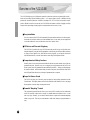 4
4
-
 5
5
-
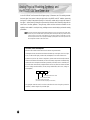 6
6
-
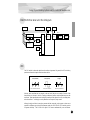 7
7
-
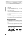 8
8
-
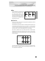 9
9
-
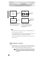 10
10
-
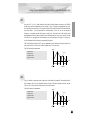 11
11
-
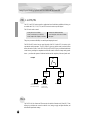 12
12
-
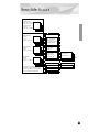 13
13
-
 14
14
-
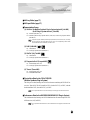 15
15
-
 16
16
-
 17
17
-
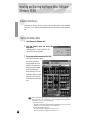 18
18
-
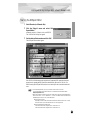 19
19
-
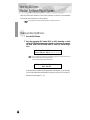 20
20
-
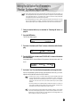 21
21
-
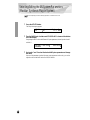 22
22
-
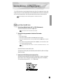 23
23
-
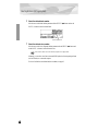 24
24
-
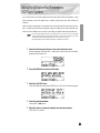 25
25
-
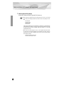 26
26
-
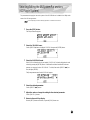 27
27
-
 28
28
-
 29
29
-
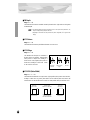 30
30
-
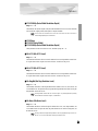 31
31
-
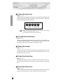 32
32
-
 33
33
-
 34
34
-
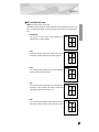 35
35
-
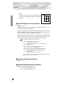 36
36
-
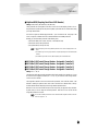 37
37
-
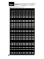 38
38
-
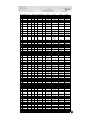 39
39
-
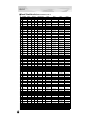 40
40
-
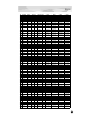 41
41
-
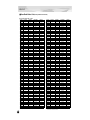 42
42
-
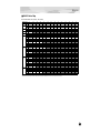 43
43
-
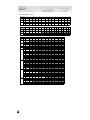 44
44
-
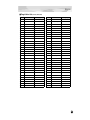 45
45
-
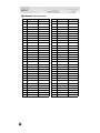 46
46
-
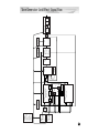 47
47
-
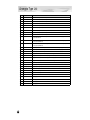 48
48
-
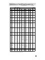 49
49
-
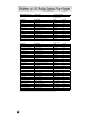 50
50
-
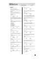 51
51
-
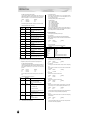 52
52
-
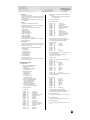 53
53
-
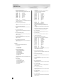 54
54
-
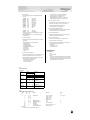 55
55
-
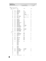 56
56
-
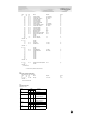 57
57
-
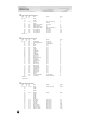 58
58
-
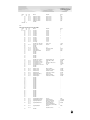 59
59
-
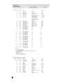 60
60
-
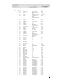 61
61
-
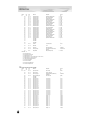 62
62
-
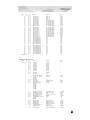 63
63
-
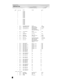 64
64
-
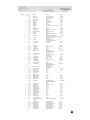 65
65
-
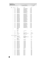 66
66
-
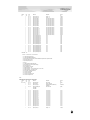 67
67
-
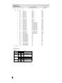 68
68
-
 69
69
-
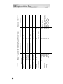 70
70
-
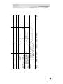 71
71
-
 72
72
-
 73
73
-
 74
74
-
 75
75
-
 76
76
-
 77
77


Yamaha PLG150 El manual del propietario
- Categoría
- Instrumentos musicales
- Tipo
- El manual del propietario
- Este manual también es adecuado para
en otros idiomas
- français: Yamaha PLG150 Le manuel du propriétaire
- italiano: Yamaha PLG150 Manuale del proprietario
- English: Yamaha PLG150 Owner's manual
- Deutsch: Yamaha PLG150 Bedienungsanleitung
- русский: Yamaha PLG150 Инструкция по применению
- Nederlands: Yamaha PLG150 de handleiding
- português: Yamaha PLG150 Manual do proprietário
- dansk: Yamaha PLG150 Brugervejledning
- polski: Yamaha PLG150 Instrukcja obsługi
- čeština: Yamaha PLG150 Návod k obsluze
- svenska: Yamaha PLG150 Bruksanvisning
- Türkçe: Yamaha PLG150 El kitabı
- suomi: Yamaha PLG150 Omistajan opas
- română: Yamaha PLG150 Manualul proprietarului
Artículos relacionados
-
Yamaha PLG150-PC El manual del propietario
-
Yamaha PLG150 El manual del propietario
-
-
-
-
Yamaha CS15D Manual de usuario
-
-
-
-