
Date Issued: 06/20/16 IS-45590-US
We’re here to help 866-558-5706
Hrs: M-F 9am to 5pm EST
CAUTION – RISK OF SHOCK –
Disconnect Power at the main circuit breaker panel or main fuse
box before starting and during the installation.
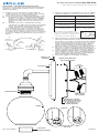
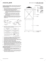
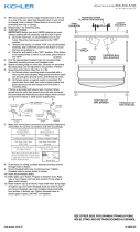
1) Attach mounting strap to outlet box with supplied screws.
NOTE: The mounting strap must be mounted with the 90°
bend with hole facing downward.
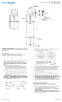
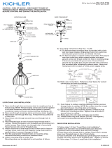
2) Grounding instructions: (See Illus. A or B)
A) On fixtures where mounting strap is provided with a
hole and two raise dimples. Wrap ground wire from
outlet box around green ground screw, and thread into
hole.
B) On fixtures where a cupped washer is provided. Put
ground wire from outlet box under cupped washer and
green ground screw and thread screw into hole in
mounting strap.
If fixture is provided with ground wire. Connect fixture
ground wire to outlet box ground wire with wire connector,
after following the above steps. Never connect ground wire
to black or white power supply wires.
3) Make wire connections. Reference chart below for correct
connections and wire accordingly.
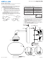
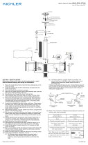
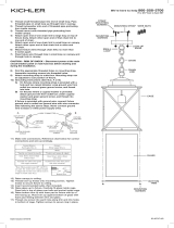
4) Raise fixture to wall slightly tilting forward to align locating
pin in bottom of canopy to hole in bottom of mounting strap.
Once locating pin is in hole of mounting strap, carefully tilt
fixture towards wall. Be careful not to pinch wires between
wall and canopy of fixture.
5) Thread mounting screws thru hole (top) in canopy into
mounting strap. Tighten mounting screws to secure fixture
to wall.
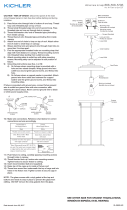
6) Raise glass to fixture carefully passing hole in glass over
socket. Thread glass retaining ring onto socket. Tighten to
secure. DO NOT over tighten.
7) Insert recommended bulb(s). (Not supplied)
GREEN GROUND
SCREW
CUPPED
WASHER
OUTLET BOX
GROUND
FIXTURE
GROUND
DIMPLES
WIRE CONNECTOR
OUTLET BOX
GROUND
GREEN GROUND
SCREW
FIXTURE
GROUND
AB
Connect Black or
Red Supply Wire to:
Connect
White Supply Wire to:
Black White
*Parallel cord (round & smooth) *Parallel cord (square & ridged)
Clear, Brown, Gold or Black
without tracer
Clear, Brown, Gold or Black
with tracer
Insulated wire (other than green)
with copper conductor
Insulated wire (other than green)
with silver conductor
*Note: When parallel wires (SPT I & SPT II)
are used. The neutral wire is square shaped
or ridged and the other wire will be round in
shape or smooth (see illus.) Neutral Wire
MOUNTING
SCREW(S)
CANOPY
SOCKET
GLASS
GLASS
RETAINING RING
OUTLET
BOX
WIRE
CONNECTOR(S)
STRAP
MOUNTING SCREW(S)
MOUNTING STRAP
NOTE: MUST BE
POSITIONED WITH
90° BEND WITH
HOLE AT THE BOTTOM
EXAMPLE
LOCATING
TAB

Date Issued: 06/20/16 IS-45590-US
Estamos aquí para ayudarle 866-558-5706
Horario: Lunes-Viernes 9am a 5pm EST (hora oficial del este)
PRECAUCIÓN – RIESGO DE DESCARGA ELÉCTRICA –
Desconecte la electricidad en el panel principal del interruptor
automático o caja principal de fusibles antes de comenzar y
durante la instalación.
1) Coloque la correa de montaje en caja de salida con
tornillos. Nota: La correa de montaje debe estar montada
con la curva de 90° con el agujero hacia abajo.
2) Instrucciones para poner a tierra: (Ver Ilustraciones A o B).
A) En artefactos donde se suministra la abrazadera de
montaje con un agujero y dos depresiones onduladas.
Envuelva el conductor de tierra de la caja de salida
alrededor del tornillo de tierra verde y atornille en el
agujero.
B) En artefactos donde se suministra una arandela
cóncava. Fije el conductor de tierra de la caja de salida
debajo de la arandela cóncava y el tornillo de tierra
verde y enrosque en la abrazadera de montaje.
Si se suministra el artefacto con conductor de tierra. Co-
necte el conductor de tierra del artefacto al conductor de
tierra de la caja de salida con conector de tierra después
de seguir los pasos anteriores. Nunca conecte el conductor
de tierra a los alambres de alimentación eléctrica negros o
blancos.
3) Haga las conexiones de los alambres. Re érase a la tabla de
abajo para realizar las conexiones correctas de los cables.
4) Suba el artefacto a la pared inclinándolo ligeramente hacia
adelante para alinear el perno de sujeción en la parte inferior
del escudete con el agujero en la parte inferior de la abraza-
dera de montaje. Una vez que el perno de sujeción esté en
el agujero de la abrazadera de montaje incline cuidadosa-
mente el artefacto hacia la pared. Tenga cuidado de no
apretar los cables entre la pared y el escudete del artefacto.
5) Enrosque los tornillos de montaje a través del agujero (ar-
riba) en el escudete en la abrazadera de montaje. Apriete los
tornillos de montaje para asegurar el artefacto a la pared.
6) Suba la pantalla de vidrio al artefacto, pasando cuidadosa-
mente el agujero en el vidrio sobre el portalámparas. En-
rosque el anillo de retención del vidrio en el portalámparas.
Apriete para asegurar. NO apriete demasiado.
7) Inserte las bombillas recomendadas (no incluido).
ARANDELA
CONCAVA
TIERRA DE LA
CAJA DE SALIDA
TORNILLO DE TIERRA,
VERDE
DEPRESIONES
TIERRA
ARTEFACTO
CONECTOR DE ALAMBRE
TIERRA DE LA
CAJA DE SALIDA
TORNILLO DE TIERRA,
VERDE
TIERRA
ARTEFACTO
AB
Conectar el alambre de
suministro negro o rojo al
Conectar el alambre de
suministro blanco al
Negro Blanco
*Cordon paralelo (redondo y liso) *Cordon paralelo (cuadrado y estriado)
Claro, marrón, amarillio o negro
sin hebra identificadora
Claro, marrón, amarillio o negro
con hebra identificadora
Alambre aislado (diferente del verde)
con conductor de cobre
Alambre aislado (diferente del
verde) con conductor de plata
*Nota: Cuando se utiliza alambre paralelo
(SPT I y SPT II). El alambre neutro es de forma
cuadrada o estriada y el otro alambre será de
forma redonda o lisa. (Vea la ilustracíón). Hilo Neutral
TORNILLO DE
MONTAJE
ESCUDETTE
PORTALÁMPARAS
VIDRIO
ANILLO DE
RETENCIÓN DEL VIDRIO
CAJA
DE SALIDA
CONECTORES
DE ALAMBRE
TORNILLO DE MONTAJE
DE LA ABRAZADERA
DE MONTAJE CORREA
NOTA: DEBE COLOCARSE
CON CURVA DE 90° CON
EL AGUJERO EN LA
PARTE INFERIOR
EJEMPLO
LOCALIZACIÓN
DE FICHA
-
 1
1
-
 2
2


en otros idiomas
- English: Kichler 45591AP Installation guide
Artículos relacionados
Otros documentos
-
 Kichler Lighting 49857BKT Manual de usuario
-
 Kichler Lighting 49689OZ Manual de usuario
-
 Kichler Lighting 49743WZCL18 Manual de usuario
-
 Kichler Lighting 43895OZ Manual de usuario
-
 Kichler Lighting 43953NI Manual de usuario
-
 Kichler Lighting 49686OZ Guía de instalación
-
 Kichler Lighting 49747WZCL18 Manual de usuario
-
 Kichler Lighting 43869BK Manual de usuario
-
 Kichler Lighting 42910PN Manual de usuario


