Vemer Set sicurezza gas GPL 3/4" Manual de usuario
- Categoría
- Iluminación de conveniencia
- Tipo
- Manual de usuario

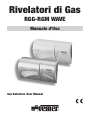
Rivelatori di Gas
RGG-RGM WAVE
Manuale d’Uso
Gas Detectors User Manual


- 3 -
Manuale Rivelatori di Gas
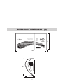
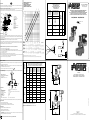
DIMENSIONI / DIMENSIONS - (A)
DIMENSIONI - (A)
RGM
Wave
Rivelatore di Gas Metano
Natural Gas Detector
Guasto
Fault
Allarme
Alarm
152
91
ON
91
44

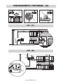
POSIZIONAMENTO / POSITIONING - (B)
- 4 -
Manuale Rivelatori di Gas
- 4 -
Manuale Rivelatori di Gas
POSIZIONAMENTO - (B)
Max 30 cm
1 ÷ 4 m
Max 30 cm
1 ÷ 4 m
Wave
Guasto
Fault
Allarme
Alarm
ON
RGM
Wave
Rivelatore di Gas Metano
Natural Gas Detector
Guasto
Fault
Allarme
Alarm
ON
RGM
Wave
Rivelatore di Gas Metano
Natural Gas Detector
Guasto
Fault
Allarme
Alarm
ON
RGM
Wave
Rivelatore di Gas Metano
Natural Gas Detector
Guasto
Fault
Allarme
Alarm
ON
Wave
Guasto
Fault
Allarme
Alarm
ON
RGG - (B1)
RGM - (B2)

- 5 -
Manuale Rivelatori di Gas
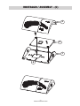
MONTAGGIO / ASSEMBLY - (C)
- 6 -
Manuale Rivelatori di Gas
MONTAGGIO - (C)
3
1
4
2

- 6 -
Manuale Rivelatori di Gas
MONTAGGIO / ASSEMBLY - (C1 a)
- 6 -
Manuale Rivelatori di Gas
MONTAGGIO - (C1 a)

- 7 -
Manuale Rivelatori di Gas
MONTAGGIO / ASSEMBLY - (C1 b)
- 7 -
Manuale Rivelatori di Gas
MONTAGGIO - (C1 b)

- 8 -
Manuale Rivelatori di Gas
MONTAGGIO / ASSEMBLY - (C2)
- 8 -
Manuale Rivelatori di Gas
MONTAGGIO - (C2)
(C3)
1
2
1
J1
BB
AA

- 9 -
Manuale Rivelatori di Gas
COLLEGAMENTI ELETTRICI / ELECTRICAL CONNECTIONS - (D)
5
5
- 9 -
Manuale Rivelatori di Gas
COLLEGAMENTI ELETTRICI - (D)
J1
BB
AA
L N
NC C NA
L N
NC C NA
L N
RGG/RGM - (D2)
~
2
3
0
V
~
5
0
H
z
NC
BB
~
2
3
0
V
~
5
0
H
z
L N
NA
RGG/RGM - (D1)
AA
5
J1
BB
AA
5

- 10 -
Manuale Rivelatori di Gas
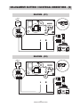
Sostituire entro
Replace within
Da compilarsi a cura dell'installatore
Fill in the form carefully
Data di
installazione
Lotto
di
fabbricazione
Locale di
installazione
Timbro
e Firma
installatore
Installation
date
Manufacturing
lot
Installation
room
Installator
signature and
stamp
- 10 -
Manuale Rivelatori di Gas
ETICHETTA DI SOSTITUZIONE / REPLACEMENT LABEL - (E)
SCHEDA DI INSTALLAZIONE / INSTALLATION CARD - (F)

Italiano
- 11 -
Manuale Rivelatori di Gas
ISTRUZIONI PER L’INSTALLAZIONE
POSIZIONAMENTO (fig. B)
• Installare in luoghi con un buon ricircolo d’aria (NON dietro a porte, tendaggi,
arredi, ...), lontano da aperture o condotti di ventilazione, al sicuro da possibili
urti o getti d’acqua.
Evitare zone particolarmente umide o con accumuli di polvere e con
temperature al di fuori di quelle consentite.
NON installare al di sopra o presso apparecchiature a gas (piccoli rilasci
all’accensione potrebbero provocare interventi intempestivi).
NON installare sopra fornelli (il vapore generato dalla cottura potrebbe
danneggiare il rivelatore)
NON installare sopra o vicino ai lavelli perché il vapore o gli spruzzi possono
causare malfunzionamenti
NON installare vicino a detergenti, solventi, vernici, lucidanti e simili perché
potrebbero sprigionare gas o sostanze che possono influenzare l’affidabilità
del dispositivo nel breve o nel lungo periodo (ad esempio: acetone,
ammoniaca, alcool, vapori siliconici);
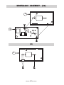
• Modello RGG (fig. B1): posizionare il rivelatore su una parete liscia ad
un’altezza max. di 30 cm dal pavimento e ad una distanza compresa
tra 1 e 4 m dall’apparecchiatura da controllare.
• Modello RGM (fig. B2): posizionare il rivelatore su una parete liscia ad
un’altezza max. di 30 cm dal soffitto e ad una distanza compresa tra 1 e 4 m
dall’apparecchiatura da controllare.
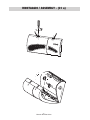
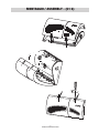
MONTAGGIO (fig. C)
• Aprire il dispositivo (fig. C1 a) e rimuovere la basetta che alloggia il circuito
elettronico (fig. C2).
• Predisporre i cavi di comando dell’elettrovalvola e i cavi di alimentazione del
rivelatore utilizzando le fessure presenti nella base del dispositivo (fig. C: )
Per il collegamento del rivelatore e della eventuale elettrovalvola utilizzare
cavi sottotraccia.
• Fissare la base del rivelatore sulla parete (fig C3) usando le viti in
dotazione.
• Riposizionare la basetta che alloggia il circuito elettronico sulla base del
rivelatore (fig. C2).
• Effettuare i collegamenti elettrici (vedi voce “COLLEGAMENTI ELETTRICI”)

Italiano
• Compilare l’etichetta (fig. E) con la data di sostituzione (data di installazione
più 4 anni) ed applicarla in posizione visibile sulla copertura del rivelatore.
• Riposizionare la copertura (fig. C1 b) ed alimentare il rivelatore.
• Compilare la scheda d’installazione (fig. F) e consegnarla, unitamente al
manuale d’uso, all’utente.
COLLEGAMENTI ELETTRICI (fig. D)
• Prima di accedere ai morsetti assicurarsi che i conduttori elettrici non siano in
tensione
• Posizionare il ponticello “J1” in funzione del tipo di elettrovalvola da
comandare:
– Elettrovalvola normalmente aperta (NA) a riarmo manuale (ponticello sui
piedini BB, fig. D1).
– Elettrovalvola normalmente chiusa (NC) a riarmo manuale (ponticello sui
piedini AA, fig. D2).
• Collegare i cavi dell’alimentazione (230 V AC) ai morsetti L-N e i cavi di
comando dell’elettrovalvola ai morsetti C-NA
NOTA: l’apparecchio diventa operativo 30 secondi dopo averlo alimentato.
FUNZIONAMENTO
• A causa dell’inevitabile decadimento delle caratteristiche chimico-fisiche
dell’elemento sensibile, il rivelatore funziona correttamente per un periodo di 4
anni a partire dalla data di alimentazione
• Indicazioni luminose
LED VERDE (ON): dispositivo alimentato
LED GIALLO (): funzionamento del sensore non corretto; in questo caso il
rivelatore va considerato guasto
LED ROSSO (): rivelatore in stato di allarme; contemporaneamente viene
attivata anche una segnalazione acustica mentre il relè commuta dopo 30 s (se
rimane la condizione di allarme).
• Stato di allarme: quando la concentrazione di gas nel locale in cui il rivelatore
è installato supera la soglia di sicurezza, viene attivata una segnalazione
acustica e luminosa (luce rossa ); il relè commuta se lo stato d’allarme
permane per più di 30 s. Le segnalazioni acustiche e luminose restano attive
finché la concentrazione di gas non rientra nei limiti di sicurezza (oppure finché
non viene tolta l’alimentazione).
• EVITARE di bagnare o urtare il rivelatore (ad esempio durante le normali
operazioni di pulizia domestica)
- 12 -
Manuale Rivelatori di Gas

Italiano
- 13 -
Manuale Rivelatori di Gas
• Il dispositivo è tarato per intervenire prima che la concentrazione di gas
raggiunga il L.I.E. (limite inferiore di esplosività: 5% per il metano, 1,8% per il
butano, principale componente del gpl), cioè prima che possa instaurarsi un
pericolo d’esplosione.
• In caso di allarme: spegnere le fiamme libere, chiudere il rubinetto del gas
o della bombola, non accendere luci, non azionare dispositivi elettrici, aprire
porte e finestre, individuare ed eliminare la causa dell’allarme. Se la causa
dell’allarme non è individuabile, abbandonare il locale ed avvisare il servizio
d’emergenza
• Soglie di allarme
RGM: 8% del L.I.E. del metano
RGG: 8% del L.I.E. del GPL
PULIZIA
Attenzione: Pulire la calotta del dispositivo con un panno morbido asciutto e
non abrasivo. Non fare uso di solventi, lucidanti e detergenti perché potrebbero
influenzare l’affidabilità del dispositivo.
ATTENZIONE:
È possibile avvertire odore di gas prima che scatti l’allarme; ciò accade
perché nel posto dove è installato il rivelatore non si è ancora raggiunta la
concentrazione critica di gas.
NORME DI RIFERIMENTO
La conformità alle Direttive Comunitarie
2006/95/CE (Bassa tensione)
2004/108/CE (Compatibilità elettromagnetica)
è dichiarata in riferimento alla seguente norma armonizzata: EN 50194.

- 14 -

English
- 15 -
Gas detectors User Manual
Index
Safety warnings Page 16
Technical specifications Page 16
Dimensions Page 3
Installation instructions Page 17
Positioning Page 17
Assembly Page 18
Electrical connections Page 18
Operation Page 18
Reference standards Page 20

English
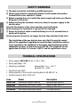
SAFETY WARNINGS
1) The device should be installed by qualified personnel
2) Power supply must be equipped by bipolar circuit breaker; Connection
terminals have cross section of 1,5mm2
3) Before removing the cover, isolate the power supply and make sure there is
NO power to the device
4) Before touching the terminals, make sure there is no power supply to the
electric wires
5) Install the detector in the correct position (see Positioning)
6) Do not power the instrument if any part of it is damaged
7) Danger of electrical shock or malfunctioning in case of manumission or
misuse of the device
8) Do not operate the device for longer than the time indicated in the label
The installation of the gas detector does not affect the need to comply
with all the regulations regarding the specifications, installation and use
of gas appliances, the ventilation of the rooms and the discharge of the
combustion product, as laid down in the UNI EN 1775 standards for the
application of article 3 of law no. 1083/71 and the legislation in force.
TECHNICAL SPECIFICATIONS
• Power supply: 230 V AC 50 Hz (-15%/+10%)
• Power absorbed: 4 VA
• Operating conditions: temperature -10 ÷ +40 °C
humidity 30 ÷ 90%
• Protection level: IP42
• Noise pressure of the acoustic warning device: 85 dBA at 1 m
• Contact capacity: 8(2) A 250 V AC
Code Model Description
VN783700 RGM WAVE Bianco Siberian Methane gas detector
VN784500 RGM WAVE Aluminium Raider Methane gas detector
VN785200 RGG WAVE Bianco Siberian LPG gas detector
VN786000 RGG WAVE Aluminium Raider LPG gas detector
- 16 -
Gas detectors User Manual

English
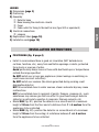
LEGEND
A) Dimensions (page 3)
B) Positioning
C) Assembly
➀ Detector base
➁ Base housing the electronic circuits
➂ Cover
➃ Cable outlet for fixing to the built-in box (type 503 or equivalent)
D) Electrical connections
➄ jumpers
E) Replacement label (page 10)
F) Installation card (page 10)
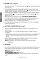
INSTALLATION INSTRUCTIONS
POSITIONING (fig. B page 4)
• Install in rooms where there is good air circulation (NOT behind doors,
curtains, furniture, etc), away from ventilation openings or ducts, protected
from shock or sources of water.
Avoid particularly damp zones or those with dust build-ups or temperatures
outside the range specified.
Do NOT install over or near gas appliances (minor leakage on switching on
could cause incorrect activation).
Do NOT install over cookers (the steam generated during cooking could
damagethe detector)
NOT to be installed close to water sources, steam and water dip may cause
malfunctions
NOT to be installed close to recipient of paints, thinners, cleaners etc.; such
substances may release gas that can affect to good functioningof detector
(detector is particularly sensitive to ammonia, thinners,solvents, etc)
• Model RGG (fig. B1): position the detector on a smooth wall at a maximum
height of 30 cm from the floor and at a distance from 1 to 4 metres from the
appliances to be controlled.
• Model RGM (fig. B2): position the detector on a smooth wall at a maximum
height of 30 cm from the ceiling) at a distance between 1 and 4 metres
from the appliances to be controlled.
- 17 -
Gas detectors User Manual

English
ASSEMBLY (fig. C page 5)
• Open the device (fig. C1 a) and remove the base that houses the electronic
circuit (fig. C2).
• Fit the solenoid valve control cables and the detector power cables in the
approprite slots in the base of the device (fig. C: ). For electrical connection
of both, detector and valve, use only in-wall wires.
• Fix the base of the detector to the wall (fig C3) using the screws supplied.
• Replace the base that houses the electronic circuit on the base of the
detector (fig. C2).
• Make the electrical connections (see “ELECTRICAL CONNECTIONS”)
• Fill in the label (fig. E) with the replacement date (date of installation plus 4
years) and apply it in a clearly visible position of the detector cover.
• Replace the cover (fig. C1 b) and power the detector.
• Fill in the installation schedule (fig. F) and hand it over to the user, together
with the user manual.
ELECTRICAL CONNECTIONS (fig. D page 9)
• Before touching the terminals, make sure there is no power supply to the
electric wires
• Position jumper “J1” in accordance with the type of solenoid valve to be
controlled:
– Normally open manual rearm solenoid valve (NO) (jumper on legs BB, fig. D1).
– Normally closed manual rearm solenoid valve (NC) (jumper on legs AA,
fig. D2).
• Connect the power supply cables (230 V AC) to the L-N terminals and the
solenoid valve control cables to the C-NA terminals
NOTE: the appliance will come into operation 30 seconds after being
switched on.
OPERATION
• Due to the inevitable deterioration of the chemical and physical characteristics
ofthe sensitive element, the detector will operate correctly for a period of 4
years from the date of activation
• Warning lamps
GREEN WARNING LAMP (ON): power on
YELLOW WARNING LAMP (): incorrect sensor operation. The detector is
faulty
- 18 -
Gas detectors User Manual

English
RED WARNING LAMP ():detector in alarm status. An acoustic warning
signal is issued at the same time and the relay switches after 30 seconds (if the
alarm condition remains).
• Alarm status: when the concentration of gas in the room where the detector
is installed exceeds the safety threshold, an acoustic and light warning signal
is activated (red warning lamp ); the relay switches if the alarm status
continues for more than 30 seconds. The acoustic and light warning signals
remain active until the gas concentration returns within the safety limits (or the
power supply is cut off).
• AVOID getting the detector wet or subjecting it to shock (during normal
household cleaning operations, for example)
• the device may control a normally open (NO) or normally closed (NC) solenoid
valve to cut off the combustible gas
• The device is calibrated to intervene before the concentration of gas reaches
the L.L.E. (lower limit of explosiveness: 5% for methane, 1.8% for butane, the
main component of LPG), that is, before the concentration creates a risk of
explosion.
• In the event of alarm:: switch off naked flames, close the gas tap or the
cylinder, do not switch on lights or, activate electrical equipment.
Open doors and windows, identify the cause of the alarm and eliminate it.
If it is not possible to identify the cause of the alarm, leave the room and call
the emergency services
• Alarm thresholds
RGM: 8% of the L.L.E. for methane
RGG: 8% of the L.L.E for LPG
CLEANING
• Attention: Clean up the cap of the device with a dry, soft, not abrasive cloth.
Don’t use dissolvent, polishing and detergents because they could influence the
reliability of the device.
CAUTION:
May happen to smell gas before alarm takes ON, this is normal; it may happen
according to where detector is located; in fact gas detector react according to
gas concentration on the room.
- 19 -
Gas detectors User Manual

English
- 20 -
Gas detectors User Manual
REFERENCE STANDARDS
Conformity to the European Community directives
2006/95/EC (Low voltage)
2004/108/EC (Electromagnetic compatibility)
is declared with reference to the following harmonised standards: EN 50194


Vemer S.p.A.
I - 32032 Feltre (BL)
Via Camp Lonc, 16
Tel +39 0439 80638
Fax +39 0439 80619
e-mail: info@vemer.it
web site: www.vemer.it
V3IS00279-060

ELETTROVALVOLA A RIARMO MANUALE NORMALMENTE APERTA PER GAS
MANUAL RESET NORMALLY OPEN SOLENOID VALVE FOR GAS
ELECTROVANNE NORMALEMENT OUVERTE A REARMÊMENT MANUEL POUR GAZ
ELEKTROVENTILE MANUALUFRÜSTUNG NORMALÖFFNUNG FUER GAS
ELECTROVÁLVULA NORMALMENTE ABIERTA A REARME MANUAL PARA GAS
M16/RMO N.A. - M16/RMOC N.A.
Las siguientes operaciones deben ser realizadas por técnicos cualifi cados.
red punto de
consumo
Dimensioni di ingombro in mm
Overall dimensions in mm
Mesures d’encombrement en mm
Raumbefarfmasse in mm
Dimensiones en mm
versione standard
standard version
version standard
Standardversion
versión estándar
con pulsante di chiusura manuale
with manual closing push button
avec bouton de fermeture manuelle
mit taste für manuelle schließung
con botón de cierre manual
Attacchi
Connections
Fixations
Anschlüsse
Conexiones
AB
M16/RMO N.A. M16/RMOC N.A.
codice
code
code
Kode
código
codice
code
code
Kode
código
RO02 RO02C DN 15 66 107
RO03 RO03C DN 20 66 107
RO04 RO04C DN 25 82 118
DN 15
1
2
3
4
DN 20
DN 25
1) metano - methane - méthane - methan - metano - 2) aria - air - air - luft - aire
3) gas di città - town gas - gaz de ville - stadtgas - gas de ciudad - 4) gpl - lpg - gaz liquide - fl üssiggas - gas líquido
DIAGRAMMA PERDITE DI CARICO
LOAD LOSS DIAGRAM
DIAGRAMME PERTES DE CHARGE
DRUCKVERLUST-DIAGRAMM
DIAGRAMMA PERDIDAS DA CARGA
Attacchi
Connections
Fixations
Anschlüsse
Conexiones
Bobine e connettori per elettrovalvole M16/RMO N.A. - M16/RMOC N.A.
Coils and connectors for M16/RMO N.A. - M16/RMOC N.A. solenoid valves
Bobines et connecteurs pour électrovannes M16/RMO N.A. - M16/RMOC N.A.
Spulen und anschlüsse für elektroventile M16/RMO N.A. - M16/RMOC N.A.
Bobinas y conectores para electroválvulas M16/RMO N.A. - M16/RMOC N.A.
Tensione
Tension
Tension
Spannung
Tensión
Codice bobina
Coil code
Code bobine
Spulenkode
Códice bobina
Timbratura bobina
Coil stamping
Timbrage bobine
Spulenstempel
Timbre bobina
Codice connettore
Connector code
Code conecteur
Anschlusskode
Códice conector
Potenza assorbita
Power absorption
Puissance absorbée
Kraftverbrauch
Potencia absorbida
DN 15 - DN 20
12 Vdc BO-0600 12 V DC CN-0010 6 VA
12 V/50 Hz BO-0800 12 V 50-60 Hz CN-0010 4 VA
24 Vdc BO-0610 24 V DC CN-0010 6 VA
24 V/50 Hz BO-0810 24 V 50-60 Hz CN-0010 4 VA
110 V/50 Hz BO-0820 110 V 50-60 Hz CN-0010 4 VA
230 V/50-60 Hz BO-0830 230V 50-60 Hz CN-0010 7 VA
DN 25
12 Vdc BO-0030 12 V DC R CN-0010 8 VA
12 V/50 Hz BO-0010 12 V DC CN-0050 20 VA
24 Vdc BO-0040 24 V DC R CN-0010 8 VA
24 V/50 Hz BO-0070 24 V 50 Hz D CN-0010 22 VA
110 V/50 Hz BO-0105 110 V 50 Hz D CN-0010 21 VA
230 V/50-60 Hz BO-0120 230 V 50 Hz V CN-0010 8 VA
Tipo connettore / Connector type / Type connecteur / Anschlusstype / Tipo conector
CN-0010 = Normale / Normal / Normal / Normal / Normal
CN-0050 (24 Vac, 12 Vac) = Raddrizzatore / Rectifi er / Reddresseur / Gleichrichter / Retifi cador
II 3G - II 3D
MADAS-09
Mod. MADAS IT/66.02
Manufactured by: MADAS s.r.l.
Via Moratello, 5/6/7 - 37045
Z.A.I. Legnago (VR) Italy
Manufactured by:
MADAS s.r.l.
Via Moratello, 5/6/7 - 37045 Z.A.I. Legnago (VR) Italy
Tel. +39 0442/23289 - Fax +39 0442/27821 - http://www.madas.it - e-mail: [email protected]
Vemer SpA
I - 32032 Feltre (BL) - Via Camp Lonc, 16
Tel. +39 0439 80638 - Fax +39 0439 80619
e-mail:info@vemer.it - web site:www.vemer.it
DESCRIPCIÓN
El funcionamiento de las electroválvulas serie M16/RMO N.A. es muy simple y por eso muy seguro. La bobina electromagnética,
si sometida a tensión, desengancha el dispositivo de cierre de la válvula que es norm. abierta. El rearme es manual para verifi car
las causas de la interceptación del gas.
Además, las versiones M16/RMOC N.A. están provistas de un botón (14) para el cierre manual de la electroválvula que puede
usarse como elemento sustitutivo de una llave de cierre manual.
Durante el normal ejercicio no hay absorción eléctrica y entonces, además del ahorro de energía, ningún órgano viene sometido
a usura.
EJEMPLO DE INSTALACIÓN
1. Electroválvula a rearme manual M16/RMO N.A.
2. Válvula de corte SM
3. Revelador gas
4. Palanca para actuación de la válvula de corte SM
1 - Botón de rearme
2 - Arandela aluminio
3 - Tubo para bobina
4 - Bobina eléctrica
5 - Conector eléctrico
6 - Núcleo móvil
7 - Obturador
8 - O-Ring de estanquidad
9 - Muelle de cierre
10 - Tapón inferior
11 - Rondana de estanquidad
12 - Órgano fi ltrante (bajo pedido)
13 - Cuerpo válvula
14 - Botón de cierre manual
(sólo en M16/RMOC N.A.)
15 - Eje central
INSTALACIÓN
La electroválvula es conforme a la Directiva 94/9/CE (denominada Directiva ATEX 100 a) como aparato del grupo II, categoría
3G y como aparato del grupo II, categoría 3D; como tal, resulta adecuada para su instalación en las zonas 2 y 22, según están
clasifi cadas en el documento adjunto I a la Directiva 99/92/CE. La electroválvula no es adecuada para su utilización en las zonas
1 y 21 y, aún menos, en las zonas 0 y 20, según se defi nen en la citada Directiva 99/92/CE.
Para determinar la califi cación y extensión de las zonas peligrosas, ver la norma EN 60079-10.
El aparato, si se instala y somete a mantenimiento respetando todas las condiciones e instrucciones técnicas referidas en el presente
documento, no da lugar a riesgos particulares: concretamente, en condiciones de funcionamiento normales, la electroválvula no
provoca la emisión a la atmósfera de sustancias infl amables con características tales que puedan provocar defl agraciones.
ATENCIÓN. Las operaciones de instalación, cableado y mantenimiento deben ser efectuadas por personal
cualifi cado.
Antes de iniciar las operaciones de instalación es necesario cerrar el gas.
Verifi car que la presión de la línea NO SEA SUPERIOR a la presión máxima indicada en la etiqueta del producto.
Normalmente deben instalarse en posición previa a los órganos de regulación, con la fl echa (que aparece en el cuerpo del
aparato) dispuesta hacia el dispositivo utilizador.
Puede ser instalada en cualquier posición.
Durante la instalación prestar atención a fi n de evitar que detritos o residuos metálicos se introduzcan en el aparato.
Verifi car que la longitud de la rosca de la tubería no sea excesiva dado que, durante el enroscado, podría provocar daños en
el cuerpo del aparato mismo. La bobina no debe utilizarse como palanca para el enroscado: utilizar para ello la respectiva
herramienta.
De todas formas, verifi car la estanqueidad del sistema una vez efectuada la instalación.
•
•
•
•
•
•
•
CONEXIONES ELÉCTRICAS
Antes de efectuar conexiones eléctricas controlar que la tensión de red corresponda a la tensión de alimentación indicada en la etiqueta
del producto.
Desconectar la alimentación antes de efectuar el cableado.
Cablear el conector mediante cable de tipo H05RN-F 3X0, 75 mm², Ø externo entre 6,2 y 8,1 mm, prestando atención a fi n de garantizar
el grado IP65 del producto.
Al efectuar el cableado del conector utilizar los respectivos terminales para cables (ver fi g. 2).
Conectar la alimentación a los bornes 1 y 2 y el cable de tierra al borne .
Para solucionar eventuales problemas o para obtener mayor información relativa a las operaciones de instalación, cableado
y mantenimiento, consúltense la dirección y los números telefónicos que se exponen en la última página.
•
•
•
•
•
CARACTERISTICAS TECNICAS
Utilizaciòn : gases combustibles de las tres familias (secos y no agresivos)
Temperatura ambiente : -15 ÷ +60 °C
Temperatura superfi cial máxima : 70 °C
Alimentación eléctrica :
12 Vdc, 12 V/50 Hz, 24 Vdc, 24 V/50 Hz, 110 V/50 Hz, 230 V/50-60 Hz
Tolerancia de tensión de alimentación : -15% ... +10%
Potencia absorbida : ver tabla
Presión máxima de trabajo : 500 mbar
Tiempo de cierre : <1 s
Grado de protecciòn : IP65
Grupo : 2
Conexiones roscadas Rp (cuerpo de latón) : (DN 15 ÷ DN 25) según EN 10226
Conforme Directiva 2004-108/CE (Compatibilidad Electromagnética); Directiva 2006/95/CE (Baja Tensión); Directiva 94/9/CE (ATEX)
REARME MANUAL
Presionar el mando de reinicialización (1) hasta obtener el enganche.
Para cerrar manualmente la electroválvula se debe presionar el botón de cierre (14).
Si está visible, la etiqueta roja situada debajo del mando de reinicialización (1) indica que la electroválvula está cerrada.
MANUTENZIONE
In ogni caso prima di effettuare verifi che interne accertarsi che:
l’apparecchio non sia alimentato elettricamente
all'interno dell’apparecchio non vi sia gas in pressione
Desenroscar el tapón inferior (10) del cuerpo válvula (13) y controlar que el obturador (7) no presente anomalías; si es necesario,
sustituir el elemento de retención en goma (11).
A continuación efectuar el montaje, realizando para ello en orden y sentido inverso las operaciones de desmontaje.
•
•
•
•
•
•
•
•
•
•
•
•
•
•
1.
2.
•
•
fi g. 1
fi g. 2 - fi g. 2 - fi g. 2 - Abb. 2 - fi g. 2
ISCOM013-0908
Le operazioni suddette devono essere eseguite esclusivamente da tecnici qualifi cati.
The above-said operations must be carried out only by qualifi ed technicians.
Les opérations susmentionnées ne doivent être exécutées que par des techniciens qualifi és.
Die oben beschriebenen Arbeitsgänge sind ausschließlich qualifi ziertem Fachpersonal halten.
DESCRIZIONE
Il principio di funzionamento delle elettrovalvole serie M16/RMO N.A. è molto semplice e per questo estremamente sicuro. La
bobina elettromagnetica, se sottoposta a tensione, sgancia il dispositivo di chiusura della valvola che è normalmente aperta.
Il riarmo è manuale per verifi care le cause dell'avvenuta intercettazione del gas.
Le versioni M16/RMOC N.A. sono dotate inoltre di un pulsante (14) per la chiusura manuale dell'elettrovalvola che può essere
usato come elemento sostitutivo di un rubinetto a chiusura manuale.
Durante il normale esercizio non c'è assorbimento elettrico e quindi, oltre al risparmio energetico, nessun organo è sottoposto
a usura.
ESEMPIO DI INSTALLAZIONE
1. Elettrovalvola a riarmo manuale M16/RMO N.A.
2. Valvola a strappo SM
3. Rivelatore gas
4. Leva comando a distanza valvola a strappo SM
rete utenza
pipe user
DESCRIPTION
The fonctioning principle of M16/RMO N.A. (normally-open manual reset solenoid valve) is very simple and extremely safe. The
coil, when under tension, releases and springs up the closing device.
The reset is manual to check the causes for gas detection.
M16/RMOC N.A. versions are equipped with a push button (14) that allows to close manually the gas substituting the manual tap
of the gas line allowing also to test at intervals the good working of the solenoid valve.
During normal conditons there is no electric absorption, and so, over the saving energy, no organ is subjected to wear and tear.
EXEMPLE D’INSTALLATION
1 - Electrovanne à réarmêment manuel M16/RMO N.A.
2 - Soupape à déchirement SM
3 - Révélateur de gaz
4 - Levier de commande à distance soupape à déchirement SM
réseau utilisateur Gasnetz Verwender
BESCHREIBUNG
Das Funktionsprinzip der Elektroventile Serie M16/RMO N.A. ist sehr einfach und deshalb überaus sicher. Wenn die elektromagnetische
Spule unter Strom steht, löst sie die Verschlussvorrichtung des Ventils aus, welches normalerweise offen ist.
Die Aufrüstung ist manuell, um die Ursachen der erfolgten Gasfeststellung prüfen zu können.
Die Versionen M16/RMOC N.A. sind zudem mit einer Taste (14) zur manuellen Schließung des Magnetventils versehen, die als
Ersatz für einen Hahn mit manueller Schließung verwendet werden kann.
Bei Normalbetrieb ist kein Stromverbrauch vorhanden, sodass ausser der Energiersparnis, kein Bestandteil unter Abnutzung
steht.
EINBAUBEISPIEL
1. Elektroventil Manualaufrüstung M16/RMO N.A.
2. Abrissventil SM
3. Gasdetektor
4. Fernsteuerungshebel Abrissventil SM
1 - Manopola di riarmo
2 - Rondella in alluminio
3 - Cannotto per bobina
4 - Bobina elettrica
5 - Connettore elettrico
6 - Nucleo mobile
7 - Otturatore
8 - O-Ring di tenuta
9 - Molla di chiusura
10 - Tappo inferiore
11 - Rondella di tenuta
12 - Organo fi ltrante (su richiesta)
13 - Corpo valvola
14 - Pulsante di chiusura manuale
(solo su M16/RMOC N.A.)
15 - Perno centrale
1 - Reset handgrip
2 - Aluminium washer
3 - Coil armature assembly
4 - Electrical coil
5 - Electrical connector
6 - Plunger
7 - Obturator
8 - Seal O-Ring
9 - Closing spring
10 - Lower cap
11 - Seal washer
12 - Filtering organ (on request)
13 - Body valve
14 - Closing manual push button
(only on M16/RMOC N.A.)
15 - Central pin
EXAMPLE OF INSTALLATION
1. M16/RMO N.A. manual reset solenoid valve
2. SM series jerk handle
3. Gas detector
3. Lever for remote SM ON/OFF valve control
1 - Manette de réarmêment
2 - Rondelle en alluminium
3 - Douille pour bobine
4 - Bobine électrique
5 - Connecteur électrique
6 - Noyau mobile
7 - Obturateur
8 - O-Ring de tenue
9 - Ressort de fermeture
10 - Bouchon inférieur
11 - Rondelle de tenue
12 - Organe fi ltrant (sur demande)
13 - Corps soupape
14 - Bouton de fermeture manuelle
(seulement sur M16/RMOC N.A.)
15 - Pivot central
1 - Aufrüstungsgriff
2 - Aluminiumring
3 - Rohr für Spule
4 - Elektrospule
5 - Elektroanschluss
6 - Beweglicher Kern
7 - Verschluss
8 - Dichtungs-O-Ring
9 - Schließfeder
10 - Untere Kappe
11 - Dichtungsring
12 - Filtervorrichtung (auf Anfrage)
13 - Ventilkörper
14 - Taste für manuelle Schließung
(nur bei M16/RMOC N.A.)
15 - Zentralstift
INSTALLAZIONE
L’elettrovalvola è conforme alla Direttiva 94/9/CE (denominata Direttiva ATEX 100 a) come apparecchio del gruppo II, categoria
3G e come apparecchio II, categoria 3D; come tale è idonea per essere installata nelle zone 2 e 22 come classifi cate nell’allegato
I alla Direttiva 99/92/CE.
L’elettrovalvola non è idonea per l’utilizzo nelle zone 1 e 21 e, a maggior ragione, nelle zone 0 e 20 come defi nite nella già citata
Direttiva 99/92/CE.
Per determinare la qualifi ca e l’estensione delle zone pericolose si veda la norma EN 60079-10.
L’apparecchio, se installato e sottoposto a manutenzione nel pieno rispetto di tutte le condizioni e istruzioni tecniche riportate
nel presente documento, non costituisce fonte di pericoli specifi ci: in particolare, in condizioni di normale funzionamento,
non è prevista, da parte dell’elettrovalvola, l’emissione in atmosfera di sostanza infi ammabile con modalità tali da originare
un’atmosfera esplosiva.
ATTENZIONE: le operazioni di installazione/cablaggio/manutenzione devono essere eseguite da personale
qualifi cato.
E’ necessario chiudere il gas prima dell’installazione.
Verifi care che la pressione di linea NON SIA SUPERIORE alla pressione massima dichiarata sull’etichetta del prodotto.
Normalmente si installano a monte degli organi di regolazione e devono essere installate con la freccia (indicata sul corpo
dell’apparecchio) rivolta verso l’utenza.
Può essere installata in qualsiasi posizione.
Durante l’installazione evitare che detriti o residui metallici penetrino all’interno dell’apparecchio.
Verifi care che la lunghezza del fi letto della tubazione non sia eccessiva per non danneggiare il corpo dell’apparecchio in fase
di avvitamento. Non usare la bobina come leva per l’avvitamento ma servirsi dell’apposito utensile.
In ogni caso dopo l’installazione verifi care la tenuta dell’impianto.
•
•
•
•
•
•
•
COLLEGAMENTI ELETTRICI
Prima di effettuare connessioni elettriche verifi care che la tensione di rete corrisponda con la tensione di alimentazione indicata
sull’etichetta del prodotto.
Scollegare l’alimentazione prima di procedere al cablaggio.
Cablare il connettore con cavo tipo H05RN-F 3X0,75mm², Ø esterno da 6,2 a 8,1mm avendo cura di assicurare il grado IP65 del
prodotto.
Nel cablare il connettore usare gli appositi terminali per cavi (vedere fi g. 2).
Collegare all’alimentazione i morsetti 1 e 2 e il cavo di terra al morsetto .
Per eventuali problemi o informazioni relativi alle operazioni di installazione/cablaggio/manutenzione vedere indirizzo
e recapiti telefonici riportati in ultima pagina.
•
•
•
•
•
CARATTERISTICHE TECNICHE
Impiego : gas non aggressivi delle tre famiglie (gas secchi)
Temperatura ambiente : -15 ÷ +60 °C
Temperatura superfi ciale max : 70 °C
Tensioni di alimentazione : 12 Vdc, 12 V/50 Hz, 24 Vdc, 24 V/50 Hz, 110 V/50 Hz, 230 V/50-60 Hz
Tolleranza su tensione di alimentazione : -15% ... +10%
Potenza assorbita : vedi tabella
Pressione massima di esercizio : 500 mbar
Tempo di chiusura : <1 s
Grado di protezione : IP65
Gruppo : 2
Attacchi fi lettati Rp (corpi ottone) : (DN 15 ÷ DN 25) secondo EN 10226
Conforme Direttiva 2004-108/CE (Compatibilità Elettromagnetica); Direttiva 2006/95/CE (Bassa Tensione); Direttiva 94/9/CE (ATEX)
RIARMO MANUALE
Premere la manopola di riarmo (1)fi no ad avvenuto aggancio.
Per chiudere manualmente l'elettrovalvola, premere il pulsante di chiusura (14).
La targhetta rossa posta sotto la manopola di riarmo (1), se visibile, indica che l'elettrovalvola è chiusa.
MANUTENZIONE
In ogni caso prima di effettuare verifi che interne accertarsi che:
l’apparecchio non sia alimentato elettricamente
all'interno dell’apparecchio non vi sia gas in pressione
Svitare il tappo inferiore (10) dal corpo valvola (13), controllare l'otturatore (7), verifi candone eventuali anomalie, se necessario
sostituire l'organo di tenuta in gomma (11).
Procedere quindi al montaggio facendo a ritroso l'operazione di smontaggio.
•
•
•
•
•
•
•
•
•
•
•
•
•
•
1.
2.
•
•
INSTALLATION
The solenoid valve is in conformity with the Directive 94/9/CE (said Directive ATEX 100 a) as device of group II, category 3G and
as device of group II, category 3D; for this reason it is suitable to be installed in the zones 2 and 22 as classifi ed in the attachment
I to the Directive 99/92/EC.
The solenoid valve is not suitable to be used in zones 1 and 21 and, all the more so, in zones 0 and 20 as classifi ed in the already
said Directive 99/92/EC.
To determine the qualifi cation and the extension of the dangerous zones, see the norm EN 60079-10.
The device, if installed and serviced respecting all the conditions and the technical instructions of this document, is not source of
specifi c dangers: in particular, during the normal working, is not forecast, by the solenoid valve, the emission in the atmosphere
of infl ammable substance in way to cause an explosive atmosphere.
WARNING: all installation/wiring/maintenance work must be carried out by skilled staff.
The gas supply must be shut off before installation.
Check that the line pressure DOES NOT EXCEED the maximum pressure stated on the product label.
They are normally installed upstream of the regulator devices and must be installed with the arrow (on the body of the device)
facing towards the user appliance.
It can be installed in any position.
During installation take care not to allow debris or scraps of metal to enter the device.
Check that the pipeline thread is not too long; overlong threads may damage the body of the device when screwed into place.
Do not use the coil for leverage when screwing into position; use the appropriate tool.
Always check that the system is gas-tight after installation.
•
•
•
•
•
•
•
ELECTRICAL CONNECTIONS
Before making electrical connections, check that the mains voltage is the same as the power supply voltage stated on the product
label.
Disconnect the power supply before wiring.
Wire the connector with H05RN-F 3X0.75mm² cable outside Ø from 6.2 a 8.1mm, taking care to ensure that the device has IP65
protection.
Use cable terminals when wiring the connector (see fi g. 2).
Connect the power supply to terminals 1 and 2 and the ground wire to terminal .
For any problems or information concerning installation/wiring/maintenance operations, see address and telephone
numbers on the back page.
•
•
•
•
•
TECHNICAL DATA
Use : not aggressive gases of the three families (dry gases)
Environment temperature : -15 ÷ +60 °C
Max. superfi cial temperature : 70 °C
Power supply voltage : 12 Vdc, 12 V/50 Hz, 24 Vdc, 24 V/50 Hz, 110 V/50 Hz, 230 V/50-60 Hz
Power supply voltage tolerance : -15% ... +10%
Power absorption : see table
Max. working pressure : 500 mbar
Closing time : < 1 s
Degree of protection : IP65
Group : 2
Threaded connections Rp (brass body) : (DN 15 ÷ DN 25) according to EN 10226
In conformity with 2004-108/EC Directive (Electromagnetic Compatibility); 2006/95/EC Directive (Low Voltage); 94/9/EC Directive (ATEX)
RIARMO MANUALE
Push the reset handgrip (1) till the hooking.
To close maually the solenoid valve, push the closing push button (14).
The red label under the manual reset (1), if visible, shows that the valve is closed.
MANUTENZIONE
In ogni caso prima di effettuare verifi che interne accertarsi che:
l’apparecchio non sia alimentato elettricamente
all'interno dell’apparecchio non vi sia gas in pressione
Unscrew the lower cap (10) from the body vale (13), then check the obturator (7) and if necessary change the rubber seal
component (11).
Reassemble doing backward the same operation of dismantling
•
•
•
•
•
•
•
•
•
•
•
•
•
•
1.
2.
•
•
DESCRIPTION
Le principe de fonctionnement des électrovannes de la série M16/RMO N.A. est très simple et pour cette raison extrèmêment
sûr. Si la bobine électromagnétique est soumise à une tension, elle déclanche le dispositif de fermeture de la soupape qui est
normalement ouverte.
Le réarmêment est manuel pour vérifi er les causes de cette apparition de gaz.
Les versions M16/RMOC N.A. sont dotées aussi d’un bouton (14) pour la fermeture manuelle de l’électrovanne qui peut être utilisé
comme élément de remplacement d’un robinet à fermeture manuelle.
En condition normale il n’y a pas d’absorbement électrique et donc, outre à une économie d’énergie, aucun composant est soumis
à l’usure.
INSTALLATION
L’électrovanne est conforme à la Directive 94/9/CE (appelée Directive ATEX 100 a) comme appareil du groupe II, catégorie 3G
et comme appareil du groupe II, catégorie 3D; comme telle elle peut être installée dans les zones 2 et 22, comme classée dans
l’annexe I de la Directive 99/92/CE.
L’électrovanne n’est pas adaptée pour l’utilisation dans les zones 1 et 21 et, encore moins, dans les zones 0 et 20 comme défi nies
dans la Directive 99/92/CE déjà citée.
Pour déterminer la qualifi cation et l’extension des zones dangereuses, se reporter à la norme EN 60079-10.
L’appareil, s’il est installé et soumis à l’entretien en respectant toutes les conditions et les instructions techniques reportées
dans ce document, ne constitue pas une source de dangers spécifi ques: en particulier, dans des conditions de fonctionnement
normal, il n’est pas prévu que l’électrovanne émette dans l’atmosphère des substances infl ammables qui pourraient provoquer
une atmosphère explosible.
ATTENTION : les opérations d’installation/câblage/entretien doivent être exécutées par du personnel qualifi é.
Fermer le gaz avant l’installation.
Vérifi er que la pression de ligne NE SOIT PAS SUPÉRIEURE à la pression maximum déclarée sur l’étiquette du produit.
Normalement on les installe en amont des organes de réglage et avec la fl èche (indiquée sur le corps de l’appareil) tournée
vers l’appareil.
Elle peut être installée dans n’importe quelle position.
Pendant l’installation, éviter que des détritus ou des résidus métalliques pénètrent dans l’appareil.
Vérifi er que le fi let de la tuyauterie ne soit pas trop long pour ne pas endommager le corps de l’appareil lors du vissage. Ne
pas utiliser la bobine comme levier pour le vissage mais se servir de l’outil approprié.
De toute façon, après l’installation vérifi er l’étanchéité de l’installation.
•
•
•
•
•
•
•
BRANCHEMENTS ÉLECTRIQUES
Avant d’effectuer les connexions électriques, vérifi er que la tension de réseau corresponde avec la tension d’alimentation indiquée sur
l’étiquette du produit.
Avant le câblage, interrompre l’alimentation.
Câbler le connecteur avec un câble type H05RN-F 3X0,75mm², Ø extérieur de 6,2 à 8,1mm en ayant soin d’assurer le degré IP65 du
produit.
Pour câbler le connecteur, utiliser les bornes spéciales pour câbles (voir fi g. 2).
Connecter à l’alimentation les bornes 1 et 2 et le câble de terre à la borne .
Pour des problèmes éventuels ou pour une demande d’informations relatives aux opérations d’installation/câblage/
entretien, voir l’adresse et les numéros de téléphone en dernière page.
•
•
•
•
•
CARACTERISTIQUES TECHNIQUES
Emploi : gaz non agressifs des trois familles (gaz secs)
Température ambiante : -15 ÷ +60 °C
Température superfi cielle maximum : 70 °C
Tension d’alimentation : 12 Vdc, 12 V/50 Hz, 24 Vdc, 24 V/50 Hz, 110 V/50 Hz, 230 V/50-60 Hz
Tolérance sur tension d’alimentation : -15% ... +10%
Puissance absorbée :
voir tableau
Pression maximale en exercice : 500 mbar
Temps de fermeture : < 1 s
Degré de protection : IP65
Groupe : 2
Fixations fi letees Rp (corps en laiton) : (DN 15 ÷ DN 25) selon EN 10226
Conforme à la Directive 2004-108/CE (Compatibilité électromagnétique); Directive 2006/95/CE (Basse Tension); Directive 94/9/CE (ATEX)
REARMÊMENT MANUEL
Appuyer sur la manette de réarmement (1) jusqu’à l’enclenchement.
Pour fermer manuellement l’électrovanne, appuyer sur le bouton de fermeture (14).
La plaquette rouge placée sous la manette de réarmement (1), si elle est visible, indique que l’électrovanne est fermée.
MANUTENTION
Avant de faire des vérifi cations internes, s’assurer:
que l’appareil n’est pas alimenté électriquement
qu’il n’y ait pas de gaz sous pression dans l’appareil
Dévisser le bouchon inférieur (10) du corps de la vanne (13), contrôler l’obturateur (7) en vérifi ant d’éventuelles anomalies; si nécessaire,
remplacer la pièce d’étanchéité en caoutchouc (11).
Passer au montage en effectuant les opérations en sens inverse du démontage.
•
•
•
•
•
•
•
•
•
•
•
•
•
•
1.
2.
•
•
EINBAU
Das Magnetventil entspricht der Richtlinie 94/9/EG (Richtlinie ATEX 100 a genannt) als Gerät der Gruppe II, Kategorie 3G und
als Gerät der Gruppe II, Kategorie 3D. Als solches eignet es sich für die Installation in den Bereichen 2 und 22, wie sie in der
Anlage I zu der Richtlinie 99/92/EG klassifi ziert sind.
Das Magnetventil eignet sich nicht für die Verwendung in den Bereichen 1 und 21 und um so mehr in den Bereichen 0 und 20,
wie sie in der bereits genannten Richtlinie 99/92/EG festgelegt sind.
Für die Bestimmung der Bezeichnung und Ausdehnung der gefährdeten Bereiche siehe Norm EN 60079-10.
Wenn das Gerät installiert und unter Einhaltung aller Bedingungen und technischen, in der vorliegenden Unterlage angegebenen
Anweisungen der Wartung unterzogen worden ist, stellt es keine besondere Gefahrenquelle dar: insbesondere ist unter normalen
Betriebsbedingungen keine Emission einer entfl ammbaren Substanz von Seiten des Magnetventils vorgesehen, wodurch eine
explosive Atmosphäre entstehen könnte.
ACHTUNG: Die Installations-, Verkabelungs- und Wartungsarbeiten müssen stets von qualifi ziertem
Fachpersonal ausgeführt werden.
Vor der Installation muss das Gas abgestellt werden.
Prüfen, ob der Leitungsdruck NICHT ÜBER dem auf dem Produktschild angegebenen Höchstdruck liegt.
Normalerweise werden die Regler vorgeschaltet installiert, wobei der Pfeil (auf dem Gehäuse des Geräts) in Richtung
Verbraucher zeigen muss.
Es kann in jeder Position eingebaut werden.
Während der Installation ist sicherzustellen, dass keine Fremdteile oder Metallrückstände in das Gerät gelangen können.
Muss überprüft werden, ob die Länge des Rohrgewindes nicht zu groß ausfällt, um das Gehäuse des Geräts beim Einschrauben
nicht zu beschädigen. Beim Einschrauben auf keinen Fall die Spule als Hebel verwenden, sondern stets das vorgesehene
Werkzeug einsetzen.
Nach der Installation ist auf jeden Fall die Dichtheit der Anlage zu überprüfen.
•
•
•
•
•
•
•
ELEKTRISCHE ANSCHLÜSSE
Vor der Ausführung von elektrischen Anschlüssen ist zu prüfen, ob die Netzspannung mit der auf dem Produktschild angegebenen
Versorgungsspannung übereinstimmt.
Vor der Verkabelung muss die Stromversorgung unterbrochen werden.
Den Verbinder mit einem Kabel des Typs H05RN-F 3X0,75mm², Außen-Ø zwischen 6,2 und 8,1 mm, versehen und hierbei entsprechende Maßnahmen
ergreifen, um die Schutzart IP65 des Produkts sicherzustellen.
Für die Verkabelung des Verbinders sind entsprechende Endstücke für Kabel zu verwenden (siehe Abb. 2).
Die Stromversorgungsleiter an die Klemmen 1 und 2 und das Erdungskabel an Klemme anschließen.
Bei eventuellen Problemen oder Informationsbedarf zu den Installations-, Verkabelungs- und Wartungsarbeiten ist die
letzte Seite mit der Anschrift und den Telefonnummern zu konsultieren.
•
•
•
•
•
TECHNISCHE EIGENSCHAFTEN
Einsatz : nicht agressive Gase der drei Familien (trockene Gase)
Raumtemperatur : -15 ÷ +60°C
Max. Oberfl ächentemperatur : 70 °C
Spannungen Stromversorgung : 12 Vdc, 12 V/50 Hz, 24 Vdc, 24 V/50 Hz, 110 V/50 Hz, 230 V/50-60 Hz
Toleranzbereich für Versorgungsspannung : -15% ... +10%
Stromverbrauch : siehe tabelle
Höchstarbeitsdruck : 500 mbar
Verschlusszeit : < 1 s
Schutzgrad : IP65
Gruppe : 2
Betresste Anschlüsse Rp (Körper aus Messing) : (DN 15 ÷ DN 25) laut EN 10226
Im Einklang mit Richtlinie 2004/108/EG (Elektromagnetische Kompatibilität); Richtlinie 2006/95/EG (Niederspannung); Richtlinie 94/9/EG (ATEX)
REARMÊMENT MANUEL
Den Bediengriff zur Rückstellung (1) bis zum erfolgten Einrasten drücken.
Zur manuellen Schließung des Magnetventils die Schließtaste (14) drücken.
Das rote Schild auf dem Bediengriff zur Rückstellung (1), falls sichtbar, zeigt an, dass das Magnetventil geschlossen ist.
MANUTENTION
Avant de faire des vérifi cations internes, s’assurer:
que l’appareil n’est pas alimenté électriquement
qu’il n’y ait pas de gaz sous pression dans l’appareil
Die untere Kappe (10) vom Ventilkörper (13) abschrauben, die Verschlussvorrichtung (7) auf eventuelle Störungen überprüfen und,
falls erforderlich, den Dichtungsteil aus Gummi (11) ersetzen.
Anschließend die Montage in umgekehrter Reihenfolge der Demontage ausführen.
•
•
•
•
•
•
•
•
•
•
•
•
•
•
1.
2.
•
•
fi g. 1
fi g. 1
fi g. 1 Abb. 1
-
 1
1
-
 2
2
-
 3
3
-
 4
4
-
 5
5
-
 6
6
-
 7
7
-
 8
8
-
 9
9
-
 10
10
-
 11
11
-
 12
12
-
 13
13
-
 14
14
-
 15
15
-
 16
16
-
 17
17
-
 18
18
-
 19
19
-
 20
20
-
 21
21
-
 22
22
-
 23
23


Vemer Set sicurezza gas GPL 3/4" Manual de usuario
- Categoría
- Iluminación de conveniencia
- Tipo
- Manual de usuario
en otros idiomas
Artículos relacionados
-
Vemer Set sicurezza gas metano 1/2" Manual de usuario
-
-
-
-
-
-
-
-
-
Otros documentos
-
ADEMCO 998mx Installation Instructions Manual
-
Marmitek SD833 Manual de usuario
-
-
Risco watchout 312PR Installation Instructions Manual
-
CAME RFC30-RTC30-RFTC30 Guía de instalación
-
DSC WS8916 Manual de usuario
-
Risco RWX34S Installation Instructions Manual
-
Vanderbilt GM730 Guía de instalación