Craftsman 37436 - Rear Propelled Bag Lawn Mower El manual del propietario
- Categoría
- Cortadoras de césped
- Tipo
- El manual del propietario
Este manual también es adecuado para

Owner's Manual
CRAFTSMAN°
ROTARY LAWN MOWER
700 Series Briggs
Power-Propelled,
22" Multi-Cut
& Stratton Engine
Electric Start
Model No.
917.374366
• EspaSol, p. 21
CAUTION'.
Read and follow all
Safety Rules and Instructions
before operating this equipment
Sears, Roebuck and Co., Hoffman Estates,
Visit our Craftsman website: www.sears.com/craftsman
IL 60179
U.S.A.

Warranty ................................................... 2
Safety Rules .......................................... 2-4
Product Specifications .............................. 4
Assembly / Pre-Operation ..................... 6-7
Operation ............................................. 8-12
Maintenance Schedule ........................... 13
Maintenance ...................................... 13-16
Service and Adjustments ................... 17-18
Storage .............................................. 18-19
Troubleshooting ................................. 19-20
Repair Parts ....................................... 40-49
Sears Service .......................... Back Cover
2-YEAR FULL WARRANTY ON CRAFTSMAN LAWN MOWER
If this Craftsman Lawn Mower fails due to manufacturer defects in material or
workmanship within two years from the date of purchase, return it to any Sears store,
Parts & Repair Center or other Craftsman outlet for free repair (or replacement if repair
proves impossible).
This warranty applies for only 90 days from the date of purchase if this Lawn Mower is
ever used for commercial or rental purposes.
This warranty does not cover:
• Expendable items that become worn during normal use, such as rotary mower
blades, blade adapters, belts, air cleaners and spark plug.
. Repairs necessary because of operator abuse or negligence, including bent
crackshafts and the failure to assemble, operate or maintain this Lawn Mower
according to all supplied product instructions.
This warranty applies only while this product is used in the United States.
This warranty gives you specific legal rights, and you may also have other rights which
vary from state to state.
Sears, Roebuck and Co., Hoffman Estates, IL 60179
IMPORTANT: This cutting machine is capable of amputating hands and feet and throw-
ing objects. Failure to observe the following safety instructions could result in serious
injury or death.
_i,Look for this symbol to point out impor-
tant safety precautions. It means
CAUTION!!! BECOME ALERT!!!
YOUR SAFETY IS INVOLVED.
_I, WARNING: In order to prevent ac-
cidental starting when setting up, trans-
porting, adjusting or making repairs,
always disconnect spark plug wire and
place wire where it cannot come in contact
with plug.
&WARNING" Engine exhaust, some of its
constituents, and certain vehicle components
contain or emit chemicals known to the State
of California to cause cancer and birth defects
or other reproductive harm.
_I,WARNING" Battery posts, terminals and
related accessories contain lead and lead
compounds, chemicals known to the State
of California to cause cancer and birth
defects or other reproductive harm. Wash
hands after handling.
_i, CAUTION: Muffler and other engine
parts become extremely hot during
operation and remain hot after engine has
stopped. To avoid severe burns on contact,
stay away from these areas.
2

I. GENERAL OPERATION
• Read, understand, and follow all
instructions on the machine and in the
manual(s) before starting. Be thoroughly
familiar with the controls and the proper
use of the machine before starting.
• Do not put hands or feet near or under
rotating parts. Keep clear of the dis-
charge opening at all times.
• Only allow responsible individuals, who
are familiar with the instructions, to oper-
ate the machine.
• Clear the area of objects such as rocks,
toys, wire, bones, sticks, etc., which
could be picked up and thrown by blade.
• Be sure the area is clear of other people
before mowing. Stop machine if anyone
enters the area.
• Do not operate the mower when bare-
foot or wearing open sandals. Always
wear substantial foot wear.
• Do not pull mower backwards unless
absolutely necessary. Always look down
and behind before and while moving
backwards.
• Never direct discharged material toward
anyone. Avoid discharging material
against a wall or obstruction. Material
may richochet back toward the opera-
tor. Stop the blade when crossing gravel
surfaces.
• Do not operate the mower without
proper guards, plates, grass catcher or
other safety protective devices in place.
• See manufacturer's instructions for
proper operation and installation of
accessories. Only use accessories ap-
proved by the manufacturer.
• Stop the blade(s) when crossing gravel
drives, walks, or roads.
• Stop the engine (motor) whenever you
leave the equipment, before cleaning the
mower or unclogging the chute.
• Shut the engine (motor) off and wait until
the blade comes to complete stop before
removing grass catcher.
• Mow only in daylight or good artificial
light.
• Do not operate the machine while under
the influence of alcohol or drugs.
• Never operate machine in wet grass.
Always be sure of your footing: keep a
firm hold on the handle; walk, never run.
• Disengage the self-propelled mech-
anism or drive clutch on mowers so
equipped before starting the engine.
• If the equipment should start to vibrate
abnormally, stop the engine (motor) and
check immediately for the cause. Vibra-
tion is generally a warning of trouble.
. Always wear safety goggles or safety
glasses with side shields when operating
mower.
Ii. SLOPE OPERATION
Slopes are a major factor related to slip &
fa!l accidents which can result in severe in-
jury. All slopes require extra caution. If you
feel uneasy on a slope, do not mow it.
DO:
• Mow across the face of slopes: never
up and down. Exercise extreme caution
when changing direction on slopes.
• Remove obstacles such as rocks, tree
limbs, etc.
• Watch for holes, ruts, or bumps. Tall
grass can hide obstacles.
DO NOT:
• Do not trim near drop-offs, ditches or
embankments. The operator could lose
footing or balance.
• Do not trim excessively steep slopes.
• Do not mow on wet grass. Reduced foot-
ing could cause slipping.
Iii. CHILDREN
Tragic accidents can occur if the operator
is not alert to the presence of children.
Children are often attracted to the machine
and the mowing activity. Never assume
that children will remain where you last
saw them.
• Keep children out of the trimming area
and under the watchful care of another
responsible adult.
• Be alert and turn machine off if children
enter the area.
• Before and while walking backwards,
look behind and down for small children.
• Never allow children to operate the ma-
chine.
• Use extra care when approaching blind
corners, shrubs, trees, or other objects
that may obscure vision.
IV. SAFE HANDLING OF GASOLINE
Use extreme care in handling gasoline.
Gasoline is extremely flammable and the
vapors are explosive.
• Extinguish all cigarettes, cigars, pipes
and other sources of ignition.
• Use only an approved container.
• Never remove gas cap or add fuel with
the engine running. Allow engine to cool
before refueling.
• Never refuel the machine indoors.
• Never store the machine or fue! contain-
er where there is an open flame, spark
or pilot light such as a water heater or on
other appliances.
3

• Never fill containers inside a vehicle, on
a truck or trailer bed with a plastic liner.
Always place containers on the ground
away from your vehicle before filling.
• Remove gas-powered equipment from
the truck or trailer and refuel it on the
ground. If this is not possible, then
refuel such equipment with a portable
container, rather than from a gasoline
dispenser nozzle.
• Keep the nozzle in contact with the rim
of the fuel tank or container opening at
all times until fueling is complete. Do
not use a nozzle lock-open device.
• If fuel is spilled on clothing, change
clothing immediately.
• Never overfill fuel tank. Replace gas
cap and tighten securely.
V. GENERAL SERVICE
• Never run a machine inside a closed
area.
Never make adjustments or repairs with
the engine (motor) running. Disconnect
the spark plug wire, and keep the wire
away from the plug to prevent accidental
starting.
• Keep nuts and bolts, especially blade
attachment bolts, tight and keep equip-
ment in good condition.
• Never tamper with safety devices. Check
their proper operation regularly.
• Keep machine free of grass, leaves, or
other debris build-up. Clean oil or fuel
spillage. Allow machine to cool before
storing.
• Stop and inspect the equipment if you
strike an object. Repair, if necessary,
before restarting.
• Never attempt to make wheel height
adjustments while the engine is running.
• Grass catcher components are subject
to wear, damage, and deterioration,
which could expose moving parts or
allow objects to be thrown. Frequently
check components and replace with
manufacturer's recommended parts,
when necessary.
• Mower blades are sharp and can cut.
Wrap the blade(s) or wear gloves, and
use extra caution when servicing them.
• Do not change the engine governor set-
ting or overspeed the engine.
• Maintain or replace safety and instruc-
tion labels, as necessary.
&WARNING: This lawn mower is equipped with an internal combustion engine and
should not be used on or near any unimproved forest-covered, brush-covered or
grass-covered land unless the engine's exhaust system is equipped with a spark
arrester meeting applicable local or state laws (if any). If a spark arrester is used, it
should be maintained in effective working order by the operator.
In the state of California the above is required by law (Section 4442 of the California
Public Resources Code). Other states may have similar laws. Federal laws apply on
federal lands. A spark arrester for the muffler is available through your nearest Sears
Parts & Repair Center (See the REPAIR PARTS section of this manual).
Serial Number:
Date of Purchase:
Gasoline Capacity / Type: 1.6 Quarts (Unleaded Regular)
Oil Type (API SG-SL): SAE 30 (above 32°F); SAE 5W-30 (below 32°F)
Oil Capacity: 20 Ounces
Spark Plug (Gap: .030") Champion RJ19HX
Blade Bolt Torque: 35-40 ft. Ibs.
• The model and serial numbers wil! be found on a decal on the rear of the lawn mower
housing. Record both serial number and date of purchase in space provided above.
4

Repair Protection Agreements
Congratulations on making a smart pur-
chase. Your new Craftsman® product is
designed and manufactured for years of
dependable operation. But like all prod-
ucts, it may require repair from time to
time. That's when having a Repair Protec-
tion Agreement can save you money and
aggravation.
Purchase a Repair Protection Agreement
now and protect yourself from unexpected
hassle and expense.
Here's what's included in the Agreement:
• Expert service by our 12,000 profe-
sional repair specialists.
• Unlimited service and no charge for
parts and labor on all covered repairs.
• Product replacement if your covered
product can't be fixed.
• Discount of 10% from regular price of
service and service-related parts not
covered by the agreement; also, 10%
off regular price of preventive mainte-
nance check.
• Fast help by phone- phone sup-
port from a Sears representative on
products requiring in-home repair, plus
convenient repair scheduling.
Once you purchase the Agreement, a
simple phone call is all that it takes for you
to schedule service. You can call anytime
day or night, or schedule a service ap-
pointment online.
Sears has over 12,000 professional repair
specialists, who have access to over 4.5
million quality parts and accessories.
That's the kind of professionalism you can
count on to help prolong the life of your
new purchase for years to come. Purchase
your Repair Protection Agreement today!
Some limitations and exclusions apply.
For prices and additional information
call 1=800=827=6655.
Sears Installation Service
For Sears professional installation of home
appliances, garage door openers, water
heaters, and other major home items, in
the U.S.A. call 1-800-4-MY-HOME®.
These accessories were available when this lawn mower was produced. They are not
shipped with your mower. They are also available at most Sears retail outlets and
service centers. Some of these accessories may not apply to your lawn mower.
LAWN MOWER PERFORMANCE
CLIPPING
DEFLECTORS
FOR
REAR DISCHARGE
LAWN MOWERS
GRASS CATCHERS
FOR
REAR DISCHARGE
LAWN MOWERS
STABILIZER
GAS
CANS
GRASS CATCHERS
FOR
SIDE DISCHARGE
LAWN MOWERS
LAWN MOWER MAINTENANCE
MUFFLERS
BELTS BLADES BLADE ADAPTERS
AIR FILTERS
WHEELS
SPARK PLUGS
ENGINE OIL
5

Read these instructions and this manual in
its entirety before you attempt to assemble
or operate your new lawn mower.
IMPORTANT: This lawn mower is shipped
WITHOUT OIL OR GASOLINE in the
engine.
Your new lawn mower has been assem-
bled at the factory with the exception of
those parts left unassembled for shipping
purposes. To ensure safe and proper
operation of your lawn mower, all parts
and hardware you assemble must be tight-
ened securely. Use the correct tools as
necessary to ensure proper tightness. All
parts such as nuts, washers, bolts, etc.,
necessary to complete the assembly have
been placed in the parts bag.
2. Remove protective padding, raise up-
per handle section into place on lower
handle and tighten both handle knobs.
3. Remove handle padding holding
operator presence control bar to upper
handle.
Your lawn mower handle can be adjusted
for your mowing comfort. Refer to "AD-
JUST HANDLE" in the Service and Adjust-
ments section of this manual.
Operator MOWING
POSITION
control bar -_b_
UP
/ //
///
///
/ Upper
handle
TO REMOVE MOWER FROM
CARTON
1. Remove loose parts included with
mower.
2. Cut down two end corners of carton
and lay end panel down flat.
3. Remove all packing materials except
padding between upper and lower
handle and padding holding operator
presence control bar to upper handle.
4. Roll lawn mower out of carton and
check carton thoroughly for additional
loose parts.
Knob
Handle
bracket
Handle
knob
Lower handle
NOW TO SET UP YOUR MOWER
TO UNFOLD HANDLE
IMPORTANT: Unfold handle carefully so
as not to pinch or damage control cables.
1. Raise handles until lower handle sec-
tion locks into place in mowing posi-
tion.
Bolt
6

TO ASSEMBLE GRASS CATCHER
1. Put grass catcher frame into grass bag
with rigid part of bag on the bottom.
Make sure the frame handle is outside
of the bag top.
2. Slip vinyl bindings over frame.
NOTE: If vinyl bindings are too stiff, hold
them in warm water for a few minutes. If
bag gets wet, let it dry before using.
Frame
Vinyl
bindings
Frame
opening
TO PREPARE BATTERY
NOTE: Your battery must be charged
before you can start your lawn mower.
1. Open battery box.
2. Connect battery charger connector
(male) to harness connector (female).
3. Plug battery charger into 110 volt A.C.
outlet.
4. Leave battery charger connected for
24 hours before starting your engine
for the first time.
5. After charging, disconnect harness
connector (female) from battery char-
ger connector (male).
Connect your battery charger to charge
battery as required.
IMPORTANT: The engine will not re-
charge your battery.
At the end of the mowing season the
battery should be charged for 48 hours to
,_otect the battery during winter storage.
CAUTION: Always disconnect the
harness connector to prevent accidental
starting when transporting or storing your
lawn mower after the season.
Battery
Harness
connector
(female)
ger
connector
(male)
Battery
box
TO INSTALL ATTACHMENTS
Your lawn mower was shipped ready to be
used as a mulcher. To convert mower to
bagging or discharging, see "TO CON-
VERT MOWER" in the Operation section
of this manual.
7

KNOW YOUR LAWN MOWER
READ THIS OWNER'S MANUAL AND ALL SAFETY RULES BEFORE OPERATING
YOUR LAWN MOWER. Compare the illustrations with your lawn mower to familiarize
yourself with the location of various controls and adjustments. Save this manual for
future reference.
These symbols may appear on your lawn mower or in literature supplied with the
product. Learn and understand their meaning.
CAUTION ENGINE ENGINE FAST SLOW CHOKE FUEL OIL DANGER, KEEP HANDS
OR WARNING ON OFF AND FEET AWAY
Operator presence control bar
Drive control lever
Key
start
switch
Handle knobs
Auxiliar_
starter
handle
Grass
Engine oil cap with dipstick
_/
Spark plug
Gasoline filler ca
Air filter
Mulcher
IMPORTANT: This lawn mower is shipped
WITHOUT OIL OR GASOLINE in the engine.
Muffler
"Housing
Wheel adjuster
(on each wheel)
MEETS CPSC SAFETY REQUIREMENTS
Sears rotary walk-behind power lawn mowers conform to the safety standards of the
American National Standards Institute and the U.S. Consumer Product Safety Com-
mission. _I,WARNING: The blade turns when the engine is running.
Operator presence control bar- must ing engine.
be held down to the handle to start the Mulcher door - allows conversion to
engine. Release to stop the engine, discharging or bagging operation.
Key start switch - used for starting engine. Drive control lever - used to engage
Auxiliary starter handle - used for start- 8 power-propelled forward motion of mower.

The operation of any lawn
SAFETVG'ASSESmower can result in foreign
objects thrown into the eyes,
which can result in severe
eye damage. Always wear
safety glasses or eye shields while oper-
ating your lawn mower or performing any
adjustments or repairs. We recommend a
standard safety glasses orwide vision safety
mask worn over spectacles.
HOW TO USE YOUR LAWN MOWER
ENGINE SPEED
Engine speed was set at the factory for
optimum performance. It is not adjustable.
DRIVE CONTROL ADJUSTMENT
Over time, the drive control system may
become "loose", resulting in decreased
speed. There is a turnbuckle on the drive
control housing to increase tension on the
drive cable. Proceed as follows:
1. Turn unit off and disconnect spark plug
wire from spark plug.
2. Rotate turnbuckle on drive control to
increase drive speed.
3. Operate mower to test drive speed.
Readjust as required.
4. If condition fails to improve after the
above steps (forward speed remains
the same), your drive belt is worn and
should be replaced.
ENGINE ZONE CONTROL
_ILCAUTION: Federal regulations require
an engine control to be installed on this
lawn mower in order to minimize the risk
of blade contact injury. Do not under
any circumstances attempt to defeat the
function of the operator control. The blade
turns when the engine is running.
• Your lawn mower is equipped with an
operator presence control bar which
requires the operator to be positioned
behind the lawn mower handle to start
and operate the lawn mower.
DRIVE CONTROL
. Self-propelling is controlled by hold-
ing the operator presence control bar
down to the handle and pulling the drive
control lever rearward to the handle.
The further toward the handle the lever
is pulled, the faster the unit will travel.
. Forward motion will stop when either
the operator presence control bar or
drive control lever are released. To stop
forward motion without stopping engine,
release the drive control lever only. Hold
operator presence control bar down
against handle to continue mowing
without self-propelling.
NOTE: If after releasing the drive control
the mower will not roll backwards, push
the mower forward slightly to disengage
drive wheels.
Operator presence control bar Drive control
lever
TO
ENGAGE DRIVE
DRIVE CONTROL
CONTROL DISENGAGED
Adjustment
turnbuckle
TO ADJUST CUTTING HEIGHT
Raise wheels for low cut and lower wheels
for high cut, adjust cutting height to suit
your requirements. Medium position is
best for most lawns.
• To change cutting height, pull up on
adjuster lever, move wheel up or down
to suit your requirements and release
adjuster lever. Be sure all wheels are in
the same setting.
NOTE: Adjuster is properly positioned
when lever inserts into hole in plate.
LEVER BACKWARD 4 il
TO LOWER MOWER
Plate
LEVER
FORWARD
9 TO RAISE MOWER

TO CONVERT MOWER
Your lawn mower was shipped ready to be
used as a mulcher. To convert to bagging
or discharging:
REAR BAGGING
• Lift rear door of the lawn mower and
place the grass catcher frame hooks
onto the grass bag brackets.
• To convert to mulching or discharging
operation, remove grass catcher and
close rear door.
- door
bag
bracket Grass
catcher
handle
Full bac
catcher indicator
frame hook window
NOTE: Rear door will remain open until
operator presence control bar is held
down to the handle.
,ACAUTION: Do NOT force rear door to
close. Serious damage to your mower
could result.
I \
\
Unlock
latch
Open
mulcher door
Discharge
deflector
\
I
I
/
SIDE DISCHARGING
• Rear door must be closed.
• Open mulcher door and install dis-
charge deflector under door as shown.
• Mower is now ready for discharging
operation.
• To convert to mulching or bagging
operation, discharge deflector must be
removed and mulcher door must be
closed and locked.
SIMPLE STEPS TO REMEMBER WHEN
CONVERTING YOUR LAWN MOWER
FOR MULCHING -
1. Rear door closed.
2. Mulcher door closed and locked.
FOR REAR BAGGING -
1. Grass catcher installed.
2. Mulcher door closed and locked.
FOR SIDE DISCHARGING -
1. Rear door closed.
2. Discharge deflector installed.
ACAUTION: Do not run your lawn mow-
er without rear door closed or approved
grass catcher in place. Never attempt to
operate the lawn mower with the rear door
removed or propped open.
10

TO EMPTY GRASS CATCHER
Empty the grass catcher when clippings
are visible in the full bag indicator window.
1. Lift up on grass catcher using the
frame handle.
2. Remove grass catcher with clippings
from under lawn mower handle.
3. Empty clippings from bag using both
frame handle and bag handle.
NOTE: Do not drag the bag when empty-
ing; it will cause unnecessary wear.
Grass
catcher
frame
Bag
handle
BEFORE STARTING ENGINE
ADD OIL
Your lawnmower is shipped without oil in
the engine. For type and grade of oil to
use, see "ENGINE" in the Maintenance
section of this manual.
A CAUTION: DO NOT overfill engine with
oil, or it will smoke heavily from the muffler
on startup.
1. Be sure lawnmower is level.
2. Remove oil dipstick from oil fill spout.
3. You receive a container of oil with the
unit. Slowly pour the entire container
down the oil fill spout into the engine.
NOTE: Initial oi! fil! requires only 18 oz.
due to residual oil in engine from the
manufacturers 100% quality testing. When
changing oi! you may need 20 oz.
4. Insert and tighten dipstick.
IMPORTANT:
• Check oil level before each use. Add oil
if needed. Fill to full line on dipstick.
• Change the oi! after every 25 hours of
operation or each season. You may
need to change the oil more often
under dusty, dirty conditions. See "TO
CHANGE ENGINE OIL" in the Mainte-
nance section of this manual.
ADD GASOLINE
Fill fuel tank to bottom of tank filler neck.
Do not overfill. Use fresh, clean, regular
unleaded gasoline with a minimum of
87 octane. Do not mix oil with gasoline.
Purchase fuel in quantities that can be
used within 30 days to assure fuel fresh-
ness.
A CAUTION: Wipe off any spilled oil or
fuel. Do not store, spill or use gasoline
near an open flame.
,A CAUTION: Alcohol blended fuels
(called gasohol or using ethanol or metha-
nol) can attract moisture which leads to
separation and formation of acids during
storage. Acidic gas can damage the fuel
system of an engine while in storage. To
avoid engine problems, the fuel system
should be emptied before storage of 30
days or longer. Empty the gas tank, start
the engine and let it run until the fuel lines
and carburetor are empty. Use fresh fuel
next season. See Storage Instructions for
additional information. Never use engine
or carburetor cleaner products in the fuel
tank or permanent damage may occur.
Engine
oil cap
Gasoline
filler cap
TO STOP ENGINE
• To stop engine, release operator pres-
ence control bar.
TO START ENGINE
NOTE: Due to protective coatings on the
engine, a small amount of smoke may be
present during the initial use of the product
and should be considered normal.
NOTE: Your engine is equipped with an
automatic choke system. No priming or
choking is required before starting.
• To start engine, hold operator presence
control bar down to the handle and turn
the start key.
IMPORTANT: Do not crank engine more
than five continous seconds between each
time you try to start. Wait 5 to 10 seconds
between each attempt.
• To start engine using the rope starter,
hold operator presence control bar
down to the handle and pull starter
handle quickly. Do not allow starter rope
to snap back.
11

MOWING TIPS
A CAUTION: Do not use de-thatcher
blade attachments on your mower. Such
attachments are hazardous, wil! damage
your mower and could void your warranty.
• Under certain conditions, such as very
tall grass, it may be necessary to raise
the height of cut to reduce pushing effort
and to keep from overloading the engine
and leaving clumps of grass clippings.
It may also be necessary to reduce
ground speed and/or run the lawn
mower over the area a second time.
• For extremely heavy cutting, reduce the
width of cut by overlapping previously
cut path and mow slowly.
• For better grass bagging and most cut-
ting conditions, the engine speed should
be set in the FAST position.
• Pores in cloth grass catchers can
become filled with dirt and dust with use
and catchers wil! collect less grass. To
prevent this, regularly hose catcher off
with water and let dry before using.
• Keep top of engine around starter clear
and clean of grass clippings and chaff.
This will help engine air flow and extend
engine life.
MULCHING MOWING TIPS
IMPORTANT: For best performance,
keep mower housing free of built-up
grass and trash. See "CLEANING" in the
Maintenance section of this manual.
• The special mulching blade will recut
the grass clippings many times and
reduce them in size so that as they fall
onto the lawn they will disperse into
the grass and not be noticed. Also, the
mulched grass will biodegrade quickly
to provide nutrients for the lawn. Always
mulch with your highest engine (blade)
speed as this will provide the best recut-
ting action of the blades.
• Avoid cutting your lawn when it is wet.
Wet grass tends to form clumps and
interferes with the mulching action. The
best time to mow your lawn is the early
afternoon. At this time the grass has
dried, yet the newly cut area will not be
exposed to direct sunlight.
• For best results, adjust the lawn mower
cutting height so that the lawn mower
cuts off only the top one-third of the
grass blades. If the lawn is overgrown it
will be necessary to raise the height of
cut to reduce pushing effort and to keep
from overloading the engine and leaving
clumps of mulched grass. For extremely
heavy grass, reduce your width of cut
by overlapping previously cut path and
mow slowly.
• Certain types of grass and grass
conditions may require that an area be
mulched a second time to completely
hide the clippings. When doing a sec-
ond cut, mow across (perpendicular) to
the first cut path.
• Change your cutting pattern from week
to week. Mow north to south one week
then change to east to west the next
week. This will help prevent matting and
graining of the lawn.
12

MAINTENANCE BEFORE AFTER EVERY
EACH EACH 10
SCHEDULE USE USE HOURS
Check for Loose Fasteners t_
,_ Clean / Inspect Grass Catcher * I/
Check Tires _1_
_ Check Drive Wheels ***
EVERY EVERY
25 HOURS 100 BEFORE
STO RAG E
OR SEASON HOURS
Clean Lawn Mower****
M Clean under Drive Cover ***
O Check Drive Belt / Pulleys ***
W Check / Sharpen / Replace Blade
_ ubrication
Clean and Recharge Battery **
Check Engine Oil level
E Change Engine Oil
N Clean Air Filter
_ Inspect Muffler
N Replace Spark Plug
I1=Replace Air Filter Paper Cartridge
Empty fuel system or add Stabilizer
i/
14
i/
i/
i/3
i/
i/
1_,2
14
I/
I/
14
t/
t/
I/
14
I/
* (if so equipped)
** Electric-Start mowers
*** Power-Propelled mowers
**** Use a scraper
to clean under deck
1 - Change more often if operating under a heavy load or in high outdoor temperatures.
2 - Service more often if operating in dirty or dusty conditions.
3 - Replace blades more often when mowing in sandy soil.
4 - Charge 48 hours at end of season.
5 - And after each 5 hours of use.
GENERAL RECOMMENDATIONS
The warranty on this lawn mower does not
cover items that have been subjected to
operator abuse or negligence. To receive
ful! value from the warranty, operator must
maintain unit as instructed in this manual.
Some adjustments wil! need to be made
periodically to properly maintain your unit.
At least once a season, check to see if
you should make any of the adjustments
described in the Service and Adjustments
section of this manual.
• At least once a year, replace the spark
plug, clean or replace air filter element
and check blade for wear. A new spark
plug and clean/new air filter element
assure proper air-fuel mixture and help
your engine run better and last longer.
• Follow the maintenance schedule in this
manual.
BEFORE EACH USE
• Check engine oil level.
• Check for loose fasteners.
LUBRICATION
Keep unit well lubricated
(See "LUBRICATION CHART").
LUBRICATION CHART
(_ Wheel
adjuster (on
each wheel)
(_ Engine oil
(_ Mulcher
door hinge
pin
(_ Rear door
hinge
(_ Handle bracket mounting pins
_ Spray lubricant
See "ENGINE" in Maintenance section.
IMPORTANT: Do not oil or grease plastic
wheel bearings. Viscous lubricants will
attract dust and dirt thatwill shorten the life of
the self-lubricating bearings. Ifyou feel they
must be lubricated, use only a dry, powdered
3graphite type lubricant sparingly.
1

LAWN MOWER
Always observe safety rules when per-
forming any maintenance.
TIRES
• Keep tires free of gasoline, oil, or insect
control chemicals which can harm rubber.
• Avoid stumps, stones, deep ruts, sharp
objects and other hazards that may
cause tire damage.
DRIVE WHEELS
Check rear drive wheels each time before
you mow to be sure they move freely.
The wheels not turning freely means trash,
grass cuttings, etc. are in the drive wheel area
and must be cleaned to free drive wheels.
If necessary to clean the drive wheels, be
sure to clean both rear wheels.
BLADE CARE
For best results, mower blade must be kept
sharp. Replace a bent or damaged blade.
A CAUTION: Use only a replacement
blade approved by the manufacturer of
your mower. Using a blade not approved
by the manufacturer of your mower is haz-
ardous, could damage your mower and
void your warranty.
TO REMOVE BLADE
1. Disconnect spark plug wire from spark
plug and place wire where it cannot
come in contact with plug.
2. Turn lawn mower on its side. Make
sure air filter and carburetor are up.
3. Use a wood block between blade and
mower housing to prevent blade from
turning when removing blade bolt.
NOTE: Protect your hands with gloves
and/or wrap blade with heavy cloth.
4. Remove blade bolt by turning counter-
clockwise.
5. Remove blade and attaching hardware
(bolt, lock washer, hardened washer).
6. Remove debris shield.
NOTE: Remove the blade adapter and
check the key inside hub of blade adapter.
The key must be in good condition to work
properly. Replace adapter if damaged.
TO REPLACE BLADE
1. Position blade adapter on engine crank-
shaft. Be sure key in adapter and crank-
shaft keyway are aligned; and that drive
belt is inside tabs of belt retainer.
2. Install debris shield.
3. Position blade on the blade adapter.
IMPORTANT: To ensure proper assembly,
center hole in blade must align with star
on blade adapter.
4. Be sure the trailing edge of blade (oppo-
site sharp edge) is up toward engine.
5. Install the blade bolt with the lock
washer and hardened washer into
blade adapter and crankshaft.
6. Use block of wood between blade and
lawn mower housing and tighten the
blade bolt, turning clockwise.
• The recommended tightening torque is
35-40 ft. Ibs.
IMPORTANT: Blade bolt is heat treated.
If bolt needs replacing, replace only with
approved bolt shown in the Repair Parts
section of this manual.
Belt
retainer
Trailing edge
Blade adapter
Hardened
Debris shield washer
Lockwasher
Blade Blade bolt
TO SHARPEN BLADE
NOTE: We do not recommend sharpening
blade - but if you do, be sure blade is bal-
anced. An unbalanced blade will cause
eventual damage to mower or engine.
• The blade can be sharpened with a file
or on a grinding wheel. Do not attempt
to sharpen while on the mower.
• To check blade balance, you will need a
5/8" diameter steel bolt, pin, ora cone bal-
ancer. (When using a cone balancer, follow
instructions supplied with balancer.)
NOTE: Do not use a nail for balancing
blade. The lobes of the center hole may
appear to be centered, but are not.
• Slide blade on to an unthreaded portion
of the steel bolt or pin and hold the
bolt or pin parallel with the ground. If
blade is balanced, it should remain in a
horizontal position. If either end of the
blade moves downward, sharpen the
heavy end until the blade is balanced.
Center hole
14
5/8" bolt or pin
Blade

GRASS CATCHER
• The grass catcher may be hosed with
water, but must be dry when used.
• Check your grass catcher often for dam-
age or deterioration. Through normal
use it will wear. If catcher needs replac-
ing, replace only with approved replace-
ment catcher shown in the Repair Parts
section of this manual. Give the lawn
mower model number when ordering.
GEAR CASE
• To keep your drive system working
properly, the gear case and area around
the drive should be kept clean and free
of trash build-up. Clean under the drive
cover twice a season.
• The gear case is filled with lubricant to
the proper level at the factory. The only
time the lubricant needs attention is if
service has been performed on the gear
case.
• If lubricant is required, use only Texaco
Starplex Premium 1 Grease, Part No.
750369. Do not substitute.
ENGINE
LUBRICATION
Use only high quality detergent oil rated with
API service classification SG-SL. Select the
oil's SAE viscosity grade according to your
expected operating temperature.
SAE VISCOSITY GRADES
F -20 0 30 32 40 60 80 100
C -30 -20 -10 0 110 20 30 40
TEMPERATURE RANGE ANTICIPATED BEFORE NEXT OIL CHANGE
NOTE: Although multi-viscosity oils
(5W30, 10W30 etc.)improve starting in
cold weather, these multi-viscosity oils will
result in increased oil consumption when
used above 32°F. Check your engine oil
level more frequently to avoid possible
engine damage from running low on oil.
Change the oil after every 25 hours of op-
eration orat least once a year if the mower
is not used for 25 hours in one year.
Check the crankcase oil level before
starting the engine and after each five (5)
hours of continuous use. Tighten oil plug
securely each time you check the oil level.
TO CHANGE ENGINE OIL
NOTE: Before tipping lawn mower to drain
oil, empty fuel tank by running engine until
fuel tank is empty.
1. Disconnect spark plug wire from spark
plug and place wire where it cannot
come in contact with plug.
.
3.
Remove engine oil cap; lay aside on a
clean surface.
Tip lawn mower on its side as shown
and drain oil into a suitable container.
Rock lawn mower back and forth to re-
move any oil trapped inside of engine.
Container
4. Wipe off any spilled oil from lawn
mower or side of engine.
5. Slowly pour oil down the oil fill spout,
stopping every few ounces to check
the oil level with the dipstick.
6. Stop adding oil when you reach the
FULL mark on the dipstick. Wait a
minute to allow oil to settle.
7. Continue adding small amounts of oil,
rechecking the dipstick until oil level
settles at FULL. DO NOT overfill, or
engine will smoke heavily from the
muffler on startup.
8. Always be sure to retighten oil dipstick
before starting engine.
9. Reconnect spark plug wire to spark
plug.
AIR FILTER
Your engine will not run properly and may
be damaged by using a dirty air filter.
Replace the air filter cartridge every 100
hours of operation or every season, which-
ever occurs first. Service air cleaner more
often under dusty conditions.
TO CLEAN AIR FILTER
1. Loosen screw and tilt cover to remove.
2. Carefully remove cartridge.
3. Clean by gently tapping on a flat sur-
face. If very dirty, replace cartridge.
,_CAUTION: Petroleum solvents, such
as kerosene, are not to be used to clean
cartridge. They may cause deterioration
of the cartridge. Do not oil cartridge. Do
not use pressurized air to clean or dry
cartridge.
4. Install cartridge, then replace cover
making sure the tabs are aligned with
the slots in the back plate. Fasten
screw securely.
15

Lip
Back plate
Cartridge
Slot
Cover
Cover tab
MUFFLER
Inspect and replace corroded muffler as it
could create a fire hazard and/or damage.
SPARK PLUG
Replace spark plug at the beginning of
each mowing season or after every 100
hours of operation, whichever occurs first.
Spark plug type and gap setting are shown
in the "PRODUCT SPECIFICATIONS"
section of this manual.
CLEANING
IMPORTANT: For best performance, keep
mower housing free of built-grass and
trash. Clean the underside of your mower
after each use.
,_CAUTION: Disconnect spark plug wire
from spark plug and place wire where it
cannot come in contact with plug.
• Clean the underside of your lawn mower
by scraping to remove build-up of grass
and trash.
• Clean engine often to keep trash from
accumulating. A clogged engine runs
hotter and shortens engine life.
• Keep finished surfaces and wheels free
of all gasoline, oil, etc.
• We do not recommend using a garden
hose to clean lawn mower unless the
electrical system, muffler, air filter and
carburetor are covered to keep water
out. Water in engine can result in short-
ened engine life.
WATER WASHOUT FEATURE
Your lawn mower is equipped with a fitting
that allows quick and easy cleaning of
the underside of the housing. To use this
feature, proceed as follows:
1. Move lawn mower to an area of cut
grass or another hard surface.
NOTE: Water, grass and other debris will
drain from beneath the mower housing
during the washout process.
2. Remove grass catcher and discharge
chute assembly from lawn mower.
3. Close mulcher door (if equipped).
4. Connect a garden hose to the fitting
where shown.
IMPORTANT: Be sure the garden hose is
not routed under the lawn mower housing
or entangled in the wheels.
5. Turn on water supply and check for
leaks at the fitting.
If no leaks are present, start engine (as
described in the Operation section of
this manual) and let engine run until the
underside of the lawn mower is clean.
• ll WARNING: Do not engage the drive
system during the washout process.
6. Shut off the engine.
7. Shut off water supply and remove
hose from fitting.
CAUTION: Do not remove hose from
fitting while engine is running. Water in
engine can result in shortened engine life.
8. Start engine (as described in the Op-
eration section of this manual) and let
engine run for a full minute to remove
excess water from mower.
Hose
Fitting
CLEAN UNDER DRIVE COVER
Clean under drive cover at least twice a
season. Scrape underside of cover with
putty knife or similar tool to remove any
build-up of trash or grass on underside of
drive cover.
16

A WARNING: To avoid serious injury, before performing any service and adjustments:
1. Release control bar and stop engine.
2. Make sure the blade and all moving parts have completely stopped.
3. Disconnect spark plug wire from spark plug and place wire where it cannot come in
contact with plug.
LAWN MOWER
TO ADJUST CUTTING HEIGHT
See "TO ADJUST CUTTING HEIGHT" in
the Operation section of this manual.
REAR DEFLECTOR
The rear deflector, attached between the rear
wheels of your mower, isprovided to minimize
the possibility that objects will be thrown out
of the rear of the mower into the operator
mowing position. If the deflector becomes
damaged, it should be replaced.
TO REMOVE DRIVE BELT
1. Remove screws securing rear baffle.
2. Turn lawn mower on its side with air
filter and carburetor down.
3. Remove rear baffle from mower.
4. Remove blade bolt, Iockwasher, hard-
ened washer and blade.
5. Remove debris shield.
6. Remove gearcase belt keeper.
7. Remove drive belt.
Rear
Gearcase
belt keeper
Belt
retainer
TO REPLACE DRIVE BELT
1. Place new drive belt on gearcase pul-
ley.
NOTE: Always use factory approved belt
to assure proper fit and long life.
2. Reinstall gearcase belt keeper. Be
sure the new drive belt is inside the
tabs of the gearcase belt keeper.
3. Position the blade adapter on the en-
gine crankshaft. Be sure key in adapter
and crankshaft keyway are aligned;
and that the new drive belt is inside the
tabs of the belt retainer.
4. Place rear baffle in mower housing.
5. Reinstall debris shield.
6. Reinstall blade.
7. Return mower to upright position.
8. Reinstall rear baffle screws.
TO ADJUST HANDLE
Your handle has three (3) height positions
- adjust to a height that suits you.
1. Remove knob and carriage bolt on one
side of the lower handle.
2. While holding handle assembly,
remove knob and carriage bolt from
opposite side, align hole in handle with
desired hole in handle bracket and
reassemble bolt and knob and tighten
securely.
3. Align opposite side of handle with
same positioning hole and secure with
bolt and knob.
Gearcase
pulley
\\i '}
Blade
adapter \
' }
Knob
Handle
bracket
Bolt
Debris
shield
Hardened
Blade
Lockwasher
Blade
bolt
17

ENGINE
ENGINE SPEED
Your engine speed has been factory set.
Do not attempt to increase engine speed
or it may result in personal injury. If you
believe that engine is running too fast or
too slow, take your mower to a Sears or
other qualified service center for repair
and adjustment.
CARBURETOR
Your carburetor is not adjustable. If your
engine does not operate properly due
to suspected carburetor problems, take
your lawn mower to a Sears or other
qualified service center for repair and/or
adjustment.
IMPORTANT: Never tamper with the
engine governor, which is factory set for
proper engine speed. Overspeeding
the engine above the factory high speed
setting can be dangerous. If you think
the engine-governed high speed needs
adjusting, contact a Sears or other
qualified service center, which has proper
equipment and experience to make any
necessary adjustments.
Immediately prepare your lawn mower for storage at the end of the season or if the unit
will not be used for 30 days or more.
LAWN MOWER
When lawn mower is to be stored for a
period of time, clean it thoroughly, remove
all dirt, grease, leaves, etc. Store in a
clean, dry area.
1. Clean entire lawn mower (See
"CLEANING" in the Maintenance sec-
tion of this manual).
2. Lubricate as shown in the Maintenance
section of this manual.
3. Be sure that all nuts, bolts, screws, and
pins are securely fastened. Inspect
moving parts for damage, breakage
and wear. Replace if necessary.
4. Touch up all rusted or chipped paint
surfaces; sand lightly before painting.
Operator
control bar
FOLD
FORWARD
FOR
STORAGE
MOWING
POSITION
Upper
handle
Handle
knob
HANDLE
You can fold your handle for storage.
1. Loosen the two (2) handle knobs on
sides of the upper handle and allow
handle to fold down to the rear.
2. Remove the two (2) handle knobs and
carriage bolts on sides of the lower handle
and pivot entire handle assembly forward
and allow it to rest on mower.
3. Reinstall knobs and carriage bolts to
lower handle / handle brackets for safe
keeping.
• When setting up your handle from
the storage position, lower handle will
require manually locking into mowing
position.
IMPORTANT: When folding the handle
for storage or transportation, be sure to
fold the handle as shown or you may dam-
age the control cables.
Knob
Handle
bracket
Lower handle
Bolt
18

ENGINE
FUEL SYSTEM
IMPORTANT: It is important to prevent
gum deposits from forming in essential fuel
system parts such as carburetor, fuel filter,
fuel hose, or tank during storage. Alcohol
blended fuels (called gasohol or using
ethanol or methanol) can attract moisture
which leads to separation and formation
of acids during storage. Acidic gas can
damage the fuel system of an engine while
in storage.
• Empty the fuel tank by starting the en-
gine and letting it run until the fuel lines
and carburetor are empty.
• Never use engine or carburetor cleaner
products in the fuel tank or permanent
damage may occur.
• Use fresh fuel next season.
NOTE: Fuel stabilizer is an acceptable
alternative in minimizing the formation of
fuel gum deposits during storage. Add
stabilizer to gasoline in fuel tank or stor-
age container. Always follow the mix ratio
found on stabilizer container. Run engine
at least 10 minutes after adding stabilizer
to allow the stabilizer to reach the car-
buretor. Do not empty the gas tank and
carburetor if using fuel stabilizer.
ENGINE OIL
Drain oil (with engine warm) and replace
with clean engine oil. (See "ENGINE" in
the Maintenance section of this manual).
CYLINDER
1. Remove spark plug.
2. Pour one ounce (29 ml) of oil through
spark plug hole into cylinder.
3. Pull starter handle slowly a few times
to distribute oil.
4. Replace with new spark plug.
BATTERY
Disconnect the battery from the engine
connector and charge battery 48 hours.
OTHER
• Do not store gasoline from one season
to another.
• Replace your gasoline can if your can
starts to rust. Rust and/or dirt in your
gasoline will cause problems.
• If possible, store your unit indoors and
cover it to protect it from dust and dirt.
• Cover your unit with a suitable protec-
tive cover that does not retain moisture.
Do not use plastic. Plastic cannot
breathe, which allows condensation to
form and will cause your unit to rust.
IMPORTANT: Never cover mower while
engine and exhaust areas are still warm.
,I_CAUTION: Never store the lawn
mower with gasoline in the tank inside a
building where fumes may reach an open
flame or spark. Allow the engine to cool
before storing in any enclosure.
TROUBLESHOOTING =See appropriate section in manual unless directed
to a Sears Parts & Repair Center.
PROBLEM CAUSE
Does not start 1. Dirty air filter.
2. Out of fue!.
3. Stale fuel.
4. Water in fuel.
5. Spark plug wire disconnected.
6. Bad spark plug.
7. Loose blade or broken
blade adapter.
8. Control bar in released
position.
9. Control bar defective.
10. Fuel valve lever (if so
equipped) in OFF position.
11. Weak battery (if equipped).
12. Disconnected battery
connector (if equipped).
19
CORRECTION
1. Clean/replace air filter.
2. Fill fuel tank.
3. Empty fuel tank and refill tank
with fresh, clean gasoline.
4. Empty fue! tank and refill tank
with fresh, clean gasoline.
5. Connect wire to plug.
6. Replace spark plug.
7. Tighten blade bolt or
replace blade adapter.
8. Depress control bar to
handle.
9. Replace control bar.
10.Turn fuel valve lever
to the ON position.
11. Charge battery.
12. Connect battery to engine.

TROUBLESHOOTING =See appropriate section in manual unless directed
to a Sears Parts & Repair Center.
CAUSEPROBLEM
Loss of power
Poor cut -
ui3eveR
Excessive
vibration
Starter rope
hard to pull
Grass catcher
not filling
(if so equipped)
Hard to push
Loss of drive
or slowing of
drive speed
1. Rear of mower housing or
blade dragging in grass.
2. Cutting too much grass.
3. Dirty air filter.
4. Buildup of grass, leaves,
and trash under mower.
5. Too much oil in engine.
6. Walking speed too fast.
1. Worn, bent or loose blade.
2. Wheel heights uneven.
3. Buildup of grass, leaves
and trash under mower.
1. Worn, bent or loose blade.
2. Bent engine crankshaft.
.
.
3.
4.
Engine flywheel brake is on
when control bar is released.
Bent engine crankshaft.
Blade adapter broken.
Blade dragging in grass.
1. Cutting height too low.
2. Lift on blade worn off.
3. Catcher not venting air.
1. Grass is too high or wheel
height is too low.
2. Rear of mower housing or
blade dragging in grass.
3. Grass catcher too ful!.
4. Handle height position not
right for you.
1. Belt wear.
2. Belt off of pulley.
3. Drive cable worn or broken.
4. "Loose" drive control system.
CORRECTION
1. Raise cutting height.
2. Raise cutting height.
3. Clean/replace air filter.
4. Clean underside of mower
housing.
5. Check oi! level.
6. Cut at slower walking speed.
1. Replace blade. Tighten
blade bolt.
2. Set all wheels at same
height.
3. Clean underside of
mower housing.
1. Replace blade. Tighten
blade bolt.
2. Contact a Sears or other
qualified service center.
1. Depress control bar to
upper handle before
pulling the starter rope.
2. Contact a Sears or other
qualified service center.
3. Replace blade adapter.
4. Move lawn mower to cut
grass or to hard surface.
1. Raise cutting height.
2. Replace blade.
3. Clean grass catcher.
1. Raise cutting height.
2. Raise rear of mower housing
one (1) setting higher.
3. Empty grass catcher.
4. Adjust handle height to suit.
1. Check/replace drive belt.
2. Check/reinstall drive belt.
3. Replace drive cable.
4. Adjust drive control.
NEED MORE HELP?
You'll find the answer and more on managemyhome.com - for free!
• Find this and all your other product manuals online.
• Get answers from our team of home experts.
• Get a personalized maintenance plan for your home.
• Find information and tools to help with home projects.
20
brought to you by Sears

Garantia ......................................................... 21
Reglas de Seguridad ................................ 21-23
Especificaciones del Producto ....................... 23
Montaje / Pre-Operaci6n .......................... 25-26
Operaci6n ................................................. 27-31
Programa de Mantenimiento ......................... 32
Mantenimiento .......................................... 32-35
Servicio y Adjustes ................................... 36-37
Almacenamiento ....................................... 37-38
Identificaci6n de problemas ...................... 38-39
Partes de repuesto .................................. 40-49
Servicio Sears .................................. Contratapa
GARANTiA TOTAL DE LA CORTADORA DE ClaSPED CRAFTSMAN POR 2 ANOS
Siesta Segadora Craftsman Ilega a presentar algOn desperfecto por defectos de materiales
o fabricaci6n durante un plazo de dos a_os a partir de la fecha de compra, Ilevela de vuelta a
cualquiera de las tiendas Sears, al Centro de Repuestos y Reparaci6n, o a otro comercio donde se
vendan los equipos Craftsman, a efectos de que se la reparen sin costo (o bien se la reemplacen,
en caso que no sea posible repararla).
Siesta Segadora Ilega a ser utilizada con fines comerciales o arrendada, la presente garantia tendra
vigencia por s61o 90 dias a partir de la fecha de compra.
La presente garantia no cubre:
• Aquellas piezas fungibles que se desgastan por el uso normal, tales como las cuchillas rotatorias
de la cortadora, los adaptadores de las cuchillas, las correas, los filtros de aire y las bujias.
• Aquellas reparaciones que haya que hacer debido a mal uso o negligencia por parte del operador,
incluidos el arbol del cigQefial torcido u omisiones relativas al armado, manejo o mantenimieno de
la Segadora en un todo de acuerdo alas instrucciones provistas con el equipo.
La presente garantia se aplicara solamente en tanto el articulo sea usado en los Estados Unidos.
Esta garantia le otorga a usted derechos legales especificos; puede que usted tenga, ademas, otros
derechos, los cuales varian de estado a estado.
Sears, Roebuck and Co., Hoffman Estates, IL 60179
IMPORTANTE: Esta maquina cortadaora es capaz de amputar las manos y los manos y los pies y
de lanzar objetos. Si no se observan las instrucciones de seguridad siguientes se pueden producir
lesiones graves o la muerte.
,_Busque este simbolo que sefiala las precau-
ciones de seguridad de importancia. Quiere
decir - ii iATENCION!!! i iiESTE ALERTO!!!
SU SEGURIDAD ESTA COMPROMETIDA.
_I, ADVERTENCIA: Siempre desconecte el
alambre de la bujia y p6ngalo donde no pueda
entrar en contacto con la bujia, para evitar el
arranque por accidente, durante la preparaci6n,
el transporte, el ajuste o cuando se hacen
reparaciones.
_I, ADVERTENCIA: Los bornes, terminales y
accesorios relativos de la bateria contienen
plomo o compuestos de plomo, productos
quimicos conocidos en el Estado de California
como causa de cancer y defectos al nacimiento
u otros dafios reproductivos. Lavar las manos
despues de manipularlos.
_I, PRECAUCI6N: El tubo de escape del motor,
algunos de sus constituyentes y algunos com-
ponentes del vehiculo contienen o desprenden
productos quimicos conocidos en el Estado de
California como causa de cancer y defectos al
nacimiento u otros dafios reproductivos.
_I, PRECAUCl6N: El silenciador y otras piezas
del motor Ilegan a sre extremadamente calien-
tes durante la operaci6n y siguen siendo calf
entes despues de que el motor haya parado.
Para evitar quemaduras severas, permanezca
lejos de estas areas.
21

I. OPERACION
• Antes de empezar, debe familiarizarse
completamente con los controles y el uso
correcto de la maquina. Para esto, debe leer
y comprender todas las instrucciones que
aparecen en la maquina y en los manuales
de operaci6n.
• No ponga las manos o los pies cerca o
debajo de las partes rotatorias. Mantengase
siempre lejos de la abertura de la descarga.
• Permita que solamente las personas re-
sponsables que esten familiarizadas con las
instrucciones operen la maquina.
• Despeje el area de objetos tales como pie-
dras, juguetes, alambres, huesos, palos, etc.
que pueden ser recogidos y lanzados por las
cuchillas.
• Aseg_rese que el area no se hallen per-
sonas, antes de segar. Pare la maquina si
alguien entra en el area.
• No opere la maquina sin zapatos o con
sandalias abiertas. P6ngase siempre zapatos
s61idos.
• No tire de la segadora hacia atras a menos
que sea absolutamente necesario. Mire
siempre hacia abajo y hacia detras antes y
mientras que se mueve hacia atras.
• Nunca dirigir el material descargado hacia
las personas. Evitar descargar material
contra paredes o barreras. El material puede
retornar al operador. Para la cuchilla cuando
se pasa por superficies de grava.
• No opere la segadora sin los respectivos
resguardos, las placas, el recogedor de
cesped u otros aditamentos dise ados para
su protecci6n y seguridad.
• Refierase alas instrucciones del fabricante
para el funcionamiento e instalaci6n de
accesorios. Use Qnicamente accesorios
aprobados pot el fabricante.
• Detenga la cuchilla o las cuchillas cuando
cruce pot calzadas, calles o caminos de
grava.
• Parar el motor cada vez que se abandona el
aparato, antes de limpiar la segadora o de
remover residuos del tubo.
• Apagar el motor y esperar hasta que las
cuchillas esten completamente paradas
antes de remover el receptor de hierba.
• Segar solamente con luz del dia o con una
buena luz artificial.
• No opere la maquina bajo la influencia del
alcohol o de las drogas.
Nunca opere la maquina cuando la hierba
este mojada. AsegQrese siempre de tener
buena tracci6n en sus pies; mantenga el
mango firmemente y camine; nunca corra.
Desconectar el mecanismo de propulsi6n
aut6noma o el embrague de transmisi6n en
las segadoras que Io tienen antes de poner
en marcha el motor.
Si el equipo empezara a vibrar de una
manera anormal, pare el motor y revise de
inmediato para averiguar la causa. General-
mente la vibraci6n suele indicar que existe
alguna averia.
• Siempre use gafas de seguridad o anteojos
con protecci6n lateral cuando opere la sega-
dora.
II. OPERACION SOBRE LAS CUESTAS
Los accidentes ocurren con mas frecuencia en
las cuestas. Estos accidentes ocurren debido a
resbaladas o caidas, las cuales pueden resultar
en graves lesiones. Operar la recortadora en
cuestas requiere mayor concentraci6n. Si se
siente inseguro en una cuesta, no la recorte.
HACER:
• Puede recortar a traves de la superficie de
la cuesta, nunca hacia arriba y hacia abajo.
Proceda con extrema precauci6n cuando
cambie de direcci6n en las cuestas.
• Renueva todos los objetos extrafios, tales
como guijarros, ramas, etc.
• Debe prestar atenci6n a hoyos, baches o
protuberancias. Recuerde que la hierba alta
puede esconder obstaculos.
NO HACER:
• No recorte cerca de pendientes, zanjas o
terraplenes. El operador puede perder la
tracci6n en los pies o el equilibrio.
• No recorte cuestas demasiado inclinadas.
• No recorte en hierba mojada. La reducci6n
en la tracci6n de la pisada puede causar
resbalones.
III. NINOS
Se pueden producir accidentes tragicos si el
operador no presta atenci6n a la presencia
de los nifios. A menudo, los nifios se sienten
atraidos por la maquina y por la actividad de
la siega. Nunca suponga que los nifios van a
permanecer en el mismo lugar donde los vio
por _ltima vez.
• Mantenga a los nifios alejados del area de
la siega y bajo el cuidado estricto de otra
persona adulta responsable.
• Este alerta y apague la maquina si hay nifios
que entran al area.
• Antes y cuando este retrocediendo, mire
hacia atras y hacia abajo para verificar si hay
nifios pequefios.
• Nunca permita que los nifios operen la ma-
quina.
• Tenga un cuidado extra cuando se acerque
a esquinas donde no hay visibilidad, a los
arbustos, arboles u otros objetos que pueden
interferir con su linea de visidn.
IV. MANEJO SEGURO DE GASOLINA
Usar mucha atencidn cuando se maneja gaso-
lina. La gasolina es extremamente inflamable y
los vapores son explosivos.
• Apagar todos los cigarrillos, cigarros, pipas y
otras fuentes de ignicidn.
• Usar solo un contenedor apropiado.
• Nunca quitar el tap6n de la gasolina o afiadir
carburante con el motor en marcha. Esperar
que el motor se enfrie antes de repostar la
gasolina.
22

• Nunca repostar la maquina al interior de un
local.
• Nunca guardar la maquina o el contenedor
de gasolina donde hay una llama abierta,
chispa o luz piloto como una caldera u otros
dispositivos.
• Nunca Ilenar contenedores en un vehiculo,
en un cami6n o caravana con un forro de
plastico. Colocar siempre los contenedores
en el suelo lejos de su vehiculo antes de
Ilenar.
• Quitar equipos que funcionan con gasolina
del cami6n o caravana y repostar en el suelo.
Si esto no es posible, repostar dicho equipo
con un contenedor portatil, mas bien que con
una tobera de gasolina.
• Mantener la tobera en contacto con el bordo
del depdsito de carburante o de la apertura
del contenedor siempre hasta terminar el
abastecimiento. No usar un dispositivo de
cierre-apertura de la tobera.
• Si el carburante cae en la ropa que se Ileva,
cambiarsela inmediatamente.
• Nunca Ilenar en exceso el depdsito de
carburante. Colocar el tapdn de la gasolina y
apretar de modo seguro.
V. SERVIClO
• Nunca haga funcionar una maquina dentro
de un area cerrada.
• Nunca haga ajustes o reparaciones mientras
el motor este en marcha. Desconecte el
cable de la bujia, y mantengalo a cierta
distancia de esta para prevenir un arranque
accidental.
* Mantenga las tuercas y los pernos, espe-
cialmente los pernos del accesorio de la
cuchilla, apretados y mantenga el equipo en
buenas condiciones.
* Nunca manipule de forma indebida los
dispositivos de seguridad. Controle regular-
mente su funcionamiento correcto.
* Mantenga la maquina libre de hierba, hojas
u otras acumulaciones de desperdicio.
Limpie los derrames de aceite o combustible.
Permita que la maquina se enfrie antes de
almacenarla.
* Pare e inspeccione el equipo si le pega a un
objeto. Reparelo, si es necesario, antes de
hacerlo arrancar.
* En ningQn caso hay que regular la altura de
las ruedas mientras el motor esta en marcha.
* Los componentes del receptor de la hierba
van sujetos a desgaste, da_os y deterioro,
que pueden exponer las partes en mov-
imiento o permitir que objetos sean dispara-
dos. Controlar frecuentemente y cuando sea
necesario sustituir con partes aconsejadas
pot el fabricante.
* Las cuchillas de la segadora estan afiladas
y pueden cortar. Cubrir las hojas o Ilevar
guantes, y utilizar precauciones especiales
cuando se efectQa mantenimiento sobre las
mismas.
* No cambie el ajuste del regulador del motor
ni exceda su velocidad.
* Mantener o sustituir las etiquetas de
seguridad e instrucciones, cuando sea
necesario.
_I, ADVERTENClA: Este segadora viene equipado con un motor de combusti6n interna y no se
debe usar sobre, o cerca, de un terreno no desarrollado cubierto de bosques, de arbustos o de
cesped, o menos que el sistema de escape del motor venga equipado con un amortiguador de
chispas que cumpla con las leyes locales o estatales (si existen). Si se usa un amortiguador de
chispas, el operador debe mantenerlo en condiciones de trabajo eficientes.
En el estado de California, la ley exige Io anterior (Secci6n 4442 del "California Public Re-
sources Code"). Otros estados pueden contar con otras leyes parecidas. Las leyes federales
se aplican en la tierras federales. Su centro de Servicio mas cercano tiene disponible amor-
tiguadores de chispas para el silenciador (Vea la secci6n de PARTES DE REPUESTO en el
manual Ingles del due_o).
NOmero de Serie:
Fecha de Compra:
Capacidad y Tipo de Gasolina: 1.6 Cuartos (Regular sin PIomo)
Tipo de Aceite (API SG-SL): SAE 30 (Sobre 32°F); SAE 5W-30 (Debajo 32°F)
Capacidad de Aceite: 20 Onzas
Bujia (Abertura: .030") Champion RJ19HX
Torsi6n del Perno de la Cuchilla: 35-40 ft. Ibs.
• El nQmero del nodelo y el de serie se encuentran en la calcomania adjunta a la parte trasera
de la caja de la segadora. Debe registrar tanto el nQmero de serie come la fecha de compra y
mantengalos en un lugar seguro para refencia en el futuro.
23

Acuerdos de Protecci6n para la Reparaci6n
Congratulaciones por su buena compra. Su
nuevo producto Craftsman® esta diseSado
y fabricado para funcionar de modo liable pot
muchos a_os. Pero como todos los productos,
puede necesitar alguna reparaci6n de tanto
en tanto. En este caso tenet un Acuerdo de
Proteccidn para la Reparacidn puede hacerles
ahorrar dinero y fastidios.
Compre ahora un Acuerdo de Proteccidn para
la Reparacidn y protegese de molestias y gas-
tos inesperados.
Un Acuerdo incluye los puntos siguientes:
• Servicio experto de nuestros 12.000 espe-
cialistas profesionales en la reparaci6n.
• Servicio ilimitado sin cargo alguno para
las partes y la mano de obra sobre todas las
reparaciones garantizadas.
• Sustituci6n de! producto si su producto
garantizado no puede set arreglado.
• Descuento del 10% sobre el precio cot=
riente del servicio y de las partes relativas al
servicio no cubiertas pot el acuerdo; tambien
el 10% menos sobre el precio corriente de
un control de mantenimiento preventivo.
• Ayuda rapida por telefono - soporte tele=
f6nico por parte de un representante Sears
sobre productos que requieren un arreglo en
casa, y ademas una programaci6n sobre los
a reglos mas convenientes.
Cuando se ha comprado el Acuerdo, basta con
una Ilamada telef6nica para programar el servi-
cio. Puede Ilamar cuando quiera, dia y noche o
fijar en linea una cita para obtener el servicio.
Sears tiene mas de 12.000 especialistas
profesionales en la reparaci6n, que tienen
acceso a mas de 4.5 millones de partes y
accesorios de calidad. Este es el tipo de
profesionalidad con que puede contar para
ayudar a alargar la vida del producto que acaba
de comprar, pot muchos aSos. iCompre hoy su
Acuerdo de Protecci6n para la Reparaci6n!
Se aplican algunas limitaciones y e×clu-
siones. Para conocer los precios y tenet
mas information, Ilame al 1=800=827=6655.
Servicio de Instalaci6n Sears
Para la instalacidn profesiona/ Sears de
aparatos de casa, puertas de garaje,
calentadores de agua y otros importantes
articulos para la casa, en U.S.A. Ilamar a
1=800=4=MY=HOME®.
Estos accesorios estaban disponibles cuando se produjo la segadora. No son facilitados junto al
cortacesped. Tambien estan disponibles en la mayoda de las tiendas de Sears yen los centros
de servicio. Algunos de estos accesorios tal vez no se apliquen a su segadora.
RENDIMIENTO DE LA SEGADORA
DESVIADOR
DE RECORTES
PARA SEGADORAS
CON DESCARGA
TRASERA
RECOREDOR
PARA
SEGADORAS
CON DESCARGA
TRASERA
ESTABILI-
ZADORES
ENVASES
E GASOLINA
RECOREDOR
PARA
SEGADORAS
CON DESCARGA
LATERAL
MANTENIMIENTO DE LA SEGADORA
SILENCIADORES
CORREAS CUCHILLAS
ADAPTADORES
DE CUCHILLA
FILTROS DE AIRE
RUEDAS
BUJiAS
ACEITE
DEL MOTOR
24

Lea estas instrucciones y este manual comple-
tamente antes de tratar de montar u operar su
segadora nueva.
IMPORTANTE: Este cortacesped viene SIN
ACEITE O GASOLINA en el motor.
Su segadora nueva ha sido montada en la
fabrica con la excepci6n de aquellas partes que
se dejaron sin montar por razones de envio.
Todas las partes como las tuercas, las arande-
las, los pernos, etc., que son necesarias para
completar el montaje han sido colocadas en la
bolsa de partes. Para asegurarse que su sega-
dora funcione en forma segura y adecuada,
todas las partes y los articulos de ferreteda que
se monten tienen que set apretados segura-
mente. Use las herramientas correctas, como
sea necesario, para asegurar que se aprieten
adecuadamente.
PARA REMOVER LA SEGADORA DE
LA CAJA DE CARTON
1. Remueva las partes sueltas que se incluyen
con la segadora.
2. Corte las dos esquinas de los extremos
de la caja de cart6n y tienda el panel del
extremo piano.
3. Remueva todo el material de empaque, ex-
cepto la curia entre el mango superior y 61
inferior, y la curia que sujeta la barra de los
control que exige la presencia del operador
junto con el mango superior.
4. Haga rodar la segadora hacia afuera de la
caja de cart6n y revisela cuidadosamente
para verificar si todavia quedan partes
sueltas adicionales.
COMO PREPARAR SU SEGADORA
PARA DESDOBLAR EL MANGO
IMPORTANTE: Despliegue el mango con
mucho cuidado para no pellizcar o dafiar los
cables de control.
1. Levante los mangos hasta que la secci6n
del mango inferior se asegure en su lugar,
en la posici6n para segar.
2. Remueva la curia protectora, levante la sec-
ci6n del mango superior hasta su lugar en
el mango inferior, y apriete ambas manillas
del mango.
3. Remueva la curia del mango que sujeta la
barra de los control que exige la presencia
del operador junto con el mango superior.
El mango de la segadora puede ajustarse
segQn le acomode para segar. Refierase a
"AJUSTE DEL MANGO" en la secci6n de
Servicio y Ajustes de este manual.
Barra de POSICION
que exige la PARA
presencia det SEGAR
operador
LEVANTAR
/ //
///
Mango
superior
Manitla det
mango
Mango Inferior
Soporte
de mango
Perno
25

PARA MONTAR EL RECOGEDOR DE
CE_SPED
I. Ponga elbastidordelrecogedorde cesped
en labolsadelcesped con laparterigida
de labolsaen laparteinferior.AsegQrese
que el mango del bastidor este en el exte-
rior de la parte superior de la bolsa.
2. Deslice los sujetadores de vinilo sobre el
bastidor.
AVlSO: Si los sujetadores de vinilo estan muy
duros, metalos en agua caliente por algunos
minutos. Si se moja la bolsa, dejela que se
seque antes de usarla.
Sujetadore,,
de vinito
Abertura
det bastidor
PARA PREPARAR LA BATERiA
AVISO: Su bateda tiene que estar cargada an-
tes de que pueda hacer arrancar su segadora.
1. Abrir la caja de la bated&
2. Conecte el conector del cargador de la
bateda (macho) al conector de la arnCs
(hembra).
3. Enchufe el cargador de la bateda dentro del
enchufe de 110 volt C.A.
4. Deje el cargador de la bateria conectado
pot 24 horas antes de hacer arrancar su
motor pot la primera vez.
5. Despues de cargar, desconecte el conec-
tor de la ames (hembra) al conector de la
cargador de la bateda (macho).
Conecte su cargador de bateda para cargarla
segOn sea necesafio.
IMPORTANTE: El motor no cargara una
bated&
AI final de la temporada de siega, la bateda
se debe cargar por 48 horas para protegerla
durante el periodo de almacenamiento en el
invierno.
_I, PRECAUCI6N: Siempre desconecte el
conector de la arnes para evitar el arranque por
accidente al transportar o guardar su segadora
despues de la temporada.
Cargador de la bateria_.
Conector
della ames
(hembra)
Caja de la
bateria
PARA INSTALAR LOS ACCESORIOS
Su segadora fue enviada lista para usarse
como una acolchadora de capa vegetal. Para
convertirla de modo que pueda ensacar o
descargar, refierase a "PARA CONVERTIR LA
SEGADORA" en la secci6n de Operaci6n de
este manual.
26

FAMILIARICESE CON SU SEGADORA
LEA ESTE MANUAL DEL DUENO Y LAS REGLAS DE SEGURIDAD ANTES DE OPARAR SU
SEGADORA. Compare las ilustraciones con su segadora para familiarizarse con la ubicaci6n de
los diversos controles y ajustes. Guarde este manual para referencia en el futuro.
Estos simbolos pueden apareser sobre su segadora o en la literatura proporcionada con el
producto. Aprenda y comprenda sus significados.
ATTENCION O MOTOR MOTOR R,_,PIDO LENTO ESTRANGU COM- ACEITE PELIGRO, GUARDE LAS
ADVERTENClA ENCENDIDO APAGADO LACION BUSTIBLE MANOS Y LOS PIES LEJOS
Barra de control que exige la
presencia del operador
Palanca de control de la impulsi6n
Interru
de arranque
de Ilave
Manillas del mango
Cord6n
arrancador j
auxiliar
Recogedor Bujia
de ces
Tapa del deposito de
aciete del motor con varilla
indicadora de nivel
Tapa del deposito
de la gasolina
Filtro de
Puerta de la acolchadora
Silenciador
Caja
_justador de
la rueda (en
IMPORTANTE: Este cortacesped viene cada rueda)
SIN ACEITE O GASOLINA en motor•
CUMPLE CON LOS REQUISITOS DE SEGURIDAD DE LA CPSC
Las segadoras a motor, que se conducen desde la parte de atras, rotatorias, Sears, cumplen con
los estandares de seguridad de l American National Standards Institute y de la U.S. Consumer
Product Safety Commission• _B_PRECAUCION: La cuchilla gira cuando el motor esta funcionando.
Barra de control que e×ige la presencia del
operador - tiene que sujetarse abajo, junto
con el mango, para hacer arrancar el motor•
Su¢ltela para parar el motor•
Palanca de control de la impulsion - se usa
para enganchar la segadora para movimiento
hacia adelante impulsada a motor•
Puerta de la acolchadora - permite la conver=
si6n para la operaci6n de descarga o ensacado.
Interruptor de arranque de Ilave - se usa
para hacer arrancar el motor•
Cord6n arrancador au×iliar - se usa para
hacer arrancar el motor•
27

La operaci6n de cualquier
segadora puede hacer que
salten objetos extrafios dentro de
sus ojos, Io que puede producir
dafios graves en estos. Siempre
use anteojos de seguridad o protecci6n para
los ojos mientras opere su segadora o cuando
haga ajustes o reparaciones. Recomendamos
gafas o una mascara de segufidad de visi6n
amplia de seguridad usada sobre las gafas.
SEGURIDAD
COMO USAR SU SEGADORA
VELOCIDAD DEL MOTOR
La velocidad del motor se estableci6 en la fa=
brica para un rendimiento 6ptimo. La velocidad
no se puede ajustar.
NTROL DE ZONA DEL MOTOR
PRECAUCION: Las regulaciones federales
exigen que se instale un control para el motor
en esta segadora para reducir a un minimo el
riesgo de lesionarse debido al contacto con la
cuchilla. Pot ningQn motivo trate de eliminar
la funci6n del control del operador. La cuchilla
gira cuando el motor esta funcionando.
• Su segadora viene equipada con una barra
de controles que exigen la presencia del
operador, Io que requiere que el operador
este detras del mango de la segadora para
hacerla arrancar y operarla.
CONTROL DE LA IMPULSI6N
• La autopropulsidn se controla manteniendo
la palanca de mando operador presente
abajo hacia el mango y tirando la palanca de
accionamiento atras hacia el mango. Cuanto
mas lejos se tira la palanca hacia el mango,
mas rapida ira la unidad.
• El movimiento hacia adelante se detiene
cuando sea la palanca de mando operador
presente o la palanca de accionamiento se
sueltan. Para detener el movimiento hacia
adelante sin apagar el motor, soltar s61o
la palanca de accionamiento. Mantener la
palanca de mando operador presente abajo
contra el mango para continuar a cortar sin
autopropulsi6n.
AVlSO: Si despues haber desenganchado
de la palanca de control, la segadora no roda
hacia atras, empuje la segadora un poco hacia
adelante para desenganchar las ruedas de la
impulsi6n.
Barra de control que _xige ta presencia det operador
PARA
ENGANCHAR EL
CONTROL DE LA
IMPULSION
Control de
la impulsi6n
CONTROL DE LA
IMPULSION
DESENGANCHADO
AJUSTE DEL MANDO
Ocasionalmente, el sistema de mando puede
"aflojarse", provocando una disminuci6n de la
velocidad. Hay un torniquete en la sede del
mando para apretar la tensi6n del cable. Pro-
ceder de la siguiente manera:
1. Apagar la unidad y desconectar el cable de
bujia de la bujia.
2. Vuelta el torniquete para aumentar la velo-
cidad del mecanismo.
3. Opere la segadora para probar la velo-
cidad del mecanismo. Reajuste segQn Io
requerido.
4. Si las condiciones no mejoran despues
de los pasos descritos (la velocidad hacia
adelante queda la misma), la correa de
transmisi6n esta desgastada y tiene que ser
sustituida.
Torniquete ajuste
PARA AJUSTAR LA ALTURA DE CORTE
Levante las ruedas para el corte bajo y baje
las ruedas para el corte alto, ajuste la altura de
corte para que se acomode a sus requisitos. La
posici6n del medio es la mejor para la mayoria
de los cespedes.
• Para cambiar la altura de corte, levante encen-
dido la palanca del ajustador hacia la rueda,
mueva la rueda hacia arriba o hacia abajo de
modo que se acomode a sus requisitos y lan-
zamiento la palanca. AsegOrese que todas las
ruedas queden igualmente ajustadas.
AVlSO: El ajustador esta correctamente colo-
cado cuando la palanca estan insertadas en el
agujero del placa.
PALANCAHACIA _
ATRA.SPARABAJAR
EL CORTAC¢SPED
Palanca de aj
Placa
HACIA
ADELANTE
PARA
LEVANTAR EL
28CORTAC¢SPED

PARA CONVERTIR LA SEGADORA
Su segadora fue enviada lista para usarse como
acolchadora de capa vegetal. Para convertirla a
una operaci6n de ensacado o de descarga:
SEGADORAS CON DESCARGA TRASERA
• Levantar la puerta trasera de cortacesped
y colocar los ganchos del armaz6n de la
recolectora de hierba en los soporte del
recogedor de cesped.
• Para pasar a la operaci6n de acolchamiento,
remover la recolectora de hierba y cerrar la
puerta trasera.
Puerta trasera
Soporte det
recogedor de cesped
Mango det
bastidor del
-._recogedorde
-_.. cesped
I \
\
Abierto la
contra ta I
descarga I
Desviador
de ta descarga
Gancho
det bastidor de bolsa
det recogedor ltena
AVISO: Le puerta trasara seguira siendo abi-
erto hasta la barra de control que exige la pres-
encia del operador se mantiene a la mango.
• ILPRECAUClON: No fuerce la puerta trasera
para cerrarse. El dafio grave a su segadora
podia resultar.
\
SEGADORAS CON DESCARGA LATERAL
• La puerta trasera tiene que estar cerrada.
• Abra la protecci6n contra la descarga y
instale el desviador de contra la descarga
debajo de la protecci6n como se muestra.
• La segadora esta lista para la operaci6n de
la descarga.
• Para convertir a la operaci6n de ensacado
o de descarga, el desviador de la descarga
debe set removido y la protecci6n contra la
descarga debe estar cerrada y trabado.
PASOS SIMPLES DE RECORDAR
CUANDO CONVIERTA SU SEGADORA
PARA ACOLCHAMIENTO -
1. La puerta trasera cerrada.
2. La protecci6n contra la descarga cerrada y
trabado.
PARA ENSACAMIENTO TRASERO -
1. Recogedor del cesped instalado.
2. La protecci6n contra la descarga cerrada y
trabado.
PARA DESCARGA LATERAL-
1. La puerta trasera cerrada.
2. La desviador de la descarga instalada.
,A PRECAUCION: No haga funcionar su
segadora sin la placa de la acolchadora sin
el recogedor cesped aprobados en su lugar.
Nunca trate de operar la segadora cuando se
halla removido la puerta trasera o cuando se
ha removido a puerta trasera o cuando esta un
poco abierta.
29

PARA VACIAR EL RECOGEDOR DE
CO:SPED
Vacie el recogedor de cesped cuando los
recortes son visibles en la ventana Ilena del
indicador de bolsa liana.
1. Levante el recogedor de cesped usando el
mango del bastidor.
2. Remueva el recogedor de cesped, con los
recortes, de debajo del mango de la sega-
dora.
3. Vacie los recortes de la bolsa.
AVlSO: No arrastre la bolsa cuando la vacie;
se producira un desgaste innecesario.
Mango det
bastidor
del
edor
de cesped
ANTES DE HACER
ARRANCAR EL MOTOR
AGREGUE ACEITE
Su segadora fue enviada sin aceite en el motor.
Para el tipo y el grado del aceite a utilizar, vea
el "MOTOR" en la secci6n del Mantenimiento
de este manual.
,_PRECAUCl6N: NO sobrellene el motor con
aceite, o fumara pesa demante del silenciador
cuando Io valla a arrancar.
1. AsegOrese que la segadora este nivelada.
2. Remueva la varila medidora de aceite del
tubo de desarga de aceite.
3. Usted recibe un envase de aceite con la
unidad. Vierta lentamente el envase entero
de aceite en el tubo de relleno del motor.
AVlSO: El terraplen inicial del aceite requiere
solamente 18 onzas debido al aceite residual
en el motor de la prueba de calidad de 100%
del fabricante. AI cambiar el aceite puede
necesitar 20 onzas.
4. Inserte y apriete la varilla medidora de
aceite.
IMPORTANTE:
• Revise el nivel del aceite antes de cada uso.
Agregue aceite si es necesario. Llene hasta
la linea de Ileno en la varilla medidora de
nivel.
• Cambie el aceite despues de 25 horas de
operaci6n o una vez por temporada. Puede
necesitar cambiar el aceite mas a menudo
cuando las condiciones son polvorosas o su-
cias. Vea "PARA CAMBIAR EL ACEITE DEL
MOTOR" en la seccion de Mantenimiento de
este manual.
AGREGUE GASOLINA
• Llene el estanque de combustible hasta la
parte inferior del cuello de relleno del es-
tanque de gasolina. No Io Ilene demasiado.
Use gasolina regular, sin plomo, nueva y lim-
pia con el minimo de 87 octanos. No mezcle
el aceite con la gasolina. Para asegurar
que la gasolina utilizada sea fresca compre
estanques los cuales puedan ser utilizados
durante los primeros 30 dias.
PRECAUClON: Limpie el aceite o el
combustible derramado. No almacene, derrame
o use gasolina cerca de una llama expuesta.
_I_,PRECAUCI(DN: Los combustibles
mezclados con alcohol (conocidos como
gasohol, o el uso de etanol o metanol) pueden
atraer la humedad, la que conduce a la
separaci6n y formaci6n de acidos durante el
almacenamiento. La gasolina acidica puede
dafiar el sistema del combustible de un motor
durante el almacenamiento. Para evitar los
problemas con el motor, se debe vaciar el
sistema del combustible antes de guardarlo
por un periodo de 30 dias o mas. Vacie el
estanque del combustible, haga arrancar el
motor y hagalo funcionar hasta que las lineas
del combustible y el carburador queden vacios.
La pr6xima temporada use combustible nuevo.
Vea las Instrucciones Para El Almacenamiento
para mas informaci6n. Nunca use productos de
limpieza para el motor o para el carburador en
el estanque del combustible pues se pueden
producir dafios permanentes.
•Tapa del
deposito de
aceite
Tapa del
rellenador
de
gasolina
PARA PARAR EL MOTOR
• Para parar el motor, suelte la barra de con-
troles que exigen la presencia del operador.
PARA HACER ARRANCAR EL MOTOR
AVISO: Debido a las capas protectoras del mo-
tor, una cantidad pequefia de humo puede es-
tar presente durante el uso inicial del producto
y se debe considerar normal.
1. Para hacer arrancar un motor fdo, empuje
el cebador tres (3) veces antes de tratarlo.
Empuje firmemente. Este paso normal-
mente no es necesario cuando se hace
arrancar un motor que ya ha estado funcio-
nando pot unos cuantos minutos.
2. Sujete la barra de control que exige la
presencia del operador abajo en el mango y
gire la Ilave para el arranque electrico en el
sentido de las manillas del reloj para hacer
arrancar el motor.3O

IMPORTANTE: No haga arrancar el motor
mas de 5 segundos continuados. Espere 5 a 10
segundos entre cada vez que trate de hacerlo
arrancar.
• Para comenzar el motor sandio el arrancador
de soga, siga los pasos de arriba. Cambie el
uso del Ilave de arranque con el arrancador
de soga. No permita que la soga vuelva a su
posici6n inicial demasiado brusca mente.
AVISO: En climas mas frios puede que sea
necesario repetir los pasos del cebado. En cli-
mas mas calurosos el cebar demasiado puede
producir el ahogo y el motor no va a arrancar.
Si se ahoga el motor espere unos cuantos
minutos antes de tratar de hacerlo arrancar y
no repita los pasos del cebado.
ONSEJOS PARA SEGAR
PRECAUClON: No utilizar dispositivos anti-
paja de la hoja en la segadora ya que estos
accesorios son peligrosos, pueden dafiar su
segadora y anular su garantia.
• Bajo ciertas condiciones, tal como cesped
muy alto, puede ser necesario el elevar
la altura del corte para reducir el esfuerzo
necesario para empujar la segadora y para
evitar sobrecargar el motor, dejando mon-
tones de recortes de cesped. Puede que sea
necesario reducir la velocidad del recorrido
y/o haga funcionar la segadora sobre el area
por segunda vez.
• Para un corte muy pesado, reduzca el ancho
del corte pasando parcialmente por encima
del lugar anteriormente cortado y siegue
lentamente.
• Para un mejor ensacado del cesped y para la
mayoria de las condiciones de corte, la velo-
cidad del motor debe ajustarse a la posici6n
de R,_,PIDO.
• Los poros en los recogedores de cesped de
tela pueden Ilenarse con mugre y polvo con
el uso y los recogedores recaudaran menos
cesped. Para evitar este, rocie el recogedor
con la manguera de agua regularmente y
dejelo secarse antes de usarlo.
• Mantenga la parte superior del motor, alred-
edor del arrancador, despejada y sin recortes
de cesped y paja. Esto ayudara el flujo del
aire del motor y extendera su duraci6n.
CONSEJOS PARA SEGAR Y ACOL-
CHAR
IMPORTANTE: Para obtener el mejor
rendimiento mantenga la caja de la segadora
sin acumulacion de cesped y basura. Vea
"LIMPIEZA" en la seccion de Mantenimento de
este manual.
• La cuchilla acolchadora especial va a volver
a cortar los recortes de cesped muchas
veces, y los reduce en tamafio, de modo que
si se caen en el cesped se van a dispesar
entre este y no se van a notar. Tambien, el
cesped acolchado se va a deshacer rapidam-
ente entregando substancias nutritivas para
el cesped. Siempre acolche con la velocidad
del motor (cuchilla) mas alta, pues asi se
obtendra la mejor acci6n de recorte de las
cuchillas.
• Evite cortar el cesped cuando este mojado.
El cesped mojado tiende a format montones
e interfiere con la acci6n de acolchado.
La mejor hora para segar el cesped es
temprano en la tarde. A esa hora este se ha
secado y el area recien cortada no quedara
expuesta al sol directo.
• Para obtener los mejores resultados, ajuste
la altura del corte de la segadora de modo
que esta corte solamente el tercio superior
de las hojas de cesped. En el caso de que el
cesped haya crecido demasiado, puede set
necesario el elevar la altura del corte para
reducir el esfuerzo necesario para empujar la
segadora y para evitar sobrecargar el motor,
dejando montones de recortes de cesped.
Para un cesped muy pesado, reduzca el an-
cho del corte pasando pot encima del lugar
anteriormente cortado y siegue lentamente.
MAX 1/3
• Ciertos tipos de cesped y sus condiciones
pueden exigir que un area tenga que ser
acolchada pot segunda vez para esconder
completamente los recortes. Cuando se haga
el segundo corte, siegue atravesado (en
forma perpendicular) a la pasada del primer
corte.
• Cambie su patr6n de corte de semana a
semana. Siegue de norte a sur una semana
y luego cambie de este a oeste la pr6xima
semana. Esto evitara que el cesped se
enrede y cambie de direcci6n.
31

PROGRAMA DE ANTES DESPUES CADA CADA CADA ANTES DEL
MANTENIMIENTO DE CADA DE CADA 10 25 HORAS O 100 ALMACE-
USO USO HORAS TEMPORADA HORAS NAMIENTO
Revisar si hay Sujetadores Sueltos _1_ _1_
S Limpiar/Inspeccionar el Recogedor de Cesped * I_
E Controlar los NeumAticos I_
Controlar las Ruedas Motrices *** if
Limpiar la Segadora .... !_
_ Limpiar debajo la Cubierta de la Transmisi6n *** I_
Revisar las Correas y las Poleas Impulsadas *** _1_3
Revisar / Afilar / Cambiar la Cuchilla
Lubricacion
i/
i/
Limpiar / Recargar la Bateria ** if I_
Revisar el nivel del Aceite
M Cambiar el Aceite del motor 1_,2
Limpiar el Filtro de Aire _
Inspeccionar el Silenciador
O Cambiar la Bujia t_
Cambiar el Cartucho de Papel del Filtro de Aire t_
Vaciar el sistema del carburante
o afiadir un estabilizador de carburante.
iv'
, (si viene equipado) 1 - Cambiar mgts a menudo cuando se opere bajo carga pesada o en ambientes con altas temperaturas.
** Segadoras con Arranque Electrico 2 - Dar servicio mAs a menudo cuando se opere en condiciones sucias o polvorosas.
*** Segadoras con Poder Propulsor 3 - Cambie las cuchillas m__sa menudo cuando siegue en terreno arenoso.
**** Utilizar una rasqueta para limpiar 4 - Cargar por 48 horas al fin de la temporada.
debajo de la cubierta del cortacesped 5 - Y despu_s de 5 horas de funcionamiento.
RECOMENDACIONES GENERALES
La garant{a de esta segadora no cubre los
articulos que han estado sujetos al abuso o a
la negligencia del operador. Para recibir todo
el valor de la garantia, el operador tiene que
mantener la segadora segQn las instrucciones
descritas en este manual.
Hay algunos ajustes que se tienen que hacer
en forma peri6dica para poder mantener su
unidad adecuadamente.
AI menos una vez cada estaci6n comprobar
si es necesario efectuar los ajustes descritos
en las secciones de Servicio y Ajustes de este
manual.
• Una vez al a_o, cambie la bujia, limpie o
cambie el elemento del filtro de aire y revise
si la cuchilla esta desgastada. Una bujia
nueva y un elemento del filtro de aire limpio/
nuevo aseguran la mezcla de aire=com-
bustible adecuada y ayudan a que su motor
funcione mejor y que dure mas.
• Siga el programa de mantenimiento en este
manual.
TABLA DE LUBRICACION
(_ Ajustador
de la rueda
(_) Aceite del
motor
(_ Bisagra
la puerta
de la acol-
chadora
(_ Bisagra
de la
puerta
traser
(_) Clavija de montaje del puntal del mango
ANTES DE CADA USO
• Revise el nivel del aceite del motor.
• Revise si hay sujetadores sueltos.
LUBRICACION
Mantenga la unidad bien lubricada
(vea la "TABLA DE LUBRICAClON").
(_ Rocie el lubricante
(_) Vea "MOTOR" en la seccion de Mantenimiento
IMPORTANTE: No aceite o engrase los roda-
mientos de la rueda de plastico. Los lubricantes
viscosos atearan polvo y mugre, Io acortara la
duracion de los rodamientos autolubricantes. Si
cree que tienen que lubricarse, use Iosamente
un lubricante tipo crafito, de polvo seco, en
forma moderada.
32

SEGADORA
Siempre observe las reglas de seguridad cu-
ando haga el mantenimiento.
LLANTAS
• Mantenga las Ilantas sin gasolina, aceite o
substancias quimicas para control de insec-
tos que pueden dafiar la goma.
• Evite los tocones, las piedras, las grietas pro-
fundas, los objetos afilados y otros peligros
que pueden dafiar alas Ilantas.
RUEDAS DE IMPULSI6N
Revise las ruedas de impulsi6n traseras cada
vez antes de segar, para asegurarse de que se
mueven libremente. Si las ruedas no giran li-
bremente quiere decir que hay basura, recortes
de cesped, etc. en el area de las ruedas de
impulsi6n y tienen que limpiarse para liberarlas.
Es necesario limpiar las ruedas de impulsi6n;
revise ambas ruedas traseras.
CUIDADO DE LA CUCHILLA
Para obtener los mejores resultados, la cuchilla
de la segadora tienen que mantenerse afilada.
mbie la cuchilla doblada o dafiada.
PRECAUClON: Usar solamente la cuchilla
de repuesto aprobada por el fabricante de su
segadora. Usar una cuchilla no aprobada por
el fabricante de su segadora es peligroso, pu-
erie dafiar su segadora y anular su garantia.
PARA REMOVER LA CUCHILLA
1. Desconecte el alambre de la bujia y p6ngalo en
donde no pueda entrar en contacto con esta.
2. Haga descansar la segadora en su lado.
AsegQrese que el filtro de aire y que el car-
burador queden mirando hacia arriba.
3. Use un bloque de madera entre la cuchilla
y la caja de la segadora para evitar que la
cuchilla gire cuando se le quite el perno.
AVlSO: Proteja sus manos con guantes y/o
envuelva la cuchilla con una tela gruesa.
4. Remueva el perno de la cuchilla girandolo en
el sentido contrario en que giran las manillas
del reloj.
5. Remueva la cuchilla y los articulos de fer-
reteria adjuntadores (el perno, la arandela de
seguridad y la arandela endurecida).
6. Remueva el cubierta de la caja de engranajes.
AVlSO: Remueva el adaptador de la cuchilla y
revise el cubo interior de la ranura del adaptador
de la cuchilla. La ranura tiene que estar en buenas
condiciones para que funcione en forma adec-
uada. Cambie el adaptador si esta dafiado.
PARA CAMBIAR LA CUCHILLA
1. Ponga el adaptador de la cuchilla en el
ciguefial del motor. AsegQrese que la ranura
del adaptador y que el chavetero del cigue-
fial esten alineados. Asegurarse de que la
correa se halle al interior de los dispositivos
de retenci6n de correa.
2. Instale el cubierta de la caja de engranajes.
3. Ponga la cuchilla en el adaptador.
IMPORTANTE: Para asegurar la instalacion ap-
ropiada, posicione el agujero central de la cuchilla
con la estrella del conjunto del adaptador.
4. AsegQrese de que el borde de salida de la
cuchilla (opuesto al borde afilado) este hacia
arriba hacia el motor. 33
5. Instale el perno de la cuchilla con la arandela
de seguridad y la arandela endurecida en el
adaptador de la cuchilla y el ciguefial.
6. Use un bloque de madera entre la cuchilla
y la caja de la segadora y apriete el perno
de la cuchilla girandolo en el sentido en que
giran las manillas del reloj.
• La torsi6n para apretar recomendada es de
35 - 40 pies libras.
IMPORTANTE: El perno de la cuchilla es
tratado a calo. Si es necesario sustituir los
pernos, sustituirlos s61o con pernos aprobados
mostrados en la secci6n Partes de Reparaci6n
de este manual.
-\\ fl "_ ° _ .................- J
Chavetero'\\ \ [L _"_ ................ JJ
det ciguenal \,,_.._ / , j j
Ranura _]1 ' /if j
de correa
Borde de salida
Adaptador de la
Cubierta de ta caja
de engranajes
Arandeta
endurecida
Arandeta de
guridad
la
cuchitla
PARA AFILAR LA CUCHILLA
AVlSO: No recomendamos el afilar la cuchilla
- pero si Io hace, asegQrese de que quede bal-
anceada. Una cuchilla que no esta balanceada
va a producir eventualmente dafio en la sega-
dora o en el motor.
• La cuchilla puede afilarse con una lima o en
una rueda rectificadora. No trate de afilarla
mientras se encuentra en la segadora.
• Para revisar el balance de la cuchilla, va a
necesitar un perno de acero de 5/8", una
clavija o un balanceador c6nico. (Cuando se
use un balanceador c6nico, siga las instruc-
ciones que vienen con el balanceador.)
AVlSO: No use un elavo para balancear la
cuchilla. Los 16bulos del agujero central pueden
aparecer como centrados, pero no Io estan.
• Deslice la cuchilla en una parte no roscada
del perno de acero o clavija y sujete el perno
o la clavija paralelo al suelo. Si la cuchilla esta
balanceada, debe permanecer en la posici6n
horizontal. Si cualquiera de los extremos de la
cuchilla se mueva hacia abajo, afile el extremo
pesado hasta que esta quede balanceada.
Agujero central
Perno de la
cuchitta de 5/8"
Cuchitta

RECOGEDOR DE CO:SPED
• El recogedor de cesped puede ser rociado
con el agua de la manguera pero tiene que
estar seco cuando se vaya a usar.
• Revise su recogedor de cesped a menudo
para verificar siesta dafiado o deteriorado.
Se va a ctesgastar con el uso normal. Si se
necesita cambiar el recogedor, cambielo
solamente por uno que sea aprobado por el
fabricante. De el nQmero del modelo de la
segadora cuando Io ordene.
CAJA DE ENGRANAJES
• Para mantener el sistema de impulsi6n
funcionando en forma adecuada, la caja de
engranajes y el area alrededor de la impulsi6n
tienen que mantenerse limpias y sin acumu-
laci6n de basura. Limpie debajo de la cubierta
de la impulsi6n dos veces por temporada.
• La caja de engranajes se Ilena con lubricante
hasta el nivel adecuado en la fabrica. La
Qnica vez que el lubricante necesita atenci6n
es cuancto se le ha prestado servicio a la
caja de engranajes.
• Si se necesita lubricante, use solamente
Grasa Texaco Starplex Premium 1, Parte No.
750369. No use substitutos.
MOTOR
LUBRICACION
Use solamente aceite de detergente de alta
calidad clasificado con la ciasificaci6n SG-SL
de servicio API. Seleccione la calidad de visco-
sidad SAE segQn su temperatura de operaci6n
esperada.
CALIDADES DE VISCOSIDAD DE SAE
F -20 0 30 32 40 60 80 100
c -_0 -2; -1; ; 10 10 _0 4;
GAMA DE TEMPERATURA ANTICIPADA ANTES DEL PROXIMO CAMBIO DE ACEITE
AVISO: A pesar de que los aceites de multi-
viscosidad (5W30, 10W30, etc.) mejoran el
arranque en clima frio, estos aceites de mul-
tiviscosidad van ha aumentar el consumo de
aceite cuando se usan en temperaturas sobre
32 ° F. Revise el nivel del aceite del motor mas
a menudo, para evitar un posible dafio en el
motor, debido a que no tiene suficiente aceite.
Cambie el aceite despues de 25 horas de
operaci6n o pot Io menos una vez al afio si la
segadora se utiliza menos 25 horas el afio.
Revise el nivel del aceite del carter antes de
arrancar el motor y despues de cada cinco (5)
horas de uso continuado. Apriete el tap6n del
aceite en forma segura cada vez que revise el
nivel del aceite.
PARA CAMBIAR EL ACEITE DEL MOTOR
AVlSO: Antes de inclinar la segadora para dre-
nar el aceite, drene el tanque de combustible
haciendo correr el motor hasta que el tanque
este vacio.
1. Desconecte el alambre de la bujia y
p6ngalo de modo que no pueda entrar en
contacto con esta.
.
3.
Remueva la tapa del depdsito del aceite;
dejela a un lado en una superficie limpia.
Incline la cortadora de cesped pot este
costado tal como se muestra y purgue el
aceite en un recipiente id6neo. Mueva la
segadora de atras para adelante para re-
mover todo el aceite que se haya quedado
atrapado dentro del motor.
//
/
Envase " .........J
4. Limpie todo el aceite derramado en la sega-
dora yen el lado del motor.
5. Echar aceite despacio en el conducto del
aceite, parandose a intervalos regulates
para controlar el nivel del aceite con la
varilla.
6. Parar de afiadir aceite cuando se alcanza la
serial de Ileno (FULL) en la varilla. Esperar
un minuto para dejar que el aceite se ar-
regle.
7. ContinQe agregando cantidades pequeas
de aceite y vuelva a inspeccionar la varilla
medidora settles del nivel de aciete en Ileno
(FULL). NO sobrellene el motor con aceite,
o fumara pesa demante del silenciador
cuando Io valla a arrancar.
8. AsegQrese de apretar la varilla medidora
del aceite antes de arrancar el motor.
9. Vuelva a conectar el alambre de la bujia a
esta.
FILTRO DE AIRE
Su motor puede sufrir avedas y funcionar de
manera incorrecta con un filtro del aire sucio.
Sustituir el papel del cartucho una vez al afio
o tras 100 horas de funcionamiento, mas a
menudo si se utiliza en condiciones de sucie-
dad y polvo particulates.
PARA LIMPIAR EL FILTRO DE AIRE
1. Suelte el tornillo e incline la cubierta para
removerlo.
2. Cuidadosamente, remueva el cartucho.
3. Limpielo golpeandolo suavemente en una
superficie plana. Siesta muy sucio cambie el
cartucho.
A_PRECAUCl6N: Los solventes de petr61eo,
tales como el keroseno, no se deben usar para
limpiar el cartucho. Pueden producir el deteri-
oro de este. No aceite el cartucho. No use aire
a presi6n para limpiarlo o secarlo.
4. Instale el cartucho, luego vuelva a poner la
cubierta asegurandose que las orejas esten
alineadas con las ranuras en la plancha
trasera. Apriete el tornillo en forma segura.
34

Labio Plancha trasera
Ca_ucho
Ranuras
jas de
Cubierta la cubierta
SILENClADOR
Inspeccione y cambie el silenciador si esta
corroido puede producir un peligro de incendio
y/o dafio.
BUJiA
Cambie el bujia al comienzo de cada tempo-
rada de siega o despues de cada 100 horas de
operaci6n, Io que suceda primero. El tipo de
bujia y el ajuste de la abertura aparecen en "ES-
PECIFICAClONES DEL PRODUCTO" secci6n
de este manual.
LIMPIEZA
IMPORTANTE: Para obtener el mejor
rendimineto, mantenga la caja de la segadora
sin acumulacion de cesped y basura. Limpie
la parte de abajo de su segadora despues de
cada uso.
_I, PRECAUCl6N: Desconecte el alambre de
la bujia y p6ngalo en donde no pueda entrar en
contacto con esta.
• Haga descansar la segadora en su lado.
Aseg0rese que el filtro de aire y que el car-
burador queden mirando hacia arriba. Limpie
la parte inferior de su segadora raspandola
para remover la acumulaci6n de cesped y
basura.
• Limpie el motor a menudo para evitar que
se acumule la basura. Un motor tapado fun-
ciona mas caliente y se acorta su duraci6n.
• Mantenga las superficies pulidas y las rue-
das sin gasolina, aceite, etc.
• No recomendamos el uso de una manguera
de jardin para limpiar la segadora a menos
que el sistema electrico, el silenciador, el
filtro de aire y el carburador esten tapados
para evitar que les entre el agua. El agua en
el motor puede acortar la duraci6n de este.
DERRUBIO DEL AGUA
Su cortacespedes de cesped se equipa de una
guarnicidn que permita la limpieza rapida y
facil del superficie inferior de la cubierta. Para
utilizar esta caracteristica, siga de la forma
siguiente:
1. Mueva el cortacespedes de cesped a un
area de la hierba cortada o de otra superfi-
cie dura.
NOTA: El agua, la hierba y la otra ruina escur-
titan debajo de la cubierta del cortacespedes
durante el proceso del derrubio.
2. Quite el colector de la hierba y descargue
el montaje del canal inclinado del cortaces-
pedes de cesped.
3. Cierre la puerta del mulcher (si esta equi-
pado).
4. Conecte una manguera del jardin con la
guarnici6n donde demostrado.
IMPORTANTE: Sea seguro que la manguera
del jardin no esta encaminada debajo de la
cubierta del cortacespedes de cesped ni que
esta enredada en las ruedas.
5. Gire el abastecimiento y la comprobaci6n
para de agua escapes en la guarnici6n.
Si no hay escapes presentes, encienda el
motor (seg0n Io descrito en la secci6n de la
operaci6n de este manual) y deje el motor
funcionar hasta que el superficie inferior del
cortacespedes de cesped esta limpio.
_IkADVERTENClA: No contrate el sistema de
impulsi6n durante el proceso del derrubio.
6. Apague el motor.
7. Apague el abastecimiento de agua y quite
la manguera de la guarnici6n.
PRECAUClON: No quite la manguera de la
guarnici6n mientras que el motor esta funciona-
ndo. El agua en motor puede dar lugar a vida
acortada del motor.
8. Encienda el motor (segQn Io descrito en la
secci6n de la operaci6n de este manual)
y deje el motor funcionar por un minuto
completo para quitar exceso de agua del
cortacespedes.
Guarnici6n
LIMPIE DEBAJO DE LA CUBIERTA DE LA
IMPULSION
Limpie debajo de la cubierta de la impulsi6n
pot Io menos dos veces cada temporada.
Raspe debajo de la cubierta con un cuchillo
para masilla o con una herramienta parecida,
para remover toda acumulaci6n de cesped o
basura en la parte inferior de la cubierta de la
impulsi6n.
35

,I_ADVERTENClA: Para evitar lesi6nes serias, antes de dar calquier servico o de hacer ajustes:
1. Suelte la barra de control y pare el motor.
2. AsegQrese que la cuchJlla y que todas las partes movibles se hayan detenido completamente.
3. Desconecte el alambre de la bujia y p6ngalo en donde no pueda entrar en contacto con esta.
SEGADORA
PARA AJUSTAR LA ALTURA DE CORTE
Yea "PARA AJUSTAR LA ALTURA DE CORTE"
en la secci6n de Operaci6n de este manual.
DESVIADOR TRASERO
Se proporcJona un desviador trasero, adjunto
entre las ruedas traseras de su segadora, para
reducir a un minimo la posJbilidad que objetos
sean lanzados hacia afuera de la parte trasera
de la segadora, en la posici6n en donde se
encuentra el operador. Si se dafia el desviador
debe cambiarse.
PARA REMOVER CORREA DE IMPULSION
1. Remueva los pernos aseg_rela el bafle pos-
terior.
2. Haga descansar la segadora en su lado
con el filtro de aire y el carburador mirando
hacia arriba.
3. Remueva la bafle posterior de la segadora.
4. Remueva perno de la cuchilla, arandela de
seguridad, arandela endurecida y cuchilla.
5. Remueva la cubierta de la caja de en-
granajes.
6. Remueva la fijador de la correa.
7. Remueva la correa.
Fijador de la
correa
Bafle Retenci6n de
t: ta correa
PARA CAMBIAR CORREA DE IMPULSI6N
1. Colocar la nueva correa de fijador de la cot-
tea,
NOTA: Siempre use la correa aprobada pot la
fabrica para asegurarse que calce y dure.
2. Reinstale la fijador de la correa. Asegu-
rarse de que la nueva correa se halle al
interior de los dispositivos de fijador de la
correa.
3. Ponga el adaptador de la cuchilla en el
ciguefial del motor. AsegOrese que la
ranura del adaptador y que el chavetero del
ciguefial esten alineados; y la nueva correa
se halle al interior de los dispositivos de
retenci6n de la correa.
4. Inserto la bafle posterior en la segadora.
5. Reinstale la cubierta de la caja de en-
granajes.
6. ReJnstale la cuchilla.
7. Vuelva la segadora a la posici6n vertical.
8. Reinstale los pernos asegOrela el bafle
posterior.
PARA AJUSTAR EL MANGO
El mango de su segadora cuenta con tres (3)
posiciones de altura - ajOstelo a la altura que le
acomode.
1. Remueva la manilla y el pemo portador en
un lado del mango inferior.
2. AI mismo tiempo que sujeta el conjunto del
mango, remueva la manilla y el perno porta-
dot del lado opuesto, alinee el agujero en el
mango con el agujero deseado en el puntal
del mango yvuelva a montar el perno y la
manilla y aprietelos en forma segura.
3. Alinee el lado opuesto del mango con el
agujero de la misma posici6n y asegQrelos
con el perno y la manilla.
Polea de
lacajade "-
engranajes
\\) '_:
Ada
de la
cuchitta
Soporte
de mango
Pemo
Cubierta
la caja de
engranajes
Arandeta endurecida
Perno
de la
Arandeta de seguridad 36

MOTOR
VELOCIDAD DEL MOTOR
La velocidad del motor ha sido ajustada en
la fabrica. No trate de aumentar la velocidad
del motor pues se pueden producir lesiones
personales. Si cree que el motor esta funcio-
nando demasiado rapido o demasiado lento,
Ileve su segadora amas con su centro de
servicio Sears o con un otro centro de servicio
cualificado.
CARBURADOR
Su carburador tiene un chorro principal fijo
no ajustable para controlar la mezcla. Si su
motor no esta funcionando en forma adecuada
debido a problemas que se sospecha vienen
del carburador, Ileve su segadora a contacto
con su centro de servicio Sears o con un otro
centro de servicio cualificado para repararla y/o
ajustarla.
IMPORTANTE: Nunca manJpule el regulador
del motor, el que ha sido ajustado en la fabrica
para la velocidad del motor adecuada. Puede
ser peligroso hacer funcionar el motor a una
velocidad por sobre el ajuste de alta velocidad
de la fabrica. Si cree que la velocidad alta
regulada del motor necesita ajuste,contacto con
su centro de servicio Sears o con un otro centro
de servicio cualificado, el que cuenta con el
equipo adecuado y la experiencia para hacer
los ajustes necesarios.
Inmediatamente prepare su segadora para el almacenamiento al final de cada temporada o si la
unidad no se va a usar por 30 dias o mas.
SEGADORA
Cuando se va a guardar la segadora por cierto
periodo de tiempo, limpiela cuJdadosamente,
remueva toda la mugre, la grasa, las hojas, etc.
Guardela en un area limpia y seca.
1. Limpie toda la segadora (Vea "LIMPIEZA" en
la secci6n de Mantenimento de este manual).
2. Lubriquela seg0n se muestra en la secci6n
de Mantenimento de este manual.
3. Aseg0rese de que todas las tuercas y
clavJjas y todos los pernos y tornillos esten
apretados en foma segura. Inspeccione
las partes que se mueven para verificar si
estan dafiadas, quebradas o desgastadas.
Cambielas si es necesario.
4. Retoque todas las superficies que esten
oxidadas o con la pintura picada; use una
lija antes de pintar.
MANGO
Puede doblar el mango de su segadora para el
almacenamiento.
1. Suelte las dos (2) manillas del mango en
cada lado del mango superior y permita que
el mango se doble hacJa detras.
2. Remueva las dos (2) manillas y los pernos de
cada lado del mango inferior y pivote el con-
junto entero del mango hacia delante y per-
mita le que se descanse sobre la segadora.
3. Vuelva a poner las manillas y los pernos al
mango inferior o a los puntales del mango
para la seguridad.
* Cuando prepare su mango a partir de la
posici6n de almacenamiento, el mango infe-
rior nesecitara cerrarlo manualmente para la
posJcJ6n de sega.
IMPORTANTE: Cuando doble el mango para el
almacenamiento o el transporte, aseg0rese que
Io doble seg0n se muestra o purde dafiar los
cables de control.
Barra de control POSICION
que exige PARA
presencia det SEGAR
operador /
DOBLAR
HACIA
ADELANTE
PARA
ALMACENAR
Manitla
Soporte
de mango
Mango
superior
Manitla det
mango
Mango inferior
Perno
37

MOTOR
SISTEMA DE COMBUSTIBLE
IMPORTANTE: Es importante evitar que
se formen depositos de coma en partes
fundamentales del sistemade combustible tales
como el carburador, el filtro del combustible,
la mangura del combustible o en el estanque
durante el almacenamiento. Los combustibles
mezclados con alcohol (conocido come
gasohol o que tienen etanol o metanol)
Pueden atraer humedad, Io que conduce a la
separacion y a la formaci6n de acidos durante
el almacenamiento. La gasolina acida puede
danar el sistema de combustible de un motor
durante el perido de almacenamiento.
• Vaciar el dep6sito del carburante poniendo
en marcha el motor y dejandolo funcionar
hasta que el carburante termine y el
carburador este vacio.
• Nunca use los productos para limpieza del
carburador o del motor en el estanque de
combustible pues se pueden producir dafios
permanentes.
• Use combustible nuevo la pr6xima tempo-
rada.
AVISO: El estabilizador de combustible es una
alternativa aceptable para reducir a un minimo
la formaci6n de dep6sitos de goma en el com-
bustible durante el periodo de almacenamiento.
Agregue estabilizador a la gasolina en el
estanque de combustible o en el envase para el
almacenamiento. Siempre siga la proporci6n de
mezcla que se encuentra en el envase del esta-
bilizador. Haga funcionar el motor por Io menos
10 minutos despues de agregar el estabilizador,
para permitir que este Ilegue al carburador. No
drene la gasolina del estanque de gasolina y el
carburador si se esta usando estabilizador de
combustible.
ACEITE DEL MOTOR
Drene el aceite (con el motor caliente) y cam-
bielo con aceite de motor limpio. (Vea "MO-
TOR" en la secci6n de Mantenimento de este
manual.)
CILINDRO
1. Remueva la bujia.
2. Vacie una onza (29 ml) de aceite a traves
del agujero de la bujia en el cilindro.
3. Tire la manilla de arranque lentamente unas
cuantas veces para distribuir el aceite.
4. Vuelva a montar la nueva bujia.
BATERiA
Separe la bateria del conector del motor y
cargue la bateda durante 48 horas.
OTROS
• No guarde la gasolina de una temporada a la
otra.
• Cambie el envase de la gasolina si se empie-
za a oxidar. La oxidaci6n y/o la mugre en su
gasolina produciran problemas.
• Si es posible, guarde su unidad en un recinto
cerrado y cQbrala para protegerla contra el
polvo y la mugre.
• Cubra su unidad con un forro protector
adecuado que no retenga la humedad. No
use plastico. El plastico no puede respirar, Io
que permite la formaci6n de condensaci6n,
Io que producira la oxidaci6n de su unidad.
IMPORTANTE: Nunca cubra la segadora
mientras el motor y las areas de escape todavia
estan calientes.
,I;_,PRECAUCl6N: Nunca almacene la
segadora con gasolina en el estanque dentro
de un edificio en donde los gases pueden
alcanzar una llama expuesta o una chispa.
Permita que se enfrie el motor antes de
almacenarla en algQn recinto cerrado.
SOLUCION DE PROBLEMAS - Yea la secci6n apropiada en el manual amenos que
este dirigido a un centro de servico Sears,
PROBLEMA CAUSA CORRECClON
Filtro de aire sucio.
Sin combustible.
Combustible rancio.
Agua en el combustible.
Alambre de la bujia desconectado.
Bujia mala.
No arranca 1.
2.
3.
4.
5.
6.
1. Limpie/cambie el filtro de aire.
2. Llene el estanque de combustible.
3. Vaciar el estanque y vuelva a Ilenar-
Io con combustible limpio y nuevo.
4. Vaciar el estanque y vuelva a Ilenar-
Io con combustible limpio y nuevo.
5, Conecte el alambre a la bujia.
6. Cambie la bujia.
38

SOLUCION DE PROBLEMAS - Yea la secci6n apropiada en el manual amenos que
est_ dirigido a un centro de servico Sears.
CAUSAPROBLEMA
No arraRca
(continuado)
Falta de
fuerza
Mal corte=
disparejo
Vibration
excesiva
Cordon
arraRcador
dificil de tirar
Recogedorde
cesped no se
Ilena(siviene
equipado)
Dificil de
empujar
Perdida de
impulsion
o retardase
de la
velocidad
7. Cuchilla suelta o adaptador
de la cuchilla quebrado.
8. Barra de control en la
posici6n suelta.
9. Barra de control defectuosa.
10. Valvula del combustible (si equ-
ipada) esta en la posici6n OFF.
1. Cuchilla desgastada, doblada
o suelta.
2. Altura de las ruedas dispareja.
3. Velocidad del motor lenta.
4. Acumulaci6n de cesped, hojas o
basura debajo de la segadora.
5. Demasiado aceite en motor.
6. Velocidad de recorrido
demasiado rapida.
1. Cuchilla desgastada, doblada
o suelta.
2. Altura de las ruedas dispareja.
3. Acumulaci6n de cesped, hojas o
basura debajo de la segadora.
1. Cuchilla desgastada, doblada
o suelta.
2. Ciguefial del motor doblado.
1. El freno del volante del motor
esta aplicado cuando se
suelta la barra de control.
2. Ciguefial del motor doblado.
3. Adaptador de la cuchilla quebrado.
4. La cuchilla se arrastra en
el cesped.
1. Altura de corte demasiado baja.
2. Levantamiento de la cuchilla
desgastado.
3. Recogedor sin ventilaci6n de aire.
1. El cesped esta demasiado alto o la
altura de la rueda demasiado baja.
2. Parte trasera de la
caja/cuchilla de la segadora
arrastrandose en el cesped.
3. Recogedor de cesped
demasiado Ileno.
4. Posici6n de la altura del mango
no adecuada para usted.
1. Desgaste de la correa.
2. La correa esta fuera de la polea.
3. Cable de la impulsi6n usado o roto.
4. El sistema de control del
mecanismo impulsor "suelto".
39
CORRECCION
7. Apriete el perno de la cuchilla
cambie el adaptador de la cuchilla.
8. Presione la barra de control
hacia el mango.
9. Cambie la barra de control.
10. Gire a la valvula del combustible
a la posici6n ON.
1. Eleve la altura de corte.
2. Eleve la altura de corte.
3. Limpie/cambie el filtro de aire.
4. Limpie la parte inferior de la
caja de la segadora.
5. Revise el nivel del aceite.
6. Corte a una velocidad de
recorrido mas lenta.
1. Cambie la cuchilla. Apriete el perno
de la cuchilla.
2. Ajuste todas las ruedas a la misma
altura.
3. Limpie la parte inferior de la
caja de la segadora.
1. Cambie la cuchilla. Apriete el
perno de la cuchilla.
2. P6ngase en contacto con su centro
de servicio Sears o con un otto
centro de servicio cualificado.
1. Presione la barra de control
hacia el mango superior antes
de tirar el cord6n arrancador.
2. P6ngase en contacto con su centro
de servicio Sears o con un otro
centro de servicio cualificado.
3. Cambie el adaptador de la cuchilla.
4. Mueva la segadora a un lugar
en donde el cesped ha sido
cortado o a una superficie firme
para hacer arrancar el motor.
1. Eleve la altura de corte.
2. Cambie las cuchillas.
3. Limpie elrecogedorde cesped.
1. Eleve la altura de corte.
2. Eleve la parte trasera de la caja de
la segadora (1) un lugar mas alto.
3. Vacie el recogedor de cesped.
4. Ajuste la altura del mango de
modo que le acomode.
1. Revise/cambie correa de impulsi6n.
2. Revise/vuelva a instalar la
3. Cambie el cable de la impulsi6n.
4. Ajuste el control del mecanismo
impulsor.

4_
0
3 7
76
75
19
59
31
30
CRAFTSMAN ROTARY LAWN MOWER - - MODEL NUMBER
8 58 ..........
96
84 56
74
84
26
22
40
28
57
/
/'
32
917.374366
64
28
39 22
37
..........28
47
/'

CRAFTSMAN ROTARY LAWN MOWER - - MODEL NUMBER 917o374366
KEY PART KEY PART KEY PART
NO. NO. DESCRIPTION NO. NO. DESCRIPTION NO. NO.
1 427616X479 Upper Handle 38 419942X428 Discharge Deflector 71 425019
2 429640 Cable, Engine Zone Control/ 39 429583X479 Handle Bracket, LH 72 425937
Rear Door Prop 40 429584X479 Handle Bracket, RH 73 194847
3 429930X004 Bracket, Upstop 41 150406 Screw, Dogpoint 3/8-16 x 1-118 74 424010
6 183298 Handle Knob, Star 42 193000 Spring, Torsion 75 186159
7 750634 Screw #10-24x 1/2 43 191730 Nut, Hex, Nylock 76 180331
8 427611X428 Control Bar 44 431946 Kit, Lawn Mower Housing 77 194848
9 424209 Rear Door Assembly 45 175650 Rod, Hinge 78 425951
11 425575 Hairpin, Door/Handle Pivot 46 421782 Blade Adapter / Pulley
12 189713X428 Handle Knob, Standard 47 421825 Blade, 22" 80 190097
17 431238 Rear Baffle 48 851074 Washer, Hardened 81 428221
18 132004 Keps Locknut 1/4-20 49 850263 Washer, Helical 83 750097
4_ 19 194788 Rope Guide 50 851084 Screw, Machine, Hex Head 84 428124
20 429157 Rear Skirt 3/8-24 x 1-3/8 Grade 8 85 429801X004
21 419949 Spring, Rear Door, LH, Black 51 430599 Front Baffle 96 197991
22 141841 Screw, Panhead, Torx #20 52 404763 Decal, Danger 97 431881X004
24 419948 Spring, Rear Door, RH, Grey 53 17000510 Screw 1/4-20 x 1/2 98 182003
26 419945 Screw, Rear Door/Handle Pivot 56 17411312 Screw, Hex Washer Head - - 431955
28 72250505 Bolt, Carriage 5116-18 x 518 #13 x 3/4
30 429016 Grassbag 57 155377 Nut, Hex
31 419951 Frame, Grass Catcher 58 421241X479 Lower Handle
32 419944 Latch, Mulcher Door 59 191574 Handle Bolt
33 423358 Mulcher Door 62 420474X004 Belt Retainer --
34 419946X615 Bracket, Grassbag 63 178848 Screw #10-16 x 5/8
36 175735 Hinge Bracket Assembly 64 - - - Engine, Briggs & Stratton, - -
37 428867 Screw, Flanged, Thread Model Number 128T05- - -
Cutting 5116-18 x 3/4 1268-B1 (See Breakdown)
DESCRIPTION
Wiring Harness, Battery
Fuse, 40 Amp
Wiring Harness, Housing
Battery
Screw
Key
Nut, Cap
Key Start Switch
(Includes Key)
Charger, Battery
Box, Battery
Screw, Hex Washer Head
Fastener, Push
Bracket, Skirt Mounting
Clip, Cable
Bracket
Clip, Packaging
Owner's Manual,
English/Spanish
Available accessories not included with mower:
71 33623 Gas Can
(2.5 Gallon Container)
71 33500 Fuel Stabilizer
71 33000 SAE 30W Oil
(18 Ounce Bottle)
NOTE: All component dimensions given in U.S. inches. 1 inch = 25.4 mm.
IMPORTANT: Use only Original Equipment Manufacturer (OE.M) replacement parts. Failure to do so could be hazardous, damage your lawn mower and void your warranty.

4_
.....
33
32
19
o -7
20
\
30
25 60 59
33
30
35

CRAFTSMAN ROTARY LAWN MOWER - - MODEL NUMBER 917o374366
oo
KEY PART
NO. NO.
1 434815
2 406260X428
3 406262
4 188281
5 406261X428
6 181698
7 400235X479
9 434993
12 421527
13 424658
14 194128
15 431118
16 431119
17 413808
18 419345X615
19 419407X615
20 427023X428
22 428867
25 421515X004
KEY PART
DESCRIPTION NO. NO. DESCRIPTION
Drive Control Assembly (Includes Cable) 26 421516X004
Cover, Top 27 67725
Pulley 28 12000058
Lever, Drive Control 29 189403
Cover, Bottom 30 191730
Screw 31 404845
Mounting Bracket, Drive Control 32 405745X460
Cable, Drive 33 409148
Belt, Drive 34 404835
Gear Case Assembly, Complete 35 431116
Pulley, Drive
Kit, Wheel Adjuster, Rear, RH 36 431117
(Includes Red Knob and Pushnut)
Kit, Wheel Adjuster, Rear, LH 37 163409
(Includes Red Knob and Pushnut) 40 400246X460
Nut, Push 41 421114
Selector Knob, Front 42 419735
Selector Knob, Rear 43 415585
Debris Shield 44 415586
Bolt 55 406558
Mounting Bracket, Debris Shield 59 430625X004
60 428867
Bracket, Gearcase
Washer
E-Ring 7/16
Cover, Dust, Wheel
Nut, Hex
Pawl, Drive
Wheel & Tire Assembly, Rear
Nut, Flangelock 3/8-16
Pinion
Kit, Wheel Adjuster, Front, RH
(Includes Red Knob and Pushnut)
Kit, Wheel Adjuster, Front, LH
(Includes Red Knob and Pushnut)
Screw, Hi-Lo Thread
Wheel & Tire Assembly, Front
Kit, Water Washout Assembly
Fitting, Water Washout
Washer, Lock, Internal Tooth
Locknut, Hex, with O-Ring
Spring, Return
Support Bracket
Bolt
NOTE: All component dimensions given in U.S. inches. 1 inch = 25.4 mm.
IMPORTANT: Use only Original Equipment Manufacturer (O.E.M) replacement parts. Failure to do so could be hazardous, damage your lawn mower and void your warranty.

BRIGGS & STRATTON 4-CYCLE ENGINE MODEL NUMBER 128T05-1268-B1
3O6
27
\
562_
505 _'
615 '_
404 '_#
616 I.:%,
1291 .,_ ..._. 32 :::_J
_\i 32A
46
43
684 _
40
36
33
[ 847
24
287
525 i
524 <_
15_
__; _o___
44

BRIGGS & STRATTON 4-CYCLE ENGINE MODEL NUMBER 128T05-1268=B1
365 _
163
190
222
445
443 _
)_:_i' ,_' 11A
_!_ 163
883
45

BRIGGS & STRATTON 4-CYCLE ENGINE MODEL NUMBER 128T05-1268=B1
564
921
334'_
789
969 !_
)
/
/
/
/
/
/
\
1036 EMISSIONS LABEL
1211
58
60
78
37
304
305 _
745 _
923
922
937 _
783 :; _ _
651 t
783A @
513
332
\. /
697 _
46

BRIGGS & STRATTON 4-CYCLE ENGINE MODEL NUMBER 128T05-1268=B1
121 CARBURETOR OVERHAUL KIT
i '_i 137 G17
127 _ 163_'_ 276_© 633 _?_
7_
358 ENGINE GASKET SET
20¢@
177 _
163 _
524 <_
12
883
1095 VALVE GASKET SET
Engine Power Rating Information
The gross power rating for individual gas engine models is labeled in accordance with SAE (So-
ciety of Automo-tive Engineers) code J11940 (Small Engine Power & Torque Rating Procedure),
and rating performance has been obtained and corrected in accordance with SAE J1995 (Revision
2002-5). Actual gross engine power will be lower and is affected by, among other things, ambi-
ent operating conditions and engine-to-engine variability. Given both the wide array of products
on which engines are placed and the variety of environmental issues applicable to operating the
equipment, the gas engine will not develop the rated gross power when used in a given piece of
power equipment (actual "on-site" or net horsepower). This difference is due to a variety of factors
including, but not limited to, accessories (air cleaner, exhaust, charging, cooling, carburetor, fuel
pump, etc.), application limitations, ambient operating conditions (temperature, humidity, altitude),
and engine-to-engine variability. Due to manufacturing and capacity limitations, Briggs & Stratton
may substitute an engine of higher rated power for this Series engine.
47

BRIGGS & STRATTON 4-CYCLE ENGINE MODEL NUMBER 128T05-1268=B1
KEY PART KEY PART
NO. NO. DESCRiPTiON NO. NO. DESCRiPTiON
1
2
3 299819s
4 493279
5 691160
7 692249
8 695250
9 699472
10 691125
11 691781
11A 691923
12 692232
13 690912
15 691680
16 691450
20 399781s
22 691092
23 691987
24 222698s
25 797302
795429
797303
697322 Cylinder Assembly 29 797306
399269 Kit-Bushing / Seal
(Magneto Side) 499424
Seal-Oil (Magneto Side)
Sump-Engine
Head-Cylinder 32
Gasket-Cylinder Head 32A
Breather Assembly 33
Gasket-Breather 34
Screw (Breather Assembly) 35
Tube-Breather 36
Tube-Breather 37
Gasket-Crankcase 40
Screw (Cylinder Head) 43
Plug-Oil Drain 45
Crankshaft (Includes Shim) 46
Seal-Oil (PTO Side) 48
Screw (Crankcase / Sump) 50
Flywheel 51
Key-Flywheel 54
Piston Assembly (Standard 55
Size) (Used After Code Date 58
09041600). 60
Piston Assembly (Standard 65
Size) (Used Before Code 78
Date 09041700). 81
Piston Assembly 97
(.020" Oversize) (Used After 104
Code Date 09041600). 108
Piston Assembly (.020" 117
Oversize) (Used Before Code 121
Date 09041700). 125
Ring Set (Standard Size) 127
(Used After Code Date 130
09041600). 133
Ring Set (Standard Size) 134
(Used Before Code Date 137
09041700). 141
Ring Set (.020" Oversize) 163
(Used After Code Date 177
09041600). 187
Ring Set (.020" Oversize)
(Used Before Code Date 187A
09041700). 188
Lock-Piston Pin (Used 190
After Code Date 09041600). 202
Lock-Piston Pin (Used Before 209
Code Date 09041700). 222
Pin-Piston (Used After 227
Code Date 09041600). 276
Pin-Piston (Used Before 287
Code Date 09041700). 291
48
795430
26 797304
795431
797305
795432
27 691588
691866
28 298909
499423
691664
695759
262651s
262652s
691270
691270
793756
692194
691997
690548
691449
792741
796703
796704
691650
691421
697316
795426
690837
691108
691740
696565
691242
796708
694176
796612
796707
694468
696564
398187
398188
796610
796193
795629
691031
791873
791766
693999
690940
691829
699056
795937
690783
271716
690940
790830
Rod-Connecting (Used After
Code Date 09041600).
Rod-Connecting
(Used Before Code Date
09041700).
Screw (Con. Rod) (Short)
Screw (Con. Rod) (Long)
Valve-Exhaust
Valve-Intake
Spring-Valve (Intake)
Spring-Valve (Exhaust)
Guard-Flywheel
Retainer-Valve
Slinger-Governor / Oil
Tappet-Valve
Camshaft
Short Block
Manifold-Intake
Gasket-Intake
Screw (Intake Manifold)
Housing-Rewind Starter
Rope-Starter
Grip-Starter Rope
Screw (Rewind Starter)
Screw (Flywheel Guard)
Lock-Muffler Screw
Shaft-Throttle
Pin-Float Hinge
Valve-Choke
Jet-Main (Standard Size)
Kit-Carburetor Overhaul
Carburetor
Plug-Welch
Valve-Throttle
Float-Carburetor
Kit-Needle / Seat
Gasket-Float Bowl
Kit-Choke Shaft
Gasket-Air Cleaner
SeaI-O Ring (Dipstick)
Line-Fuel (Formed)
(Cut To Required Length)
Line-Fuel (Cut To Length)
Screw (Control Bracket)
Screw (Fuel Tank)
Link-Mechanical Governor
Spring-Governor (No Color)
Bracket-Control
Lever-Governor Control
Washer-Sealing
Screw (Dipstick Tube)
Thermostat

BRIGGS& STRATTON4-CYCLE ENGINE MODEL NUMBER 128T05-1268=B1
KEY PART KEY PART
NO. NO. DESCRiPTiON NO. NO. DESCRiPTiON
300 790828
304 790826
305 691108
306 790836
307 690345
309 795092
332 690662
333 790817
334 691061
337 796112s
356 692390
358 794307
365 691688
404 690272
425 690670
443 692523
445 491588s
455 791960
456 692299
459 281505s
505 691251
513 795100
523 499621
524 692296
525 495265
562 691119
564 698589
584 697734
585 691879
592 690800
597 691696
601 791850
604 790703
608 497680
613 790833
615 690340
616 698801
617 270344s
621 692310
633 691321
633A 693867
635 66538s
651 690345
684 690345
689 691855
697 691127
718 690959
741 795755
742 795094
745 691648
Muffler
Housing-Blower
Screw (Blower Housing)
Shield-Cylinder
Screw (Cylinder Shield)
Motor-Starter
Nut (Flywheel)
Armature-Magneto
Screw (Magneto Armature)
Plug-Spark
Wire-Stop
Gasket Set-Engine
Screw (Carburetor)
Washer (Governor Crank)
Screw (Air Cleaner Cover)
Screw (Air Cleaner Base)
Filter-Air Cleaner Cartridge
Cup-Flywheel
Plate-Pawl Friction
PawI-Ratchet
Nut (Governor Control Lever)
Clutch-Drive
Dipstick
Seal- Dipstick Tube
Tube-Dipstick
Bolt (Governor Control Lever)
Screw (Control Cover)
Cover-Breather Passage
Gasket-Breather Passage
Nut (Rewind Starter)
Screw (Pawl Friction Plate)
Clamp-Hose (Green)
Cover-Control
Starter-Rewind
Screw (Muffler)
Retainer-Governor Shaft
Crank-Governor
SeaI-O Ring (Intake Manifold)
Switch-Stop (Brake)
Seal-Choke / Throttle Shaft
(Throttle Shaft)
Seal-Choke / Throttle Shaft
(Choke Shaft)
Boot-Spark Plug
Screw (Starter Gear Cover)
Screw (Breather Cover)
Spring-Friction
Screw (Drive Cap)
Pin-Locating
Gear-Timing (Includes Shim)
Retainer-E Ring
Screw (Brake)
783 795096
783A 795099
784 795095
785 795097
789 796574
847 692047
851 493880s
853 695268
868 697338
869 691155
870 690380
871 262001
Gear-Pinion (Small)
Gear-Pinion (Large)
Cover-Starter Gear
Gasket-Starter Cover
Harness-Wiring
Dipstick / Tube Assembly
Terminal-Spark Plug
Adapter-Wire (Starter Motor)
Seal-Valve
Seat-Valve (Intake)
Seat-Valve (Exhaust)
Bushing-Valve Guide
(Exhaust Valve)
63709 Bushing-Valve Guide
(Intake Valve)
Gasket-Exhaust
Cover-Blower Housing
Spring-Brake
Brake
Spline-Starter
Cap-Fuel Tank
Cap-Fuel Tank
Base-Air Cleaner Primer
Cover-Air Cleaner
Screw (Blower Cover)
Tank-Fuel
Bowl-Fuel
Label-Emissions (Available
From any Briggs & Stratton
Authorized Dealer)
277039 Operator's Manual
692311 Kit-Screw / Washer
(Fuel Tank)
498528 Gasket Set-Valve
498144 Pulley / Spring Assy. (Pulley)
498144 Pulley / Spring Assy. (Spring)
128L07-0062-F1 Replacement Engine
883 691881
921 796706
922 692135
923 796387
937 795098
957 793606
957A 692046
966 795259
968 692298
969 690700
972 699374
975 493640
1036 ---
1058
1059
1095
1210
1211
1329
1330
1386
1387
1388
270962 Repair Manual
790848 Vane-Air
790849 Spring-Air Vane
790850 Screw (Air Vane)
398067 Spark Attester
(available accessory)
Carburetor Overhaul Kit Key No. 121
Engine Gasket Set Key No. 358
Valve Gasket Set
Key No. 1095
NOTE:AIIcomponentdimensions givenin U.S.
inches. 1 inch = 25.4mm
49

SERVICE NOTES
5O

SERVICE NOTES
51

NEED MORE HELP?
YOu']_[fiTldtheanswera;_idmoreor_,.maaagemyhomeo{om - forfree[
o Find this and at[ your other product manua[s online.
o Get answers from our team of home experts.
o Get a persona[ized maintenance plan for your home.
o Find information and tools to help with home projects.
brought to you by Sears
Your Home
For repair - in your home - of all major brand appliances,
lawn and garden equipment, or heating and cooling systems,
no matter who made it, no matter who sold it!
For the replacement parts, accessories and
owner's manuals that you need to do-it-yourself.
For Sears professional installation of home appliances
and items like garage door openers and water heaters.
1-800-4-MY-HOME ® Anytime, day or night
(1-800-469-4663) (U.S.A. and Canada)
www.sears.com www.sears.ca
Our Home
For repair of carry-in products like vacuums, lawn equipment,
and electronics, call or go on-line for the nearest
Sears Parts and Repair Center.
1-800-488-1222 Anytime, day or night (U.S.A. only)
www,sears,com
To purchase a protection agreement (U.S.A.)
or maintenance agreement (Canada) on a product serviced by Sears:
1-800-827-6655 (U.S.A.) 1-800-361-6665 (Canada)
431955 Rev. 2
Para pedir servicio de reparaci6n
a domidlio, y para ordenar piezas:
1-888-SU-HOGAR ®
(1-888-784-6427)
Au Canada pour service en franqais:
1-800-LE-FOYER Mc
(1400-533-6937)
www.sears.ca
Serifs
© SearsBrands, LLC
® Registered Trademark / TMTrademark / SMService Mark of Sears Brands, LLC
@ Marca Registrada / TMMarca de Fabrica / SMMarca de Servicio de Sears Brands, LLC
MCMarque de commerce / MmMarque depos6e de Sears Brands, LLC
02.18.10 BY Printed in U.S.A.
-
 1
1
-
 2
2
-
 3
3
-
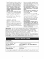 4
4
-
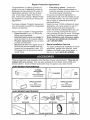 5
5
-
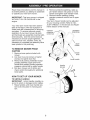 6
6
-
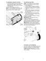 7
7
-
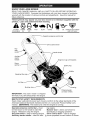 8
8
-
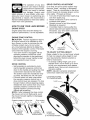 9
9
-
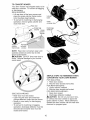 10
10
-
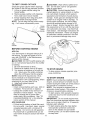 11
11
-
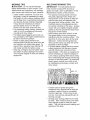 12
12
-
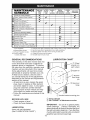 13
13
-
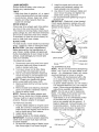 14
14
-
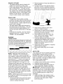 15
15
-
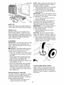 16
16
-
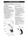 17
17
-
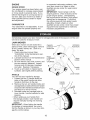 18
18
-
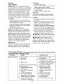 19
19
-
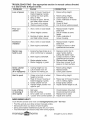 20
20
-
 21
21
-
 22
22
-
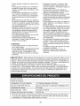 23
23
-
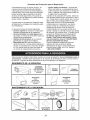 24
24
-
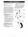 25
25
-
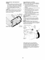 26
26
-
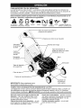 27
27
-
 28
28
-
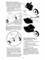 29
29
-
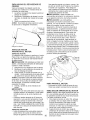 30
30
-
 31
31
-
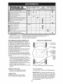 32
32
-
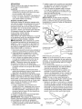 33
33
-
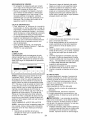 34
34
-
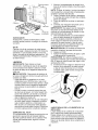 35
35
-
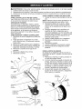 36
36
-
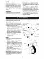 37
37
-
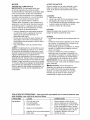 38
38
-
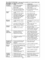 39
39
-
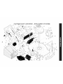 40
40
-
 41
41
-
 42
42
-
 43
43
-
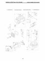 44
44
-
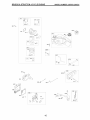 45
45
-
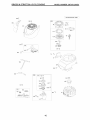 46
46
-
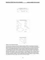 47
47
-
 48
48
-
 49
49
-
 50
50
-
 51
51
-
 52
52


Craftsman 37436 - Rear Propelled Bag Lawn Mower El manual del propietario
- Categoría
- Cortadoras de césped
- Tipo
- El manual del propietario
- Este manual también es adecuado para