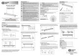
EnviroLite EVRH7ICATA-12 Guía de instalación
- Tipo
- Guía de instalación

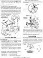
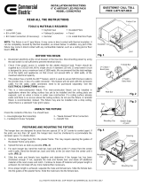
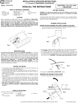
clips of the hanger bars cup underneath the
bottom edges of the joists. Hammer down
the nails of the hanger bars into the
joists to secure the assembly into
place. (FIG. 3 and FIG. 4)
READ ALL THE INSTRUCTIONS
TOOLS & MATERIALS REQUIRED
Before assembling your lighting fixture, refer to the “ELECTRICAL
CONNECTIONS” section. If you feel you do not have electrical wiring
experience, refer to a do-it-yourself wiring handbook or have your fixture
installed by a qualified licensed electrician.
1. To ensure the success of the installation, be sure to read these
instructions and review the diagrams thoroughly before beginning.
2. All electrical connections must be in accordance with local code,
ordinances. If you are unfamiliar with methods of installing electrical
wiring, secure the services of a qualified licensed electrician.
3. Before starting the installation, disconnect electricity at the circuit breaker
or the fuse box. Disconnecting power by using the wall switch is not
sufficient to prevent electrical shock.
4. Check if the power source is suitable for the added electrical load.
Power should be supplied by a 110/120 volt, 60 Hz single circuit. A
standard 120 volt, 15 amp branch circuit is designed to carry a maximum
load of 1800 watts. We recommend that the total wattage of all the lights
and appliances on that circuit, not exceed 80% or 1440 watts, of the
maximum electrical capacity.
5. This product has a SLIDE-N-LOC™ feature, which is used to secure NM
(Romex) cable to the junction box, in lieu of a cable connector. This
feature will not work with BX (armored) cable. For BX cable, cable
connectors need to be purchased separately. See the “ELECTRICAL
CONNECTIONS” section.
6. This is a new-construction fixture. This new-construction fixture can
be installed in applications where the ceiling surface has yet to be
installed and the ceiling joists are exposed, such as when a home is
under new construction. If a ceiling surface already exists and there is
no access above the ceiling surface, do not use this fixture. A remodel
fixture is recommended, instead. This fixture may also be installed onto
a drop ceiling, where there is a standard T-bar grid in place.
7. This fixture is thermally protected. A blinking light may indicate:
CEILING JOIST INSTALLATION
1. Choose the location for the fixture, taking into consideration the required
7” clearance and the accessibility to the electrical supply.
PREPARING AND MOUNTING THE FIXTURE
UNPACK THE FIXTURE
INSTALLATION & OPERATION INSTRUCTIONS –
6” NEW CONSTRUCTION IC RECESSED LIGHTING HOUSING WITH SLIDE-N-LOC™ FEATURE
ALL RIGHTS RESERVED. COPYRIGHT ENVIROLITE 2019
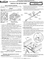
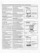
NOTE: This fixture is an
IC type fixture. It may
come in direct contact
with thermal insulation.
It can be completely
covered by thermal
insulation, as shown
below. In addition, any
part of the fixture may
come in direct contact
with any combustible
material, such as a
ceiling joist or floor
board. (FIG. 1)
NOTE: Insulation may
completely cover fixture.
FIG. 1
Joist
Fixture
Insulation
FIG. 2
FIG. 3
Bottom edge
of joist
Nail
Mounting Clip
Joist
FIG. 4
Hammer
Hanger bar
Joist
1
st
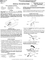
Crease –
Bend Here
1
st
Notch –
Bend Here
2. Raise the housing/hanger bar assembly to the desired location between
the two ceiling joists. Adjust the width of both hanger bars to the
distance between the joists. Position the assembly so that the mounting
Ladder, BX or NM Cable, BX Cable Connectors (if necessary), Keyhole
Saw, Flathead Screwdriver, Hammer, Insulated Pliers, Pencil, UL Listed
Electrical Tape.
be shortened to accommodate the narrower space. To shorten them:
“Male” Bar
“Female” Bar
Mounting
Clip
Mounting
Clip
Housing
Plaster
Frame
Nail
Check the contents of the box. You should have: 1 - Housing/Hanger Bar
Assembly, 1 – Cardboard Circular Template, 3 – “Quick-Connect” Wire
Connectors
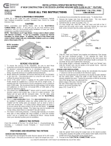
HANGER BAR PREPARATION
The hanger bars are designed for joists that are spaced 16” to 26” (center
to center) apart. If the joists are less than 16” apart, the hanger bars must
3. Slide the plaster frame along the hanger bars to the desired position.
Using pliers squeeze the guides of the plaster frame tightly around the
hanger bars to lock the position of the plaster frame.
4. Proceed to the “ELECTRICAL CONNECTIONS” section.
CAUTION
BEFORE YOU BEGIN
4. Slide the “male” and “female” bars together and determine if the hanger
bar has been shortened enough. If not, separate the “male” and
“female” bars and break off additional material at the next crease and
notch. Continue to break off material until proper length is achieved. Do
not break off any more material than necessary.
5. Once proper length is achieved, separate the “male” and “female” bars.
Slide the “female” bars into the guides of the plaster frame. Slide the
“male” bars into the “female” bars.
1. Remove the hanger bars from the plaster frame. This may require
opening the guides of the plaster frame using pliers.
2. Spread the bars as wide as possible. (FIG. 2)
3. For each hanger bar, bend the “male” bar, back and forth at the 1
st
crease from the center until it splits. Bend the “female” bar, back and
forth, at the 1st notch from the center until it splits. (FIG. 2)
A. An incorrect trim, lamp type or lamp wattage has been installed. Be
sure to use only the trims, lamp types and wattages specified on the
fixture label.
B. The socket plate bracket has been installed above the limiting tab
located inside the can. Be sure that the socket plate bracket is
installed at a level so that the limiting tab is inside the bracket’s
mounting slot.
QUESTIONS? CALL TOLL FREE
1-855-573-6156
MODEL EVRH7ICATA

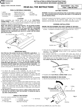
T-bar
ALL RIGHTS RESERVED. COPYRIGHT ENVIROLITE 2019
Hanger
Bar
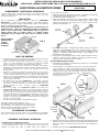
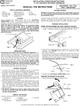
DROP CEILING INSTALLATION
1. Choose the location for the fixture, taking into consideration the required
7” clearance and the accessibility to the electrical supply.
2. Install a ceiling tile onto the T-bar grid at the installation location. Using
the provided template and a keyhole saw make a hole at the desired
location in the ceiling tile.
3. Place the housing/hanger bar assembly onto the ceiling tile into the
newly created hole. Adjust the width of both hanger bars to the distance
between the two T-bars, aligning each mounting clip with the top of its
corresponding T-bar. Press down on all mounting clips until they snap
onto the T-bar. (FIG. 5 and FIG. 6) NOTE: Holes are provided on the
mounting clips that can be used to secure the hanger bars to the T-bar.
Parts (I.e. screws, hex nuts) can be
purchased separately for this purpose.
4. Proceed to the “ELECTRICAL
CONNECTIONS” section.
5. Proceed to the “TRIM
INSTALLATION” section.
5. Install the insulation around the housing, if desired. Install the ceiling
material, such as drywall, over the housing. A template is provided to
assist in making the holes in the ceiling material. (NOTE: Blown-in
Insulation may also be installed after the ceiling material has been
installed.)
6. Proceed to the “TRIM INSTALLATION” section.
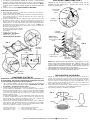
When using the “quick-connect” wire connectors, be sure that there are
no loose/exposed wire strands. Wrap each wire connection using UL
Listed electrical tape.
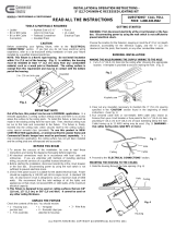
Rectangular
Knockout
NM Cable
(ROMEX)
Junction
box door
Flathead
Screwdriver
FIG. 8
“Quick-Connect”
wire connectors
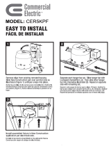
1. Using BX (armored) or NM (Romex) cable, run the supply wiring from the
power supply source to the fixture location. WARNING - Use supply
wires rated 90°C or higher.
2. Open the hinged junction box’s door by lifting the metal latch.
A. FOR BX (ARMORED) CABLE - Break off one of the round knockouts
(FIG. 8) using a screwdriver. Secure an appropriately sized BX cable
connector to the knockout opening. Feed the BX cable through the
connector, providing 6” of slack inside the junction box. Tighten the
connector to secure the cable in place.
B. FOR NM (ROMEX) CABLE – Break off one of the rectangular
knockouts located on the top of the junction box using a screwdriver,
creating a slot. (FIG. 7) Slide the NM cable into the slot, as shown,
making sure there is 6” of slack inside the junction box. (FIG. 8)
3. Remove at least 3” of the cable’s outer sheath and remove the plastic or
paper over-wrap. Strip approximately 3/8” of insulation from the ends of
all supply wires. Using the provided “quick-connect” wire connectors,
make the following wire connections within the junction box:
WHITE Fixture Wire to WHITE (NEUTRAL) Supply Wire
BLACK Fixture Wire to BLACK (HOT) Supply Wire
GREEN Fixture Wire to GREEN / BARE (GROUND) Supply Wire
1. After installing and finishing the ceiling surface, insert the trim into the
housing. Insert the tip of a pencil into the loop of one of the coil springs.
Push the loop upward, stretching the coil spring, inserting the hook into
one of the keyhole slots locate on the socket plate. Repeat with the
remaining coil spring with the remaining keyhole slot to secure the trim in
place. (FIG. 9)
2. Screw a light bulb into the lamp socket and making sure to use the lamp
type an wattage specified on the housing’s lamp replacement label.
3. Installation is complete. Restore electrical power.
FIG. 9
T-bar
Mounting
Clip
FIG. 6
T-bar
Mounting
Clip
FIG. 5
Mounting
Clip
Pry out
knockout
SLIDE-N-LOC™ -
Slide NM cable
into locking slot
4. Close the junction box door until the metal latch snaps, making sure that
all wiring and wire connectors are contained within the box.
FIG. 7
Round
Knockout
Coil Spring
Loop
Hook
Trim
Housing
Keyhole
Slot
NOTE: Additional lighting fixtures may be connected to the fixture’s
junction box. Several knockouts are provided on the junction box to
accommodate additional BX or NM cables intended to connect to other
fixtures. A marking on the junction box door specifies the maximum
number of wires and the maximum wire gauge that can be inserted into
the junction box.
WARNING: First disconnect electricity at the circuit breaker or the fuse
box. Disconnecting power by using the wall switch is not sufficient to
prevent electrical shock.
ELECTRICAL CONNECTIONS
ELECTRICAL CONNECTIONS (CONT.)
TRIM INSTALLATION

LEER TODAS LAS INSTRUCCIONES
HERRAMIENTAS Y MATERIALES NECESARIOS
Antes de ensamblar tu lámpara, consulta la sección de “CONEXIONES
ELÉCTRICAS”. Si crees que no tienes experiencia con cableado eléctrico,
consulta el manual hazlo tu mismo sobre cableado o pídele a un electricista
calificado y certificado que instale tu lámpara.
1. Para garantizar una instalación satisfactoria, asegúrate de leer estas instrucciones
y revisar minuciosamente los diagramas antes de empezar.
2. Todas las conexiones eléctricas deben cumplir con las ordenanzas y códigos
locales. Si no estás familiarizado con los métodos de instalación del cableado
eléctrico, contrata los servicios de un electricista certificado y calificado.
3. Antes de comenzar la instalación, desconecta el suministro de electricidad,
apagando el cortacircuitos o retirando el fusible en la caja de fusibles. Desconectar
la electricidad en el interruptor de la pared no será suficiente para prevenir una
descarga eléctrica.
4. Verifica que la fuente de electricidad sea adecuada para una carga eléctrica
adicional. La electricidad debe venir de un solo circuito de 110/120 voltios, 60 Hz.
Un circuito derivado estándar de 120 voltios y 15 amperios está diseñado para
soportar una carga máxima de 1800 vatios. Recomendamos que el vataje total de
todas las luces y electrodomésticos del circuito no exceda el 80% de la capacidad
eléctrica máxima, o 1440 watts.
5. Este producto tiene una función SLIDE-N-LOC™ para asegurar cables NM
(Romex) a la caja eléctrica y que sustituye el conector de cable. Esta característica
no funciona con cables BX (blindado). Para cables BX, se deben comprar por
separado conectores de cable. Consulta la sección de “CONEXIONES
ELÉCTRICAS”.
6. Esta es una lámpara para construcciones nuevas. Esta lámpara para
construcciones nuevas puede instalarse en construcciones donde la superficie
del techo no ha sido instalada y las vigas del techo están expuestas, como por
ejemplo en hogares aun en construcción. No uses esta lámpara si la superficie del
techo ya está instalada y no hay acceso hacia el otro lado de esta. En ese caso se
recomienda una lámpara para remodelaciones. Esta lámpara también puede
instalarse en techos falsos, donde haya un sistema estándar de suspensión de
barra en T (T-bar grid, en inglés).
7. This fixture is thermally protected. A blinking light may indicate:
INSTALACIÓN EN VIGAS DEL TECHO
1. Elige el lugar para la lámpara, sin olvidar que se necesitan 17,7 cm de holgura
y acceso al suministro eléctrico.
PREPARAR E INSTALAR LA LÁMPARA
DESEMPACAR LA LÁMPARA
¿PREGUNTAS? LLAMA GRATIS AL
1-855-573-6156
INSTRUCCIONES DE INSTALACIÓN Y FUNCIONAMIENTO
CARCASA DE LÁMPARA EMPOTRADA TIPO IC DE 15,24 cm CON FUNCIÓN SLIDE-N-LOC™
TODOS LOS DERECHOS RESERVADOS. COPYRIGHT ENVIROLITE 2019
NOTA: Esta es una lámpara tipo IC. Puede entrar en contacto directo con
aislamiento térmico. Puede ser completamente recubierta con aislamiento
térmico como se muestra abajo. Adicionalmente, todas las partes de la
lámpara pueden entrar en contacto directo con cualquier material
combustible, como por ejemplo una viga de techo o un tablero de piso.
(FIG. 1)
NOTA: El material
aislante puede
recubrir
totalmente
la lámpara.
FIG. 1
Viga
Lámpara
Aislamiento
FIG. 2
FIG. 3
Borde inferior
de la viga
Clavo
Abrazadera
de Montaje
Viga
FIG. 4
Martillo
Barra para
colgar
Viga
1
er
Pliegue–
Doblar Aquí
1
ra
Muesca–
Doblar Aquí
2. Alza ensamblaje de la carcasa/barra para colgar hasta la posición deseada entre
las dos vigas del techo. Ajusta el ancho de las dos barras para colgar según la
distancia entre las vigas. Coloca el ensamblaje de modo que las abrazaderas de
montaje de las barras para colgar queden debajo de los bordes inferiores de las
vigas. Martilla los clavos de las barras para colgar
en las vigas para fijar el ensamblaje
en su sitio. (FIG. 3 y FIG. 4)
Escalera, Cable BX o NM, Conectores de Cable BX (si es necesario), Serrucho de
Punta Fina, Destornillador de Cabeza Plana, Martillo, Alicate Aislado, Lápiz, Cinta
Aislante con clasificación UL.
espacio angosto. Para acortarlas:
Barra "Macho"
Barra "Hembra"
Abrazadera
de Montaje
Abrazadera
de
Montaje
Carcasa
Marco de
Yeso
Clavo
Revisa el contenido de la caja. Debes contar con: 1 - Ensamblaje de la Carcasa/Barra
para Colgar, 1 – Plantilla Circular de Cartón, 3 – Conectores de Cable “Quick-Connect”
PREPARACIÓN DE LA BARRA PARA COLGAR
Las barras para colgar están diseñadas para montarse entre vigas con 40,6 a 66,04
cm de separación (de centro a centro). Si las vigas están a menos de 40,6 cm de
distancia, las barras para colgar se deben acortar para ajustarse al
3. Desliza el marco de yeso a lo largo de las barras para colgar hasta la posición
deseada. Aprieta las guías del marco de yeso fuertemente alrededor de las
barras para colgar con un alicate hasta que el marco de yeso quede fijo en
posición.
4. Continúa con la sección de “CONEXIONES ELÉCTRICAS”.
PRECAUCIÓN
ANTES DE EMPEZAR
4. Desliza las barras "macho" y hembra hasta juntarlas y verifica si la barra de
colgar está lo suficientemente corta. Si no, separa las barras "macho" y
"hembra" y desprende cualquier material de sobra en el pliegue y muesca
siguientes. Desprende material hasta alcanzar el largo apropiado. No
desprendas más de lo necesario.
5. Una vez que se ha alcanzado el largo correcto, separa las barras "macho" y
"hembra". Inserta las barras "hembra" en las guías del marco de yeso.
Inserta las barras "macho" en las barras "hembra".
1. Retira las barras para colgar del marco de yeso. Para lograrlo, es posible que
necesites abrir las guías del marco de yeso con un alicate.
2. Abre las barras lo más posible. (FIG. 2)
3. Dobla hacia adelante y hacia atrás en el 1
er
pliegue desde el centro, la barra
"macho" de cada barra para colgar, hasta que se separe. Dobla la barra
"hembra" hacia adelante y hacia atrás, en la 1
era
muesca desde el centro,
hasta que se separe. (FIG. 2)
MODELO EVRH7ICATA
Esta lámpara está térmicamente protegida. Una luz
parpadeante indicará si una bombilla de tipo o vataje incorrectos
ha sido instalada, o si otra fuente de calor, como por ejemplo un
ducto de calefacción, está interfiriendo con la lámpara. Siempre
revisa el sitio donde planeas instalar la lámpara.

Barra
en T
TODOS LOS DERECHOS RESERVADOS. COPYRIGHT ENVIROLITE 2019
Barra para
Colgar
INSTALACIÓN EN TECHO FALSO
1. Elige el lugar para la lámpara, sin olvidar que se necesitan 17,7 cm de holgura y
acceso al suministro de electricidad.
2. Instala una placa de techo en el sistema de suspensión en T donde irá la lámpara.
Usa la plantilla incluida y un serrucho de punta fina para abrir un orificio sitio
deseado de la placa de techo.
3. Coloca el ensamblaje de la barra de colgar/carcasa en la placa de techo a través
del orificio que abriste. Ajusta el ancho de las dos barras para colgar según la
distancia entre las dos barras en T, alineando cada abrazadera de montaje con el
tope de la barra en T correspondiente. Ejerce presión sobre todas las abrazaderas
de montaje hasta que encajen en la barra en T. (FIG. 5 y FIG. 6) NOTA: Las
abrazaderas de montaje tienen orificios que pueden usarse para asegurar las
barras para colgar a la barra en T.
Las piezas necesarias (es decir, tornillos,
tuercas hexagonales) pueden comprarse
por separado.
4. Continúa con la sección de
“CONEXIONES ELÉCTRICAS”.
5. Continúa con la sección de
“INSTALACIÓN DE LA MOLDURA”.
5. Si lo deseas, instala aislamiento alrededor de la carcasa. Instala el material
del techo, como por ejemplo drywall, sobre la carcasa. Se ha incluido una
plantilla para ayudarte a marcar los orificios en el material del techo. (NOTA:
Se puede instalar Aislamiento Soplado después de instalar el material del
techo).
6. Continúa con la sección de “INSTALACIÓN DE LA MOLDURA” .
Asegúrate de que no haya hilos sueltos o expuestos cuando uses los
conectores de cable “quick-connect”. Envuelve cada conexión con cinta
aislante con clasificación UL.
Entrada
Rectangular
Cable NM
(ROMEX)
Puerta de la
caja eléctrica
Destornillador
de Cabeza
Plana
FIG. 8
Conectores de cable
“Quick-Connect”
1. Usa un cable BX (blindado) o NM (Romex) cable, para llevar la electricidad del
cable de suministro de electricidad hasta la lámpara. ADVERTENCIA- Usa cables
de suministro con clasificación de 90°C o mayor.
2. Levanta el pestillo de metal para abrir la puerta de la caja eléctrica
A. PARA CABLES BX (BLINDADOS) - Con un destornillador, rompe el tapón de
una de las entradas redondas (FIG. 8). Coloca un conector de cable BX apropiado
en la abertura de la entrada. Pasa el cable BX a través del conector, dejando
15,24 cm de cable holgado dentro de la caja eléctrica. Ajusta el conector para
asegurar el cable en su sitio.
B. PARA CABLE NM (ROMEX) – Con un destornillador, rompe el tapón de una de
las entradas rectangulares que están en el lado superior de la caja eléctrica, para
abrir una ranura. (FIG. 7) Inserta el cable NM en la ranura, como se muestra; deja
15,24 cm de cable holgado dentro de la caja eléctrica (FIG. 8)
3. Retira al menos 7,62 cm del revestimiento exterior del cable y quita la envoltura de
papel o plástico. Quita aproximadamente 0,95 cm de aislamiento de los extremos
de los cables de suministro. Usa los conectores de cable “quick-connect” incluidos
para hacer las siguientes conexiones en la caja eléctrica:
Cable BLANCO de la lámpara al Cable de suministro BLANCO (NEUTRAL)
Cable NEGRO de la Lámpara al Cable de suministro NEGRO (VIVO)
Cable VERDE de la Lámpara al Cable de suministro VERDE/ DESNUDO (A TIERRA)
1. Después de instalar y terminar la superficie del techo. Coloca la moldura en la
carcasa. Inserta la punta de un lápiz en el aro de uno de los resortes helicoidales.
Empuja el aro hacia arriba para estirar el resorte e inserta el gancho en una de las
ranuras en forma de cerradura ubicadas en la placa del portabombillas. Haz lo
mismo con el otro resorte helicoidal y la otra ranura en forma de cerradura, para
que la moldura quede fija en su lugar. (FIG. 9)
2. Verifica que tienes una bombilla del tipo y vataje especificados en la etiqueta de la
carcasa de la lámpara; enróscala en el portabombillas de la lámpara.
3. Has terminado la instalación. Restablece la electricidad.
FIG. 9
Barra en T
Abrazadera
de Montaje
FIG. 6
Barra en T
Abrazadera
de Montaje
FIG. 5
Abrazadera
de Montaje
Abrir
entrada
SLIDE-N-LOC™ -
Desliza el cable NM
hasta la ranura de
fijación
4. Cierra la puerta de la caja eléctrica de modo que el pestillo de metal encaje y
todo el cableado y los conectores queden dentro de la caja.
FIG. 7
Entrada
Redonda
Resorte Helicoidal
Aro
Gancho
Moldura
Carcasa
Ranura
en forma de Cerradura
NOTA: Otras lámparas pueden ser conectadas a la caja eléctrica. La caja
eléctrica incluye varias entradas adicionales para cables BX o NM , en caso
de que se quieran conectar otras lámparas. En la puerta de la caja eléctrica
están marcadas las especificaciones sobre el número máximo de cables y el
calibre máximo que se puede conectar a la caja eléctrica.
ADVERTENCIA: Primero desconecta la electricidad en el cortacircuitos o en
la caja de fusibles. Desconectar la electricidad en el interruptor de la pared
no será suficiente para prevenir una descarga eléctrica.
CONEXIONES ELÉCTRICAS
ELECTRICAL CONNECTIONS (CONT.)
INSTALACIÓN DE LA MOLDURA
-
 1
1
-
 2
2
-
 3
3
-
 4
4


EnviroLite EVRH7ICATA-12 Guía de instalación
- Tipo
- Guía de instalación
en otros idiomas
Artículos relacionados
Otros documentos
-
 Commercial Electric CER6CP6743-4PK Guía de instalación
-
 Commercial Electric CER3G10R343BNP Guía de instalación
-
 Commercial Electric CER4G24R463WHP Guía de instalación
-
 Commercial Electric CER5R532WHP Guía de instalación
-
 Commercial Electric CER3LICR3730WH Guía de instalación
-
 Commercial Electric CAT7ICATA-6PK Guía de instalación
-
 Commercial Electric CER5R532WHP Guía de instalación
-
 Commercial Electric CER5KPF Guía de instalación
-
 Commercial Electric 2011001402 Instrucciones de operación
-
 Ledpax Technology LP6ICLED-6 Instrucciones de operación


