Kenmore 76105 El manual del propietario
- Tipo
- El manual del propietario

Owner's Manual
Manual del Propietario
®
THROUGH-THE-WALLAIRCONDITIONER
ACONDICIONADODEAIREA TRAVESDEPARED
Model, Modelo 580.76105
Distributed by Sears, Roebuck and Co., Hoffman Estates, IL 60179
www.sears.com

TABLE OF CONTENTS ........................2
WARRANTY ..............................................2
SAFETY .....................................................3
Important Safety Instructions ...................... 3
ELECTRICAL REQUIREMENTS .......4
INSTALLATION ........................................5
Installation Requirements ......................... 5
Installation ................................................ 6
Procedure A ............................................. 7
Procedure B ............................................. 8
Procedure C........................................... 10
OPERATION ...........................................12
How and Why ......................................... 12
Normal Sounds ...................................... 12
Capacity and Running Time ................... 12
FULL ONE YEAR WARRANTY ON
Features ................................................. 13
Using the Air Conditioner ....................... 13
Control Panel ......................................... 14
Remote Control ...................................... 15
MAINTENANCE .....................................17
Air Filter Cleaning ................................... 17
Air Conditioner Cleaning ........................ 17
How to Remove the Front Grille ............. 17
How to Replace the Front Grille ............. 17
TROUBLESHOOTING .........................18
Before Calling for Service ...................... 18
ESPANOL ................................................2o
MASTER PROTECTION
AGREEMENTS ......................................39
SERVICE NUMBERS ............ Back Cover
THROUGH-THE-WALL AIR CONDITIONER
For one year from the date of purchase, when this
air conditioner is operated and maintained for
normal room cooling according to the instructions in
this owner's manual, Sears will repair this air
conditioner, free of charge, if defective in material or
workmanship.
WARRANTY SERVICE IS AVAILABLE BY
CONTACTING SEARS SERVICE AT
1-800-4-MY-HOME ®.
This warranty applies only while this product is in
use in the United States.
This warranty gives you specific legal rights, and
you may also have other rights which vary from
state to state.
Distributed by Sears, Roebuck and
Co., Hoffman Estates, IL 60179
-2-

IMPORTANT SAFETY INSTRUCTIONS
The safety instructions below will tell you how to use your room air conditioner to avoid harm to yourself or
damage to your ROOM AIR CONDITIONER.
V!_W:!;(_ll_[_FOR YOUR SAFETY
Do not store or use gasoline or other flammable
vapors and liquids in the vicinity of this or any other
appliance. Read product labels for flammability and
other warnings.
PREVENT ACCIDENTS
To reduce the risk of fire, electrical shock, or injury
to persons when using your air conditioner, follow
basic precautions, including the following:
• Be sure the electrical service is adequate for the
model you have chosen.
• If the air conditioner is to be installed in a window,
you will probably want to clean both sides of the
glass first. If the window is a triple-track type with a
screen panel included, you may want to remove
the screen completely before installation.
• Be sure the air conditioner has been securely and
correctly installed according to the instructions in
this manual.
Save this manual and installation instructions for
possible future use in removing or reinstalling this
unit.
• Use gloves when handling the air conditioner.
Be careful to avoid cuts from sharp metal fins on
front and rear coils.
V!_W,.l;i_ll_[dELECTRICAL INFORMATION
The complete electrical rating of your new room air
conditioner is stated on the serial plate. Refer to the
rating when checking the electrical requirements.
• Be sure the air conditioner is properly grounded.
To minimize shock and fire hazards, proper
grounding is important. The power cord is
equipped with a three-prong grounding plug for
protection against shock hazards.
• Your air conditioner must be plugged into a
properly grounded wall receptacle. If the wall
receptacle you intend to use is not adequately
grounded or protected by a time delay fuse or
circuit breaker, have a qualified electrician install
the proper receptacle.
• Do not run air conditioner with packing sheet of
the back of the sleeve, and packing corner and
blue tape of the air conditioner. This could result in
mechanical damage within the air conditioner.
• Do not use an extension cord or an adapter
plug.
_ Avoid fire hazard or electric shock.
Do not use an extension cord or an adapter plug.
Do not remove any prong from the power cord.
Grounding type
wall receptacle
Do not under any
circumstances cut,
remove, or bypass
the grounding prong
from this plug.
ENERGY SAVING IDEAS
• The capacity of the room air conditioner must fit
the room size for efficient and satisfactory
operation.
• install the room air conditioner on the shady side
of your home. A window that faces north is best
because it is shaded most of the day.
• Do not block air conditioner flow inside with blinds,
curtains, or furniture; or outside with shrubs,
enclosures, or other buildings.
• Close the floor and wall registers and the fireplace
damper so cool air does not escape up the
chimney or into the duct work.
• Keep blinds and drapes in other windows closed
during the sunniest part of the day.
• Clean the air filter as recommended in the
MAINTENANCE section of this manual.
• Proper insulation and weather stripping in your
home will help keep warm air out and cool air in.
• External house shading with trees, plants or
awnings will help reduce the air conditioner's work
load.
• Operate heat producing appliances such as
ranges, washers, dryers, and dishwashers during
the coolest part of the day.
-3-

OBSERVEALLLOCALCODESAND
ORDINANCES.
DONOT,UNDERANYCIRCUMSTANCES,
REMOVETHEPOWERSUPPLYCORD
GROUNDPRONG.
ELECTRICALGROUNDISREQUIREDON
THISAPPLIANCE.
208/230-volt60Hzand115-volt60Hz,AC
only,15Afusedandproperlygrounded
electrical supply is required. A time delay fuse
or time delay circuit breaker is recommended.
Use a dedicated circuit, serving only this
appliance.
DO NOT USE AN EXTENSION CORD.
RECOMMENDED GROUNDING METHOD
For your personal safety, this appliance must
be grounded. This appliance has a power
supply cord with a 3-prong grounding plug. To
minimize possible shock hazard, the cord must
be plugged into a mating grounding type wall
receptacle and grounded in accordance with
the National Electrical Code (ANSt/NFPA 70)
latest edition and all local codes and
ordinances. If a mating wall receptacle is not
available, it is the personal responsibility and
obligation of the customer to have a properly
grounded 3-prong wall receptacle installed by a
qualified electrician.
115V~ 230V~
Power cord may include a current interrupter
device. A test and reset button is provided on the
plug case. The device should be tested on a
periodic basis by first pressing the TEST button
and then the RESET button. If the TEST button
does not trip or if the RESET button will not stay
engaged, discontinue use of the air conditioner and
contact a qualified service technician.
NOTE:The shape may be different according to its model.
Use Wall Receptacle Power Supply
_) tandard 125V,
3-wire grounding
receptacle rated
15A, 125V AC
Standard 250V,
3-wire grounding
receptacle rated
15A,250V AC
Standard 250V,
3-wire grounding
receptacle rated
2OA,250V AC
Use t5 AMP. time
delayfuse or 15AMP.
circuit breaker.
Use 20AMP. time
delay fuse or 20AMP.
circuit breaker.
AWARNING
Electrical Shock Hazard
Plug into a grounded 3 prong outlet.
Do not remove ground prong.
Do not use an adapter.
Do not use an extension cord.
Failure to follow these instructions can result in
death, fire, or electrical shock.
3-prong
grounding
plug
Reset-
Test
Ground
prong
supply
cord
(208/230-volt 60 Hz)
--3-prong
grounding
type wall
receptacle
(115-volt 60 Hz)
-4-

Remove packing materials from the wall sleeve and tape
from the air conditioner.
INSTALLATION REQUIREMENTS
If you use an existing wall sleeve, you should
measure its dimensions.
Install the new air conditioner according to these
installation instructions to achieve the best
performance. All wall sleeves used to mount the
new air conditioner must be in good structural
condition and have a rear grille to securely attach
the new air conditioner. (FIG. 1)
With the Kenmore sleeve, you can maintain the
best performance of the new air conditioner.
20-3/32"
(511 ram)
Sram}
Air Conditioner FIG. !
ELECTRICAL SERVICE
Check your available electrical service. The power
supply available must be the same as that shown
on the unit nameplate (found on left side of cabinet).
All models are equipped with a 3-prong service plug
to provide proper service and safe positive
grounding. Do not change plug in any way. Do not
use an adapter plug. If your present wall outlet does
not match your plug, call a qualified electrician to
make the necessary corrections. SAVE CARTON
for storage and this OWNER'S MANUAL for future
reference. The carton is the best way to store unit
during winter or when not in use.
INSTALLATION HARDWARE
ptions
2 Size options
ITEM NAME OF PARTS Q'TY
_1_ i PLASTIC GRILLE 1
i VERTICAL INSULATION STRIP 1
i AROUND INSULATION STRIPS 2
_ i HORIZONTAL INSULATION STRIP 1
i SUPPORT BLOCK 2
;;BAFFLE 1
i TRIM FRAME 2
@ i SHIM 2
_9_ i PLASTIC NUTS AND WASHER SCREWS 4
50 i GRILLE REAR 1
To avoid risk of personal injury, property damage,
or product damage dueto the weight of this
device and sharp edges that maybeexposed:
• Air conditioners covered in this manual pose an
excessiveweight hazard. Two or more people
are neededto move and install the unit.
To prevent injury or strain, use properlifting and
carrying techniques when moving unit.
• Carefully inspectlocation where air conditioner
will be installed. Besure itwill support the weight
ofthe unitover an extended periodof time.
• Handle air conditioner with care. Wear
protective gloveswhenever lifting or carrying the
unit. AVOID the sharp metalfins offront and
rear coils.
• Make sure air conditioner does not fall during
installation.
-5-
REQUIRED TOOLS:
• Tight Fitting gloves
• Standard screwdriver
• Phillips screwdriver
• Pliers
• Sharp knife
• 3/8-inch open end
wrench or adjustable
wrench
• 1/4-inch hex socket
and ratchet
• Tape measure
• Electric drill
• 1/4-inch drill bit

INSTALLATION
We strongly recommend the removal of the
oldwall sleeve and the installationof a new
Kenmore Wall Sleeve,
If you decide to keep the existing wall sleeve,
you haveto redirect the louvers at the back of the
wall sleeve illustration. The use of pliers is
recommended. If you DO NOT redirect,you run
the risk of poor performance or product failure.
This is not covered under the terms of the
Kenmorewarranty.
• Pick a location which will allow the conditioned air
to blow into the area you want. Good installation
with special attention to the proper position of the
unit will lessen the chance that service will be
needed.
ITEMS IN INSTALLATION HARDWARE
You may not need all parts in the kit. Discard
unused parts
ITEM (inches)
Plastic grille
Vertical insulation strip
Around insulation Strips
Horizontal Insulation Strip
Support Block
Baffle
Shim
Trim Frame
Washer Screw
Nuts(Plastic)
Grille Rear
263/4 X 161/2
159/18 X 13/8X 13/8
671/8 X 13/8 X 25/32
5927/32 X 13/8 X 13/_
237/32 X 13/8 X 13/I(
13/4 X 13/8 X 45/18
14 x 41/2 x 1/8
1113/18X 1 X3/4
Qty.
1
1
1
1
1
2
1
2
2
4
4
1
HOW TO INSTALL
H Identify the existing wall sleeve before installing
the unit from the listed below.
Brand Wall Sleeve Dimensions (inches)
White-Westinghouse
Frigidaire
Carrier (52F series)
General Electric
/Hotpoint
Width
25-1/2
26
Whirlpool 25-7/8
Fedders/Emerson 27
Sears/Kenmore 25-7/8
Emerson/Fedders 26-3/4
Carrier (51S Series) 25-3/4
Friedrich 27
Height Depth
15-1/4 16, 17-1/2
or 22
15-5/8 16-7/8
17-1/8
16-1/2
or 23
16-3/4 16-3/4
or 19-3/4
15-17/32 16-23/32
15-3/4 15
16-7/8 18-5/8
16-3/4 16-3/4
NOTE: All wall sleeves used to mount the new Air
Conditioner must be in sound structural condition
and have a rear grille that securely attaches to
sleeve, or rear flange that serves as a stop for the
Air Conditioner.
_-'_ Remove old air conditioner from existing wall
sleeve.
_1 Clean the interior of an existing sleeve.
(Do not disturb seals.)
D Wall sleeve must be securely fastened in wall
before installing the air conditioner. Use the
nails or screws through sleeve into wall, if
needed. Repaint sleeve if needed.
_4J Prepare the wall sleeve for installation of the
unit. If you plan to use your existing wall sleeve,
and it is not Kenmore, use procedure B or C
below.
Procedure Brand Depth(inches)
A Sears/Kenmore 16-23/32
White-Westinghouse
Frigidaire Carrier 16, 17-1/2
or 22
(52F series)
B General Electric
16-7/8
/Hotpoint
Whirlpool 17-1/8 or 23
Carrier (51S series) 18-5/8
16-3/4
Fedders/Emerson
or 19-3/4
C
Emerson/Fedders 15
Friedrich 16-3/4
Q Install new unit into wall sleeve.
CAUTION: When installation is completed,
replacement unit MUST have a rearward slope as
shown. To achieve 1/4" slope, remove the backing
from the 11-13/16" shim strips and attach them as
shown below in Fig. 2. Place the higher portion of
shim to the front of the rib on base of wall sleeve.
1" highI [
SHIM PLACEMENT
_I3/4 " High
UNiT Wall S_eeve
FRONTI ...........L!
UNIT INSTALLATION
FIG. 2
-6-

PROCEDURE A
n
If you are using the new sleeve (optionally
supplied with your unit),skip to step 3.
Otherwise, install the plastic grille from the kit.
Cut the plastic grille to 25-1/2" wide and
15-114" high. Place the plastic grille to the
inside of the wall sleeve at the rear flange.
FIG. 3
_'_ Fasten the 4 washer screws to secure the grille
to the wall sleeve. If you need plastic nuts to
mount plastic grille to the inside of the wall
sleeve, there are plastic nuts in the installation
kit. The nuts are installed from the inside of the
sleeve and are pressing into the square holes
of the rear flanges.
FIG. 4
_J Remove the backing from the Vertical
Insulation strip 158/18 x 13/8X 13/8and attach that
to the inside right of the sleeve as shown
below. Remove the backing from the Around
Insulation strip 671/8 x 13/8X 25/32 and attach that
to the inside front of the sleeve as shown
below.
Indoor Outdoor
9 1/2" = 6" "
FIG. 5
D Remove the metal rear grille and replace it with
the plastic rear grille.
-7
Remove the PIastic rear gritle
metal rear c
FIG. 6
_[_J Install the new unit into the wall sleeve.
_JTo assemble trim, snap the tab of each piece
into the slot of the other piece as shown below.
Slide trim over the front of the air conditioner
until trim is flush with sleeve as shown below.
Trim (2 ea)
Wall
FIG. 7
. Airconditionerscoveredinthismanualposean
excessiveweighthazard.Twoor morepeopleare
neededtomoveandinstalltheunit.
Topreventinjuryor strain,useproperliftingand
carryingtechniqueswhenmovingunit.
. Whenhandlingtheair conditioner,becarefultoavoid
cutsfromsharpmetalfinsonfrontandrearcoils.
•Makesureairconditionerdoesnotfallduring
removal.
. If unitdoesnotoperateafterinstallationcheck,to be
surethecircuitinterrupterhasnotbeentripped.Refer
totheTroubleshootingguideforresetprocedure.

PROCEDURE B
H Redirect the louvers at the back of the wall
sleeve to 60 ° angle as shown in the FIG 8. The
use of pliers is recommended.
Rear Louvers
(Top View)
7 3132"
FIG. 8
I_lf the wall sleeve already has a rear grille, skip
to step 4. If the wall sleeve does not have a rear
grille or Iouvered panel, install the plastic grille
from the kit. Cut the plastic grille to 25-1/2" wide
and 15-1/4" high. Place the plastic grille to the
inside of the wall sleeve at the rear flange.
Place the plastic grille
FIG. 9
I[_ Fasten the 4 washer screws to secure the grille
to the wall sleeve. If you need plastic nuts to
mount plastic grille to the inside of the wall
sleeve, there are plastic nuts in the installation
kit. The nuts are installed from the inside of the
sleeve and are pressed into the square holes of
the rear flanges.
or
Fasten the screws
FIG. 10
I_ Remove the backing from the Vertical Insulation
strip 159/18 x 13/8 x 13/8and attach that to the
inside right of the sleeve as shown below.
Remove the backing from the Around Insulation
strip 671/8 x 13/8X 25/32 and attach that to the
inside front of the sleeve as shown below.
Indoor Outdoor
9 1/2" _ _ 6" '
FIG. 1
I_ Remove the metal rear grille and replace it with
the plastic rear grille.
Removethe PIastic reargrille
metal rear gr
FIG. 12
r_lf the depth of your existing wall sleeve is less
than or equal to 18", skip to step 7. Otherwise,
cut the baffles and the support blocks according
to length "A" in the table below.
Depth"D"oftheexisting
wallsleeve(inches)
18 <D _<18-5/8
18-5/8 <D <19-3/4
19-3/4<D _<22
Length"A"
(inches)
3/4
1-3/4
4
_ upport
Block
• ._ Baffle
A_ FIG. 13
-8-

PROCEDURE B
WRemove the backing from the support blocks
and attach them to the inside of the wall sleeve
as shown FIG 14. Slide the baffle into slots of
the support blocks.
Wall
Wall
Sleeve
(7 3/32")
Biock
FIG. 14
f_ Install the new unit into the wall sleeve.
Q Assemble trim as described in Step 6,
Procedure A.
• Airconditionerscoveredinthis manualposean
excessiveweighthazard.Twoor morepeopleare
neededtomoveandinstalltheunit.
Topreventinjuryor strain,useproperliftingand
carryingtechniqueswhenmovingunit.
. Whenhandlingtheairconditioner,becarefultoavoid
cutsfromsharpmetalfinsonfrontandrearcoils,
. Makesureairconditionerdoesnotfallduring
removal.
. If unitdoesnotoperateafterinstallationcheck,to be
surethecircuitinterrupterhasnotbeentripped.Refer
totheTroubleshootingguideforresetprocedure,
-9-

PROCEDURE C
H Redirect the louvers at the back of the wall
sleeve to 60 ° angle as shown in the FIG 15.
The use of pliers is recommended.
73/32"
002 &to°
Rear Louvers
(Top View)
FIG. 15
I_lf the wall sleeve already has a rear grille, skip
to step 4. If the wall sleeve does not have a rear
grille or Iouvered panel, install the plastic grille
from the kit. Cut the plastic grille to 26-1/2" wide
and 15-1t2" high. Place the plastic grille to the
inside of the wall sleeve at the rear flange.
Place the plastic grille
FIG. 16
I[_ Fasten the 4 washer screws to secure the grille
to the wall sleeve. If you need plastic nuts to
mount plastic grille to the inside of the wall
sleeve, there are plastic nuts in the installation
kit. The nuts are installed from the inside of the
sleeve and are pressed into the square holes of
the rear flanges.
or
Fasten the screws FIG. 17
_J Remove the backing from the Horizontal
insulation strip 237/82 x 13/8 x 13/18and attach
that to the inside right of the sleeve as shown
below. Remove the backing from the Around
insulation strip 5927/32 x 13/8x 13/8and attach
that to the inside front of the sleeve as shown
below.
Indoor Outdoor
8 1/2"
FIG. 18
El
If the depth of your existing sleeve is less than
or equal to 18", skip to step 7. Otherwise, cut
the baffles and the support blocks according to
Length "A" in the table below.
Depth"D"oftheexisting
wailsleeve(inches)
18 <D_<18-%
18-5/8<D <19-3/4
19-3/4<D _<22
Length"A"
(inches)
3/4
1-8/4
4
_ upport
Block
"_I_F Baffle
IG. 19
ir_ Remove the backing from the support blocks
and attach them to the inside of the wall sleeve
as shown FIG 20. Slide the baffle into slots of
the support blocks
Wall
Wall
Sleeve
7 3'32")
Block
FIG. 20
-10-

PROCEDURE C
lil
To achieve rearward slope for unit draining,
remove the backing from the 1113/16" shim
strips and attach them as shown below in Fig.
21. The higher portion of shim is to be placed
in front of the rib on the base of wall sleeve.
h,0h_ r-
High
FIG. 21
16,,i 16, 1
FIG. 22
D Remove the metal rear grille and replace it with
the plastic rear grille.
Removethe Plastic rear grille
metal rear (
. FIG. 23
°Airconditionerscoveredin thismanualposean
excessiveweighthazard.Twoor morepeopleare
neededto moveandinstalltheunit.
Topreventinjuryorstrain,useproperliftingand
carryingtechniqueswhenmovingunit.
°Whenhandlingtheairconditioner,becarefultoavoid
cutsfromsharpmetalfinsonfrontandrearcoils.
°Makesureairconditionerdoesnotfallduring
removal.
• Ifunitdoesnotoperateafterinstallationcheck,tobe
surethecircuitinterrupterhasnotbeentripped.Refer
totheTroubleshootingguideforresetprocedure.
_'_ Install the unit into the wall sleeve
new
_1_ Assemble trim as described in Step 6,
Procedure A.
-11-

HOW AND WHY
Your room air conditioner provides the following
functions to make hot weather living more
comfortable:
• Cools and circulates room air.
• Lowers humidity by removing excess moisture.
• Filters out summertime dust, dirt, and some
airborne impurities.
The air conditioner performs these functions by
drawing room air through a filter which traps dust
and dirt particles. The air then passes over a
cooling coil which refrigerates the air and removes
excess moisture. The same air is then returned to
the room- cooler, drier, and cleaner. Moisture
removed from the room air is carried to the outside
and evaporated.
Your air conditioner is designed to be easy to
operate and to provide plenty of cooling power.
NORMAL SOUNDS FIG.24
Aside from the regular fan motor and compressor
sounds coming from your air conditioner, you will
once in a while hear a pinging sound. This is the
result of moisture being picked up from the air in the
room and thrown against the air conditioner's fan.
This is normal and should not be cause for concern.
Also, do not be alarmed if you hear a slight hissing or
gurgling sound coming from your air conditioner after
it is off. These are normal coolant noises.
CAPACITY AND RUNNING TIME
Proper unit size is important in deciding the desired
comfort for the area you want to cool. The proper
size is determined by the number of square feet in
the area to be cooled.
Whenever the heat or humidity load is above normal
the air conditioner must run longer and more often
to keep the desired temperature you have selected.
Under heavy heat load conditions the air conditioner
may need to run constantly to keep the temperature
you want.
At times using the MED FAN setting to circulate the
room air may make it comfortable even though you
do not have the air conditioner set to cool the air.
This will decrease your cost of use.
Unit Vibration
The unit may vibrate
and make noise
because of poor wall
or window
construction.
Fan
You may hear air
movement from the
fan.
Compressor
The modern high
efficiency compressor
may have a high pitched
hum or pulsating noise
that cycles on and off.
Condenser
You may hear
droplets of water
hitting the condenser,
causing a pinging or
clicking sound.
FIG. 24
-12-

FEATURES
THE UNIT
6 3 7 2 8 4 5 1 FIG.25
1. CABINET
2. HORIZONTAL AIR DEFLECTOR
(Vertical Louver)
3. VERTICAL AIR DEFLECTOR
(Horizontal Louver)
4. AIR DISCHARGE
5. FRONT GRILLE
6. INLET GRILLE (Air intake)
7. AIR FILTER
8. VENT CONTROL
USING THE AIR CONDITIONER
_To reduce the risk of fire, electric
shock, or injury to persons, read the important
SAFETY instructions section before operating this
appliance.
To begin operating the air conditioner after
installation, follow these steps:
1. Plug in the air conditioner. (To prevent electrical
hazards, do not use an extension cord or an
adapter plug.)
2. Set the TEMP control to the coolest setting.
3. Set the MODE control at the highest COOL level.
4. Adjust the louvers for comfortable air flow.
5. Once the room has cooled, adjust the TEMP and
MODE control to the setting you find most
comfortable.
NOTE : If the air conditioner is turned off, wait 3
minutes before restarting. This allows pressure
inside the compressor to equalize. Failure to wait 3
minutes before restarting may cause inefficient
operation.
If you move the TEMP control to a warmer, then
immediately back to a cooler setting, the unit will
shut off. Wait 3 minutes before restarting.
Refer to the AIR CONDITIONER FEATURES
section for other settings.
VENT CONTROL
The Vent Control allows the air conditioner to either
recirculate inside air (CLOSE) or exhaust air to the
outside (OPEN). (FIG. 26)
• The CLOSE position is used when maximum
cooling is desired. It may also be used for air
recirculation without cooling when the air
conditioner is set in the FAN position.
• The OPEN position removes stale air from the
room and exhausts it to the outside. Fresh air is
drawn into the room through your home's normal
air passages.
• The OPEN or CLOSE position can be used with
any fan selection.
PULL OPEN / PUSH CLOSE
FIG. 26
-13-

CONTROL PANEL
_FAN SPEED
• Every time you push this button, it advances the setting as follows: {High -_ Low-* Med-_ High}
(_TIMER
- SHUT-OFF TIME
• You will usually use shut-off time while you sleep.
• If unit is running, use Timer to set number of
hours until shut-off.
• For your sleeping comfort, once Time is set, the
Temperature setting will raise 2°F after 30 min.,
and once again after another 30 min.
• Push Timer button to advance setting from 1Hour
-* 2Hours -* ...-_ 12Hours maximum.
- START TIME
• If unit is off, use Timer to set number of hours
before unit starts.
• Push Timer button to advance setting from 1Hour
-, 2Hours -, ... -, 12Hours maximum.
REMOTE CONTROL SIGNAL
RECEIVER
TEMPERATURE SETTING
• Usethis buttonto automaticallycontrolthe
temperatureofthe room.
Thetemperaturecanbe setwithina range
of60°Fto 86°Fbyincrementsof 1°F.
• Thesettingappearsin thedisplay.
POWER
• To turn the air conditioner ON, push this
button.
To turn the air conditioner OFF, push the
button again.
• This button takes priority over any other
button.
• When you first turn it on, the unit is in
cool mode, High fan speed, Temperature
setting at 72°F.
MODE
- Push this button to shift mode of operation from COOL -_ ENERGY SAVER -_ FAN.
- COOL:
• Fan runs continually for normal cooling operation
- ENERGY SAVER:
• The fan stops when the compressor stops cooling. Approximately every 3 minutes the fan will turn on
and the unit will check the room air temperature to determine if cooling is needed.
- FAN:
• Fan-only operation.
When power is restored after an electrical power failure, the unit will begin to run at its last setting.
-14-

REMOTE CONTROL
NOTE: The Remote Control will not operate properly if strong light shines on the sensor window of the Air
Conditioner or if there are obstacles between the Remote Control and the Air Conditioner.
Every time you push button, you will hear a beep from the Air Conditioner.
POWER
• To turn the air conditioner ON, push this button.
To turn the air conditioner OFF, push the button again.
• This button takes priority over any other button.
• When you first turn it on, the unit is in cool mode, High fan speed,
Temperature setting at 72°F.
• Auto Restart
In the event at a power failure, the unit will run at the previous setting once
power returns.
TEMPERATURE SETTING
•Usethis buttontoautomaticallycontrolthetemperatureoftheroom.
Thetemperaturecanbe setwithina rangeof 60°Fto 86°Fby
incrementsof I°F.
•Thesettingappearsin thedisplay.
FAN SPEED
•Everytimeyou pushthis buttonit advancesthe settingasfollows:
(High =+ Low =+ Meal =+ High)
TIMER
- SHUT-OFF TIME
• You will usuallyuse shut-off time while you sleep.
• If unit is running,use Timer to set number of hours until shut-off.
• For your sleepingcomfort,once Time is set,theTemperaturesettingwill
raise 2°F after 30 min,and once againafter another 30 min.
• Push Timer button to advance settingfrom 1Hour-+ 2Hours-+...-+
12Hours maximum,
- STARTTIME
•If unitis off,useTimerto setof hoursbeforeunitstarts.
•PushTimer buttonto advancesettingfrom1Hour-, 2Hours-* ...-*
12Hoursmaximum.
• Temp •
Powe r
Fan Speed
S I /' Timer Mode
MODE
- Push this button to shift mode of operation from COOL -* ENERGY SAVER -_ FAN.
- COOL:
• Fan runs continually for normal cooling operation
- ENERGY SAVER:
• The fan stops when the compressor stops cooling. Approximately every 3 minutes the fan will turn on
and the unit will check the room air temperature to determine if cooling is needed.
- FAN:
• Fan-only operation.
/
-15-

INSERTING THE REMOTE CONTROL
BATTERIES
1. Remove the cover from the back of the remote
controller.
2. Insert two batteries.
• Be sure that the (+) and (-) directions are
correct.
• Be sure that both batteries are new.
3. Reattach cover.
FIG. 27
• Do not use rechargeable batteries.
Make sure that both batteries are new.
• In order to prevent discharge, remove the batteries
from the remote control if the air conditioner is not
going to be used for an extended period of time
Keep the remote control away from extremely hot
or humid places.
To maintain optimal operation of the remote
control, the remote sensor should not be exposed
to direct sunlight.
• The remote control can be mounted on a wall
using the mountable holder.
FIG. 28
HORIZONTAL AIR-DIRECTION
ADJUSTMENT
• The horizontal air direction is adjusted by moving
vertical louver.
• The vertical louver control levers are located in the
right and left side of the air discharge.
FIG. 29
VERTICAL AIR-DIRECTION ADJUSTMENT
• The vertical air direction is adjusted by moving the
horizontal louvers.
FIG. 30
-16-

AIR FILTER CLEANING
The Air Filter will become dirty as it removes dust
from the inside air. It should be washed at least
every 2 weeks. If the Air Filter remains full of dust,
the air flow will decrease and the cooling capacity
will be reduced, possibly damaging the unit.
• Pull the inlet grille forward and pull out the air filter.
(FIG. 31)
• Wash the Air Filter under the faucet with warm
water. Be sure to shake off all the water before
replacing the filter. (FIG. 32)
FIG. 31 FIG. 32
AIR CONDITIONER CLEANING
Clean the front grille and inlet grille by wiping with a
cloth dampened in a mild detergent solution.
The cabinet may be washed with mild soap or
detergent and lukewarm water, then polished with
liquid appliance wax.
To ensure continued peak efficiency, the condenser
coils (outdoor side of the unit) should be checked
periodically and cleaned if they become clogged
with soot or dirt from the atmosphere. Brush or
vacuum exterior coils to remove debris from fins.
FIG. 33
HOW TO REMOVE THE FRONT
GRILLE
• Open the inlet grille.
• Remove the screw securing the Front Grille.
• Push the grille up from the bottom and pull the top
of the grille away from the case to lift the top tabs
out of their slots.
FIG. 34
HOW TO REPLACE THE
FRONT GRILLE
Attach the front grille to the cabinet by inserting the
tabs on the grille into the slots on the front of the
cabinet. Push the grille in until it snaps into place.
FIG. 35
-17-

BEFORE CALLING FOR SERVICE
Check the following list to be sure a service call is really necessary. A quick reference to this manual may
help you avoid an unneeded service call.
THE AIR CONDITIONER WILL NOT OPERATE
Check if...
TheCurrentinterrupterDeviceistripped.
Wail plug disconnected.
House fuse blown or circuit breaker tripped.
Power is OFF.
Unit was turned off and then on tooquickly.
TEMP Control setwarmer than room temperature.
Then...
Press the RESET button located on the power cord plug.
if the RESET button will not stay engaged, discontinue use of the
air conditioner and contact a qualified service technician.
Push plug firmly into wail outlet.
Replace fuse with time delay type or reset circuit breaker.
Push the power button.
Set unit offand wait 3 minutes before restarting.
Set TEMP Control to a lower number.
AIR FROM UNIT DOES NOT FEEL COLD ENOUGH.
Check if... Then...
FAN SPEED set at LOW. Push FAN SPEED button to set at HI.
TEMP Control set toowarm. Set TEMP Control to a lower temperature.
Room temperature below 70°F (21°C). Cooling may not occur until room temperature rises above 70°F (21°C).
Temperature sensing tube touching evaporator coil, Straighten tube away from evaporator coil.
located behind front grille.
THEAIR CONDITIONERCOOLING, BUTROOM IB TOO WARM - ICEFORMING ON COOLING COIL BEHINDINLETGRILLE.
Check if... Then...
Outdoor temperature below 70°F (21°C). To defrost the coil, set the MODE to FAN, FAN speed to High.
Air filter may be dirty. Clean air filter. Refer to Maintenance section of owner's manual.
To defrostthecoil,set the MODE to Cool, Fan speed to high, and the
TEMP Control set too tow. Temp control to a higher temperature.
THEAIR CONDITIONERCOOLING,BUT ROOMISTOOWARM
Check if... Then...
Dirty air fitter- air restricted. Clean air filter. Refer to Maintenance section of owner's manual.
TEMP Control set toowarm. Set TEMP Control to a lower temperature.
Front of unit is blocked by drapes, blinds, furniture, etc. Clear blockage in front of unit.
Air distribution is restricted.
Doors, windows, registers, etc. open. Cold air escapes. Close doors, windows, registers, etc.
Unit recently turned on in hot room. Allowadditionaltimetoremovestoredheatfromwalls,ceiling,ficor,andfurniture.
THE AIR CONDITIONER TURNS ON AND OFF RAPIDLY.
Check if... Then...
Outside temperature isextremely hot. Set FAN SPEED on HI to minimize the cooling toad.
Unit isset to energy saver mode. Approximately every 3 minutes thefan wil! turn on andthe unit will check
the room air temperature to determine if cooling is needed. This is
normal energy saver mode operation.
NOISE WHEN UNIT IS COOLING.
Check if... Then...
Soundoffan hittingwater- fromthemoistureremovatsystem. This is normal when humidity ishigh. Closedoors, windows, and registers.
Window vibration - poor installation. Refer to installation instructions or check with installer.
WATER DRIPPING INSIDE ROOM WHEN UNIT IS COOLING.
Check if... Then...
The air conditioner is improperly installed, installationTiltair conditionerinstructionsslightlyor tocheckthe outsidewith installer,to allow water drainage. Refer to
WATER DRIPPING OUTSIDE WHEN UNIT IS COOLING.
Check if... Then...
The unit is removing largequantities of moisture This isnormal during excessively humid days.
from humid room.
-18-

-19-

CONTENIDO ...........................................20
GARANTiA ..............................................2o
SEGURIDAD ..........................................21
Instrucciones importantes de seguridad ---21
REQUlSlTOS ELECTRICOS .............22
INSTALAClON ........................................23
Requisitos de instalacion ....................... 23
Instalacion .............................................. 24
Procedimiento A ..................................... 25
Procedimiento B..................................... 26
Procedimiento C..................................... 28
FUNClONAMIENTO ............................3o
CSmo y por que ...................................... 30
Ruidos normales .................................... 30
Capacidad y tiempo de ejecucion .......... 30
Caracteristicas ....................................... 31
Uso del aire acondicionado .................... 31
Panel de control ..................................... 32
Mando a distancia .................................. 33
MANTENIMIENTO ................................35
Limpieza del filtro de aire ....................... 35
Limpieza del aire acondicionado ............ 35
CSmo desmontar la rejilla frontal ........... 35
CSmo sustituir la rejilla frontal ................ 35
SOLUClON DE AVERiAS ..................36
Antes de solicitar el servicio
de reparacion ......................................... 36
ACUERDOS PRINClPALES DE
PROTECCION ........................................39
NUMEROS DE SERVIClO .........Cubiertatrasera
GARANTiACOMPLETADE UNANO DEL
APARATODE AIREACONDICIONADODE
PARED
Durante unaria, a contar a partir de la fecha de compra, cuando
este aparato de aire acondicionado funcione para el enfriamiento
normal de una habitacion y reciba mantenimiento, todo ella
segOnlas instrucciones de este Manual dei propietario, Sears
reparara este aparato de aire acondicionado, de forma gratuita, si
tuviera algOndefecto de fabricacion o materiales.
EL8ERVIClO DEGARANTiAPUEDE
CONTACTARSEEN EL8ERVICIO DEATENCION
AL CLIENTEDESEARSEN EL1-800-4-MY-HOME®.
Esta garantia se aplica soto durante el uso deeste producto en
los Estados Unidos.
Esta garantia te concede derechos legales especificos y puede
que usted tenga otros dereohos adicionates que varian segQnel
estado.
Distributed by Sears, Roebuck and
Co., Hoffman Estates, IL 60179
- 20 -

INSTRUCCIONES IMPORTANTES DE SEGURIDAD
Las instrucciones de seguridad a continuaci6n le informaran c6mo utilizar su aire acondicionado para evitar
lesiones a usted mismo o daSos a su AIRE ACONDICIONADO.
[t'!_'.lJ_;tl;lI[_r;1PARA SU SEGURIDAD
No almacene ni utilice gasolina u otros vapores y liquidos
inflamables en Ias cercanias de este o cualquier otro
electrodomestico. Lea las etiquetas del producto para
conocer las advertencias de inflamabilidad y otras.
_ PREVENIR ACClDENTES
Para reducir el riesgo de fuego, descargas electricas, o
lesiones a personas al utilizar su aire acondicionado,
respete las precauciones basicas, incluyendo las
siguientes:
• Asegurese de que el servicio electrico es adecuado
para el modelo que usted ha elegido.
• Siva a instalar el aire acondicionado en una ventana,
usted probablemente deseara limpiar ambos lados del
cristal primero. Si la ventana es del tipo de tres guias
con panel de pantalla incluido, usted puede desear
quitar totalmente la pantalla antes de ia instalaci6n.
• Asegurese de que el aire acondicionado se ha estado
instalado segura y correctamente segun las
instrucciones de este manual. Guarde este manual e
instrucciones de instalacion para futuras consultas de
desmontaje o reinstalaci6n de esta unidad.
• Utilice guantes para manipular el aire acondicionado.
Tenga cuidado de evitar cortes de los bordes afilados
de metal en Ias bobinas frontal y trasera.
INFORMACION ELECTRICA
El regimen electrico compteto de su nuevo aire
acondicionado esta indicado en la placa serie. Consulte
el regimen al comprobar los requisitos electricos.
• AsegOrese de que el aire acondicionado esta
correctamente puesto a tierra. Para reducir al minimo ei
riesgo de descargas e incendios, la puesta a tierra
correcta es muy importante. El cable de alimentacion esta
equipado con un enchufe de puesta a tierra de tres
dientes para su proteccion contra descargas electricas.
• Su aire acondicionado debe estar enchufado a un
enchufe de pared correctamente puesto a tierra. Si el
enchufe de pared que planea utilizar no esta
adecuadamente puesto a tierra o protegido por un fusible
de retardo o un interruptor, Ilame a un electricista
cualificado para instalar el enchufe apropiado.
• No ponga en funcionamiento el aire acondicionado con
la hoja de embalaje adherida a la parte posterior del
soporte de pared, y ia esquina de embalaje y cinta azul
del aire acondicionado. Esto podia causar daBos
mecanicos dentro del aire acondicionado.
• No utilice un cable alargador o un enchufe
adaptable.
_ Eviteel riesgo de incendios o descargas
electricas. No utitice un cable aIargador o un enchufe
adaptable. No quite ningOndiente del cable de alimentacion.
Enchufe de
pared del tipo _[Bajo
puesta I
ninguna
a tierra _ Jcircunstancia corte,
i Idesm°nte ° puentee el
Idiente de puesta a tierra
de este enchufe.
Reponga
Cable de alimentacion _ //Sj_ _Prueba
con enchufe de puesta a
tierra de tres dientes
IDEAS PARA EL AHORRO DE ENERGiA
• La capacidad del aire acendicionade debe Ilenar el
tamaBo de la habitacion para Iograr un funcionamiento
eficiente y satisfactorio.
• Instale el aire acondicionado en un lugar sombreado de
su hogar. Lo mejor es una ventana al norte porque
estara sombreada la mayor parte del dia.
• No bloquee el flujo de aire interior con persianas,
cortinas o muebles; o el exterior con arbustos,
cerramientos u otras edificaciones.
• Cierre los registros de suelo y pared y ei regulador de
tiro de la chimenea para que el aire frio no se escape
por la chimenea y hacia los conductos.
• Mantenga cerradas las persianas y cortinas en otras
ventanas durante las horas mas soleadas del dia.
• Limpie el filtro de aire segOn Io recomendado en ia
seccion MANTENIMIENTO de este manual.
• El aislamiento apropiado y ei encintado en las ventanas
de su hogar mantendra ei aire caliente fuera y el aire
frio dentro.
• Las cubiertas externas de la casa que den sombra junto
con arboles, plantas o toldos ayudaran a reducir Ia
carga de trabajo del aire acondicionado.
• Utilice los electrodomesticos que produzcan calor como
estufas, lavadoras, secadoras y Iavaplatos durante las
horas mas frias del dia.
-21 -

RESPETE TODOS LOS CODIGOSY
REGLAMENTOS.
BAJO NINGUNA CIRCUNSTANCIA CORTE,
QUITE O EVITE EL USO DE LA CONEXION A
TIERRA DE ESTA CLAVIJA.
LA TOMA A TIERRA ES NECESARIA EN ESTE
ELECTRODOMI_STICO.
Es necesaria una fuentede alimentaci6n electrica
de 208/230 voltios, 60 Hz y 115-voltios,60 Hz, s61o
AC, con fusible de 15 Ay correctamente puesta a
tierra. Se recomienda el uso de un fusible o
interruptor de retardo. Utilice un circuito dedicado,
Qnicamentepara este electrodomestico.
NO USE CABLE ELECTRICO DE EXTENSION.
MI_TODORECOMENDADO DE CONEXION A
TIERRA
Por su propia seguridad este aparato debe
conectarse a tierra. Este aparato viene equipado
con un cable de alimentaci6n y una clavijade tres
terminales. Para reducir al maximo el peligro de
choque electrico, el cable debe estarconectado a
una conexi6n de pared con conexi6n a tierra, y esta
conexi6n debe hacerse de acuerdo con la Qltima
edici6n del C6digo Electrico Nacional (ANSI/NFPA
70), asi como con los c6digos y reglamentos
locales. Si no existe una conexi6n de pared
adecuada, el clientetiene la responsabilidad y la
obligaci6n de mandar instalar, con un electricista
calificado, una conexi6n de pared adecuada de tres
terminales con conexi6n a tierra.
115V~
m _ _ i
230V~
Elcabledealimentaci6npuedeincluirundispositivo
interruptordecorriente.Lacarcasadetenchufecuenta
conunbot6ndepruebayotrodereinicio.Eidispositivo
debecomprobarseperi6dicamentepresionando
primeroelbot6nTESTydespuesRESET.
Sielbot6nTESTnosedesconectaosielbot6n
RESETnopermaneceactivo,suspendaetusodelaire
acondicionadoyp6ngaseencontactoconuntecnico
deserviciocualificado.
NOTA:Laforma puede ser diferente segQnsu modelo.
Utiliceelenchufede lapared Consumode Energia
@ tandard 125V,
enchufe de 3
Lineas de
15A, 125V AC Utilice un fusible de
15AMP. o un
Standard 250V, Interruptor de 15AMP.
enchufe de 3
Lineas de
15A, 250V AC
Standard 250V,
enchufe de 3 Utiiice un fusible de
Lineas de 20AMP. o un
20A, 250V AC (nterruptor de 20AMP.
_ ADVERTENCIA
Peligro de choque electrico
Conecte en una conexion de pared de 3 terminales
No quite la terminal de conexion a tierra
No use adaptadores
No use cable eIectrico de extension
Si no se siguen estas instrucciones, puede ocasionarse
Ia muerte, un incendio o un choque eIectrico,
Enchufe de puesta a
tierra de 3 dientes
Reponga_
Cable puesta a tierra
alimentaci0n
pared deltipo
de puesta a
tierra de 3
dientes
!
(208/230-voltios60 Hz) (115-voltios60 Hz)
- 22 -

Retire los materiales de embalaje del soporte de pared de
pared y la cinta del aire acondicionado.
REQUISITOS DE INSTALACION
Si utiliza un soporte de pared de pared ya existente,
debera medir sus dimensiones. Instale ei nuevo aire
acondicionado segQn estas instrucciones de instalacion
para Iograr el mejor funcionamiento. Todos los soporte de
pared de pared utilizados para montar el nuevo aire
acondicionado deben estar en buenas condiciones
estructurales y contar con una rejilla trasera para conectar
el nuevo aire acondicionado de forma segura. (FIG. 1)
Con el soporte de pared Kenmore, podra mantener ei
mejor rendimiento dei nuevo aire acondicionado.
HARDWARE DE INSTALACION
detamafio
2opcionesdetamafio
20-3/32"
(511 ram)
3ram)
Aire acondicionado FIG. !
SERVICIO ELECTRICO
Compruebe su servicio electrico disponible. La fuente de
alimentacion disponible debe ser igual que la que se
muestra en la placa de identificacion de la unidad
(encontrada en el lado izquierdo de la carcasa).
Todos los modelos estan equipados con un enchufe de
tres dientes para proporcionar el servicio apropiado y
poner a tierra el positivo de forma segura. No cambie ei
enchufe de ninguna manera. No utilice un enchufe
adaptador. Si su enchufe de pared actual no admite su
enchufe, flame a un electricista cualificado para realizar
las correcciones necesarias. GUARDE LA CAJA DE
CARTON para el almacenamiento y este MANUAL DEL
PROPIETARIO para futuras referencias. El carton es la
mejor manera de almacenar ia unidad durante ei invierno
o cuando no este en uso.
ARTiCUL0 NOMBRE DE LAS PIEZAS Q'TY
[I_ ::REJILLADE PLASTICO I
::TIRA VERTICAL DE AISLAMIENTO 1
iTIRAS ENVOLVENTES DE AISLAMIENTO 2
_4_ ;;TIRA HORIZONTAL DE AISLAMIENTO 1
_5_ ::BLOQUE DE APOYO 2
_6_ ::COMPUERTA 1
iMARCO DE AJUSTE 2
,_8_ ::CUNA 2
_9_' ::TUERCASDEPLASTICOYTORNILLOSDEARANDELA 4
_0) i:REJILLA POSTERIOR 1
Paraevitarriesgosdedafioscorporales,materiales,odafios
alproductodebidosalpesodeestedispositivoyalosbordes
afiladosquepuedenestarexpuestos:
, Losairesacondicionadostratadosenestemanual
representanunpeligroporpesoexcesivo.Sonnecesarias
dosomaspersonasparadesplazareinstalarlaunidad.
Paraevitarlesionesograndesesfuerzos,utilicelastecnicas
deelevaci6nydesplazamientoparamoverlaunidad.
, Examinarcuidadosamentelaubicaci6ndondeelaire
acondicionadovayaaserinstalado.AsegOresedeque
aguantaraetpesodelaunidadaIolargodeunextenso
periododetiempo.
, Manipuleconcuidadoelaimacondicionado.Utilicelos
guantesprotectoressiemprequelevanteodesplacela
unidad.EVITElasaristasafiladasdemetaldelasbobinas
frontalyposterior.
,AsegQresedequeelaireacondicionadonosecaiga
durantelainstalaci6n.
HERRAMIENTAS NECESARIAS:
• Guantes cefiidos . Llave ingtesa abierta o
adecuados ajustable de 3/8-putgadas
• Destornillador estandar . Enchufe y carrete de tuerca
• Destornillador de estrella hexagonal de 1/4- putgadas
• Alicates . Cinta metrica
• Cuchillo afilado . Taladro electrico
• Boca de taladro de l/4-
putgadas
-23-

INSTALACION
Recomendamosencarecidamentequedesmonteelviejo
soportedeparedylainstalaci6ndeunnuevosoportede
paredKenmore.
Sidecidemantenerelsoportedeparedexistente,tendraque
redireccionarlasrejillasdeventitaci6nenlaparteposterior
delailustraci6ndelsoportedepared.Recomendamoseluso
dealicates.SiNOlasredirecciona,correelriesgodeun
rendimientopobreodeaveriasenelproducto.
Estasnoestancubiertasbajolosterminosdegarantiade
Kenmore.
• Escoja unaubicacion que permita al aire acondicionado
soplar hacia elarea que desee. Una buena instalaci6n,
prestando especial atencion a la posicion correcta de Ia
unidad reducira ia necesidad de reparaciones.
ARTiCULOS EN EL HARDWARE DE
INSTALAClON
Usted puede no necesitartodas las piezas dei con/unto.
Descarte las piezas que no utilice
ARTiCULO (puIgadas)
Re/ilia plastica
Tira vortical de aislamiento
Tiras de aislamiento
envolventes
Tira horizontal de aislamiento
Bloque de apoyo
Compuerta
Cuba
Marco de ajuste
Tomillos de arandela
Tuercas (Ptastico)
Re/ilia posterior
263/4x 161/2
158/18x 13/8x 13/8
671/8 X 13/8X 25/32
5927/32 X t3/8X 13/8
237/32Xt% X 13/16
13/4X13/8X 45/16
14 X41_2X 1/8
t1%8X t X3/4
Cant.
1
1
1
1
1
2
1
2
2
4
4
1
COMO INSTALAR
H Identifique el soporte de pared existente antes de
instalar la unidad segOn la lista.
Marca Dimensionesdels0portedepared(pulgadas)
White-Westinghouse
Frigidaire
Carrier (Serie 52F)
General Electric
/Hotpoint
Whirlpool
Fedders/Emerson
Sears/Kenmore
EmersontFedders
Carrier (Serie 51S)
Friedrich
Ancho Altura Profundidad
25-1/2 15-1t4 16, 17-112
622
26 15-518 16-718
17-1t8
25-718 16-1t2
523
27 16-3/4 16-314
6 19-3t4
25-7/8 t5-17/32 t6-23t32
26-3t4 15-3t4 15
25-314 16-718 18-518
27 16-3/4 t6-3/4
NOT,,&,: Todos los soporte de pared utilizados para montar
el nuevo aire acondicionado deben estar en condiciones
estructurales sanas y tener una re/ilia posterior que se
acople con seguridad al soporte de pared, ouna pestai_a
posterior que sirva como freno para el aire acondicionado.
_"_ Desmonte el antiguo aire acondicionado del soporte
de pared existente.
_JLimpie el interior del soporte de pared existente. (No
toque el sellado.)
LIbEl soporte de pared se estar firmemente sujeto a la pared
antes de instalar el aire acondicionado. Utilice los clavos o
tomillos a traves del soporte de pared, si fuera necesario.
Vuelva a pintar el soporte de pared si fuera necesario.
_'_Prepare el soporte de pared para la instalacion de la
unidad. Si usted piensa utilizar el soporte de pared
existente, y no es Kenmore, utilice el procedimiento
B 6 C a continuacion.
FrocedimientoMarca Pr0fundidad(pulgadas)
A Sears/Kenmore 16-23/32
White-Westinghouse 16,17-1/2
FrigidaireCarrier 622
Carrier(Serie52F)
B GeneralElectric
16-7/8
/Hotpoint
Whirlpool 17-1/8623
Carrier(Serie513) 18-5/8
16-3/4
Fedders/Emerson
619-3/4
C
Emerson/Fedders 15
Friedrich 16-3/4
Q Instale la nueva unidad en el soporte de pared.
PRECAUCION: AI finalizar la instalacion, Ia unidad de
sustitucion DEBE tener una pendiente hacia atras seg0n
se ilustra. Para Iograr una pendiente de 1/4", retire el
envoltorio de las cui_as de 11-!3/16"y acoptelas segun
se muestra a continuacion en la FIG. 2. Coloque el
extremo mas alto de la cui_a en Ia parte frontal de la base
del soporte de pared.
1'rde-
a,1o;I
]_ 3/4"de alto
T
Soporte
UNIDAD de pared
FRENTAL --_ ........... -_--i
1/4' _ ........... i
COLOCACION DE LA CURIA INSTALACION DE LAUNIDAD
FIG. 2
- 24 -

PROCEDIMIENTO A
_1 Siesta utilizando un nuevo soporte de pared
(incluido opcionalmente con su unidad), saIte al
paso 3. Si no es asi, instale la rejilla plastica. Corte
Ia rejilla pIastica a 25-1/2" de ancho y 15-1/4" de
alto. Coloque la rejilla plastica en el interior del
soporte de pared en la pestafia posterior.
FIG. 3
_"_ Apriete los 4 tornillos de la arandela para asegurar Ia
rejilla al soporte de pared. Si necesita tuercas
plasticas para montar la rejiila plastica en el interior
del soporte de pared, encontrara tuercas plasticas
en el equipo de instalacion. Las tuercas estan
instaladas en el interior del soporte de pared y estan
presionando las perforaciones rectangulares de ias
pestafias posteriores.
FIG. 4
_J Retire ei envoltorio de la tira vertical de aislamiento
15-9/16 x 1-3/8 x 1-3/8 y unala a la parte interior
derecha del soporte de pared segun se muestra a
continuacion. Retire el envoltorio de la tira de
aislamiento envolvente de 67-1/8 x 1-3/8 x 25/32 y
Onala a la parte frontal interior dei soporte de pared
segOn se muestra a continuaci6n.
Interior Exterior
9 1/2" = 6" -
FIG. 5
D Extraigatarejilla de metal posteriory sustitOyataporIa rejilla
plastica posterior.
Extraigala rejilla Rejillaplasticaposterior
FIG. 6
IJ.._J_Instale Ia nueva unidad en ei soporte de pared.
r_Para el montaje, encaje la lengQeta de cada pieza
en la ranura de Ia otra pieza segOn se muestra a
continuacion. Desiice la pieza sobre la parte frontal
del aire acondicionado hasta que el ajuste sea
rasante con el soporte de pared segOn se muestra a
continuacion.
Ajuste (2EA)
Pared
FIG. 7
Losairesacondicionadostratadosenestemanual
representanun peligroporpesoexcesivo.Son
necesariasdoso maspersonasparadesplazare
instalarla unidad.Paraevitarlesionesoesfuerzos
excesivos,utilicelastecnicasdelevantamientoy
desplazamientoapropiadasal moverla unidad.
Manipuleconcuidadoelaireacondicionado,tenga
cuidadode evitarcortesdelasaristasafiladasde
metaldelasbobinasfrontalyposterior.
Aseg@esedequeelaireacondicionadonosecaigaal
desmontarlo.
Si launidadnofuncionatrasla revisiondeinstalacion,
asegQresequeelinterruptordelcircuitonoseha
disparado.ConsulteIaguia desoluciondeaverias
paraconocerel procedimientodereinicio.
- 25 -

PIROCEDIMIENTO B
O Redireccione las rejillas de ventilacion en la parte
posterior del soporte de pared a un angulo de 60 °
segun muestra la FIG. 8. Recomendamos el uso de
alicates.
65
7 332"
Rejillasdeventitaci6npostedores
(Perspectivasuperior)
/
_0 °
FIG.
_Si el soporte de pared ya cuenta con una rejilla
posterior, salte al paso 4. Si el soporte de pared no
tiene una rejilla posterior o un panel en rejilla, instale
Ia rejilla plastica del conjunto. Corte la rejiIla plastica
a 25-1/2" de ancho y 15-!/4" de alto. Coloque la
rejilla plastica en la parte interior dei soporte de
pared en la pestaSa posterior.
CoIoque la rejilla ptastica
FIG. 9
le
Apriete los 4 tornillos de la arandela para asegurar la
rejilla al soporte de pared. Si necesita tuercas
plasticas para montar la rejilla plastica en el interior
del soporte de pared, encontrara tuercas plasticas
en el equipo de instalacion. Las tuercas estan
instaladas en el interior del soporte de pared y estan
presionando las perforaciones cuadradas de las
pesta_as posteriores.
LI_Ij Retire el envoltorio de la tira vertical de aislamiento
15-9/16 x !-3/8 x 1-3/8 y unala a Ia parte interior
derecha del soporte de pared segun se muestra a
continuacion. Retire el envoltorio de la tira de
aislamiento envolvente de 67-1/8 x 1-3/8 x 25/32 y
unala a la parte frontal interior del soporte de pared
segun se muestra a continuacion.
Interior Exterior
' 91/2" • t 6" '
FIG. 1
Fl_Extraiga rejiIla posterior y sustitOyata por
Ia de metal
Ia rejiIla pIastica posterior.
Extraigalarejilla RejiNaplasticaposterior
FIG. 12
r_si la profundidad de su soporte de pared es menor o
igual a 18", saIte al paso 7. Si no, corte las
compuertas y los bloques de soporte segOn la
iongitud "A" en la tabla a continuacion.
Profundidad"D"delsoporte
deparedexistente(pulgadas)
18 <D_<18-5/8
18-5/8<D_<19-3/4
19-3/4<D_<22
Longitud"A"
(pulgadas)
3/4
1-3/4
4
_ Bloque
de apoyo
l_ Com_uerta
FIG. 13
Apriete los torniIIos FIG. 10
- 26 -

PROCEDIMIENTO B
W Retire eI envoltorio de ios bloques de apoyo y
acoplelos al interior del soporte de pared como
muestra la FIG. 14. Deslice la compuerta en las
ranuras de Ios bloques de apoyo.
Pared
Soporte
depared
Bloque
deapoyo
FIG. 14
f_ Instale ia nueva unidad en ei soporte de pared.
Q Ajuste la posicion segt]n describe el paso 6,
procedimiento A.
•Losairesacondicionadostratadosenestemanual
representanunpeligroporpesoexcesivo.Son
necesariasdosomaspersonasparadesplazare
instalarla unidad.
Paraevitarlesioneso esfuerzosexcesivos,utilicelas
tecnicasdelevantamientoydesplazamiento
apropiadasal moverlaunidad.
•Manipuleconcuidadoelaireacondicionado,tenga
cuidadodeevitarcortesdeIasaristasafiladasde
metalde lasbobinasfrontaly posterior.
, AsegQresedequeelaireacondicionadonosecaiga
aldesmontarlo.
, Sila unidadnofuncionatraslarevisi6nde
instalacion,asegQresequeelinterruptordelcircuito
nosehadisparado.Consultelaguiadesoluci6nde
averiasparaconocerel procedimientodereinicio.
- 27 -

PROCEDIMIENTO C
H Redireccione las rejillas de ventilacion en la parte
posterior del soporte de pared a un angulo de 60 °
segun muestra la FIG. 15. Recomendamos ei uso de
alicates.
7 3'321_
Rejillasdeventilacidnposteriores
(Perspectivasuperior)
FIG. 15
I_Si el soporte de pared ya cuenta con una rejilla
posterior, salte al paso 4. Si el soporte de pared no
tiene una rejilla posterior o un panel en rejilla, instale
Ia rejilla plastica del conjunto. Corte la rejilla plastica
a 26-1/2" de ancho y 15-!/2" de alto. Coloque la
rejilla plastica en la parte interior dei soporte de
pared en la pestafia posterior.
Co!oque la rejilla plastica FIG. 16
ll
Apriete los 4 tornillos de la arandela para asegurar la
rejilla al soporte de pared. Si necesita tuercas
plasticas para montar la rejilla plastica en el interior
del soporte de pared, encontrara tuercas plasticas
en el equipo de instalacion. Las tuercas estan
instaladas en el interior deI soporte de pared y estan
presionando las perforaciones cuadradas de las
pestafias posteriores.
Apriete los tornillos
6
FIG. 17
L_ Retire el envoltorio de la tira horizontal de aislamiento
de 23-7/32 x 1-3/8 x !-3/16 y Onala a la parte interior
derecha del soporte de pared segOn se muestra a
continuacion. Retire el envoltorio de la tira de
aislamiento envolvente de 59-27/32 x 1-3/8 x 1-3/8 y
unaIa a la parte frontal interior del soporte de pared
seg0n se muestra a continuacion.
Interior Exterior
H
8 1/2"
FIG. 18
1_41Si la profundidad de su soporte de pared es menor o
igual a 18", saIte al paso 7. Si no, corte las
compuertas y los bloques de apoyo segun la
iongitud "A" en la tabla a continuacion.
Profundidad"D"delsoporte
deparedexistente(pulgadas)
18 <D <_18-5/8
18-% <D_<19-3/4
19-3/4<D _<22
Longitud"A"
(puIgadas)
3/4
1-3/4
4
_ Btoque
deapoyo
_ com_uerta
FIG. 19
ir_ Retire el envoltorio de los bloques de apoyo y Onalos
al interior del soporte de pared como muestra la FIG.
20. Deslice la compuerta dentro de las ranuras en
Ios btoques de apoyo.
7 3_32")
de poyo
FIG. 20
- 28 -

PROCEDIMIENTO C
kd
Para Iograr una pendiente de posterior para el
drenaje de la unidad, retire el envoltorio de las
cuSas de ! 1-13/16"y ac6plelas segQn se muestra
a continuacion en la FIG. 21. Co!oque el extremo
m_ls alto de la cuSa en la parte frontal de ia base
dei soporte de pared.
1"deTrI1 I+3/4"
alto __[ J_-de alto
/
FIG. 21
I 6" I
FIG. 22
D Extraiga la rejilla de metal posterior y sustituyala por
la rejilla pl_lstica posterior.
ExtraJgalarejilla Rejillaplasticaposterior
FIG. 23
_llnstale nueva en soporte pared.
ia unidad ei de
_'_ Monte el ajuste segOn Io descrito en el paso 6,
procedimiento A.
, Losairesacondicionadostratadosen estemanual
representanunpeligroporpesoexcesivo.Son
necesariasdoso maspersonasparadesplazare
instalarlaunidad.
Paraevitarlesionesoesfuerzosexcesivos,utilicelas
tecnicasde levantamientoydesplazamiento
apropiadasal moverlaunidad.
, Manipuleconcuidadoel aireacondicionado,tenga
cuidadodeevitarcortesde Iasaristasafiladasde
metalde lasbobinasfrontaly posterior.
, AsegQresedequeel aireacondicionadonosecaiga
al desmontarlo.
, Si launidadnofuncionatraslarevisi6nde
instalaci6n,asegQresequeelinterruptordeIcircuito
no sehadisparado.Consultelaguiade soluci6nde
averiasparaconocerel procedimientode reinicio.
- 29 -

COMO Y POR QUE
Su aire acondicionado proporciona las siguientes
funciones para hacer mas c6modo vivir en Iugares
calidos:
• Refresca y hace circular ei aire de la habitaci6n.
• Reduce la humedad eliminando el exceso de humedad.
• Filtra el polvo del verano, la suciedad y algunas
impurezas aerotransportadas.
El aire acondicionado realiza estas funciones haciendo
pasar el aire de la habitaci6n a traves de un filtro que
atrapa el polvo y las particulas de suciedad. El aire pasa
despues a traves un serpentin de enfriamiento que enfria
el aire y elimina el exceso de humedad. El mismo aire
vuelve entonces a la habitacion - mas frio, mas seco y
mas limpio. La humedad eliminada del aire de la
habitacion se Ileva al exterior y se evapora.
Su aire acondicionado esta diseSado para set facil de
manejar y proporcionar suficiente potencia de
enfriamiento.
RUIDOS NORMALES FIG.24
Aparte de los ruidos regulates del motor del ventilador y
del compresor incIuidos en su aire acondicionado, usted
escuchara de vez en cuando un ruido silbante. Este es el
resultado de la humedad extraida deI aire de Ia
habitaci6n y lanzada contra el ventilador dei aire
acondicionado.
Esto es normal y no debe causarle ninguna inquietud.
Ademas, no se alarme si escucha un leve ruido silbante o
borboteante que procede de su aire acondicionado
despues de apagado. Estos son ruidos normates dei
Iiquido refrigerador.
CAPACIDAD Y TIEMPO DE
EJECUCION
El tamaSo apropiado de la unidad es importante a la hora
de decidir la comodidad deI area que desea enfriar. El
tamaSo apropiado es determinado por el numero de pies
cuadrados del area a enfriar.
Siempre que la carga de calor o humedad este por
encima de Io normal, el aire acondicionado debe estar en
funcionamiento durante mas tiempo y mas a menudo
para mantener Ia temperatura deseada que usted ha
seleccionado.
Bajo pesadas condiciones de carga de calor, el aire
acondicionado puede necesitar estar constantemente en
funcionamiento para mantener la temperatura deseada.
En ocasiones, utilizar el ajuste MED FAN para hacer
circular el aire de la habitacion puede hacerIe sentir mas
comodo aunque no tenga el aire acondicionado ajustado
para enfriar el aire.
Esto reducira los gastos de uso.
Vibraci6n de la unidad
La unidad puede vibrary
hacer ruido debido a la una
construccion debil de la pared
o ventana.
Ventilador
Puede que Ilegue a
escuchar el movimiento
del airedelventiIador.
- Compresor
El moderno compresor de
alta eficacia puede emitir un
zumbido agudo o unruido
pulsatil quese enciende y
apaga porcictos.
Condensador
Puede quetlegue a
escuchar gotas deagua
goIpeando el
condensador, causando
un ruido silbante ode
chasquidos.
FIG. 24
- 30 -

CARACTERiSTICAS
LA UNIDAD
6 3 7 2 8 4 5 1 FIG.25
1. ARMARIO
2. DEFLECTOR HORIZONTAL DE AIRE
(Rejilla de ventilaci6n vertical)
3. DEFLECTOR VERTICAL DE AIRE
(Rejilla de ventilaci6n horizontal)
4. DESCARGA DE AIRE
5. REJILLA FRONTAL
6. REJILLA DE ENTRADA (Toma de aire)
7. FILTRO DE AIRE
8. CONTROL DEL ORIFIClO DE VENTILAClON
USO DEL AIRE ACONDIClONADO
_Para reducir el riesgo de fuego,
descargas electricas o lesiones a personas, lea Ia
secci6n de importantes instrucciones de Seguridad antes
poner este electrodomestico en funcionamiento.
Para poner el aire acondicionado en funcionamiento
tras la instalaci6n, siga estos pasos:
1. Enchufe el aire acondicionado. (Para evitar peligros
electricos, no utilice un cable alargador o un enchufe
adaptador.)
2. Fije el control TEMP a Ia posici6n mas fria.
3. Fije el control MODE al nivel mas FRiO.
4. Ajuste las rejillas de ventilaei6n para Iograr un c6modo
flujo de aire.
5. Una vez enfriado el cuarto, ajuste los controles TEMP
y MODO a la posiei6n que encuentre mas c6moda.
NOTA : Si apaga el aire acondicionado, espere 3
minutos antes de volver a encenderlo. Esto permite que
la presi6n interior del compresor se iguale. Si decide no
esperar 3 minutos antes de volver a encenderlo puede
causar un funcionamiento ineficaz.
Si cambia el control TEMP a una posici6n mas calida, e
inmediatamente despues a una posici6n mas fria, Ia
unidad se apagara. Espere 3 minutos antes de voIver a
encenderlo.
Consulte la secci6n CARACTERiSTICAS DEL AIRE
ACONDIClONADO para conocer otros ajustes.
CONTROL DEL ORIFICIO DE VENTILACION
El control deI orificio de ventilaci6n permite aI aire
acondicionado hacer recircula el aire det interior (CLOSE) o
el aire de satida al exterior (OPEN). (FIG. 26)
• La posici6n CLOSE se utiliza cuando se desea enfriar aI
maximo. Tambien puede utilizarse para la recircuIaci6n del
aire sin enfriar cuando et aire acondicionado se encuentra
en ta posici6n FAN.
• La posici6n OPEN etimina el aire viciado det cuarto y to
expulsa al exterior. Et aire frio se introduce en el cuarto a
traves de los conductos normales de aire de su vivienda.
• La posici6n OPEN 6 CLOSE puede utitizarse con cualquier
ajuste det ventitador.
ABRIR/CERRAR
FIG. 26
-31 -

PANEL DE CONTROL
_VELOCIDAD DEL VENTILADOR
• Cada vez que presione este bot6n, ei ajuste cambiara como sigue a continuaci6n: {Alto -, Bajo -, Medic -_ Alto}
RECEPTOR DE SERIAL DEL MANDO
A DISTANCIA
AJUSTE DE TEMPERATURA
• Utilice este bot6n para controlar
automaticamente la temperatura del
cuarto. La temperatura puede establecerse
dentro de una gama de 600 F a 860 F
mediante incrementos de 1° F.
• El ajuste se muestra en pantalla.
_-TEMPORIZADOR
- HORA DEAPAGADO
• Normalmente utilizara el tiempo de apagado mientras usted
duerme.
• Si la unidad esta funcionando, utilice el temporizador para
fijar el nOmerode horas hasta quese apague.
• Para sutranquil!dad a! dormir, unavez que el temporizador
este configurado, el control de temperatura seelevara hasta
los 20F tras 30 minutos y de nuevo trasotros 30 minutos.
• Presione el boton deI temporizador para avanzar el ajuste de
1 hora-* 2 horas-_... -* 12 horas maximo.
POWER
• Para ENCENDER el aire acondicionado,
presione este bot6n. Para APAGAR el aire
acondicionado, presione de nuevo el
bot6n.
• Este bot6n tiene prior!dad sobre cualquier
otro bot6n.
• Cuando la encienda pot primera vez, la
unidad estara en modo frio, alta velocidad
del ventilador, control de temperatura en
720F.
- HORA DE INICIO
• Si la unidad esta apagada, utilice el temporizador para establecer el nOmerode horas antesde iniciar la unidad.
• Presioneel botch del temporizador paraadelantar el ajustede 1hora -* 2 horas -*... -* 12 horas maximo.
_- MODO
- Presione esteboton para cambiar el modo de funcionamiento de COOL -* ENERGY SAVER -_ FAN.
- COOL (frio):
• El ventilador funciona continuamenteen enfriamiento normal
- ENERGY SABER (ahorro de energia):
• El ventilador para su funcionamiento cuando el compresor cesa de enfriar. Elventilador se encendera y la unidad
comprobara la temperaturadel aire de Ia habitacion aproximadamente cada 3 minutos para determinarsi es
necesario seguir enfriando.
- FAN (ventilador):
• Sotoesta enfuncionamiento el ventilador.
f_.1:il_Vl[_[eT,_tlDEe]jrJh.|i[_e_
Cuando la energia vuelva tras una caida de tensi6n, la unidad comenzara a funcionar bajo su ajuste
anterior.
- 32 -

MANDO A DISTANCIA
NOTA: El mando a distancia no funcionar& correctamente si una luz potente brilla sobre la ventana del sensor del
aire acondicionado o si existen obstaculos entre el mando a distancia y el aire acondicionado.
Cada vez que presione el bot6n, escuchar& una sethal sonora del aire acondicionado.
POWER
• Presione este boton para ENCENDER el aire acondicionado.
Para APAGAR el aire acondicionado vuelva a presionar el boton.
• Este boton tiene prioridad sobre cualquier otro boton.
• AI encenderla por primera vez, la unidad se encuentra en modo frio, alta
velocidad del ventilador, ajuste de temperatura a 72° F.
• Reinicio automatico
En el caso de una caida de tension, la unidad funcionara bajo ia configuracion
anterior una vez que la tensi6n vuelva a ser la normal.
AJUSTE DE TEMPERATURA
• Utiiiceestebot6nparacontrolarautomaticamenteia temperaturadel cuarto.
Latemperaturapuedeestablecersedentrode una gamade 60° Fa 86° F pot
incrementosde 1°F.
• Elajusteapareceen pantalla.
VELOCIDAD DEL VENTILADOR
• Cadavez quepresioneestebot6n,ei ajustecambiaracornosiguea
continuaci6n:{Alto-, Bajo-* Medio-_Alto}
TEMPORIZADOR
- HORA DE APAGADO
• Normalmente utilizara el tiempo de apagado mientras usted duerme.
• Si la unidad esta funcionando, utilice el temporizador para fijar el nt_mero de
horas hasta que se apague.
• Para su tranquilidad al dormir, una vez que e! temporizador este
configurado, el control de temperatura se elevara hasta los 2° F tras 30
minutos y de nuevo tras otros 30 minutos.
• Presione el bot6n del temporizador para avanzar el ajuste de 1 hora -, 2
horas -, ... -, 12 horas maximo.
- HORADE INIClO
•Si ia unidadestaapagada,utiliceel temporizadorparaestablecerel nQmero
de horasantesde iniciarlaunidad.
• Presioneei bot6ndeitemporizadorparaadelantarel ajustede 1 hora-, 2
horas-* ... -, 12horasmaximo.
MODO
- Presione este bot6n para cambiar el modo de funcionamiento de COOL -, ENERGY SAVER -, FAN.
- COOL (frio):
• El ventilador funciona continuamente en enfriamiento normal
- ENERGY SABER (ahorro de energia):
• El ventilador para su funcionamiento cuando el compresor cesa de enfriar. El ventilador se encendera
y la unidad comprobara la temperatura del aire de la habitaci6n aproximadamente cada 3 minutes para
determinar si es necesario seguir enfriando.
- FAN (ventilador):
• $61o esta en funcionamiento el ventilador.
- 33-

INSERCION DE LAS PILAS EN EL MANDO
A DISTANCIA
1. Quite la tapa de la parte posterior del mando a
distancia.
2. Inserte dos pilas.
• AsegQrese de que los polos coinciden con las
marcas (+) y (-).
• AsegQrese de que ambas pilas sean nuevas.
3. Vuelva a colocar la tapa.
FIG. 27
• No utilice pilas recargables.
AsegOrese de que ambas pilas sean nuevas.
• Para evitar su descarga, retire las pilas del mando a
distancia si el aire acondicionado no va a ser utilizado
durante un largo periodo de tiempo.
Guarde el mando a distancia Iejos de lugares
extremadamente calientes o humedos.
Para mantener el funcionamiento optimo del mando a
distancia, el sensor no se debe exponerse a la Iuz
directa dei sol.
• EI mando a distancia puede instalarse en una pared
utilizando el soporte instalable.
FIG. 28
AJUSTE DEL DIRECCIONAMIENTO DE
AIRE HORIZONTAL
• El direccionamiento de aire horizontal se ajusta
moviendo la rejiila de ventilacion vertical.
• La las palancas de controi de larejilla de ventilacion
verticaI est_lnsituadas en los extremes izquierdo y
derecho de Iasalida de aire.
FIG. 29
AJUSTE DEL DIRECCIONAMIENTO DE
AIRE VERTICAL
• Ei direccionamiento de aire vertical se ajusta moviendo
las rejillas de ventilacion horizontales.
FIG. 30
- 34 -

LIMPIEZA DEL FILTRO DE AIRE
El filtro de aire se ensuciara segun elimine el polvo del
aire interior. Debe lavarse al menos cada 2 semanas. Si
deja el filtro de aire Ileno de polvo, el flujo de aire
disminuira y la capacidad de enfriamiento se vera
reducida, posiblemente dafiando la unidad.
• Tire hacia delante de la rejilIa de entrada y extraiga eI
filtro de aire. (FIG. 31)
• Lave el filtro de aire bajo un grifo de agua caliente.
Asegurese de eliminar todo eI agua antes de sustituir eI
filtro. (FIG. 32)
FIG. 31 FIG. 32
LIMPIEZA DEL AIRE
ACONDICIONADO
Limpie la rejilla frontal y la de entrada con un patio
humedecido en una soluci6n de detergente suave.
El armario puede lavarse con un jabon suave o
detergente y agua tibia, y despues pulirse con cera de
aplicaci6n liquida.
Para asegurar una eficacia maxima continua, las bobinas
del condensador (lado exterior de la unidad) deberan
comprobarse periodicamente y limpiarse si se bloquean
con hollin o suciedad de la atmosfera. Cepille o aspire las
bobinas exteriores para eliminar la suciedad de los
bordes.
COMO DESMONTAR LA
REJILLA FRONTAL
• Abra la rejilla de entrada.
• Retire el tornillo de fijacion de la rejilla frontal.
• Empuje hacia arriba la rejilla desde abajo y tire de Ia
tapa de la rejilla para Ievantar las lengeetas superiores
fuera de sus ranuras.
FIG. 34
COMO SUSTITUIR LA REJILLA
FRONTAL
m
Acople la rejilla frontal al armario insertando las IengOetas
de la rejilla en las ranuras de la parte frontal del armario.
Empuje Ia rejilla hacia adentro hasta que haga clic en su
lugar.
FIG. 33
FIG. 35
- 35-

iI •
ANTES DE LLAMAR AL SERVICIO DE REPARACION
Cornpruebe la lista a continuacion para asegurarse de que Ilamar al servicio de reparacion es realmente necesario.
Una consulta r&pida a este manual puede ayudarle a evitar una Ilamada innecesaria al servicio de reparacion.
EL AIRE ACONDICIONADO NO FUNCIONA
Compruebe si...
El dispositivo interruptorde corriente esta activado
Et enchufe de pared esta desconectado
Fusible fundido o interruptor de circaito activado.
Equipo APAGADO.
La unidad seapago ydespues seencendi6 demasiado rapidamente.
El controlde TEMP esta mas calido quela temperatura ambiente.
Despues...
Presione el boton RESET eituado en la carcasa del enchufe del cabte de
atimentaci6n
Si el boton RESET no permanece preeionado, deje de utiIizar el equipo y
p6ngaee en contacto con un tecnico de eervicio cualificado
Empuje el enchufe firmemente contra la toma de pared.
Sustituya el fusible por uno de tipo de retardo o reinicie el interruptor de circuito.
Preeione el boton Power.
Apague la unidad y espere 3 minutos antes de votver a encendeda.
Eetablezca et control TEMP a un n_mero mas inferior.
EL AIRE DE LA UNIDAD NO SALE LO SUFICIENTEMENTE FRiO.
Compruebe si,.. Despues...
VELOCIDAD DEL VENTILADOR establecida en BAJA Preeione el boton FAN SPEED para fijado en HI.
Control de TEMP establecido en demaeiado calido. Fije el control TEMP a una temperatura mas inferior.
Temperatura ambiente per debajo de los 70° F (21 ° C). El enfriamiento puede no ocarrir hasta que ta temperatura ambiente sea
superior a 70 ° F (21 ° C).
Et conducto de detecci6n de temperatura esta en contacto Enderece el conducto tejos de ta bobina de evaporador
con ta bobina del evaporador, ubicada trae Ia rejilla frontal.
EL AIRE ACONDICIONAD0 ENFRIA, PERO EL CUARTO ESTA DEMASIADO C_,LIDO - SE EST', FORMANDO HIEL0 TRAS LA REJILLA DE ENTRADA,
Compruebe si... Despues...
Temperatura ambiente per debajo de los 70° F (21 ° C). Para deecongelar la bobina, fije el MODO a VENTILADOR,
y ta vetocidad del ventilador a Alta.
Et filtro de aire puede eetar eucio. Limpie et flltro de aire. Consulte la secci6n de mantenimiento en el manual
det propietafio.
Control TEMP fijado demaeiado bajo. Para descongelar la bobina, fije et MODO a Cool, la velocidad del
ventilador a Alta, y el control TEMP a una temperatura mas alta
EL AIRE ACONDICIONADO ENFRIA, PERO EL CUARTO EST', DEMASIADO C_,LIDO
Compruebe si... Despues...
Filtro de aire sacio - aire restringido Limpie eI filtro de aire. Consutte la secci6n de mantenimiento det manual del
propietario.
EL control TEMP esta fijado a demasiado catiente. Fije el control de TEMP a una temperatara mas inferior.
La parte frontal de la unidad esta bloqueada por persianas, Elimine la obstrucci6n de delante de ta anidad
cortinas, muebles, etc La distribucion del aire esta restricta.
Las puertas, ventanas, registros, etc. Estan abiertos. Cierre las puertas, ventanas, registros, etc
El aire frio se escapa.
Unidad recientemente encendida en un cua_to caliente. Concede un tiempo adicional para a eliminaci6n det calor almacenado
en paredes, techo, saelo, y muebles.
EL AIRE ACONDICIONADO SE ENClENDE Y APAGA RAPIDAMENTE.
Compruebe si,.. Despues...
La temperatura exterior es extremadamente caliente. Fije ta VELOCIDAD del VENTILADOR en HI para reducir aI minimo ta
carga de enfriamiento
La unidad esta fijada en modo de ahorro de energia. Aproximadamente cada 3 minutos, el ventitador se encendera y la unidad
comprobara Ia temperatura del aire del caarto para determinar si es
necesario enfriado. Este es el funcionamiento normal del modo ahorro de
energia.
RUIDOS CUANDO LA UNIDAD EST', ENFRIANDO.
Compruebe si,.. Despues...
Ruido del ventilador gotpeando agaa - deI sistema de Esto es normal cuando Ia humedad es alta. Cierre puertae, ventanas, y
eliminaci6n de humedad, registros
Vibracion de la ventana - instalaci6n defectuoea Coneulte tae instrucciones de instalacion o coneulte con et instalador.
GOTEO DE AGUA DENTRO DEL CUARTO CUANDO LA UNIDAD EST', ENFRIANDO.
Compruebe si,.. Despues...
EI aire acondicionado esta inetaIado incorrectamente. Incline el aire acondicionado levemente hacia el exterior para permitir el
drenaje det agaa. Consulte las instruccionee de instalaci6n o consulte con
el inetalador.
GOTEO DE AGUA EN EL EXTERIOR CUANDO LA UNIDAD ESTA ENFRIANDO.
Compruebe si,.. Despues...
La unidad esta eliminando grandee cantidades de Eeto es normal durante los dias exceeivamente hL_medos.
humedad de un cuarto humedo.
- 36 -

l 371

l 381

Master Protection Agreements
Congratulations on making a smart purchase.
Your new Kenmore ® product is designed and
manufactured for years of dependable operation.
But like all products, it may require preventive
maintenance or repair from time to time.
That's when having a Master Protection Agreement
can save you money and aggravation.
Purchase a Master Protection Agreement now and
protect yourself from unexpected hassle and
expense.
The Master Protection Agreement also helps extend
the life of your new product. Here's what's included
in the Agreement:
[] Expert service by our 12,000 professional
repair specialists
[] Unlimited service and no charge for parts and
labor on all covered repairs
[] "No-lemon" guarantee - replacement of your
covered product if four or more product failures
occur within twelve months
[] Product replacement if your covered product
can't be fixed
[] Annual Preventive Maintenance Check at your
request - no extra charge
[] Fast help by phone - phone support from a
Sears technician on products requiring in-home
repair, plus convenient repair scheduling
[] Power surge protection against electrical
damage due to power fluctuations
[] Rental reimbursement if repair of your covered
product takes longer than promised
Once you purchase the Agreement, a simple phone
call is all that it takes for you to schedule service.
You can call anytime day or night, or schedule a
service appointment online.
Sears has over 12,000 professional repair
specialists, who have access to over 4.5 million
quality parts and accessories. That's the kind of
professionalism you can count on to help prolong
the life of your new purchase for years to come.
Purchase your Master Protection Agreement today!
Some limitations and exclusions apply.
For prices and additional information call
1-800-827-6655.
Sears Installation Service
For Sears professional installation of home
appliances, garage door openers, water
heaters, and other major home items, in the
U.S.A. call 1-800-4-MY-HOME _'
Acuerdos de Proteccion Especializada
iEnhorabuena! Ha realizado una compra inteligente.
Su nuevo aparato Kenmore® esta disefiado y fabricado
para ofrecerle afios de buen funcionamiento.
Sin embargo, ai iguai que todos los productos, puede
precisar un mantenimiento preventive o incluso alguna
reparaci6n de vez en cuando. En esas ocasiones, un
Master Protection Agreement puede ayudarle a ahorrar
dinero e inconvenientes.
Adquiera un Master Protection Agreement ahora, y
prot_jase a si mismo de molestias y gastos inesperados.
El Master Protection Agreement le ayudara tambien a
prolengar la vida de su nuevo aparato. Los siguientes
servicios estan incluidos:
[] Servicio experto por parte de cualquiera de
nuestros 12.000 tecnicos profesionales especialistas
de Sears.
[] Prestaci6n de servicios sin limitaciones y sin
cargarle las piezas o la mano de obra en todas las
reparaciones cubiertas pot el acuerdo.
[] Garantia seria de sustituciSn de las piezas del
producto cubierto pot el acuerdo, si cuatro o mas
piezas se mostrasen defectuosas en un periodo de
doce meses.
[] Sustituci6n del producto por otro nuevo, si ei
defectuoso no pudiese repararse.
[] Control de mantenimiento anual preventivo,
siempre que io desee y sin gasto adicional alguno.
[] Asistencia telef6nica inmediata de un tecnico
especialista en productos que han de set reparados a
domiciIio, ademas de una programaci6n adecuada de
la reparaci6n.
[] Protecci6n contra subidas de tensi6n que
provoquen daSos electricos debidos aias
fluctuaciones en ei suministro.
[] Reintegro del alquiler si la reparaci6n del producto
lleva mas tiempo del promtetido
Una vez que haya adquirido el Agreement, no necesitara
mas que una simple Ilamada para solicitar el servicio de
su aparato. Ademas, podra hacedo en cualquier momento
del d{a o de ia noche, o solicitar una cita para prestaci6n
de servicios online.
Sears cuenta con mas de 12.000 tecnicos profesionales
especialistas en reparaciones, con acceso a mas de 4,5
millones de piezas de sustituci6n y accesorios de calidad.
Este sera el tipo de profesionalidad y servicio con el que
podra contar para prolongar ia vida de su nuevo producto
por muchos aSos. iAdquiera hoy mismo su Master
Protection Agreement!
Se aplicar&n algunas limitaciones y
restricciones.
Si desea hacer alguna consulta sobre los
precios u otra informacibn adicional, le rogamos
Ilame al tel_fono 1-800-827-6655.
Servicios de Instalaci6n Sears
Para solicitar servicios de instalaci6n profesionales
de Sears de electrodomesticos, mandos de apertura
de puertas de garajes, calentadores de agua y otros
aparatos en los Estados Unidos, puede Ilamar a
1-800-4-MY-HOME _
- 39-

Your Home
For repair - in your home - of all major brand appliances,
lawn and garden equipment, or heating and cooling systems,
no matter who made it, no matter who sold it!
For the replacement parts, accessories and
owner's manuals that you need to do-it-yourself.
For Sears professional installation of home appliances
and items like garage door openers and water heaters.
................................... 1 800 4 MY HOME ® (1 8004694663)
Call anytime, day or night (U.S.A. and Canada)
www.sears.com www.sears.ca
..................... Our Home
For repair of carry-in items like vacuums, lawn equipment,
and electronics, call or go on-line for the location of your nearest
Sears Parts & Repair Center.
1-800-488-1222
Call anytime, day or night (U.S.A. only)
www.sears.com
To purchase a protection agreement (U.S.A.)
ormaintenance agreement (Canada) on a productserviced bySears:
1-800-827-6655 (U.S.A.) 1-800-361-6665 (Canada) ..........
Parapedirserviciodereparacidn Au Canadapourserviceenfran_ais:
a domicilio, y pard ordenar piezas: 1-800-LE-FOYER M°
1-888-SU-HOGAR® (1-800-533-6937)
(1-888-784-6427) wv_v.sears.ca
S a rs .......
SM
® Registered Trademark / TMTrademark / Service Mark of Sears Brands, LLC
TM
® Marca Registrada / Marca de Fabrica / s_,4Marca de Servicio de Sears Brands, LLC
MC MD
Marque de commerce / Marque deposed de Sears Brands, LLC @Sears Brands, LLC
Part No.: 3828A20521F
-
 1
1
-
 2
2
-
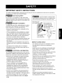 3
3
-
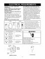 4
4
-
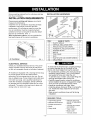 5
5
-
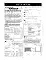 6
6
-
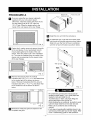 7
7
-
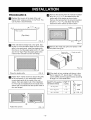 8
8
-
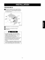 9
9
-
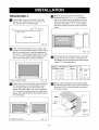 10
10
-
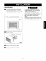 11
11
-
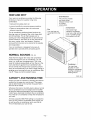 12
12
-
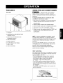 13
13
-
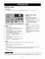 14
14
-
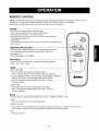 15
15
-
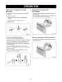 16
16
-
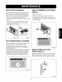 17
17
-
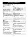 18
18
-
 19
19
-
 20
20
-
 21
21
-
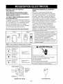 22
22
-
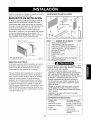 23
23
-
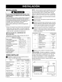 24
24
-
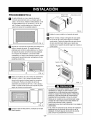 25
25
-
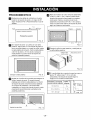 26
26
-
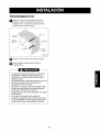 27
27
-
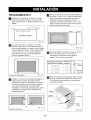 28
28
-
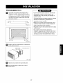 29
29
-
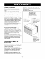 30
30
-
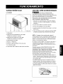 31
31
-
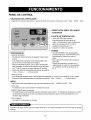 32
32
-
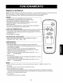 33
33
-
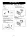 34
34
-
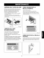 35
35
-
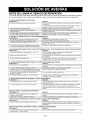 36
36
-
 37
37
-
 38
38
-
 39
39
-
 40
40


Kenmore 76105 El manual del propietario
- Tipo
- El manual del propietario
en otros idiomas
- English: Kenmore 76105 Owner's manual
Artículos relacionados
-
Kenmore 75135 501 Manual de usuario
-
-
Kenmore 580.75119500 El manual del propietario
-
-
Kenmore 580.73093300 El manual del propietario
-
-
-