
Owner's Manual
Manual del Propietario
®
THROUGH-THE-WALLAIRCONDITIONER
ACONDICIONADODEAIREA TRAVESDEPARED
ModeI, Modelo 580.74085 580.74124 580.74132
Sears, Roebuck and Co., Hoffman Estates, IL 60179 U.S.A.
www.sears.com

TABLE OF CONTENTS ........................2
WARRANTY ..............................................2
SAFETY .....................................................3
ImportantSafety Instructions...................... 3
ELECTRICAL REQUIREMENTS .......4
INSTALLATION ........................................5
Installation Requirements ......................... 5
Installation ................................................ 6
Procedure A ............................................. 7
Procedure B ............................................. 8
Procedure C........................................... 10
OPERATION ...........................................12
How and Why ......................................... 12
Normal Sounds ...................................... 12
Capacity and Running Time ................... 12
Features ................................................. 13
Using the Air Conditioner ....................... 13
Control Panel ......................................... 14
Remote Control ...................................... 15
MAINTENANCE .....................................17
Air Filter Cleaning ................................... 17
Air Conditioner Cleaning ........................ 17
How to Remove the Front Grille ............. 17
How to Replace the Front Grille ............. 17
TROUBLESHOOTING .........................18
Before Calling for Service ...................... 18
ESPANOL ................................................2o
MASTER PROTECTION
AGREEMENTS ......................................39
SERVICE NUMBERS ............ Back Cover
FULL ONE YEAR WARRANTY ON
THROUGH-THE-WALL AIR CONDITIONER
For one year from the date of purchase, when this
air conditioner is operated and maintained for
normal room cooling according to instructions in this
owner's manual, Sears will repair this air
conditioner, free of charge, if defective in material or
workmanship.
FULL FIVE-YEAR WARRANTY ON
SEALED REFRIGERATION SYSTEM
For five years from the date of purchase, when this
air conditioner is operated and maintained for
normal room cooling according to instructions in this
owner's manual, Sears will repair the sealed
refrigeration system (consisting of refrigerant,
connecting tubing, and compressor), free of charge,
if defective in material or workmanship.
WARRANTY SERVICE IS AVAILABLE BY
CONTACTING SEARS SERVICE AT
1-800-4-MY-HOME ®.
Warranty coverage applies only to air conditioners
used for non-commercial, private household
purposes.
This warranty applies only while this product is in
use in the United States.
This warranty gives you specific legal rights, and
you may also have other rights which vary from
state to state.
Sears, Roebuck and Co., D/817WA,
Hoffman Estates, IL 60179 U.S.A.
-2-

IMPORTANT SAFETY INSTRUCTIONS
The safety instructions below will tell you how to use your room air conditioner to avoid harm to yourself or
damage to your ROOM AIR CONDITIONER.
V!_W:_:t_II_[_FOR YOUR SAFETY
Do not store or use gasoline or other flammable
vapors and liquids in the vicinity of this or any other
appliance. Read product labels for flammability and
other warnings.
PREVENT ACCIDENTS
To reduce the risk of fire, electrical shock, or injury
to persons when using your air conditioner, follow
basic precautions, including the following:
• Be sure the electrical service is adequate for the
model you have chosen.
• If the air conditioner is to be installed in a window,
you will probably want to clean both sides of the
glass first. If the window is a triple-track type with a
screen panel included, you may want to remove
the screen completely before installation.
• Be sure the air conditioner has been securely and
correctly installed according to the instructions in
this manual.
Save this manual and installation instructions for
possible future use in removing or reinstalling this
unit.
• Use gloves when handling the air conditioner.
Be careful to avoid cuts from sharp metal fins on
front and rear coils.
V!_W,.1;i_ll_[dELECTRICAL INFORMATION
The complete electrical rating of your new room air
conditioner is stated on the serial plate. Refer to the
rating when checking the electrical requirements.
• Be sure the air conditioner is properly grounded.
To minimize shock and fire hazards, proper
grounding is important. The power cord is
equipped with a three-prong grounding plug for
protection against shock hazards.
• Your air conditioner must be plugged into a
properly grounded wall receptacle. If the wall
receptacle you intend to use is not adequately
grounded or protected by a time delay fuse or
circuit breaker, have a qualified electrician install
the proper receptacle.
• Do not run air conditioner with packing sheet of
the back of the sleeve, and packing corner and
blue tape of the air conditioner. This could result in
mechanical damage within the air conditioner.
• Do not use an extension cord or an adapter
plug.
_ Avoid fire hazard or electric shock.
Do not use an extension cord or an adapter plug.
Do not remove any prong from the power cord.
Grounding type
wall receptacle
Do not under any
circumstances cut,
remove, or bypass
the grounding prong
from this plug.
grounding plug
ENERGY SAVING IDEAS
• The capacity of the room air conditioner must fit
the room size for efficient and satisfactory
operation.
• install the room air conditioner on the shady side
of your home. A window that faces north is best
because it is shaded most of the day.
• Do not block air flow inside with blinds, curtains, or
furniture; or outside with shrubs, enclosures, or
other buildings.
• Close the floor and wall registers and the fireplace
damper so cool air does not escape up the
chimney and into the duct work.
• Keep blinds and drapes in other windows closed
during the sunniest part of the day.
• Clean the air filter as recommended in the
MAINTENANCE section of this manual.
• Proper insulation and weather stripping in your
home will help keep warm air out and cool air in.
• External house shading with trees, plants or
awnings will help reduce the air conditioner's work
load.
• Operate heat producing appliances such as
ranges, washers, dryers, and dishwashers during
the coolest part of the day.
-3-

OBSERVEALL LOCAL CODES AND
ORDINANCES.
DO NOT, UNDER ANY CIRCUMSTANCES,
REMOVE THE POWER SUPPLY CORD
GROUND PRONG.
ELECTRICAL GROUND IS REQUIRED ON
THIS APPLIANCE.
A 208/230-volt 60 Hz, AC only, 15A fused and
properly grounded electrical supply is required.
A time delay fuse or time delay circuit breaker
is recommended. Use a dedicated circuit,
serving only this appliance.
DO NOT USE AN EXTENSION CORD.
RECOMMENDED GROUNDING METHOD
For your personal safety, this appliance must
be grounded. This appliance has a power
supply cord with a 3-prong grounding plug. To
minimize possible shock hazard, the cord must
be plugged into a mating grounding type wall
receptacle and grounded in accordance with
the National Electrical Code (ANSt/NFPA 70)
latest edition and all local codes and
ordinances. If a mating wall receptacle is not
available, it is the personal responsibility and
obligation of the customer to have a properly
grounded 3-prong wall receptacle installed by a
qualified electrician.
Electrical Shock Hazard
Plug into a grounded 3 prong outlet.
Do not remove ground prong.
Do not use an adapter.
Do not use an extension cord.
Failure to follow these instructions can result
in death, fire, or electrical shock.
Ground
prong I/! _ 'fl
/ 3-prong
_..k I \"--J I grounding
,J-prong _ I _ ] type wall
gg.rounalng k _'T'F I receptacle
Power_ "_
supply
cord
-4-

Remove packing materials from the wall sleeve and tape
from the air conditioner.
INSTALLATION REQUIREMENTS
If you use an existing wall sleeve, you should
measure its dimensions.
Install the new air conditioner according to these
installation instructions to achieve the best
performance. All wall sleeves used to mount the
new air conditioner must be in good structural
condition and have a rear grille to securely attach
the new air conditioner. (FIG. 1)
With the Kenmore sleeve, you can maintain the
best performance of the new air conditioner. (FIG. 2)
20-3/32"
(511 ram)
6 ram)
Air Conditioner
8-_5/s2"(468ram)
FIG. !
INSTALLATION HARDWARE
ptions
ITEM
\)
NAME OF PARTS Q'TY
i PLASTIC GRILLE 1
i VERTICAL INSULATION STRIP 1
INSULATION STRIPS 2
HORIZONTAL INSULATION STRIP 1
AROUND
SUPPORT BLOCK 2
i BAFFLE 1
ii TRIM FRAME 2
SHIM 2
i PLASTIC NUTS AND WASHER SCREWS 4
i GRILLE REAR 1
Expanded
aluminum metal grill
(394mm}
Kenmore Wall Sleeve FIG. 2
ELECTRICAL SERVICE
Check your available electrical service. The power
supply available must be the same as that shown
on the unit nameplate (found on left side of cabinet).
All models are equipped with a 3-prong service plug
to provide proper service and safe positive
grounding. Do not change plug in any way. Do not
use an adapter plug. If your present wall outlet does
not match your plug, call a qualified electrician to
make the necessary corrections. SAVE CARTON
for storage and this OWNER'S MANUAL for future
reference. The carton is the best way to store unit
during winter or when not in use.
-5-
To avoid risk of personal injury, property damage,
or product damage due to the weight of this
device and sharp edges that may be exposed:
•Air conditioners covered in this manual pose an
excessiveweight hazard. Two or more people
are needed to move and install the unit.
To prevent injury or strain, use proper lifting and
carrying techniques when moving unit.
• Carefully inspectlocation where air conditioner
will be installed. Be sure itwill support the weight
of the unitover an extended periodof time.
• Handle air conditioner with care. Wear
protective gloves whenever lifting or carrying the
unit. AVOID the sharp metal fins offront and
rear coils.
• Make sure air conditioner does not fall during
installation.
REQUIRED TOOLS:
• Tight Fitting gloves
• Standard screwdriver
• Phillips screwdriver
• Pliers
• Sharp knife
• 3/8-inch open end
wrench or adjustable
wrench
• 1/4-inch hex socket
and ratchet
• Tape measure
• Electric drill
• 1/4-inch drill bit

INSTALLATION
We strongly recommend the removal of the
oldwall sleeve and the installationof a new
Kenmore Wall Sleeve,
If you decide to keep the existing wall sleeve,
you haveto redirect the louvers at the back of the
wall sleeve illustration. The use of pliers is
recommended. If you DO NOT redirect,you run
the risk of poor performance or product failure.
This is not covered under the terms of the
Kenmorewarranty.
• Pick a location which will allow the conditioned air
to blow into the area you want. Good installation
with special attention to the proper position of the
unit will lessen the chance that service will be
needed.
ITEMS IN INSTALLATION HARDWARE
You may not need all parts in the kit. Discard
unused parts
ITEM (inches)
Plastic grille
Vertical insulation strip
Around insulation Strips
Horizontal Insulation Strip
Support Block
Baffle
Shim
Trim Frame
Washer Screw
Nuts(Plastic)
Grille Rear
263/4 X 161/2
158/18 X 13/8X 13/8
671/8 X 13/8 X 25/32
5927/32 X 13/8 X 13/8
237/32 X 13/8 X 13/I8
13/4 X 13/8 X 45/18
14 x 41/2 x 1/8
1113/18X 1 X3/4
Qty.
1
1
1
1
1
2
1
2
2
4
4
1
HOW TO INSTALL
H Identify the existing wall sleeve before installing
the unit from the listed below.
Wall Sleeve Dimensions (inches)
Brand
White-Westinghouse
Frigidaire
Carrier (52F series)
General Electric
/Hotpoint
Width
25-1/2
26
Whirlpool 25-7/8
Fedders/Emerson 27
Sears/Kenmore 25-7/8
Emerson/Fedders 26-3/4
Carrier (51S Series) 25-3/4
Friedrich 27
Height Depth
15-1/4 16, 17-1/2
or 22
15-5/8 16-7/8
17-1/8
16-1/2
or 23
16-3/4 16-3/4
or 19-3/4
15-17/32 16-23/32
15-3/4 15
16-7/8 18-5/8
16-3/4 16-3/4
NOTE: All wall sleeves used to mount the new Air
Conditioner must be in sound structural condition
and have a rear grille that securely attaches to
sleeve, or rear flange that serves as a stop for the
Air Conditioner.
_-'_ Remove old air conditioner from existing wall
sleeve.
_1 Clean the interior of an existing sleeve.
(Do not disturb seals.)
D Wall sleeve must be securely fastened in wall
before installing the air conditioner. Use the
nails or screws through sleeve into wall, if
needed. Repaint sleeve if needed.
_4J Prepare the wall sleeve for installation of the
unit. If you plan to use your existing wall sleeve,
and it is not Kenmore, use procedure B or C
below.
Procedure Brand Depth(inches)
A Sears/Kenmore 16-23/32
White-Westinghouse
Frigidaire Carrier 16, 17-1/2
or 22
(52F series)
B General Electric
16-7/8
/Hotpoint
Whirlpool 17-1/8 or 23
Carrier (51S series) 18-5/8
16-3/4
Fedders/Emerson
or 19-3/4
C
Emerson/Fedders 15
Friedrich 16-3/4
Q Install new unit into wall sleeve.
CAUTION: The sleeve must be installed with a
slight downward slope as shown so that water can
drain outside.
LINTEL
(PURCHASED LOCALLY)
INSIDE_=sope _OUTSIDE FRONT UNIT Wall Sleeve
2..rvli,_i,TiumII II _ _"Mini ...... 1i4" _ _" .....
UNIT INSTALLATION
{MORTAR)
INSTALLATION OF SLEEVE
INTO PRE CAST CONCRETE
OR MASONRY WALL
SLEEVEiNSTALLATION FIG. 3
-6-

PROCEDURE A
_1 If you are using the new sleeve supplied with
your unit, skip to step 3. Otherwise, install the
plastic grille from the kit. Cut the plastic grille to
25-1/2" wide and 15-1/4" high. Place the
plastic grille to the inside of the wall sleeve at
the rear flange.
FIG. 4
_"_ Fasten the 4 washer screws to secure the grille
to the wall sleeve. If you need plastic nuts to
mount plastic grille to the inside of the wall
sleeve, there are plastic nuts in the installation
kit. The nuts are installed from the inside of the
sleeve and are pressing into the square holes
of the rear flanges.
or
FIG. 5
_J Remove the backing from the Vertical
Insulation strip 158/18 x 13/8 X 13/8and attach that
to the inside right of the sleeve as shown
below. Remove the backing from the Around
Insulation strip 671/8 x 13/8X 25/32 and attach that
to the inside front of the sleeve as shown
below.
grille will minimize the recirculation of hot
discharge air.
Plastic rear grille
Steel rear c
FIG. 7
_4J Install the new unit into the wall sleeve.
r_To assemble trim, snap the tab of each piece
into the slot of the other piece as shown below.
Slide trim over the front of the air conditioner
until trim is flush with sleeve as shown below.
Trim (2 ea)
Wall
"I
/
FIG. 8
FIG. 6
D If you wish to keep the unit be operated at higher
performance state, remove the steel rear grille
and attach the plastic rear grille. The plastic rear
•Air conditioners covered in this manual pose
an excessive weight hazard. Two or more
people are needed to move and install the unit.
To prevent injury or strain, use proper lifting
and carrying techniques when moving unit.
•When handling the air conditioner, be careful
to avoid cuts from sharp metal fins on front and
rear coils.
• Make sure air conditioner does not fall during
removal.
-7-

PROCEDURE B
H Redirect the louvers at the back of the wall
sleeve to 60 ° angle as shown in the FIG 9. The
use of pliers is recommended.
Rear Louvers
(Top View)
7 3132"
:_0 °
FIG. 9
I_lf the wall sleeve already has a rear grille, skip
to step 4. If the wall sleeve does not have a rear
grille or Iouvered panel, install the plastic grille
from the kit. Cut the plastic grille to 25-1/2" wide
and 15-1/4" high. Place the plastic grille to the
inside of the wall sleeve at the rear flange.
Place the plastic grille
FIG. 10
I[_ Fasten the 4 washer screws to secure the grille
to the wall sleeve. If you need plastic nuts to
mount plastic grille to the inside of the wall
sleeve, there are plastic nuts in the installation
kit. The nuts are installed from the inside of the
sleeve and are pressing into the square holes
of the rear flanges.
or
Fasten the screws
FIG. 11
I_ Remove the backing from the Vertical Insulation
strip 159/18 x 13/8x 13/8 and attach that to the
inside right of the sleeve as shown below.
Remove the backing from the Around Insulation
strip 671/8 x 13/8 X 25/32 and attach that to the
inside front of the sleeve as shown below.
FIG. 12
I_lf you wish to keep the unit be operated at
higher performance state, remove the steel rear
grille and attach the plastic rear grille. The
plastic rear grille will minimize the recirculation
of hot discharge air.
Plastic rear gritle
Steet rear (
FIG. 13
ir_lf the depth of your existing wall sleeve is less
than or equal to 18", skip to step 7. Otherwise,
cut the baffles and the support blocks according
to length "A" in the table below.
Depth"D"oftheexisting
wallsleeve(inches)
18 <D_<18-%
18-5/8 <D <19-3/4
19-3/4<D _<22
Length"A"
(inches)
3/4
1-3/4
4
_ upport
Block
1_[ - Baffle
FIG. 14
-8-

PROCEDURE B
WRemove the backing from the support blocks
and attach them to the inside of the wall sleeve
as shown FIG 15. Slide the baffle into slots of
the support blocks.
(7 3/32")
Wall
Wall
Sleeve
Block
f_ Install the new unit into the wall sleeve.
Q Assemble trim as described in Step 6,
Procedure A.
FIG. 15
-9-

PROCEDURE C
H Redirect the louvers at the back of the wall
sleeve to 60 ° angle as shown in the FIG 16.
The use of pliers is recommended.
73/32"
Lt0°
Rear Louvers
(Top View)
FIG. 16
I_lf the wall sleeve already has a rear grille, skip
to step 4. If the wall sleeve does not have a rear
grille or Iouvered panel, install the plastic grille
from the kit. Cut the plastic grille to 26-1/2" wide
and 15-1t2" high. Place the plastic grille to the
inside of the wall sleeve at the rear flange.
Place the plastic grille
FIG. 17
I[_ Fasten the 4 washer screws to secure the grille
to the wall sleeve. If you need plastic nuts to
mount plastic grille to the inside of the wall
sleeve, there are plastic nuts in the installation
kit. The nuts are installed from the inside of the
sleeve and are pressed into the square holes of
the rear flanges.
or
Fasten the screws FIG. 18
_J Remove the backing from the Horizontal
insulation strip 237/82 x 13/8 x 13/18and attach
that to the inside right of the sleeve as shown
below. Remove the backing from the Around
insulation strip 5927/32 x 13/8 x 13/8 and attach
that to the inside front of the sleeve as shown
below.
FIG. 19
El
If the depth of your existing sleeve is less than
or equal to 18", skip to step 7. Otherwise, cut
the baffles and the support blocks according to
Length "A" in the table below.
Depth"D"oftheexisting
wailsleeve(inches)
18 <D_<18-%
18-5/8<D <19-3/4
19-3/4<D _<22
Length"A"
(inches)
3/4
1-8/4
4
_ upport
Block
'_F Baffle
IG. 20
ir_ Remove the backing from the support blocks
and attach them to the inside of the wall sleeve
as shown FIG 21. Slide the baffle into slots of
the support blocks
Wall
Wall
Sleeve
7 3'32")
/ _ Block
FIG. 21
-10-

PROCEDURE C
W Remove the backing from the 1113/16" shim
strips and attach them as shown below in Fig.
23. The higher portion of shim is to be placed
in front of the rib on the base of wall sleeve.
h,4--' 'I'"0h
FIG. 22
I 6"1
FIG. 23
D If you wish to keep the unit be operated at
higher performance state, remove the steel rear
grille and attach the plastic rear grille. The
plastic rear grille will minimize the recirculation
of hot discharge air.
Plastic rear grille
Steel rear
FIG. 24
_'_ Install the new unit into the wall sleeve
_1_ Assemble trim as described in Step 6,
Procedure A.
-11-

HOW AND WHY
Your room air conditioner provides the following
functions to make hot weather living more
comfortable:
• Cools and circulates room air.
• Lowers humidity by removing excess moisture.
• Filters out summertime dust, dirt, and some
airborne impurities.
The air conditioner performs these functions by
drawing room air through a filter which traps dust
and dirt particles. The air then passes over a
cooling coil which refrigerates the air and removes
excess moisture. The same air is then returned to
the room- cooler, drier, and cleaner. Moisture
removed from the room air is carried to the outside
and evaporated.
Your air conditioner is designed to be easy to
operate and to provide plenty of cooling power.
NORMAL SOUNDS FIG.25
Aside from the regular fan motor and compressor
sounds coming from your air conditioner, you will
once in a while hear a pinging sound. This is the
result of moisture being picked up from the air in the
room and thrown against the air conditioner's fan.
This is normal and should not be cause for concern.
Also, do not be alarmed if you hear a slight hissing or
gurgling sound coming from your air conditioner after
it is off. These are normal coolant noises.
CAPACITY AND RUNNING TIME
Proper unit size is important in deciding the desired
comfort for the area you want to cool. The proper
size is determined by the number of square feet in
the area to be cooled.
Whenever the heat or humidity load is above normal
the air conditioner must run longer and more often
to keep the desired temperature you have selected.
Under heavy heat load conditions the air conditioner
may need to run constantly to keep the temperature
you want.
At times using the MED FAN setting to circulate the
room air may make it comfortable even though you
do not have the air conditioner set to cool the air.
This will decrease your cost of use.
Unit Vibration
The unit may vibrate
and make noise
because of poor wall
or window
construction.
Compressor
Fan The modern high
You may hear air efficiency compressor
movement from the may have a high pitched
fan. hum or pulsating noise
that cycles on and off.
Condenser
You may hear
droplets of water
hitting the condenser
causing a pinging or
clicking sound.
FIG. 25
-12-

FEATURES
THE UNIT
6 3 7 2 8 4 5 1 FIG.26
1. CABINET
2. HORIZONTAL AIR DEFLECTOR LEVER
(Vertical Louver)
3. VERTICAL AIR DEFLECTOR
(Horizontal Louver)
4. AIR DISCHARGE
5. FRONT GRILLE
6. INLET GRILLE (Air intake)
7. AIR FILTER
8. VENT CONTROL
THE SLEEVE AND THE REAR GRILLE
FIG. 27
USING THE AIR CONDITIONER
V!_'_'I-'_;]_II_[_I To reduce the risk of fire, electric
shock, or injury to persons, read the important
SAFETY instructions section before operating this
appliance.
To begin operating the air conditioner after
installation, follow these steps:
1. Plug in the air conditioner. (To prevent electrical
hazards, do not use an extension cord or an
adapter plug.)
2. Set the TEMP control to the coolest setting.
3. Set the MODE control at the highest COOL level.
4. Adjust the louvers for comfortable air flow.
5. Once the room has cooled, adjust the TEMP and
MODE control to the setting you find most
comfortable.
NOTE : If the air conditioner is turned off, wait 3
minutes before restarting. This allows pressure
inside the compressor to equalize. Failure to wait 3
minutes before restarting may cause inefficient
operation.
If you move the TEMP control to a warmer, then
immediately back to a cooler setting, the unit will
shut off. Wait 3 minutes before restarting.
Refer to the AIR CONDITIONER FEATURES
section for other settings.
VENT CONTROL
The Vent Control allows the air conditioner to either
recirculate inside air (CLOSE) or exhaust air to the
outside (OPEN). (FIG. 28)
• The CLOSE position is used when maximum
cooling is desired. It may also be used for air
recirculation without cooling when the air
conditioner is set in the FAN position.
• The OPEN position removes stale air from the
room and exhausts it to the outside. Fresh air is
drawn into the room through your home's normal
air passages.
• The OPEN or CLOSE position can be used with
any fan selection.
9. SLEEVE ASSEMBLY
(including Expanded Aluminum Rear grille)
10. REAR GRILLE
(Expanded Aluminum Rear grille)
PULL OPEN / PUSH CLOSE
FIG. 28
-13-

CONTROLPANEL
_FAN SPEED
• Everytime youpushthisbutton,itadvancesthesettingasfollows:{High-* Low-* Med-* High}
Applied to 580.74085, 580.74124
(-TIMER
- SHUT-OFF TIME
• You will usually use shut-off time while you sleep.
• If unit is running, use Timer to set number of hours
until shut-off.
• For your sleeping comfort, once Time is set, the
Temperature setting will raise 2°F after 30 rain.,
and once again after another 30 min.
• Push Timer button to advance setting from 1Hour
-* 2Hours -* ... -_ 12Hours maximum.
- START TIME
• If unit is off, Timer sets number of hours before unit
starts.
• PushTimer button to advance setting from 1Hour
-, 2Hours -, ...-, 12Hours maximum.
REMOTE CONTROL SIGNAL
RECEIVER
TEMPERATURE SETTING
• Usethis buttonto automaticallycontrolthe
temperatureofthe room.
Thetemperaturecanbe setwithina range
of60°Fto 86°Fbyincrementsof 1°F.
• Thesettingappearsin thedisplay.
POWER
• To turn the air conditioner ON, push this
button.
To turn the air conditioner OFF, push the
button again.
• This button takes priority over any other
button.
• When you first turn it on, the unit is in
cool mode, High fan speed, Temperature
setting at 72°F.
- AUTO RESTART
• In the event at a power failure, the unit
will run at the previous setting once
power returns.
MODE
- Push this button to shift mode of operation from COOL -_ ENERGY SAVER -_ FAN.
- ENERGY SAVER:
• The fan stops when the compressor stops cooling. Approximately every 3 minutes the fan will be turned
on so that the unit can check the room air temperature to determine if cooling is needed.
-14-

REMOTE CONTROL
NOTE: The Remote Control will not operate properly if strong light shines on the sensor window of the Air
Conditioner or if there are obstacles between the Remote Control and the Air Conditioner.
Every time you push button, you will hear a beep from the Air Conditioner.
POWER
• To turn the air conditioner ON, push this button.
To turn the air conditioner OFF, push the button again.
• This button takes priority over any other button.
• When you first turn it on, the unit is in cool mode, High fan speed,
Temperature setting at 72°F.
• Auto Restart
In the event at a power failure, the unit will run at the previous setting once
power returns.
TEMPERATURE SETTING
•Usethis buttontoautomaticallycontrolthetemperatureoftheroom.
Thetemperaturecanbe setwithina rangeof 60°Fto 86°Fby
incrementsof I°F.
•Thesettingappearsin thedisplay.
FAN SPEED
•Everytimeyou pushthis buttonit advancesthe settingasfollows:
(High -* Low -* Meal -* High)
TIMER
- SHUT-OFF TIME
• You will usuallyuse shut-off time while you sleep.
• If unit is running,use Timer to set number of hours until shut-off.
• For your sleepingcomfort,once Time is set,theTemperaturesettingwill
raise 2°F after 30 min, and once againafter another 30 min.
• Push Timer button to advance settingfrom 1Hour-+ 2Hours-+...-+
12Hours maximum.
- STARTTIME
•If unitisoff, Timersets numberof hoursbeforeunitstarts.
•PushTimer buttontoadvancesettingfrom 1Hour-+2Hours=,...=*
12Hoursmaximum.
Power
• Temp •
Fan Speed
I Timer Mode
MODE
- Push this button to shift mode of operation from COOL -* ENERGY SAVER -* FAN.
- ENERGY SAVER:
• The fan stops when the compressor stops cooling. Approximately every 3 minutes the fan will be turned on so
that the unit can check the room air temperature to determine if cooling is needed.
-15-

INSERTING THE REMOTE CONTROL
BATTERIES
1. Remove the cover from the back of the remote
controller.
2. Insert two batteries.
• Be sure that the (+) and (-) directions are
correct.
• Be sure that both batteries are new.
3. Reattach cover.
FIG. 29
• Do not use rechargeable batteries.
Make sure that both batteries are new.
• In order to prevent discharge, remove the batteries
from the remote control if the air conditioner is not
going to be used for an extended period of time
Keep the remote control away from extremely hot
or humid places.
To maintain optimal operation of the remote
control, the remote sensor should not be exposed
to direct sunlight.
• The remote control can be mounted on a wall
using the mountable holder.
FIG. 30
HORIZONTAL AIR-DIRECTION
ADJUSTMENT
• The horizontal air direction is adjusted by moving
vertical louver.
• The vertical louver control levers are located in the
right and left side of the air discharge.
FIG. 31
VERTICAL AIR-DIRECTION ADJUSTMENT
• The vertical air direction is adjusted by moving the
horizontal louvers.
FIG. 32
-16-

AIR FILTER CLEANING
The Air Filter will become dirty as it removes dust
from the inside air. It should be washed at least
every 2 weeks. If the Air Filter remains full of dust,
the air flow will decrease and the cooling capacity
will be reduced, possibly damaging the unit.
• Pull the inlet grille forward and pull out the air filter.
(FIG. 33)
• Wash the Air Filter under the faucet with warm
water. Be sure to shake off all the water before
replacing the filter. (FIG. 34)
FIG. 33 FIG. 34
AIR CONDITIONER CLEANING
Clean the front grille and inlet grille by wiping with a
cloth dampened in a mild detergent solution.
The cabinet may be washed with mild soap or
detergent and lukewarm water, then polished with
liquid appliance wax.
To ensure continued peak efficiency, the condenser
coils (outdoor side of the unit) should be checked
periodically and cleaned if they become clogged
with soot or dirt from the atmosphere. Brush or
vacuum exterior coils to remove debris from fins.
.... i
FIG. 35
HOW TO REMOVE THE FRONT
GRILLE
• Open the inlet grille.
• Remove the screw securing the Front Grille.
• Push the grille up from the bottom and pull the top
of the grille away from the case to lift the top tabs
out of their slots.
F
FIG. 36
HOW TO REPLACE THE
FRONT GRILLE
Attach the front grille to the cabinet by inserting the
tabs on the grille into the slots on the front of the
cabinet. Push the grille in until it snaps into place.
FIG. 37
-17-

BEFORE CALLING FOR SERVICE
Check the following list to be sure a service call is really necessary. A quick reference to this manual may
help you avoid an unneeded service call.
THE AIR CONDITIONER WILL NOT OPERATE
Check if... Then...
Wail plug disconnected.
House fuse blown or circuit breaker tripped.
Power is OFF.
Unit was turned off andthen ontoo quickly.
TEMP Control set warmer than room temperature.
Push piug firmly into wail outiet.
Replace fuse withtime delay type or reset circuit breaker.
Push the power button.
Set unit off and wait 3minutes before restarting.
Set TEMP Control to a lower number.
AIR FROM UNIT DOES NOT FEEL COLD ENOUGH.
Check if... Then...
FAN SPEED set at LOW. Push FAN SPEED button to set at HI.
TEMP Control set too warm. Set TEMP Control to a lower temperature.
Room temperature below 70°F (21°C). Cooling may not occur untilroom temperature rises above 70°F (21°C).
Temperature sensing tube touching evaporator coil, Straighten tube away from evaporator coil.
located behind front grille.
THEAIR CONDITIONERCOOLING, BUT ROOM ISTOO WARM- ICE FORMING ONCOOLING COIL BEHIND INLETGRILLE.
Check if... Then...
Outdoor temperature below 70°F (21°C). To defrost the coil,set the MODE to FAN, FAN speed to High.
Air filter may be dirty. Clean airfilter. Refer to Maintenance section of owner's manual.
To defrostthecoil, setthe MODE to Cool, Fan speed to high, and the
TEMP Control set too tow. Temp control to a higher temperature.
THEAIRCONDITIONERCOOLING, BUTROOM18TOOWARM
Check if... Then...
Dirty air filter- air restricted. Clean airfiIter. Refer to Maintenance section of owner's manual.
TEMP Control set too warm. Set TEMP Control to a lower temperature.
Front of unit is biocked by drapes, blinds, furniture, etc. Clear blockage in front of unit.
Air distribution is restricted.
Doors, windows, registers, etc. open. Cold air escapes. Close doors, windows, registers, etc.
Unit recentlyturned on in hot room. Aliowadditionaltimetoremovestoredheatfromwalls,ceiling,floor,andfurniture.
THE AIR CONDITIONER TURNS ON AND OFF RAPIDLY.
Check if... Then...
Outside temperature is extremely hot. [ Set FAN SPEED on HiGH to minimizethe cooling load. [
NOISE WHEN UNIT IS COOLING.
Check if... Then...
Soundoffan hittingwater- fromthe moistureremovalsystem. This is normal when humidity ishigh. Ctose doors,windows, and registers.
Window vibration - poor installation. Refer to nsta aton nstruct ons or check w th nsta er.
WATER DRIPPING INSIDE ROOM WHEN UNIT IS COOLING.
Check if... Then...
The air conditioner is improperly installed. Tiltinstallationair conditionerinstructionsslightlyor tocheckthe outsidewith installer,to allow water drainage. Refer to
WATER DRIPPING OUTSIDE WHEN UNIT IS COOLING.
Check if... Then...
The unit is removing large quantities of moisture This is normaIduring excessively humid days.
from humid room.
-18-

-19-

JNDICE ......................................................20
GARANTIA ..............................................20
SEGURIDAD ...........................................21
Instrucciones importantes de seguridad ...21
REQUISlTOS ELECTRICOS .............22
INSTALACION ........................................23
Requisitos de instalacion ....................... 23
Instalacion .............................................. 24
Procedimiento A ..................................... 25
Procedimiento B..................................... 26
Procedimiento C ..................................... 28
FUNCIONAMIENTO .............................30
C6mo y por que ...................................... 30
Sonidos normales .................................. 30
Capacidad y tiempo de funcionamiento ....30
Caracteristicas ....................................... 31
Uso del aparato de aire acondicionado .....31
Caracteristicas del aparato de aire
acondicionado ........................................ 32
MANTENIMIENTO ................................35
Limpieza del filtro de aire ....................... 35
Limpieza del aparato de aire
acondicionado ........................................ 35
Como extraer la rejilla frontal ................. 35
Como volver a colocar la rejilla frontal ...35
RESOLUClON DE PROBLEMAS....36
Antes de Ilamar al servicio tecnico ......... 36
ACUERDOS DE PROTECCION
ESPECIALIZADA ..................................39
NUMEROS DE SERVICIO
TleCNICO ..................................Contraportada
GARANTIACOMPLETADE UNANODEL
APARATODE AIREACONDICIONADODE
PARED
Duranteunafio,a contara partirdelafechadecompra,cuando
esteaparatodeaireacondicionadofuncioneparaelenfriamiento
normaldeunahabitaciony recibamantenimiento,todoello
seg@lasinstruccionesdeesteManualdelpropietario,Sears
repararaesteaparatodeaireacondicionado,deformagratuita,si
tuvieraalgundefectodefabricaciono materiales.
GARANTIACOMPLETADE ClNCOANOS DEL
SISTEMASELLADODE REFRIGERACION
DurantecincoaRosa contarapartirdela fechadecompra,
cuandoesteaparatodeaireacondicionadofuncioneparael
enfriamientonormaldeunahabitaci6ny recibamantenimiento,
todoellosegQnlasinstruccionesdeesteManualdelpropietario,
Searsreparar_,elsistemaselladoderefrigeracion(queconsiste
enIfquidoderefrigeracion,tubosdeconexiony compresor),de
formagratuita,situvieraalgundefectodefabricaciono
materiales.
ELSERVIClO DEGARANTfAPUEDE
CONTACTARSEENEL SERVIClODEATENClON
AL CLIENTE DESEARSEN EL1-800-4-MY-HOME%
Lacoberturadeestagarantfase aplicasolamenteaaparatosde
aireacondicionadoutilizadosdeformanocomercial,encasas
particulares,
Estagaranfiaseaplicasoloduranteelusodeesteproductoen
losEstadosUnidos.
Estagaranfialeconcedederechoslegalesespedficosy puede
queustedtengaotrosderechosadicionalesquevarfansegQnel
estado.
Sears,Roebuck and Co., D/817WA,Hoffman
Estates,IL 60179 EE.UU.
- 20 -

INSTRUCCIONES IMPORTANTES DE SEGURIDAD
Las instrucciones de seguridad que se indican abajo le diran c6mo utilizar su aparato de aire acondicionado
para evitar daSos a sf mismo y daSos a su APARATO DE AIRE ACONDIClONADO.
PARA SU SEGURIDAD
No almacene ni utilice gasolina ni otros Ifquidos ni gases
inflamables cerca de este uotro electrodomestico. Lea
las etiquetas de los productos para conocer su
inflamabilidad y otras advertencias.
EVITAR ACCIDENTES
Parareducirel riesgode incendio,electrocuci6noheridasa
personasal utilizarsu aparatodeaire acondicionado,siga
lasprecaucionesbasicas,incluyendolas siguientes:
• Asegt_resedequeel servicioelectricoesadecuadopara el
modeloque haescogido.
• Si el aire acondicionadova ainstalarseen unaventana,
serfaconvenienteque limpiaraprimeroambos ladosdel
cristal. Si laventanatienetres guias de deslizamiento,con
un panelpantallaincluido,puedeque deseeextraer
completamentelapantallaantesdela instalaci6n.
• Asegt_resedequeel aparatode aireacondicionadose ha
instaladode modoseguroy correctosegtJnlas
instruccionesen este Manual.Guardeeste manualy las
instruccionesde instalaci6nparasuposibleusofuturepara
extraerovolvera instalaresta unidad.
• Utiliceguantescuando manejeel aparatode aire
acondicionado.Presteatenci6nparaevitarcortesde las
afiladasaletasde metalen lasbobinasfrontaly posterior.
INFORMAClON ELI_CTRICA
Elvalornominalelectricocompletodesunuevoaparatode aire
acondicionadoseespecificaensuetiquetaidentificativa.
Consulteel valornominalal comprobarlos requisitoselectricos.
• Asegt]resedeque el aparatode aireacondicionadotiene
unatomade tierraadecuada.Para reduciral minimoel
riesgode electrocuciony de incendio,es importantetener
unatomade tierraadecuada.El cabledealimentaci6nest_
equipadoconun enchufedetres clavijascontomaa tierra
para protegercontra electrocuci6n.
• Su aparatodeaireacondicionadodebeestarenchufadoa
un enchufede paredconuna tomadetierra adecuada.Si
el enchufe que quiereutilizarno tiene unatoma detierra
adecuadao noest,. protegidoporunfusibletemporizadoo
un interruptordecorriente, hagaque unelectricista
cualificadoinstaleel enchufeapropiado.
• Nohagafuncionarel aparatode aireacondicionadocon la
I_minadeembalaje enla parte posteriordelalojamientoo
con lacintaazuly las esquinerasdelaparatode aire
acondicionado.Estopod@ tener comoconsecuenciala
producciondedahos[email protected]al aparatode aire
acondicionado.
• No utiliceuncableextensorni unenchufeadaptador.
_ Evitelospeligrosdeincendioodeelectrocuci6n.
Noutiliceuncableextensorniunenchufeadaptador.
Noquiteningunaclavijadelcabledealimentaci6n.
Receptaculo en
paredcon toma
de tierra
I Nunca corte, extraiga ni ]
haga unaderivaci6n que ]
evite la clavija de toma ]
de tierra de este /
enchufe. /
con toma de tierra
IDEAS PARA AHORRAR ENERGiA
• La capacidad del aparato de aire acondicionado debe
ser adecuada altamaho de la habitacion para un
funcionamiento eficaz y satisfactorio.
• Instale el aparato de aire acondicionado en el lado de su
hogara la sombra. Unaventana que mira al norte es la
mejor porque seencuentra a la sombra la mayor parte
del dfa.
• No bloquee el fiujo del aire en el interior con persianas,
cortinas o muebles, ni en el exterior con arbustos,
cercas u otros edificios.
• Cierre las aperturas en suelo y ventanas y el tirode la
chimenea para que el aire fifo no salga per la chimenea
ni per los conductos.
• Mantenga cerradas laspersianas y cortinas de otras
ventanas durante laparte mas soleada del dfa.
• Limpie el filtro de aire segL_nse recomienda en la
seccion de MANTENIMIENTO de este manual.
• El aislamiento adecuado y la preparacion de su hogar
para las condiciones atmosfericas mantendran el aire
caliente en el exterior y el aire fifo en el interior.
• La existencia de sombra en el exterior de la casa con
arboles, plantas otoldos reduce la carga de trabajo del
aparato de aire acondicionado.
• Haga funcionar los electrodomesticos que produzcan
calor, come cocinas, lavadoras, secadoras y lavavajillas,
durante la parte mas frfa del dfa.
-21 -

CUMPLA TODAS LAS NORMAS Y CODIGOS
LOCALES
NUNCA ELIMINE LA CLAVIJA DE TOMA DE
TIERRA DEL CABLE DE ALIMENTACION.
LA TOMA DE TIERRA ELI_CTRICA EN ESTE
ELECTRODOMESTICO ES NECESARIA.
Se necesita una alimentaci6n electrica de
208/230-volt 60 Hz, s61ode CA, con fusible de
15A y con una toma de tierra adecuada. Se
recomienda tambien que haya un fusible o
interruptor temporizado. Utilice un circuito
electrico dedicado s61oa este aparato.
NO UTILICE UN CABLE EXTENSOR.
METODO RECOMENDADO DE TOMA DE
TIERRA
Para su seguridad personal, este aparato debe
tener una toma de tierra. Este aparato tiene un
cable de alimentaci6n con un enchufe de 3
clavijas, una de elias para la toma de tierra.
Para reducir al minimo el riesgo de
electrocucidn, el cable debe estar enchufado
en un receptaculo de pared con toma de tierra
de acuerdo con la ultima edici6n del C6digo
nacional sobre electricidad (ANSI/NFPA 70) y
siguiendo todas las normas y directrices
locales. Si no esta disponible un receptaculo
de pared, es responsabilidad y obligaci6n
personal del cliente hacer que un electricista
cualificado instale un receptaculo en la pared
de 3 clavijas con una toma de tierra adecuada.
Riesgo de electrocuci6n
Enchufe en una toma de 3 clavijas con toma
de tierra. No elimine la clavija de toma de
tierra. No utilice un adaptador.
No utilice un cable extensor.
No seguir estas instrucciones puede tener
como consecuencia la muerte, un incendio o
electrocuci6n.
Cable de--
alimentacidn con
clavija dotada de
conexi6n a tierra
de 3 terminales.
Toma de corriente
de pared con
conexi6n a tierra.
_Terminal de
I conexion a tierra.
Bajo ninguna
circunstancia corte, quite o
evite el uso de la conexi6n
a tierra de esta clavija.
- 22 -

Quite los materiales de embalaje del alojarniento parr
paredy la cinta del aparato de aireacondicionado.
REQUISITOSPARALA INSTALACION
Si yaestausandounalojamientoparapared,midasus
dimensiones.
Instaleelnuevoaparatodeaireacondicionadodeacuerdocon
estasinstruccionesdeinstalacionparRIograrel mejor
rendimiento.TodoslosalojamientosqueseutilicenparRmontar
el nuevoaparatodeaireacondicionadodebenestarenbuen
estadoestructural.Suparrillaposteriordebeacoplarsecon
seguridadalnuevoaparato.(FIG.1)
Con elalojamientoKenmore,puedemantenerelmejor
rendimientodesunuevoaparatodeaireacondicionado.(FIG.2)
20-3/32"
(511 ram)
3/32_,
ram)
Aparatodeaireacondicionado FIG. 1
MATERIAL PARA LA INSTALACION
sdetarna_o
[_ 20pcionesdetarna_o
ART. NOMBREDELAPIEZA CANT.
_1_ PARRILLA DE PLASTICO 1
iBURLETE AISLANTE VERTICAL 1
_3} BURLETESDEAISLAMIENTOCIRCUNDANTES 2
44) iBURLETE AISLANTE HORIZONTAL 1
{5) BLOQUE DE SOPORTE 2
{6} iBAFLE 1
_(7_EMBELLECEDOR 2
_8} RECTIFICADOR 2
(.9} iTUEROASDEPLASTIC0YTORNILLOSDEARANDELA4
d0_ I:PARRILA, POSTERIOR 1
25-7/8"
(656 mm)
394 ram)
expandidafabricada
de alurninio
Alojamientode pared Kenmore
425mm)
FIG. 2
SERVIClO ELECTRICO
Verifiqueelservicioelectricodelquedispone.Laalimentacion
electricadisponibledebeserlamismaque laqueseindicaen la
placadenombre(queencontraraenla partederechadel
armazon).
Todoslosmodelosestanequipadosconunenchufedeservicio
detresclavijasqueproporcionaunservicioadecuadoy una
seguratomaa tierrapositiva.Nomodifiqueelenchufedeningun
modo.Noutiliceunadaptador.Sisutomadeparedactualno
coincideconel enchufe,diffjasea unelectricistacualificadoparR
efectuarlascorreccionesnecesarias.GUARDEELCARTON
parr almacenaresteMANUALDELUSUARIOyconsultarloenel
futuro.Elcartondelembalajeesel mejormododeguardarla
unidadduranteelinviernoocuandonosevayaa utilizar.
ParRevitarposiblesriesgosdelesionespersonales,dahosala
propiedadodaSosalproductodebidoalpesodeestedispositivo
ysusbordesafiladosquepuedenquedarexpuestos:
°Losaparatosdeaireacondicionadodelosquetrataeste
manualrepresentanunpeligrodepesoexcesivo.Senecesitan
dosomrspersonasparRmovereinstalarlaunidad.
ParRevitarlesionesoesguinces,usetecnicasdeelevaci6ny
transporteadecuadasalmoverlaunidad.
°Inspeccioneellugarenelqueseinstalaraelaparatodeaire
acondicionado.AsegQresedequesoportar&elpesodela
unidadaIolargodeunlargoperiododetiempo.
°Manipuleelaparatodeaireacondicionadoconcuidado.Lleve
guantesdeprotecci6nsiemprequelevanteotransportela
unidad.EVlTElasaletasmetalicaspuntiagudasdelasbobinas
frontalesyposteriores.
°AsegQresedequeelaparatodeaireacondicionadonosecae
durantelainstalaci6n.
HERRAMIENTASNECESARIAS:
*GUANTESDETRABAJO
APRETADOS
*DESTORNILLADORESTANDAR
*DESTORNILLADORTIPO
PHILLIPS
*ALICATES
*CUCHILLOAFILADO
*LLAVEINGLESADEEXTREMO
ABIERTODE3/8'0 LLAVEDE
CABEZAAJUSTABLE
TOMAHEXAGONALDE1/4
PULGADASYTRINQUETE
*CINTADEMEDIR
TALADRADORAELECTRICA
*BROCADETALADRARDE1/4"
-23-

INSTALACION
Recomendamosencarecidamentesacarelalojamiento
antiguoyqueseinstaleelnuevoalojamientodepared
Kenmore.
Sidecideseguirusandoel alojamientoactual,deber_t
redirigirlaspersianasdela parteposteriordelalojamiento.
Serecomiendausaralicates.SINOREDIRECCIONAlas
persianas,correelriesgodeobtenerunbajorendimiento
ofalloprematurodelproducto.
Estonoestercubiertoperlosterminosdelagaranfiade
Kenmore.
• Escojaunlugarenel queelaparatodeaireacondicionado
soplar_,al Areaquedesea.Unabuenainstalacionconespecial
atenci6na unemplazamientoadecuadodela unidadreducira
laposibilidaddenecesitarservicio.
ELEMENTOS DEL MATERIAL A INSTALAR
Talveznonecesitetodaslaspiezasquesesuministranenel kit.
Tirelas piezasnoutiiizadas.
ARTICULO(pulgadas)
Parrilladepl_.stico
Burletede aislamientovertical
Burletesdeaislamiento
circundante
Burletedeaislamientohorizontal
Bloquedesoporte
Bafle
Rectificador
Embellecedor
Tornillo de arandela
Tuercas (Pl_stico)
Parrilla,posterior
COMOINSTALAR
Cant.
263/4x 161/2 1
159/16x 13/3x 13/3 1
671/sx 13/3x 25/32 1
5927/32x 13/8x 13/3 1
237/32x 13/8x 13/16 1
13/4x 13/3x 45/16 2
14 x 41/2x 1/3 1
1113/16x 1 x3/4 2
2
4
4
1
H Antesde instalarlaunidad,identifiqueelalojamiento
(carcasa)actualenla listasiguiente.
Marca Dimensionesdelalojamientodepared(pulgadas)
White-Westinghouse
Frigidaire
Carrier(Serie52F)
GeneralElectric
/Hotpoint
Whirlpool
Fedders/Emerson
Sears/Kenmore
Emerson/Fedders
Carrier(Serie52F)
Friedrich
Ancho
25-1/2
26
25-7/8
27
25-7/8
26-3/4
25-3/4
27
Alto Largo
15-1/4 16, 17-1/2
or 22
15-5/8 16-7/8
17-1/8
16-1/2
or23
16-3/4 16-3/4
or 19-3/4
15-17/32 16-23/32
15-3/4 15
16-7/8 18-5/8
16-3/4 16-3/4
NOTA:Todoslosalojamientosqueseutilicenparamontarel
nuevoaparatodeaireacondicionadodebenestarenbuen
estadoestructuraly tenerunaparriilaposteriorqueseacople
conseguridadal alojamiento,ounapestaSaposteriorquesirra
detopealaparatodeaireacondicionado.
_"_ Quiteelviejoaparatodeaireacondicionadodelalojamiento
actual.
I_'1 Limpieel interiordelalojamientoactual.(Tengacuidado
paranomoverretenesnijuntas).
D EIalojamientodebeestaramarradoconseguridadala
paredantesdeprocederalainstalaciondelaparatodeaire
acondicionado.Uselosclavosotornillosatravesdel
alojamientoparaclavarenlapared,encasodenecesidad.
I_[_ Prepareelalojamientodeparedparala instalaciondela
unidad.Siplaneaseguirusandosualojamientodepared
actual,y noesun Kennmore,sigalasinstruccionesB oC
deabajo.
PrecedimientoMarca Largo(pulgadas)
A Sears/Kenmore 16-23/32
White-Westinghouse
FrigidaireCarrier 16,17-1/2
or22
Carrier(Serie52F)
B GeneralElectric
16-7/8
/Hotpoint
Whirlpool 17-1/8or23
Carrier(Serie51S) 18-5/8
16-3/4
Fedders/Emerson
or 19-3/4
C
Emerson/Fedders 15
Friedrich 16-3/4
r,_ Instalela nuevaunidadenelalojamientode pared.
PRECAUClON:Elalojamientodeberainstalarseconunaligera
inclinacionhaciaabajotalycomosemuestraparaqueel agua
3uedavaciarsehaciaafuera.
DINTEL
ADQUIRIR LOCALMENTE)
INTERIORMinimo2"] EXTERIORI___ 'Mi¸nim°FRONTAL1/4'INSTALAOION_UNIDADDEAl°jamient° deparedLAUNIDAD
_NS_k_OIONDELALOJAM_ENTO
ALOONC£ErO(HORMIGON)yAMOLOEN?O
0 PAREDDEkADRI&O
INSTALACION DEL ALOJAMIENTO FIG. 3
- 24 -

PROCEDIMIENTO A
O Si vaa usarel nuevoalojamientosuministroconsuunidad,
vayaalpaso3.DeIocontrario,instalelaparrilladeplastico
queencontraraenel kit.
Cortela parrilladeplasticoa25-1/2"deanchoy a15-1/4"
dealto.Coloquela parrilladeplasticoen elinteriordel
alojamientodeparedenlalengQetaposterior.
FIG. 4
_ Atornille los 4tornillos de arandela para asegurar la
parrilla alalojamiento de pared. Si necesita tuercas
de plastico para montar la parrilla de plastico en el
interiordel alojamiento, lasencontrar_,en el kit de
instalaci6n. Lastuercas se instalan desde el interior
del alojamiento y se presionan en los orificios
cuadrados de las lengeetas posteriores.
O FIG. 5
Quite el respaldodelburletede aislamientovertical 15
_'1 9/16x 13/8x 13/8y ac6pleloa la parteinteriorderecha
del alojamientocomosemuestraabajo.Qufteleel
respaldoalburletede aislamientocircundante671/8x 1
% x 25/32y acopleloala partefrontal interiordel
alojamientocomose muestraabajo.
FIG. 6
_'ISi desea mantenerla unidadfuncionandoenun estado
@time, quitela parrilla posteriory acoplela parrilla
posteriorde pl_stico.La parrillaposteriorde pl_.stico
reducir_al mfnimo la recirculaci6ndelairecalientede
descarga.
-25-
Parrillaposteriordeplastico
Parrillaposteriordeaceroinoxidable
FIG. 7
I_/'_ Instalela nuevaunidaden el alojamientode pared.
r,_ Paramontarel embellecedor,partala lengQetade cada
piezaen la ranurade la otrapiezacomesemuestraa
continuaci6n.Desliceel embellecedorper la parte
frontal delaparatode aire acondicionadohastaqueel
embellecedorquedeniveladoconel alojamientocome
seindicaen lailustraci6nde abajo.
Embellecedor
Pared
FIG. 8
Losaparatosdeaireacondicionadodelosquetrataeste
manualrepresentanunpeligrodepesoexcesivo.Se
necesitandosomaspersonasparamovereinstalarla
unidad.Paraevitarlastimarseo lesionarse,empleeunas
tecnicasdeelevaci6nytransporteadecuadasalmoverla
unidad.
AImanipularelaparatodeaireacondicionado,tenga
cuidadoyevitecortarseconlasaletasmetalicas
puntiagudasdela partefrontalylasbobinasposteriores.
Aseg_resedequeelaparatodeaireacondicionadonose
caedurantelaextracci6n.

PROCEDURE B
D Redirija las persianas de la parte posterior del
alojamiento a un _ngulo de 60° como se muestra
en la FIG 9. Se recomienda usar alicates.
7 3/32"
Persianas posteriores
(Mirando desde arriba)
FIG. 9
:_0 °
_Si el alojamiento de pared ya cuenta con una
parrilla posterior, vaya al paso 4. Si el
alojamiento de pared no tiene una parrilla
posterior ni panel apersianado, instale la parrilla
de plastico del kit. Corte la parrilla de plastico a
25-1/2" de ancho y a 15-1/4" de alto. SitQe la
parrilla de plastico en el interior del alojamiento
de pared en la pesta_a posterior.
Instale la parrilla de plastico
FIG. 10
_1 Atornille los 4 tornillos de arandela para
asegurar la parrilla al alojamiento de pared. Si
necesita tuercas de plastico para montar la
parrilla de plastico en el interior del alojamiento,
las encontrara en el kit de instalacion. Las
tuercas se instalan desde el interior del
alojamiento y se presionan en los orificios
cuadrados de las leng0etas posteriores.
Atornille
O
FIG. 11
_ Quitele el respaldo al burlete de aislamiento
vertical de 15 9/16 X 1 3/8x 13/8y ac6plelo a la
parte interior derecha del alojamiento como se
muestra abajo. Quitele el respaldo al burlete de
aislamiento circundante de 67 1/8x 13/8x 25/32y
ac6plelo al interior frontal del alojamiento como
se muestra abajo.
FIG. 12
_l_Si desea mantener la unidad funcionando en un
estado 6ptimo, quite la parrilla posterior y
acople la parrilla posterior de plastico. La
parrilla posterior de plastico reducira al minimo
la descarga de aire caliente de recirculacion.
Parrillaposteriorde plastico
Parrillaposteriorde aceroinoxidable
FIG. 13
Si el largo de su alojamiento de pared actual es
_"_ inferior o igual a 18", vaya al paso 7. De Io
contrario, corte los bafles y los bloques de
soporte de acuerdo con el largo "A" de la tabla
de abajo.
Pr0fundidad"D"delalojamiento
deparedyaexistente(pulgadas)
18 <D _<18-_/8
18-% <D_<19-3/4
19-3/4<D _<22
Longitud"A"
(pulgadas)
3/4
1-3/4
4
_ BI0que
desop0rte
_[_ Deflector
FIG. 14
- 26 -

PROCEDIMIENTO B
_aQcUftele el respaldo a los bloques de soporte y
6plelosen la parte interior del alojamiento de pared
come se muestra en la FIG15. Deslice el bafle en las
ranuras de losbloques de soporte.
Pared
Alojamiento
depared
Bloque
desoporte
FIG. 15
I[_1 Instale la nueva unidad en el alojamiento de pared.
I[_1 Instale el embellecedor come se describe en elpaso
6, Procedimiento A
-27-

PROCEDIMIENTO C
D Redirija las persianas de la parte posterior del
alojamiento a un angulo de 60° como semuestra en
la FIG 16. Se recomienda usar alicates.
60_
7 3/32_
Persianas posteriores
(Mirando desde arriba)
/_60 °
FIG. 16
_Si el alojamiento de pared ya cuenta con una parrilla
posterior, vaya al paso 4. Si el alojamiento de pared
notiene una parrilla posterior ni panel apersianado,
instale la parrilla de plastico del kit. Corte la parrilla
de plastico a 26-1/2" de ancho y a 15-1/2" de alto.
Coloque la parrilla de plastico en el interior del
alojamiento de pared, en lapestaha posterior.
Instale la parrilla de pl_.stico FIG. 17
_1 Atornille los 4 tomillos de arandela la
para asegurar
parrilla al alojamiento de pared. Si neeesitatuercas
de plastico para montar la parrilla de pl_.sticoen el
interiordel alojamiento, lasencontrara en el kit de
instalaci6n. Las tuercas se instalan desde el interior
del alojamiento y se presionan en los orificios
cuadrados de las lengOetasposteriores.
O
Atornille FIG. 18
_1_ Quftele el respaldo al burlete de aislamiento
horizontal 23 7/32 X 13/8x 1 3/16 y acoplelo a la parte
interiorderecha del alojamiento come se muestra
abajo. Quftele el respaldo al burlete de aislamiento
circundante 59 27/32x 13/8x 13/8 y ac6plelo a la
parte frontal interior del alojamiento come se
muestra abajo.
FIG. 19
I_','_ Si el largo de su alojamiento de pared actual es
inferior o igual a 18", vaya al paso 7. De Io
contrario, corte los bafies y los bloques de
soporte de acuerdo con el largo "A" de la tabla
de abajo.
Profundidad"U"delalojamiento
deparedyaexistente(pulgadas)
18 <D<18-%
18-%<D_<19-3/4
19-3/4<D_<22
Longitud"A"
(pulgadas) _- Bloque
3/4 _ de soporte
1-3/4 _[_ Deflector
4 _ FIG. 20
r,_ Quftele el respaldo a los bloques de soporte y
ac6plelos en la parte interior del alojamiento de
paredcome se muestra en la FIG21. Deslice el
bafleen las ranuras de los bloques de soporte.
Pared
Alojamiento
de pared
Soporte
frontal
FIG. 21
- 28 -

PROCEDIMIENTO C
W Quftele el respaldo a los burletesde 11 13/16"de los
rectificadores y ac6plelos abajo en la Fig. 23. La
porcion m_.salta del rectificador ha de colocarse
delante de la costilla, en la base del alojamiento.
, ]bA,to
FIG. 22
I 6"1
FIG. 23
_JSi desea mantener la unidad funcionando en un
estado optimo, quite la parrilla posterior y acople la
parriila posterior de piastico. La parrilla posterior de
pl_.sticoreducira al mfnimo la recirculacion del aire
caliente de descarga.
Parrillaposteriorde plastico
Parrillaposteriordeaceroinoxidable
FIG. 24
_'_ Instale la nueva unidad en el alojamiento de
pared.
instale el embeilecedor como se describe en el paso
_i]6, Procedimiento A
-29-

COMO Y PORQUE
Esteaire acondicionadoincluyeunmanualde instrucciones
parahacer mD.sagradableslas condicionesde habitabilidad
en estacionescalurosas.
• Refrigeray hacecircularel aire dela habitaci6n.
• Eliminala humedaden exceso.
• Losfiltroseliminanel polvoy la suciedadtipicas dela
estaci6n,asi comolas impurezasqueelairecontiene.
El aireacondicionadorealizalasfuncionesanterioresal
hacerpasarel airede la habitaci6na travesde unfiltro que
atrapalas partfculasde polvoy lasuciedad.A continuaci6n,
el aire pasa porunserpenfinde refrigeracionqueenfrfael
airey eliminala humedaden exceso.Elmismoairevolver_ia
la habitacionperom_s fifo, m_s secoy mD.slimpio.La
humedadque se ha eliminadodel airedela habitaci6nsale
al exteriory se evapora.
Esteaire acondicionadose hadiseflado paraqueseaf_cil
de utilizary paraqueproporcionela m_ximacapacidadde
refrigeraci6n.
SONIDOS NORMALES FIG.25
AdemD.sde lossonidosnormalesdelcompresory del motor
delventiladorqueprocedendel aireacondicionado,es
posibleque oiga devez en cuandoun sonidode silbidos.
Estose debeal sonidoque se producealrecogerla
humedaddelairede lahabitaci6ny expulsarlaatravesdel
ventiladordelaireacondicionado.Estesonidoesnormal,no
tieneporquepreocuparse.Tambienes posiblequese
escucheunsonidodesiseoo de borboteocuandoapagueel
aireacondicionado.Nodebealarmarse,ya quesonsonido
normalesque se producenal refrigerar.
Ventilador
Vibraciones
Es posible que la unidad vibre y
emita ruidos debido a la
construcci6n deficiente de las
paredes o de las ventanas.
Esposiblequeoigael
movimientodelventilador.
Compresor
Esposiblequeel moderno
compresorde alto
rendimientolancehumoo
emitaruidosdeforma
intermitente.
Condensador
Tambien es posible que
oiga gotas de agua caer
en el condensador dando
lugar a silbidos o clics.
FIG. 25
CAPACIDADY TEMPO DE
FUNCIONAMIENTO
Esimportanteestablecerla zonaquedesearefrigerarpara
decidiren consecuenciael tamaflo adecuadode la unidad.
Sutamaflo dependerAdelntJmerode metroscuadradosde
la zona que deseerefrigerar.
Si la cargade humedadoel calor es superioraIonormal,el
aireacondicionadose deberD,utilizar m&stiempoy con mD.s
frecuenciapara mantenerla temperaturaestablecida
deseada. Tambien esposibleque el calor seatan elevado
quetengaque utilizarel aireacondicionadoconstantemente
paramantenerlatemperaturadeseada.
Puedeutilizarel valor MED FAN(ventiladormedia)paraque
el aire de la habitacioncirculey hacerlas condicionesde
habitabilidadmD.sid6neas,aunqueno tengael aire
acondicionadoestablecidoen el modede refrigeraci6n.Asf
disminuirD,el costede utilizacion.
- 30 -

CARACTERISTICAS
LA UNIDAD
6 37284 5
1.CABINA
2. DEFLECTORDEAIREHORIZONTAL
(Persianavertical)
3. DEFLECTORDEAIREVERTICAL
(Persianahorizontal)
4. DESCARGADE AIRE
5. REJILLADELANTERA
6. REJILLADELANTERA(entradade aire)
7. FILTRODEAIRE
8. CONTROLDEVENTILACION
1 FIG. 26
ELMANGUITOY LAREJILLATRASERA
FIG.
UTILIZACIONDELAPARATODE
AIREACONDICIONADO
_Antes de utilizaresta unidad,lealas
instruccionesacerca dela seguridadparaevitarriesgosde
fuegos, sacudidaelectricao daflos a personas.
SigNestos pasosparaempezar autilizar elaire
acondicionadodespuesde su instalacion:
1.Conecteel aireacondicionado.(Paraevitarpeligros
electricosnoutilicealargaderasni adaptadores).
2.Establezcael controldetemperatura(TEMP)en elvalor mAs
frio.
3.Establezcael controldemodo(MODE)enel nivelmAsfrio.
4.Ajustelas persianasparaqueelflujode airele resulte
agradable.
5.Cuandola habitacionsehayaenfriado,ajusteel controlde
modoy temperaturaenel valorque leresultemas
agradable.
NOTA:Siel aireacondicionadoestaapagado,esperetres
minutosantesdevolveraencenderlo.Deestaformase
equilibralapresiondel interiordelcompresor.Si noesperatres
minutosantesdevolverloaencender,esposiblequese
produzeanfallosdefuncionamiento.
Sicambieel controldetemperaturaa mAstempladoy vuelvea
cambiarinmediatamenteaun valormAsfifo, launidadde
apagar&Esperetres minutosantesde volverloa encender.
Consultelasecciondefuncionesy caracteristicasdelaire
acondicionadoparaverotrosvalores.
CONTROL DE VENTILACION
Elcontroldeventilacionpermitequeel aireacondicionado
hagacircularel aire(CLOSE)oexpulseel aireal exterior
(OPEN).(FIG.28)
• La posicionCLOSEseutilizacuandodeseela maxima
refrigeracion.Tambienseutilizapararecircularel airesin
refrigerarcuandoelaireacondicionadoesteen laposicion
FAN(ventilacion).
• Enla posicionOPEN(abierto)eliminaelaireviciadode la
habitaciony Ioexpulsaal exterior.Elairefrescosalea la
habitacionatravesde losconductosdeairenormalesdela
casa.
• La posicionOPENoCLOSEsepuedeutilizarconcualquier
selecciondelventilador.
9. CONJUNTODELMANGUITO
(Rejillatraserade aluminioampliadainoluida)
10. REJILLATRASERA
(Rejillatrasera dealuminioampliada)
-31 -
TIREPARAABRIR/ EMPUJEPARACERRAR
FIG. 28

PANTALLA
-VELOCIDAD DE VENTILADOR(FAN SPEED)
•Cadavezqueoprimeestebot6n,laconfiguraci6ncambiasegt]nsigue:
{Alta *Baja *Media *Alta}({High*Low *Med *High})
580.74085, 580.74124
RECEPTOR DE SENAL DEL
CONTROL REMOTO
('-TEIVlPORIZADOR (TIMER)
- HORA DEAPAGADO
•Utilizaraamenudamentelahoradeapagadomientras
duerme.
•Conlaunidadenfuncionamiento,utiliceelTemporizador
parafijarelnumerodehorashastaelapagado.
•Parasucomodidadduranteelsueho,unavezfijadalaHera,
laTemperaturafijadaseelevara2°Fdespuesde30min.y
2°Fdespuesdeotros30min.
•CadavezqueoprimaelbotonTemporizador(Timer),lahera
fijadaavanzadelmodesiguiente:1hora *2horas *.... *
12horasmaximo.
- HORA DE ENCENDIDO
•Conlaunidadapagada,utiliceelTemporizadorparafijarel
nt]merodehorashastaelencendido.
•CadavezqueoprimaelbotonTemporizador(Timer),lahora
fijadaavanzadelmodosiguiente:1hora _2horas_....
12horasmaximo.
FIJACION DE TEMPERATURA (TEMP)
• Utiliceeste bot6nparacontrolar
automa.ticamentela temperaturade la
habitaci6n.La temperaturapuedefijarse
en un rangede 15,6°Ka 30°K(60°Fa
86°F)en incrementosde I°F.
ENCENDIDO (POWER)
• Paraencendedorel aparatode aire
acondicionado,oprimael bot6nON. Para
apagarel aparatodeaire acondicionado,
oprimael bot6nde nuevo.
• Estebot6ntiene prioridadsobrecualquier
otro.
• AIencenderlaper primeravez, la unidad
esta.en mododeenfriado,velocidadde
ventiladoralta,temperaturafijadaa 22°K
(72°F).
- REENCENDIDOAUTOMATICO
• Cuandovuelve la electricidaddespuesde
uncorte de suministroelectrico,la unidad
comenzaraa funcionarcon los01timos
valores en losque estabafuncionando
_- IVlODO (MODE)
- Cada vez que oprime este bot6n, cambiara entre FRJO(COOL), AHORRO DE ENERGJA(ENERGY
SAVER), VENTILADOR (FAN).
- AHORRO DEENERGJA(ENERGY SAVER)
• Elventilador se para cuando el compresor deja de enfriar. Aproximadamente cada 3 minutos el
ventilador se pondr_,en marcha y la unidad comprobar_,el aire de la habitaci6n para determinar si
necesita enfriarse.
- 32 -

CONTROL REMOTO
NOTA:Elcontrolremotenofuncionar_,demodoadecuadosi unaluzfuerteestabrillandosobrela pantalladelsensorenla unidadde
aireacondicionadoo siexistenobstaculosentreelControlremotoy elaparatodeaireacondicionado.
Cadavezqueoprimeunboton,seescuchara,unpitidoprocedentedelaparatodeaireacondicionado.
ENCENDIDO (POWER)
•Paraencenderelaparatodeaireacondicionado,oprimaelbotonON.Para
apagarelaparatodeaireacondicionado,oprimaelbotondenuevo.Esteboton
tieneprioridadsobrecualquierotro.
AIencenderperprimeravez,launidadest,.enmodedeenfriado,velocidadde
ventiladoralta,temperaturafijadaa2ZK (7ZF).
FIJACION DE TEMPERATURA (TEMP)
•Utiliceestebot6nparacontrolarautoma.ticamentelatemperaturadela
habitacion.Latemperaturapuedefijarseenunrangede15°K(60°F)a 30°K
(86°F)enincrementosdeI°F.
VELOCIDAD DE VENTILADOR (FAN SPEED)
•Cadavezqueoprimeestebot6n,elvalorfijadocambiasegt]nsigue:
{Alta *Baja*Media*Alta}(High*Low *Med *High)
TEMPORIZADOR (TIMER)
- HORADEAPAGADO
• Utilizaraamenudamentela horade apagadomientrasduerme.
•Conlaunidadenfuncionamiento,utiliceelTemporizadorparafijarelnumerode
horashastaelapagado.
•Parasucomodidadduranteelsueho,unavezfijadalaHora,laTemperaturafijada
seelevara2"Fdespuesde30min.y2"Fdespuesdeotros30min.
•Cadavezqueoptimaelbot6nTemporizador(Timer),laherafijadaavanzadelmode
siguiente:1hera _2 horas_.... _12horasm&ximo.
- HORADEENCENDIDO
•Conlaunidadapagada,utiliceelTemporizadorparafijarel n0merodehorashastael
encendido.
•Cadavezqueoprimaelbot6nTemporizador(Timer),laherafijadavariadelmode
siguiente:1hera _2 horas_.... _12horasmaximo.
Fan Speed
Timer Mode
MODO (MODE)
-Cada vez que oprimeestebot6n,cambiaraentreFR[O(COOL),AHORRODEENERGIA(ENERGYSAVER),
VENTILADOR(FAN).
- AHORRODEENERGIA
•Elventiladorseparacuandoelcompresordejadeenfriar.
Aproximadamentecada3minuteselventiladorsepondraenmarchaylaunidadcomprobaraelairedelahabitaci6npara
determinarsinecesitaenfriarse.
- 33 -

COLOCACION DE LAS PILAS DEL MANDO
A DISTANCIA
1. Extraiga la tapa de la parte trasera del control
remoto.
2. Inserte dos pilas.
• Asegt]rese de que los polos positivo (+) y
negativo (-) estan colocados correctamente.
• Asegt]rese de que ambas pilas sean nuevas.
3. Vuelva a colocar la tapa.
FIG. 29
AJUSTE DE LA DIRECCION HORIZONTAL
DEL AIRE
• Ladirecci6nhorizontaldel airese ajustemoviendola
persianavertical.
• Loselevadoresdelcontrolde la persianavertical se ubican
ala derechay ala izquierdadela descargadeaire.
FIG. 31
• Sinova autilizarel aireacondicionadoduranteunlargo
periododetiempo,quitelaspilasdelmandoadistanciapara
quenosedescarguen.Guardeelmandoadistancialejosde
lugaresextremadamentehOmedosocalurosos.Noexpongael
sensorremotoa laluzdirectadelsol paramantenerun
funcionamientooptimodelmandoadistancia.
• Elmandoadistanciase puedecolocarenla paredconun
soporte.
FIG. 30
AJUSTE DE LA DIRECCION VERTICAL DEL AIRE
• Ladirecci6nverticaldel airese ajustemoviendolas
3ersianashorizontales.
FIG. 32
- 34 -

LIMPIEZA DEL FILTRODE AIRE
Elfiltro de airese pedrO,ensuciaral quitar elpolvode la parte
interna.Sedeber_,lavaral menoscadadossemanas.Si el
filtro de airesigue estandosucio,el flujo deaire disminuiray
lacapacidadderefrigeraci6nsereducir_,produciendodaflos
en launidad.
• Empujela rejillade entradahaciadelantey saqueelfiltro
de aire.(FIG.33)
• Laveel filtrode airebajo el grifoconaguatemplada.
AsegOresedesacudirtodaelagua antesde volvera
colocarel filtro. (FIG.34)
FIG. 33 FIG. 34
LIMPIEZA DEL APARATODE AIRE
ACONDICIONADO
Limpiela rejilladelanteray la rejillade entradacon untrapo
humedecidoen unasoluci6nde detergenteneutro.La cabina
se debelimpiarcon unjab6no detergenteneutroy aguatibia
y, a continuaci6n,pulirlaconceraIfquida.
Paraasegurarla m_.ximaeficaciacontinua,sedeben
comprobary limpiarperiodicamentelos serpentinesdel
condensador(parteexternadela unidad)sise obstruyencon
hollfnosuciedadde la atm6sfera.Cepilleo aspirelos
serpentinesexterioresparaeliminarlos residues.
.... i
FIG. 35
COMO EXTRAER LA REJILLA
FRONTAL
• Abrala rejillade entrada.
• Quitelos tornillosque aseguranla rejilladelantera.
• Empujela rejillahacia arribadesdeabajoy saquela parte
superiorde larejillade la carcasapara levantarlas
pestaflassuperioresde las ranuras
FIG. 36
COMO VOLVERA COLOCAR LA
REJILLA FRONTAL
Acoplela rejilladelanteraa la cabinaintroduciendolas
pestaflas dela rejillaen lasranurasdela partedelanterade
la cabina.Presionesobre la rejillahastaqueencajeen su
sitio.
FIG. 37
-35-

ANTES DE LLAMAR PARA SERVICIO
Cheque la siguiente lista para asegurarse si en realidad es necesario Ilamar para servicio. Una referencia rapida a
este manual puede evitar una Ilamada para servicio innecesaria.
EL EQUIPO DE AIRE ACONDICIONADO NO FUNCIONA.
Elenchufenoestaconectadoenlatomadecorrientedepared. Conecteel enchufefirmementeenlatomadecorrientedepared.
Elfusibleeataquemadooelinterruptordecircuitose hadisparado. ReamplaceelfusibledaSadoconunfusibledeacoi6nretardadaoreajusteel
interrupterdecircuito.
Elaparatoestaapagado(OFF). Optimaelbot6ndeencendido.
Launidadse apag6y sevolvioaencenderdemasiadorapido. Apaguelaunidady espere3 minutosantesdevolveraencenderla.
ElcontroldetemperaturaTEMPse ajust6mascalidoquela Fieel controldeTEMPenunvalorinferior.
temperaturaambiente.
EL AIRE DE LA UNIDAD NO SALE BASTANTE FRIO.
VELOClDADDELVENTILADOR(FANSPEED)fiiadaenBAJA(LOW) OptimaelbotOndeVELOCIDADDELVENTILADOR(FANSPEED)parafijarlaenALTA(HI).
Controlde TEMPfiiado demasiadoalto. FijeelcontroldeTEMPaunvalorinferior.
Latemperaturadelahabitaci6neainferiora 70°F(21°C), Noseproducira,enfriamientohastaquelatemperaturadelahabitaci6nse
elevepotencimade70°F(21°0).
Eltubosensordetemperaturaeatatocandoelserpentfnfrfoqueeata Endereceeltubo alejandolodelserpentin.
situadodetrasdelfiltrodelaire.
ELAIREACONDICIONADOENFRJA,PEROLA HABITACIONSE SIENTEDEMASIADOCALIDA;SE FORMA
HIELOENELSERPENTINDEENFRIAMIENTODETRASDEL PANELDECORATIVOFRONTAL.
Latemperaturaexterioresinferiora70°F(21°C). Paradeacongelarla bobina,ajusteel MODOaVENTILACION,lavelocidaddel
ventiladorenAlta,VENTILElaVELOCIDADaAlto.
Elfiltrodelairepuedeeatarsudo. Limpieelfiltrodeaire.Consultelasecoi6nsobreMantenimientoensu Gufadel
Propietario.
Elcontroldetemperaturaseajust6demasiado. Paradeacongelarla bobina,fijeel MODO(MODE)a Frfo(COOL),lavelocidad
delventilador(FANSPEED)aAlta(HI)yelcontroldeTemperatura(TEMP)en
unvalormasalto.
EL AIRE AOONDIOIONADO ENFRIA, PERO LA HABITAOION SE SIENTE DEMASlADO CALIDA.
ElfiltrodelaireeatAsucioconIoqueserestringeelflujodelaire. Limpieelfiltrodelaire.Consultelasecoi6n"Mantenimiento".
ElcontroldetemperaturaTEMPsegradu6enposici6ndemasiadocalida. FijeelcontroldeTEMPa unvalorinferior.
Lapartefrontaldelaunidadestabloqueadapercortinas,persianas, Elimineelbloqueoenfrentedelaunidad.
muebleaetc.querestringenladistribucidndelaire.
Laspuertas,ventanas,rejillasdecalefacoidn,etcetera,estanabiertascon Cierreleapuertas,ventanas,rejillasdecalefacoi6n,etcetera.
Ioquese permiteelescapedelairefrfo.
Launidadacabadeencenderseenunahabitacidncaliente. Permitaquetranscurraunpocomasdetiempoparaeliminarel"caloralmacenado"
enlasparedes,eltecho,el pisoylosmuebles.
EL EQUlPO DEAIRE AOONDIOIONADO SE APAGA YSE ENCIENDE RAPIDAMENTE.
Latemperaturaexterioresextremadamentecalieate. ColoquelavelocidaddelventiladorenAlta(FANSPPED-HIGH)paraacelerarel
pasodelaireporelserpentin.
SE ESCUOHAN RUlDOS CUANDO LA UNIDAD ESTA ENFRIANDO.
Elsonidodelventiladoralchcoarcontraelaguadelsistemade Estoesnormalcuandolahumedadesalta.Cierreleapuertas,ventanasy rejillas
eliminaci6ndehumedad, decalefacoi6n.
Vibraci6ndelaventana;instalaci6ndeficiente. Lealasinstrucoionesdeinstalaci6noconsultealinstalador.
EL AGUA GOTEA DENTRO DE LA HABITACION CUANDO LA UNIDAD ESTA ENFRIANDO.
Instalaci6ninadecuada. Inclineligeramenteelequipodeaireacondidonadohacialaparteexteriorparapemlilirel
drenajedeagua.Leaas nstrucconesdenstalad6noconsutea nstaador.
EL AGUA GOTEA AFUERA CUANDO LA UNIDAD ESTA ENFRIANDO.
Launidadest,1extrayendograndescantidadesdehumedaddeuna EstoeaalgonormaldurantelosdfasexcesivamentehQmedos.
habitaci6nhtJmeda.
- 36 -


Master Protection Agreements
Congratulations on making a smart purchase.
Your new Kenmore ® product is designed and
manufactured for years of dependable operation.
But like all products, it may require preventive
maintenance or repair from time to time.
That's when having a Master Protection Agreement
can save you money and aggravation.
Purchase a Maser Protection Agreement now and
protect yourself from unexpected hassle and
expense.
The Master Protection Agreement also helps extend
the life of your new product. Here's what's included
in the Agreement:
[] Expert service by our 12,000 professional
repair specialists
[] Unlimited service and no charge for parts and
labor on all covered repairs
[] "No-lemon" guarantee - replacement of your
covered product if four or more product failures
occur within twelve months
]Product replacement if your covered product
can't be fixed
[] Annual Preventive Maintenance Check at your
request - no extra charge
[] Fast help by phone - phone support from a
Sears technician on products requiring in-home
repair, plus convenient repair scheduling
[] Power surge protection against electrical
damage due to power fluctuations
[] Rental reimbursement if repair of your covered
product takes longer than promised
Once you purchase the Agreement, a simple phone
call is all that it takes for you to schedule service.
You can call anytime day or night, or schedule a
service appointment online.
Sears has over 12,000 professional repair
specialists, who have access to over 4.5 million
quality parts and accessories. That's the kind of
professionalism you can count on to help prolong
the life of your new purchase for years to come.
Purchase your Master Protection Agreement today!
Some limitations and exclusions apply.
For prices and additional information call
1-800-827-6655.
Sears Installation Service
For Sears professional installation of home
appliances, garage door openers, water
heaters, and other major home items, in the
U.S.A. call 1-800-4-MY-HOME _
Acuerdos de Proteccibn Especializada
iEnhorabuena! Ha realizado una compra inteligente,
Su nuevo aparato Kenmore® esta. diseflado y fabricado
para ofrecerle aries de buen funcionamiento.
Sin embargo, al igual que todos los productos, puede
precisar un manteeimiento preveetivo o incluso alguna
reparaci6n de vez en cuando. En esas ocasiones, un
Master Protection Agreement puede ayudarle a ahorrar
dinero e incoevenientes.
Adquiera un Maser Protection Agreement ahora, y
protejase a s[ mismo de molestias y gastos inesperados.
El Master Protection Agreement le ayudara, tambien a
prolongar la vida de su nuevo aparato. Los siguientes
servicios esta.n incluidos:
[] Servicio experto por parte de cualquiera de
nuestros 12.000 tecnicos profesionales especialistas
de Sears.
[] Prestacion de servicios sin limitaciones y sin
cargarle las piezas o la mane de obra en tedas las
reparaciones cubiertas pot el acuerdo.
[] Garantia seria de sustitucibn de las piezas del
producte cubierto pot el acuerdo, si cuatro o mas
piezas se mostrasen defectuosas en un periode de
doce meses.
[] Sustitucion del producto por otro nuevo, si el
defectuoso no pudiese repararse.
[] Control de mantenimiento anual preventivo,
siempre que Io desee y sin gasto adicional algune.
[] Asistencia telefbnica inmediata de un tecnico
especialista en productos que ban de ser reparados a
domicilio, ademas de una programaciSn adecuada de
la reparaciSn.
[] Proteccibn contra subidas de tensi6n que
provoquen daflos electricos debidos a las
fluctuacienes en el suministro.
[] Reintegro del alquiler si la reparacion del producto
Ileva mas tiempo del promtetido
Una vez que haya adquirido el Agreement, no necesitarA
masque una simple Ilamada para solicitar el servicio de
su aparato. Ademas, pedra hacerlo en cualquier momento
del dia o de la noche, o solicitar una cita para prestaci6n
de servicios online.
Sears cuenta con mas de 12.000 tecnicos prefesionales
especialistas en reparaciones, con acceso a mas de 4,5
millenes de piezas de sustitucion y accesorios de calidad.
€:ste sera el tipo de profesionalidad y servicie con el que
podrA contar para proloegar la vida de su nuevo producto
por touches afios, iAdquiera boy mismo su Master
Protection Agreement!
Se aplicaran algunas limitaciones y
restricciones.
Si desea hacer alguna consulta sobre los
precios u otra informacion adicional, le rogamos
Ilame al telefono 1-800-827-6655.
Servicios de Instalacibn Sears
Para solicitar servicios de instalaciSn profesionales
de Sears de electrodomesticos, mandos de apertura
de puertas de garajes, calentadores de agua y otros
aparatos en los Estados Unidos, puede Ilamar a
1-800-4-MY-HOME ®
-39-

Your Home
For repair - in your home- of all major brand appliances,
lawn and garden equipment, or heating and cooling systems,
no matter who made it, no matter who sold it!
For the replacement parts, accessories and
owner's manuals that you need to do-it-yourself.
For Sears professional installation of home appliances
and items like garage door openers and water heaters.
1-800-4-MY-HOME ® (1-800-469-4663)
Call anytime, day or night (U.S.A. and Canada)
www.sears.com www.sears.ca
Our Home
For repair of carry-in items like vacuums, lawn equipment,
and electronics, call or go on-line for the location of your nearest
Sears Parts & Repair Center.
1-800-488-1222
Call anytime, day or night (U.S.A. only)
www.sears.com
To purchase a protection agreement (U.S.A.)
or maintenance agreement (Canada) on a product serviced by Sears:
1-800-827-6655 (U.S.A.) 1-800-361-6665 (Canada)
%%#i
Para pedir servicio de reparaci6n
a domicilio, y para ordenar piezas:
1-888-SU-HOGAR s_
(1-888-784-6427)
Au Canada pour service en fran£ais:
1-800-LE-FOYER Mc
(1-800-533-6937)
www.sears.ca
TM SM
® Registered Trademark / Trademark / Service Mark of Sears, Roebuck and Co.
TM
® Marca Registrada / Marca de Fabrica / SMMarca de Servicio de Sears, Roebuck and Co.
MCMarque de commerce / MD Marque deposee de Sears, Roebuck and Co. ® Sears, Roebuck and Co.
Part No.: 3828A20436E
-
 1
1
-
 2
2
-
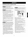 3
3
-
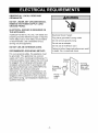 4
4
-
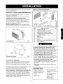 5
5
-
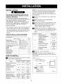 6
6
-
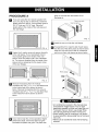 7
7
-
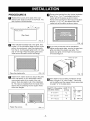 8
8
-
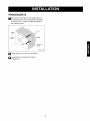 9
9
-
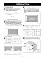 10
10
-
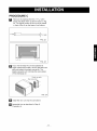 11
11
-
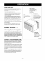 12
12
-
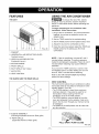 13
13
-
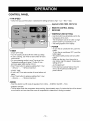 14
14
-
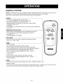 15
15
-
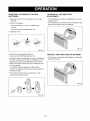 16
16
-
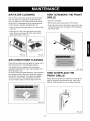 17
17
-
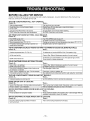 18
18
-
 19
19
-
 20
20
-
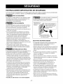 21
21
-
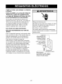 22
22
-
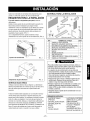 23
23
-
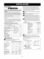 24
24
-
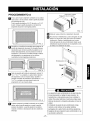 25
25
-
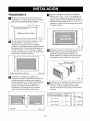 26
26
-
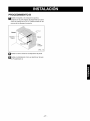 27
27
-
 28
28
-
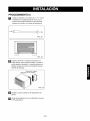 29
29
-
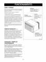 30
30
-
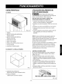 31
31
-
 32
32
-
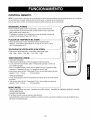 33
33
-
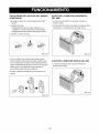 34
34
-
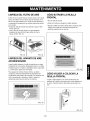 35
35
-
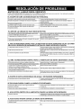 36
36
-
 37
37
-
 38
38
-
 39
39
-
 40
40


Kenmore 580.74124400 El manual del propietario
- Tipo
- El manual del propietario
- Este manual también es adecuado para
en otros idiomas
- English: Kenmore 580.74124400 Owner's manual
Artículos relacionados
-
Kenmore 580.75119500 El manual del propietario
-
Kenmore 580.72107200 El manual del propietario
-
Kenmore 580.73093300 El manual del propietario
-
-
-
-
-