Cumberland Expert WW Temperature Controller El manual del propietario
- Tipo
- El manual del propietario

GSI Electronics Inc. • 5200 Armand Frappier Saint-Hubert, Qc • Canada J3Z 1G5 • Phone: 1-877-926-2777
E-mail: [email protected]
EXPERT WW
#891-00401 REV 08
REV 19
Page 1
ADO824466
AP
Cumberland
← [13 -]
← [0-10V 2-]
← [0-10V 2 IN]
← [0-10V 1 IN]
← [0-10V 1-]
L2 (N)
L1
← [13 IN]
← [14VDC -]
← [14VDC +]
[11 -] →
[14 IN] →
[15 IN] →
[14VDC +] →
[14VDC -] →
[14VDC +] →
[11 IN] →
[POT + ] →
4
3
2
1
L1
L2
}
GND
GND
L1
L1
L2
L2
( N )
( N )
VDCCOM
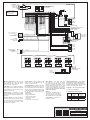
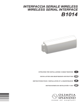
WIRING DIAGRAM EN
Please scan the QR Code to access the complete
manual or visit the website.
Cumberland: http://www.cumberlandpoultry.com
AP: http://www.automatedproduction.com
Mounting Instructions — Leave a clear-
ance of at least 16” (400 mm) to the left
of the controller box to allow the cover to
be removed for maintenance.
Cable Entry — Punch holes at the bottom of
the enclosure to allow wires to be introduced
in the controller. Do not drill the top or side
panels of the enclosure.
Alarm System — Installation of a good
quality alarm system is strongly suggested
to warn of power failures and high/low tem-
peratures.
Surge Protection — Provide a surge pro-
tection (including lightning protection) from
the power supply to the controller and from
the control to the sensors. Consult a certi-
ed electrician if required.
3-Phase Power — Same phases must be
used to power the variable fans and the
controls on 3 phases power.
Low Voltage Wires — Install low voltage ca-
bles at least 12 inches (300 mm) away from
high voltage cables (120, 230 or 380 Vac or
24 Vdc). Always use twisted shielded cables
to wire low voltage devices and always cross
high and low voltage cables at a 90° angle.
This applies to :
- Sensor cables
- Potentiometer cables
- Communication cables
- Computer link cables
- 0-10V loads
- All other low voltage devices.
Water Meter — The water meter out-
put should be a dry contact and should
not pulse faster than 60 times a second
(60Hz). A 22/12 AWG gauge cable no lon-
ger than 2000 feet (0.6 km) can be used
to connect the water meter. Do not use a
cable longer than 2000 feet even if a larger
cable is used. Do not run the meter cable
outside the building!
Relays—
Dry Contact, 15 A RES, 50/60 Hz
16 FLA @ 120 Vac (1HP, 746 W)
12 FLA @ 240 Vac (2HP, 1490 W)
Max tungsten light: 8.3A @ 120Vac.
Load Supplies — 120-240 Vac,
50-60HZ 12-24 Vdc.
Backup Thermostats — The backup
thermostats are shown for illustration
purposes only. Sucient backup ther-
mostats must be used to ensure ventila-
tion if the controller loses power.
Fuse Box — We recommend installing
a fuse box on each stage.
Potentiometer’s Color Legend
Wire
#
Commander
Actuator
VonWeise
Actuator
1 White Red
2 Red Black
3 Black White
White : not used
Green
Black
Red
Inside Probe 1
Inside Probe 2 (opt.)
Inside Probe 3 (opt.)
Inside Probe 4 (opt.)
Inside Probe 5 (opt.)
Inside Probe 6 (opt.)
Inside Probe 7 (opt.)
Outisde Probe 1 (opt.)
Inside Probe 8 (opt.)
Outisde Probe 2 (opt.)
Water meter (opt.)
Whisker switch 1 (opt.)
Whisker switch 2 (opt.)
The controller’s
power supply must
be connected to a
15A breaker!
Control
Power supply
90-240Vac
50/60Hz
30W max
EXPERT WW
0-10V
Light
output
Static pressure
sensor
Dwyer Gauge
(optional)
Outside
humidity probe
(optional)
Inside
humidity probe
(old model)
Inlet 1 potentiometer
1, 5 or 10 KOhms, 10
turns
Refer to the color
legend below
0-10V
Load 1
0-10V
Load 1
Feeder 1 (opt.)
Feeder 3 (opt.)
Feeder 2 (opt.)
Feeder 4 (opt.)
MODULE Communication
(see overleaf)
PC Communication
(see overleaf)
Alarm
Power supply
Backup thermostat
(not included)
Load 20
Power
Supply
On/O
Load
Auxiliary
output 1
Auxiliary
output 2
PC & MODULE
Communiction Ports:
see overleaf
Humidity
probe HS-1
(optional)

EXPERT WW
#891-00401 REV 08
Page 2
[MODULE 1] →
[MODULE 2] →
[PC1] →
[PC2 ] →
[14VDC-] →
COM
[MODULE 1 →]
[MODULE 2 →]
[14VDC -] →
[MODULE 2 →]
[MODULE 1 →]
[14VDC +] →
[14VDC -] →
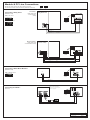
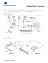
EN
WIRING DIAGRAM
Connecting the ABOX >
(PC Line)
Connecting a Water Meter Module >
(MODULE Line)
WME-8 Module ID # 3
Relay Panel CS
Relay Panel
(Non-CS model)
Comlink-1
Card
Comlink-1
Card
Comlink-1
Card
A-Com 1
Card
Black
Shield
Red
*Refer to the SureLink-2
manual to set the end of line
selectors properly.
Expert WW
Expert WW
Expert WW
Expert WW
SureLink-2 Module
WME-8 Module
Shield
Black (Com 2)
Red (Com 1)
Green
Green (GND)
Black
Red
White
Module & PC Line Connections
Set the end of line jumper to the “Yes” position on the rst
and last device of each communication line (MODULE & PC lines). No Yes
Connecting a Relay Panel
(MODULE Line)
Relés 1-16, ID n°1
ON
OFF
Relés 17-32, ID n°2
Non-CS model >
(relay panel with
4 comunication wires)
CS model >
(relay panel with
3 comunication
wires)

GSI Electronics Inc. • 5200 Armand Frappier Saint-Hubert, Qc • Canada J3Z 1G5 • Phone: 1-877-926-2777
E-mail: [email protected]
EXPERT WW
#891-00401 REV 08
REV 19
Page 1
ADO824466
AP
Cumberland
← [13 -]
← [0-10V 2-]
← [0-10V 2 IN]
← [0-10V 1 IN]
← [0-10V 1-]
L2 (N)
L1
← [13 IN]
← [14VDC -]
← [14VDC +]
[11 -] →
[14 IN] →
[15 IN] →
[14VDC +] →
[14VDC -] →
[14VDC +] →
[11 IN] →
[POT + ] →
4
3
2
1
L1
L2
}
GND
GND
L1
L1
L2
L2
( N )
( N )
VDCCOM
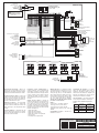
DIAGRAMA DE CABLEADO ES
Escanee el código QR para acceder al manual
completo o visite el sitio web.
Cumberland: http://www.cumberlandpoultry.com
AP: http://www.automatedproduction.com
Instrucciones de montaje — Deje un es-
pacio de por lo menos 400 mm (16“) a la iz-
quierda del controlador para poder quitar la
cubierta y darle mantenimiento a la unidad.
Conexiones de los cables — Perfore los
oricios en la parte inferior de la caja para
permitir que se introduzcan los cables en
el controlador. No perfore los paneles su-
periores ni laterales de la caja.
Sistema de alarma — Se recomienda
encarecidamente instalar un sistema de
alarma de buena calidad para advertir las
fallas de energía y las temperaturas altas
y bajas
Corriente trifásica — Se deben usar las
mismas fases para energizar los ventila-
dores de velocidad variable y los controla-
dores de corriente trifásica.
Protección contra sobretensiones —
Instale protección contra sobretensiones
temporales (incluyendo protección contra
rayos) desde la fuente de energía hasta el
control y desde el control hasta el sensor
extendido de salida. Consulte un electri-
cista certicado para las indicaciones par-
ticulares.
Cables de bajo voltaje — Separe los
cables de baja tensión al menos 300 mm
(12”) de los cables de alta tensión (120,
230 o 380 Vca o 24Vcd). Cruce siempre
los cables de baja tensión formando ángu-
los de 90º y use siempre cables trenzados
blindados para conectar los cables de baja
tensión. Esto aplica a :
- Cables de sondas
- Cables de potenciómetro
- Cables de communicación
- Cables de conexión al computador
- Cargas 0-10V.
- Otro dispositivo a baja tensión.
Medidor de agua — La salida del medidor
de agua debe ser un contacto seco y la ca-
dencia de impulsos no deberá ser mayor
de 60 por seg (60 hz). Un cable estándar
(22/12 awg) puede ser usado para conec-
tar el medición de agua. El cable no debe
ser mas largo que 600 metros (2,000 pies)
aún si un cable más largo es utilizado.
¡Nunca pase el cable de contacto solido
por fuera de la estructura!
Relés—
Contacto seco, 15 A RES, 50/60 Hz
16 FLA @ 120 Vca (1HP, 746 W)
12 FLA @ 240 Vca (2HP, 1490 W)
Tungsten máx (foco de luz): 8.3A @
120Vca
Capacidades de carga — 120-240 Vca,
50-60HZ 12-24 Vcc
Termostatos de respaldo — Los termo-
statos que aquí aparecen sólo sirven de
ilustración. Se deberá utilizar un número
suciente de termostatos de respaldo que
aseguren la ventilación en caso de que se
interrumpa la corriente al controlador.
Caja de fusibles — Se recomienda insta-
lar una caja de fusibles en cada etapa.
Colores de los cables del potenció-
metro
#
Actuador
Commander
Actuador
VonWeise
1 Blanco Rojo
2 Rojo Negro
3 Negro Blanco
Sensor Int. 1
Sensor Int. 2 (opc.)
Sensor Int. 3 (opc.)
Sensor Int. 4 (opc.)
Sensor Int. 5 (opc.)
Sensor Int. 6 (opc.)
Sensor Int. 7 (opc.)
Sensor Ext. 1 (opc.)
Sensor Int. 8 (opc.)
Sensor Ext. 2 (opc.)
Medidor de agua (opc.)
Interruptor whisker 1 (opc.)
Interruptor whisker 2 (opc.)
Alimentador 1 (opt.)
Alimentador 2 (opt.)
Alimentador 3 (opt.)
Alimentador 4 (opt.)
Blanco : no utilizado
Verde
Negro
Rojo
El suministro de
energía del controla-
dor debe encontrarse
conectado a un inter-
ruptor 15A.
Fuente de
alimentación de
control
90-240Vca
50/60Hz
30W máx
EXPERT WW
Sensor de
presión estática
Dwyer Gauge
(opcional)
Sensor
de humedad
relativa exterior
(opcional) Sensor
de humedad
relativa interior
(opcional)
Potenciómetro de la entrada
de aire 1
1, 5 o 10 KOhms,
10 espiras
(ver la inscripción de
color que gura a
continuación)
Salida de
luz 0-10V
0-10V
Carga 1
0-10V
Carga
1
Comunicación MÓDULO
(ver a la vuelta)
Comunicación PC
(ver a la vuelta)
Fuente de alimentación
de la alarma
Thermostato
de respaldo (opc.)
Fuente de
alimentación
Carga 20
Carga
On/O
Salida
auxiliar 1
Salida
auxiliar 2
Líneas de comuni-
cación MODULE y PC
ver a la vuelta
Sonda de
humedad
HS-1
(opcional)

EXPERT WW
#891-00401 REV 08
Page 2
[MODULE 1] →
[MODULE 2] →
[PC1] →
[PC2 ] →
[14VDC-] →
COM
[MODULE 1 →]
[MODULE 2 →]
[14VDC -] →
[MODULE 2 →]
[MODULE 1 →]
[14VDC +] →
[14VDC -] →
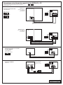
DIAGRAMA DE CABLEADO ES
Conectar la ABOX >
(Línea PC)
Conectar un módulo de medidor >
de agua (WME-8)
(Línea MODULE)
Módulo WME-8, ID # 3
Panel de relés CS
Panel de relés
(no-CS)
Tarjeta
Comlink-1
Tarjeta
Comlink-1
Tarjeta
Comlink-1
Tarjeta
A-Com 1
Black
Blindaje
Red
*Réerase al manual del
SureLink-2 para la dis-
posición adecuada del
selectador de n de linea
(EOL).
Expert WW
Expert WW
Expert WW
Expert WW
Módulo SureLink-2
Módulo WME-8
Verde
Verde
Blindaje
Negro
Negro
Rojo
Blanco
Negro
Rojo
Rojo
Conexiones a las líneas de comunicación MODULE y PC
Poner el puente de n de línea (EOL) en posición “Sí” para identicar
el primero y el último aparato de cada línea de comunicación
(Líneas MODULE y PC). No Sí
Conectar un panel de relés
(Línea MODULE)
Relés 1-16, ID n°1
ON
OFF
Relés 17-32, ID n°2
Modelo No-CS >
(panel de relés con
4 cables de
comunicación)
Modelo CS >
(panel de relés con
3 cables de
comunicación)
-
 1
1
-
 2
2
-
 3
3
-
 4
4


Cumberland Expert WW Temperature Controller El manual del propietario
- Tipo
- El manual del propietario
Documentos relacionados
Otros documentos
-
PRASTEL MT15000/EXT-IO Manual de usuario
-
 Olimpia Splendid Unico - B1014 Manual de usuario
-
Quick SBC 1450 ADV PLUS Manual de usuario
-
 Allen-Bradley 1336 IMPACT Guía de inicio rápido
-
Quick SBC 500 ADV PLUS FR Manual de usuario
-
Miller MD050233E El manual del propietario
-
-
Carel PCOXS Manual de usuario

