
I worked really hard
on this manual - so
please read it...
XOV WALL MOUNT
MODELS XOV36KSE, XOV48KSE


- 3 -
When buying any XO appliance
you can be confident you have chosen a
high quality, innovative and stylish product
from a company that cares about you!
If you require service or have questions,
there are 2 ways to contact our ventilation experts;
Online @ https://xoappliance.com/priority-service-for-your-xo-product/
Or by phone 973-403-8900
CONGRATULATIONS
on purchasing your XO.
Before you proceed, take just a
moment to register your XO at:
www.xoappliance.com/register-your-product/
REGISTRATION HELPS YOU BY -
Ensuring warranty coverage should you need service
Providing ownership verification for insurance purposes
Let’s XO notify you in the event of product changes or recalls.

- 4 -
It’s for your
own good...
Honest.
please read and follow
all safety instructions
where things are
GETTING READY
Safety and Precautions
Planning Ductwork
Install Examples
Dimensions
THE INSTALL
Mounting Height
Installing
Electrical Connections
MAINTENANCE
Filters
Cleaning
Light Replacement
PARTS & WARRANTY 20 - 21
5 - 11
12 - 14
15 - 16
OPERATING
The Controls
17 - 19

- 5 -
safety first
IMPORTANT SAFETY INSTRUCTIONS
FOR RESIDENTIAL USE ONLY
READ AND SAVE THESE INSTRUCTIONS
PLEASE READ ENTIRE INSTRUCTIONS BEFORE PROCEEDING.
IMPORTANT: Save these Instructions for the Local Electrical Inspectors use.
INSTALLER: Please leave these Instructions with this unit for the owner.
OWNER: Please retain these instructions for future reference.
Take care when using cleaning agents or detergents.
Suitable for use in household cooking area.
WARNING - To reduce the risk of fire or electric shock, do not use this fan with any
Solid-State Speed Control Device.
CAUTION - To reduce risk of fire and to properly exhaust air, be sure to duct air out-
side – Do not vent exhaust air into spaces within walls or ceilings or into attics, crawl
spaces, or garages.
CAUTION - For Residential Kitchen ventilating use only. Do not use to exhaust haz-
ardous or explosive materials and vapors.
CAUTION - To avoid motor bearing damage and noisy and/or unbalanced impellers,
keep drywall spray, construction dust, etc. off power unit.
CAUTION - Please read specification label on product for further information and
requirements.
WARNING – TO REDUCE THE RISK OF FIRE, ELECTRIC SHOCK, OR INJURY TO PERSONS,
OBSERVE THE FOLLOWING:
A. Use this unit only in the manner intended by the manufacturer. If you have questions,
contact the manufacturer.
B. Before servicing or cleaning unit, switch power off at service panel and lock the ser-
vice disconnecting means to prevent power from being switched on accidentally.
When the service disconnecting means cannot be locked, securely fasten a promi-
nent warning device, such as a tag, to the service panel.
WARNING - TO REDUCE THE RISK OF A RANGE TOP GREASE FIRE:
A. Never leave surface units unattended at high settings. Boilovers cause smoking and

- 6 -
greasy spillovers that may ignite. Heat oils slowly on low or medium settings.
B. Always turn hood ON when cooking with high heat.
C. Clean ventilating fans frequently. Grease should not be allowed to accumulate on
fan or filter.
D. Use proper pan size. Always use cookware appropriate for the size of the surface
element.
E. Keep fan, filters and grease laden surface clean.
F. Use high range setting on range only when necessary. Heat oil slowly on low to me-
dium setting.
G. Don’ t leave range unattended when cooking.
H. Always use cookware and utensils appropriate for the type and amount off food be-
ing prepared.
WARNING – TO REDUCE THE RISK OF INJURY TO PERSONS IN THE EVENT OF A RANGE
TOP GREASE FIRE, OBSERVE THE FOLLOWING:
A. SMOTHER FLAMES with a close-fitting lid, cookie sheet, or metal tray, then turn off
the burner. BE CAREFUL TO PREVENT BURNS. If the flames do not go out immediately,
EVACUATE AND CALL THE FIRE DEPARTMENT.
B. NEVER PICK UP A FLAMING PAN – You may be burned.
C. DO NOT USE WATER, including wet dishcloths or towels – a violent steam explosion
will result.
D. Use an extinguisher ONLY if:
1. You know you have a Class ABC extinguisher, and you already know how to operate it.
2. The fire is small and contained in the area where it started.
3. The fire department is being called.
4. You can fight the fire with your back to an exit.
aBased on “kitchen firesafety tips” published by NFPA.
Proper maintenance of the Range Hood will assure proper performance of the unit.
INSTALLATION INSTRUCTIONS
WARNING – TO REDUCE THE RISK OF FIRE, ELECTRIC SHOCK, OR INJURY TO PERSONS,
OBSERVE THE FOLLOWING:
A. Installation work and electrical wiring must be done by qualified person(s) in accord-
ance with all applicable codes and standards, including fire-rated construction.
B. Sufficient air is needed for proper combustion and exhausting of gases through the
flue (chimney) of fuel burning equipment to prevent back drafting. Follow the heat-
ing equipment manufacturer’s guideline and safety standards such as those pub-
lished by the National Fire Protection Association (NFPA), and the American Society
for Heating, Refrigeration and Air Conditioning Engineers (ASHRAE), and the local

- 7 -
code authorities.
C. When cutting or drilling into wall or ceiling, do not damage electrical wiring and
other hidden utilities.
D. Ducted fans must always be vented to the outdoors.
E. This unit must be grounded.
WARNING - TO REDUCE THE RISK OF FIRE, USE ONLY METAL DUCTWORK.
WARNING - UNDER CERTAIN CIRCUMSTANCES DOMESTIC APPLIANCES MAY BE
DANGEROUS.
A. Do not check filters with hood working.
B. Do not touch the lamps after a prolonged use of the appliance.
C. No food must be cooked flambè underneath the hood.
D. The use of an unprotected flame is dangerous for the filters and could cause fires.
E. Watch constantly while frying food in order to avoid cooking oil flare ups.
F. Before performing any maintenance operation, disconnect the hood from the
electrical service.
The manufacturers will not accept any responsibility for possible damages, because
of failure to observe the above instructions.

- 8 -
a few simple rules to plan your
ductwork
THIS HOOD IS DESIGNED TO USE AN 8” ROUND DUCT -
IT MAY BE TRANSITIONED TO A 4” X 14” RECTANGULAR DUCT
NEVER REDUCE DUCT SIZE. UNDERSIZED DUCTING SEVERELY RESTRICTS AIR
FLOW AND HARMS PERFORMANCE.
(Example: the area of an 8” Duct is more than 75% larger than a 6” Duct)
KEEP DUCT RUNS AS SHORT AND STRAIGHT AS POSSIBLE.
AVOID USING FLEXIBLE METAL DUCTING IF RUN IS LONGER THAN 6’.
NEVER USE PLASTIC DUCTING.
USE SMOOTH BORE METAL DUCTING.
MINIMIZE THE NUMBER OF FITTINGS (see chart).
WHEN YOU MUST USE FITTINGS, TRY TO SEPARATE THEM WITH SECTIONS OF
4’ OR MORE OF STRAIGHT DUCT.
ALWAYS FOLLOW THE MANUFACTURER’S GUIDELINES FOR THE COOKING
EQUIPMENT YOU ARE VENTING.
IF MAKE UP AIR CONTROL DAMPERS ARE REQUIRED, POSITION THE SENSOR
IN A STRAIGHT RUN OF DUCT IDEALLY WITH 4’ OF STRAIGHT DUCT BETWEEN
EACH SIDE OF THE SENSOR AND A DUCT FITTING. REMEMBER TO INCLUDE
POWER AND CONTROL WIRING FOR THIS IN YOUR PLANS.
ADHERE TO ALL LOCAL BUILDING CODES AND ORDINANCES.
USE THE WORKSHEET THAT FOLLOWS TO HELP CALCULATE THE
TOTAL EQUIVILENT FEET OF YOUR DUCT RUN.
TOTAL EQUIVILENT FEET SHOULD BE LESS THAN 100’.

- 9 -
1
1
12
7
14
8
2
4
24
24
33
CAUSING AIR TO CHANGE DIRECTION CAUSES TURBULENCE AND RESTRICTS FLOW IN
A SYSTEM.
IF USING FLEXIBLE METAL DUCT - INCREASE ALL MULTIPLIERS BY 50% (12 BECOMES
18 - ETC.)
THIS EASY TO USE WORKSHEET IS FOR 1000 CFM OR LESS.
UNDER “QTY USED” ENTER HOW OF EACH SECTION YOU WILL BE USING.
IN THE FIRST TWO ROWS - ENTER HOW MANY FEET OF EACH TYPE OF STRAIGHT DUCT
YOU WILL BE USING (I.E. FOR 20 FT ENTER 20, FOR 30FT ENTER 30).
ENTER THE NUMBER OF EACH TYPE OF TURN YOU ARE USING AND THE TYPE OF END CAP.
MULTIPLY ACROSS EACH ROW THE “MULTIPLIER” x “QTY USED” TO GET THE EQUIVALENT
FEET FOR THOSE COMPONENTS.
ADD UP ALL THE VALUES IN THE “EQUIVALENT FEET” COLUMN.
DUCT PIECE DESCRIPTION MULTIPLIER QTY USED EQUIVALENT
FEET
TOTAL EQUIVALENT FEET SHOULD BE LESS THAN 100
estimating total equivalent feet in
a duct
1’ of 8” Round Duct
1’ of 4“ x 14” Rect. Duct
8” 90 Degree Elbow
8” 45 Degree Elbow
4” x 14” 90 Degree
4” x 14” 45 Degree
4” x 14” x 8” Round
4” x 14” x 8” 90 Degree
8” Round Wall Cap w Damper
4” x 14” Wall Cap w Damper
8” Round Roof Cap

- 10 -
WALL EXHAUST ROOF EXHAUST
typical installation examples

- 11 -
11-7/32"
Max 44"
-
Aspiring Version Min. 28-3/4"
10-1/16"
27"
10-7/8"
1-9/16"
20-7/8”
5-6/8”
Ø8"
10-7/8"
1-9/16"
Front of hood Side of hood
Top of hood
dimensions
MODEL A
XOV36KSE 36”
XOV48KSE 48”
Duct cover removed

- 12 -
27”to32”
RECOMMENDED
MOUNTING HEIGHT
ABOVE GAS AND
ELECTRIC COOKTOPS
highs and lows
All range hoods have a recommended range of installation height over the cooking
surface.
It is important to install the hood at the proper mounting height. Hoods mounted too
low could result in heat damage and fire hazard; while hoods mounted too high will
be hard to reach and will lose its performance and efficiency.

- 13 -
installation
A
C
A
B
A
MOUNT TO THE WALL:
Drill the holes A respecting the distances
indicated (Fig.1). Fix the appliance to
the wall and align it in horizontal posi-
tion to the wall units. When the appli-
ance has been adjusted, definitely fix
the hood using the screws A (Fig.3). For
the various installations use screws and
screw anchors suited to the type of wall
(e.g. reinforced concrete, plasterboard,
etc.). If the screws and screw anchors are
provided with the product, check that
they are suitable for the type of wall on
which the hood is to be fixed.
INSTALL THE DUCT COVER:
Adjust the width of the support bracket of the upper flue (Fig.2). Then fix it to the ceiling
using the screws A (Fig.3) in such a way that it is in line with your hood and respecting
the distance from the ceiling indicated in Fig.1. Connect the flange C to the air exhaust
hole using a connection pipe (Fig. 3). Insert the upper flue into the lower flue. Fix the
lower flue to the hood using the screws B provided (Fig.3), extract the upper flue up to
the bracket and fix it with the screws B (Fig.2).
IMPORTANT - The range hood must be secured to wall studs or use drywall
anchors capable of supporting 75 lbs.

- 14 -
1. Route the power cord to the junction box.
2. Using listed conduit fittings and connectors,
connect the power supply to the box and each
line to the appropriate wire following this color
convention:
BLACK = HOT LEG
WHITE = NEUTRAL
GREEN/YELLOW = GROUND
Polarity must be observed.
Unit must be properly grounded.
Use a double throw disconnect switch.
3. Replace the box cover
4. Replace the Anti-grease filters.
All wiring must be in compliance with national
electrical code, ANSI/NFPA 70-1999 and all
local codes and regulations.
electrical connection

- 15 -
maintenance
Regular cleaning and maintenance is the key to long life and peak performance of any
equipment.
7KHDQWLJUHDVH¿OWHU is used to trap any grease particles suspended in the air, therefore
LVVXEMHFWWRVDWXUDWLRQWKHWLPHLWWDNHVIRUWKH¿OWHUWREHFRPHVDWXUDWHGGHSHQGVRQWKH
way in which the appliance is used). The JUHDVH¿OWHUVshould be cleaned frequently. Use a
ZDUPGHWHUJHQWVROXWLRQ*UHDVH¿OWHUVDUHDGLVKZDVKHUVDIH
7RSUHYHQWSRWHQWLDO¿UHKD]DUGVWKHDQWL
JUHDVH¿OWHUVVKRXOGEHZDVKHGDPLQLPXP
of every 2 months (it is possible to use the
dishwasher for this task).
$IWHUDIHZZDVKHVWKHFRORXURIWKH¿OWHUV
may change. This does not mean they have to
be replaced. If the replacement and washing
instructions are not followed, the anti-grease
¿OWHUVPD\SUHVHQWD¿UHKD]DUG
CLEANING STAINLESS STEEL:
Do not use corrosive detergents, abrasive detergents or oven cleaners.
Do not use any product containing chlorine bleach or any product containing chloride.
Do not use steel wool or abrasive scrubbing pads which will scratch and damage surface.
Cleaning Stainless Steel Clean periodically with warm soapy water and clean cotton cloth or
micro fiber cloth. Always rub in the direction of the stainless steel grain. To remove heavier
grease build up use a liquid degreaser detergent. After cleaning use a non-abrasive stainless
steel polish/cleaners, to polish and buff out the stainless luster and grain. Always rub lightly, with
a clean cotton cloth or a micro fiber cloth and buff in the direction of the stainless steel grain.
Any painted surfaces should be cleaned with warm water and detergent only.

- 16 -
maintenance continued
LED LIGHT REPLACEMENT
The LED light modules are held in place by
spring clips which must be squeezed in be-
fore the lamp can be pushed down through
the fascia.
Unplug the plastic molex connector.
Plug in the new fixture and snap back into
place.
XOPSPK6602

- 17 -
KEYPAD LAYOUT
DISPLAY LAYOUT
LIGHT BUTTON (1)
- Lights are three level (high, medium, low).
- From off, touch once for high.
- From off, touch twice for medium.
- From off, touch three times for low.
- From off, touch four times to cycle back to off.
- Light level will cycle from high, medium, low, off.
POWER BUTTON (2)
- Power Button will turn power on and off for the entire hood (fan and lights)
- Hood will remember the last speed and light level it was last turned off at (Example: hood
is turned off at when it was last on high speed and high lights; hood will turn back on at high
speed and high lights when Power Button is pressed)
FAN SPEED BUTTON (3)
- From off, press once for low speed (1), twice for medium (2), and three times for high (3).
- Fan should cycle through speeds low (1), medium (2), and high (3) continuously.
easy to operate

- 18 -
DELAY OFF BUTTON (4)
- If fan is off, press once and fan will turn on at low speed and automatically turn off after five
(5) minutes.
- If the fan is already on (example high speed) the fan will change to low speed when the
Delay Off Button is pressed and turn off after five minutes.
- When the Delay Off Function is on, the user can still change the fan speed by pressing the
Fan Speed Button without interrupting the five minute Delay Off Timer.
- Delay Off Function can be turned off by pressing Delay Off Function button or Power Button.
LIGHT INDICATOR (5)
- Light indicator will turn on when lights are turned on at any light level.
DELAY OFF INDICATOR (6)
- Delay Off Indicator will light up when Delay Off Function is activated by pressing the Delay
Off Button.
- Delay Off Indicator will turn off after the Delay Off Function has completed the five minute
cycle or if the user presses the Delay Off Button again or the Power Button.
delay off timer enabled and fan speed changed to 1
CLEAN AIR INDICATOR (7)
- Clean Air Indicator is disabled by default and must be enabled by the user.
7RHQDEOH&OHDQ$LU)XQFWLRQ
With hood off, hold the Power Button down for five seconds. Clean Air Indicator light will
illuminate, and the fan will turn on low speed for 10 minutes. After 10 minutes the fan will turn
off and the 4 hour timer will begin.
Clean Air Indicator will remain on when Clean Air Function is enabled, even if fan is not on.
- When Clean Air Function is enabled, every four hours of non fan usage the fan will automatically
turn on at low speed for 10 minutes. After 10 minutes the fan will turn off and the 4 hour timer
will reset.
- When the Clean Air Function automatically turns the fan on the Clean Air Indicator will blink
and the Low Speed fan indicator will illuminate.
- If the user changes the fan speed while the Clean Air Function is operating, the Clean Air
Indicator will stop blinking but will remain illuminated. When the user manually turns the hood

- 19 -
off the 4 hour timer will reset.
7RGLVDEOH&OHDQ$LU)XQFWLRQ
With hood off, hold Power Button down for five seconds until Clean Air Indicator light turns off.
Note1: Changing the fan speed and interrupting the Clean Air Function while it is operating
does not disable the Clean Air Function. Clean Air Function will only be disabled by holding
the Power Button for 5 seconds.
Note2: Turning lights on/off does not disable the Clean Air Function.
clean air function enabled with low fan speed turned on by clean air function
FAN SPEED INDICATOR (8)
= Low
= Medium
= High
- On speed low, only number 1 indicator will be on.
- On speed medium, 1 and 2 indicator will be on.
- On speed high, 1, 2 and 3 indicators will be on.
- When fan off, no fan speed indicator will be on.
REMOTE CONTROL (OPTIONAL)
Remote control (purchase separately) can be used to operate the hood.
6\QFKURQL]DWLRQ
The remote control must be synchronized with the hood before using:
To synchronize the remote control with the hood, proceed as follows:
1. Turn the power off and back on at the circuit breaker.
2. When number 5 indicator of the hood lights blinks, press any key of the remote control.
The remote control is now synchronized.
3. If synchronization failed, repeat the procedure.

- 20 -
FILTERS
REPLACEMENT LIGHTS
REMOTE CONTROLS
DUCT COVERS
REPLACEMENT SWITCHES
BLOWER MOTORS
FAN WHEELS
$//2)7+(6(3$576$1'025($5($9$,/$%/(6,03/<
9,6,7:::;2$33/,$1&(&20DQGFOLFNRQ3$5766725(
OR CALL US AT 973-403-8900
access parts & accessories

- 21 -
YEAR
WARRANTY
2
PARTS + LABOR
90 DAY LOVE IT or LEAVE IT. For 90 Days all our products are backed by our unique Love it or Leave it Guarantee.
TWO-YEAR PARTS & LABOR LIMITED WARRANTY. XO warrants to the original purchaser of every new XO ventilation
unit, the cabinet and all parts thereof, to be free from defects in material or workmanship under normal and proper use and
maintenance as specified by XO and upon proper installation and start-up in accordance with the instruction packet supplied
with each XO unit. XO’s obligation under this warranty is limited to a period of two (2) years from the date of original purchase.
WARRANTY CLAIMS. All claims for labor or parts must be made directly through XO. All claims should include: model number
and serial number of cabinet, proof of purchase, and date of installation. In case of warranted compressor, the compressor
model tag must be returned to XO along with the above listed information.
WHAT IS NOT COVERED BY THIS WARRANTY. XO’s sole obligation under this warranty is limited to either repair
or replacement of parts, subject to the additional limitations below. This warranty neither assumes nor authorizes any person
to assume obligations other than those expressly covered by this warranty. Open box, factory seconds, scratch and dent, floor
models and commercial applications are excluded from these warranties.
WARRANTY IS NOT TRANSFERABLE. This warranty is not assignable and applies only in favor of the original purchaser/
user at the original installation location. Any such assignment or transfer shall void the warranties herein made and shall void
all warranties, express or implied, including any warranty or merchantability or fitness for a particular purpose.
IMPROPER USAGE. XO assumes no liability for parts or labor coverage for component failure or other damages resulting from
improper usage or installation or failure to clean and/or maintain product as set forth in the warranty packet provided with the unit.
ALTERATION OR NEGLECT. XO is not responsible for the repair or replacement of any parts that XO determines have been
subjected after the date of manufacture to alteration, neglect, abuse, misuse, accident, damage during transit or installation,
fire, flood, or act of God.
IMPROPER ELECTRICAL CONNECTIONS. XO is not responsible for the repair or replacement of failed or damaged
components resulting from electrical power failure, high or low voltage, use of extension cords, or improper grounding of the unit.
YOUR RIGHTS UNDER STATE LAW. This warranty gives you specific legal rights and you may have other rights that
vary from state to state. Some states do not allow the exclusion or limitation of consequential damages or a limitation on how
long an implied warranty lasts, so the above exclusion or limitation may not apply to you.
OUTSIDE U.S. This warranty does not apply to, and XO is not responsible for, any warranty claims made on products sold
or used outside the 48 continental United States.
To obtain service:
Call 973-403-8900 |email ser[email protected] | or submit a request on our website
www.xoappliance.com
we’ve got your back


J’ai travaillé très
dur sur ce manuel -
veuillez donc le lire...
XOV WALL MOUNT
MODÈLES XOV36KSE, XOV48KSE

- 24 -
Lorsque vous achetez un appareil XO
vous pouvez être sûr que vous avez choisi un
produit de haute qualité, innovant et élégant
d'une entreprise qui se soucie de vous !
Si vous avez besoin d'un service ou si vous avez des
questions, il existe 2 façons de contacter nos experts en
ventilation ;
En ligne @ https://xoappliance.com/priority-service-for-your-xo-
-product/Ou par téléphone 973-403-8900
FÉLICITATIONS
pour l'achat de votre XO.
Avant de continuer, prenez un
instant pour enregistrer votre XO à
l’adresse :
www.xoappliance.com/register-your-product/
L'INSCRIPTION VOUS AIDE EN -
Assurant la couverture de garantie si vous avez besoin d'un
service. Vérifiant la propriété à des fins d'assurance XO vous
avertit en cas de changement de produit ou de rappel.

- 25 -
C’est pour
votre bien...
Honnêtement.
veuillez lire et suivre
toutes les consignes de
sécurité
où sont les choses
SE PRÉPARER
Sécurité et précautions
Planification des conduits
Exemples d’installation
Dimensions
L’INSTALLATION
Hauteur de montage
Installation
Connexions électriques
ENTRETIEN
Filtres
Nettoyage
Remplacement de la lumière
26 - 32
33 - 35
36 - 37
)21&7,211(0(17
Commandes
PIÈCES et GARANTIE
38 - 40
41 - 42

- 26 -
INSTRUCTIONS DE SECURITE IMPORTANTES
POUR UN USAGE DOMESTIQUE EXCLUSIVEMENT
LIRE ET CONSERVER LES INSTRUCTIONS
COMMENCER PAR LIRE ENTIEREMENT LES INSTRUCTIONS.
IMPORTANT: Conserver les Instructions à usage des Inspecteurs Electriques Locaux.
A L’ATTENTION DE L’INSTALLATEUR: Laisser les Instructions dans l’unité à usage du
propriétaire.
A L’ATTENTION DU PROPRIETAIRE: Conserver les Instructions pour des consultations
ultérieures.
N’utiliser des produits de nettoyage ou des détergents qu’avec la plus grande
prudence.
Cet appareil est propre à une utilisation domestique et culinaire.
AVERTISSEMENT – Afin de réduire les risques d’incendie ou d’électrocution, ne pas
utiliser le moteur avec un Dispositif de Contrôle de la Vitesse à Semi-conducteurs
quel qu’il soit.
ATTENTION – Afin de réduire les risques d’incendie et de permettre une aspiration
correcte de l’air, s’assurer que celui-ci est bien transporté à l’extérieur à travers un
conduit d’évacuation. – Ne pas évacuer l’air dans des interstices tels qu’entre des
cloisons ou des plafonds, dans des greniers, des espaces confinés ou des garages.
ATTENTION – N’utiliser que pour une ventilation générique. Cet appareil n’est pas
propre à l’aspiration de matières ou de vapeurs dangereuses ou explosives.
ATTENTION – Afin d’éviter des bruits et des dommages au niveau du moteur, et/ou
un déséquilibre au niveau des hélices, veiller à ce que l’unité d’alimentation n’entre
pas en contact avec du spray, de la poussière etc.
ATTENTION – Pour obtenir des compléments d’informations, consulter l’étiquette de
spécification sur le produit.
AVERTISSEMENT – AFIN DE RÉDUIRE LES RISQUES D’INCENDIE, D’ÉLECTROCUTION
OU DE DOMMAGES AUX PERSONNES, RESPECTER LES REGLES SUIVANTES:
A. N’utiliser l’unité que pour les opérations prévues par le fabricant. Pour toute question
éventuelle, contacter le fabricant.
B. Avant d’effectuer des opérations de maintenance ou de nettoyage sur l’unité,
débrancher le panneau de service et fermer à clef les commandes de déconnection
la sécurité d’abord

- 27 -
afin d’éviter toute mise sous tension accidentelle.
Au cas où les commandes de déconnection ne pourraient être fermées à clef, fixer sur
lepanneau de service un message avertissant du danger, par exemple une plaque.
AVERTISSEMENT – AFIN DE RÉDUIRE LES RISQUES D’INCENDIE PAR
INFLAMMATION DES GRAISSES PRESENTES SUR LA GAZINIERE:
A. Ne jamais laisser de casseroles sur feu vif sans surveillance. D’éventuels débordements
dus à une forte ébullition peuvent provoquer de la fumée et des dépôts de graisses
susceptibles de prendre feu. Réchauffer l’huile lentement, à petit feu ou moyen.
B. ALLUMER systématiquement la hotte pour cuisiner à des températures élevées.
C. Nettoyer souvent le moteur. Eviter que les graisses ne s’accumulent sur le moteur ou
sur le filtre.
D. Utiliser des plats aux dimensions adaptées. Toujours utiliser des ustensiles de cuisine
adaptés à la taille de la casserole qui se trouve sur la cuisinière.
E. Veiller à ce que le moteur, les filtres et la surface où viennent s’accumuler les graisses
restent propres.
F. N’utiliser une flamme élevée que lorsque cela est nécessaire. Réchauffer l’huile
lentement, à faible ou moyenne température.
G. Ne jamais laisser la cuisinière sans surveillance pendant la cuisson.
H. Utiliser systématiquement des ustensiles de cuisine adaptés au type et à la quantité
d’aliments que l’on prépare.
AVERTISSEMENT – AFIN DE RÉDUIRE LES RISQUES DE DOMMAGES AUX PERSONNES
EN CAS D’INCENDIE PAR INFLAMMATION DES GRAISSES PRESENTES SUR LA
CUISINIERE, RESPECTER LES REGLES SUIVANTESa:
A. ETOUFFER LA FLAMME à l’aide d’un couvercle hermétique, une plaque à four ou un
plateau en métal et éteindre le brûleur. PROCEDER AVEC LA PLUS GRANDE PRUDENCE
AFIN D’EVITER TOUTE BRULURE. Si les flammes ne s’éteignent pas immédiatement,
EVACUER LA PIECE ET APPELER LES POMPIERS.
B. NE JAMAIS TOUCHER UN PLAT EN FEU – on risque de se brûler.
C. NE PAS UTILISER D’EAU, ni de chiffons ou de serviettes humides – cela pourrait
provoquer une violente explosion de vapeur.
D. Utiliser un extincteur UNIQUEMENT dans les cas suivants:
1. On dispose d’un extincteur de Classe ABC que l’on sait faire fonctionner.
2. L’incendie est peu important et il est confiné à la zone où il a éclaté.
3. On a déjà appelé les pompiers.
4. On peut affronter les flammes tout en ayant une issue de secours derrière soi.
aBasé sur les « mesures de sécurité incendie dans la cuisine « publiées par l’organisme
NFPA.
Une bonne maintenance de la hotte garantit le parfait fonctionnement de l’unité.

- 28 -
INSTRUCTIONS D’INSTALLATION
AVERTISSEMENT – AFIN DE RÉDUIRE LES RISQUES D’INCENDIE, D’ÉLECTROCUTION
OU DE DOMMAGES AUX PERSONNES, RESPECTER LES REGLES SUIVANTES:
A. Les opérations d’installation et de branchement électrique doivent être effectuées
par du personnel qualifié, conformément aux lois et aux normes en vigueur, y compris
celles relatives aux appareils à feu.
B. Il est nécessaire de disposer d’une quantité d’air suffisante pour une bonne
combustion et aspiration des gaz à travers le conduit de fumée de l’installation de
combustion du carburant, afin d’éviter un appel d’air de l’arrière. Suivre les indications
du fabricant de l’installation de chauffage et les normes de sécurité correspondantes
telles que celles émises par l’Association Nationale de Protection contre les Incendies
(National Fire Protection Association - NFPA), la Société Américaine des Techniciens
de Chauffage, Réfrigération et Climatisation de l’Air (American Society for Heating,
Refrigeration and Air Conditioning Engineers - ASHRAE), et par les autorités locales
préposées.
C. Au cours des opérations de découpage ou de perforation du mur ou du plafond,
veiller à ne pas endommager les câbles électriques ou d’autres canalisations cachées.
D. L’appareil doit toujours être relié à un trou d’évacuation vers l’extérieur.
E. L’unité doit être reliée à la terre.
AVERTISSEMENT – AFIN DE RÉDUIRE LES RISQUES D’INCENDIE, N’UTILISER QUE
DESCONDUITS METALLIQUES
AVERTISSEMENT – LES APPAREILS ELECTROMENAGERS PEUVENT PARFOIS S’AVERER
DANGEREUX.
A. Ne pas contrôler les filtres lorsque la hotte est en état de marche.
B. Ne pas toucher les lampes après une utilisation prolongée de l’appareil.
C. Ne jamais faire flamber d’aliments sous la hotte.
D. L’usage de flammes libres est dangereux pour les filtres et peut générer des incendies.
E. Contrôler constamment les fritures pour éviter que des éclaboussures d’huile ne
prennent feu.
F. Avant d’effectuer toute opération de maintenance, débrancher la hotte du réseau
d’alimentation électrique.
Le fabricant ne pourra être retenu responsable d’éventuels dommages causés par le
non respect des instructions susmentionnées.

- 29 -
quelques règles simples pour pla-
nifier votre canalisation
CETTE HOTTE EST CONÇUE POUR UTILISER UN CONDUIT ROND DE 8 PO -
IL PEUT ÊTRE TRANSITIONNÉ EN UN CONDUIT RECTANGULAIRE 4 po X 14 po
NE JAMAIS RÉDUIRE LA TAILLE DU CONDUIT. LES CONDUITS SOUS-DIMENSIO-
NNÉS RESTREIGNENT CONSIDÉRABLEMENT LE DÉBIT D'AIR ET NUISENT AUX
PERFORMANCES.
(Exemple : la surface d'un conduit de 8 po est plus de 75% plus grande qu’un con-
duit de 6 po)
GARDER LES CONDUITES AUSSI COURTES ET DROITES QUE POSSIBLE.
ÉVITEZ D'UTILISER DES CONDUITS MÉTALLIQUES FLEXIBLES SI LA LONGUEUR
EST SUPÉRIEURE À 6 pi.
N'UTILISEZ JAMAIS DE CONDUITS EN PLASTIQUE.
UTILISER UN CONDUIT MÉTALLIQUE À ALÉSAGE LISSE.
MINIMISER LE NOMBRE DE RACCORDS (voir tableau).
LORSQUE VOUS DEVEZ UTILISER DES RACCORDS, ESSAYEZ DE LES SÉPARER
AVEC DES SECTIONS DE 4 pi OU PLUS DE CONDUIT DROIT.
SUIVEZ TOUJOURS LES DIRECTIVES DU FABRICANT POUR L'ÉQUIPEMENT DE
CUISSON QUE VOUS VENTILEZ.
SI DES AMORTISSEURS DE COMMANDE D'AIR SONT NÉCESSAIRES, POSITIONNEZ
LE CAPTEUR DANS UN CONDUIT EN LIGNE DROITE IDÉALEMENT AVEC UN CON-
DUIT EN LIGNE DROITE DE 4 pi ENTRE CHAQUE CÔTÉ DU CAPTEUR ET UN RAC-
CORD DE CONDUIT. N'OUBLIEZ PAS D'INCLURE LE CÂBLAGE D'ALIMENTATION
ET DE COMMANDE DANS VOS PLANS.
RESPECTEZ TOUS LES CODES ET DÉCRETS LOCAUX DU BÂTIMENT.
UTILISEZ LA FEUILLE DE TRAVAIL QUI SUIT POUR VOUS AIDER À CALCULER LE
TOTAL DES PIEDS ÉQUIVALENTS DE VOTRE CONDUIT.
LE TOTAL DES PIEDS ÉQUIVALENTS DOIT ÊTRE INFÉRIEUR À 100 pi.

- 30 -
1
1
12
7
14
8
2
4
24
24
33
LE FAIT DE PROVOQUER UN CHANGEMENT DE DIRECTION DE L'AIR PROVOQUE DES
TURBULENCES ET RESTREINT LE DÉBIT DANS UN SYSTÈME.
SI VOUS UTILISEZ UN CONDUIT MÉTALLIQUE FLEXIBLE - AUGMENTEZ TOUS LES MULTI-
PLICATEURS DE 50 % (12 DEVIENT 18 - ETC.)
CETTE FEUILLE DE CALCUL FACILE À UTILISER EST POUR 1000 CFM OU MOINS.
SOUS « QTÉ UTILISÉE », ENTREZ LE MODE D'UTILISATION DE CHAQUE SECTION.
DANS LES DEUX PREMIÈRES LIGNES - ENTREZ LE NOMBRE DE PIEDS DE CHAQUE TYPE
DE CONDUIT DROIT QUE VOUS UTILISEREZ (C.-À-D. POUR 20 PI, ENTREZ 20, POUR 30
PI, ENTREZ 30).
SAISISSEZ LE NOMBRE DE CHAQUE TYPE DE COURBE QUE VOUS UTILISEZ ET LE TYPE
DE CAPUCHON D'EXTRÉMITÉ OF.
MULTIPLIEZ SUR CHAQUE LIGNE LE « MULTIPLICATEUR » X « QUANTITÉ UTILISÉE » POUR
OBTENIR LES PIEDS ÉQUIVALENTS POUR CES COMPOSANTS.
AJOUTEZ TOUTES LES VALEURS DANS LA COLONNE « PIEDS ÉQUIVALENTS ».
PIÈCE DE
CONDUIT
DESCRIPTION MULTIPLICA-
TEUR
QTÉ
UTILISÉE
PIEDS
ÉQUIVALENTS
LE TOTAL DES PIEDS ÉQUIVALENTS DOIT ÊTRE INFÉRIEUR À 100
estimation des pieds équivalents
totaux dans un conduit
Conduit rond de 1 pi sur 8 po
1 pi de conduit rectangulaire
4 po x 14 po
Coude de 8 po à 90 degrés
Coude de 8 po à 45 degrés
4 po x 14 po à 90 degrés
4 po x 14 po à 45 degrés
Rond 4 po x 14 po x 8 po
4 po x 14 po x 8 po à 90
degrés
Capuchon de toit rond de
8 po
Capuchon mural rond de 8
po avec amortisseur
Capuchon mural de 4 po x 14
po avec amortisseur

- 31 -
ÉVENT D’ÉCHAPPEMENT
MURAL ÉVENT D’ÉCHAPPEMENT
DE TOIT
exemples d'installation typiques

- 32 -
11-7/32"
Max 44"
-
Aspiring Version Min. 28-3/4"
10-1/16"
27"
10-7/8"
1-9/16"
20-7/8”
5-6/8”
Ø8"
10-7/8"
1-9/16"
Devant de la hotte Côté de la hotte
Haut de la hotte
dimensions
MODÈLE A
XOV36KSE 36”
XOV48KSE 48” Couverture de conduit retiré

- 33 -
27”to32”
HAUTEUR DE MONTA-
GE RECOMMANDÉE
AU-DESSUS DES PLA-
QUES DE CUISSON AU
GAZ ET ÉLECTRIQUES
hauts et bas
Toutes les hottes de cuisinière ont une plage de hauteur d'installation recommandée
sur la surface de cuisson.
Il est important d'installer la hotte à la bonne hauteur de montage. Les hottes mon-
tées trop bas peuvent entraîner des dommages causés par la chaleur et un risque
d'incendie ; tandis que les hottes montées trop haut seront difficiles à atteindre et
perdront leurs performances et leur efficacité.

- 34 -
installation
A
C
A
B
A
MONTAGE AU MUR:
A l’aide d’une perceuse, effectuer les
trous A en respectant les distances indi-
quées sur la figure 1. Fixer l’appareil à la
paroi et l’aligner en position horizontale
avec les unités déjà fixées sur le mur. Une
fois l’appareil réglé, le fixer définitive-
ment à l’aide des vis A (Fig.3). Pour les
différentes installations utiliser les vis et
les supports correspondants adaptés au
type de mur sur lequel on entend fixer
l’appareil (béton armé, placopatre etc.).
Dans le cas où les vis et les supports
correspondants fournis avec le produit,
contrôler qu’ils sont bien adaptés au
type de mur sur lequel sera fixé la hotte.
INSTALLATION DE LA COUVERTURE DU TUYAU:
Régler la largeur de l’étrier de support du tube décoratif supérieur (Fig.2). Fixer l’étrier au
plafond au moyen des vis A (Fig.2) de façon à les aligner avec la hotte et en respectant la
distance par rapport au plafond comme indiqué sur la figure 1. Relier la bride C au trou
d’évacuation d’air en utilisant un tube de raccordement (Fig.3). Insérer le tube décoratif
supérieur à l’intérieur du tube inférieur. Fixer ce dernier à la hotte au moyen des vis B
fournies (Fig.3), extraire le tube supérieur en le portant à hauteur de l’étrier et le fixer à
l’aide des vis B (Fig.2).
IMPORTANT: La hotte doit être fixée au mur avec des pivots de support
filetés ou des chevilles d’une capacité de 75 livres.

- 35 -
1. Acheminez le cordon d'alimentation vers la
boîte de jonction.
2. À l'aide des raccords et connecteurs de
conduit répertoriés, connectez l'alimentation
à la boîte et chaque ligne au fil approprié en
suivant cette convention de couleur :
NOIR = PIED CHAUD
BLANC = NEUTRE
VERT/JAUNE = SOL
La polarité doit être observée.
L'unité doit être correctement mise à la terre.
Utilisez un interrupteur de déconnexion à
double jet.
3. Remplacez le couvercle de la boîte
4. Remplacez les filtres anti-graisse.
Tout le câblage doit être conforme au code
électrique national, ANSI/NFPA 70-1999 et à
tous les codes et réglementations locaux.
connexion électrique

- 36 -
maintenance
NETTOYAGE DE L’ACIER INOXYDABLE :
N'utilisez pas de détergents corrosifs, de détergents abrasifs ou de nettoyants pour fours.
N'utilisez aucun produit contenant de l'eau de Javel chlorée ou un produit contenant du
chlorure.
N'utilisez pas de laine d'acier ou de tampons abrasifs qui risquent de rayer et d'endommager
la surface.
Nettoyage de l'acier inoxydable Nettoyez régulièrement avec de l'eau chaude savonneuse
et un chiffon en coton propre ou un chiffon en microfibres. Frottez toujours dans le sens du
grain de l'acier inoxydable. Pour éliminer l'accumulation de graisse plus lourde, utilisez un
détergent dégraissant liquide. Après le nettoyage, utilisez un produit de polissage/nettoyant
pour acier inoxydable non abrasif pour polir et polir le lustre et le grain de l'acier inoxydable.
Frottez toujours légèrement avec un chiffon en coton propre ou un chiffon en microfibres et
polissez dans le sens du grain de l'acier inoxydable.
Toutes les surfaces peintes doivent être nettoyées avec de l'eau chaude et du détergent
uniquement.
Le nettoyage et la maintenance réguliers sont la clé d’une longue durée de vie et des per-
formances de pointe de tout équipement.
/H¿OWUHDQWLJUDLVVHa pour rôle de retenir les particules grasses en suspension dans l’air.
Il peut donc se boucher plus ou moins rapidement selon la fréquence d’utilisation de la hotte.
1HWWR\HUIUpTXHPPHQWOHV¿OWUHVGHODJUDLVVHjO¶DLGHG¶XQHVROXWLRQGpWHUJHQWH
/HV¿OWUHV GHOD JUDLVVHSHXYHQW rWUHODYpV
dans le lave-vaisselle.
- Pour prévenir tout risque d’incendie, il faut
ODYHUOHV¿OWUHVDQWLJUDLVVHDXPRLQVWRXVOHV
2 mois, ces derniers son lavables même au
lave-vaisselle.
- Après plusieurs lavages, ils peuvent
changer de couleur. Ceci ne donne pas droit
à réclamation ni droit, par conséquent, à leur
remplacement.
Le non-respect des consignes de remplace-
ment et de lavage peut entraîner un risque
G¶LQFHQGLHGHV¿OWUHVDQWLJUDLVVH
.

- 37 -
suite de la maintenance
REMPLACEMENT DE LA LUMIÈRE LED
Les modules d’éclairage LED sont maintenus
en place par des pinces à ressort qui doivent
être enfoncées avant que la lampe puisse être
poussée vers le bas à travers la façade.
Débranchez le connecteur molex en plastique.
Branchez le nouveau luminaire et remettez-le
en place.
XOPSPK6602

- 38 -
facile à utiliser
CONFIGURATION DES COMMANDES
CONFIGURATION DE L’ÉCRAN
TOUCHE LIGHT (LUMIÈRES) (1)
- Trois niveaux de lumières sont prévus : haut, moyen, bas.
- À partir de la position Éteint, appuyez une fois pour le niveau haut.
- À partir de la position Éteint, appuyez deux fois pour le niveau moyen.
- À partir de la position Éteint, appuyez trois fois pour le niveau bas.
- À partir de la position Éteint, appuyez quatre fois pour ramener le cycle à sa position de
départ.
- Le niveau des lumières a une évolution cyclique et passe du niveau haut, au niveau moyen,
au niveau bas, jusqu’à la position Éteint.
TOUCHE POWER (ALLUMAGE / EXTINCTION) (2)
- La touche d’allumage / extinction sert à mettre en marche et à arrêter la hotte en entier
(turbine et lumières).
- La hotte garde en mémoire le dernier réglage de la vitesse et des lumières qui était présent
au moment où l’appareil est arrêté (par exemple : si la hotte est arrêtée avec la vitesse et
les lumières réglées au maximum, quand elle remise en marche en appuyant sur la touche
d’allumage/extinction, la vitesse et les turbines sont encore réglées au niveau maximum).
TOUCHE FAN SPEED (VITESSE TURBINE) (3)
- À partir de la position OFF (Éteint), appuyez une fois pour régler la petite vitesse (1), deux
fois pour la vitesse moyenne (2) et trois fois pour la grande vitesse (3).

- 39 -
- La vitesse de la turbine a une évolution cyclique et passe continuellement de la petite (1),
à la moyenne (2) à la grande vitesse (3).
TOUCHE DELAY OFF (EXTINCTION DIFFÉRÉE) (4)
- Si la turbine est à l’arrêt, en appuyant une fois sur la touche, elle se met en marche à petite
vitesse et s’arrête automatiquement au bout de cinq (5) minutes.
- Si la turbine est déjà en marche (par exemple à grande vitesse), elle passe à la petite vitesse
quand on appuie sur la touche d’extinction différée, et s’arrête au bout de cinq minutes.
- Quand la fonction d’extinction différée est activée, l’utilisateur peut encore modifier la vitesse
de la turbine en appuyant sur la touche Vitesse turbine sans pour autant interrompre les cinq
minutes réglées pour l’extinction différée.
- La fonction d’extinction différée peut être désactivée en appuyant sur la touche d’extinction
différée ou sur la touche d’allumage/extinction.
VOYANT LUMIÈRES (5)
- Le voyant lumières s’allume quand les lumières sont allumées à n’importe quel niveau.
VOYANT D’EXTINCTION DIFFÉRÉE (6)
- Le voyant d’extinction différée s’allume quand la fonction d’extinction différée est activée
en appuyant sur la touche correspondante.
- Le voyant d’extinction différée s’allume après que la fonction d’extinction différée a
complété son cycle de cinq minutes ou bien quand l’utilisateur appuie à nouveau sur la
touche d’extinction différée ou sur la touche d’allumage/extinction.
voyant de delai d’extinction illuminé à la velocité 1
VOYANT D’AIR PROPRE (FONCTION AIR PROPRE) (7)
- Le voyant d’air propre n’est pas activé par défaut. C’est donc l’utilisateur qui doit activer cette
fonction.
3RXUDFWLYHUODIRQFWLRQG¶DLUSURSUH
Avec la hotte à l’arrêt, maintenez la touche d’allumage/extinction enfoncée pendant cinq
secondes. Le voyant d’air propre s’allume et la turbine se met en marche à petite vitesse
pendant 10 minutes. Au bout de 10 minutes, la turbine s’arrête et le réglage de 4 heures
s’active.
Le voyant d’air propre reste allumé au fixe quand la fonction d’air propre est activée, même
si la turbine est à l’arrêt.
- Quand la fonction d’air propre est activée la turbine étant à l’arrêt, cette dernière se met en
marche automatiquement toutes les quatre heures à petite vitesse pendant 10 minutes. Au

- 40 -
bout de 10 minutes, la turbine s’arrête et le réglage de 4 heures s’active.
- Quand la fonction d’air propre met en marche automatiquement la turbine, le voyant d’air
propre commence à clignoter et le voyant de la turbine à petite vitesse s’allume.
- Si l’utilisateur modifie la vitesse de la turbine pendant que la fonction d’air propre est activée,
la lumière du voyant d’air propre cesse de clignoter et reste allumée au fixe. Quant l’utilisateur
arrête manuellement la hotte, le réglage de 4 heures repart de zéro.
3RXUGpVDFWLYHUODIRQFWLRQG¶DLUSURSUH
Avec la hotte à l’arrêt, maintenez la touche d’allumage/extinction enfoncée pendant cinq
secondes, jusqu’à ce que le voyant d’air propre s’éteigne.
Note1: La fonction d’air propre n’est pas désactivée même si la vitesse de la turbine est
modifiée et que la fonction d’air propre est interrompue pendant le fonctionnement. La fonction
d’air propre n’est désactivée qu’en maintenant la touche d’allumage/extinction appuyée
pendant 5 secondes.
Note2: La fonction d’air propre reste activée même si les lumières sont allumées/éteintes.
voyant clignotant function air nettoyée ò la velocité plus bas.
VOYANT VITESSE TURBINE (8)
= Petite vitesse
= Vitesse moyenne
= Grande vitesse
- Petite vitesse: seulement le voyant 1 est allumé.
- Vitesse moyenne: les voyants 1 et 2 sont allumés.
- Grande vitesse: les voyants 1, 2 et 3 sont allumés.
- Quand la turbine est à l’arrêt, tous les voyants de vitesse de la turbine sont éteints.
TÉLÉCOMMANDE (OPTIONNEL)
Le Télécommande (à acheter séparément) peut être utilisé pour faire fonctionner la hotte.
6\QFKURQLVDWLRQ
Avant l’utilisation, la télécommande doit être synchronisée avec la hotte.
Pour ce faire, suivez la procédure ci-après :
1. Débranchez la hotte du secteur et rebranchez-le.
2. Lorsque le voyant 5 de la hotte clignote, appuyez sur une touche quelconque de la
télécommande. Cette dernière est alors synchronisée.
3. Si la synchronisation ne réussit pas, répétez la procédure

- 41 -
FILTRES
LUMIÈRES DE REMPLACEMENT
TÉLÉCOMMANDES
COUVERCLES DE CONDUITS
INTERRUPTEURS DE REMPLACEMENT
MOTEURS DE VENTILATEUR
ROUES DE VENTILATEUR
7287(6&(63,Ê&(6(73/866217',6321,%/(69,6,7(=
6,03/(0(17::;2$33/,$1&(&20HWFOLTXH]VXU/(
MAGASIN DE PIÈCES OU APPELEZ-NOUS AU 973-403-8900
accessoires et pièces d'accès

- 42 -
YEAR
WARRANTY
2
PARTS + LABOR
GARANTIE DE REMBOURSEMENT 90 JOURS. Pendant 90 jours, tous nos produits sont soutenus par notre garantie unique
Love it or Leave it.
GARANTIE LIMITÉE DE DEUX ANS SUR LES PIÈCES et LA MAIN-D' ŒUVRE. XO garantit à l'acheteur initial de chaque
nouvelle unité de ventilation XO, de l'armoire et de toutes les parties de celle-ci, d'être exempt de défauts de matériau ou de
fabrication dans le cadre d'une utilisation et d'un entretien normaux et appropriés comme spécifié par XO et lors d'une installation
et d'un démarrage appropriés conformément au paquet d'instructions fourni avec chaque unité XO. L'obligation de XO en vertu
de cette garantie est limitée à une période de deux (2) ans à compter de la date d'achat initiale.
RÉCLAMATIONS DE GARANTIE. Toutes les demandes de main-d' œuvre ou de pièces doivent être faites directement par
l'intermédiaire de XO. Toutes les réclamations doivent inclure : le numéro de modèle et le numéro de série de l'armoire, la
preuve d'achat et la date d'installation. Dans le cas d'un compresseur garanti, l'étiquette du modèle de compresseur doit être
retournée à XO avec les informations énumérées ci-dessus.
CE QUI N'EST PAS COUVERT PAR CETTE GARANTIE. La seule obligation de XO en vertu de cette garantie est
limitée à la réparation ou au remplacement des pièces, sous réserve des limitations supplémentaires ci-dessous. Cette garantie
n'assume ni n'autorise quiconque à assumer des obligations autres que celles expressément couvertes par la présente garantie.
Les boîtes ouvertes, les défauts d'usine, les rayures et bosselures, les modèles de plancher et les applications commerciales
sont exclus de ces garanties.
LA GARANTIE N'EST PAS TRANSFÉRABLE. Cette garantie n'est pas cessible et ne s'applique qu'en faveur de l'acheteur/
utilisateur d'origine sur le site d'installation d'origine. Une telle cession ou un tel transfert annulera les garanties faites dans
les présentes et annulera toutes les garanties, expresses ou implicites, y compris toute garantie ou qualité marchande ou
adéquation à un usage particulier.
MAUVAISE UTILISATION. XO n'assume aucune responsabilité pour les pièces ou la main-d' œuvre en cas de défaillance
des composants ou d'autres dommages résultant d'une utilisation ou d'une installation incorrecte ou d'un défaut de nettoyage
et/ou d'entretien du produit comme indiqué dans le paquet de garantie fourni avec l'unité.
MODIFICATION OU NÉGLIGENCE. XO n'est pas responsable de la réparation ou du remplacement des pièces qui, selon XO,
ont été soumises après la date de fabrication à une altération, une négligence, un abus, une mauvaise utilisation, un accident,
des dommages pendant le transport ou l'installation, un incendie, une inondation ou un cas de force majeure.
MAUVAISES CONNEXIONS ÉLECTRIQUES. XO n'est pas responsable de la réparation ou du remplacement des
composants défectueux ou endommagés résultant d'une panne d'alimentation électrique, d'une tension élevée ou basse, de
l'utilisation de rallonges ou d'une mise à la terre incorrecte de l'appareil.
VOS DROITS EN VERTU DE LA LOI DE L'ÉTAT. Cette garantie vous donne des droits légaux spécifiques et
vous pouvez avoir d'autres droits qui varient d'un État à l'autre. Certains États n'autorisent pas l'exclusion ou la limitation des
dommages indirects ou une limitation de la durée d'une garantie implicite, de sorte que l'exclusion ou la limitation ci-dessus
peut ne pas s'appliquer à vous.
EN dehors des États-Unis Cette garantie ne s'applique pas et XO n'est pas responsable des réclamations de garantie
faites sur les produits vendus ou utilisés en dehors des 48 États-Unis continentaux.
Pour obtenir de l’entretien :
Appelez le 973-403-8900 |envoyez un courriel à ser[email protected] | ou envoyez
une demande sur notre site Web www.xoappliance.com
on couvre vos arrières

He trabajado mucho
en este manual - así
que léalo...
XOV WALL MOUNT
MODELOS XOV36KSE, XOV48KSE

- 44 -
Al comprar cualquier aparato XO
puede estar seguro de que ha elegido un
producto de alta calidad, innovador y elegante
de una empresa que se ¡preocupa por ti!
Si necesita servicio o tiene preguntas, hay 2 maneras de
comunicarse con nuestros expertos en ventilación;
En línea @ https://xoappliance.com/priority-service-for-your-xo-
-product/Or por teléfono 973-403-8900
ENHORABUENA
por la compra de su XO.
Antes de continuar, tómese un
momento para registrar su XO en:
www.xoappliance.com/register-your-product/
EL REGISTRO LE AYUDA PARA -
Garantizar la cobertura de la garantía en caso de que ne-
cesite servicio. Suministrar la verificación de la propiedad
para fines de seguros. Permita que XO le notifique en caso de
cambios o retiros de productos.

- 45 -
Es por su
propio bien...
Honesto.
por favor lea y siga todas
las instrucciones de seguridad
donde están las cosas
PREPARÁNDOSE
Seguridad y Precauciones
Planificación de Ductos
Ejemplos de instalación
Dimensiones
LA INSTALACIÓN
Altura de Montaje
Instalación
Conexiones eléctricas
MANTENIMIENTO
Filtros
Limpieza
Sustitución de la Luz
46 - 52
53 - 55
56 - 57
)81&,21$0,(172
Controles
PIEZAS y GARANTÍA
58 - 60
61 - 62

- 46 -
seguridad primero
INSTRUCCIONES IMPORTANTES DE SEGURIDAD
RELATIVAS SOLO AL USO DOMESTICO
LEA LAS INSTRUCCIONES COMPLETAMENTE ANTES DE PROCEDER.
IMPORTANTE: Guarde las Instrucciones de uso de los Inspectores Eléctricos Locales.
PARA EL INSTALADOR: Deje las Instrucciones en la unidad de uso del proprietario.
PARA EL PROPIETARIO: Guarde las instrucciones para consultas futuras.
Preste máxima atención durante el uso de productos de limpieza o detergentes.
Aparato adapto para uso doméstico y culinario.
ADVERTENCIA – Para reducir el riesgo de incendio o de sacudida eléctrica, no use el
motor junto con ningún Dispositivo de Control de Velocidad con Semiconductores.
ATENCION – Para reducir el riesgo de incendio y aspirar correctamente el aire,
asegúrese que esta última sea transportada al externo a través de un conducto de
evacuación. – No descargue el aire en paredes dobles entre paredes o techos o en
desvanes, espacios angostos o garajes.
ATENCION – Usar sólo para una ventilación general. No es adapto para aspirar
materiales o vapores peligrosos o explosivos.
ATENCION – Para evitar daños al motor y rumores, y/o hélices desbalanceadas, evite
que la unidad de alimentación llegue a contacto con esprays, polvo, etc.
ATENCION – Para ulterior información y pedidos, lea la etiqueta de especificación del
producto.
ADVERTENCIA – PARA REDUCIR EL RIESGO DE INCENDIO, SACUDIDA ELECTRICA O
SDAÑOS A PERSONAS, SIGA LAS SIGUIENTES PAUTAS:
A. Use la unidad sólo para finalidades previstas por el fabricante. Para eventuales
preguntas, contacte el fabricante.
B. Antes de efectuar operaciones de mantención o limpieza a la unidad, desconecte la
corriente del panel de servicio y cierre con llave los comandos de desconexión para
evitar que se encienda accidentalmente la corriente de alimentación.
Si los comandos de desconexión no pueden ser cerrados con llave, fije firmemente
un aviso de peligro que sea evidente al panel de servicio, como una placa por ejemplo.
ADVERTENCIA – PARA REDUCIR EL RIESGO QUE LA GRASA DE LA SUPERFICIE
DEL HORNO SE INCENDIE:
A. Nunca deje ollas en la superficie del horno en posición alta sin supervisión. Eventua
les desbordamientos por el hervor pueden causar humo y rebalses de grasa que pue

- 47 -
den encenderse. Caliente el aceite lentamente en posición baja o media.
B. ENCIENDA siempre la campana cuando cocine a temperaturas elevadas.
C. Encienda frecuentemente el motor. Evite que la grasa se acumule en el motor o en el
filtro.
D. Use cazuelas de dimensiones adaptas. Siempre utilize utensilios de cocina idóneos a
la dimensión de la olla que se encuentra sobre la superficie del horno.
E. Mantenga limpio el motor, los filtros y la superficie donde se acumula la grasa.
F. Use el horno en posición alta sólo cuando sea necesario. Caliente el aceite lentamen-
te en posición baja o media.
G. No deje nunca el horno sin supervisión durante la cocción.
H. Use siempre utensilios y herramientas de cocina adaptos al tipo y a la cantidad de
comida que esté preparando.
ADVERTENCIA – PARA REDUCIR EL RIESGO DE DAÑOS A PERSONAS EN CASO QUE SE
ENCIENDA LA GRASA DE LA SUPERFICIE DEL HORNO, SIGA LAS SIGUIENTES PAUTASa:
A. SOFOQUE LAS LLAMAS con una tapa hermética, una losa de horno o una bandeja
metálica y luego apague el quemador. PRESTE MUCHA ATENCION DURANTE
ESTA OPERACION PARA EVITAR QUEMADURAS. Si las llamas no se extinguen
inmediatamente, EVACUE EL LUGAR Y LLAME A LOS BOMBEROS.
B. NO TOQUE NUNCA UNA CAZUELA HIRVIENTE – se puede quemar.
C. NO USE AGUA, inclusive estropajos o toallas húmedas – se produciría una violenta
explosión de vapor.
D. Use un extinguidor SOLO en caso que:
1. Se tenga un extinguidor de Clase ABC y sepa utilizarlo.
2. Sea un incendio de dimensiones pequeñas y contenido en el área en la cual ha
estallado.
3. Ya hayan sido llamados los bomberos.
4. Se puedan afrontar las llamas con la espalda dirigida hacia una salida.
aBasado en las “medidas sobre seguridad antiincendio en la cocina” publicadas por el
NFPA.
Una correcta mantención de la campana garantiza un funcionamiento perfecto de
la unidad.
INSTRUCCIONES PARA LA INSTALACION
ADVERTENCIA – PARA REDUCIR EL RIESGO DE INCENDIO, SACUDIDA ELECTRICA O
DAÑOS A PERSONAS, SIGA LAS SIGUIENTES PAUTAS:
A. Las operaciones de instalación y conexión eléctrica deben ser efectuadas por
personal calificado, conforme con las leyes y normativas en vigor, incluyendo las de
aparatos de fuego.
B. Es necesario tener una cantidad de aire suficiente para obtener una combustión

- 48 -
y aspiración del gas correcta a través del humero de la planta de combustión del
carburante, para evitar un tiro del del aire en la parte posterior. Sega las indicaciones
del fabricante de la planta de calefacción y las relativas normas de seguridad, como
las emitidas por la Asociación Nacional de Protección contra Incendios (National Fire
Protection Association - NFPA), por la Sociedad Americana de Técnicos de Calefacción,
Refrigeración y Aire Acondicionado (American Society for Heating, Refrigeration and
Air Conditioning Engineers - ASHRAE) y por las autoridades de códigos locales.
C. Cuando corte o taladre en la pared o el techo, no dañe el cableado eléctrico ni otras
utilidades escondidas.
D. El aparato debe estar siempre conectado a un agujero de evacuación hacia el exterior.
E. La unidad deber ser conectada al suelo.
ADVERTENCIA – PARA REDUCIR EL RIESGO DE INCENDIO, USE SOLO TUBERIAS
METALICAS.
ADVERTENCIA – EN CIERTOS CASOS LOS ELECTRODOMESTICOS PUEDEN REVELARSE
PELIGROSOS.
A. No controle los filtros mientras la campana se encuentre en función.
B. No toque las luces después de un uso prolungado del aparato.
C. Nunca flamee un alimento bajo la campana.
D. El uso de llamas libres es peligroso para los filtros y puede generar incendios.
E. Controle constantemente los alimentos fritos para evitar que los chorros del aceite
de la fritura puedan incendiarse.
F. Antes de efectuar cualquier operación de mantención, desconecte la campana de la
red eléctrica.
El fabricante no será responsable por eventuales daños causados por la falta de
observación de las instrucciones citadas arriba.

- 49 -
unas sencillas reglas para planificar
su red de conductos
ESTA CAMPANA ESTÁ DISEÑADA PARA USAR UN CONDUCTO REDONDO DE 8”-
SE PUEDE HACER LA TRANSICIÓN A UN CONDUCTO RECTANGULAR DE 4” X 14”
NUNCA REDUZCA EL TAMAÑO DEL CONDUCTO. LOS CONDUCTOS DE MENOR
TAMAÑO RESTRINGEN GRAVEMENTE EL FLUJO DE AIRE Y DAÑAN EL RENDI-
MIENTO.
(Ejemplo: el área de un conducto de 8”es más de un 75% más grande que un con-
ducto de 6”
MANTENGA LOS CONDUCTOS FUNCIONANDO TAN CORTOS Y RECTOS COMO
SEA POSIBLE.
EVITE EL USO DE CONDUCTOS METÁLICOS FLEXIBLES SI EL RECORRIDO ES
SUPERIOR A 6’.
NUNCA UTILICE CONDUCTOS DE PLÁSTICO.
UTILICE CONDUCTOS METÁLICOS DE ORIFICIO LISO.
MINIMICE EL NÚMERO DE ACCESORIOS (consulte la tabla).
CUANDO DEBA USAR ACCESORIOS, INTENTE SEPARARLOS CON SECCIONES
DE 4’ O MÁS DE CONDUCTO RECTO.
SIGA SIEMPRE LAS DIRECTRICES DEL FABRICANTE PARA EL EQUIPO DE COCINA
QUE ESTÁ VENTILANDO.
SI SE REQUIEREN AMORTIGUADORES DE CONTROL DE REPOSICIÓN DE AIRE,
COLOQUE EL SENSOR EN UN RECORRIDO RECTO DEL CONDUCTO IDEALMENTE
CON 4’ DE CONDUCTO RECTO ENTRE CADA LADO DEL SENSOR Y UN ACCE-
SORIO DE CONDUCTO. RECUERDE INCLUIR CABLEADO DE ALIMENTACIÓN Y
CONTROL PARA ESTO EN SUS PLANES.
CUMPLA CON TODOS LOS CÓDIGOS DE CONSTRUCCIÓN Y ORDENANZAS LO-
CALES.
UTILICE LA HOJA DE CÁLCULO QUE SIGUE PARA AYUDAR A CALCULAR EL TOTAL
TOTAL DE LOS PIES EQUIVILENTES DEL SU RECORRIDO DEL CONDUCTO.
LOS PIES EQUIVALENTES TOTALES DEBEN SER INFERIORES A 100’.

- 50 -
1
1
12
7
14
8
2
4
24
24
33
CAUSAR QUE EL AIRE CAMBIE DE DIRECCIÓN CAUSA TURBULENCIA Y RESTRINGE EL
FLUJO EN UN SISTEMA.
SI UTILIZA UN CONDUCTO DE METAL FLEXIBLE, AUMENTE TODOS LOS MULTIPLICADORES
EN UN 50% (12 SE CONVIERTE EN 18 - ETC.)
ESTA HOJA DE TRABAJO FÁCIL DE USAR ES PARA 1000 CFM O MENOS.
EN “CANTIDAD UTILIZADA”, INTRODUZCA CÓMO DE CADA SECCIÓN QUE UTILIZARÁ.
EN LAS DOS PRIMERAS FILAS, INGRESE CUÁNTOS PIES DE CADA TIPO DE CONDUCTO
RECTO USARÁ (ES DECIR, PARA 20 PIES INGRESE 20, PARA 30’ INGRESE 30).
INTRODUZCA EL NÚMERO DE CADA TIPO DE GIRO QUE ESTÁ UTILIZANDO Y EL TIPO DE
TAPA DE EXTREMO.
MULTIPLIQUE A LO LARGO DE CADA FILA EL “MULTIPLICADOR” x “CANTIDAD UTILIZADA”
PARA OBTENER LOS PIES EQUIVALENTES PARA ESOS COMPONENTES.
SUME TODOS LOS VALORES EN LA COLUMNA "PIES EQUIVALENTES”.
PIEZA DE
CONDUCTO
DESCRIPCION MULTIPLICA-
DOR
CANTIDAD
UTILIZADA
PIES EQUI-
VALENTES
LOS PIES EQUIVALENTES TOTALES DEBEN SER INFERIORES A 100
estimación de pies equivalentes to-
tales en un conducto
Conducto redondo de 1’ de 8”
1’ de 4“ x 14” Rect.
Conducto
Codo de 8” y 90 grados
Codo de 8” y 45 grados
4” x 14” 90 grados
4” x 14” 45 grados
4” x 1” x 8” Redondo
4” x 14” x 8” 90 grados
Tapa redonda de pared de
8”con amortiguador
Tapa de pared de 4” x 14” con
amortiguador
Tapa redonda de techo re-
donda de 8”

- 51 -
ESCAPE DE PARED ESCAPE DE TECHO
ejemplos típicos de instalación

- 52 -
11-7/32"
Max 44"
-
Aspiring Version Min. 28-3/4"
10-1/16"
27"
10-7/8"
1-9/16"
20-7/8”
5-6/8”
Ø8"
10-7/8"
1-9/16"
Parte delantera de la campana Lado de la campana
Parte superior de la campana
dimensiones
MODELO A
XOV36KSE 36”
XOV48KSE 48” Sin cubierta de conducto

- 53 -
27”to32”
ALTURA DE MONTA-
JE RECOMENDADA
SOBRE PLACAS DE
COCCIÓN DE GAS Y
ELÉCTRICAS
altos y bajos
Todas las gamas de campanas tienen un rango recomendado de altura de instalación
sobre la superficie de cocción.
Es importante instalar la campana a la altura de montaje adecuada. Las campanas
montadas demasiado bajas podrían resultar en daños por calor y peligro de incendio;
mientras que las campanas montadas demasiado altas serán difíciles de alcanzar
y perderán su rendimiento y eficiencia.

- 54 -
instalación
A
C
A
B
A
MONTAJE EN PARED:
Con la ayuda de un taladro perfore los
agujeros A respetando las distancias in-
dicadas (Fig.1). Fije el electrodoméstico
a la pared y alíneelo en posición hori-
zontal a las unidades de la pared. Cuan-
do el aparato haya sido regulado, fíjelo
definitivamente usando los tornillos A
(Fig.3). Para las diferentes instalaciones
utilize tornillos y relativos soportes que
sean adaptos al tipo de pared en la cual
se debe fijar el aparato (ej. cemento ar-
mado, cartón-yeso, etc.). En caso que los
tornillos y relativos soportes sean distri-
buidos junto con el producto, controle
que sean adaptos para el tipo de pared
que deberá sostener la campana.
INSTALACIÓN DE LA CUBIERTA DEL TUBO:
Regule el ancho de la abrazadera de soporte del tubo decorativo superior (Fig.2). Luego
fije la abrazadera al techo con los tornillos A (Fig.2) de modo que se alínee con la cam-
pana y respetando la distancia con el techo indicada en la Fig.1. Conecte el reborde C al
agujero de evacuación del aire utilizando un tubo de enlace (Fig.3). Introduzca el tubo
decorativo superior dentro del tubo inferior. Fije este último a la campana mediante los
tornillos B proporcionados (Fig.3), extraiga el tubo superior llevándolo hasta la abraza-
dera y fíjelo con los tornillos B (Fig.2).
IMPORTANTE: la campana se debe fijar a la pared con pernos roscados o tacos
con capacidad para 75 libras.

- 55 -
1. Dirija el cable de alimentación a la caja de
conexiones.
2. Usando los accesorios y conectores de
conductos enumerados, conecte la fuente de
alimentación a la caja y cada línea al cable
apropiado siguiendo esta convención de color:
NEGRO = TOMAS MÚLTIPLES
BLANCO = NEUTRO
VERDE/AMARILLO = TIERRA
Se debe respetar la polaridad.
La unidad debe estar correctamente conectada
a tierra.
Utilice un interruptor de desconexión de doble
tiro.
3. Vuelva a colocar la cubierta de la caja
4. Reemplace los filtros antigrasa.
Todo el cableado debe cumplir con el código
eléctrico nacional, ANSI/NFPA 70-1999 y todos
los códigos y regulaciones locales.
conexión eléctrica

- 56 -
mantenimiento
LIMPIEZA DE ACERO INOXIDABLE:
No utilice detergentes corrosivos, detergentes abrasivos o limpiadores de horno.
No utilice ningún producto que contenga lejía de cloro o cualquier producto que contenga
cloruro.
No utilice lana de acero o almohadillas de lavado abrasivas que rayen y dañen la superficie.
Limpieza Acero inoxidable Limpie periódicamente con agua tibia jabonosa y paño de algodón
limpio o paño de microfibra. Frote siempre en la dirección del grano de acero inoxidable.
Para eliminar la acumulación de grasa más pesada, utilice un detergente desengrasante
líquido. Después de la limpieza, utilice un pulidor/limpiador de acero inoxidable no abrasivo
para pulir y pula el brillo y el grano inoxidables. Frote siempre ligeramente, con un paño de
algodón limpio o un paño de microfibra y pula en la dirección del grano de acero inoxidable.
Las superficies pintadas deben limpiarse únicamente con agua tibia y detergente.
La limpieza y el mantenimiento regulares son la clave para la larga vida útil y el máximo
rendimiento de cualquier equipo.
(O¿OWURDQWLJUDVD cumple la función de retener las partículas de grasa en suspensión en el
aire, por lo tanto, puede atascarse en distintos momentos que dependen del uso del aparato.
/LPSLHIUHFXHQWHPHQWHORV¿OWURVGHODJUDVD3DUDHVWRXVHXQDVROXFLyQGHWHUJHQWH/RV¿OWURV
de la grasa se pueden lavar en el lavavajillas.
- Para prevenir el peligro de incendios, es
QHFHVDULR ODYDU ORV ¿OWURV DQWLJUDVD FDGD
meses como máximo, para lo cual es posible
utilizar un lavavajillas.
- Después de algunos lavados, se pueden
YHUL¿FDUDOWHUDFLRQHVGHOFRORU
Si esto sucede, no constituye motivo de reclamo
para su sustitución.
Si no se cumplen las instrucciones de sustitu-
ción o de lavado, existe el riesgo de incendio
GHORV¿OWURVDQWLJUDVD

- 57 -
mantenimiento continuado
SUSTITUCIÓN DE LA LUZ LED
Los módulos de luz LED se mantienen en su
lugar mediante clips de resorte que deben ser
apretados antes de que la lámpara pueda ser
empujada hacia abajo a través de la cubierta.
Desenchufe el conector molex de plástico.
Enchufe el nuevo accesorio y vuelva a enca-
jar en su lugar.
XOPSPK6602

- 58 -
fácil de operar
LAYOUT BOTONERA
LAYOUT DISPLAY
BOTÓN LIGHT (LUCES) (1)
- Los niveles de las luces son tres: alto, medio y bajo.
- En la posición Apagado, presione una vez para el nivel alto.
- En la posición Apagado, presione dos veces para el nivel medio.
- En la posición Apagado, presione tres veces para el nivel bajo.
- En la posición Apagado, presione cuatro veces para que el ciclo vuelva a la posición inicial.
- El nivel de las luces tiene una variación cíclica y pasa del nivel alto, al medio, al bajo y a la
posición Apagado.
BOTÓN POWER (ENCENDIDO/APAGADO) (2)
- El botón de encendido/apagado enciende y apaga toda la campana (ventilador y luces).
- La campana mantiene en memoria la última configuración de velocidad y de luces realizada
antes del apagado (por ejemplo: si la campana se apaga con la velocidad y las luces fijadas
al máximo, cuando se vuelve a encender presionando el botón de encendido/apagado, la
velocidad y las luces todavía estarán fijadas en el máximo nivel).
BOTÓN FAN SPEED (VELOCIDAD DEL VENTILADOR) (3)
- En la posición OFF (Apagado), presione una vez para fijar la velocidad baja (1), dos veces
para la velocidad media (2) y tres veces para la velocidad alta (3).
- La velocidad del ventilador tiene una variación cíclica y pasa continuamente del nivel bajo
(1), al medio (2) y al alto (3).

- 59 -
BOTÓN DELAY OFF (APAGADO RETRASADO) (4)
- Si el ventilador está apagado, presionando el botón una vez, el ventilador se enciende a baja
velocidad apagándose automáticamente después de cinco (5) minutos.
- Si el ventilador ya está encendido (por ejemplo a alta velocidad), cuando se presiona el
botón de apagado retrasado pasa a la baja velocidad y se apaga después de cinco minutos.
- Cuando la función de apagado retrasado está activada, el usuario puede todavía modificar la
velocidad del ventilador presionando el botón Velocidad del ventilador sin interrumpir los cinco
minutos del apagado retrasado.
- La función de apagado retrasado se puede desactivar presionando el botón de apagado
retrasado o el botón de encendido/apagado.
PILOTO DE LUCES (5)
- El piloto de luces se enciende cuando las luces están encendidas en cualquier nivel.
PILOTO DE APAGADO RETRASADO (6)
- El piloto de apagado retrasado se enciende cuando se activa la función de apagado
retrasado presionando el botón correspondiente.
- El piloto de apagado retrasado se apaga después que la función de apagado retrasado ha
completado el ciclo de cinco minutos o cuando el usuario presiona nuevamente el botón de
apagado retrasado o el botón de encendido/apagado.
apagado retrasado activado y velocidad del ventilador que pasa à la 1°
PILOTO DE AIRE LIMPIO (FUNCIÓN DE AIRE LIMPIO) (7)
- El piloto de aire limpio no está activo por defecto y debe ser activado por el usuario.
- Para activar la función de aire limpio:
Con la campana apagada, mantenga presionado el botón de encendido/apagado durante
cinco segundos. Se iluminará el piloto de aire limpio y el ventilador se encenderá a baja
velocidad durante 10 minutos. Una vez transcurridos los 10 minutos, el ventilador se apagará
y se activarán las 4 horas.
El piloto de aire limpio permanecerá encendido mientras que la función aire limpio esté
activada, aún cuando el ventilador esté apagado.
- Para desactivar la función de aire limpio:
Con la campana apagada, mantenga presionado durante cinco segundos el botón de
encendido/apagado y el piloto de aire limpio se apagará.
- Cuando la función de aire limpio está activada, cada cuatro horas el ventilador, que estaba
apagado, se enciende automáticamente a baja velocidad durante 10 minutos. Una vez
transcurridos los 10 minutos, el ventilador se apaga y se activan las 4 horas.

- 60 -
- Cuando la función de aire limpio enciende automáticamente el ventilador, el piloto de aire
limpio centellea y se enciende el piloto del ventilador a baja velocidad.
- Si el usuario modifica la velocidad del ventilador mientras la función aire limpio está activada,
la luz del piloto de aire limpio deja de centellear permaneciendo fija. Cuando el usuario apaga
manualmente la campana, la cuenta de las 4 horas vuelve a comenzar desde cero.
Nota1: La función aire limpio no se desactiva aún cuando se modifica la velocidad del
ventilador y la función aire limpio se interrumpe durante el funcionamiento. La función aire
limpio se desactiva sólo manteniendo presionado durante 5 segundos el botón de encendido/
apagado.
Nota2: La función aire limpio no se desactiva aún si las luces se encienden/apagan.
función aire limpio activada y ventilador encendido por la misma.
PILOTO DE VELOCIDAD DEL VENTILADOR (8)
= Baja
= Medis
= Alta
- A baja velocidad se enciende sólo el piloto número 1.
- A velocidad media se encienden los pilotos 1 y 2.
- A alta velocidad se encienden los pilotos 1, 2 y 3.
- Cuando el ventilador está apagado, todos los pilotos de velocidad del ventilador están
apagados.
MANDO A DISTANCIA (OPCIONAL)
El mando a distancia (se adquiere por separado) se puede utilizar para operar la campana.
6LQFURQL]DFLyQ
Antes de empezar a usar el aparato el mando a distancia se debe sincronizar con la campana.
Para sincronizar el mando con la campana siga el siguiente procedimiento:
1. Desconectar la campana y volver a conectarla.
2. Cuando el el piloto número 5 de la campana parpadee presione una tecla cualquiera del
mando a distancia. Ahora el mando a distancia estará sincronizado.
3. Si la sincronización no se ha logrado repita el procedimiento.

- 61 -
FILTROS
LUCES DE REPUESTO
MANDOS A DISTANCIA
CUBIERTAS DE CONDUCTOS
INTERRUPTORES DE REPUESTO
MOTORES DEL SOPLADOR
RUEDAS DEL VENTILADOR
72'$6(67$63,(=$6<0È6(67È1',6321,%/(6
6,03/(0(17(9,6,7(:::;2$33/,$1&(&20\KDJDFOLF
HQ/$7,(1'$GHSLH]DV2//È0(126DO
piezas de acceso y accesorios

- 62 -
YEAR
WARRANTY
2
PARTS + LABOR
A los 90 DÍAS ÁMALO o DÉJALO. Durante 90 días, todos nuestros productos están respaldados por nuestra garantía única
Ámalo o Déjalo.
PIEZAS DE DOS AÑOS Y GARANTÍA LIMITADA DE MANO DE OBRA. XO garantiza al comprador original de cada nueva
unidad de ventilación XO, el gabinete y todas sus partes, estar libre de defectos de material o mano de obra bajo uso y man-
tenimiento normal y adecuado según lo especificado por XO y tras la instalación y puesta en marcha adecuadas de acuerdo
con el paquete de instrucciones suministrado con cada unidad XO. La obligación de XO en virtud de esta garantía se limita a
un período de dos (2) años a partir de la fecha de compra original.
RECLAMACIONES DE GARANTÍA. Todas las reclamaciones de mano de obra o piezas deben hacerse directamente a través
de XO. Todas las reclamaciones deben incluir: número de modelo y número de serie del gabinete, comprobante de compra
y fecha de instalación. En caso de compresor garantizado, la etiqueta del modelo del compresor debe devolverse a XO junto
con la información mencionada anteriormente.
LO QUE NO ESTÁ CUBIERTO POR ESTA GARANTÍA. La única obligación de XO en virtud de esta garantía
se limita a la reparación o reemplazo de piezas, sujeto a las limitaciones adicionales a continuación. Esta garantía no asume
ni autoriza a ninguna persona a asumir obligaciones distintas de las expresamente cubiertas por esta garantía. Las cajas
abiertas, los segundos de fábrica, los arañazos y abolladuras, los modelos de suelo y las aplicaciones comerciales están
excluidos de estas garantías.
LA GARANTÍA NO ES TRANSFERIBLE. Esta garantía no es asignable y solo se aplica a favor del comprador/usuario ori-
ginal en el lugar de instalación original. Cualquier cesión o transferencia anulará las garantías aquí hechas y anulará todas
las garantías, expresas o implícitas, incluyendo cualquier garantía o comerciabilidad o idoneidad para un propósito particular.
USO INADECUADO. XO no asume ninguna responsabilidad por las piezas o la cobertura de mano de obra por fallas en
los componentes u otros daños resultantes del uso o la instalación inadecuados o la falta de limpieza y/o mantenimiento del
producto como se establece en el paquete de garantía proporcionado con la unidad.
ALTERACIÓN O NEGLIGENCIA. XO no es responsable de la reparación o reemplazo de cualquier pieza que XO determine que ha sido
sometida después de la fecha de fabricación a alteración, negligencia, abuso, mal uso, accidente, daño durante el tránsito o
la instalación, incendio, o cualquier evento o accidente no influenciado por el hombre.
CONEXIONES ELÉCTRICAS INADECUADAS. XO no es responsable de la reparación o reemplazo de compo-
nentes defectuosos o dañados como resultado de fallas de energía eléctrica, alta o baja tensión, uso de cables de extensión
o conexión a tierra inadecuada de la unidad.
SUS DERECHOS BAJO LA LEY ESTATAL. Esta garantía le otorga derechos legales específicos y es posible
que tenga otros derechos que varían de un estado a otro. Algunos estados no permiten la exclusión o limitación de daños
consecuentes o una limitación en el tiempo que dura una garantía implícita, por lo que la exclusión o limitación anterior puede
no aplicarse a usted.
)8(5$'(/26((88Esta garantía no se aplica, y XO no se hacer responsable de, ninguna reclamación de garantía
hecha en productos vendidos o usados fuera de los 48 Estados Unidos continentales.
Para obtener el servicio:
Llame al 973-403-8900 |envíe un correo electrónico a ser[email protected]
| o envíe una solicitud a nuestro sitio web
te cubrimos la espalda


3011000129601.00
-
 1
1
-
 2
2
-
 3
3
-
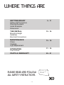 4
4
-
 5
5
-
 6
6
-
 7
7
-
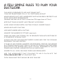 8
8
-
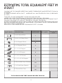 9
9
-
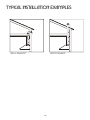 10
10
-
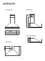 11
11
-
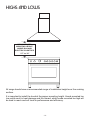 12
12
-
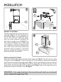 13
13
-
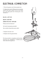 14
14
-
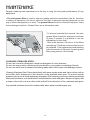 15
15
-
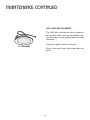 16
16
-
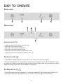 17
17
-
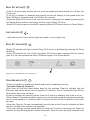 18
18
-
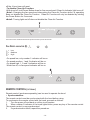 19
19
-
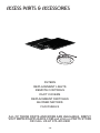 20
20
-
 21
21
-
 22
22
-
 23
23
-
 24
24
-
 25
25
-
 26
26
-
 27
27
-
 28
28
-
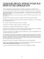 29
29
-
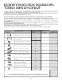 30
30
-
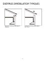 31
31
-
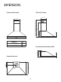 32
32
-
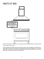 33
33
-
 34
34
-
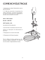 35
35
-
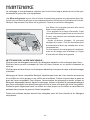 36
36
-
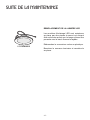 37
37
-
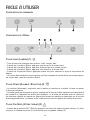 38
38
-
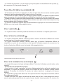 39
39
-
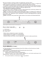 40
40
-
 41
41
-
 42
42
-
 43
43
-
 44
44
-
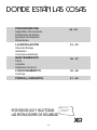 45
45
-
 46
46
-
 47
47
-
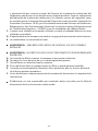 48
48
-
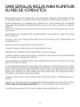 49
49
-
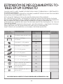 50
50
-
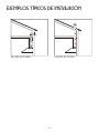 51
51
-
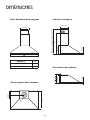 52
52
-
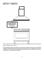 53
53
-
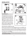 54
54
-
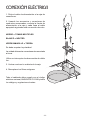 55
55
-
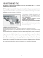 56
56
-
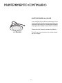 57
57
-
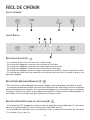 58
58
-
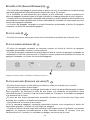 59
59
-
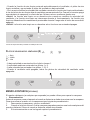 60
60
-
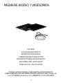 61
61
-
 62
62
-
 63
63
-
 64
64


