Crafstman 41CY4218793 El manual del propietario
- Categoría
- Motosierras eléctricas
- Tipo
- El manual del propietario
Este manual también es adecuado para

769-20650 / 00 02/19
2-CYCLE GAS CHAINSAW
MOTOSIERRA DE GAS DE 2 TIEMPOS
OPERATOR’S MANUAL | MANUAL DEL OPERADOR
S145 | S160 | S180
CMXGSAMNN4214 | CMXGSAMNN4216 | CMXGSAMCX4218
1-888-331-4569 WWW.CRAFTSMAN.COM
IF YOU HAVE QUESTIONS OR COMMENTS, CONTACT US.
SI TIENE DUDAS O COMENTARIOS, CONTÁCTENOS.
ORIGINAL INSTRUCTIONS | TRADUCCIÓN DE LAS INSTRUCCIONES ORIGINALES

2
TABLE OF CONTENTS
Safety . . . . . . . . . . . . . . . . . . . . . . . . . . . . . . . . . . . . . . . . . . . . . . .2
Know Your Unit . . . . . . . . . . . . . . . . . . . . . . . . . . . . . . . . . . . . . . . .7
Essential Terms and Definitions . . . . . . . . . . . . . . . . . . . . . . . . . . .8
Specifications . . . . . . . . . . . . . . . . . . . . . . . . . . . . . . . . . . . . . . . . .9
Assembly . . . . . . . . . . . . . . . . . . . . . . . . . . . . . . . . . . . . . . . . . . . .10
Oil and Fuel . . . . . . . . . . . . . . . . . . . . . . . . . . . . . . . . . . . . . . . . . .11
Starting and Stopping . . . . . . . . . . . . . . . . . . . . . . . . . . . . . . . . . .12
Operation . . . . . . . . . . . . . . . . . . . . . . . . . . . . . . . . . . . . . . . . . . .13
Maintenance . . . . . . . . . . . . . . . . . . . . . . . . . . . . . . . . . . . . . . . . .19
Cleaning and Storage . . . . . . . . . . . . . . . . . . . . . . . . . . . . . . . . . .27
Troubleshooting . . . . . . . . . . . . . . . . . . . . . . . . . . . . . . . . . . . . . .28
Warranty . . . . . . . . . . . . . . . . . . . . . . . . . . . . . . . . . . . . . . . . . . . .29
Service Numbers . . . . . . . . . . . . . . . . . . . . . . . . . . . . . .Back Cover
All information, illustrations, and specifications in this manual are based
on the latest product information available at the time of printing. We
reserve the right to make changes at any time without notice.
The product may vary slightly from the illustrations contained in this
manual.
SAFETY
SPARK ARRESTOR NOTE
NOTE: For users on U.S. Forest Land and in the states of
California, Maine, Oregon and Washington. All U.S. Forest Land
and the state of California (Public Resources Codes 4442 and
4443), Oregon and Washington require, by law that certain internal
combustion engines operated on forest brush and/or grass-covered
areas be equipped with a spark arrestor, maintained in effective
working order, or the engine be constructed, equipped and
maintained for the prevention of fire. Check with your state or local
authorities for regulations pertaining to these requirements. Failure
to follow these requirements could subject you to liability or a fine.
This unit is factory equipped with a spark arrestor. If it requires
replacement, contact your local service dealer to install the
appropriate muffler assembly.
Read the operator’s manual and follow all warnings and safety
instructions. Failure to do so can result in serious injury to the
operator and/or bystanders.
SYMBOL MEANING
The purpose of safety symbols is to attract your attention to
possible dangers. The safety symbols, and their explanations,
deserve your careful attention and understanding. The safety
warnings do not by themselves eliminate any danger. The
instructions or warnings they give are not substitutes for proper
accident prevention measures.
WARNING:
This product can expose you to
chemicals including engine exhaust, which is known to the
State of California to cause cancer, and carbon monoxide,
which is known to the State of California to cause birth
defects or other reproductive harm. For more information
go to www.P65Warnings.ca.gov.
WARNING:
Signals a SERIOUS hazard.
Failure to obey a safety WARNING symbol CAN result in
serious injury to yourself or to others.
CAUTION: Signals a MODERATE hazard.
Failure to obey a safety CAUTION symbol MAY result in
property damage or injury to yourself or to others.
NOTE: Advises you of information or instructions vital to the
operation or maintenance of the equipment.
DANGER:
Signals an EXTREME hazard.
Failure to obey a safety DANGER symbol WILL result in
serious injury or death to yourself or to others.
NOTE: This operator's manual covers multiple models. Features
may vary by model. Not all features in this manual are applicable
to all models. The model depicted may differ from yours.

3
SAFETY WARNINGS FOR GAS UNITS
• Store fuel only in containers specifically designed and approved
for the storage of such materials.
• Always stop the engine and allow it to cool before filling the
tank. Never remove the fuel tank cap or add fuel when the
engine is hot. Always loosen the fuel tank cap slowly to relieve
any pressure in the tank before fueling.
• Always mix and add fuel in a clean, well-ventilated outdoor area
where there are no sparks or flames. DO NOT smoke.
• Never operate the unit without the fuel cap securely in place.
• Avoid creating a source of ignition for spilled fuel. Wipe up any
spilled fuel from the unit immediately, before starting the unit.
Move the unit at least 30 ft. (9.1 m) from the fueling source and
site before starting the engine. DO NOT smoke.
• Never start or run the unit inside a closed room or building.
Breathing exhaust fumes can kill. Operate this unit only in a well-
ventilated outdoor area.
READ ALL INSTRUCTIONS BEFORE OPERATING
• Read the instructions carefully. Be familiar with the controls and
proper use of the unit. Know how to stop the unit and disengage
the controls quickly.
• Stay alert. Do not operate this unit when tired, ill or under the
influence of alcohol, drugs or medication.
• Never allow children to operate the unit. Never allow adults to
operate the unit without proper instruction.
• All guards and safety attachments must be installed properly
before operating the unit.
• Inspect the unit before use. Check for damaged parts. Check for
fuel leaks. Make sure all parts operate properly. Make sure all
fasteners are in place and secure. Make sure all moving parts are
properly aligned and are not bound. Replace parts that are cracked,
chipped, or damaged in any way. Have all damaged or improperly
working parts repaired or replaced by an authorized service center.
Do not operate the unit with loose or damaged parts.
• Be aware of risk of injury to the head, hands and feet.
• Carefully inspect the area before starting the unit. Remove
rocks, broken glass, nails, wire, string and other objects that
may be thrown or become entangled with the unit.
• Clear the area of children, bystanders and pets; keep them
outside a 50-foot (15 m) radius, at a minimum. Even then, they are
still at risk from thrown objects. Encourage bystanders to wear
eye protection. If you are approached, stop the unit immediately.
• Squeeze the throttle control and check that it returns
automatically to the idle position. Make all adjustments or
repairs before using the unit.
• This unit is intended for occasional, household use only.
WHILE OPERATING
• Wear safety glasses or goggles that meet current ANSI / ISEA
Z87.1 standards and are marked as such. Wear ear/hearing
protection when operating this unit. Wear a face mask or dust
mask if the operation is dusty. Use a hard hat or other type of
safety helmet.
• Wear safety boots and protective gloves. Wear heavy, snug-
fitting clothes, including long pants and a long-sleeve shirt. Do
not wear loose clothing, jewelry, short pants, sandals or go
barefoot. Secure hair above shoulder level.
• Make sure the saw chain is not in contact with anything before
starting the unit.
• Use the unit only in daylight or good artificial light.
• Avoid accidental starting. Be in the starting position whenever
pulling the starter rope. The operator and unit must be in a
stable position while starting. Refer to Starting and Stopping.
• Use the right tool. Only use this tool for its intended purpose: to
cut wood. Do not use the unit for cutting plastic, masonry or
other non-wood building materials. Only use the unit as
described in this manual.
• Keep hair, face, hands, feet and all other body parts away from
the saw chain when the unit is running. Do not touch or try to
stop moving parts.
• Do not touch the engine or muffler. These parts get extremely
hot from operation, even after the unit is turned off.
• Do not operate the unit faster than the speed needed to do the
job. Do not run the unit at high speed when not in use.
• Do not force the unit, especially near the end of a cut. It will do a
better, safer job when used at the intended rate.
• Always turn the unit off when operation is delayed or when
carrying the unit from one location to another. Make sure all
moving parts come to a complete stop.
• Before setting the unit down, always make sure the engine is off
and all moving parts have stopped.
• Turn the engine off and disconnect the spark plug for
maintenance or repair.
• Carry the unit by the front handle with the muffler positioned
away from the body and the guide bar positioned to the rear.
Cover the guide bar and saw chain with the scabbard when
carrying the unit.
• If the unit strikes or becomes entangled with a foreign object,
stop the unit immediately. Check for damage. If damaged, do
not restart or operate the unit until it is repaired. Do not operate
the unit with loose or damaged parts.
• Use only original equipment manufacturer (OEM) replacement
parts and accessories for this unit. These are available from your
authorized service dealer. Use of any other parts or accessories
could lead to serious injury to the user, or damage to the unit,
and void the warranty.
• Keep the unit clean. Carefully remove vegetation and other
debris that could block moving parts.
• To reduce fire hazard, replace a faulty muffler and spark arrestor.
Keep the engine and muffler free from grass, leaves, excessive
grease or carbon build up.
• If the unit starts to vibrate abnormally, stop the unit immediately.
Inspect the unit for the cause of the vibration. Vibration is
generally an indicator of trouble.
• Keep the work area clean. Cluttered areas invite injuries. Do not
start cutting until the work area is clear and free from
obstructions. Make sure there is secure footing and a planned
retreat path from falling trees or branches.
• Do not cut near electrical cables or power lines. Keep at least 50
feet (15 m) away from all power lines.
• IMPORTANT SAFETY INSTRUCTIONS •
WARNING:
When using the unit, all safety
instructions must be followed. Please read these
instructions before operating the unit in order to ensure the
safety of the operator and any bystanders. Please keep
these instructions for later use.
WARNING:
Use caution when handling fuel.
Gasoline is highly flammable and its vapors can explode if
ignited. Take the following precautions:

4
• For safer, more effective performance, make sure the guide bar
and chain are properly cleaned, lubricated, tightened and
sharpened. Check the guide bar and chain at frequent intervals
for proper adjustment.
• When cutting a limb that is under tension, use extreme caution.
When the tension is released, the limb could spring back and
strike the operator, causing severe injury or death.
• Use extreme caution when cutting small-sized brush and
saplings, as slender material may catch the saw chain and be
whipped toward the operator or pull the operator off balance.
• This saw is classified by UL as a Class 1C saw in accordance
with CSA Z62.1-03. It is intended for infrequent use by
homeowners, cottagers and campers, and for general
applications such as clearing, pruning, cutting firewood, etc. It is
not intended for prolonged use. If the intended use involves
prolonged periods of operation, this may cause circulatory
problems in the user’s hands due to vibration.
• Never remove, modify or make inoperative any safety device
furnished with the unit.
• Do not use the unit in the presence of flammable liquids or gases.
• Do not attempt operations beyond the operator’s capacity or
experience.
• Do not operate a unit that is damaged, improperly adjusted or
not completely and securely assembled. Make sure moving
parts stop when the unit is turned off. Do not use the unit if it
does not turn on and off properly. Have defective parts replaced
by an authorized service dealer.
KICKBACK SAFETY
Understanding Kickback
A basic understanding of kickback can help reduce or eliminate the
element of surprise and the chance of kickback-related injury.
Sudden surprise contributes to accidents.
• Rotational Kickback can happen when the upper tip of the
guide bar contacts an object while the chain is moving (Fig. A).
This can cause the chain to dig into the object and momentarily
stop moving. The guide bar is then kicked up and back toward
the operator in a lightning-fast reverse reaction.
• Linear Kickback can happen when the wood on either side of a
cut closes in and pinches the moving saw chain along the top of
the guide bar (Fig. B). This can cause the chain to instantly stop.
The chain force is then reversed, causing the saw to move in the
opposite direction, sending the saw straight back toward the
operator.
• Pull-In can happen when the moving chain on the bottom of the
guide bar hits a foreign object inside the wood. This can cause
the chain to suddenly stop. The saw is then pulled forward and
away from the operator, which could potentially result in the loss
of control of the saw.
Kickback Safety Precautions
Take the following steps to reduce the chance of accident or injury:
• Do not rely exclusively upon the safety devices built into the unit.
• Do not cut above shoulder height.
• Do not overreach. Always keep proper footing and balance. Take
extra care when working on steep slopes or inclines. Do not
operate the unit in a tree or on a ladder unless specifically
trained to do so.
• Do not make cuts with the tip of the guide bar.
• Make sure the area of operation is free from obstructions. Do not
let the tip of the guide bar contact any object, such as a log,
branch, the ground or other obstruction.
• Always inspect the wood before cutting. Foreign objects could
damage the unit or cause serious personal injury. Never cut
through nails, metal rods, railroad ties or pallets.
• Do not operate the unit with one hand! Serious injury to the
operator, helpers or bystanders may result from one-handed
operation. This unit is intended for two-handed use. Always grip
the unit firmly with both hands when the unit is running. Hold the
front handle with the left hand and the rear handle with the right
hand. Firmly encircle the handles with the thumbs and fingers.
Do not let go. A firm grip will help maintain control of the unit
and reduce the chance of kickback.
• Stand slightly to the left of the unit to avoid being in the direct
line of the saw chain.
• Never start the saw when the guide bar is inside an existing cut.
Be extremely careful when re-entering a cut.
• Always begin a cut with the unit running at full speed. Fully
squeeze the throttle control and maintain a steady cutting
speed. Slower speeds increase the chance of kickback.
• Keep the saw housing pressed firmly against the wood.
• Do not cut more than one log or branch at a time.
• Do not twist the unit when removing the guide bar from a cut.
Fig. A
Fig. B
Rotational
Kickback
Kickback
Danger Zone
Saw Chain
Direction
Linear
Kickback
Pinch
WARNING:
Kickback may occur when the
nose or tip of the guide bar touches an object, or when the
wood closes in and pinches the saw chain in the cut. In
some cases, tip contact may cause a lightening-fast
reverse action, kicking the guide bar rapidly back to wards
the operator. Pinching the saw chain along the top of the
guide bar may push the guide bar rapidly back towards the
operator. Either of these reactions may cause a loss of
control over the saw, which could result in serious injury to
the user. Contact with foreign objects within the wood can
also induce a loss of chain saw control.

5
• Watch out for shifting objects (logs, branches, etc.) that might
pinch or fall onto the saw chain during operation.
• Only use wedges made of wood or plastic. Do not use metal to
hold a cut open.
• Follow the manufacturer’s sharpening and maintenance
instructions for the saw chain.
• Only use replacement bars and chains specified by the
manufacturer or the equivalent. These are available from
authorized service dealers. Use of any unauthorized parts or
accessories could lead to serious injury to the operator or
damage to the unit and will void the warranty.
• Use devices that reduce the risks associated with kickback,
such as low-kickback chains, guide bar nose guards, chain
brakes and low-kickback guide bars. There are no other
replacement components for achieving kickback protection in
accordance with CSA Z62.3.
• A low-kickback saw chain is a chain that has met the kickback
performance requirements of ANSI/OPEI B175.1-2012 when
tested according to the provisions specified in ANSI/OPEI
B175.1-2012. A low-kickback saw chain is a chain that is also in
accordance with CSA Z62.3. Do not use a replacement saw
chain unless it has met these requirements for this specific
model or has been designated as a low-kickback replacement
saw chain in accordance with ANSI/OPEI B175.1-2012. As saw
chains are sharpened, some of the low-kickback qualities are
lost and extra caution should be used.
• Do not install a bow guide on this unit. Bow guides have larger
kickback zones, which increase the chance of kickback and
serious injury. This increase is not significantly reduced by using
a low-kickback saw chain. Using a bow guide on this unit is
extremely dangerous.
OTHER SAFETY WARNINGS
• Maintain the unit with care. Follow all maintenance instructions
in this manual.
• Do not perform maintenance procedures other than those
described in this manual. All service, other than the maintenance
procedures described in this manual, should be performed by an
authorized service dealer.
• Do not use the unit if it is not working correctly, has been
dropped, damaged, left outdoors or dropped into water. Have
the unit serviced by an authorized service dealer.
• Never remove, modify or make inoperative any safety device
furnished with the unit.
• Before inspecting, maintaining, cleaning, storing, transporting or
replacing any parts on the unit:
1. Stop the unit. Refer to Starting and Stopping.
2. Make sure all moving parts have stopped.
3. Allow the unit to cool.
4. Disconnect the spark plug wire.
• Secure the unit while transporting.
• Always use the scabbard on the guide bar and saw chain during
transportation and storage.
• Always store the unit and fuel in a cool, dry and well-ventilated
space. Do not store fuel, or a unit with fuel in the tank, indoors
where fumes may reach open flames (pilot lights, etc.) or sparks
(switches, electrical motors, etc.).
• Store the unit in a dry place, secured or at a height to prevent
unauthorized use or damage. Keep the unit out of the reach of
children.
• Never douse or squirt the unit with water or any other liquid. Keep
handles dry, clean and free from debris, oil, fuel and grease. Clean
the unit after each use. Refer to Cleaning and Storage. Do not use
solvents or strong detergents.
• Keep these instructions. Refer to them often and use them to
instruct other users. If you loan this unit to others, also loan
them these instructions.
SAVE THESE INSTRUCTIONS

6
• SAFETY & INTERNATIONAL SYMBOLS •
This operator's manual describes safety and international symbols and pictographs that may appear on this product. Read the operator's
manual for complete safety, assembly, operating and maintenance and repair information.
SYMBOL MEANING SYMBOL MEANING
• SAFETY ALERT SYMBOL
Indicates danger, warning or caution. May be used in
conjunction with other symbols or pictographs.
• READ OPERATOR'S MANUAL
WARNING: Read the operator’s
manual(s) and follow all warnings and safety
instructions. Failure to do so can result in serious
injury to the operator and/or bystanders.
• WEAR HEAD, EYE AND HEARING PROTECTION
WARNING: Thrown objects and loud
noise can cause severe eye injury and hearing loss.
Wear eye protection meeting current ANSI Z87.1
standards and ear protection when operating this unit.
Wear head protection when operating this unit; falling
objects can cause severe head injury. Use a full face
shield when needed.
• UNLEADED FUEL
Always use clean, fresh unleaded fuel.
• OIL
Refer to operator’s manual for the proper type of oil.
• DO NOT USE E85 FUEL IN THIS UNIT
WARNING:
It has been proven that fuel
containing greater than 10% ethanol will likely
damage this engine and void the warranty.
• ON/OFF STOP CONTROL
ON / START / RUN
• ON/OFF STOP CONTROL
OFF or STOP
• PRIMER BULB
Push primer bulb, fully and slowly, 10 times.
• CHOKE CONTROL
• Pulled Out - FULL choke position
• Pushed In - RUN position
• KEEP BYSTANDERS AWAY
WARNING:
Keep all bystanders,
especially children and pets, at least 50 feet (15 m)
from the operating area.
• USE BOTH HANDS
WARNING: Always use both hands
while operating the unit. Never use only one hand to
operate the unit.
• KICKBACK
WARNING:
Contact of the guide bar tip
with any object should be avoided. Tip contact may
cause the guide bar to move suddenly upward and
backward, which may cause serious injury.
• CHAIN OIL ADJUSTMENT INDICATOR
The chain must be continously coated with oil to
function properly. Make sure to set the oil adjustment
screw to allow a sufficient amount of oil to flow
continuously onto the chain.
• CHAIN BRAKE
The chain brake immediately stops the moving saw
chain in emergency situations. To manually engage
the chain brake, push the chain brake lever forward
completely. To disengage the chain brake, pull the
chain brake lever back completely.
• CHAIN DIRECTION
Make sure the saw chain faces the direction shown
when installed on the guide bar. Refer to Installing the
Guide Bar and Saw Chain in the Maintenance section.
• CHAIN TENSIONING
Always keep the saw chain properly tensioned. Turn
the chain-tensioning screw clockwise to tighten the
saw chain. Turn the chain-tensioning screw
counterclockwise to loosen the saw chain.

Fuel Cap
Front Handle
Starter Rope Grip
Throttle Control
Muffler
On/Off Switch
Primer Bulb
Scabbard
Choke Knob
Guide Bar Tip
Guide Bar
Saw Chain
Bar Cover
Chain Oil Cap
Chain-Tensioning Screw
Chain Oil Adjustment Screw
Throttle Lockout
Rear Handle /
Boot Loop
Chain Brake Lever /
Front Hand Guard
Bar-Retaining Nuts
Chain Catcher
Carrying Case*
Spiked Bumper /
Bucking Spike
Air Filter Cover
(Spark Plug and Air Filter)
*Not included with
S145 (CMXGSAMNN4214) or
S160 (CMXGSAMNN4216)
Rear Hand Guard
7
KNOW YOUR UNIT
APPLICATIONS
• Felling and limbing trees
• Cutting logs (bucking)
• Pruning trees
ASSEMBLY TOOLS REQUIRED:
• Flat-head screwdriver or multi-purpose tool
(provided)

8
• CHAIN SAW - A tool designed to cut wood with a saw chain. A chain saw is an integrated unit comprised of a power source, saw chain,
guide bar, and handles that are designed to be held by two hands during operation.
• CHAIN SAW POWERHEAD - A chain saw without the saw chain and guide bar.
• DRIVE SPROCKET - A toothed wheel that drives the saw chain.
• FRONT HANDLE - A support handle located toward the front of the chain saw.
• REAR HANDLE - A support handle located toward the rear of the chain saw.
• CHAIN BRAKE LEVER / FRONT HAND GUARD - A structural barrier between the front handle and the guide bar. The front hand guard
helps protect the operator’s left hand if it slips off the front handle while the unit is running. The chain brake lever is also used to manually
engage the chain brake.
• CHAIN BRAKE - A device that reduces the chance of injury if kickback occurs, by stopping the saw chain in milliseconds. The chain
brake is designed to engage automatically in response to kickback. The chain brake can also be activated by pushing the chain brake
lever forward, either intentionally or if the operator’s hand strikes the lever during kickback.
• REAR HAND GUARD - A structural barrier below the rear handle. The rear hand guard helps protect the operator’s right hand if the saw
chain breaks or disengages from the guide bar during operation.
• GUIDE BAR - A solid railed structure that supports and guides the saw chain.
• GUIDE BAR TIP - The tip or end of the guide bar.
• REDUCED-KICKBACK GUIDE BAR - A guide bar that has been demonstrated to reduce kickback significantly.
• SAW CHAIN - A loop of chain with teeth designed to cut wood, which is driven by the engine and is supported by the guide bar. The saw
chain is composed of drive links, cutters and side links, held together by rivets.
• LOW-KICKBACK SAW CHAIN - A saw chain that complies with the kickback performance requirements of ANSI/OPEI B175.1-2012 when
tested on a representative sample of chain saws. Low-kickback saw chain significantly reduces the chance of kickback and the intensity
of kickback, due to specially designed depth gauges and guard links.
• REPLACEMENT SAW CHAIN - A saw chain that complies with the kickback performance requirements of ANSI/OPEI B175.1-2012 when
tested with specific chain saws. It may not meet the ANSI/OPEI performance standards when used with other chain saws.
• SPIKED BUMPER - The pointed tooth (or teeth), at the front of the chain saw, used during felling and bucking to help pivot the saw and
maintain a stable position while cutting.
• CHAIN CATCHER - A device designed to intercept a whipping chain. The chain catcher reduces the chance of injury if the saw chain
breaks or disengages from the guide bar during operation.
• OILER CONTROL - A system for oiling the saw chain and guide bar.
• ON/OFF SWITCH - A device that immediately stops the engine when moved to the OFF position. The saw chain will then coast to a stop.
The On/Off switch must be moved to the On position to start the engine.
• THROTTLE CONTROL - A device used in conjunction with the throttle lockout to accelerate the engine. Releasing the throttle control
returns the engine to idle.
• THROTTLE LOCKOUT - A device that prevents accidental acceleration of the engine. The throttle control cannot be squeezed unless the
throttle lockout is engaged.
• SPARK ARRESTER SCREEN - A device that retains carbon and other flammable particles over 0.023 inches (0.6mm) in size from the
engine exhaust flow. Compliance with local, state and federal laws and/or regulations governing the use of a spark arrester screen is the
user’s responsibility. Refer to Spark Arrestor Note in the Safety section for additional information.
• KICKBACK - A sudden backward and/or upward motion of the guide bar and saw chain. Kickback can occur if the upper portion of the
guide bar tip touches an object while the saw chain is spinning (rotational kickback). Kickback can also occur if the wood closes in and
pinches the saw chain inside the cut (linear kickback).
• ROTATIONAL KICKBACK - A sudden backward and upward motion of the guide bar and saw chain. Rotational kickback can occur if the
upper portion of the guide bar tip touches an object while the saw chain is spinning. The guide bar and saw chain are then kicked up and
back toward the operator in a lightning-fast reverse reaction.
• LINEAR KICKBACK (PINCH KICKBACK) - A sudden backward motion of the guide bar and saw chain. Linear (pinch) kickback can occur
if the wood closes in and pinches the saw chain inside a cut. The saw is then sent straight back toward the operator.
• NORMAL CUTTING POSITION - The positions assumed while making bucking and felling cuts.
• FELLING - The process of cutting down a tree.
• NOTCHED UNDERCUT - The first cutting procedure in the tree felling process. A notch is cut on one side of the tree to direct its fall.
• FELLING BACK CUT - The final cut in the tree felling process. The felling back cut is made on the opposite side of the tree from the
notched undercut.
• BUCKING - The process of cutting a felled tree or log into lengths.
• LIMBING - The process of removing branches from a fallen tree.
• PRUNING - The process of cutting limbs from a living tree.
ESSENTIAL TERMS AND DEFINITIONS

9
SPECIFICATIONS*
* All specifications are based on the latest product information available at the time of printing. We reserve the right to make changes at any
time without notice.
Engine Type . . . . . . . . . . . . . . . . . . . . . . . . . . . . . . . . . . . . . . . . . . . . . . . . . . . . . . . . . . . . . . . . . . . . . . . . . . . . . . . . . . . . . . . Air-Cooled, 2-Cycle
Displacement. . . . . . . . . . . . . . . . . . . . . . . . . . . . . . . . . . . . . . . . . . . . . . . . . . . . . . . . . . . . . . . . . . . . . . . . . . . . . . . . . . . . . . . 42 cc (2.56 cu. in.)
Spark Plug Gap. . . . . . . . . . . . . . . . . . . . . . . . . . . . . . . . . . . . . . . . . . . . . . . . . . . . . . . . . . . . . . . . . . . . . . . . . . . . . . . . . . . . 0.025 in. (0.635 mm)
Spark Plug . . . . . . . . . . . . . . . . . . . . . . . . . . . . . . . . . . . . . . . . . . . . . . . . . . . . . . . . . . . . . . . . . . . . . . . . . . Champion® RZ7C or equivalent plug
Lubrication . . . . . . . . . . . . . . . . . . . . . . . . . . . . . . . . . . . . . . . . . . . . . . . . . . . . . . . . . . . . . . . . . . . . . . . . . . . . . . . . . . . . . . . . . Bar and Chain Oil
Fuel/Oil Ratio . . . . . . . . . . . . . . . . . . . . . . . . . . . . . . . . . . . . . . . . . . . . . . . . . . . . . . . . . . . . . . . . . . . . . . . . . . . . . . . . . . . . . . . . . . . . . . . . . . 40:1
Fuel Tank Capacity . . . . . . . . . . . . . . . . . . . . . . . . . . . . . . . . . . . . . . . . . . . . . . . . . . . . . . . . . . . . . . . . . . . . . . . . . . . . . . . . . . . . . . 9 oz. (270 mL)
Chain Oil Reservoir Capacity . . . . . . . . . . . . . . . . . . . . . . . . . . . . . . . . . . . . . . . . . . . . . . . . . . . . . . . . . . . . . . . . . . . . . . . . . . . . . 6.5 oz. (200 mL)
Approximate Unit Weight (without fuel or chain oil) . . . . . . . . . . . . . . . . . . . . . . . . . . . . . . . . . . . . . . . . . . . . . . . . 11.75 - 12.75 lbs. (5.3 - 5.8 kg)
Guide Bar Length (S145 / CMXGSAMNN4214) . . . . . . . . . . . . . . . . . . . . . . . . . . . . . . . . . . . . . . . . . . . . . . . . . . . . . . . . . . . . . . . 14 in. (35.6 cm)
Guide Bar Length (S160 / CMXGSAMNN4216) . . . . . . . . . . . . . . . . . . . . . . . . . . . . . . . . . . . . . . . . . . . . . . . . . . . . . . . . . . . . . . . 16 in. (40.6 cm)
Guide Bar Length (S180 / CMXGSAMCX4218). . . . . . . . . . . . . . . . . . . . . . . . . . . . . . . . . . . . . . . . . . . . . . . . . . . . . . . . . . . . . . . . 18 in. (45.7 cm)
Saw Chain Pitch . . . . . . . . . . . . . . . . . . . . . . . . . . . . . . . . . . . . . . . . . . . . . . . . . . . . . . . . . . . . . . . . . . . . . . . . . . . . . . . . . . . . . . . 3/8 in. (9.5 mm)
Saw Chain Gauge . . . . . . . . . . . . . . . . . . . . . . . . . . . . . . . . . . . . . . . . . . . . . . . . . . . . . . . . . . . . . . . . . . . . . . . . . . . . . . . . . . . 0.050 in. (1.3 mm)
REPLACEMENT PARTS
Please contact the Customer Support Department to order replacement parts.
Part #
713-05277 . . . . . . . . . . . . . . . . . . . . . . . . . . . . . . . . . . . . . . . . . . . . . . . .
713-05276 . . . . . . . . . . . . . . . . . . . . . . . . . . . . . . . . . . . . . . . . . . . . . . . .
713-05042 . . . . . . . . . . . . . . . . . . . . . . . . . . . . . . . . . . . . . . . . . . . . . . . .
795-00782 . . . . . . . . . . . . . . . . . . . . . . . . . . . . . . . . . . . . . . . . . . . . . . . .
795-00542 . . . . . . . . . . . . . . . . . . . . . . . . . . . . . . . . . . . . . . . . . . . . . . . .
795-00543 . . . . . . . . . . . . . . . . . . . . . . . . . . . . . . . . . . . . . . . . . . . . . . . .
753-08105 . . . . . . . . . . . . . . . . . . . . . . . . . . . . . . . . . . . . . . . . . . . . . . . .
Description
Saw Chain (14 in. / 35.6 cm)
Saw Chain (16 in. / 40.6 cm)
Saw Chain (18 in. / 45.7 cm)
Guide Bar (14 in. / 35.6 cm)
Guide Bar (16 in. / 40.6 cm)
Guide Bar (18 in. / 45.7 cm)
Bar-Retaining Nuts

10
ASSEMBLY
ADJUSTING THE CHAIN TENSION: INITIAL USE
The saw chain must be properly tensioned before attempting to
start or operate the unit. The saw chain may also require additional
tensioning as the saw chain heats up during operation. Refer to
Adjusting the Chain Tension instructions in the Maintenance section.
TESTING THE CHAIN BRAKE
Always test the chain brake before using the unit.
1. Set the unit on a flat, level surface.
2. Make sure the chain brake lever is pulled back in the
disengaged position (Fig. 1).
3. Start the unit. Refer to Starting Instructions in the Starting and
Stopping section. Maintain a proper grip. Refer to Holding the
Unit in the Operation section.
4. While the unit is running, squeeze the throttle control to 1/3
throttle and then engage the chain brake by pushing the chain
brake lever forward with the left hand (Fig. 1). The chain should
stop moving abruptly.
IF... If the chain stops moving, the chain brake is working correctly.
IF... If the chain does not stop moving, have the unit serviced by an
authorized service dealer.
5. Stop the engine and return the chain brake to the disengaged
position. Refer to Stopping Instructions in the Starting and
Stopping section.
WARNING:
Always activate the chain brake slowly and
deliberately. Keep the saw chain from touching anything.
Do not let the chain saw tip forward.
ADDING BAR AND CHAIN OIL: INITIAL USE
This unit comes from the factory with the chain oil reservoir empty.
Fill the chain oil reservoir with bar and chain oil before starting or
using the unit. Refer to Adding Bar and Chain Oil instructions in the
Maintenance section.
Fig. 1
Engaged
Disengaged
Chain Brake Lever

11
OIL AND FUEL
FUELING THE UNIT
1. Position the unit with the fuel cap facing up.
2. Slowly remove the fuel cap (Fig. 2).
3. Place the fuel container spout into the fuel tank fill hole and fill
the tank.
NOTE: Do not overfill the tank.
4. Wipe up any fuel that may have spilled.
5. Reinstall the fuel cap.
6. Move the unit at least 30 ft. (9.1 m) from the fuel container and
the fueling site before starting the engine.
OIL AND FUEL MIXING INSTRUCTIONS
The use of old and/or improperly mixed fuel is the most common cause
of performance problems. Use only fresh, clean unleaded gasoline.
Follow the instructions carefully for the proper gasoline/oil mixture.
Definition of Blended Fuels
Today's fuels are often a blend of gasoline and oxygenates such as
ethanol, methanol or MTBE (ether). Alcohol-blended fuel absorbs
water. As little as 1% water in the fuel can make fuel and oil
separate, forming acids when stored. ALWAYS use fresh fuel (less
than 30 days old).
NOTE: Dispose of old fuel according to federal, state and local
regulations.
Using Blended Fuels
If using a blended fuel:
• Always use the fresh fuel mix explained in this operator's manual
• Use the fuel additive STA-BIL® or an equivalent
• Always agitate the fuel mix before fueling the unit
Using Fuel Additives
The container of 2-cycle oil provided with this unit includes a fuel
additive to help inhibit corrosion and minimize gum deposits.
Always use the brand of 2-cycle oil that came with this unit. If this is
unavailable, use a 2-cycle oil designed for air-cooled engines and
mix it with a fuel additive, such as STA-BIL Fuel Stabilizer or an
equivalent. Add 0.8 oz. (23 ml) of fuel additive per gallon of fuel,
according to the instructions on the container. NEVER add fuel
additives directly to the unit's fuel tank.
Mixing the Fuel
NOTE: This unit comes with a 3.2 oz. (95 ml) container of 2-cycle
oil. To obtain the correct fuel mixture described below, pour the
entire container into one gallon of unleaded gasoline.
Thoroughly mix the proper ratio of unleaded gasoline with 2-cycle
engine oil. Do not mix them directly in the unit’s fuel tank. Use a
separate fuel can. Use a 40:1 gasoline/oil ratio. See the table below
for specific gasoline and oil mixing ratios.
Unleaded gasoline 2-cycle oil
1 gallon U.S.
(3.8 liters)
3.2 fl. oz.
(95 ml)
1 liter 25 ml
MIXING RATIO - 40:1
CAUTION:
For proper engine operation and maximum
reliability, pay strict attention to the gasoline and oil mixing
instructions on the 2-cycle oil container. Using improperly
mixed fuel can severely damage the engine.
WARNING:
Gasoline is extremely flammable. Ignited
vapors may explode. Always stop the engine and allow it
to cool before filling the fuel tank. Do not smoke while
filling the tank. Keep sparks and open flames at a distance
from the area.
WARNING:
Remove the fuel cap slowly to avoid injury
from fuel spray. Never operate the unit without the fuel cap
securely in place.
WARNING:
Add fuel in a clean, well-ventilated outdoor
area. Wipe up any spilled fuel immediately. Avoid creating
a source of ignition for spilled fuel. Do not start the engine
until fuel vapors dissipate.
CAUTION:
DO NOT USE E85 FUEL IN THIS UNIT. It
has been proven that fuel containing greater than 10%
ethanol will likely damage this engine and void the warranty.
Fig. 2
Fuel Cap

12
STARTING AND STOPPING
Fig. 5
Starting
Position
Starter
Rope Grip
Boot Loop
STARTING INSTRUCTIONS
Before Starting the Unit
1. Mix gasoline with oil. Refer to Oil and Fuel Mixing Instructions.
2. Fill the fuel tank. Refer to Fueling the Unit.
3. Fill the chain oil reservoir with bar and chain oil. Refer to Adding
Bar and Chain Oil in the Maintenance section.
4. Make sure the chain brake is disengaged. Refer to Testing the
Chain Brake in the Assembly section.
Starting the Unit
1. Move the On/Off switch to the On position (Fig. 3).
2. Slowly press and release the primer bulb 10 times (Fig. 4). If fuel
cannot be seen in the primer bulb, press and release the primer
bulb until fuel is visible.
3. Pull the choke knob out to Position 1 (Fig. 4).
NOTE: DO NOT touch the throttle control (Fig. 3) until step 10.
4. Set the unit on a flat, level surface. Clear the area of any objects
that could contact the saw chain.
5. Crouch in the starting position (Fig. 5). Hold the front handle with
the left hand. Hold the starter rope grip with the right hand.
Insert the right foot into the boot loop to help hold the unit firmly
in place.
6. Pull the starter rope with a controlled and steady motion 5 times
(Fig. 5).
7. Push the choke knob in to Position 2 (Fig. 4).
8. Pull the starter rope with a controlled and steady motion 3 to 5
times to start the engine.
9. Allow the engine to warm up for 30 to 60 seconds.
10. Press and hold the throttle lockout. Lightly squeeze and release
the throttle control to idle the engine.
11. To reduce the chance of injury, engage the chain brake until you
are ready to begin operation. When ready, disengage the chain
brake. Then press the throttle lockout and squeeze the throttle
control to accelerate the engine, as needed.
WARNING:
The saw chain should not move when the
engine runs at idle. If it does move, refer to Adjusting the
Idle Speed in the Maintenance section.
WARNING:
Operate this unit only in a well-ventilated
outdoor area. Carbon monoxide exhaust fumes can be
lethal in a confined area.
WARNING:
Avoid accidentally starting the unit. To avoid
serious injury, the operator and the unit must be in a stable
position when pulling the starter rope (Fig. 5).
WARNING:
Never operate the unit without the guide bar
and saw chain properly installed. Make sure the bar-
retaining nuts are tight and the guide bar cover is securely
assembled. Make sure the saw chain is properly
tensioned. Refer to Adjusting the Chain Tension
instructions in the Maintenance section.
WARNING:
The saw chain will spin after the engine
starts. Keep hands and feet clear of the saw chain and do
not allow the saw chain to contact any object(s).
Fig. 4
Primer Bulb
Position 1
Position 2
Choke Knob
Fig. 3
Throttle Control
Throttle Lockout
On/Off Switch (I = On / O = Off)

13
OPERATION
WARNING: Always wear appropriate eye, hearing, hand,
foot and body protection to reduce the risk of injury when
operating this unit. Wear head protection. Use a full face
shield when needed. Refer to the Safety section for
appropriate safety equipment information.
WARNING:
Make sure the chain oil reservoir is full
before operation. Check the oil level constantly so that it
does not drop below half full. Make sure the chain oil
adjustment screw is set appropriately. Refer to Setting the
Chain Oil Adjustment Screw in the Maintenance section.
The saw chain must be continuously coated with oil to
function properly.
WARNING:
Always check the chain tension and adjust as
necessary before beginning operation. Refer to Adjusting the
Chain Tension in the Maintenance section.
NOTE: The engine is properly warmed up when it accelerates
without hesitation.
IF... the engine hesitates, continue the warm-up.
IF... the engine does not start, repeat the starting procedure.
IF... the engine fails to start after a few attempts, move the choke
knob to Position 2, press the throttle lockout and squeeze the
throttle control. Pull the starter rope with a controlled and steady
motion until the unit starts.
IF... the engine is already warm, make sure the On/Off switch is in
the On position, crouch in the starting position, pull the choke
knob out to Position 1 and then push the choke knob back in to
Position 2. Begin the starting procedure with step 8.
STOPPING INSTRUCTIONS
1. Release the throttle control and allow the engine to idle.
2. Move the On/Off switch to the Off (O) position (Fig. 3). Wait for
the engine and saw chain to come to a complete stop.
Emergency Stopping
1. Push the chain brake lever forward to engage the chain brake.
Refer to Testing the Chain Brake in the Assembly section.
2. Move the On/Off switch to the Off (O) position. Wait for the
engine and saw chain to come to a complete stop.
TIPS FOR BEST RESULTS
• Follow all safety instructions. Refer to the Safety section.
• Only cut wood and materials made of wood. Do not attempt to
cut sheet metal, plastics, masonry or any other non-wood
materials.
• Practice cutting a few small logs before beginning a major
cutting operation. First-time users should practice cutting logs
on a sawhorse or cradle before undertaking other operations.
• Do not attempt to cut trees or logs with diameters larger than:
- 10 in. / 25.4 cm (S145 / CMXGSAMNN4214)
- 12 in. / 30.5 cm (S160 / CMXGSAMNN4216)
- 14 in. / 35.6 cm (S180 / CMXGSAMCX4218)

14
Fig. 8
Correct Stance
Fig. 9
Chain Line
Incorrect Stance
Chain Line
PREPARING THE WORK AREA
• Clear the area of children, bystanders and pets; keep them
outside a 50-foot (15 m) radius, at a minimum. Even then, they
are still at risk from thrown objects. Encourage bystanders to
wear eye protection. If you are approached, stop the unit
immediately. When felling, the safe distance is at least twice the
height of the tallest tree in the work area. When bucking, keep
workers at least 15 feet (4.6 m) apart.
• Keep the work area clean. Cluttered areas invite injuries. Do not
start cutting until the work area is clear and free from
obstructions. Make sure there is secure footing and a planned
retreat path from falling trees or branches.
• Do not cut near electrical cables or power lines. Keep at least 50
feet (15 m) away from all power lines.
• Use the unit only in daylight or good artificial light.
HOLDING THE UNIT
• Firmly encircle the handles with the thumbs and fingers (Fig. 6).
This will help reduce the chance of losing control of the unit if
kickback occurs. Any grip with thumbs and fingers on the same
side of the handles is dangerous (Fig. 7).
• Always grip the unit firmly with both hands when the unit is
running.
• Hold the front handle with the left hand. Keep the left arm
straight to help withstand potential kickback.
• Hold the rear handle with the right hand. Keep the right arm
slightly bent.
• Stand in a stable position with feet apart and firmly planted.
• Do not cut above shoulder height. Do not overreach.
WARNING:
Always use the hand placements specified
below whether the operator is left-handed or right-handed.
This will help keep the operator slightly to the left of the
unit and out of the direct line of the saw chain if kickback
occurs (Fig. 8 and Fig. 9). Always keep all body parts to
the left of the chain line.
CUTTING PROCEDURE BASICS
1. Start the unit. Refer to Starting Instructions in the Starting and
Stopping section.
2. Keep your fingers off the throttle control until you are ready to
make a cut.
3. Accelerate the unit to full speed before cutting.
4. Make sure that oil is flowing onto the guide bar and saw chain. A
small spray should be visible. When using the unit for the first
time, allow 30-60 seconds for the oil to begin flowing.
5. Press the unit against the wood and maintain a firm, steady
pressure through most of the cut. Do not put pressure on the
unit at the end of the cut.
6. Maintain a steady speed throughout the cut. Keep the unit
running through the entire cut.
7. Do not try to force the saw through the wood. Allow the saw
chain to do the cutting. Exert only light pressure. Forcing the cut
could result in damage to the unit or personal injury.
8. Release the throttle control as soon as the cut is completed.
Allow the saw chain to come to a complete stop. The saw chain,
guide bar and engine may experience unnecessary wear if the
unit is run without a cutting load.
Fig. 7
Incorrect Grip
Thumb
Above the
Handle
Fig. 6
Correct Grip
Thumbs Below the Handles

15
FELLING: SAFETY
Felling is the process of cutting down a tree. Follow these safety
precautions to reduce the risk of serious injury, property damage
and damage to electrical lines:
• Do not fell trees with an extreme lean. Do not fell trees with
rotten limbs, loose bark or hollow trunks. Have these trees
pushed or dragged down with heavy equipment.
• Do not cut trees near buildings or electrical lines. Leave these
operations for professionals. If a felled tree does contact an
electrical line, notify the utility company immediately.
• Check the tree for damaged or dead branches that could fall
and cause serious injury.
• Remove dirt, stones, loose bark, nails, wire and other
obstructions from the portion of the tree that will be cut.
• When bucking and felling operations are performed by two or
more persons in the same general area, they should be
separated from each other by a distance of at least twice the
height of the tree to be felled.
• Consider the force and direction of the wind. Consider the lean
and balance of the tree. Consider the location of large branches.
All of these factors influence the direction that the tree will fall. Do
not try to fell a tree in a direction other than its natural fall line.
• Do not fell trees during periods of precipitation or high winds.
• Determine a safe and expedient escape route. Clear the area
around the tree and make sure there are no obstructions
blocking the escape route. Establish a 90º corridor of escape,
approximately 135º from the line of fall (Fig. 10).
• Stay uphill from the tree; it will most likely roll or slide after it falls.
FELLING: PROCEDURE
Small trees, up to 6 - 7 inches (15 - 18 cm) in diameter, are usually
felled in a single cut. Larger trees require a sequence of two cutting
operations: a notched undercut followed by a felling back cut. It
may also be necessary to remove buttress roots.
Step 1: Removing Buttress Roots
Buttress roots are large roots that extend above the ground and
help support the tree. If the tree has large buttress roots that might
impede the felling process, follow these steps to remove them:
1. Make a horizonal cut into the buttress root (Fig. 11). To prevent
the guide bar from being pinched by the weight of the wood,
always make this cut first.
2. Make a vertical cut into the buttress root (Fig. 11).
3. Remove the loose section from the work area.
Step 2: Making the Notched Undercut
This cut determines which direction the tree will fall. Always make
this cut on the side of the tree facing the direction where the tree
should fall. Make the cut at 90º to the line of fall.
1. Make a horizontal cut into the trunk of the tree (Fig. 12). The cut
should be about 1/3 the diameter of the tree and close to the
ground. To prevent the guide bar from being pinched by the
weight of the wood, always make this cut first.
2. Make a 45º cut into the trunk of the tree, above the first cut (Fig.
12). Continue cutting until the two cuts meet.
3. Remove the loose section from the work area.
WARNING:
Never walk in front of a tree with a notched
undercut.
90°
Fig. 10
Planned
Line of Fall
135º From Planned
Line of Fall
Path of Safe
Retreat
Fig. 11
First Cut
Second Cut
Fig. 12
Notched
Undercut
First Cut
Second Cut
1/3 Diameter
135º From Planned
Line of Fall
Direction of Fall
Buttress Root

16
Step 3: Making the Felling Back Cut
This cut fells the tree.
1. Make a horizontal cut into the opposite side of the tree from the
notched undercut (Fig. 13). Make the cut approximately 2 inches
(5 cm) above the bottom of the notched undercut (Fig. 13).
2. As the cut gets close to the notched undercut, only a thin band
of wood will support the tree. This band of wood is referred to as
the hinge (Fig. 13). The hinge helps control the fall of the tree.
Leave approximately 2 inches (5 cm) of hinge in place. Do not
cut through the hinge. Cutting through the hinge could cause the
tree to fall in any direction.
3. Periodically glance up during the felling back cut to see if the
tree is going to fall in the correct direction. If there is a chance
that the tree might not fall in the desired direction, or if the tree
might rock back and bind the chain saw, remove the guide bar
from the cut, stop the unit and use wedges to open the cut and
direct the fall (Fig. 14). Only use soft plastic or wooden wedges.
Drive the wedges into the cut slowly. Once the wedges are in
place and the cut is held open, either carefully reinsert the guide
bar and continue the cut or slowly drive the wedges in further to
push the tree over.
4. As the hinge gets smaller, the tree should begin to fall. When the
tree begins to fall, remove the chain saw from the cut, stop the
engine and set the unit down immediately. Promptly exit the area
along the retreat path, but keep watching the tree as it falls.
WARNING:
Always recheck the area for bystanders,
animals and obstacles before making the felling back cut.
DANGER:
If the tree starts to fall in the wrong direction
and binds the chain saw, leave the unit and evacuate the
area immediately! Do not try to save the chain saw!
LIMBING
Limbing is the process of removing branches from a fallen tree.
1. Leave the larger support limbs under the tree for last (Fig. 16).
These will keep the tree off the ground during the limbing process.
2. Cut one limb at a time. Stand on the opposite side of the tree
from the limb (Fig. 16). Keep the trunk between the operator and
the chain saw. To avoid binding the chain saw, branches under
tension should be cut from the bottom up.
3. Remove the cut limbs from the work area.
WARNING:
Stay clear of spring poles when operating the
unit. Spring poles are branches, logs, roots or saplings that
are bent under tension by other wood (Fig. 15). When the
tension is released, spring poles can strike the operator,
causing serious injury and potentially knocking the chain
saw into the operator’s body. Use extreme caution when
cutting spring poles or when releasing the cause of tension.
Fig. 13
Felling
Back Cut
2 inches
(5 cm)
Fig. 14
Wedge
2 inches
(5 cm)
Hinge
Fig. 16
Fig. 15
Spring Pole
Support Limb

17
BUCKING: PROCEDURE
Cutting Logs Under Stress
When logs are supported on one or both ends, the wood tends to
bend during the cutting process. This can cause the chain saw to
become pinched between the two sides. Pay extra attention.
1. Make the first cut approximately 1/3 the diameter of the log. Do
not cut deeper than 1/3.
• If the log is supported on one end (Fig. 17), make the first cut
from below (underbucking). Refer to Underbucking.
• If the log is supported on two ends (Fig. 18), make the first cut
from above (overbucking). Refer to Overbucking.
2. Make the second cut from the opposite side until the two cuts
meet. If the diameter of the wood is large enough, insert soft
plastic or wooden wedges to hold the cut open and prevent
pinching (Fig. 21). Take care not to touch the wedges with the
saw chain.
Cutting Fully-Supported Logs
When logs are supported along the entire length, extra care should
be taken to make sure the saw chain does not contact the ground
or other support structure (Fig. 19).
1. Cut through the log as much as possible, without cutting into
the ground or support structure. Cut from above (overbucking).
Refer to Overbucking.
2. Roll the log over and finish cutting through the log from above
(overbucking).
BUCKING: SAFETY
Bucking is the process of cutting a fallen tree into logs of desired
lengths. Follow these safety precautions to reduce the risk of
serious injury:
• Clear the area of objects or obstructions that could contact the
guide bar and result in kickback.
• When bucking on a slope, always stand on the uphill side of the
fallen tree.
• If possible, the end of the tree to be cut should be raised off of
the ground. A saw horse is ideal for this purpose. If a saw horse
is not available, use other logs or any remaining limb stumps.
Make sure the tree if firmly supported.
• Do not let the saw chain contact the ground or saw horse.
• Cut one log at a time. Release the throttle control and allow the
saw chain to come to a complete stop before moving on to the
next log.
• Keep feet and all other body parts clear of falling logs.
DANGER:
Use extreme caution when cutting a fallen
tree that is still attached to the root structure. When the
trunk is separated from the roots, the stump has a high
potential for rocking back into the hole created by the
roots. This can result in serious injury or death. Never
stand in the hole left by the roots. Never allow others to
stand near the root structure.
Fig. 17
Log Supported
on One End
First Cut (1/3 Diameter)
Fig. 18
Second Cut
Load
Fig. 19
Overbucking
Fig. 20
Underbucking
Log Supported
Two Ends
First Cut (1/3 Diameter)
Second Cut
Load

18
Fig. 22
PRUNING
Pruning is the process of cutting limbs from a living tree.
1. Make the first cut approximately 6 inches (15 cm) from the tree
trunk. Cut upward, from the underside of the limb. Use the top
of the guide bar to make this cut. Cut a third of the way through
the diameter of the limb (Fig. 22).
2. Make the second cut 2 - 4 inches (5 - 10 cm) farther out on the
limb. Cut downward, from the top of the limb. Use the bottom of
the guide bar to make this cut. Cut completely through the limb
(Fig. 22).
3. Make the third cut as close to the tree trunk as possible. Cut
upward, from the underside of the limb stub. Use the top of the
guide bar to make this cut. Cut a third of the way through the
diameter of the limb (Fig. 22).
4. Make the fourth cut directly above the third cut. Cut downward,
from the top of the limb stub. Use the bottom of the guide bar to
make this cut. Cut completely through the limb stub to meet the
third cut (Fig. 22). This will remove the limb stub.
Third Cut
First Cut
Second Cut
Fourth Cut
WARNING:
Do not cut above shoulder height with a
chain saw. Use a pole saw to cut limbs above shoulder
height or hire a professional. Do not operate the unit in a
tree or on a ladder unless specifically trained to do so.
WARNING:
Falling branches can cause serious injury.
Always wear appropriate head protection. Plan an escape
route away from falling limbs. Do not position any body
parts directly below the limb when cutting.
Fig. 21
Wedge
Overbucking
1. Begin cutting from above, with the bottom of the saw chain
against the top of the log (Fig. 19).
2. Exert light, downward pressure. The saw will tend to pull away
from the operator. Be prepared and hold the saw firmly to
maintain control.
Underbucking
1. Begin cutting from below, with the top of the saw chain against
the bottom of the log (Fig. 20).
2. Exert light, upward pressure. The saw will tend to push toward the
operator. Be prepared and hold the saw firmly to maintain control.

19
MAINTENANCE
MAINTENANCE SCHEDULE
Perform these required maintenance procedures at the frequency
stated in the table. These procedures should also be a part of any
seasonal tune-up.
All service, other than the maintenance procedures described in
this manual, should be performed by an authorized service dealer.
NOTE: Some maintenance procedures may require special tools or
skills. If you are unsure about these procedures, take the unit to
an authorized service dealer. Call 1-888-331-4569 for more
information.
NOTE: Maintenance, replacement, or repair of the emission control
devices and system may be performed by an authorized service
dealer. Call 1-888-331-4569 for more information.
NOTE: Please read the California/EPA statement that came with the
unit for a complete listing of terms and coverage for the
emissions control devices, such as the spark arrestor, muffler,
carburetor, etc.
FREQUENCY MAINTENANCE REQUIRED
Before each
use
• Check for loose screws, nuts or bolts
(tighten as needed)
• Check for damaged or worn parts*
• Check the saw chain sharpness. Refer to
Sharpening the Saw Chain.
• Test the chain brake*. Refer to Testing the
Chain Brake.
• Check the chain tension (adjust as needed).
Refer to Adjusting the Chain Tension.
• Fill the chain oil reservoir (refill frequently).
Refer to Adding Bar and Chain Oil.
• Fill the fuel tank with fresh, properly mixed
fuel. Refer to the Oil and Fuel section.
• Clean the air filter. Refer to Maintaining the
Air Filter.
After each use • Clean the unit and inspect decals. Refer to
Cleaning in the Cleaning and Storage
section.
Every 10 hours • Check the spark plug condition and gap.
Refer to Maintaining the Spark Plug.
• Clean the guide bar groove and oil
passages. Lubricate the sprocket tip. Refer
to Maintaining the Guide Bar.
• Clean the cylinder fins. Refer to Cleaning in
the Cleaning and Storage section.
CUSTOMER RESPONSIBILITY
* If maintenance or replacement is required, have the unit serviced
by an authorized service dealer.
WARNING:
To avoid serious personal injury, always stop
the engine and allow it to cool before cleaning or maintaining
the unit. Never perform cleaning or maintenance while the
unit is running. Disconnect the spark plug wire to prevent
the unit from starting accidentally.
WARNING:
Wear protective clothing and observe all
safety instructions to prevent serious personal injury.

20
ADDING BAR AND CHAIN OIL
The guide bar and saw chain require lubrication to minimize friction.
Never starve the guide bar and chain of lubricating oil. Running the
unit without enough oil will decrease cutting efficiency, shorten the
life of the saw chain, cause rapid dulling of the saw chain and
excessive wear to the guide bar from overheating. An insufficient
amount of lubricating oil is evidenced by smoke, guide bar
discoloration or pitch build-up.
Only use bar and chain oil that is formulated to perform over a wide
range of temperatures with no diluting required in the chain oil
reservoir. Do not use motor oil or any other petroleum-based oil. Do
not use dirty, used or contaminated oil. Damage may occur to the
guide bar or saw chain. Dispose of old oil according to federal, state
and local regulations.
1. Set the unit on a flat, level surface.
2. To prevent debris from entering the chain oil reservoir, use a damp
cloth to clean the chain oil cap and surrounding area.
3. Unscrew the chain oil cap (Fig. 23).
4. Carefully pour the oil into the chain oil reservoir. DO NOT overfill.
5. Reinstall the chain oil cap. Tighten the cap firmly.
6. Wipe up any oil that may have spilled.
DANGER:
Failure to fill the chain oil reservoir will cause
irreparable damage to the unit. Make sure the chain oil
reservoir is always filled. Always use bar and chain oil.
WARNING:
Oil constantly flows from the chain oil
reservoir to oil the saw chain. Check the chain oil level
frequently so that it does not drop below half full.
ADJUSTING THE BAR AND CHAIN OIL FLOW
Bar and chain oil will slowly flow from the chain oil reservoir onto the
chain. Approximately one tank of bar and chain oil is used for every
tank of fuel.
1. To increase the oil flow, turn the automatic oiler adjustment
screw counterclockwise with a flat-head screwdriver (Fig. 24).
2. To decrease the oil flow, turn the automatic oiler adjustment
screw clockwise with a flat-head screwdriver (Fig. 24).
Fig. 24
Chain Oil
Adjustment Screw
Fig. 23
Chain Oil Reservoir
Chain Oil Cap

21
Fig. 28
ADJUSTING THE CHAIN TENSION
Check the chain tension before and during operation. The saw chain
will expand as it heats up during operation. Adjust the chain tension
whenever the flats on the saw chain hang out of the bar groove (Fig.
25 and Fig. 26).
NOTE: A new saw chain tends to stretch and will need readjustment
after as few as five (5) cuts. This is normal during the break-in
period. The interval between future adjustments will lengthen
quickly.
1. Make sure the chain brake is disengaged. Refer to Testing the
Chain Brake in the Assembly section.
2. Use the multi-purpose tool or a 1/2 inch (13 mm) wrench to
slightly loosen the bar-retaining nuts (Fig. 27). DO NOT remove
the bar cover.
3. Hold the guide bar tip up and use a flat-head screwdriver to turn
the chain-tensioning screw (Fig. 27).
• Turn the chain-tensioning screw clockwise to tighten the saw
chain.
• Turn the chain-tensioning screw counterclockwise to loosen
the saw chain.
The saw chain should fit snuggly against the underside of the
guide bar. There should be no sag (Fig. 26).
4. Continue to hold the guide bar tip up and move the saw chain
back and forth along the guide bar (Fig. 28). Make sure the saw
chain moves freely and is in proper mesh with the sprocket. If
the saw chain does not move easily, slowly turn the chain-
tensioning screw counterclockwise to loosen the saw chain.
NOTE: The saw chain will not move if the chain brake is engaged.
5. Continue to hold the guide bar tip up and securely tighten the
bar-retaining nuts.
CAUTION:
The guide bar, saw chain, and saw bearings
will wear more rapidly if the saw chain is not properly
tensioned. Maintaining proper chain tension will improve
cutting performance and prolong the life of the saw chain.
CAUTION:
If the saw chain was tensioned while warm, it
may become too tight when cooled. Loosen the chain
tension after operation and check the chain tension before
the next use.
WARNING:
To prevent serious injury, never touch the
saw chain or adjust the chain tension while the unit is
running. Disconnect the spark plug wire to prevent the unit
from starting accidentally.
WARNING:
The saw chain is very sharp. Always wear
heavy-duty protective gloves when handling or performing
maintenance on the saw chain.
Fig. 26
Incorrect Tension
Correct Tension
Fig. 25
Flats Guide Bar
Fig. 27
Bar-Retaining Nuts
Guide Bar Tip
Chain-Tensioning Screw
Bar Cover

22
REMOVING AND INSTALLING THE GUIDE BAR AND SAW
CHAIN
The guide bar and saw chain need to be removed when certain
maintenance procedures are performed, such as when rotating the
guide bar. When replacing old guide bars and saw chains with new
parts, always use the manufacturer’s specified replacement parts.
Refer to Replacing the Guide Bar and Saw Chain.
Removing the Guide Bar and Saw Chain
1. Make sure the chain brake is disengaged. Refer to Testing the
Chain Brake in the Assembly section.
2. Use the multi-purpose tool or a 1/2 inch (13 mm) wrench to
loosen the bar-retaining nuts (Fig. 29).
3. Remove the bar-retaining nuts and bar cover (Fig. 29).
4. Loosen the saw chain. Refer to Adjusting the Chain Tension.
5. Remove the guide bar and saw chain from the guide bar bolts
(Fig. 31).
6. Remove the saw chain from the guide bar.
Installing the Guide Bar and Saw Chain
1. Set the saw chain on a clean, flat surface and straighten out any
kinks.
2. Fit the saw chain into the guide bar groove (Fig. 30). Make sure
the cutters point in the correct direction of rotation (Fig. 30). Keep a
loop of saw chain at the back end of the guide bar (Fig. 30).
3. Hold the saw chain and guide bar together in position over the
unit. Loop the saw chain around the drive sprocket and install the
guide bar onto the guide bar bolts (Fig. 31). Make sure the guide
bar is flush against the mounting surface. Make sure the flats on
the saw chain are in the grooves on the drive sprocket.
4. Install the bar cover. Make sure the chain-tensioning pin is in the
pin hole on the guide bar (Fig. 32).
5. Place the bar-retaining nuts onto the guide bar bolts and tighten
them hand tight. DO NOT tighten the bar-retaining nuts
completely.
6. Make sure the saw chain is still in the guide bar groove. Adjust
the chain tension. Refer to Adjusting the Chain Tension.
7. Hold the guide bar tip up and securely tighten the bar-retaining nuts.
WARNING:
The saw chain is very sharp. Always wear
heavy-duty protective gloves when handling or performing
maintenance on the saw chain.
MAINTAINING THE SAW CHAIN
For safe, efficient operation, the saw chain must be maintained properly.
The saw chain will wear with use, causing the chain to stretch. This
is normal. When it is no longer possible to obtain a correct chain-
tension adjustment, the saw chain will need to be repaired by an
authorized service dealer or replaced. Refer to Replacing the Guide
Bar and Saw Chain.
Always keep the saw chain sharp. During operation, look for the
following indicators of a dull saw chain:
• Wood chips are small and powdery.
• The saw chain must be forced through the wood.
• The saw chain cuts to one side.
If any of these conditions exist, sharpen or replace the saw chain.
Refer to Sharpening the Saw Chain or Replacing the Guide Bar and
Saw Chain.
NOTE: If you do not fully understand the process for properly
sharpening a saw chain after reading the instructions, have the
saw chain sharpened by an authorized service center or replace
the saw chain.
Fig. 30
Guide Bar Groove
Direction of Rotation
Saw
Chain
Flat
Cutter
Fig. 29
Bar Cover
Bar-Retaining Nuts
Fig. 31
Drive
Sprocket
Guide Bar
Bolts
Guide Bar
Saw Chain
Mounting
Surface
Fig. 32
Pin Hole
Chain-Tensioning
Pin

23
SHARPENING THE SAW CHAIN
If the saw chain was damaged by contacting hard objects, such as
nails or stones, or was abraded by mud or sand on the wood, have
an authorized service dealer sharpen the saw chain.
When sharpening the saw chain, file all cutters to the specified
angles and measurements. Other angles or measurements can
cause excessive wear to the guide bar and saw chain, cause the
chain to dull quickly and increase the chance of kickback. Fast
cutting can be obtained only when all cutters are uniform.
1. Tighten the chain tension so that the saw chain is taut and does
not wobble. Refer to Adjusting the Chain Tension.
• Always file the saw chain at the midpoint of the guide bar.
2. Use a round file and file holder (tools not included) to sharpen
the top plate and side plate of each cutter.
• Use a 5/32 inch (4 mm) diameter file.
• Keep the file level with the top plate of the cutter (Fig. 33). Do
not let the file dip or rock. Use light, but firm pressure.
• File toward the front corner of the cutter (Fig. 34). Lift the file
away from the cutter at the end of the forward stroke. Only file
on the forward stroke.
• Apply a few firm strokes to each tooth. When filed correctly,
the top plate will be at a 30º angle and the side plate will be at
an 80º angle (Fig. 35). Using the correct file and file holder will
automatically produce the correct angles.
• File all the left-hand cutters in one direction (Fig. 34). Then
move to the other side of the saw chain and file all of the right-
hand cutters in the opposite direction (Fig. 34).
• Occasionally remove filings with a wire brush.
3. Use a depth gauge tool (not included) to measure the depth
gauge clearance (Fig. 36) of each cutter. The depth gauge
clearance must be maintained at 1/32 inch (0.6 mm). The depth
gauge clearance determines the depth at which the cutter enters
the wood during operation and the size of the wood chips
produced. Too much clearance increases the chance of
kickback. Too little clearance decreases the size of the wood
chips, thus deceasing the ability to cut.
• Use a 1/32 inch (0.6 mm) depth gauge jointer and a flat file
(tools not included) to lower the depth gauge to the correct
clearance (Fig. 36).
• After lowering the depth gauge, use the flat file to restore the
original rounded shape to the depth gauge (Fig. 37). Take care
not to damage the cutting edges or nearby links.
WARNING:
The saw chain is very sharp. Always wear
heavy-duty protective gloves when handling or performing
maintenance on the saw chain.
CAUTION:
A dull or improperly sharpened saw chain
can cause excessive engine speed during operation, which
can result in severe engine damage.
WARNING:
An improperly sharpened saw chain
increases the chance of kickback. Failure to replace or
properly maintain the saw chain can cause serious injury.
Fig. 33
Depth Gauge
Top Plate
Fig. 34
Filing Angle
Fig. 35
Correct Filing Angles
Top Plate
Fig. 36
Depth Gauge Jointer
Flat File
Side Plate
Depth Gauge Clearance
1/32 inch (0.6 mm)
Right-Hand
Cutters
Left-Hand
Cutters
Side Plate
80º
30º

24
MAINTAINING THE GUIDE BAR
1. Rotate the guide bar frequently, at regular intervals (for example,
after every 5 hours of operation), to ensure even wear on the top
and bottom of the guide bar. Refer to Removing and Installing
the Guide Bar and Saw Chain.
2. Clean the guide bar groove and oil passages whenever the saw
chain is removed, when the unit has been used heavily or when
the saw chain appears dirty. Use a screwdriver, putty knife, wire
brush or similar instrument to remove debris from the guide bar
groove (Fig. 38). Use a small, soft wire to remove any debris
from the chain oil discharge hole (Fig. 39).
NOTE: If the oil passages are clear, the saw chain will give off a
spray of oil shortly after it begins to rotate during operation.
3. Frequently check the guide bar for damage (Fig. 40). Feathering
and burring of the guide bar rails (the ridges on either side of the
bar groove) is a normal process of guide bar wear. Such faults
should be smoothed with a file as soon as they occur (Fig. 40). A
guide bar with the following faults should be replaced:
• Wear inside the guide bar rails that permits the chain to lay
sideways
• Bent guide bar
• Cracked or broken rails
• Spread rails
Refer to Replacing the Guide Bar and Saw Chain.
Lubricating the Guide Bar Sprocket Tip
The guide bar sprocket tip was lubricated at the factory, but
requires regular lubrication. Failure to lubricate the guide bar
sprocket tip will result in poor performance, damage to the unit and
will VOID the warranty.
NOTE: This procedure can be performed while the guide bar and
saw chain are still assembled on the unit.
1. Clean the guide bar sprocket tip thoroughly with a damp cloth
(Fig. 41).
2. Use a guide bar tip lube gun (not included) to inject grease into
the lubrication hole (Fig. 41). Inject grease until it appears on the
outer edge of the guide bar sprocket tip.
3. Rotate the saw chain by hand. Always wear heavy-duty
protective gloves. Make sure the chain brake is disengaged.
4. Repeat the lubrication process until the entire guide bar
sprocket tip is lubricated.
Fig. 38
Guide Bar Groove
Oil Passages
Fig. 37
Restore original rounded shape
Fig. 40
Flat File
Uneven Wear
Bur
Spread Rails
Fig. 39
Chain Oil
Discharge Hole

25
REPLACING THE GUIDE BAR AND SAW CHAIN
When replacing the guide bar and saw chain, only use the
replacement parts specified by the manufacturer or their
equivalents. Refer to Replacement Parts. Use of any unauthorized
parts or accessories could lead to serious injury to the operator or
damage to the unit and will VOID the warranty.
Always use a replacement saw chain designated as “low-kickback”
or a saw chain that meets the low-kickback performance
requirements. A standard saw chain (a chain that does not have the
kickback-reducing guard links) should only be used by an
experienced professional chain saw operator.
WARNING:
Always use a low-kickback saw chain,
which significantly reduces the danger of kickback. Low-
kickback saw chain does not completely eliminate
kickback. A low-kickback or “safety chain,” should never
be regarded as total protection against injury.
Fig. 41
Guide Bar Tip Lube Gun
Guide Bar Sprocket Tip
Lubrication Hole
MAINTAINING THE AIR FILTER
Failure to maintain the air filter can result in poor performance or
can cause permanent damage to the engine. Engine failure due to
improper air filter maintenance is not covered by the product warranty.
Cleaning the Air Filter
1. Turn the knob on the air filter cover counterclockwise to loosen
the air filter cover (Fig. 42).
2. Remove the air filter cover (Fig. 42).
3. Remove the air filter (Fig. 43).
4. Wash the air filter in mild detergent and water. Rinse the air filter
thoroughly and allow it to dry.
5. Reinstall the air filter onto the mounting post (Fig. 43). Make sure
the opening in the air filter sits securely in the air intake (Fig. 43).
NOTE: Operating the unit without the air filter and air filter cover will
VOID the warranty. Keep a supply of spare air filters.
6. Place the air filter cover back onto the unit. Insert the two tabs
on the air filter cover into the two slots on the chain saw housing
(Fig. 42).
7. Turn the knob clockwise to tighten the air filter cover securely.
WARNING:
To avoid serious personal injury, always stop
the engine and allow it to cool before cleaning or maintaining
the unit.
Fig. 42
Tabs
Air Filter
Cover
Knob
Slots
Fig. 43
Air Filter
Air Intake
Mounting Post

26
MAINTAINING THE SPARK PLUG
1. Stop the engine and allow it to cool.
2. Turn the knob on the air filter cover counterclockwise to loosen
the air filter cover (Fig. 42).
3. Remove the air filter cover (Fig. 42).
4. Grasp the spark plug boot firmly and pull it from the spark plug
(Fig. 45).
5. Clean around the spark plug. Remove the spark plug from the
cylinder head with the multi-purpose tool or a 5/8-inch socket
wrench, turning counterclockwise.
6. Inspect the spark plug. If the spark plug is cracked, fouled or
dirty, replace it with replacement part #794-00204, a Champion
RZ7C or an equivalent spark plug.
7. Use a feeler gauge to set the air gap at 0.025 in. (0.635 mm)
(Fig. 46).
8. Install the spark plug in the cylinder head. Tighten the spark plug
with the multi-purpose tool or a 5/8-inch socket wrench, turning
it clockwise until snug.
NOTE: If using a torque wrench, torque to:
110-120 in.•lb. (12.3-13.5 N•m). Do not over tighten.
9. Reattach the spark plug boot.
10. Place the air filter cover back onto the unit. Insert the two tabs
on the air filter cover into the two slots on the chain saw housing
(Fig. 42).
11. Turn the knob clockwise to tighten the air filter cover securely.
WARNING:
Do not sand blast, scrape or clean spark plug
electrodes. Grit in the engine could damage the cylinder.
Fig. 46
0.025 in.
(0.635 mm)
ADJUSTING THE IDLE SPEED
If the engine will not idle properly:
1. Start the engine. Refer to Starting and Stopping.
2. Release the throttle control and let the engine idle.
• If the engine stops, increase the idle speed. Use a small
Phillips screwdriver to turn the idle speed screw clockwise,
1/8 of a turn at a time, until the engine idles smoothly (Fig. 44).
• If the saw chain spins when the engine idles, reduce the idle
speed. Turn the idle speed screw counterclockwise, 1/8 of a
turn at a time, until the saw chain stops moving (Fig. 44).
WARNING:
The saw chain may spin during idle speed
adjustments. Wear protective clothing and observe all
safety instructions to prevent serious personal injury.
Fig. 44
Idle Speed Screw
Fig. 45
Spark Plug Boot

27
CLEANING AND STORAGE
CLEANING
1. Loosen the saw chain if the chain tension was adjusted during
operation. The saw chain will contract as the unit cools, which
could damage the unit if the chain is too tight.
2. Clean the unit with a damp cloth. Do not douse the unit with
water. Do not use strong detergents. Household cleaners that
contain aromatic oils such as pine and lemon, and solvents such
as kerosene, can damage plastic.
NOTE: When preparing the unit for long-term storage (30 days or
more), remove the guide bar and saw chain. Carefully clean the
guide bar cover, guide bar mounting surface and sprocket. Use
a firm non-wire brush to clean the guide bar groove.
Reassemble the unit.
3. Wipe off any moisture with a soft cloth.
4. Use compressed air, up to 40 PSI, to blow debris from the
cylinder fins (Fig. 47). The cylinder fins must be cleaned on a
regular basis to reduce the risk of personal injury or damage to
the unit as a result of fire. Always use safety goggles/glasses
when using compressed air. Do not use water or other liquids to
clean the cylinder fins. Use a small wire brush to remove
stubborn debris. If a significant amount of debris remains, have
the unit cleaned by an authorized service dealer.
5. Lightly coat the guide bar and saw chain with a corrosion-
inhibiting oil.
STORAGE
• Loosen the saw chain if the chain tension was adjusted during
operation. The saw chain will contract as the unit cools, which
could damage the unit if the chain is too tight.
• Allow the engine to cool before storing.
• Thoroughly clean the unit and inspect it for any loose or
damaged parts. Repair or replace damaged parts and tighten
loose screws, nuts or bolts.
• Cover the guide bar and saw chain with the scabbard.
• Never store a fueled unit where fumes may reach an open flame
or spark.
• Lock up the unit to prevent unauthorized use or damage.
• Store the unit in a dry, well-ventilated area.
• Store the unit out of the reach of children.
NOTE: It is normal for bar and chain oil to seep from the unit when
not in use. Please take this into consideration when storing the
unit.
Long-term Storage (30 days or more)
1. Remove the fuel cap, tip the unit and drain the fuel into an
approved container. Reinstall the fuel cap.
2. Start the engine and allow it to run until it stalls. This ensures
that all fuel has been drained from the carburetor.
3. Allow the engine to cool. Remove the spark plug and put 5 drops
of any high-quality motor oil or 2-cycle oil into the cylinder. Pull the
starter rope slowly to distribute the oil. Reinstall the spark plug.
Preparing the Unit for Use after Long-term Storage
1. Remove the spark plug. Tip the unit and drain all of the oil from
the cylinder into an approved container. Reinstall the spark plug.
NOTE: Do not use fuel that has been stored for more than 30 days.
Dispose of old fuel and oil according to federal, state and local
regulations.
WARNING:
To avoid serious personal injury, always stop
the engine and allow it to cool before cleaning or maintaining
the unit.
Fig. 47
Cylinder Fins

The saw chain tension is too loose Adjust the saw chain tension
The guide bar and saw chain are assembled incorrectly Refer to Removing and Installing the Guide Bar and Saw Chain
28
The saw chain tension is too tight Adjust the saw chain tension
The chain oil reservoir is empty Refill the chain oil reservoir
The guide bar groove and oil passages are dirty Clean the guide bar and oil passages
The automatic oiler flow is too low Increase the oil flow
The saw chain tension is too tight Adjust the saw chain tension
The guide bar and saw chain are assembled incorrectly Refer to Removing and Installing the Guide Bar and Saw Chain
The guide bar and saw chain are damaged
Inspect the guide bar and saw chain for damage. Replace them if
necessary
The drive assembly is damaged Refer to Service information
The chain brake is engaged Disengage the chain brake
The saw chain is dull Sharpen or replace the saw chain
The saw chain is on backwards Check and correct the saw chain direction
The fuel tank is empty Fill the fuel tank with properly-mixed fuel
The primer bulb was not pressed enough Press the primer bulb 10 times or until fuel is visible
The engine is flooded
Move the choke knob to Position 2, press the throttle lockout,
squeeze the throttle control and pull the starter rope
The fuel is old (over 30 days) and/or improperly mixed Drain the fuel tank and add fresh, properly-mixed fuel
The spark plug is not working properly Refer to Maintaining the Spark Plug
TROUBLESHOOTING
The fuel is old (over 30 days) and/or improperly mixed Drain the fuel tank and add fresh, properly-mixed fuel
The air filter is dirty Clean or replace the air filter
PROBLEM SOLUTION
The air filter is dirty Clean or replace the air filter
The fuel is old (over 30 days) and/or improperly mixed Drain the fuel tank and add fresh, properly-mixed fuel
The idle speed is incorrect Adjust the idle speed
The fuel is old (over 30 days) and/or improperly mixed Drain the fuel tank and add fresh, properly-mixed fuel
The air filter is dirty Clean or replace the air filter
The spark plug is not working properly Refer to Maintaining the Spark Plug
THE SAW CHAIN ROTATES, BUT DOES NOT CUT
THE SAW CHAIN DOES NOT ROTATE
THE GUIDE BAR AND SAW CHAIN ARE RUNNING HOT, SMOKING OR STUCK
THE ENGINE LACKS POWER OR STALLS
THE ENGINE WILL NOT ACCELERATE
THE ENGINE WILL NOT IDLE
THE ENGINE WILL NOT START
If further assistance is required, contact an authorized service center.
THE SAW CHAIN COMES OFF THE GUIDE BAR

29
WARRANTY
MTD LLC
LIMITED WARRANTY FOR CRAFTSMAN
®
BRANDED HANDHELD PRODUCT
Limited Warranty
The limited warranty set forth herein is given by MTD LLC to the Initial Purchaser (as defined herein) with respect to new Craftsman branded
hand held product (“Product”). This limited warranty does not cover Emission Control Systems and is not a Federal Emission Control
Warranty Statement as defined by U.S. federal law. Please refer to the Federal Emission Control Warranty Statement in the operator’s
manual for warranties covering Emission Control Systems.
Scope Of The Limited Warranty
MTD LLC offers a limited warranty to the Initial Purchaser for residential or otherwise non-commercial use of the Product: subject to the
Exclusions defined herein, during the Warranty Period (defined herein). The “Initial Purchaser” is the first person to purchase the Product
from an authorized Craftsman branded product dealer, distributor and/or retailer (each a “Retailer”). Except as otherwise set forth herein, the
limited warranty period for this new Product purchased by the Initial Purchaser is two (2) years from the date of purchase as shown on the
original sales receipt for the Product (“Warranty Period”).
Defects In Workmanship Or Materials
Subject to the Exclusions, the Product is warranted to be free from manufacturing defects in either workmanship or materials for the
Warranty Period. During the Warranty Period, MTD LLC will, at its option, either repair or replace any original part that is covered by this
limited warranty and is determined to be defective in workmanship or material.
To Qualify For This Limited Warranty, The Product:
1. Must have been purchased from an authorized Craftsman branded product Retailer.
2. Must have been purchased within the United States by an Initial Purchaser.
3. Must have been used only for residential or otherwise non-commercial purposes.
4. Must have been used in a manner consistent with the normal and proper intended use.
Who Can Perform Repairs Under This Warranty?
In order to qualify for the limited warranty as set forth herein, the repairs made under warranty must be performed by an authorized warranty
service provider.
How To Get Service Under This Limited Warranty
To locate an authorized warranty service provider, contact your authorized Retailer or contact www.craftsman.com/warranty or call toll-free
888-331-4569. A COPY OF YOUR SALES RECEIPT IS REQUIRED FOR WARRANTY SERVICE.
What This Limited Warranty Does Not Cover
This Limited Warranty Does Not Cover The Following (the “Exclusions”):
1. Product purchased outside of the United States.
2. Damage due to lack of maintenance and/or improper maintenance as described in the operator’s manual.
3. Normal wear and tear resulting from use of the Product.
4. Use of the Product that is not consistent with the intended use thereof, as described in the operating instructions, including, but not
limited to, abuse, misuse and/or neglect of the Product or any use inconsistent with and/or non-compliant with instructions contained in
the operator’s manual.
5. Any expendable, consumable, or routine maintenance item which needs replacement or service as part of normal maintenance, unless
such items have defects that cause failure or premature wear within the first thirty (30) days. Where applicable, normal wear items
include, but are not limited to, bump knobs, outer spools, cutting line, inner reels, starter pulleys, starter ropes, drive belts, saw chains,
guide bars, cultivator tines, filters, spark plugs, carrying cases, scabbards, or blades.
6. Any Product that has been altered or modified in a manner not consistent with the original design of the product or in an unapproved way.
7. Paint repairs or replacements for defective paint (including materials and application) are covered for a period of three (3) months.

30
This Warranty Does Not Cover And MTD LLC Disclaims Any Responsibility For:
1. Loss of time or loss of use of the Product.
2. Transportation costs and other expenses incurred in connection with the transport of the Product to and from the authorized service provider.
3. Any loss or damage to other equipment or personal items.
4. Damage resulting from the installation or use of any accessory or non-OEM (original equipment manufacturer) part for use with the Product.
Limitations:
1. THERE ARE NO IMPLIED WARRANTIES, INCLUDING, BUT NOT LIMITED TO, ANY IMPLIED WARRANTY OF MERCHANTABILITY OR
FITNESS FOR A PARTICULAR PURPOSE. NO WARRANTY APPLIES AFTER THE APPLICABLE WARRANTY PERIOD AS SET FORTH
ABOVE AS TO THE PARTS AS IDENTIFIED. NO OTHER EXPRESS WARRANTY OR GUARANTY, WHETHER WRITTEN OR ORAL,
EXCEPT AS MENTIONED ABOVE, GIVEN BY ANY PERSON OR ENTITY, INCLUDING A DEALER OR RETAILER, WITH RESPECT TO ANY
PRODUCT SHALL BIND MTD LLC. DURING THE WARRANTY PERIOD, THE EXCLUSIVE REMEDY IS REPAIR OR REPLACEMENT OF
THE DEFECTIVE PART, AS SET FORTH ABOVE. (SOME STATES DO NOT ALLOW LIMITATIONS ON HOW LONG AN IMPLIED
WARRANTY LASTS, SO THE ABOVE LIMITATION MAY NOT APPLY TO YOU.)
2. THE PROVISIONS AS SET FORTH HEREIN PROVIDE THE SOLE AND EXCLUSIVE REMEDY ARISING FROM THE SALE. MTD LLC
SHALL NOT BE LIABLE FOR INCIDENTAL OR CONSEQUENTIAL LOSS OR DAMAGES INCLUDING, WITHOUT LIMITATION, FOR
TRANSPORTATION OR FOR RELATED EXPENSES, OR FOR RENTAL EXPENSES TO TEMPORARILY REPLACE A WARRANTED
PRODUCT. (SOME STATES DO NOT ALLOW THE EXCLUSION OR LIMITATION OF INCIDENTAL OR CONSEQUENTIAL DAMAGES, SO
THE ABOVE EXCLUSION OR LIMITATION MAY NOT APPLY TO YOU.)
3. In no event shall recovery of any kind be greater than the amount of the purchase price of the Product sold. Alteration of the safety
features of the Product shall void this limited warranty. You assume the risk and liability for loss, damage, or injury to you and your
property and/or to others and their property arising out of the use or misuse or inability to use the Product.
How State Law Relates To This Warranty.
This limited warranty gives you specific legal rights, and you may also have other rights, which vary from state to state.

31
TABLA DE CONTENIDO
Seguridad . . . . . . . . . . . . . . . . . . . . . . . . . . . . . . . . . . . . . . . . . . .31
Conozca su unidad . . . . . . . . . . . . . . . . . . . . . . . . . . . . . . . . . . . .36
Términos y definiciones fundamentales . . . . . . . . . . . . . . . . . . . .37
Especificaciones . . . . . . . . . . . . . . . . . . . . . . . . . . . . . . . . . . . . . .38
Ensamblaje . . . . . . . . . . . . . . . . . . . . . . . . . . . . . . . . . . . . . . . . . .39
Aceite y combustible . . . . . . . . . . . . . . . . . . . . . . . . . . . . . . . . . . .40
Arranque y parada . . . . . . . . . . . . . . . . . . . . . . . . . . . . . . . . . . . .41
Operación . . . . . . . . . . . . . . . . . . . . . . . . . . . . . . . . . . . . . . . . . . .43
Mantenimiento . . . . . . . . . . . . . . . . . . . . . . . . . . . . . . . . . . . . . . .49
Limpieza y almacenamiento . . . . . . . . . . . . . . . . . . . . . . . . . . . . .57
Localización y solución de problemas . . . . . . . . . . . . . . . . . . . . .58
Garantía . . . . . . . . . . . . . . . . . . . . . . . . . . . . . . . . . . . . . . . . . . . . .59
Números de servicio . . . . . . . . . . . . . . . . . . . . . . . . .Contraportada
Toda la información, las ilustraciones y las especificaciones
contenidas en este manual se basan en la información más reciente
disponible en el momento de impresión del manual. Nos reservamos
el derecho de hacer cambios en cualquier momento sin aviso previo.
El producto puede variar ligeramente de las ilustraciones contenidas
en este manual.
SEGURIDAD
NOTA SOBRE EL AMORTIGUADOR DE CHISPAS
NOTA: Para usuarios de los territorios de bosques de EE. UU. y
de los estados de California, Maine, Oregon y Washington.
Todos los territorios de bosques de EE. UU. y los estados de
California (Códigos de Recursos Públicos 4442 y 4443), Oregon y
Washington exigen por ley, que determinados motores de
combustión interna que se operan en zonas cubiertas por malezas
de bosque y/o hierbas cuenten con un amortiguador de chispas
que se deberá mantener en condiciones de uso adecuadas o que el
motor se diseñe, equipe y mantenga para prevenir incendios.
Corrobore con las autoridades estatales o locales cuáles son las
normativas correspondientes a dichas exigencias. El
incumplimiento de dichos requerimientos podría generarle una
responsabilidad o una multa. La presente unidad se equipa en la
fábrica con un amortiguador de chispas. Si requiere reemplazo,
póngase en contacto con su representante local de servicio para
instalar el conjunto de silenciador adecuado.
Lea el manual del operador y siga todas las advertencias e
instrucciones de seguridad. Si no lo hace, el operador y/o los
observadores pueden sufrir lesiones graves.
SÍMBOLOS SIGNIFICADO
El objetivo de los símbolos de seguridad es dirigir su atención hacia
posibles peligros. Los símbolos de seguridad, así como sus
explicaciones, necesitan su atención y comprensión completas. Las
advertencias de seguridad no eliminan por sí mismas ningún
peligro. Las instrucciones o advertencias que contienen no
reemplazan a las medidas adecuadas de prevención de accidentes.
ADVERTENCIA:
Este producto puede
exponerlo a productos químicos, incluidos gases de
escape del motor, indicados por el estado de California
como causantes de cáncer, y monóxido de carbono,
indicado por el estado de California como causante de
defectos de nacimiento u otros daños reproductivos. Para
obtener más información, visite:
www.P65Warnings.ca.gov.
ADVERTENCIA:
Indica un peligro
GRAVE.
Si no se respeta un símbolo de ADVERTENCIA de
seguridad usted mismo u otras personas PUEDEN sufrir
lesiones graves.
PRECAUCIÓN:
Indica un peligro de
GRAVEDAD MODERADA.
Si no se respeta un símbolo de seguridad de
PRECAUCIÓN usted mismo u otras personas PUEDEN
sufrir lesiones o se PUEDEN producir daños materiales.
NOTA: Proporciona información o instrucciones de vital importancia
para el funcionamiento o el mantenimiento del equipo.
PELIGRO:
Indica un peligro EXTREMO.
Si no se respeta un símbolo de seguridad de PELIGRO
usted mismo u otras personas sufrirán lesiones graves o la
muerte.
NOTA: Este manual del operador cubre múltiples modelos. Las
características pueden variar según los modelos. No todas las
características de este manual son aplicables a todos los
modelos. El modelo descripto puede diferir del suyo.

32
LEA TODAS LAS INSTRUCCIONES ANTES DE USAR LA
UNIDAD
• Lea las instrucciones con atención. Debe familiarizarse con los
controles y con el uso apropiado de la unidad. Sepa cómo
detener la unidad y desconectar los controles rápidamente.
• Manténgase alerta. No opere esta unidad si está cansado,
enfermo o bajo la influencia de alcohol, drogas o medicamentos.
• Nunca permita a los niños operar la unidad. Nunca permita a los
adultos operar la unidad sin las instrucciones adecuadas.
• Se deben instalar correctamente todos los protectores y
accesorios de seguridad antes de operar la unidad.
• Inspeccione la unidad antes de usarla. Verifique si hay piezas
dañadas. Compruebe si hay pérdidas de combustible.
Compruebe que todas las piezas funcionen correctamente.
Compruebe que todas las sujeciones estén en su lugar y bien
ajustadas. Compruebe que todas las piezas móviles queden
adecuadamente alineadas y no se atasquen. Reemplace las
piezas que estén agrietadas, astilladas o dañadas de cualquier
manera. Haga reparar o reemplazar por un centro de servicio
técnico autorizado todas las piezas que estén dañadas o que no
funcionen adecuadamente. No utilice la unidad si hay piezas
sueltas o dañadas.
• Tenga en cuenta el riesgo de lesiones en la cabeza, las manos y
los pies.
• Inspeccione el área con atención antes de arrancar la unidad.
Extraiga las rocas, los vidrios rotos, los clavos, los cables,
cordeles y demás objetos que podrían ser arrojados o enredarse
en la unidad.
• Despeje la zona de niños, observadores y mascotas;
manténgalos fuera de un radio de 50 pies (15 m), como mínimo.
Incluso a esa distancia, sigue el riesgo de ser alcanzados por
los objetos arrojados por el aire. Sugiérales a los observadores
que usen protección ocular. Si alguien se le aproxima, detenga
la unidad de inmediato.
• Apriete el control del acelerador y verifique que vuelva
automáticamente a la posición de ralentí. Realice todos los
ajustes o las reparaciones antes de usar la unidad.
• Esta unidad está diseñada para uso ocasional, para el hogar
únicamente.
ADVERTENCIAS DE SEGURIDAD PARA LAS UNIDADES
A GASOLINA
• Almacene el combustible únicamente en recipientes diseñados
específicamente y aprobados para el almacenamiento de dichos
materiales.
ADVERTENCIA: Tenga cuidado al
manipular combustible. La gasolina es sumamente
inflamable y sus vapores pueden explotar si se encienden.
Adopte las siguientes precauciones:
• Detenga siempre el motor y déjelo enfriar antes de llenar el
depósito. Nunca retire la tapa del depósito de combustible ni
agregue combustible cuando el motor esté caliente. Afloje siempre
lentamente la tapa del depósito de combustible para descargar la
presión que haya en el depósito antes de recargar combustible.
• Mezcle o eche siempre el combustible en un área exterior bien
ventilada y limpia, donde no haya chispas ni llamas. NO fume.
• Nunca opere la unidad si la tapa del combustible no está bien
sujeta en su lugar.
• Evite que se genere una fuente de encendido para el
combustible derramado. Limpie de inmediato el combustible
derramado de la unidad, antes de encenderla. Mueva la unidad
al menos 30 pies (9.1m) de la fuente de combustible y del sitio
antes de arrancar el motor. NO fume.
• Nunca arranque ni use la unidad dentro de una habitación o de
una construcción cerrada. La inhalación de humos de escape
puede ser mortal. Opere esta unidad únicamente en una zona
bien ventilada, al aire libre.
DURANTE LA OPERACIÓN
• Utilice anteojos o antiparras de seguridad que cumplan con las
normas ANSI / ISEA Z87.1 vigentes y que tengan la
identificación correspondiente. Utilice una protección auditiva al
operar esta unidad. Utilice una máscara facial o para polvos si la
máquina levanta polvo durante su funcionamiento. Utilice un
casco u otro tipo de protección para la cabeza.
• Use botas de seguridad y guantes de protección. Use ropa suelta
y gruesa que incluya pantalones largos y camisa de manga larga.
No use ropa holgada, alhajas, pantalones cortos, sandalias ni
ande descalzo. Sujétese el cabello a nivel de los hombros.
• Compruebe que la cadena de la sierra no esté en contacto con
nada antes de poner en marcha la unidad.
• Use la unidad solamente con luz de día o con una buena luz artificial.
• Evite arranques accidentales. Permanezca en la posición de
arranque siempre que tire de la cuerda de arranque. El operador
y la unidad deben estar en una posición estable durante el
arranque. Consulte Arranque y Parada.
• Utilice la herramienta apropiada. Utilice esta herramienta sólo
para el propósito para el que fue diseñada: para cortar madera.
No use la unidad para cortar plástico, mampostería u otros
materiales de construcción que no sean madera. Sólo use la
unidad como se indica en este manual.
• Mantenga el pelo, la cara, las manos y todas las partes del
cuerpo alejadas de la cadena de la sierra cuando la unidad está
funcionando. No toque ni intente detener las piezas móviles.
• No toque el motor ni el silenciador. Estas partes se ponen
extremadamente calientes por el funcionamiento, incluso
después de que se apaga la unidad.
• No opere la unidad a una velocidad mayor a la necesaria para la
tarea. No haga funcionar la unidad a alta velocidad cuando no
está en uso.
• No fuerce la unidad, especialmente cerca del extremo de un
corte. Si se usa a la velocidad para la que fue diseñada,
realizará un trabajo más eficiente y seguro.
• Apague siempre la unidad cuando la operación se encuentre
demorada o cuando la unidad se traslade de un lugar a otro.
Compruebe que todas las piezas móviles se detengan
completamente.
• Antes de apoyar la unidad, siempre asegúrese de que el motor
esté apagado y que todas las piezas móviles se hayan detenido.
• INSTRUCCIONES DE SEGURIDAD IMPORTANTES •
ADVERTENCIA:
Se deben respetar
todas las instrucciones de seguridad al usar la unidad. Por
favor, lea estas instrucciones antes de utilizar la unidad para
garantizar la seguridad del operador y los observadores. Por
favor, guarde estas instrucciones para su uso posterior.

33
• Apague el motor y desconecte la bujía para realizar tareas de
mantenimiento o reparación.
• Transporte la unidad por la manija delantera con el silenciador
alejado del cuerpo y la barra guía ubicada en la parte trasera.
Cubra la barra guía y la cadena de la sierra con la funda cuando
transporte la unidad.
• Si la unidad golpea o se enreda con un objeto extraño, detenga
la unidad de inmediato. Controle si la unidad está dañada. Si
hay daño, no vuelva a arrancar o hacer funcionar la unidad
hasta hacerlo arreglar. No utilice la unidad si hay piezas sueltas
o dañadas.
• Use sólo piezas de reemplazo y accesorios del fabricante del
equipo original (OEM) para esta unidad. Los puede adquirir al
distribuidor de servicio autorizado. Si usa cualquier otra pieza o
accesorio, el usuario podría lesionarse gravemente o la unidad
podría dañarse y se anularía la garantía.
• Mantenga limpia la unidad. Quite con cuidado cualquier resto de
vegetación u otros residuos que puedan bloquear las piezas
móviles.
• A fin de reducir el riesgo de incendio, reemplace el silenciador y
el amortiguador de chispas si están averiados. Mantenga el
motor y el silenciador libres de hierbas, hojas y de la
acumulación excesiva de grasa o de carbono.
• Si la unidad comienza a vibrar en forma anormal, deténgala de
inmediato. Inspeccione la unidad para determinar la causa de la
vibración. La vibración por lo general indica que hay algún
problema.
• Mantenga limpia el área de trabajo. Las áreas desordenadas se
prestan a los accidentes. No comience a cortar hasta que el área
de trabajo esté despejada y libre de obstrucciones. Compruebe
que haya un lugar seguro para apoyar los pies y una senda de
retirada planificada para los árboles y las ramas que caen.
• No corte cerca de cables eléctricos o líneas de tensión.
Manténgase por lo menos a 50 pies (15 m) de distancia de las
líneas de tensión.
• Para un desempeño más seguro y efectivo, compruebe que la
barra de guía y la cadena se encuentran limpias, lubricadas,
ajustadas y afiladas. Revise la barra de guía y la cadena a
intervalos frecuentes para verificar que estén bien ajustadas.
• Tenga mucho cuidado al cortar una rama tensionada. Al aflojar
la tensión, la rama puede rebotar y pegarle al operador,
causándole lesiones graves o la muerte.
• Tenga mucho cuidado al cortar pequeños arbustos o retoños,
todo el material delgado puede engancharse en la cadena de la
sierra y darle un latigazo al operador o hacerle perder el equilibrio.
• Esta sierra está clasificada por UL como una sierra de Clase 1C
conforme a CSA Z62.1-03. Está destinada al uso poco frecuente
por parte de propietarios de viviendas, trabajadores rurales y
excursionistas y para aplicaciones generales como despeje,
poda, corte de leña, etc. No está destinada al uso prolongado.
Si se pretende hacerla funcionar durante períodos prolongados,
puede causar problemas circulatorios en las manos del
operador debido a la vibración.
• Nunca extraiga, modifique o deje inoperativo ningún dispositivo
de seguridad que venga con la unidad.
• No utilice la unidad donde hay líquidos o gases inflamables.
• No intente las operaciones que exceden la capacidad o
experiencia del operador.
• No haga funcionar una unidad dañada, mal ajustada o que no está
correcta y totalmente armada. Compruebe que las piezas móviles
se detienen al apagar la unidad. No utilice la unidad si no se
enciende y apaga como corresponde. Haga reemplazar las piezas
defectuosas por un concesionario autorizado.
SEGURIDAD AL REBOTAR
Entendiendo el rebote
Una comprensión básica sobre el retroceso o rebote (kickback)
ayuda a reducir o eliminar el elemento de sorpresa y la posibilidad
de una lesión asociada con el mismo. La sorpresa repentina
contribuye a los accidentes.
• El rebote rotacional puede ocurrir cuando la punta superior de
la barra de guía toca un objeto mientras la cadena está en
movimiento (Fig. A). Esto puede causar que la cadena se
entierre en el objeto y deje de moverse momentáneamente. A
continuación la barra de guía es impulsada hacia arriba y atrás
en dirección al operador en una reacción inversa relámpago.
• El retroceso lineal puede ocurrir cuando la madera en
cualquiera de los lados de un corte se acerca y aprieta la
cadena de la sierra en movimiento a lo largo de la parte superior
de la barra guía (Fig. B). Esto puede causar que la cadena se
detenga instantáneamente. Se revierte el impulso de la cadena
causando que la sierra se mueva en la dirección opuesta,
enviando la sierra directamente hacia el operador.
• La tracción puede ocurrir cuando la cadena en movimiento en
la parte inferior de la barra de guía se encuentra con un objeto
extraño dentro de la madera. Esto puede causar que la cadena
se detenga sorpresivamente. A continuación la sierra es
empujada hacia adelante y lejos del operador, lo que podría
resultar en pérdida de control de la sierra.
Fig. A
Retroceso
giratorio
Zona de peligro
del retroceso
Dirección de
la cadena de
la sierra
Fig. B
Retroceso
lineal
Compresión
ADVERTENCIA: Puede haber un
rebote cuando la punta de la barra de guía toca un objeto,
o cuando la madera se cierra y comprime la cadena de la
sierra en el corte. En ciertos casos, el contacto de la punta
puede ocasionar una acción inversa relámpago, haciendo
recular rápidamente la barra de guía hacia el operador.
Comprimir la cadena de la sierra a lo largo de la parte
superior de la barra de guía puede empujar la barra
rápidamente hacia el operador. Cualquiera de estas
reacciones puede ocasionarle lesiones graves al usuario. El
contacto con objetos extraños dentro de la madera también
puede provocar la pérdida de control de la motosierra.

34
Precauciones de seguridad contra rebotes
Siga los siguientes pasos para reducir la posibilidad de un
accidente o una lesión:
• No confíe exclusivamente en los dispositivos de seguridad
incorporados en la unidad.
• No corte por arriba de la altura del hombro.
• No se extienda demasiado. Siempre debe estar bien afirmado y
mantener el equilibrio adecuado. Tenga cuidado al trabajar en
pendientes o inclinaciones empinadas. No opere la unidad en un
árbol o una escalera a menos que haya sido específicamente
entrenado para hacerlo.
• No corte con la punta de la barra de guía.
• Compruebe que el área de operación esté libre de obstrucciones.
No deje que la punta de la barra de guía toque ningún objeto,
como un leño, una rama, el terreno u otra obstrucción.
• Inspeccione siempre la madera antes de cortarla. Los objetos
extraños podrían dañar la unidad o causar lesiones personales
graves. Nunca corte a través de clavos, varillas de metal,
durmientes de ferrocarril o pálets.
• ¡No haga funcionar la unidad con una mano! La operación con
una sola mano puede causar lesiones graves al operador, los
ayudantes o los observadores. Esta unidad está destinada a ser
usada con las dos manos. Agarre siempre la unidad firmemente
con ambas manos cuando esté funcionando. Sostenga la manija
delantera con la mano izquierda y la manija trasera con la mano
derecha. Rodee firmemente las manijas con los pulgares y dedos
de la mano. No las suelte. Una sujeción firme ayudará a mantener
el control de la unidad y reducir la posibilidad de retroceso.
• Párese un poco a la izquierda de la unidad para evitar estar en
línea directa con la cadena de la sierra.
• Nunca encienda la sierra cuando la barra de guía se encuentra
adentro de un corte. Tenga mucho cuidado al volver a ingresar
en un corte.
• Inicie siempre el corte con la unidad funcionando a velocidad
máxima. Apriete el control del acelerador a fondo y mantenga
una velocidad de corte uniforme. Las velocidades más bajas
aumentan la posibilidad de rebote.
• Mantenga el alojamiento de la sierra presionado firmemente
contra la madera.
• No corte más de un tronco o rama a la vez.
• No tuerza la unidad cuando retira la barra guía de un corte.
• Esté atento a los objetos que se desplazan (troncos, ramas, etc.)
y que podrían comprimir o caer sobre la cadena de la sierra
durante el funcionamiento.
• Utilice sólo cuñas de madera o plástico. No utilice metal para
mantener abierto un corte.
• Siga las instrucciones de afilado y mantenimiento del fabricante
de la cadena de la sierra.
• Utilice sólo barras y cadenas de repuesto especificadas por el
fabricante o su equivalente. Las puede adquirir de los
distribuidores de servicio autorizados. Si usa piezas o
accesorios no autorizados, el operario podría lesionarse
gravemente o la unidad podría dañarse y se anularía la garantía.
• Utilice dispositivos que reduzcan los riesgos relacionados con el
retroceso, como ser cadenas de retroceso bajo, protectores de
punta de barra guía, frenos de cadena y barras de guía de
retroceso bajo. No hay otros componentes de repuesto para
lograr protección contra el rebote de acuerdo con CSA Z62.3.
• Una cadena de sierra de retroceso bajo es una cadena que
cumple con los requisitos de funcionamiento de retroceso bajo
de ANSI/OPEI B175.1-2012 cuando se la prueba según las
normas establecidas en ANSI/OPEI B175.1-2012. Una cadena
de sierra de retroceso bajo es una cadena que también cumple
con CSA Z62.3. No utilice una cadena de sierra de reemplazo a
menos que cumpla con estos requisitos para este modelo
específico o haya sido designada como cadena de sierra de
retroceso bajo para reemplazo conforme con ANSI/OPEI B175.1-
2012. A medida que las motosierras se afilan, se va perdiendo la
cualidad de bajo rebote y se deben aumentar las precauciones.
• No instale una guía de arco en esta unidad. Las guías de arco
tienen zonas de retroceso más grandes que aumentan la
probabilidad de retroceso y lesiones graves. Este incremento no
se reduce significativamente utilizando una cadena de sierra de
retroceso bajo. La utilización de una guía de arco en esta unidad
resulta sumamente peligrosa.
OTRAS ADVERTENCIAS DE SEGURIDAD
• El mantenimiento de la unidad debe ser minucioso. Siga todas
las instrucciones de mantenimiento de este manual.
• No realice ningún procedimiento de mantenimiento que no
figure en este manual. Todas las tareas de reparación, con
excepción de los procedimientos de mantenimiento que se
describen en este manual, deben ser realizados por un
distribuidor de servicio autorizado.
• No utilice la unidad si no funciona correctamente, si se ha caído,
dañado, se ha dejado a la intemperie o caído en el agua. Haga
efectuar el mantenimiento de la unidad por un distribuidor de
servicio autorizado.
• Nunca extraiga, modifique o deje inoperativo ningún dispositivo
de seguridad que venga con la unidad.
• Antes de inspeccionar, mantener, limpiar, guardar, transportar o
reemplazar alguna de las piezas en la unidad:
1. Detenga la unidad. Consulte Arranque y Parada.
2. Asegúrese de que se hayan detenido todas las piezas
móviles.
3. Deje que la unidad se enfríe.
4. Desconecte el cable de la bujía.
• Sujete la unidad durante el transporte.
• Use siempre la funda de la barra de guía y la cadena durante el
transporte y almacenamiento.
• Siempre guarde la unidad y el combustible en un lugar fresco,
seco y bien ventilado. No almacene combustible o una unidad
con combustible en el depósito, en un espacio cerrado donde
las emanaciones puedan alcanzar una llama abierta (luces
piloto, etc.) o chispas (interruptores, motores eléctricos, etc.).
• Almacene la unidad en un lugar seco, asegurada o a una altura
que evite que se la use sin autorización o se la dañe. Mantenga
la unidad lejos del alcance de los niños.
• Nunca rocíe ni arroje chorros de agua ni de ningún otro líquido a la
unidad. Mantenga las manijas secas, limpias y sin residuos, aceite
ni grasa. Limpie la unidad luego de cada uso. Consulte Limpieza y
almacenamiento. No utilice solventes o detergentes fuertes.
• Guarde estas instrucciones. Consúltelas con frecuencia y úselas
para capacitar a otros usuarios. Si le presta esta unidad a otras
personas, también debe prestarles estas instrucciones.
GUARDE ESTAS
INSTRUCCIONES

35
• SÍMBOLOS INTERNACIONALES Y DE SEGURIDAD •
Este manual del operador describe símbolos y pictografías internacionales y de seguridad que posiblemente aparezcan en este producto.
Lea el manual del operador para informarse bien sobre la seguridad, ensamblaje, operación, mantenimiento y reparación.
SÍMBOLO SIGNIFICADO SÍMBOLO SIGNIFICADO
• SÍMBOLO DE ALERTA DE SEGURIDAD
Indica peligro, advertencia o precaución. Puede
utilizarse junto a otros símbolos o pictografías.
• LEA EL MANUAL DEL OPERADOR
ADVERTENCIA:
Lea el o los
manuales del operador y siga todas las advertencias e
instrucciones de seguridad. No hacerlo puede
ocasionar lesiones graves al operador y/o a las
personas presentes.
• PROTÉJASE LA CABEZA, LOS OJOS Y LOS OÍDOS
ADVERTENCIA:
Los objetos
lanzados y el ruido fuerte pueden ocasionar lesiones
graves a los ojos y pérdida de la audición. Al operar
esta unidad, use protección para los ojos que cumpla
con la normas ANSI Z87.1 y protección para los oídos.
Utilice casco cuando opere esta unidad; los objetos
que caen pueden causar graves lesiones en la cabeza.
De ser necesario, use un protector facial completo.
• COMBUSTIBLE SIN PLOMO
Use siempre combustible fresco, limpio y sin plomo.
• ACEITE
Consulte el tipo de aceite adecuado en el manual del
operador.
• NO USE COMBUSTIBLE E85 EN ESTA UNIDAD
ADVERTENCIA:
Se ha
comprobado que es probable que el combustible con
más de 10% de etanol dañe este motor, lo que
anulará la garantía.
• CONTROL DE ENCENDIDO/APAGADO DE PARADA
ENCENDIDO / ARRANQUE / FUNCIONAMIENTO
• CONTROL DE ENCENDIDO/APAGADO DE PARADA
APAGADO o PARADA
• PERA DEL CEBADOR
Oprima 10 veces la pera del cebador, lentamente y
por completo.
• CONTROL DEL OBTURADOR
• Extraído – posición FULL (máxima) del cebador
• Presionado – posición RUN (funcionamiento)
• MANTENGA ALEJADOS A LOS PRESENTES
ADVERTENCIA:
Mantenga a
todos los presentes, especialmente a los niños y
animales domésticos, a una distancia de al menos 50
pies (15 m).
• UTILICE AMBAS MANOS
ADVERTENCIA:
Utilice siempre
ambas manos mientras opera la unidad. Nunca opere
la unidad con una mano sola.
• RETROCESO
ADVERTENCIA: Se debe evitar el
contacto de la punta de la barra guía con cualquier
objeto. El contacto con la punta puede hacer que la
barra guía se mueva repentinamente hacia arriba y
hacia atrás, lo que puede causar lesiones graves.
• INDICADOR DE AJUSTE DE ACEITE DE LA CADENA
Para funcionar correctamente la cadena debe estar
constantemente recubierta de aceite. Compruebe que
el tornillo de ajuste del aceite se graduó para permitir
el paso continuo de la cantidad de aceite suficiente a
la cadena.
• FRENO DE CADENA
El freno de cadena detiene inmediatamente la cadena en
movimiento de la sierra en situaciones de emergencia.
Para conectar manualmente el freno de cadena, empuje
la palanca del freno de cadena completamente hacia
adelante. Para desconectar el freno de cadena, tire de la
palanca del freno de cadena completamente hacia atrás.
• DIRECCIÓN DE LA CADENA
Compruebe que la cadena de la sierra mire en la
dirección que se muestra cuando se instala en la barra
guía. Consulte Instalación de la barra guía y de la
cadena de la sierra en la sección Mantenimiento.
• TENSIÓN DE LA CADENA
Siempre mantenga la cadena de la sierra correctamente
tensada. Gire el tornillo tensor de la cadena en el sentido
de las agujas del reloj para tensar la cadena de la sierra.
Gire el tornillo tensor de cadena en el sentido contrario a
las agujas del reloj para aflojar la cadena de la sierra.

Tapa del tanque de combustible
Manija delantera
Agarre de la cuerda
de arranque
Control del regulador
Silenciador
Interruptor de Encendido / Apagado
Pera del cebador
Funda
Perilla del cebador
Punta de la
barra de guía
Barra de guía
Cadena de la sierra
Cubierta
de la barra
Tapón de aceite de la cadena
Tornillo de tensión de la cadena
Tornillo de ajuste del aceite de la cadena
Bloqueo del acelerador
Manija trasera /
Lazo de la bota
Palanca del freno de cadena /
Protección delantera de la mano
Tuercas de retención de barra
Dispositivo de seguridad de la cadena
Caja de transporte*
Tope dentado /
Diente de tronzar
Tapa del filtro de aire
(Bujía y filtro de aire)
*No incluida con
S145 (CMXGSAMNN4214) o
S160 (CMXGSAMNN4216)
Protección posterior para la mano
36
CONOZCA SU UNIDAD
USOS
• Tala y desramado de árboles
• Corte de troncos (tronzado)
• Poda de árboles
HERRAMIENTAS NECESARIAS PARA
EL ENSAMBLAJE:
• Destornillador de cabeza plana o
herramienta multiuso (suministrado)

37
• SIERRA DE CADENA - Es una herramienta que está diseñada para cortar madera con una cadena de sierra. Una sierra de cadena es una
unidad integrada compuesta por una fuente de energía, una sierra de cadena, una barra guía, y asas que están diseñadas para ser
sostenidas con las dos manos durante el funcionamiento.
• CABEZAL MOTOR DE LA SIERRA DE CADENA - Es una sierra de cadena sin la cadena y la barra de guía.
• RUEDA DENTADA DE IMPULSIÓN - Es una rueda dentada que impulsa la cadena de la sierra.
• MANIJA DELANTERA - Es una manija de sujeción que está ubicada en el frente de la sierra de cadena.
• MANIJA TRASERA - Es una manija de sujeción que está ubicada en la parte trasera de la sierra de cadena.
• PALANCA DEL FRENO DE CADENA / PROTECCIÓN DELANTERA DE MANO - Es una barrera estructural entre la manija delantera y la
barra de guía. La protección delantera de mano ayuda a proteger la mano izquierda del operador en caso de que se deslice de la manija
delantera mientras la unidad está en funcionamiento. La palanca del freno de cadena también se utiliza para enganchar manualmente el
freno de la cadena.
• FRENO DE CADENA - Dispositivo que reduce la probabilidad de lesiones en caso de producirse una reculada o contragolpe, deteniendo
la cadena de la sierra en cuestión de milisegundos. El freno de la cadena está diseñado para engancharse automáticamente en
respuesta a un retroceso. El freno de la cadena también puede activarse empujando hacia adelante la palanca de freno de cadena, ya
sea intencionalmente o si la mano del operador golpea la palanca durante el retroceso.
• PROTECCIÓN POSTERIOR PARA LA MANO - Es una barrera estructural que está debajo de la manija trasera. La protección posterior
para la mano protege la mano derecha del operador si se corta o desengancha la cadena de la sierra de la barra de guía durante el uso.
• BARRA DE GUÍA - Es una estructura sólida de riel que sostiene y guía la cadena de la sierra.
• PUNTA DE LA BARRA DE GUÍA - Es la punta o extremo de la barra de guía.
• BARRA DE GUÍA DE CONTRAGOLPE REDUCIDO - Es una barra de guía que se ha demostrado que reduce significativamente el contragolpe.
• CADENA DE LA SIERRA - Es una cadena dentada que está diseñada para cortar madera, que se acciona mediante el motor y está
sostenida por la barra de guía. La cadena de la sierra está compuesta por eslabones de impulsión, cortadores y eslabones laterales,
unidos entre sí por remaches.
• CADENA DE SIERRA DE CONTRAGOLPE REDUCIDO - Es una cadena de sierra que cumple con los requerimientos de rendimiento ante
contragolpes establecidos por la norma ANSI/OPEI B175.1-2012 cuando se prueba en una muestra representativa de sierras de cadena.
Cadena de sierra de retroceso bajo reduce significativamente la posibilidad de retroceso y su intensidad debido a los calibres de
profundidad y los eslabones de protección diseñados especialmente.
• CADENA DE SIERRA DE REPUESTO - Es una cadena de sierra que cumple con los requerimientos de rendimiento ante contragolpes
establecidos por la norma ANSI/OPEI B175.1-2012 cuando se prueba con sierras de cadena específicas. Puede no cumplir con los
estándares de rendimiento establecidos por ANSI/OPEI si se la usa con otras sierras de cadena.
• DIENTES DE FIJACIÓN - Es el diente (o los dientes) protuberante, que está en la parte delantera de la sierra de cadena, que se usa al
talar o trozar para ayudar a girar la sierra y mantener una posición estable durante el corte.
• GANCHO RETENEDOR DE LA CADENA - Es un dispositivo que está diseñado para interceptar la cadena si se suelta. El gancho
retenedor de la cadena reduce las probabilidades de que se produzcan lesiones si se rompe o desengancha la cadena de la sierra de la
barra de guía durante el trabajo.
• CONTROL DE LUBRICACIÓN - Sistema para lubricar la cadena de la sierra y la barra de guía.
• INTERRUPTOR DE ENCENDIDO/APAGADO - Dispositivo que apaga inmediatamente el motor al moverlo a la posición OFF (APAGADO).
La cadena de la sierra continúa andando hasta detenerse. El interruptor de Encendido/Apagado (“on/off”) debe moverse a la posición
“On” (encendido) para que el motor de la máquina arranque.
• CONTROL DEL REGULADOR - Dispositivo que se usa en conjunto con el bloqueo del regulador para acelerar el motor. Al soltar el
control del regulador, el motor vuelve a ralentí.
• BLOQUEO DEL REGULADOR - Dispositivo que evita la aceleración accidental del motor. El control del regulador no puede pulsarse a
menos que esté activado el bloqueo del regulador.
• PANTALLA DE PARACHISPAS - Dispositivo que retiene las partículas de carbono y otras partículas inflamables de más de 0.023
pulgadas (0.6 mm) de tamaño provenientes del flujo de escape del motor. Es responsabilidad del usuario el cumplimiento de las leyes
locales, estatales y federales y/o reglamentaciones que rigen el uso de una pantalla parachispas. Para más información consulte la Nota
sobre parachispas en la sección Seguridad.
• CONTRAGOLPE - Movimiento repentino hacia atrás y/o arriba de la barra de guía y la cadena de la sierra. El contragolpe se puede producir
si la parte superior de la punta de la barra de guía toca un objeto mientras la cadena de la sierra está girando (contragolpe giratorio). El
contragolpe también se puede producir si la madera se cierra y presiona la cadena de la sierra dentro del corte (contragolpe lineal).
• CONTRAGOLPE GIRATORIO - Movimiento repentino hacia atrás y arriba de la barra de guía y la cadena de la sierra. El contragolpe
giratorio se puede producir si la parte superior de la punta de la barra de guía toca un objeto mientras la cadena de la sierra está girando.
A continuación la barra de guía y la cadena de la sierra son impulsadas hacia arriba y atrás en dirección al operador en una reacción
inversa relámpago.
• CONTRAGOLPE LINEAL (CONTRAGOLPE CON PRESIÓN) - Movimiento repentino hacia atrás de la barra de guía y la cadena de la
sierra. El contragolpe lineal (presión) se puede producir si la madera se cierra y presiona la cadena de la sierra dentro del corte.
Entonces, la sierra retrocede rápidamente hacia el operador.
• POSICIÓN DE CORTE NORMAL - Las posiciones que se adoptan al realizar los cortes para talar o trozar.
• TALA - La tala es el proceso de cortar un árbol.
• CORTE INFERIOR DE LA MUESCA - Es el primer procedimiento de corte del proceso de tala de un árbol. Una muesca es un corte en un
lado del árbol para dirigir su caída.
• CORTE FINAL DE TALA - El corte final en el proceso de tala del árbol. El corte final de tala se hace en el lado contrario del árbol al que se
realizó el corte inferior de la muesca.
• TROZADO - El proceso de cortar un árbol talado o un tronco en trozos.
TÉRMINOS Y DEFINICIONES FUNDAMENTALES

38
ESPECIFICACIONES*
* Todas las especificaciones se basan en la información del producto más reciente disponible en el momento de la impresión. Nos reservamos
el derecho de hacer cambios en cualquier momento, sin previo aviso.
Tipo de motor. . . . . . . . . . . . . . . . . . . . . . . . . . . . . . . . . . . . . . . . . . . . . . . . . . . . . . . . . . . . . . . . . . . . . . . . . . . . . Enfriado por aire, de 2 tiempos
Cilindrada. . . . . . . . . . . . . . . . . . . . . . . . . . . . . . . . . . . . . . . . . . . . . . . . . . . . . . . . . . . . . . . . . . . . . . . . . . . . . . . . . . . . 42 cc (2.56 pulg. cúbicas)
Abertura de la bujía . . . . . . . . . . . . . . . . . . . . . . . . . . . . . . . . . . . . . . . . . . . . . . . . . . . . . . . . . . . . . . . . . . . . . . . . . . . 0.025 pulgadas (0.635 mm)
Bujía de encendido. . . . . . . . . . . . . . . . . . . . . . . . . . . . . . . . . . . . . . . . . . . . . . . . . . . . . . . . . . . . . . . . . . . Bujía Champion® RZ7C o equivalente
Lubricación . . . . . . . . . . . . . . . . . . . . . . . . . . . . . . . . . . . . . . . . . . . . . . . . . . . . . . . . . . . . . . . . . . . . . . . . . . . . . . . . . . . Aceite de cadena y barra
Proporción de aceite/combustible. . . . . . . . . . . . . . . . . . . . . . . . . . . . . . . . . . . . . . . . . . . . . . . . . . . . . . . . . . . . . . . . . . . . . . . . . . . . . . . . . . 40:1
Capacidad del tanque de combustible . . . . . . . . . . . . . . . . . . . . . . . . . . . . . . . . . . . . . . . . . . . . . . . . . . . . . . . . . . . . . . . . . . . . 9 onzas (270 mL)
Capacidad del depósito de aceite de la cadena. . . . . . . . . . . . . . . . . . . . . . . . . . . . . . . . . . . . . . . . . . . . . . . . . . . . . . . . . . . . 6.5 onzas (200 mL)
Peso aproximado de la unidad (sin combustible o aceite de cadena) . . . . . . . . . . . . . . . . . . . . . . . . . . . . . . . . 11.75 - 12.75 libras (5.3 - 5.8 kg)
Longitud de la barra guía (S145 / CMXGSAMNN4214) . . . . . . . . . . . . . . . . . . . . . . . . . . . . . . . . . . . . . . . . . . . . . . . . . . . . 14 pulgadas (35.6 cm)
Longitud de la barra guía (S160 / CMXGSAMNN4216) . . . . . . . . . . . . . . . . . . . . . . . . . . . . . . . . . . . . . . . . . . . . . . . . . . . . 16 pulgadas (40.6 cm)
Longitud de la barra guía (S180 / CMXGSAMCX4218) . . . . . . . . . . . . . . . . . . . . . . . . . . . . . . . . . . . . . . . . . . . . . . . . . . . . 18 pulgadas (45.7 cm)
Paso de la cadena de la sierra. . . . . . . . . . . . . . . . . . . . . . . . . . . . . . . . . . . . . . . . . . . . . . . . . . . . . . . . . . . . . . . . . . . . . . . 3/8 pulgadas (9.5 mm)
Calibre de la cadena de la sierra . . . . . . . . . . . . . . . . . . . . . . . . . . . . . . . . . . . . . . . . . . . . . . . . . . . . . . . . . . . . . . . . . . . 0.050 pulgadas (1.3 mm)
REPUESTOS
Para solicitar repuestos póngase en contacto con el Departamento de Asistencia al Cliente.
Repuesto #
713-05277 . . . . . . . . . . . . . . . . . . . . . . . . . . . . . . . . . . . . . . . . . . . . . . . .
713-05276 . . . . . . . . . . . . . . . . . . . . . . . . . . . . . . . . . . . . . . . . . . . . . . . .
713-05042 . . . . . . . . . . . . . . . . . . . . . . . . . . . . . . . . . . . . . . . . . . . . . . . .
795-00782 . . . . . . . . . . . . . . . . . . . . . . . . . . . . . . . . . . . . . . . . . . . . . . . .
795-00542 . . . . . . . . . . . . . . . . . . . . . . . . . . . . . . . . . . . . . . . . . . . . . . . .
795-00543 . . . . . . . . . . . . . . . . . . . . . . . . . . . . . . . . . . . . . . . . . . . . . . . .
753-08105 . . . . . . . . . . . . . . . . . . . . . . . . . . . . . . . . . . . . . . . . . . . . . . . .
Descripción
Cadena de la sierra (14 pulgadas / 35.6 cm)
Cadena de la sierra (16 pulgadas / 40.6 cm)
Cadena de la sierra (18 pulgadas / 45.7 cm)
Barra guía (14 pulgadas / 35.6 cm)
Barra guía (16 pulgadas / 40.6 cm)
Barra guía (18 pulgadas / 45.7 cm)
Tuercas de retención de barra
• DESRAMADO - El proceso de cortar las ramas de un árbol caído.
• PODA - El proceso de cortar las ramas de un árbol vivo.

39
ENSAMBLAJE
AJUSTE DE TENSIÓN DE LA CADENA: USO INICIAL
La cadena de la sierra debe estar debidamente tensada antes de
utilizar la unidad. Posiblemente la cadena de la sierra también
necesitará tensado adicional ya que ésta se calienta durante el
funcionamiento. Consulte las instrucciones de Ajuste de tensión de
la cadena en la sección Mantenimiento.
PRUEBA DEL FRENO DE LA CADENA
Pruebe siempre el freno de la cadena antes de utilizar la unidad.
1. Coloque la unidad sobre una superficie plana y nivelada.
2. Compruebe que la palanca del freno de la cadena esté en la
posición desenganchada (Fig.1).
3. Arranque la unidad. Consulte Instrucciones de arranque en la
sección Arranque y detención. Mantenga la sujeción adecuada.
Consulte Sujeción de la unidad en la sección Funcionamiento.
4. Mientras la unidad está funcionando, apriete el control del
acelerador hasta una aceleración de 1/3 y luego enganche el
freno de la cadena empujando la palanca del freno de la cadena
hacia adelante con la mano izquierda (Fig. 1). La cadena debe
detener su movimiento repentinamente.
SI… Si la cadena detiene su movimiento, el freno de la cadena está
funcionando correctamente.
SI… Si la cadena no detiene su movimiento, haga que el distribuidor
de servicio autorizado realice el mantenimiento a la unidad.
5. Detenga el motor y lleve nuevamente el freno de la cadena a la
posición desenganchada. Consulte Instrucciones de detención
en la sección Arranque y detención.
ADVERTENCIA:
Active siempre el freno de la cadena
lenta y deliberadamente. Evite que la cadena de la sierra
toque cualquier cosa. No deje la punta de la sierra de la
cadena hacia adelante.
AGREGADO DE ACEITE DE LA CADENA Y BARRA: USO
INICIAL
Esta unidad viene de fábrica con el depósito de aceite de la cadena
vacío. Llene el depósito de aceite de la cadena con aceite para
barras y cadenas antes de arrancar o usar la unidad. Consulte las
instrucciones de Agregado de aceite de la cadena y barra en la
sección Mantenimiento.
Fig. 1
Enganchada
Desenganchada
Palanca del freno
de la cadena

40
ACEITE Y COMBUSTIBLE
CARGA DE COMBUSTIBLE EN LA UNIDAD
1. Ubique la unidad con la tapa del combustible orientada hacia arriba.
2. Extraiga lentamente la tapa de combustible (Fig. 2).
3. Ubique el pico del recipiente de combustible dentro del orificio
de llenado del depósito de combustible y llene el depósito.
NOTA: No llene en exceso el depósito de combustible.
4. Limpie el combustible que se pueda haber derramado.
5. Vuelva a colocar la tapa del combustible.
6. Mueva la unidad al menos 30 pies (9.1m) del recipiente de
combustible y del sitio de carga de combustible antes de
arrancar el motor.
INSTRUCCIONES PARA LA MEZCLA DEL ACEITE Y EL
COMBUSTIBLE
El uso de combustible viejo y/o mal mezclado es la causa más
frecuente de los problemas de rendimiento. Sólo se debe utilizar
gasolina nueva, limpia y sin plomo. Siga atentamente las
instrucciones para que la mezcla de gasolina/aceite sea adecuada.
Definición de combustibles mezclados
Actualmente los combustibles con frecuencia son una mezcla de
gasolina y oxigenatos como etanol, metanol o éter (éter metílico
terciario-butílico, MTBE). Los combustibles con mezcla de alcohol
absorben el agua. Con tan solo un 1% de agua en el combustible
es posible que el combustible y el aceite se separen, formando
ácidos cuando se almacenan. SIEMPRE debe usar combustible
nuevo (con menos de 30 días de antigüedad).
NOTA: Deseche el combustible usado de acuerdo con las
normativas federales, estatales y locales.
Uso de combustibles mezclados
Si utiliza un combustible mezclado:
• Utilice siempre la mezcla de combustible nueva según se
explica en este manual del operador
• Use el aditivo para combustible STA-BIL® u otro equivalente
• Agite siempre la mezcla de combustible antes de recargar
combustible en la unidad
Uso de aditivos para el combustible
El recipiente de aceite de 2 ciclos que se suministra con esta
unidad contiene un aditivo para combustible que ayuda a inhibir la
corrosión y minimiza la formación de depósitos de goma. Utilice
siempre la marca de aceite de 2 ciclos que vino con esta unidad. Si
no está disponible, utilice un aceite de 2 ciclos que esté diseñado
para motores enfriados por aire y mézclelo con un aditivo para
combustible, como el estabilizador de combustible STA-BIL u otro
equivalente. Agregue 0.8 onzas (23 ml) de aditivo para combustible
por galón de combustible según las instrucciones del recipiente.
NUNCA agregue aditivos para el combustible directamente al
depósito de combustible de la unidad.
Mezcla del combustible
NOTA: La presente unidad viene con un recipiente de 3.2 onzas (95
ml) de aceite de 2 ciclos. Para obtener la mezcla de
combustible correcta que se describe a continuación, vierta
todo el recipiente dentro de un galón de gasolina sin plomo.
Mezcle completamente la proporción adecuada de gasolina sin
plomo con el aceite para motor de 2 ciclos. No los mezcle
directamente en el depósito de combustible de la unidad. Use una
lata de combustible separada. Utilice una proporción de 40:1 de
gasolina/aceite. Consulte la tabla a continuación para conocer las
proporciones específicas para mezclar la gasolina y el aceite.
Gasolina sin plomo Aceite de 2 ciclos
1 galón EE. UU.
(3.8 litros)
3.2 onzas líquidas
(95 ml)
1 liter 25 ml
PROPORCIÓN DE LA MEZCLA - 40:1
ADVERTENCIA:
La gasolina es extremadamente
inflamable. Los vapores encendidos pueden explotar.
Detenga siempre el motor y déjelo enfriar antes de llenar el
depósito de combustible. No fume mientras llena el
depósito. Mantenga las chispas y llamas abiertas a una
distancia de la zona.
ADVERTENCIA:
Retire la tapa del combustible
lentamente a fin de evitar lesiones ocasionadas por
salpicaduras de combustible. Nunca opere la unidad si la
tapa del combustible no está bien sujeta en su lugar.
ADVERTENCIA:
Agregue combustible en una zona al
aire libre, limpia y bien ventilada. Limpie de inmediato la
gasolina que se haya derramado. Evite que se genere una
fuente de encendido para el combustible derramado. No
arranque el motor hasta que se hayan disipado los
vapores del combustible.
PRECAUCIÓN:
NO UTILICE COMBUSTIBLE E85 EN
ESTA UNIDAD. Se ha demostrado que el combustible que
contiene más de un 10% de etanol es probable que dañe
este motor y anule la garantía.
PRECAUCIÓN: Para el funcionamiento correcto del
motor y la máxima confiabilidad, preste mucha atención y
siga estrictamente las instrucciones para la mezcla de la
gasolina y el aceite que figuran en el recipiente de aceite
de 2 ciclos. El uso de combustible que se mezcló
incorrectamente puede dañar gravemente el motor.
Fig. 2
Tapa del tanque
de combustible

41
ARRANQUE Y PARADA
Fig. 5
Posición de
arranque
Agarre de la
cuerda de
arranque
Lazo de la bota
INSTRUCCIONES DE ARRANQUE
Antes de hacer arrancar la unidad
1. Mezcle la gasolina con el aceite. Consulte las Instrucciones para
mezclar el aceite y el combustible.
2. Llene el tanque de combustible. Consulte Abastecer de
combustible la unidad.
3. Llene el depósito de aceite de la cadena con aceite de la
cadena y barra. Consulte Agregado de aceite de la cadena y
barra en la sección Mantenimiento.
4. Compruebe que el freno de la cadena esté desenganchado.
Consulte Prueba del freno de la cadena en la sección Montaje.
Arranque de la unidad
1. Mueva el interruptor de encendido/apagado a la posición On
(encendido) (Fig. 3).
2. Oprima y suelte despacio la pera del cebador 10 veces (Fig. 4).
Si no se ve combustible en la pera del cebador, oprima y suelte
la pera hasta que se vea el combustible.
3. Tire de la perilla del cebador hacia afuera hasta la Posición 1
(Fig. 4).
NOTA: NO toque el control del acelerador (Fig. 3) hasta el paso 10.
4. Coloque la unidad sobre una superficie plana y nivelada. Despeje
el área de cualquier objeto que podría entrar en contacto con la
cadena de la sierra.
5. Agáchese en la posición de arranque (Fig. 5). Sostenga la manija
delantera con la mano izquierda. Sujete la empuñadura de la
cuerda de arranque con la mano derecha. Coloque el pie
derecho en el lazo de la bota para mantener la unidad firme en
su lugar.
6. Tire de la cuerda de arranque con un movimiento controlado y
firme 5 veces (Fig. 5).
7. Empuje la perilla del cebador hacia adentro hasta la Posición 2
(Fig. 4).
8. Tire de la cuerda de arranque unas 3 a 5 veces con movimiento
regulado y firme para arrancar el motor.
ADVERTENCIA:
Opere esta unidad solamente en un
área exterior bien ventilada. El monóxido de carbono de
los gases de escape puede ser letal en un área confinada.
ADVERTENCIA:
Evite arrancar la unidad por
accidente. A fin de evitar lesiones graves, el operador y la
unidad deben estar en una posición estable al tirar de la
cuerda de arranque (Fig. 5).
ADVERTENCIA:
Nunca opera la unidad sin haber
instalado adecuadamente la barra guía y la cadena de la
sierra. Compruebe que las tuercas de retención de la barra
estén ajustadas y la cubierta de la barra guía esté
colocada de manera segura. Compruebe que la cadena de
la sierra esté tensada adecuadamente. Consulte las
instrucciones de Ajuste de tensión de la cadena en la
sección Mantenimiento.
ADVERTENCIA:
La cadena de la sierra girará una vez
que el motor arranque. Mantenga las manos y los pies
lejos de la cadena de la sierra y no dejé que ésta entre en
contacto con ningún objeto.
Fig. 4
Bulbo del cebador
Posición 1
Posición 2
Perilla del
cebador
Fig. 3
Control del acelerador
Bloqueo del
acelerador
Interruptor encendido / apagado
(I = Encendido / O = Apagado)

42
9. Deje que el motor se caliente de 30 a 60 segundos.
10. Oprima y mantenga el bloqueo de acelerador. Apriete levemente
y suelte el control del acelerador para que el motor funcione en
ralentí.
11. Para reducir la posibilidad de lesiones, enganche el freno de la
cadena hasta que usted esté listo para comenzar a operar.
Cuando esté listo, desenganche el freno de la cadena. Luego
oprima el bloqueo del acelerador y apriete el control del
acelerador para acelerar el motor, según sea necesario.
NOTA: Cuando el motor acelera sin fallar, la unidad ya se calentó
como es debido.
SI... el motor no funciona de manera uniforme, continúe calentándolo.
SI... el motor no arranca, repita el procedimiento de arranque.
SI... el motor no arranca al cabo de unos pocos intentos, mueva la
perilla del cebador a la Posición 2, oprima el bloqueo del
acelerador y apriete el control del acelerador. Tire de la cuerda
de arranque con un movimiento controlado y firme hasta que
arranque la unidad.
SI... el motor ya se ha calentado, compruebe que el interruptor de
encendido/apagado esté en la posición On (encendido),
agáchese en la posición de arranque, tire la perilla del cebador
hacia afuera a la Posición 1 y luego empuje la perilla del
cebador a la Posición 2. Comience el procedimiento de
arranque con el paso 8.
ADVERTENCIA:
La cadena de la sierra no se debe mover
cuando el motor funciona en ralentí. Si se mueve, consulte
Ajuste de la velocidad de ralentí en la sección Mantenimiento.
INSTRUCCIONES DE APAGADO
1. Suelte el control del regulador y deje que el motor trabaje en vacío.
2. Mueva el interruptor de encendido/apagado a la posición
Apagado (O) (Fig. 3). Espere a que el motor y la cadena de la
sierra se hayan detenido completamente.
Parada de emergencia
1. Empuje la palanca del freno de la cadena hacia adelante para
enganchar dicho freno. Consulte Prueba del freno de la cadena
en la sección Montaje.
2. Mueva el interruptor de encendido/apagado a la posición
Apagado (O). Espere a que el motor y la cadena de la sierra se
hayan detenido completamente.

43
OPERACIÓN
ADVERTENCIA:
Utilice siempre una adecuada
protección ocular, auditiva, de manos, pies y corporal para
reducir el riesgo de sufrir lesiones durante la operación de
esta unidad. Use casco protector. De ser necesario, use un
protector facial completo. Consulte la sección Seguridad
para información apropiada del equipamiento de seguridad.
ADVERTENCIA:
Asegúrese de que el depósito de
aceite de la cadena está lleno antes de la operación.
Controle constantemente el nivel de aceite para que no
caiga por debajo de la mitad. Asegúrese de que el tornillo
de ajuste de aceite de la cadena está correctamente
graduado. Consulte Graduación del tornillo de ajuste de
aceite de la cadena en la sección Mantenimiento. Para
funcionar correctamente la cadena de la sierra debe estar
constantemente recubierta de aceite.
ADVERTENCIA:
Controle siempre la tensión de la
cadena y ajuste si es necesario antes de comenzar la
operación. Consulte Ajuste de tensión de la cadena en la
sección Mantenimiento.
PREPARACIÓN DEL ÁREA DE TRABAJO
• Despeje la zona de niños, observadores y mascotas;
manténgalos fuera de un radio de 50 pies (15 m), como mínimo.
Incluso a esa distancia, sigue el riesgo de ser alcanzados por
los objetos arrojados por el aire. Sugiérales a los observadores
que usen protección ocular. Si alguien se le aproxima, detenga
la unidad de inmediato. Al talar, la distancia segura es por lo
menos dos veces la altura del árbol más alto en el área de
trabajo. Al tronzar, mantenga alejados a los operarios por lo
menos 15 pies (4,6 m).
• Mantenga limpia el área de trabajo. Las áreas desordenadas se
prestan a los accidentes. No comience a cortar hasta que el área
de trabajo esté despejada y libre de obstrucciones. Compruebe
que haya un lugar seguro para apoyar los pies y una senda de
retirada planificada para los árboles y las ramas que caen.
• No corte cerca de cables eléctricos o líneas de tensión.
Manténgase por lo menos a 50 pies (15 m) de distancia de las
líneas de tensión.
• Use la unidad solamente con luz de día o con una buena luz
artificial.
RECOMENDACIONES PARA MEJORES RESULTADOS
• Siga todas las instrucciones de seguridad. Consulte la sección
Seguridad.
• Corte únicamente madera y materiales hechos de madera. No
intente cortar lámina de metal, plásticos, mampostería o
cualquier otro material que no sea de madera.
• Practique cortar algunos troncos pequeños antes de comenzar
una operación importante de corte. Quienes la usen por primera
vez, deben practicar el corte de troncos sobre un caballete de
aserrar o un bastidor antes de emprender otras operaciones.
• No intente cortar árboles o troncos con diámetros mayores de:
- 10 pulgadas / 25.4 cm (S145 / CMXGSAMNN4214)
- 12 pulgadas / 30.5 cm (S160 / CMXGSAMNN4216)
- 14 pulgadas / 35.6 cm (S180 / CMXGSAMCX4218)

44
TALA: SEGURIDAD
La tala (felling) es el proceso de cortar un árbol. Siga estas medidas
de seguridad para reducir el riesgo de lesiones graves, daños
materiales y daños a los cables de electricidad:
• No tale árboles que tengan una inclinación extrema. No tale
árboles con ramas secas, cortezas sueltas o troncos huecos. Haga
que estos árboles sean derribados con equipamiento pesado.
Fig. 8
Postura correcta
Fig. 9
Línea de la cadena
Postura incorrecta
Línea de la cadena
Fig. 6
Sujeción correcta
Los pulgares debajo
de las manijas
SUJETAR LA UNIDAD
• Rodee firmemente las manijas con los pulgares y dedos de la
mano (Fig. 6). Esto reducirá la posibilidad de perder el control de
la unidad en caso de que se produzca un retroceso. Cualquier
sujeción con los pulgares y dedos de la mano en el mismo lado
de las manijas es peligroso (Fig. 7).
• Agarre siempre la unidad firmemente con ambas manos cuando
esté funcionando.
• Sostenga la manija delantera con la mano izquierda. Mantenga
el brazo izquierdo derecho para soportar un retroceso potencial.
• Sujete la manija trasera con la mano derecha. Mantenga el
brazo derecho ligeramente flexionado.
• Párese en posición estable con los pies separados y bien
plantados.
• No corte por arriba de la altura del hombro. No se extienda
demasiado.
ADVERTENCIA:
Utilice siempre estos lugares para las
manos que se especifican a continuación
independientemente de que el operador sea diestro o
zurdo. Esto ayudará a mantener al operador levemente
hacia la izquierda de la unidad y fuera de la línea directa de
la cadena de la sierra en caso de que se produzca un
contragolpe (Fig. 8 y Fig. 9). Mantenga siempre todas las
partes del cuerpo a la izquierda de la línea de la cadena.
ASPECTOS BÁSICOS DEL PROCEDIMIENTO DE CORTE
1. Arranque la unidad. Consulte Instrucciones de arranque en la
sección Arranque y detención.
2. No coloque los dedos sobre el control del acelerador hasta estar
listo para cortar.
3. Acelere la unidad a la máxima velocidad antes de cortar.
4. Asegúrese de que fluya aceite hacia la barra guía y la cadena de
la sierra. Debería poder verse un leve rocío. Cuando use la
unidad por primera vez, deje transcurrir entre 30 y 60 segundos
para que el aceite comience a fluir.
5. Oprima la unidad contra la madera y mantenga una presión
firme y constante durante la mayor parte de la operación de
corte. No agregue presión a la unidad al final del corte.
6. Mantenga una velocidad constante durante el corte. Mantenga
funcionando la unidad durante todo el corte.
7. No intente forzar la sierra a través de la madera. Deje que la
cadena de la sierra haga el corte. Ejerza sólo una leve presión.
Forzar el corte podría dañar la unidad o causar lesiones personales.
8. Suelte el control del acelerador tan pronto como se haya
concretado el corte. Deje que la cadena de la sierra se detenga
completamente. La cadena de la sierra, la barra guía y el motor
podrían sufrir un desgaste innecesario si se hace funcionar la
unidad sin una carga de corte.
Fig. 7
Sujeción
incorrecta
El pulgar
encima de
la manija

45
TALA: PROCEDIMIENTO
Los árboles pequeños de hasta 6 - 7 pulgadas (15 - 18 cm) de
diámetro generalmente se talan en un solo corte. Los árboles más
grandes necesitan de una secuencia de dos operaciones de corte:
un corte inferior de muesca seguido de un corte final de tala.
Posiblemente también sea necesario eliminar las raíces de apoyo.
Paso 1: Eliminación de las raíces de apoyo
Las raíces de apoyo son raíces grandes que se extienden por
encima del suelo y ayudan a sostener el árbol. Si el árbol tiene
raíces de apoyo grandes que podrían impedir el proceso de tala,
siga estos pasos para su eliminación:
1. Haga un corte horizontal en la raíz de apoyo (Fig. 11). Para evitar
que el peso de la madera comprima la barra guía, siempre haga
este corte en primer lugar.
2. Haga un corte vertical en la raíz de apoyo (Fig. 11).
3. Retire la sección suelta del área de trabajo.
Paso 2: Ejecución del corte inferior de la muesca
Este corte determina en qué dirección caerá el árbol. Haga siempre
este corte en el lado del árbol que mira en la dirección en que debería
caer. Haga el corte en un ángulo de 90º respecto de la línea de caída.
1. Haga un corte horizontal en el tronco del árbol (Fig. 12). El corte
debería ser de aproximadamente 1/3 del diámetro del árbol y
cerca del suelo. Para evitar que el peso de la madera comprima
la barra guía, siempre haga este corte en primer lugar.
2. Haga un corte a 45º en el tronco del árbol, arriba del primer corte
(Fig. 12). Continúe cortando hasta que los dos cortes se unan.
3. Retire la sección suelta del área de trabajo.
ADVERTENCIA:
Nunca camine delante de un árbol que
tenga el corte inferior de la muesca.
90°
Fig. 10
Línea de caída
planificada
135º de la línea de
caída planificada
Senda segura
de retirada
135º de la línea de
caída planificada
Fig. 11
Primer
corte
Segundo corte
Fig. 12
Corte
inferior de
la muesca
Primer corte
Segundo corte
1/3 del
diámetro
Dirección de caída
Raíz de apoyo
• No corte árboles cerca de edificios o cables de electricidad.
Deje estas operaciones para que las realicen profesionales en la
materia. Si el árbol talado toca un cable eléctrico notifíquelo de
inmediato a la empresa de electricidad.
• Inspeccione el árbol para detectar ramas secas o dañadas que
podrían caer y causar lesiones graves.
• Retire la tierra, piedras, cortezas sueltas, clavos, alambres y
otras obstrucciones provenientes del árbol que se va a talar.
• Cuando dos o más personas efectúan operaciones de talado y
tronzado (bucking) en la misma área general, éstas deben estar
separadas una de otra por una distancia de al menos el doble
de la altura del árbol a talar.
• Tenga en cuenta la fuerza y la dirección del viento. Analice la
inclinación y el equilibrio del árbol. Tenga en cuenta la ubicación
de las ramas grandes. Todos estos factores influyen en la
dirección en la cual caerá el árbol. No intente talar un árbol en
una dirección distinta a la de su línea natural de caída.
• No tale árboles durante los períodos de precipitaciones o
vientos fuertes.
• Determine una senda de escape rápida y segura. Despeje el
área alrededor del árbol y compruebe que no haya
obstrucciones que bloqueen la senda de escape. Establezca un
corredor de escape en un ángulo de 90º, aproximadamente a
135º de la línea de caída (Fig. 10).
• Manténgase cuesta arriba del árbol; es muy probable que al
caer éste ruede o se deslice cuesta abajo.

46
Paso 3: Ejecución del corte final de tala
Este corte derriba el árbol.
1. Haga un corte horizontal en el lado opuesto del árbol a partir del
corte inferior de la muesca (Fig. 13). Haga el corte
aproximadamente 2 pulgadas (5 cm) por encima del corte
inferior de la muesca (Fig. 13).
2. A medida que el corte se acerque al corte inferior de la muesca,
el árbol sólo estará sostenido por una delgada banda de
madera. Esta banda de madera se denomina bisagra (Fig. 13).
La bisagra ayuda a controlar la caída del árbol. Deje
aproximadamente 2 pulgadas (5 cm) de la bisagra en su lugar.
No atraviese la bisagra. Si el corte atraviesa la bisagra podría
hacer que el árbol caiga en cualquier dirección.
3. Periódicamente y durante el corte final de tala mire hacia arriba
para ver si el árbol cae en la dirección correcta. Si hay alguna
posibilidad de que el árbol no caiga en la dirección deseada o
que se bambolee hacia atrás y apriete la cadena de la sierra,
retire la barra guía del corte, detenga la unidad y utilice cuñas
para abrir el corte y dirigir la caída (Fig. 14). Utilice únicamente
cuñas de plástico o de madera. Inserte las cuñas lentamente en
el corte. Una vez que éstas estén en su lugar y el corte se
mantiene abierto vuelva a insertar la barra guía con cuidado y
continúe con el corte o mueva las cuñas lentamente hacia
adentro para empujar más el árbol.
4. A medida que se achica la bisagra, el árbol debería comenzar a
caer. Cuando esto sucede, retire la sierra de cadena del corte,
detenga el motor y apoye de inmediato la unidad. Salga
rápidamente del área por la senda de retirada, pero siga
observando el árbol mientras cae.
ADVERTENCIA:
Antes de hacer el corte final de tala
siempre verifique que no haya personas, animales y
obstáculos.
PELIGRO:
Si el árbol comienza a caer en la dirección
incorrecta y aprieta la sierra de cadena, abandone la
unidad y evacúe el área de inmediato. ¡No intente
recuperar la sierra!
ADVERTENCIA:
Al operar la unidad manténgase
alejado de las varas tensadas. Las varas tensadas podrían
ser ramas, troncos, raíces o vástagos que son doblados
bajo tensión por otra madera (Fig. 15). Cuando la tensión
de las varas se libera, éstas pueden moverse hacia al
operador golpeando su cuerpo y provocándole graves
lesiones. Tenga sumo cuidado al cortar las varas tensadas
o liberar la causa de la tensión.
Fig. 13
Corte final
de tala
2 pulgadas
(5 cm)
2 pulgadas
(5 cm)
Bisagra
Fig. 14
Cuña
Fig. 15
Vara tensionada
DESRAMADO
El desramado (limbing) es el proceso de cortar las ramas de un
árbol caído.
1. Deje para lo último las ramas grandes de apoyo debajo del árbol
(Fig. 16). Éstas mantendrán al árbol alejado del suelo durante el
proceso de desramado.
2. Corte de a una rama por vez. Párese en el lado del árbol opuesto
a la rama (Fig. 16). Mantenga el tronco entre el operador y la
sierra de cadena. Para evitar que la sierra sea apretada, las
ramas bajo tensión se deben cortar de abajo hacia arriba.
3. Retire las ramas cortadas del área de trabajo.
Fig. 16
Rama de apoyo

47
TRONZADO: PROCEDIMIENTO
Corte de troncos bajo tensión
Cuando los troncos están sostenidos en uno o ambos extremos, la
madera tiende a doblarse durante el proceso de corte. Esto puede
causar que la cadena de la sierra quede atrapada entre los dos
lados. Preste mucha atención.
1. Haga el primer corte a aproximadamente 1/3 del diámetro del
tronco. No corte a más profundidad mayor de 1/3.
• Si el tronco está sostenido en un extremo (Fig. 17), haga el
primer corte desde el lado de abajo (tronzado desde abajo).
Consulte Tronzado desde abajo.
• Si el tronco está sostenido en dos extremos (Fig. 18), haga el
primer corte desde el lado de arriba (tronzado desde arriba).
Consulte Tronzado desde arriba.
2. Haga el segundo corte desde el lado opuesto hasta que los dos
cortes se unan. Si el diámetro de la madera es suficientemente
grande, inserte cuñas blandas de plástico o madera para mantener
el corte abierto y evitar compresión (Fig. 21). Tenga cuidado de no
tocar las cuñas con la cadena de la sierra.
Corte de troncos completamente sostenidos
Cuando los troncos están sostenidos en toda su longitud, se debe
tener cuidado adicional para que la cadena de la sierra no entre en
contacto con el suelo u otra estructura de apoyo (Fig. 19).
1. Atraviese el tronco tanto como sea posible sin cortar el suelo o
la estructura de apoyo. Haga el corte desde arriba (tronzado
desde arriba). Consulte Tronzado desde arriba.
2. Haga rodar el tronco y termine de cortarlo desde arriba
(tronzado desde arriba).
TRONZADO: SEGURIDAD
El tronzado (bucking) es el proceso de cortar un árbol talado en
leños de longitudes deseadas. Siga las siguientes medidas de
seguridad para reducir el riesgo de lesiones graves:
• Mantenga el área despejada de objetos u obstrucciones que
podrían entrar en contacto con la barra guía y resultar en retroceso.
• Cuando efectúe el tronzado sobre una pendiente, párese
siempre en el lado cuesta arriba del árbol derribado.
• De ser posible, el extremo del árbol a ser cortado debe estar
elevado respecto del suelo. Un caballete es ideal para esta
tarea. Si no hay disponible un caballete, utilice otros troncos o
cualquier tocón que haya quedado. Compruebe que el árbol
esté firmemente sostenido.
• No deje que la cadena de la sierra esté en contacto con el suelo
o el caballete.
• Corte de a una rama por vez. Libere el control del acelerador y
deje que la cadena de la sierra se detenga completamente antes
de ocuparse del siguiente leño.
• Mantenga los pies y cualquier otra parte del cuerpo alejados de
los troncos que caen.
PELIGRO:
Tenga sumo cuidado cuando corte un árbol
talado que todavía está unido a la raíz. Al separarlo de
ellas, el tocón tiene gran potencial para balancearse hacia
atrás y volver al agujero creado por las raíces. Esto puede
causar lesiones graves o la muerte. Nunca se quede
parado en el agujero que dejaron las raíces. Nunca deje
que otros se paren cerca de la estructura de raíces.
Fig. 17
Tronco sostenido
en un extremo
Primer corte (1/3 del diámetro)
Fig. 18
Segundo corte
Carga
Fig. 19
Tronzado desde
arriba
Fig. 20
Tronzado desde
abajo
Tronco sostenido
en ambos extremos
Primer corte (1/3 del diámetro)
Segundo corte
Carga

48
Fig. 22
Tercer corte
Primer corte
Segundo corte
Cuarto
corte
Fig. 21
Cuña
Tronzado desde arriba (overbucking)
1. Comience a cortar el tronco desde arriba, con la parte inferior de
la cadena de la sierra contra la parte superior del tronco (Fig. 19).
2. Ejerza una leve presión hacia abajo. La sierra tenderá a
apartarse del operador. Esté preparado y sostenga la sierra
firmemente para mantener el control.
Tronzado desde abajo (underbucking)
1. Comience a cortar el tronco desde abajo, con la parte superior
de la cadena de la sierra contra la parte inferior del tronco (Fig. 20).
2. Ejerza una leve presión hacia arriba. La sierra tenderá a moverse
hacia el operador. Esté preparado y sostenga la sierra firmemente
para mantener el control.
PODA
La poda (pruning) es el proceso de cortar las ramas de un árbol vivo.
1. Realice el primer corte aproximadamente a 6 pulgadas (15 cm)
del tronco del árbol. Corte hacia arriba, desde la parte de abajo
de la rama. Use la parte superior de la barra de guía para hacer
este corte. Corte hasta un tercio del diámetro de la rama (Fig. 22).
2. Haga el segundo corte de 2 a 4 pulgadas (5 - 10 cm) más afuera
en la rama. Corte hacia abajo, desde la parte de arriba de la
rama. Use la parte inferior de la barra de guía para hacer este
corte. Corte atravesando totalmente la rama (Fig. 22).
3. Haga el tercer corte lo más cerca posible del tronco del árbol.
Corte hacia arriba, desde la parte de abajo del muñón de la
rama. Use la parte superior de la barra de guía para hacer este
corte. Corte hasta un tercio del diámetro de la rama (Fig. 22).
4. Realice el cuarto corte directamente encima del tercero. Corte
hacia abajo, desde la parte de arriba del muñón de la rama. Use
la parte inferior de la barra de guía para hacer este corte. Corte
atravesando totalmente el muñón de la rama hasta alcanzar el
tercer corte (Fig. 22). Así se retira el muñón de rama.
ADVERTENCIA:
No corte a una altura superior a la del
hombro con una sierra de cadena. Utilice una sierra de
pértiga para cortar ramas por encima de la altura del
hombro o contrate a un profesional. No opere la unidad en
un árbol o sobre una escalera a menos que esté
específicamente entrenado para hacerlo.
ADVERTENCIA:
Las ramas que caen pueden causar
lesiones graves. Utilice siempre protección adecuada para
la cabeza. Planifique una senda de escape lejos de las
ramas que caen. Al cortar no coloque ninguna parte del
cuerpo debajo de la rama.

49
MANTENIMIENTO
FRECUENCIA MANTENIMIENTO REQUERIDA
Antes de cada
uso
• Verifique si hay tornillos, tuercas o pernos
flojos (ajústelos según sea necesario).
• Verifique si hay piezas dañadas o gastadas*
• Verifique el filo de la cadena de la sierra.
Consulte Afilado de la cadena de la sierra.
• Pruebe el freno de la cadena*. Consulte
Prueba del freno de la cadena.
• Verifique la tensión de la cadena (ajuste
según sea necesario). Consulte Ajuste de
tensión de la cadena.
• Llene el depósito de aceite de la cadena
(recargue con frecuencia). Consulte
Agregado de aceite de la cadena y barra.
• Llene el depósito de combustible con
combustible nuevo mezclado
adecuadamente. Consulte la sección Aceite
y combustible.
• Limpie el filtro de aire. Consulte
Mantenimiento del filtro de aire.
Luego de cada
uso
• Limpie la unidad e inspeccione las
calcomanías. Consulte Limpieza en la
sección Limpieza y almacenamiento.
Cada 10 horas • Controle el estado y la separación de la
bujía de encendido. Consulte
Mantenimiento de la bujía de encendido.
• Limpie los conductos de aceite y surcos de
la barra guía. Lubrique la punta de la rueda
dentada. Consulte Mantenimiento de la
barra guía.
• Limpie las aletas del cilindro. Consulte
Limpieza en la sección Limpieza y
almacenamiento.
RESPONSABILIDAD DEL CLIENTE
PROGRAMA DE MANTENIMIENTO
Realice estos procedimientos de mantenimiento requeridos con la
frecuencia establecida en la tabla. Estos procedimientos también
deben realizarse como parte de la afinación estacional.
Todas las tareas de reparación, con excepción de los
procedimientos de mantenimiento que se describen en este manual,
deben ser realizados por un distribuidor de servicio autorizado.
NOTA: Es posible que algunos procedimientos de mantenimiento
requieran herramientas o habilidades especiales. Si no está
seguro acerca de estos procedimientos, lleve la unidad a un
distribuidor de servicio autorizado. Para más información, llame
al 1-888-331-4569.
NOTA: Los trabajos de mantenimiento, reemplazo o reparación de
los dispositivos y los sistemas de control de emisiones puede
realizarlos un distribuidor de servicio autorizado. Para más
información, llame al 1-888-331-4569.
NOTA: Lea la declaración de California/EPA que recibió con la unidad
para obtener un listado completo de las condiciones y la cobertura
para los dispositivos de control de emisiones, tales como los
amortiguadores de chispas, el silenciador, el carburador, etc.
* Si se requiere mantenimiento o reemplazo, haga que un
distribuidor de servicio autorizado realice el mantenimiento.
ADVERTENCIA:
A fin de evitar lesiones personales
graves, siempre pare el motor y deje que se enfríe antes de
limpiar o mantener la unidad. No realice ninguna tarea de
limpieza o mantenimiento mientras la unidad esté en
funcionamiento. Desconecte el cable de la bujía para evitar
que la unidad arranque accidentalmente.
ADVERTENCIA:
Utilice vestimenta de protección y
respete todas las instrucciones de seguridad para evitar
que se produzcan lesiones personales graves.

50
AGREGADO DE ACEITE DE LA CADENA Y BARRA
La barra guía y la cadena de la sierra requieren lubricación para
minimizar la fricción. Nunca deje que a la cadena y la barra guía les
falte aceite lubricante. Si se hace funcionar la unidad sin suficiente
aceite disminuirá la eficiencia del corte, se acortará la vida útil de la
cadena, habrá un rápido desafilado de la cadena y un excesivo
desgaste de la barra guía por sobrecalentamiento. La cantidad
insuficiente de aceite lubricante se nota por la existencia de humo,
la decoloración de la barra o la acumulación de resina.
Utilice únicamente aceite de cadena y barra formulado para el uso
en un amplio rango de temperaturas sin necesidad de diluirlo en el
depósito de aceite. No utilice lubricante de motores o cualquier otro
aceite proveniente del petróleo. No utilice aceite sucio, usado o
contaminado. Esto puede dañar la barra guía o la cadena de la
sierra. Deseche el aceite viejo de acuerdo con las normativas
federales, estatales y locales.
1. Coloque la unidad sobre una superficie plana y nivelada.
2. Para evitar que ingresen desechos en el depósito de aceite,
utilice un paño húmedo para limpiar la tapa de aceite de la
cadena y el área circundante.
3. Desenrosque la tapa de aceite de la cadena (Fig. 23).
4. Vierta el aceite dentro del depósito con cuidado. NO llene el
depósito en exceso.
5. Vuelva a colocar la tapa de aceite de la cadena. Ajuste
firmemente la tapa.
6. Limpie el aceite que se pueda haber derramado.
AJUSTE DEL FLUJO DE ACEITE DE LA CADENA Y BARRA
El aceite de la cadena y barra fluirá lentamente desde el depósito
de aceite de la cadena sobre la cadena. Se utiliza aproximadamente
un depósito de aceite de la cadena y barra por cada tanque de
combustible.
1. Para incrementar el flujo de aceite, con un destornillador de
cabeza plana gire el tornillo de ajuste del engrasador automático
en el sentido contrario a las agujas del reloj (Fig. 24).
2. Para disminuir el flujo de aceite, con un destornillador de cabeza
plana gire el tornillo de ajuste del engrasador automático en el
sentido de las agujas del reloj (Fig. 24).
PELIGRO:
Si no se llena el depósito de aceite de la
cadena se ocasionará daño irreparable a la unidad.
Asegúrese de que el depósito de aceite de la cadena está
siempre lleno. Use siempre aceite para barra y cadena.
ADVERTENCIA: El aceite fluye constantemente del
depósito de la cadena para aceitar la cadena de la sierra.
Verifique el nivel de aceite de la cadena con frecuencia
para evitar que caiga por debajo de medio lleno.
Fig. 24
Tornillo de ajuste del
aceite de la cadena
Fig. 23
Tapón de aceite
de la cadena
Depósito de aceite
de la cadena

51
Fig. 28
AJUSTE DE LA TENSIÓN DE LA CADENA
Controle la tensión de la cadena antes y durante la operación. La sierra
se expandirá a medida que se calienta durante la operación. Ajuste
la tensión de la cadena siempre que las partes planas de la cadena
de la sierra sobresalgan del surco de la barra (Fig. 25 y Fig. 26).
NOTA: Una cadena de sierra nueva tiende a estirarse y necesitará
un reajuste luego de unos cinco (5) cortes. Esto es normal
durante el período de ablande. El intervalo entre los ajustes
futuros se alargará rápidamente.
1. Compruebe que el freno de la cadena esté desenganchado.
Consulte Prueba del freno de la cadena en la sección Montaje.
2. Utilice una herramienta multiuso o una llave de 1/2 pulgada (13
mm) para aflojar levemente las tuercas de retención de la barra
(Fig. 27). NO saque completamente la tapa de la barra.
3. Sostenga la punta de la barra de guía hacia arriba y con un
destornillador de cabeza plana gire el tornillo de tensión de la
cadena (Fig. 27).
• Gire el tornillo tensor de la cadena en el sentido de las agujas
del reloj para tensar la cadena de la sierra.
• Gire el tornillo tensor de cadena en el sentido contrario a las
agujas del reloj para aflojar la cadena de la sierra.
La cadena de la sierra deberá encajar justo contra la parte inferior
de la barra guía. No debe haber ninguna flojedad (Fig. 26).
4. Siga manteniendo arriba la punta de la barra guía y mueva la
cadena de la sierra hacia atrás y hacia adelante a lo largo de la
barra guía (Fig. 28). Compruebe que la cadena de la sierra se
mueve libremente y está en el engrane apropiado con la rueda
dentada. Si la cadena de la sierra no se mueve con facilidad,
gire lentamente el tornillo tensor de la cadena en el sentido
contrario a las agujas del reloj para aflojar la cadena de la sierra.
NOTA: La cadena de la sierra no se moverá si el freno de cadena
está enganchado.
5. Continúe manteniendo arriba la punta de la barra guía y ajuste
las tuercas de retención de la barra.
PRECAUCIÓN:
Si la cadena de la sierra no está
correctamente tensionada, la barra de guía, la cadena y los
cojinetes se gastarán más rápidamente. Mantener la
tensión adecuada de la cadena de la sierra mejora el
rendimiento del corte y prolonga la vida útil de la cadena.
PRECAUCIÓN:
Si la cadena de la sierra fue tensada
mientras estaba caliente, puede tensarse demasiado al
enfriarse. Afloje la tensión de la cadena luego de la
operación y compruebe su tensión antes del siguiente uso.
ADVERTENCIA:
Para evitar lesiones graves, nunca
toque la cadena de la sierra ni ajuste su tensión mientras la
unidad está funcionando. Desconecte el cable de la bujía
para evitar que la unidad arranque accidentalmente.
ADVERTENCIA:
La cadena de la sierra es muy filosa.
Cuando manipule o efectúe el mantenimiento de la cadena
de la sierra, use siempre guantes de protección reforzados.
Fig. 26
Tensión incorrecta
Tensión correcta
Fig. 25
Partes planas
Barra de guía
Fig. 27
Tuercas de retención de barra
Punta de la barra de guía
Tornillo de tensión de la cadena
Cubierta de la barra

52
MANTENIMIENTO DE LA CADENA DE LA SIERRA
Para una operación eficiente y segura, la sierra debe tener un
mantenimiento adecuado.
La cadena se desgastará con el uso haciendo que se estire. Esto es
normal. Cuando ya no es posible obtener el ajuste de tensión de
cadena adecuado, se deberá hacer reparar la cadena de la sierra o
reemplazarla por un distribuidor de servicio autorizado. Consulte
Reemplazo de la barra guía y la cadena de la sierra.
Siempre mantenga la cadena de la sierra afilada. Durante la
operación, fíjese si existen los siguientes indicadores de una
cadena de sierra desafilada:
RETIRO E INSTALACIÓN DE LA BARRA GUÍA Y LA
CADENA DE LA SIERRA
Es necesario retirar la barra guía y la cadena de la sierra cuando se
efectúan los procedimientos de mantenimiento, por ejemplo,
cuando se gira la barra guía. Al reemplazar las viejas barras de guía
y cadenas de la sierra por otras nuevas, utilice siempre los
repuestos especificados por el fabricante. Consulte Reemplazo de
la barra guía y la cadena de la sierra.
Retiro de la barra guía y la cadena de la sierra
1. Compruebe que el freno de la cadena esté desenganchado.
Consulte Prueba del freno de la cadena en la sección Montaje.
2. Utilice una herramienta multiuso o una llave de 1/2 pulgada (13 mm)
para aflojar las tuercas de retención de la barra (Fig. 29).
3. Retire las tuercas de retención de la barra y la cubierta de la
barra (Fig. 29).
4. Afloje la cadena de la sierra. Consulte Ajuste de tensión de la
cadena.
5. Retire la barra guía y la cadena de la sierra de los pernos de la
barra guía (Fig. 31).
6. Retire la cadena de la sierra de la barra guía.
Instalación de la barra guía y la cadena de la sierra
1. Coloque la cadena de la sierra sobre una superficie plana y
limpia y enderece cualquier deformación.
2. Coloque la cadena de la sierra en el surco de la barra guía (Fig. 30).
Compruebe que los cortadores están en la dirección correcta de
rotación (Fig. 30). Mantenga un lazo de la cadena de la sierra en
el extremo trasero de la barra guía (Fig. 30).
3. Mantenga la cadena de la sierra y la barra guía juntas en la
posición sobre la unidad. Enganche la cadena de la sierra
alrededor de la rueda dentada de impulsión e instale la barra
guía sobre los pernos de la barra (Fig. 31). Compruebe que la
barra guía esté al ras contra la superficie de montaje.
Compruebe que las partes planas sobre la cadena de la sierra
están en los surcos de la rueda dentada de impulsión.
4. Instale la cubierta de la barra. Compruebe que el pasador de
tensado de cadena esté en el orificio del pasador en la barra
guía (Fig. 32).
5. Coloque las tuercas de retención de la barra sobre los pernos
de la barra guía y ajústelas manualmente. NO ajuste las tuercas
de retención de la barra por completo.
6. Compruebe que la cadena de la sierra todavía esté en el surco
de la barra guía. Ajuste la tensión de la cadena. Consulte Ajuste
de tensión de la cadena.
7. Sostenga la punta de la barra de guía hacia arriba y ajuste bien
las tuercas de retención de la barra.
ADVERTENCIA:
La cadena de la sierra es muy filosa.
Cuando manipule o efectúe el mantenimiento de la cadena
de la sierra, use siempre guantes de protección reforzados.
Fig. 30
Surco de la barra guía
Dirección de rotación
Cadena
de la
sierra,
plana
Cortador
Fig. 29
Cubierta de la barra
Tuerca de retención
de la barra
Fig. 31
Rueda
dentada
Pernos de la
barra guía
Barra de guía
Cadena de
la sierra
Superficie
de montaje
Fig. 32
Orificio de
pasador
Pasador de
tensado de
cadena

53
AFILADO DE LA CADENA DE LA SIERRA
Si la cadena de la sierra se dañó por contacto con objetos duros, como
ser clavos o piedras, o se desgastó por la presencia de barro o arena
sobre la madera, haga que un distribuidor autorizado afile la cadena.
Al afilar la cadena de la sierra, lime todos los cortadores a los
ángulos y medidas especificadas. Otros ángulos o medidas pueden
causar un desgaste excesivo en la barra guía y la cadena de la
sierra, el desafilado rápido de la cadena y aumentar la posibilidad
de retroceso. El corte rápido se obtiene sólo cuando todos los
cortadores son uniformes.
1. Ajuste la tensión de la cadena de manera que la cadena de la sierra
esté tensa y no se afloje. Consulte Ajuste de tensión de la cadena.
• Lime siempre la cadena de la sierra en el medio de la barra guía.
2. Utilice una lima redonda y con soporte (herramientas no incluidas)
para afilar la placa superior y la placa lateral de cada cortador.
• Utilice una lima de 5/32 pulgadas (4 mm) de diámetro.
• Mantenga la lima a nivel con la placa superior del cortador
(Fig. 33). No deje que la lima baje o se balancee. Aplique una
presión leve pero firme.
• Lime hacia el ángulo delantero del cortador (Fig. 34). Levante
la lima del cortador en el extremo del recorrido hacia adelante.
Lime únicamente en el recorrido hacia adelante.
• Aplique algunos golpes firmes en cada diente. Cuando se lima
correctamente, la placa superior estará en un ángulo de 30º y
la placa lateral estará en un ángulo de 80º (Fig. 35). La
utilización de la lima y el soporte de lima correctos producirá
automáticamente los ángulos correctos.
• Lime todos los cortadores izquierdos en una dirección (Fig. 34).
Después lleve la lima al otro lado de la cadena y lime todos los
cortadores del lado derecho en la dirección opuesta (Fig. 34).
• Cada tanto limpie las limaduras con un cepillo de alambre.
ADVERTENCIA:
La cadena de la sierra es muy filosa.
Cuando manipule o efectúe el mantenimiento en la cadena
de la sierra, use siempre guantes de protección reforzados.
PRECAUCIÓN:
Si la cadena de la sierra tiene un
afilado inadecuado o deficiente puede haber una velocidad
excesiva del motor durante la operación, lo que puede
causar daños serios al motor.
ADVERTENCIA:
Si la cadena de la sierra tiene un
afilado inadecuado aumenta la posibilidad de tensión de
retroceso. Si no se reemplaza o se mantiene adecuadamente
la cadena de la sierra podrían producirse lesiones graves.
Fig. 33
Calibre de
profundidad
Placa superior
Fig. 34
Ángulo de
limado
Fig. 35
Ángulos de
limado correctos
Placa superior
Fig. 36
Empalmador del
calibre de profundidad
Lima plana
Placa lateral
Espacio libre del calibre de
profundidad 1/32 pulgadas (0,6 mm)
Cortadores
derechos
Cortadores
izquierdos
Placa lateral
80º
30º
• Las astillas de madera son pequeñas y pulverulentas.
• La cadena de la sierra debe ser forzada a través de la madera.
• La cadena corta hacia un lado.
Si existe cualquiera de estas condiciones, afile o reemplace la
cadena de la sierra. Consulte Afilado de la cadena de la sierra o
Reemplazo de la barra guía y la cadena de la sierra.
NOTA: Si después de leer las instrucciones no comprendiera
totalmente el proceso para afilar correctamente una cadena de
sierra, hágala afilar por un centro de servicio autorizado o
reemplace la cadena de la sierra.

54
MANTENIMIENTO DE LA BARRA DE GUÍA
1. Gire frecuentemente la barra de guía, a intervalos periódicos
(por ej. después de 5 horas de funcionamiento), para garantizar
desgaste parejo en la parte superior e inferior de la barra de
guía. Consulte Retiro e instalación de la barra guía y la cadena
de la sierra.
2. Limpie la canaleta de la barra de guía y los pasos de aceite
siempre que se extraiga la cadena, cuando la unidad se ha
usado mucho o cuando la cadena de la sierra parece estar
sucia. Use un destornillador, una espátula, un cepillo de alambre
o similar para retirar los residuos de la canaleta de la barra de
guía (Fig. 38). Utilice un alambre liso y pequeño para eliminar
cualquier desecho del orificio de descarga de aceite de la
cadena (Fig. 39).
NOTA: Si los conductos de aceite están despejados, la cadena de
la sierra liberará un spray oleoso poco después de comenzar a
girar durante la operación.
3. Controle frecuentemente si hay daño en la barra de guía (Fig. 40).
El biselado y desbarbado de los carriles de la barra de guía (los
rebordes a ambos lados de la canaleta de la barra) es un
proceso normal del desgaste de la barra. Estas fallas deben
corregirse con una lima tan pronto ocurren (Fig. 40). Una barra
de guía con las fallas siguientes debe ser reemplazada:
• Desgaste en el interior de los carriles de la barra de guía que
permite que la cadena se vuelque
• Barra de guía doblada
• Carriles rotos o agrietados
• Carriles ensanchados
Consulte Reemplazo de la barra guía y la cadena de la sierra.
Lubricación de la punta de rueda dentada de la barra guía
La punta de la rueda dentada de la barra guía tiene lubricación de
fábrica pero necesita una lubricación periódica. Si la punta de rueda
dentada de la barra guía no se lubrica el desempeño será
deficiente, se dañará la unidad y se ANULARÁ la garantía.
NOTA: Este procedimiento se puede efectuar mientras la barra guía
y la cadena de la sierra todavía están montadas en la unidad.
1. Limpie profundamente la punta de la rueda dentada de la barra
guía con un paño húmedo (Fig. 41).
2. Utilice una pistola lubricadora con punta para barra guía (no
incluida) para inyectar grasa en el orificio de lubricación (Fig.
41). Inyecte grasa hasta que aparezca en el borde exterior de la
punta de la rueda dentada de la barra guía.
Fig. 37
Devuelva la forma redondeada original
Fig. 40
Lima plana
Desgaste desparejo
Rebaba
Rieles
ensanchados
3. Utilice un calibre de profundidad (no incluido) para medir el
espacio libre del calibre de profundidad (Fig. 36) de cada
cortador. El espacio libre del calibre de profundidad debe
mantenerse a 1/32 pulgada (0,6 mm). El espacio libre del calibre
de profundidad determina la profundidad a la cual el cortador
ingresa en la madera durante la operación y el tamaño de las
astillas de madera producidas. Demasiado espacio libre
incrementa la probabilidad de retroceso. Demasiado poco
espacio libre disminuye el tamaño de las astillas de madera,
disminuyendo así la capacidad de corte.
• Utilice un empalmador de calibres de profundidad de 1/32
pulgada (0,6 mm) y una lima plana (herramientas no incluidas)
para bajar el calibre de profundidad hasta el espacio libre
correcto (Fig. 36).
• Después de bajar el calibre de profundidad, utilice la lima
plana para devolverle al calibre de profundidad la forma
redondeada original (Fig. 37). Tenga cuidado de no dañar los
bordes de corte y los eslabones cercanos.
Fig. 38
Surco de la
barra guía
Conducto de aceite
Fig. 39
Orificio de
descarga de aceite
de la cadena

55
REEMPLAZO DE LA BARRA GUÍA Y LA CADENA DE LA
SIERRA
Al reemplazar la barra guía y la cadena de la sierra, utilice únicamente
los repuestos especificados por el fabricante o sus equivalentes.
Consulte Reemplazo de piezas. Si se usa cualquier otra pieza o
accesorio no autorizado, el usuario podría sufrir lesiones graves o
se podría dañar la unidad lo que ANULARÁ la garantía.
Use siempre un repuesto de cadena de sierra designado como “de bajo
rebote” o una cadena de sierra que cumple con las exigencias de
desempeño de bajo rebote. Una cadena de sierra estándar (una cadena
que no tiene los protectores reductores de rebote) sólo debería ser
usada por un operador de motosierras profesional y experimentado.
ADVERTENCIA:
Utilice siempre una cadena de sierra
de baja tensión de retroceso que reduce significativamente
el peligro de retroceso. La cadena de sierra con bajo
rebote no elimina completamente el rebote. La cadena de
bajo rebote o “de seguridad” no debe considerarse nunca
como protección total contra lesiones.
MANTENIMIENTO DEL FILTRO DE AIRE
No dar mantenimiento al filtro de aire correctamente puede hacer que
el motor funcione mal o dañarlo para siempre. La falla del motor
debida al mantenimiento inadecuado del filtro no está cubierta por la
garantía del producto.
Limpiar el filtro de aire
1. Gire la perilla que está sobre la cubierta del filtro de aire en
sentido contrario a las agujas del reloj para aflojar la cubierta del
filtro (Fig. 42).
2. Extraiga la cubierta del filtro de aire (Fig. 42).
3. Extraiga el filtro de aire (Fig. 43).
4. Lave el filtro de aire en agua y detergente suave. Enjuague bien
el filtro y déjelo secar.
5. Reinstale el filtro de aire sobre el poste de montaje (Fig. 43).
Compruebe que la abertura del filtro de aire se asiente de manera
segura en la toma de aire (Fig. 43).
NOTA: Si se opera la unidad sin el filtro de aire y sin la cubierta del
filtro se ANULARÁ la garantía. Mantenga un suministro de filtros
de aire de repuesto.
6. Coloque la cubierta del filtro de aire nuevamente sobre la
unidad. Inserte las dos lengüetas de la cubierta del filtro de aire
dentro de las dos ranuras del alojamiento de la sierra de cadena
(Fig. 42).
7. Gire la perilla en el sentido de la agujas del reloj para ajustar de
manera segura la cubierta del filtro de aire.
ADVERTENCIA:
Para evitar lesiones personales graves,
apague siempre el motor y deje que se enfríe antes de
limpiar o dar mantenimiento a la unidad.
Fig. 41
Pistola lubricadora de la
punta de la barra guía
Punta de rueda dentada
de la barra guía
Orificio de lubricación
3. Rote la cadena de la sierra manualmente. Utilice siempre
guantes de protección reforzados. Compruebe que el freno de la
cadena esté desenganchado.
4. Repita el proceso de lubricación hasta la lubricación total de la
punta de la rueda dentada de la barra guía.
Fig. 42
Lengüetas
Tapa del
filtro de aire
Perilla
Ranuras
Fig. 43
Filtro de aire
Toma de aire
Poste de montaje

56
Fig. 46
0.025 pulgadas
(0.635 mm)
MANTENIMIENTO DE LA BUJÍA
1. Detenga el motor y déjelo enfriar.
2. Gire la perilla que está sobre la cubierta del filtro de aire en
sentido contrario a las agujas del reloj para aflojar la cubierta del
filtro (Fig. 42).
3. Extraiga la cubierta del filtro de aire (Fig. 42).
4. Agarre firmemente la pipa (capucha) y sáquela de la bujía (Fig. 45).
5. Limpie alrededor de la bujía. Retire la bujía de la tapa del cilindro
con la herramienta multiuso o una llave de cubo de 5/8
pulgadas, girando en sentido contrario a las agujas del reloj.
6. Inspeccione la bujía. Si la bujía de encendido está rajada, corroída
o sucia, reemplácela con una pieza de repuesto #794-00204,
Champion RZ7C o una bujía equivalente.
7. Use un calibrador de hoja para ajustar abertura de la bujía a
0.025 pulgadas (0.635 mm) (Fig. 46).
8. Instale la bujía en la culata del motor. Apriete la bujía con una
herramienta multiuso o una llave de cubo de 5/8 pulgadas, girando
en el sentido de las agujas del reloj hasta que quede ajustada.
NOTA: Si usa una llave dinamométrica, use un par de torsión de:
110-120 pulgada•libra (12.3-13.5 N•m). No apriete demasiado.
9. Vuelva a ponerle la pipa (capucha).
10. Coloque la cubierta del filtro de aire nuevamente sobre la
unidad. Inserte las dos lengüetas de la cubierta del filtro de aire
dentro de las dos ranuras del alojamiento de la sierra de cadena
(Fig. 42).
11. Gire la perilla en el sentido de la agujas del reloj para ajustar de
manera segura la cubierta del filtro de aire.
ADVERTENCIA:
No sople, raspe ni limpie los electrodos
con arena. La arenisca en el motor podría dañar el cilindro.
AJUSTE DE LA VELOCIDAD DE RALENTÍ
Si el motor no funciona al ralentí correctamente:
1. Arranque el motor. Consulte Arranque y Parada.
2. Suelte el control del acelerador y deje que el motor funcione en
ralentí.
• Si el motor se para, aumente la velocidad de ralentí. Use un
destornillador Phillips pequeño para girar el tornillo de
velocidad de ralentí en el sentido de las agujas del reloj, 1/8
de giro cada vez hasta que el motor funciona al ralentí de
manera uniforme (Fig. 44).
• Si la cadena de la sierra gira cuando el motor está en ralentí,
reduzca la velocidad de ralentí. Gire el tornillo de velocidad de
ralentí en el sentido contrario de las agujas del reloj, 1/8 de
giro cada vez, hasta que la cadena de la sierra deje de
moverse (Fig. 44).
ADVERTENCIA:
La cadena de la sierra puede girar
durante los ajustes de la velocidad de ralentí. Use ropa de
protección y observe todas las instrucciones de seguridad
para evitar lesiones personales graves.
Fig. 44
Tornillo de marcha
en vacío
Fig. 45
Funda de bujía

57
LIMPIEZA Y ALMACENAMIENTO
LIMPIEZA
1. Afloje la cadena de la sierra si se graduó la tensión de la cadena
durante la operación. La cadena se contraerá a medida que se
enfríe la unidad, lo cual puede dañar la unidad si la cadena está
demasiado ajustada.
2. Limpie la unidad con un paño húmedo. No rocíe la unidad con
agua. No utilice detergentes fuertes. Los limpiadores caseros
que contienen aceites esenciales, por ejemplo, de pino y limón,
y los solventes como el queroseno, pueden dañar el plástico.
NOTA: Al preparar la unidad para su almacenamiento prolongado
(30 días o más), retire la barra guía y la cadena de la sierra.
Limpie con cuidado la cubierta de la barra guía, la superficie de
montaje de la barra y la rueda dentada. Para limpiar el surco de
la barra guía utilice un cepillo firme que no sea de alambre.
Vuelva a realizar el montaje de la unidad.
3. Seque la humedad con un paño suave.
4. Utilice aire comprimido, hasta 40 PSI, para extraer los desechos
de las aletas del cilindro (Fig. 47). Las aletas del cilindro deben
limpiarse en forma regular para reducir el riesgo de lesiones
personales o daños a la unidad ocasionados por el fuego.
Utilice siempre antiparras/anteojos de seguridad cuando utilice
aire comprimido. No utilice agua u otros líquidos para limpiar las
aletas del cilindro. Utilice un cepillo de metal pequeño para
eliminar desechos rebeldes. Si aún sigue habiendo una cantidad
significativa de desechos, haga que la unidad sea limpiada por
un distribuidor de servicio autorizado.
5. Cubra la barra de guía y la cadena de la sierra con un poco de
aceite anticorrosivo.
ADVERTENCIA:
Para evitar lesiones personales
graves, apague siempre el motor y deje que se enfríe antes
de limpiar o dar mantenimiento a la unidad.
ALMACENAMIENTO
• Afloje la cadena de la sierra si se graduó la tensión de la cadena
durante la operación. La cadena se contraerá a medida que se
enfríe la unidad, lo cual puede dañar la unidad si la cadena está
demasiado ajustada.
• Espere a que el motor se enfríe para guardar la unidad.
• Limpie bien la unidad y compruebe que no haya piezas sueltas
o dañadas. Repare o reemplace las piezas dañadas y apriete los
tornillos, tuercas o pernos flojos.
• Cubra la barra de guía y la cadena de la sierra con la funda.
• No guarde nunca la unidad con combustible en el tanque en un
lugar en el que los gases puedan ponerse en contacto con una
llama expuesta o chispas.
• Guarde la unidad bajo llave para evitar su uso no autorizado o daño.
• Guarde la unidad en un lugar seco y bien ventilado.
• Guarde la unidad fuera del alcance de los niños.
NOTA: Es normal que el aceite de cadena y de barra se filtre de la
unidad cuando no está en uso. Por favor tenga esto en cuenta
cuanto guarda la unidad.
Almacenamiento a largo plazo (30 días o más)
1. Quítele la tapa al tanque de combustible, incline la unidad y
vacíe el combustible en un contenedor aprobado. Vuelva a
ponerle la tapa al tanque de gasolina.
2. Arranque el motor y déjelo funcionar hasta que se cale. Con
esto se asegura vaciar todo el combustible del carburador.
3. Espere a que el motor se enfríe. Quítele la bujía y eche 5 gotas de
cualquier aceite de motor de 2 tiempos de alta calidad en el
cilindro. Tire despacio de la cuerda de arranque para distribuir el
aceite. Vuelva a poner la bujía.
Preparar la unidad para usarla después de un almacenamiento
prolongado
1. Retire la bujía de encendido. Incline la unidad para drenar todo
el aceite del cilindro en un recipiente adecuado. Coloque
nuevamente la bujía.
NOTA: No use combustible que haya estado guardado durante más
de 30 días. Deseche el combustible viejo y aceite de acuerdo
con las normativas federales, estatales y locales.
Fig. 47
Aletas de
cilindro

La cadena de la sierra está demasiado floja Ajuste la tensión de la cadena de la sierra
La barra de guía y la cadena de la sierra han sido ensambladas
incorrectamente
Consulte Retiro e instalación de la barra guía y la cadena de la sierra
58
La cadena de la sierra tiene demasiada tensión Ajuste la tensión de la cadena de la sierra
El depósito de aceite de la cadena está vacío Vuelva a llenar el depósito de aceite de la cadena
El surco de la barra guía y los conductos de aceite están sucios Limpie la barra guía y los conductos de aceite
El flujo del engrasador automático es demasiado bajo Aumente el flujo de aceite
La cadena de la sierra tiene demasiada tensión Ajuste la tensión de la cadena de la sierra
La barra de guía y la cadena de la sierra han sido ensambladas
incorrectamente
Consulte Retiro e instalación de la barra guía y la cadena de la sierra
La barra de guía y la cadena de la sierra están dañadas
Inspeccione la barra de guía y la cadena de la sierra para verificar
que no estén dañadas. Reemplácelas en caso de ser necesario
El montaje del mecanismo de transmisión está dañado Vea información sobre Servicio
El freno de cadena está enganchado Desenganche el freno de la cadena
La cadena de la sierra está desafilada Afile o reemplace la cadena de la sierra
La cadena de la sierra está hacia atrás Verifique y corrija la dirección de la cadena de la sierra
El tanque de combustible está vacío Llene el tanque de combustible con la mezcla adecuada
La pera del cebador no se oprimió lo suficiente Oprima la pera del cebador 10 veces o hasta que se vea el combustible
El motor está rebosado
Mueva la perilla del cebador a la Posición 2, apriete el bloqueo del
acelerador, apriete el control del acelerador y tire de la cuerda de
arranque
El combustible está viejo (tiene más de 30 días) y/o mal mezclado
Vacíe el tanque de combustible y eche combustible nuevo bien mezclado
La bujía no funciona adecuadamente Consulte Mantenimiento de la bujía
LOCALIZACIÓN Y SOLUCIÓN DE PROBLEMAS
El combustible está viejo (tiene más de 30 días) y/o mal mezclado
Vacíe el tanque de combustible y eche combustible nuevo bien mezclado
El filtro de aire está sucio Limpie o cambie el filtro de aire
PROBLEMA SOLUCIÓN
El filtro de aire está sucio Limpie o cambie el filtro de aire
El combustible está viejo (tiene más de 30 días) y/o mal mezclado
Vacíe el tanque de combustible y eche combustible nuevo bien mezclado
La marcha en vacío no es la correcta Ajuste la velocidad de marcha en vacío
El combustible está viejo (tiene más de 30 días) y/o mal mezclado
Vacíe el tanque de combustible y eche combustible nuevo bien mezclado
El filtro de aire está sucio Limpie o cambie el filtro de aire
La bujía no funciona adecuadamente Consulte Mantenimiento de la bujía
EL MOTOR NO ARRANCA
EL MOTOR NO TRABAJA EN VACÍO
EL MOTOR NO ACELERA
AL MOTOR LE FALTA POTENCIA O SE PARA
LA BARRA DE GUÍA Y LA CADENA DE LA SIERRA SE ESTÁN RECALENTANDO, ESTÁN HUMEANDO O ESTÁN ATASCADAS
LA CADENA DE LA SIERRA NO GIRA
LA CADENA DE LA SIERRA GIRA PERO NO CORTA
Si necesita asistencia adicional, comuníquese con un centro de servicio autorizado.
LA CADENA DE LA SIERRA SE SALE DE LA BARRA DE GUÍA

59
GARANTÍA
MTD LLC
GARANTÍA LIMITADA PARA EL PRODUCTO DE MANO DE MARCA CRAFTSMAN
®
Garantía Limitada
La garantía limitada establecida en este documento es otorgada por MTD LLC al Comprador Inicial (como se define aquí) con respecto al
nuevo producto manual de marca Craftsman ("Producto"). La presente garantía limitada no cubre los Sistemas de control de emisiones y no
constituye una Declaración de garantía del control de las emisiones federal según lo definido por las leyes federales de los Estados Unidos.
Consulte la Declaración de garantía de control de emisiones federal que se incluye en el manual del operador para conocer las garantías
que cubren los Sistemas de control de emisiones.
Alcance de la Garantía Limitada
MTD LLC ofrece una garantía limitada al Comprador inicial para uso residencial o para uso no comercial del Producto: sujeto a las
Exclusiones definidas aquí, durante el Período de Garantía (definido aquí). El "Comprador inicial" es la primera persona en comprar este
Producto de un concesionario, distribuidor y/o vendedor minorista autorizado de productos de marca Crafstman (cada uno denominado
"Vendedor minorista"). Excepto que se disponga lo contrario en el presente documento, el período de la garantía limitada para este nuevo
Producto adquirido por el Comprador inicial es de dos (2) años a partir de la fecha de compra, como se indica en el comprobante de venta
original correspondiente al Producto (“Período de la Garantía”).
Defectos de Mano de Obra o Materiales
Excepto por las Exclusiones, se garantiza que el Producto estará libre de defectos de fabricación en la mano de obra o los materiales
durante el Período de la Garantía. Durante el Período de Garantía, MTD LLC tendrá la opción de reparar o reemplazar cualquier pieza
original que esté cubierta por esta garantía limitada y que se determine que presenta un defecto de mano de obra o materiales.
Para Tener Derecho a esta Garantía Limitada, el Producto:
1. Debe haber sido comprado a un vendedor minorista autorizado de la marca Craftsman.
2. Debe haber sido adquirido por el Comprador Inicial dentro de los Estados Unidos.
3. Debe haberse usado únicamente para fines residenciales u otro tipo de uso no comercial.
4. Debe haber sido utilizado de una manera consistente con el uso normal y adecuado.
¿Quiénes Pueden Efectuar Reparaciones Bajo esta Garantía?
Para poder calificar para la garantía limitada aquí establecida, las reparaciones hechas bajo esta garantía deben ser realizadas por un
proveedor de servicios de garantía autorizado.
Cómo Obtener Servicios Bajo esta Garantía Limitada
Para localizar un proveedor de servicio de garantía autorizado, póngase en contacto con su vendedor minorista autorizado o contáctese
con www.craftsman.com/warranty, o llame gratis al 888-331-4569. PARA UN SERVICIO DE GARANTÍA NECESITARÁ PRESENTAR UNA
COPIA DE SU FACTURA DE VENTA.

60
Lo que NO Cubre esta Garantía Limitada
Esta Garantía Limitada No Cubre lo Siguiente (las “Exclusiones”):
1. Los productos adquiridos fuera de los Estados Unidos.
2. Los daños producidos por la falta de mantenimiento y/o un mantenimiento inadecuado, según se describe en el manual del operador.
3. El desgaste normal resultante de usar el Producto.
4. El uso del Producto de manera no acorde al uso previsto para el mismo, como se describe en las instrucciones operativas, incluyendo,
sin limitación, abuso, uso indebido y/o descuidado del Producto o todo uso que no se compadezca y/o no cumpla con las instrucciones
que figuran en el manual del operador.
5. Cualquier artículo fungible, consumible o de mantenimiento rutinario que requiera reemplazo o servicio como parte del mantenimiento
normal, a menos que dichos artículos tengan defectos que causen fallas o desgaste prematuro dentro de los primeros treinta (30) días.
Donde corresponda, los artículos de uso normal incluyen, entre otros, perillas, carretes externos, línea de corte, carretes interiores,
poleas de arranque, cuerdas de arranque, correas de transmisión, cadenas de sierra, barras de guía, púas de cultivo, filtros, bujías,
estuches de transporte, fundas o cuchillas.
6. Todo Producto que haya sido alterado o modificado de alguna manera que no se compadezca con el diseño original del producto o de
alguna manera no aprobada.
7. Las reparaciones en concepto de pintura o los reemplazos por defectos en la pintura (que incluyen los materiales y la aplicación) están
cubiertos por un período de tres (3) meses.
Esta Garantía No Cubre, y MTD LLC No Asume Ninguna Responsabilidad por lo Siguiente:
1. Pérdida de tiempo o pérdida de uso del Producto.
2. Gastos de transporte y otros gastos incurridos en relación con el transporte del Producto hacia y desde el proveedor de servicios autorizado.
3. Cualquier pérdida o daño a otros equipos o elementos personales.
4. Daño resultante de la instalación o el uso de cualquier accesorio o pieza que no sea del OEM (fabricante de equipo original) para utilizar
con el Producto.
Limitaciones:
1. NO HAY NINGUNA GARANTÍA, INCLUYENDO, SIN LIMITACIÓN, NINGUNA GARANTÍA TÁCITA DE COMERCIABILIDAD O APTITUD
PARA UN DETERMINADO USO. PASADO EL PERÍODO DE GARANTÍA NO SE APLICARÁ NINGUNA GARANTÍA SEGÚN LO
ESTABLECIDO PRECEDENTEMENTE RESPECTO DE LAS PIEZAS YA IDENTIFICADAS. NINGUNA OTRA GARANTÍA EXPRESA, SEA
ESCRITA O VERBAL, A EXCEPCIÓN DE LA ARRIBA INDICADA, OTORGADA POR UNA PERSONA FÍSICA O JURÍDICA, INCLUYENDO
UN CONCESIONARIO O COMERCIANTES, CON RESPECTO ALGÚN PRODUCTO SERÁ VINCULANTE PARA MTD LLC. DURANTE EL
PERÍODO DE GARANTÍA, EL RECURSO EXCLUSIVO ES LA REPARACIÓN O LA SUSTITUCIÓN DE LA PIEZA DEFECTUOSA, SEGÚN
LO ESTABLECIDO ANTERIORMENTE. (ALGUNOS ESTADOS NO PERMITEN LIMITACIONES SOBRE EL TIEMPO DE DURACIÓN DE
UNA GARANTÍA TÁCITA, POR LO QUE LA LIMITACIÓN ANTERIOR PODRÍA NO APLICARLE A USTED.)
2. LAS DISPOSICIONES ESTABLECIDAS EN EL PRESENTE DOCUMENTO PREVÉN EL ÚNICO Y EXCLUSIVO RECURSO QUE SURGE DE
LA VENTA. MTD LLC NO SERÁ RESPONSABLE POR DAÑOS O PÉRDIDAS INCIDENTALES O INDIRECTAS INCLUYENDO, SIN
LIMITACIÓN, POR GASTOS DE TRANSPORTE O GASTOS SIMILARES O POR GASTOS DE ALQUILER PARA REEMPLAZAR
PROVISORIAMENTE UN PRODUCTO GARANTIZADO. (ALGUNOS ESTADOS NO PERMITEN LA EXCLUSIÓN O LA LIMITACIÓN DE
DAÑOS INCIDENTALES O CONSECUENTES, POR LO QUE QUE ES POSIBLE QUE LA EXCLUSIÓN O LIMITACIÓN ANTERIOR NO SE
APLIQUE EN SU CASO).
3. En ningún caso el reembolso será superior al precio de compra del Producto vendido. La alteración de los elementos de seguridad del
Producto anulará esta garantía limitada. Usted asume el riesgo y la responsabilidad por pérdidas, daños o lesiones personales y
materiales tanto suyas como de terceros como consecuencia del uso o uso indebido o imposibilidad de usar este Producto.
Leyes Estatales y esta Garantía.
Esta garantía limitada le concede derechos legales específicos, y también es posible que tenga otros derechos, que varían de un estado a otro.

61
NOTAS

62
NOTAS

63
NOTAS

TO ORDER REPLACEMENT PARTS
OR SCHEDULE REPAIR SERVICE
PARA ORDENAR PIEZAS
O PEDIR SERVICIO DE REPARACIÓN
1-888-331-4569
PRODUCT MANUFACTURED BY: / PRODUCTO FABRICADO POR:
MTD LLC
P.O. Box 361131
Cleveland, OH 44136-0019
CRAFTSMAN
®
IS A REGISTERED TRADEMARK OF STANLEY BLACK & DECKER, INC., USED UNDER LICENSE.
ES UNA MARCA REGISTRADA DE STANLEY BLACK & DECKER, INC., UTILIZADA BAJO LICENCIA.
© 2019 CRAFTSMAN
U.S. & CANADA ONLY • SÓLO EN EE.UU. Y CANADÁ
-
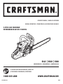 1
1
-
 2
2
-
 3
3
-
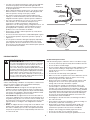 4
4
-
 5
5
-
 6
6
-
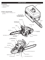 7
7
-
 8
8
-
 9
9
-
 10
10
-
 11
11
-
 12
12
-
 13
13
-
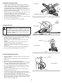 14
14
-
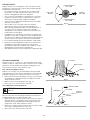 15
15
-
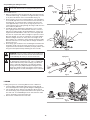 16
16
-
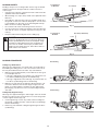 17
17
-
 18
18
-
 19
19
-
 20
20
-
 21
21
-
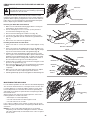 22
22
-
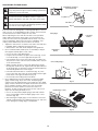 23
23
-
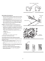 24
24
-
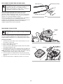 25
25
-
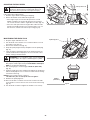 26
26
-
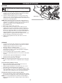 27
27
-
 28
28
-
 29
29
-
 30
30
-
 31
31
-
 32
32
-
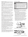 33
33
-
 34
34
-
 35
35
-
 36
36
-
 37
37
-
 38
38
-
 39
39
-
 40
40
-
 41
41
-
 42
42
-
 43
43
-
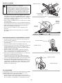 44
44
-
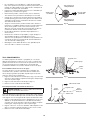 45
45
-
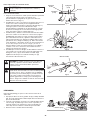 46
46
-
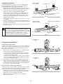 47
47
-
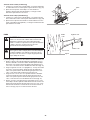 48
48
-
 49
49
-
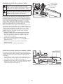 50
50
-
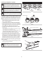 51
51
-
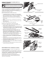 52
52
-
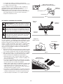 53
53
-
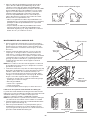 54
54
-
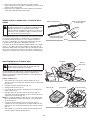 55
55
-
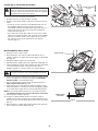 56
56
-
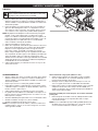 57
57
-
 58
58
-
 59
59
-
 60
60
-
 61
61
-
 62
62
-
 63
63
-
 64
64


Crafstman 41CY4218793 El manual del propietario
- Categoría
- Motosierras eléctricas
- Tipo
- El manual del propietario
- Este manual también es adecuado para
en otros idiomas
- English: Crafstman 41CY4218793 Owner's manual
Artículos relacionados
Otros documentos
-
MTD TB4218CC El manual del propietario
-
MTD TB4620CC El manual del propietario
-
-
Craftsman 46cc El manual del propietario
-
Black Max BM5020 El manual del propietario
-
-
Remington RM5118R El manual del propietario
-
Troy-Bilt 41AD25PS766 Manual de usuario
-
Cub Cadet CS511 Manual de usuario
-