Black Max BM5020 El manual del propietario
- Categoría
- Motosierras eléctricas
- Tipo
- El manual del propietario

OPERATOR’S MANUAL
MANUAL DEL OPERADOR
BM5020
20 in. 50cc Chain Saw
Motosierra de 50 cm (20 pulg.), 50 cc
ENGINE FAMILY: *HCPS.0505CA
FAMILIA DE MOTOR: *HCPS.0505CA
WARNING: To reduce the risk of injury, the user must
read and understand the operator’s manual before using this
product.
ADVERTENCIA: Para reducir el riesgo de lesiones,
el usuario debe leer y comprender el manual del operador antes
de usar este producto.
TABLE OF CONTENTS
General Safety Rules ............................................................2-3
Specific Safety Rules ............................................................3-4
Symbols ................................................................................5-6
Glossary of Terms ....................................................................7
Features ................................................................................8-9
Assembly ...............................................................................10
Operation ..........................................................................10-24
Maintenance .....................................................................24-36
Bar and Chain Combinations .................................................37
Troubleshooting ................................................................37-38
Parts Ordering/Service ............................................. Back Page
ÍNDICE DE CONTENIDO
Reglas de seguridad generales ...........................................2-3
Reglas de seguridad específicas .........................................4-5
Símbolos ..............................................................................6-7
Glosario de términos ............................................................... 8
Características ...................................................................9-10
Armado ................................................................................. 11
Funcionamiento ...............................................................11-26
Mantenimiento .................................................................26-39
Combinaciones de barra y cadena ....................................... 40
Corrección de problemas ................................................40-41
Pedidos de piezas/servicio ................................ Pág. posterior
SAVE THIS MANUAL FOR
FUTURE REFERENCE
GUARDE ESTE MANUAL
PARA FUTURAS CONSULTAS
NOTICE AVISO
Do not use E15 or E85 fuel in
this product. It is a violation of
federal law and will damage the
unit and void your warranty. Only use unleaded gasoline
containing up to 10% ethanol.
No utilice combustibles E15 o E85 con este producto. Esto
constituye una violación a la ley federal, dañará la unidad y
anulará la garantía. Utilice únicamente gasolina sin plomo
que contiene hasta 10% de etanol.
To register your Black Max product, please visit:
www.blackmaxtools.com
Para registrar su producto de Black Max, por favor visita:
www.blackmaxtools.com

Page 2 — English
WARNING:
Read and understand all instructions. Failure
to follow all instructions listed below, may result
in electric shock, fire and/or serious personal
injury.
READ ALL INSTRUCTIONS
Know your tool. Read the operator’s manual
carefully. Learn the saw’s applications and limi-
tations as well as the specific potential hazards
related to this tool.
■ Kickback may occur when the nose or tip of
the guide bar touches an object, or when the
wood closes in and pinches the saw chain in
the cut. Tip contact in some cases may cause a
lightning-fast reverse reaction, kicking the guide
bar up and back toward the operator. Pinching
the saw chain along the top of the guide bar
may push the guide bar rapidly back toward the
operator. Either of these reactions may cause you
to lose control of the saw, which could result in
serious personal injury. Do not rely exclusively
upon the safety devices built into the saw. As a
chain saw user, you should take several steps
to keep your cutting jobs free from accident or
injury.
• With a basic understanding of kickback,
you can reduce or eliminate the element of
surprise. Sudden surprise contributes to ac-
cidents.
• Keep a good firm grip on the saw with both
hands when the engine is running. Place your
right hand on the rear handle and your left
hand on the front handle with your thumbs
and fingers encircling the chain saw handles. A
firm grip together with a stiff left arm will help
you maintain control of the saw if kickback
occurs.
• Make sure that the area in which you are cut-
ting is free from obstructions. DO NOT let the
nose of the guide bar contact a log, branch,
fence, or any other obstruction that could be
hit while you are operating the saw.
• Cut at high engine speeds. Always cut with
the engine running at full speed. Fully squeeze
the throttle trigger and maintain a steady cut-
ting speed.
• Do not overreach or cut above chest height.
• Follow the manufacturer’s sharpening and
maintenance instructions for the saw chain.
• Only use replacement bars and chains speci-
fied by the manufacturer or the equivalent.
Do not operate a chain saw with one hand.
Serious injury to the operator, helpers, bystand-
ers, or any combination of these persons may
result from one-handed operation. A chain saw
is intended for two-handed use.
Do not operate a chain saw when you are
fatigued. Fatigue causes carelessness. Never
operate a chain saw when you are tired, upset,
or under the influence of medication, drugs, or
alcohol.
Stay alert – Watch what you are doing and use
common sense when operating a chain saw. A
moment of inattention while operating the chain
saw may result in death or serious personal
injury.
Chain saw work can be strenuous. If you have
a medical condition that may be aggravated or
a disability that may prevent you from safely
operating and controlling the chain saw, check
with your doctor before using the chain saw.
Use safety footwear. Wear snug-fitting clothing,
protective gloves, and eye, hearing, and head
protection devices.
Heavy protective clothing may increase
operator fatigue, which could lead to heat
stroke. During weather that is hot and humid,
heavy work should be scheduled for early morn-
ing or late afternoon hours when temperatures
are cooler.
Do not stand on any unstable surface while
using the chain saw, such as ladders, scaffolds,
trees, etc.
Use caution when handling fuel. Move the
chain saw at least 30 feet from the fueling point
before starting the engine.
Do not allow other persons to be near the
chain saw when starting or cutting with the
chain saw. Keep bystanders and animals out
of the work area.
Do not start cutting until you have a clear
work area, secure footing, and a planned retreat
path from the falling tree.
GENERAL SAFETY RULES

Page 3 — English
WARNING:
The warnings, labels, and instructions found
in this section of the operator’s manual are for
your safety. Failure to follow all instructions may
result in serious personal injury.
Do not cut vines and/or small underbrush (a
diameter of less than 3 in.).
Keep all parts of your body away from the
saw chain when the engine is running.
Always carry the chain saw with the engine
stopped and the brake engaged, the guide bar
and saw chain to the rear, and the muffler away
from your body. When transporting the chain
saw, use the appropriate guide bar scabbard.
Do not operate a chain saw that is damaged,
improperly adjusted, or not completely and se-
curely assembled. Be sure that the saw chain
stops moving when the throttle control trigger
is released.
■Shut off the engine before setting the chain
saw down. Do not leave the engine running
unattended. As an additional safety precaution,
apply the chain brake prior to setting down the
saw.
■Use extreme caution when cutting small-size
brush and saplings because slender material
may catch the saw chain and be whipped toward
you or pull you off balance.
■When cutting a limb that is under tension,
be alert for springback so that you will not be
struck when the tension in the wood fibers is
released.
■Keep the handles dry, clean, and free of oil or
fuel mixture.
Do not start or operate the engine in a con-
fined space, building, near open windows,
or in other unventilated space where dan-
gerous carbon monoxide fumes can collect.
Carbon monoxide, a colorless, odorless, and
extremely dangerous gas, can cause uncon-
sciousness or death.
■Do not operate a chain saw in a tree unless
you have been specifically trained to do so.
Do not cut from a ladder, rooftop, or other
unstable support; this is extremely dangerous.
All chain saw service, other than the items listed
in the instruction manual and all maintenance,
should be performed by competent chain saw
service personnel. (For example, if improper
tools are used to remove the flywheel or if an
improper tool is used to hold the flywheel in
order to remove the clutch, structural damage
to the flywheel could occur and subsequently
could cause the flywheel to burst.)
Always have a fire extinguisher available when
using chain saw.
Use only the replacement guide bars and low
kickback chains specified for the saw.
■Do not adapt the powerhead to a bow guide
or use it to power any attachments or devices
not listed for the saw.
■The gas powered saw is classified by CSA
Z62.1-15 as a Class 1C saw. It is intended for
infrequent use by homeowners, cottagers, and
campers, and for such general applications as
clearing, pruning, cutting firewood, etc. It is not
intended for prolonged use. Prolonged periods
of operation can cause circulatory problems in
the user’s hands due to vibration.
Save these instructions. Refer to them fre-
quently and use to instruct other users. If you loan
someone this tool, loan them these instructions
also.
Muffler surfaces are very hot during and after
operation of the chain saw; keep all body parts
away from the muffler. Serious burns may occur
if contact is made with the muffler.
■Always hold the chain saw with both hands
when the engine is running. Use a firm grip
with thumbs and fingers encircling the chain
saw handles.
GENERAL SAFETY RULES
SPECIFIC SAFETY RULES

Page 4 — English
■This product is intended for infrequent use
by homeowners and other occasional users
for general applications such as clearing, prun-
ing, cutting firewood, etc. It is not intended for
prolonged use. Prolonged periods of operation
can cause circulatory problems in the user’s
hands due to vibration. For such use, it may
be appropriate to use a product having an anti-
vibration feature.
REFUELING (DO NOT SMOKE!)
■To reduce the risk of fire and burn injury,
handle fuel with care. It is highly flammable.
■Mix and store fuel in a container approved for
gasoline.
■Mix fuel outdoors where there are no sparks
or flames.
■Select bare ground, stop the engine, and al-
low it to cool before refueling.
■Loosen the fuel cap slowly to release pressure
and to keep fuel from escaping around the cap.
■Tighten the fuel cap securely after refueling.
■Wipe spilled fuel from the unit. Move 30 feet
away from refueling site before starting engine.
Never attempt to burn off spilled fuel under
any circumstances.
KICKBACK
Kickback is a dangerous reaction that can
lead to serious injury. Do not rely only on the
safety devices provided with the saw. As a
chain saw user, you must take special safety
precautions to help keep your cutting jobs free
from accident or injury. See the General Safety
Rules and Operation sections of this manual
for added information on kickback and how to
avoid serious personal injury.
CAUTION: Do not use a replacement saw chain
unless it has been designated as meeting the
kickback performance requirements in ANSI/
OPEI B175.1-2012 on that specific power head,
or has been designated as low-kickback replace-
ment saw chain in accordance with ANSI/OPEI
B175.1-2012
■Never let anyone use the chain saw who
has not received adequate instructions in its
proper use. This applies to rentals as well as
privately owned saws.
■Before you start the engine, make sure the
saw chain is not contacting any object.
Wear snug-fitting clothing. Always wear heavy
long pants, boots, and gloves. Do not wear
jewelry, short pants, sandals, or go barefoot.
Do not wear loose fitting clothing, which could
be drawn into the engine or catch the chain or
underbrush. Wear overalls, jeans, or chaps made
of cut-resistant material or ones that contain
cut-resistant inserts. Secure hair so that it is
above shoulder level.
■Wear non-slip safety footwear and heavy-duty
gloves to improve your grip and to protect your
hands.
■Wear eye protection with side shields marked
to comply with ANSI Z87.1, along with hear-
ing and head protection, when operating this
equipment.
Keep bystanders and animals out of the work
area. Do not allow other persons to be nearby
during starting or cutting with the chain saw.
NOTE: The size of the work area depends on the
job being performed as well as the size tree or
workpiece involved. For example, felling a tree
requires a larger work area than making other
cuts (i.e., bucking cuts, etc.).
Keep SAFE-T-TIP anti-kickback nose guard
properly mounted on the guide bar to prevent
rotational kickback.
Follow the sharpening and maintenance in-
structions for the saw chain.
Never operate a chain saw that is damaged,
improperly adjusted, or is not completely and
securely assembled. Be sure that the saw chain
stops moving when the throttle control trigger is
released. If the saw chain moves at idle speed,
the carburetor may need adjusting. Refer to
Adjusting the Carburetor in the Maintenance
section of this manual. If the saw chain still moves
at idle speed after adjustment has been made,
contact a qualified service center for adjustment
and discontinue use until the repair is made.
SAVE THESE INSTRUCTIONS
SPECIFIC SAFETY RULES

Page 5 — English
The following signal words and meanings are intended to explain the levels of risk associated with
this product.
SYMBOL SIGNAL MEANING
DANGER:
Indicates a hazardous situation, which, if not avoided, will result
in death or serious injury.
WARNING:
Indicates a hazardous situation, which, if not avoided, could
result in death or serious injury.
CAUTION:
Indicates a hazardous situation, that, if not avoided, may result
in minor or moderate injury.
NOTICE:
(Without Safety Alert Symbol) Indicates information considered
important, but not related to a potential injury (e.g. messages
relating to property damage).
Some of the following symbols may be used on this tool. Please study them and learn their meaning.
Proper interpretation of these symbols will allow you to operate the tool better and safer.
SYMBOL NAME DESIGNATION/EXPLANATION
Safety Alert Indicates a potential personal injury hazard.
Read Operator’s Manual
To reduce the risk of injury, user must read and understand
operator’s manual before using this product.
Wear Eye, Hearing, and
Head Protection
Wear eye protection with side shields marked to comply
with ANSI Z87.1 as well as hearing and head protection
when operating this equipment.
Keep Tool Away from
Electrical Lines/Keep
Bystanders Away
DANGER! Risk of electrocution! Keep tool 50 feet away
from electrical lines. Keep all bystanders at least 50 ft.
away or twice the height of the largest trees in the felling
area when felling.
Safety Tip Nose Guard
The safety tip nose guard on the guide bar helps prevent
kickback.
Operate With Two Hands Hold and operate the saw properly with both hands.
One Handed Do not operate the saw using only one hand.
Bar Nose Contact
Avoid bar nose contact. Tip contact may cause the guide
bar to move suddenly upward and backward, which may
cause serious injury.
SYMBOLS

Page 6 — English
Some of the following symbols may be used on this tool. Please study them and learn their meaning.
Proper interpretation of these symbols will allow you to operate the tool better and safer.
SYMBOL NAME DESIGNATION/EXPLANATION
Kickback DANGER! BEWARE OF KICKBACK.
Hot Surface
To reduce the risk of injury or damage, avoid contact with
any hot surface.
Wear Gloves
Wear non-slip, heavy-duty protective gloves when
handling the chain saw.
Wear Safety Footwear Wear non-slip safety footwear when using this equipment.
No Smoking No smoking, sparks, or open flame.
Carbon Monoxide
Engines produce carbon monoxide which is an odorless,
deadly poison. Do not operate in an enclosed area.
Keep Bystanders Away Keep all bystanders and animals at least 50 ft. away.
Gasoline and
Lubricant
Use unleaded gasoline intended for motor vehicle use with
an octane rating of 87 [(R + M)/2] or higher. This product
is powered by a 2-cycle engine and requires pre-mixing
gasoline and 2-cycle lubricant.
SYMBOLS

Page 7 — English
Automatic Oiler System
Lubrication is provided by the automatic oiler sys-
tem. The oiler is driven by the sprocket and adds
lubrication only when the chain is moving.
Bucking
The process of cross cutting a felled tree or log
into lengths.
Chain Brake
A device used to stop the saw chain.
Chain Saw Powerhead
A chain saw without the saw chain and guide bar.
Clutch
A mechanism for connecting and disconnecting
a driven member to and from a rotating source of
power.
Drive Sprocket or Sprocket
The toothed part that drives the saw chain.
Felling
The process of cutting down a tree.
Felling Back Cut
The final cut in a tree felling operation made on
the opposite side of the tree from the notching
undercut.
Front Handle
The support handle located at or toward the front
of the chain saw. This handle is for the left hand.
Front Handle Guard
A structural barrier between the front handle of
a chain saw and the guide bar, typically located
close to the hand position on the front handle, and
sometimes employed as an activating lever for a
chain brake.
Guide Bar
A solid railed structure that supports and guides
the saw chain.
Kickback
The backward or upward motion, or both, of the
guide bar occurring when the saw chain near the
nose of the top area of the guide bar contacts any
object such as a log or branch, or when the wood
closes in and pinches the saw chain in the cut.
Kickback (Pinch)
The rapid pushback of the saw which can occur
when the wood closes in and pinches the moving
saw chain in the cut along the top of the guide bar.
Kickback (Rotational)
The rapid upward and backward motion of the
saw which can occur when the moving saw chain
near the upper portion of the tip of the guide bar
contacts an object, such as a log or branch.
Low-Kickback Chain
A low kickback saw chain is a chain that has met
the kickback performance requirements of ANSI/
OPEI B175.1-2012 when tested according to the
provisions specified in ANSI/OPEI B175.1-2012.
Normal Cutting Position
Those positions assumed in performing the buck-
ing and felling cuts.
Notching Undercut
A notch cut in a tree that directs the tree’s fall.
Rear Handle
The support handle located at or toward the rear
of the saw. It normally contains the throttle. This
handle is for the right hand.
Reduced Kickback Guide Bar
A guide bar which has been demonstrated to re-
duce kickback significantly.
Replacement Saw Chain
A chain that complies with the kickback perfor-
mance requirements of ANSI B175.1 when tested
with specific chain saws.
Safety Tip Anti-Kickback Nose Guard
An attachment that may be provided on the end
of the guide bar to prevent the chain at the end of
the guide bar from contacting the wood.
Saw Chain
A loop of chain having cutting teeth that cut the
wood, and that is driven by the sprocket and is
supported by the guide bar.
Springpole
A small tree (sapling) or limb that is bent or trapped
under tension. It may “spring back” rapidly when
cut, causing a dangerous situation.
GLOSSARY OF TERMS

Page 8 — English
PRODUCT SPECIFICATIONS
Bar length ................................................... 20 in.
Chain pitch ............................................. .325 in.
Chain gauge ........................................... .050 in.
Chain type ............................................ Standard
Drive sprocket ......................................... 7-tooth
Engine displacement ................................... 50cc
Chain drive links .............................................. 78
Idle engine speed ..........2,600-3,400/min. (RPM)
Fuel tank capacity .................................. 19.4 oz.
Chain lubricant tank capacity ................. 11.8 oz.
Fig. 1a
FRONT HAND GUARD/
CHAIN BRAKE
FRONT
HANDLE
AIR FILTER/
CYLINDER
COVER
TRIGGER
RELEASE
CHAIN OIL
CAP
SAFETY TIP
PRIMER
BULB
CHOKE
LEVER
BAR
MOUNTING
NUTS
MUFFLER
STARTER GRIP
AND ROPE
THROTTLE
TRIGGER
REAR
HANDLE
CHAIN TENSIONING
SCREW
CLUTCH COVER
FELLING
DIRECTION
SIGHTS
FEATURES

Page 9 — English
KNOW YOUR CHAIN SAW
See Figures 1a - 1b.
The safe use of this product requires an
understanding of the information on the product
and in this operator’s manual as well as a
knowledge of the project you are attempting.
Before use of this product, familiarize yourself
with all operating features and safety rules.
CHOKE LEVER
The choke lever opens and closes the choke valve
in the carburetor. Positions available include FULL
CHOKE and RUN.
FELLING DIRECTION SIGHTS
The felling direction sights helps you keep the saw
aligned properly during tree felling.
FRONT HAND GUARD / CHAIN BRAKE
The chain brake is designed to quickly stop the
chain from rotating. When the front hand guard/
chain brake is pushed toward the bar, the chain
should stop immediately. The chain brake does
not prevent kickback.
GUIDE BAR
The factory-equipped guide bar has a small ra-
dius tip that offers a somewhat lower kickback
potential.
LOW KICKBACK SAW CHAIN
The low kickback saw chain helps minimize the
force of a kickback reaction by preventing the
cutters from digging in too deeply at the kickback
zone.
PRIMER BULB
The primer bulb pumps fuel from the fuel tank to
the car buretor.
SAFETY TIP ANTI-KICKBACK NOSE GUARD
The safety tip Anti-Kickback Nose Guard is an
attachment provided on the end of the guide bar
to prevent the chain on the end of the guide bar
from contacting the wood.
THROTTLE TRIGGER
The throttle trigger is used for controlling chain
rotation.
Fig. 1b
REAR
HANDLE
THROTTLE
TRIGGER
FUEL CAP
STARTER/FAN
HOUSING
AIR FILTER/
CYLINDER
COVER
STARTER GRIP
AND ROPE
STOP
SWITCH
FELLING
DIRECTION
SIGHTS
FEATURES

Page 10 — English
WARNING:
Do not allow familiarity with this product to
make you careless. Remember that a careless
fraction of a second is sufficient to inflict seri-
ous injury.
WARNING:
Muffler surfaces are very hot during and after
operation of the chain saw; keep all body parts
away from the muffler. Serious burns could
occur if contact is made with the muffler.
DANGER:
Never cut near power lines, electric cords, or
other electric sources. If bar and chain jams
on any electrical cord or line, DO NOT TOUCH
THE BAR OR CHAIN! THEY CAN BECOME
ELECTRICALLY LIVE AND VERY DANGEROUS.
Continue to hold the chain saw by the insulated
rear handle or lay it down and away from you in
a safe manner. Disconnect the electrical service
to the damaged line or cord before attempting
to free the bar and chain from the line or cord.
Contact with the bar, chain, other conductive
parts of the chain saw, or live electric cords or
lines will result in death by electrocution, electric
shock, or serious personal injury.
PACKING LIST
Chain Saw
Scabbard
Combination Wrench
2-Cycle Engine Lubricant
Carrying Case
Operator’s Manual
WARNING:
If any parts are damaged or missing do not
operate this product until the parts are replaced.
Use of this product with damaged or missing
parts could result in serious personal injury.
WARNING:
Do not attempt to modify this product or create
accessories not recommended for use with this
product. Any such alteration or modification is
misuse and could result in a hazardous condi-
tion leading to possible serious personal injury.
NOTE: The chain saw has been fully factory
tested. It is normal to find some slight lubricant
residue on the saw. Read and remove all hang tags
and store with the Operator’s Manual.
UNPACKING
This product has been shipped completely as-
sembled.
Carefully remove the product and any acces-
sories from the box. Make sure that all items
listed in the packing list are included.
WARNING:
Do not use this product if it is not completely
assembled or if any parts appear to be missing
or damaged. Use of a product that is not prop-
erly and completely assembled could result in
serious personal injury.
Inspect the product carefully to make sure no
breakage or damage occurred during shipping.
Do not discard the packing material until you
have carefully inspected and satisfactorily oper-
ated the product.
If any parts are damaged or missing, please call
1-800-726-5760 for assistance.
ASSEMBLY
OPERATION

Page 11 — English
APPLICATIONS
You may use this product for the purposes listed
below:
Basic limbing, felling, and woodcutting
FUEL AND REFUELING
HANDLING THE FUEL SAFELY
WARNING:
Check for fuel leaks. A leaking fuel cap is a fire
hazard and must be replaced immediately. If
you find any leaks, correct the problem before
using the product. Failure to do so could result
in a fire that could cause serious personal injury.
Always handle fuel with care; it is highly
flammable.
Always refuel outdoors and do not inhale fuel
vapors.
Do not let gasoline or lubricant come in contact
with skin.
Keep gasoline and lubricant away from the eyes.
If gasoline or lubricant comes in contact with
the eyes, wash them immediately with clean
water. If irritation is still present, see a doctor
immediately.
Clean up spilled fuel immediately.
Refer to Refueling in the Specific Safety Rules
section of this manual for additional safety infor-
mation.
ETHANOL-BLENDED FUELS
NOTICE:
Do not use E15 or E85 fuel in this product. It
is a violation of federal law and will damage
the unit and void your warranty. Only use
unleaded gasoline containing up to 10%
ethanol.
NOTE: To improve performance when using
ethanol-blended fuels, we recommend the use of
Ethanol Shield 2-cycle lubricant.
WARNING:
Always wear eye protection with side shields
marked to comply with ANSI Z87.1, along with
hearing and head protection. Failure to do so
could result in objects being thrown into your
eyes and other possible serious injuries.
WARNING:
Do not use any attachments or accessories
not recommended by the manufacturer of this
product. The use of attachments or accessories
not recommended can result in serious personal
injury.
WARNING:
This product is equipped with a spark arrestor
that has been evaluated by the USDA Forest
Service; however, product users must comply
with Federal, State, and local fire prevention
regulations. Check with appropriate authori-
ties. Contact customer service or a qualified
service center to purchase a replacement spark
arrestor.
WARNING:
Never fell a tree or cut a log or limb that has a
diameter greater that the length of the guide
bar. Only properly trained professionals should
perform these cuts. Performing these types of
cuts can cause an accident and result in death
or serious personal injury.
NOTICE:
Before each use, inspect the entire product
for damaged, missing, or loose parts such as
screws, nuts, bolts, caps, etc. Tighten securely
all fasteners and caps and do not operate this
product until all missing or damaged parts are
replaced. Please contact customer service or a
qualified service center for assistance.
OPERATION

Page 12 — English
MIXING THE FUEL
This product is powered by a 2-cycle engine and
requires pre-mixing gasoline and 2-cycle lubricant.
Pre-mix unleaded gasoline and 2-cycle engine
lubricant in a clean container approved for gaso-
line. DO NOT mix quantities larger than usable in
a 30-day period.
Recommended fuel: This engine is certified to
operate on unleaded gasoline intended for auto-
motive use.
NOTE: We recommend you use Ethanol Shield
2-cycle lubricant or an equivalent high-quality
synthetic 2-cycle lubricant in this product. Mix at
2.6 oz. per gallon (US).
Do not use automotive lubricant or 2-cycle out-
board lubricant.
HIGH QUALITY 2-CYCLE ENGINE
LUBRICANT (50:1)
GASOLINE LUBRICANT
1 Gallon (US) 2.6 oz.
1 Liter 20 cc (20 ml)
FILLING THE FUEL TANK
See Figure 2.
WARNING:
Gasoline and its vapors are highly flammable
and explosive. To prevent serious personal
injury and property damage, handle it with care.
Keep away from ignition sources and open
flames, handle outdoors only, do not smoke,
and wipe up spills immediately.
Clean the surface around the fuel cap to prevent
contamination.
Loosen the fuel cap slowly, by turning counter-
clockwise.
Carefully pour the fuel mixture into the tank.
Avoid spillage.
Prior to replacing the fuel cap, clean and inspect
the o-ring.
Immediately replace the fuel cap and hand
tighten, by turning clockwise. Wipe up any fuel
spillage.
Fig. 2
Move at least 30 ft. away from refueling area
before starting the product.
NOTE: It is normal for the engine to emit smoke
during and after the first use.
WARNING:
Always shut off engine before fueling. Never
remove fuel cap or add fuel to a machine with
a running or hot engine. Make sure unit is sit-
ting on a flat, level surface and only add fuel
outdoors. If the engine is hot, allow to cool for
at least five minutes before adding fuel. Imme-
diately replace fuel cap after fueling and tighten
securely. Move at least 30 ft. from refueling site
before starting the engine. Do not smoke and
stay away from open flames and sparks. Failure
to follow these instructions can result in a fire
and possible serious personal injury.
ADDING BAR AND CHAIN LUBRICANT
See Figure 3.
Use a bar and chain lubricant designed for lubri-
cating chain saw chains. They are formulated to
extend bar and chain life by protecting against
wear and reducing friction and heat. Chain saw
should use approximately one tank of lubricant
per tank of fuel.
NOTE: Do not use dirty, used, or otherwise con-
taminated lubricants. Damage will occur to the oil
pump, bar, or chain.
Carefully pour the bar and chain lubricant into
the oil tank.
Fill the oil tank every time you fuel the engine.
OPERATION

Page 13 — English
Fig. 3
OPERATING THE CHAIN BRAKE
See Figures 4 - 5.
Check the operating condition of the chain brake
prior to each use.
Engage the chain brake by rotating your left
hand around the front handle, allowing the back
of your hand to push the chain brake lever/hand
guard toward the bar while the chain is rotating
rapidly. Be sure to maintain both hands on the
saw handles at all times.
Reset the chain brake back into the RUN PO-
SITION by grasping the top of the chain brake
lever/hand guard and pulling toward the front
handle until you hear a click.
WARNING:
If the chain brake does not stop the chain
immediately, or if the chain brake will not stay
in the run position without assistance, take the
saw to an authorized service center for repair
prior to use.
NOTICE:
Before each use, check to make sure that the
chain is properly tensioned. A cold chain is cor-
rectly tensioned when there is no slack on the
underside of the guide bar, the chain is snug,
and it can be turned by hand without binding.
During normal saw operation, the temperature
of the chain increases. The drive links of a cor-
rectly tensioned warm chain will hang approxi-
mately .050 in. out of the bar groove.
See the Adjusting the Chain Tension instruc-
tions in the Maintenance section of this manual
to properly adjust the chain tension.
Fig. 4
Fig. 5
BRAKE
POSITION
RUN
POSITION
OPERATION

Page 14 — English
Fig. 8
Fig. 9
CHOKE
LEVER
PRIMER BULB
10X
RUN
POSITION
Fig. 7
Fig. 6
STARTER GRIP
AND ROPE
STARTING THE ENGINE
See Figures 6 - 10.
Starting the product differs depending on whether
the engine is cold or warm.
WARNING:
Keep your body to the left of the chain line.
Never straddle the saw or chain, or lean over
past the chain line.
Place the chain saw on level ground and en-
sure that no objects or obstructions are in the
immediate vicinity that could come in contact
with the bar and chain.
Hold the front handle firmly with your left hand
and put your right foot onto the base of the rear
handle.
To start a cold engine:
Make sure the chain brake is in the run position
by pulling back on the lever/hand guard.
Fully press and release the primer bulb 10 times.
Pull choke lever all the way out to FULL CHOKE
position.
When the temperature is above 50°F, pull the
starter grip and rope until the engine attempts
to start, but no more than 3 times. When the
temperature is below 50°F, pull the starter grip
and rope until the engine attempts to start, but
no more than 5 times.
Push choke lever in to RUN position.
Pull starter grip and rope until engine runs.
NOTE: Allow the saw to run in this position 15–30
seconds, depending upon the
temperature.
Depress the trigger release and squeeze and
release the throttle trigger to return the engine to
idle after a total run time of at least 30 seconds.
NOTICE:
Failure to release partial throttle when chain
brake lever is in the brake position will result in
serious damage to the unit. Never squeeze and
hold the throttle trigger while the chain brake is
in the brake position.
OPERATION

Page 15 — English
BRAKE
POSITION
Fig. 12
Fig. 11
STOP
SWITCH
Fig. 10
THROTTLE
TRIGGER
TRIGGER
RELEASE
To Start a Warm Engine:
Make sure the chain brake is in the run position
by pulling back on the lever/hand guard.
Pull choke lever out to FULL CHOKE position
then push immediately back to RUN position
to set fast idle.
Pull starter grip and rope until engine runs, but
no more than 5 times. If engine does not start
after 5 pulls, use cold engine starting procedure.
Squeeze and release the throttle trigger to return
the engine to idle.
STOPPING THE ENGINE
See Figures 11 - 12.
Release the throttle trigger and let the engine re-
turn to idle. To stop the engine, fully press the stop
switch. Do not put the chain saw on the ground
when the chain is still moving. For additional safety,
set the chain brake when the saw is not in use.
In the event that the stop switch will not stop the
saw, pull the choke lever out to the fully extended
position (FULL CHOKE ) and engage chain brake
to stop the engine. If the stop switch will not stop
the saw when pressed, have the stop switch re-
paired before using the chain saw again to prevent
unsafe conditions or serious injury.
NOTE: When you are finished using the saw,
always relieve tank pressure by loosening, then
retightening, the chain oil and fuel caps. Allow the
engine to cool before storing.
OPERATION

Page 16 — English
Fig. 13
IDLE SPEED
SCREW “T”
ADJUSTING IDLE SPEED
See Figure 13.
WARNING:
The chain will move around the guide bar when
adjusting the idle speed. Wear all protective
clothing and keep all bystanders, children, and
pets at least 50 ft. away. Make adjustments
with the unit supported on a stable surface so
that the chain/guide bar does not contact the
ground or any object. Keep all parts of your
body away from the chain/guide bar and muf-
fler. Failure to follow these instructions could
result in serious personal injury.
If the engine starts, runs, and accelerates, but will
not idle, turn the idle speed screw “T” clockwise
to increase idle speed.
If the chain turns at idle, turn the idle speed screw
“T” counterclockwise to reduce the idle RPM
and stop the chain movement. If the saw chain
still moves at idle speed, contact an authorized
service center for adjustment and discontinue
use until the repair is made.
WARNING:
THE SAW CHAIN SHOULD NEVER TURN AT
IDLE. Turn the idle speed screw “T” counter-
clockwise to reduce the idle RPM and stop the
chain, or contact an authorized service center
for adjustment and discontinue use until the
repair is made. Serious personal injury could
result from the saw chain turning at idle.
PULL AND PUSH
See Figure 14.
The reaction force of the saw is always opposite to
the direction the chain is moving. Thus, the opera-
tor must be ready to control the PULL when cutting
on the bottom edge of the bar and the PUSH when
cutting along the top edge.
NOTE: The chain saw has been fully factory
tested. It is normal to find some slight oil residue
on the saw.
Fig. 14
PULL
PUSH
OPERATION

Page 17 — English
WARNING:
KICKBACK occurs when the moving chain
contacts an object at the upper portion of the
tip of the guide bar or when the wood closes in
and pinches the saw chain in the cut. Contact
at the upper portion of the tip of the guide bar
can cause the chain to dig into the object and
stop the chain for an instant. The result is a
lightning-fast reverse reaction which kicks the
guide bar up and back toward the operator. If
the saw chain is pinched along the top of the
guide bar, the guide bar can be driven rapidly
back toward the operator. Either of these reac-
tions can cause loss of saw control, which can
result in serious injury.
Do not rely exclusively upon the safety devices
built into the saw. As a chain saw user, you
should take steps to keep your cutting jobs
free from accident or injury. See General Safety
Rules for more details.
KICKBACK PRECAUTIONS
See Figures 15 - 16.
Rotational kickback occurs when the moving chain
contacts an object at the Kickback Danger Zone of
the guide bar. The result is a lightning-fast reverse
reaction, which kicks the guide bar up and back
towards the operator. This reaction can cause loss
of control, which can result in serious injury.
PREPARING FOR CUTTING
PROPER GRIP ON HANDLES
See Figure 17.
See General Safety Rules for appropriate safety
equipment.
Wear non-slip gloves for maximum grip and
protection.
Hold the saw firmly with both hands. Always
keep your left hand on the front handle and your
right hand on the rear handle so that your body
is to the left of the chain line.
ROTATIONAL
KICKBACK
Fig. 16
KICKBACK
DANGER ZONE
Fig. 15
PROPER GRIP IMPROPER GRIP
Fig. 17
PROPER HAND
GRIP POSITION
OPERATION

Page 18 — English
WARNING:
Never use a left-handed (cross-handed) grip or
any stance that would place your body or arm
across the chain line. Improper operation of the
chain saw could result in serious personal injury.
WARNING:
DO NOT operate the throttle trigger with your
left hand and hold the front handle with your
right hand. Never allow any part of your body
to be in the chain line while operating a saw.
Improper operation of the chain saw could result
in serious personal injury.
CHAIN LINE
Maintain a proper grip on the saw whenever the
engine is running. The fingers should encircle
the handle and the thumb is wrapped under the
handlebar. This grip is least likely to be broken
by a kickback or other sudden reaction of the
saw. Any grip in which the thumb and fingers
are on the same side of the handle is dangerous
because a slight kick of the saw can cause loss
of control.
PROPER CUTTING STANCE
See Figure 18.
WARNING:
Alway use the proper cutting stance described
in this section. Never kneel when using the
chain saw except when felling a tree as shown
in figure 23b. Kneeling could result in loss of
stability and control of the saw resulting in seri-
ous personal injury.
Balance your weight with both feet on solid
ground.
Fig. 18
STRAIGHT
ARM
CHAIN LINE
THUMB ON
UNDERSIDE OF
HANDLE BAR
Fig. 19
Keep left arm with elbow locked in a “straight
arm” position to withstand any kickback force.
Keep your body to the left of the chain line.
Keep your thumb on underside of handlebar.
WORK AREA PRECAUTIONS
See Figure 19.
Cut only wood or materials made from wood;
no sheet metal, no plastics, no masonry, no
non-wood building materials.
■Never allow children to operate the saw. Allow
no person to use this chain saw who has not
read this operator’s manual or received adequate
instructions for the safe and proper use of this
chain saw.
■Keep everyone – helpers, bystanders, children,
and animals, a safe distance from the cutting
area. During felling operations, the safe dis-
tance should be a least twice the height of the
largest trees in the felling area. During bucking
OPERATION

Page 19 — English
operations, keep a minimum distance of 15 feet
between workers.
■Always cut with both feet on solid ground to
prevent being pulled off balance.
■Do not cut above chest height as a saw held
higher is difficult to control against kickback
forces.
■Do not fell trees near electrical wires or build-
ings. Leave this operation for professionals.
■Cut only when visibility and light are adequate
for you to see clearly.
BASIC OPERATING/CUTTING PROCEDURES
Practice cutting a few small logs using the follow-
ing technique to get the “feel” of using the saw
before you begin a major sawing operation.
Take the proper stance in front of the wood with
the saw idling.
Accelerate the engine to full throttle just before
entering the cut by squeezing the throttle trigger.
Begin cutting with the saw against the log.
Keep the engine at full throttle the entire time
you are cutting.
Allow the chain to cut for you; exert only light
downward pressure. Forcing the cut could result
in damage to the bar, chain, or engine.
Release the throttle trigger as soon as the cut is
completed allowing the engine to idle. Running
the saw at full throttle without a cutting load can
result in unnecessary wear to the chain, bar, and
engine.
Do not put pressure on the saw at the end of
the cut.
FELLING TREES
HAZARDOUS CONDITIONS
See Figures 20 - 23.
WARNING:
Do not fell trees during periods of high wind or
heavy precipitation. Wait until the hazardous
weather has ended.
HINGE
2 IN. (50 MM) OR 1/10 DIA
NOTCH -
APPROX. 1/3
DIAMETER OF
TRUNK
BACK CUT
2 IN. (50 MM)
Fig. 20
Fig. 21
45°
45°
PLANNED LINE
OF FALL
RETREAT PATH
RETREAT PATH
HINGE
BACK CUT
Fig. 22
OPERATION

Page 20 — English
WARNING:
Closely check for broken or dead branches,
which could fall while cutting and do not cut
near buildings or electrical wires if you do not
know the direction of tree fall. Do not cut at
night or during bad weather conditions, such as
rain, snow, or strong winds, which can reduce
visibility and control of the chain saw. If the tree
you are felling makes contact with any utility
line, you should discontinue use of the chain
saw and immediately notify the utility company.
Failure to follow these instructions could result
in death or serious personal injury.
When felling a tree, it is very important that you
closely follow these warnings and instructions to
prevent possible death or serious personal injury.
■Do not cut down trees having an extreme lean
or large trees with rotten limbs, loose bark,
or hollow trunks. Have these trees pushed or
dragged down with heavy equipment, then cut
them up.
■Do not cut trees near electrical wires or buildings.
■Check the tree for damaged or dead branches
that could fall and hit you during felling.
■Periodically glance at the top of the tree during
the backcut to assure the tree is going to fall in
the desired direction.
If the tree starts to fall in the wrong direction,
or if the saw gets caught or hung up during the
fall, leave the saw and save yourself!
Felling a tree – When bucking and felling op-
erations are being performed by two or more
persons, at the same time, the felling operation
should be separated from the bucking operation
by a distance of at least twice the height of the
tree being felled. Trees should not be felled in a
manner that would endanger any person, strike
any utility line or cause any property damage.
If the tree does make contact with any util-
ity line, the utility company should be notified
immediately.
Before any cuts are started, pick your escape
route (or routes in case the intended route is
blocked); clear the immediate area around the
tree and make sure there are no obstructions
in your planned path of retreat. Clear paths of
WEDGE
Fig. 23b
FELLING
DIRECTION
SIGHTS
PLANNED
LINE OF
FALL
TREE
Fig. 23a
safe retreat should extend back and diagonally
(45°) to the rear of the planned line of fall. When
the tree begins to fall, you should retreat away
from the direction of fall along a retreat path and
at least 20 feet away from the trunk in case it
kicks back over the stump. See Figure 20.
Before felling is started, consider the force and
direction of the wind, the lean and balance of
the tree, and the location of large limbs. These
things influence the direction in which the tree
will fall. Do not try to fell a tree along a line dif-
ferent from its natural line of fall.
OPERATION

Page 21 — English
The chain saw operator should keep on the
uphill side of the terrain as the tree is likely to
roll or slide downhill after it is felled.
Remove dirt, stones, loose bark, nails, staples,
and wire from the tree where felling cuts are to
be made.
NOTE: Before every cut, make sure the felling
sights on the saw housing are aligned with the
direction path for the tree to fall. Figure 23a shows
how the felling direction sights are used when
making the back cut.
Notched Undercut. Cut a notch about 1/3 the
diameter of the tree as shown in figure 21. Make
the cuts of the notch so they intersect at a right
angle to the line of fall. This notch should be
cleaned out to leave a straight line. To keep the
weight of the wood off the saw, always make
the lower cut of the notch before the upper cut.
See Figure 21.
Felling Backcut. The backcut is always made
level and horizontal, and at a minimum of 2 in.
above the horizontal cut of the notch. See Fig-
ures 21 - 22.
Never cut through to the notch. Always leave a
band of wood between the notch and backcut
(approximately 2 in. or 1/10 the diameter of the
tree). This is called “hinge” or “hingewood.” It
controls the fall of the tree and prevents slip-
ping or twisting or shoot-back of the tree off the
stump. See Figures 21 - 22.
On large diameter trees, stop the back cut before
it is deep enough for the tree to either fall or settle
back on the stump. Then insert soft wooden or
plastic wedges into the cut so they do not touch
the chain. The wedges can be driven in, little by
little, to help jack the tree over. See Figure 23b.
NOTE: When bucking or felling with a wedge,
it may be necessary to remove the safety tip
anti-kickback nose guard to allow the bar to be
drawn through the cut. After the cut is complete,
the tip should be reinstalled immediately.
As tree starts to fall, stop the chain saw and put
it down immediately. Retreat along the cleared
path, but watch the action in case something
falls your way. Be alert for overhead limbs or
branches that may fall and watch your footing.
KICKBACK
Fig. 24
WARNING:
Never cut through to the notch when making a
backcut. The hinge controls the fall of the tree,
this is the section of wood between the notch
and backcut.
BUCKING
See Figure 24.
Bucking is the term used for cutting a fallen tree
to the desired log length.
Cut only one log at a time.
Support small logs on a saw horse or another
log while bucking.
Keep a clear cutting area. Make sure that no
objects can contact the guide bar nose and
chain during cutting, this can cause kickback.
To avoid the danger, keep the safety tip anti-
kickback device attached while cutting. Refer to
Kickback in the Specific Safety Rules section
of this manual for more information.
■When bucking on a slope, always stand on the
uphill side of the log. To maintain complete con-
trol of the chain saw when cutting through the
log, release the cutting pressure near the end of
the cut without relaxing your grip on the chain
saw handles. Do not let the chain contact the
ground. After completing the cut, wait for the
saw chain to stop before you move the chain
saw. Always stop the motor before moving from
tree to tree.
OPERATION

Page 22 — English
BUCKING WITH A WEDGE
See Figure 25.
If the wood diameter is large enough for you to
insert a soft bucking wedge without touching the
chain, you should use the wedge to hold the cut
open to prevent pinching.
NOTE: When bucking or felling with a wedge, you
may need to remove the safety tip anti-kickback
device to allow the bar to be drawn through the
cut. After you complete the cut, reinstall the tip.
BUCKING LOGS UNDER STRESS
See Figure 26.
Make the first bucking cut 1/3 of the way through
the log and finish with a 2/3 cut on the opposite
side. As you cut the log, it will tend to bend. The
saw can become pinched or hung in the log if you
make the first cut deeper than 1/3 of the diameter
of the log.
Give special attention to logs under stress to pre-
vent the bar and chain from pinching.
OVERBUCKING
See Figure 27.
Begin on the top side of the log with the bottom
of the saw against the log; exert light pressure
downward. Note that the saw will tend to pull
away from you.
UNDERBUCKING
See Figure 28.
Begin on the under side of the log with the top
of the saw against the log; exert light pressure
upward. During underbucking, the saw will tend
to push back at you. Be prepared for this reaction
and hold the saw firmly to maintain control.
OVERBUCKING
Fig. 27
LOAD
FINISHING CUT
1ST CUT 1/3 DIA
LOG SUPPORTED AT ONE END
LOG SUPPORTED AT BOTH ENDS
FINISHING CUT
1ST CUT 1/3 DIA
LOAD
Fig. 26
Fig. 28
UNDERBUCKING
WEDGE
Fig. 25
OPERATION

Page 23 — English
LIMBING
See Figure 29.
WARNING:
Never climb into a tree to limb or prune. Do not
stand on ladders, platforms, a log, or in any
position which can cause you to lose your bal-
ance or control of the saw, which could result
in death or other serious personal injury.
Limbing is removing branches from a fallen tree.
Work slowly, keeping both hands on the chain
saw with a firm grip. Always make sure your
footing is secure and your weight is distributed
evenly on both feet.
Leave the larger support limbs under the tree
to keep the tree off the ground while cutting.
Limbs should be cut one at a time. Remove the
cut limbs from the work area often to help keep
the work area clean and safe.
Branches under tension should be cut from the
bottom up to avoid binding the chain saw.
Keep the tree between you and the chain saw
while limbing. Cut from the side of the tree op-
posite the branch you are cutting.
PRUNING
See Figure 30.
Pruning is trimming limbs from a live tree.
Work slowly, keeping both hands on the chain
saw with a firm grip. Always make sure your
footing is secure and your weight is distributed
evenly on both feet.
Do not cut from a ladder, this is extremely dan-
gerous. Leave this operation for professionals.
Do not cut above chest height as a saw held
higher is difficult to control against kickback.
When pruning trees it is important not to make
the finishing cut next to the main limb or trunk
until you have cut off the limb further out to
reduce the weight. This prevents stripping the
bark from the main member.
FINISHING CUT
FIRST CUT
1/3 DIAMETER
SECOND CUT
LOAD
Fig. 29
Fig. 30
CUT LIMBS ONE AT A TIME AND LEAVE SUPPORT
LIMBS UNDER TREE UNTIL LOG IS CUT
Underbuck the branch 1/3 through for your first
cut.
Your second cut should overbuck to drop the
branch off.
Now make your finishing cut smoothly and neatly
against the main member so the bark will grow
back to seal the wound.
WARNING:
If the limbs to be pruned are above chest height,
hire a professional to perform the pruning.
Failure to do so could result in death or serious
personal injury.
OPERATION

Page 24 — English
WARNING:
Always wear eye protection with side shields
marked to comply with ANSI Z87.1, along with
hearing and head protection. Failure to do so
could result in objects being thrown into your
eyes and other possible serious injuries.
WARNING:
When servicing, use only identical replacement
parts. Use of any other parts could create a
hazard or cause product damage.
NOTICE:
Periodically inspect the entire product for dam-
aged, missing, or loose parts such as screws,
nuts, bolts, caps, etc. Tighten securely all fas-
teners and caps and do not operate this product
until all missing or damaged parts are replaced.
Please contact customer service or a qualified
service center for assistance.
Normal maintenance, replacement or repair of
emission control devices and systems may be
performed by any qualified repair establishment
or individual with original or equivalent parts.
Warranty and recall repairs must be performed
by an authorized service center; please contact
customer service for assistance.
WARNING:
Before inspecting, cleaning, or servicing the
machine, shut off engine, wait for all moving
parts to stop, and disconnect spark plug wire
and move it away from spark plug. Failure to
follow these instructions can result in serious
personal injury or property damage.
WARNING:
Muffler surfaces are very hot during and after
operation of the chain saw; keep all body parts
away from the muffler. Serious burns could
occur if contact is made with the muffler.
CUTTING SPRINGPOLES
See Figure 31.
A springpole is any log, branch, rooted stump, or
sapling which is bent under tension by other wood
so that it springs back if the wood holding it is cut
or removed. On a fallen tree, a rooted stump has
a high potential of springing back to the upright
position during the bucking cut to separate the log
from the stump. Watch out for springpoles — they
are dangerous.
WARNING:
Springpoles are dangerous and could strike the
operator, causing the operator to lose control
of the chain saw. This could result in severe or
fatal injury to the operator.
SPRINGPOLE
Fig. 31
OPERATION
MAINTENANCE

Page 25 — English
GENERAL MAINTENANCE
Avoid using solvents when cleaning plastic parts.
Most plastics are susceptible to damage from vari-
ous types of commercial solvents and may be dam-
aged by their use. Use clean cloths to remove dirt,
dust, lubricant, grease, etc.
WARNING:
Do not at any time let brake fluids, gasoline,
petroleum-based products, penetrating oils, etc.,
come in contact with plastic parts. Chemicals can
damage, weaken or destroy plastic which may
result in serious personal injury.
LUBRICATION
All of the bearings in this product are lubricated with
a sufficient amount of high grade lubricant for the
life of the unit under normal operating conditions.
Therefore, no further lubrication is required.
REPLACING THE GUIDE BAR AND CHAIN
See Figures 32 - 41.
DANGER:
Never start the engine before installing the guide
bar, chain, clutch cover, and clutch drum. Without
all these parts in place, the clutch can fly off or
explode, exposing the user to possible serious
injury.
WARNING:
To avoid serious personal injury, read and under-
stand all the safety instructions in this section.
Stop the engine and disconnect the spark plug
wire before you work on the saw.
Make sure the chain brake is not set by pulling the
chain brake lever/hand guard towards the front
handle to the RUN POSITION.
NOTE: When replacing the guide bar and chain,
always use the specified bar and chain listed in the
Bar and Chain Combinations section later in this
manual.
Wear gloves when handling the chain and bar.
These components are sharp and may contain
burrs.
Fig. 32
Fig. 33
Fig. 34
Remove the bar mounting nuts using the combina-
tion wrench provided or a 13 mm socket wrench.
Remove the clutch cover.
Remove the bar and chain from the mounting
surface.
Remove the old chain from the bar.
Lay out the new saw chain in a loop and straighten
any kinks. The cutters should face in the direction
RUN
POSITION
BAR MOUNTING NUTS
COMBINATION
WRENCH
CLUTCH
COVER
BAR MOUNTING
NUTS
MAINTENANCE

Page 26 — English
of chain rotation. If they face backwards, turn the
loop over.
Place the chain drive links into the bar groove as
shown.
Position the chain so there is a loop at the back
of the bar.
Hold the chain in position on the bar and place
the loop around the sprocket.
Fit the bar flush against the mounting surface so
that the bar studs are in the long slot of the bar.
Replace the clutch cover ensuring that the adjust-
ing pin in the clutch cover is in the bar tension-
ing pin hole and that both bar studs are in their
respective holes in the clutch cover.
BAR
GROOVE
CHAIN DRIVE
LINKS
Fig. 36
CUTTERS
CHAIN ROTATION
CHAIN DRIVE LINKS
Fig. 35
Fig. 38
Fig. 37
ADJUSTING
PIN
BAR STUD HOLES
CLUTCH
COVER
SPROCKET
BAR
MOUNTING
NUTS
CHAIN
TENSIONING
SCREW
MAINTENANCE

Page 27 — English
NOTE: The adjusting pin may need to be slightly
repositioned with the chain tensioning screw so
that it is aligned with the position of the bar chain
tensioning pin hole.
Replace and fingertighten the bar mounting nuts.
The bar must be free to move for tension adjust-
ment.
Remove all slack from the chain by turning the
chain tensioning screw clockwise until the chain
seats snugly against the bar with the drive links
in the bar groove.
Lift the tip of the guide bar up to check for sag.
Release the tip of the guide bar and turn the chain
tensioning screw 1/2 turn clockwise. Repeat this
process until sag does not exist.
Hold the tip of the guide bar up and tighten the
bar mounting nuts securely.
The chain is correctly tensioned when there is no
sag on the underside of the guide bar, the chain is
snug, but it can be turned by hand without binding.
Ensure that the chain brake is not set.
NOTE: If chain is too tight, it will not rotate. Loosen
the bar nuts slightly and turn the tension adjuster 1/4
turn counterclockwise. Lift the tip of the guide bar
up and retighten the bar nuts securely. Ensure that
the chain will rotate without binding.
ADJUSTING THE CHAIN TENSION
See Figures 42 - 44.
WARNING:
Shut off engine, wait for all moving parts to stop,
and disconnect spark plug wire and move it away
from spark plug. Never touch or adjust the chain
while the engine is running. The saw chain is
very sharp. Always wear protective gloves when
performing maintenance on the chain. Failure
to follow these instructions can result in serious
personal injury.
Proper chain tension is critical to the performance
of your chain saw. Always check chain tension be-
fore using the saw and periodically until the work is
complete.
A cold chain is correctly tensioned when there is no
slack on the underside of the guide bar. The chain
should be snug, but still able to be turned by hand
without binding.
A warm chain is correctly tensioned when the flats
on the tie straps hang approximately .050 inches
out of the bar groove. The tip of the combination
wrench provided is approximately this size and can
be used to help determine if a warm chain is cor-
rectly tensioned.
If adjustment is needed:
Stop the engine and make sure the chain brake
is not set by pulling the chain brake lever/hand
guard toward the front handle to the run position.
Loosen the bar mounting nuts to finger tight.
Raise the tip of the guide bar and continue to hold
up until the end of this procedure.
Turn the chain tensioning screw clockwise until
the flats on the tie straps of the chain contact the
Fig. 39
Fig. 40
Fig. 41
MAINTENANCE

Page 28 — English
bar, making sure the drive links are seated inside
the bar groove.
Retighten the bar mounting nuts securely.
Release the tip of the guide bar and verify the chain
is now correctly tensioned using the guidelines
above.
NOTE: If the chain is too tight and will not rotate,
loosen the bar nuts slightly, then turn the chain
tensioning screw 1/4 turn counterclockwise. Lift
up the tip of the guide bar, retighten the bar nuts
securely, then verify the chain will now rotate
without binding.
NOTE: New chains tend to stretch; check the chain
tension frequently and adjust as needed.
NOTICE:
A chain tensioned while warm may be too tight
upon cooling. Check the “cold tension” before
next use.
CHAIN MAINTENANCE
See Figures 45 - 46.
CAUTION:
Stop the engine and disconnect the spark plug
wire before you work on the saw to avoid acciden-
tal starting and possible serious personal injury.
Use only a low-kickback chain on this saw. This
fast- cutting chain provides kickback reduction when
properly maintained.
For smooth and fast cutting, maintain the chain
properly. The chain requires sharpening when the
wood chips are small and powdery, the chain must
be forced through the wood during cutting, or the
chain cuts to one side. During maintenance of the
chain, consider the following:
■Improper filing angle of the side plate can increase
the risk of severe kickback.
Raker (depth gauge) clearance.
• Too low increases the potential for kickback.
• Not low enough decreases cutting ability.
If the cutter teeth hit hard objects such as nails
and stones, or are abraded by mud or sand on the
wood, have an authorized service center sharpen
the chain.
Fig. 45
RAKER (DEPTH GAUGE) CLEARANCE
≈ .050 in.
Fig. 44
Fig. 43
Fig. 46
.025 in.
≈ .050 in.
INSPECT
DRIVE
SPROCKET
FLATS ON TIE STRAPS
Fig. 42
MAINTENANCE

Page 29 — English
NOTICE:
A dull or improperly sharpened chain can cause
excessive engine speed during cutting, which may
result in severe engine damage.
NOTE: Inspect the drive sprocket for wear or
damage when replacing the chain. If signs of wear
or damage are present in the areas indicated,
have the drive sprocket replaced by an authorized
service center.
NOTE: If you do not fully understand the correct
procedure for sharpening the chain after reading the
instructions that follow, have the saw chain sharp-
ened by an authorized service center or replace with
a recommended low-kickback chain.
SHARPENING THE CUTTERS
See Figures 47 - 50.
Be careful to file all cutters to the specified angles
and to the same length, as fast cutting can only be
obtained when all cutters are uniform.
WARNING:
The saw chain is very sharp. Always wear protec-
tive gloves when performing maintenance to the
chain to prevent serious personal injury.
Tension the chain prior to sharpening. Refer to
Adjusting The Chain Tension.
Use a 3/16 in. diameter round file and holder. Do
all of your filing at the midpoint of the bar.
Keep the file level with the top plate of the tooth.
Do not let the file dip or rock.
Using light but firm pressure. Stroke towards the
front corner of the tooth.
Lift the file away from the steel on each return
stroke.
Put a few firm strokes on every tooth. File all left
hand cutters in one direction. Then move to the
other side and file the right hand cutters in the
opposite direction.
Remove filings from the file with a wire brush.
WARNING:
Improper chain sharpening increases the potential
of kickback, which can result in serious personal
injury.
WARNING:
Failure to replace or repair a damaged chain can
cause serious injury.
CUTTING
CORNER
SIDE PLATE
DEPTH GAUGE
TOE
GULLET
HEEL
RIVET HOLE
TOP PLATE
Fig. 47
Fig. 48
Fig. 49
LEFT HAND
CUTTERS
RIGHT HAND
CUTTERS
Fig. 50
MAINTENANCE

Page 30 — English
TOP PLATE FILING ANGLE
See Figure 51.
CORRECT 30° – file holders are marked with guide
marks to align file properly to produce correct top
plate angle.
LESS THAN 30° – for cross cutting.
MORE THAN 30° – feathered edge dulls quickly.
SIDE PLATE ANGLE
See Figure 52.
CORRECT 80° – Produced automatically if you
use the correct diameter file in the file holder.
HOOK – “Grabs” and dulls quickly; increases the
potential of KICKBACK. Results from using a file
with a diameter too small or a file held too low.
BACKWARD SLOPE – Needs too much feed pres-
sure; causes excessive wear to the bar and chain.
INCORRECT
MORE THAN 30°
TOP PLATE FILING ANGLE
LESS THAN 30°
Fig. 51
30°
CORRECT
INCORRECT
BACKWARD SLOPE
SIDE PLATE FILING ANGLE
Fig. 52
80°
CORRECT
HOOK
FLAT FILE
DEPTH GAUGE JOINTER
Fig. 54
RESTORE ORIGINAL
SHAPE BY ROUNDING
THE FRONT
Fig. 55
Fig. 53
RAKER (DEPTH GAUGE) CLEARANCE
.025 in.
Results from using a file with a diameter too large
or file held too high.
MAINTAINING DEPTH GAUGE CLEARANCE
See Figure 53 - 55.
Maintain the depth gauge at a clearance of .025
in. Use a depth gauge tool for checking the depth
gauge clearances.
Every time the chain is filed, check the depth
gauge clearance.
■Use a flat file and a depth gauge jointer to lower
all gauges uniformly. Use a .025 in. depth gauge
jointer. After lowering each depth gauge, restore
original shape by rounding the front. Be careful
not to damage adjoining drive links with the edge
of the file.
■Depth gauges must be adjusted with the flat file in
the same direction the adjoining cutter was filed
with the round file. Use care not to contact cutter
face with flat file when adjusting depth gauges.
MAINTENANCE

Page 31 — English
MAINTAINING THE SAFETY TIP NOSE
GUARD
See Figures 57 - 58.
WARNING:
Although the guide bar comes with a safety tip
antikickback device already installed, check the
tightness of the mounting screw before each use.
Use the following instructions to tighten the mount-
ing screw of the nose guard. These are specially
hardened screws. If you cannot install the screw
tightly, replace both the screw and the safety tip
before further operation.
MAINTAINING THE GUIDE BAR
See Figure 56.
CAUTION:
Make sure the chain has stopped before you
do any work on the saw to avoid accidental
starting or contact with the moving chain that
may result in injury.
Proper maintenance will maximize the useful life of
the guide bar.
Each day of use:
Clean the bar and check for wear and damage.
Feathering or burring of the bar rails is a normal pro-
cess of bar wear, but such faults should be smoothed
with a file as soon as they occur.
Each week of use:
Reverse the guide bar on the saw to distribute the
wear.
Lubricate the sprocket at the end of the guide bar
using a grease gun in the sprocket lubrication hole.
Turn the guide bar and check that the lubrication
holes and chain groove are free from impurities.
A bar with any of the following faults should be
replaced immediately:
Wear inside the bar rails that permits the chain to
lay over sideways
Bent guide bar
Cracked or broken rails
Spread rails
MOUNTING THE SAFETY TIP NOSE GUARD
See Figures 57 - 58.
Stop the engine and disconnect the spark plug
wire.
Mount the safety tip on the bar nose.
Fit the locking tab in the recessed slot in the guide
bar.
Tighten the mounting screw with wrench until
snug.
From the snug position, tighten the mounting
screw an additional 3/4 of a turn using a wrench.
Check the security of the safety tip nose guard
and its mounting screw before each use of the
chain saw.
Fig. 56
MOUNTING
SCREW
SAFE-T-TIP™
Fig. 57
TIGHTEN 3/4
OF A TURN
Fig. 58
SPROCKET
LUBRICATION HOLE
LUBRICATION HOLES
MAINTENANCE

Page 32 — English
NOTE: Do not replace the screw with an ordinary
screw. Use only identical replacement parts from the
manufacturer when replacing parts.
In addition to preventing chain contact with solid
objects at the nose of the bar, the safety tip also
helps keep the chain away from abrasive surfaces,
such as the ground. Keep it on the right hand side
of the bar where it will be between the chain and the
ground during flush with ground cutting.
The mounting screw requires a 5/16 in. wrench (or
adjustable wrench) to achieve the recommended
torque of 35 to 45 in.lb. A torque within this range
can be achieved by using the following method.
Tighten the screw with wrench until snug.
From the snug position, tighten the screw an ad-
ditional 3/4 of a turn using a wrench.
CLEANING THE AIR FILTER
See Figures 59 - 62.
Push down on the knob on top of the air filter
cover and rotate counterclockwise to unlock. Lift
cover straight up to remove; set aside.
Before removing the air filter from the carburetor,
blow or brush as much loose dirt and sawdust from
around the carburetor and chamber as possible.
NOTE: Make sure to pull the choke rod out to
keep the carburetor from being contaminated.
Using the combination wrench provided or a flat
blade screwdriver, remove the screw securing the
air filter.
Position a flat screwdriver between the tabs and
twist to release from the air filter base.
Lift the air filter off the air filter base.
Choose one of the following cleaning options:
To lightly clean, tap the filter against a smooth,
flat surface to dislodge most saw dust and dirt
particles.
After every 5 hours of operation, clean in warm
soapy water, rinse, and let dry completely. Replace
with a new filter after every 25 hours of use.
NOTE: An alternate method is to clean the filter
with compressed air. Always wear eye protection
to avoid eye injury.
Reinstall air filter and screw, making sure that tabs
on air filter are located in channels on air filter
base.
Fig. 60
Fig. 59
Fig. 61
AIR FILTER
COVER
AIR FILTER
COVER
AIR FILTER
PRE-FILTER
STARTER ASSEMBLY
FAN
HOUSING
BAFFLE
Reinstall air filter cover. Push down on knob and
rotate clockwise to secure.
Clean the pre-filter every 5 hours of use or sooner,
if required. Remove the cylinder cover, starter as-
sembly, and the fan housing baffle for access to
the pre-filter in the engine housing.
NOTE: If you use an air hose for drying, blow
through both sides of filter.
NOTICE:
Make sure the air filter is correctly placed in the
air filter base before reassembly. Never run the
engine without the air filter, as this may cause
serious damage to the chain saw.
SCREW
PUSH DOWN KNOB AND
TURN TO UNLOCK
KNOB
MAINTENANCE

Page 33 — English
CLEANING THE STARTER UNIT
See Figure 63.
Use a brush or compressed air to keep the cooling
vents of the starter assembly free and clean of debris.
ADJUSTING THE CARBURETOR
See Figure 63 - 64.
WARNING:
The chain will move around the guide bar when
adjusting the idle speed. Wear all protective cloth-
ing and keep all bystanders, children, and pets at
least 50 ft. away. Make adjustments with the unit
supported on a stable surface so that the chain/
guide bar does not contact the ground or any
object. Keep all parts of your body away from the
chain/guide bar and muffler. Failure to follow these
instructions could result in serious personal injury.
Before adjusting the carburetor:
Use a brush or compressed air to clean the starter
cover vents.
Clean the air filter. Refer to Cleaning the Air Filter
in the Maintenance section of this manual.
Allow the engine to warm up prior to adjustment
of engine idle speed.
WARNING:
Weather conditions and altitude may affect carbu-
retion. Do not allow bystanders close to the chain
saw while adjusting the carburetor.
Idle Speed Adjustment —The idle speed adjust-
ment controls how much the throttle valve stays
open when the throttle trigger is released. To adjust:
Turn idle speed screw “T” clockwise to increase
idle speed.
Turn idle speed screw “T” counterclockwise to
decrease idle speed.
WARNING:
THE SAW CHAIN SHOULD NEVER TURN AT
IDLE. Serious personal injury may result from the
saw chain turning at idle.
Fig. 64
Fig. 63
Fig. 62
AIR FILTER
STARTER COVER
VENTS
IDLE SPEED
SCREW “T”
SCREW
PUSH DOWN KNOB
AND TURN TO LOCK
MAINTENANCE

Page 34 — English
Fig. 67
Fig. 68
Fig. 65
CLEAN
CYLINDER
FINS
CLEAN
FLYWHEEL FINS
FUEL FILTER
CLEANING THE ENGINE
See Figures 65 - 66.
Clean the cylinder fins and flywheel fins with com-
pressed air or a brush periodically. Dangerous over-
heating of the engine may occur due to impurities
on the cylinder.
WARNING:
Never run the saw without all the parts, including
the clutch cover and starter housing, securely in
place. Operating the saw without all parts securely
in place can result in death or serious personal
injury.
Because parts can fracture and pose a danger
of thrown objects, leave repairs of the flywheel
and clutch to factory trained authorized service
center personnel.
NOTE: If you notice a power loss with the gas-
powered tool, the exhaust port and muffler may be
blocked with carbon deposits. These deposits may
need to be removed to restore performance. We
highly recommend that only qualified service techni-
cians perform this service.
CHECKING THE FUEL FILTER
See Figure 67.
Check the fuel filter periodically. If contaminated or
damaged, have fuel filter replaced by an authorized
service center.
REPLACING THE SPARK PLUG
See Figure 68.
This engine uses a Champion RCJ6Y or a RYOBI
AC00160A spark plug with .025 in. electrode gap.
Use an exact replacement and replace every 25
hours or more frequently, if necessary.
NOTICE:
Allow engine to cool before removing spark plug.
Removing spark plug from a hot engine can cause
serious damage to the chain saw.
Loosen the spark plug by turning it counterclock-
wise with the combination wrench provided or
other appropriate socket wrench.
Remove the spark plug.
Hand thread the new spark plug, turning it clock-
wise. Tighten securely with wrench.
Fig. 66
MAINTENANCE

Page 35 — English
Fig. 70
Fig. 69
BRAKE BAND
CLEAN THE CHAIN BRAKE
LUBRICATE THE CHAIN
BRAKE LINKAGE
CHAIN CATCHER
CLUTCH
COVER
NOTE: Be careful not to cross-thread the spark
plug. Cross-threading will seriously damage the
cylinder.
CLEANING THE EXHAUST PORT,
MUFFLER, AND SPARK ARRESTOR
NOTICE:
This product is equipped with a spark arrestor
that has been evaluated by the USDA Forest
Service; however, product users must comply
with Federal, State, and local fire prevention
regulations. Check with appropriate authorities.
Contact customer service or a qualified service
center to purchase a replacement spark arrestor.
NOTE: Depending on the type of fuel used, the type
and amount of lubricant used, and/or your operating
conditions, the exhaust port, muffler, and/or spark
arrestor screen may become blocked with carbon
deposits. If you notice a power loss with your gas
powered tool, you may need to remove these de-
posits to restore performance. We highly recommend
that only qualified service technicians perform this
service.
The spark arrestor must be cleaned or replaced every
50 hours or yearly to ensure proper performance of
your product. Spark arrestors may be in different
locations depending on the model purchased. Please
contact your nearest service dealer for the location
of the spark arrestor for your model.
WARNING:
Never run the chain saw without a muffler
equipped with a spark arrestor in place. Failure
to do so could result in a fire that could cause
serious personal injury.
INSPECTING AND CLEANING CHAIN BRAKE
See Figures 69 - 70.
Remove the clutch cover and clean the chain brake
components. Check wear on the brake band and
replace if worn or deformed. The band thickness
should not be less than 0.024 in., or worn halfway
through.
Always keep the chain brake mechanism clean
and lightly brush the linkage.
Always test the chain brake performance after
cleaning. Refer to Operating Chain Brake for
additional information.
Check the chain catcher and replace if damaged.
WARNING:
Even with daily cleaning of the mechanism, the
dependability of a chain brake to perform under
field conditions cannot be certified. Keep the
safety tip nose guard on the saw’s guide bar and
use proper cutting techniques.
MAINTENANCE

Page 36 — English
STORING THE PRODUCT
Clean all foreign material from the product. Store
it in a well-ventilated place that is inaccessible to
children. Keep away from corrosive agents such
as garden chemicals and de-icing salts.
Abide by all Federal and local regulations for the
safe storage and handling of gasoline.
When storing 1 month or longer:
Drain all fuel from tank into a container approved
for gasoline.
Run the engine until it stops. This will remove all
fuel-lubricant mix that could become stale and
leave varnish and gum in the fuel system.
Squeeze primer bulb several times to purge fuel
from carburetor.
Drain all bar and chain lubricant from tank into a
container approved for oil.
Always place the scabbard over the guide bar and
chain before transporting or storing the unit.
HIGH ALTITUDE ENGINE OPERATION
Please have an authorized service center adjust this
engine if it is to be run above 2000 feet. Failure to
do so may result in poor engine performance and
increased emissions. An engine adjusted for high
altitudes can not be run at 2000 feet or lower. In do-
ing so, the engine will overheat and cause serious
engine damage. Please have an authorized service
center restore high altitude modified engines to the
original factory specification before operating below
2000 feet.
MAINTENANCE SCHEDULE
Inspect for Clean Replace Replace
Maintenance Damage Before Every Every 25 Hours Every
Part Each Use 5 Hours or Yearly 50 Hours
* CATALYTIC MUFFLER ASSEMBLY ....................................................................................X
SPARK SCREEN ..................................................................................................................X
* AIR FILTER ASSY
includes:
Filter..................................................................... X
* CARBURETOR ASSY
includes:
Gaskets ...............................X
* FUEL TANK ASSY
includes:
Fuel Lines ............................X
Fuel Cap ..............................X
Fuel Filter ............................................................................................. X
* IGNITION ASSY
includes:
Spark Plug ........................................................................................... X
* NOTICE: THE USE OF EMISSION CONTROL COMPONENTS OTHER THAN THOSE DESIGNED
FOR THIS UNIT IS A VIOLATION OF FEDERAL LAW.
MAINTENANCE

Page 37 — English
Problem Possible Cause Solution
Engine will not start. No spark.
Engine is flooded.
Clean or replace spark plug. Reset spark plug gap. Refer to Spark
Plug Replacement earlier in this manual.
Remove spark plug. Move choke lever to RUN position (pushed
in completely) and pull starter cord 15 to 20 times. This will clear
excess fuel from engine. Clean and reinstall spark plug. Push and
fully release primer bulb 10 times. Pull starter grip and rope three
times with choke lever at RUN. If engine does not start, move choke
lever to FULL CHOKE and repeat normal starting procedure. If
engine still fails to start, repeat procedure with a new spark plug.
Engine starts but will
not accelerate prop-
erly.
Carburetor requires “L”
(Low Jet)
adjustment.
Contact an authorized service center for carburetor adjustment.
Engine starts, then
dies.
Carburetor requires “L”
(Low Jet)
adjustment.
Contact an authorized service center for carburetor adjustment.
Engine starts but will
not run properly at
high speed.
Carburetor requires “H”
(High Jet)
adjustment.
Contact an authorized service center for carburetor adjustment.
Engine does not reach
full speed and/or emits
excessive smoke.
Lubricant/fuel
mixture incorrect.
Air filter is dirty.
Spark arrestor screen is
dirty.
Carburetor requires “H”
(High Jet)
adjustment.
Use fresh fuel and the correct 2-cycle lubricant mix ratio.
Clean air filter. Refer to Cleaning the Air Filter in the Maintenance
section of this manual.
Clean spark arrestor screen. Refer to Inspecting/Cleaning the
Spark Arrestor Screen in the Maintenance section of this manual.
Contact an authorized service center for carburetor adjustment.
Chain specifications: 0.325 pitch, .05 in. chain gauge
Length of Bar Guide Bar Part Number Chain Part Number Drive Links
20 in. 312655005 900920009 78 link
BAR AND CHAIN COMBINATIONS
TROUBLESHOOTING

Page 38 — English
Problem Possible Cause Solution
Engine starts, runs,
and accelerates but
will not idle.
Chain turns at idle.
Carburetor requires
adjustment to idle speed.
Carburetor requires
adjustment to idle speed.
Air leak in the intake
system.
Turn idle speed screw “T” clockwise to increase idle speed.
Refer to Adjusting the Carburetor in the Maintenance section of
this manual.
Turn idle speed screw “T” counterclockwise to decrease speed.
Refer to Adjusting the Carburetor in the Maintenance section of
this manual.
Contact an authorized service center for a rebuild kit.
Bar and chain running
hot and smoking.
Chain oil tank empty.
Chain tension is too tight.
Oiler is not
functioning.
Oil tank should be filled every time fuel tank is filled.
Tension chain per instructions in Adjusting the Chain Tension in
the Maintenance section of this manual.
Run at half throttle 30 to 45 seconds. Stop saw and check for lubri-
cant dripping from safety tip and guide bar. If lubricant is present,
the chain may be dull or bar may be damaged. If no lubricant is on
the safety tip, contact an authorized service center.
Engine starts and
runs, but chain is not
rotating.
Chain brake is
engaged.
Chain tension is too tight.
Guide bar and
chain assembled incor-
rectly.
Guide bar and/or chain
are damaged.
Drive sprocket teeth
damaged
Release chain brake. Refer to Operating the Chain Brake in the
Operation section of this manual.
Tension chain per instructions in Adjusting the Chain Tension in
the Maintenance section of this manual.
Refer to Replacing the Guide Bar and Chain in the Maintenance
section of this manual.
Inspect guide bar and chain for damage.
Contact an authorized service center for drive sprocket replacement.
If problem persists after trying the above solutions, contact customer service or a qualified service
center for assistance.
NOTICE:
As the equipment owner, you are responsible for the performance of the required maintenance listed
in the Maintenance section. It is recommended that you retain all receipts covering maintenance on
your equipment. Neglecting or failing to perform the required maintenance may increase emissions,
decrease fuel efficiency, degrade performance, cause irreversible engine damage and/or void your
warranty.
This product has a Three-year Limited Warranty for personal, family,
or household use (30 days for business or commercial use).
For warranty details, visit www.blackmaxtools.com
or call (toll free) 1-800-726-5760.
TROUBLESHOOTING

Página 2 — Español
ADVERTENCIA:
Lea y comprenda todas las instrucciones. El
incumplimiento de las instrucciones señaladas
abajo puede causar descargas eléctricas,
incendios y lesiones serias.
LEA TODAS LAS INSTRUCCIONES
Familiarícese con la herramienta. Lea
cuidadosamente el manual del operador. Aprenda
los usos y limitaciones de la sierra, así como los
posibles peligros específicos de esta herramienta.
■ Puede ocurrir un contragolpe cuando la punta
de la barra guía toca un objeto, o cuando la
madera entra y pellizca la cadena de la sierra en
el punto de corte. En algunos casos, el contacto
de la pieza de trabajo con la punta de la barra guía
puede causar una reacción súbita en dirección
inversa, la cual lanza la barra guía hacia arriba y
hacia atrás, en la dirección donde se encuentra
el operador. El pellizcamiento de la cadena de la
sierra en el corte, a lo largo de la parte superior
de la barra guía, puede causar un rápido empuje
de dicha barra hacia atrás, en la dirección donde
se encuentra el operador. Cualquiera de estas dos
reacciones puede causar la pérdida de control de
la sierra, lo cual a su vez puede producir lesiones
corporales serias. No dependa exclusivamente
de los dispositivos de seguridad incorporados en
la sierra. Como usuario de una motosierra, debe
tomar varias medidas para evitar accidentes y
lesiones en todos sus trabajos de corte.
• Con un conocimiento básico del contragolpe
de la sierra, puede reducir o incluso eliminar
las sorpresas. La sorpresa súbita contribuye a
los accidentes.
• Mantenga sujeta con firmeza la sierra con
ambas manos cuando esté funcionando el
motor. Coloque la mano derecha en el mango
trasero y la izquierda en el mango delantero,
rodeando ambos con los pulgares y los dedos
restantes. Una sujeción firme con el brazo
izquierdo rígido le ayuda a mantener el control
de la sierra si ésta llega a dar un contragolpe.
• Asegúrese de que no haya obstrucciones en
el área donde esté cortando. NO permita que
la punta de la barra guía entre en contacto con
ningún tronco, rama, cerca o cualquier otra
obstrucción a la que le pueda pegar al estar
operando la sierra.
• Corte a velocidades altas del motor. Siempre
corte con el motor funcionando a plena
velocidad. Oprima completamente el gatillo del
acelerador y mantenga una velocidad de corte
estable.
• No se estire ni corte arriba de la altura del
pecho.
• Siga las instrucciones de afilado y mantenimiento
del fabricante correspondientes a la cadena de
la sierra.
• Sólo utilice barras y cadenas de repuesto
especificadas por el fabricante, o su equivalente.
No maneje la motosierra con una sola mano. Si
se maneja con una sola mano la unidad, pueden
resultar lesionados el operador, los ayudantes y
demás personas presentes. La motosierra está
hecha para ser manejada con las dos manos.
No maneje la motosierra cuando esté cansado.
La fatiga causa descuido. Nunca utilice la
motosierra cuando esté cansado, enfermo,
alterado o se encuentre bajo los efectos de alguna
droga, alcohol o medicamento.
Permanezca alerta – Preste atención a lo que
esté haciendo y use el sentido común al utilizar la
podadora de pasto. No utilice la podadora cuando
está cansado, molesto o bajo la influencia de
drogas, alcohol o medicamentos. Un momento de
descuido al utilizar la podadora de pasto puede
causar lesiones serias.
El trabajo con la motosierra puede ser
agotador. Si tiene algún problema médico que
pueda agravarse o alguna discapacidad que
pueda impedirle utilizar y controlar la motosierra
de modo seguro, consulte a su médico antes de
usarla.
Use calzado de seguridad. Póngase ropa
ajustada y guantes protectores, así como
dispositivos de protección para los ojos, los oídos
y la cabeza.
La ropa protectora pesada puede aumentar la
fatiga del operador, lo cual puede originar un
golpe de calor. En climas cálidos y húmedos,
el trabajo pesado debe programarse para las
primeras horas de la mañana o las últimas horas
REGLAS DE SEGURIDAD GENERALES

Página 3 — Español
de la tarde, cuando las temperaturas son más
bajas.
No se pare sobre ninguna superficie inestable
mientras utiliza la motosierra, como las escaleras,
andamios, árboles, etc.
Tenga precaución al manejar combustible.
Aleje la motosierra por lo menos 9 metros (30 pies)
del lugar de reabastecimiento de combustible
antes de arrancar el motor.
No permita que otras personas estén cerca de
la motosierra al arrancar o accionar la misma
para cortar. Mantenga a los circunstantes y a los
animales alejados del área de trabajo.
No comience a cortar hasta que tenga
despejada el área de trabajo, una postura firme
y una trayectoria de retirada planeada de la caída
del árbol.
Mantenga todas las partes del cuerpo alejadas
de la cadena de la sierra cuando esté funcionando
el motor.
Siempre traslade la motosierra con el motor
apagado y el freno puesto, la barra guía y la
cadena de la sierra hacia atrás y el silenciador
alejado del cuerpo. Al transportar la motosierra,
use la funda correspondiente de la barra guía.
No utilice la motosierra si está dañada, mal
ajustada o no está armada completamente y de
forma segura. Asegúrese de que la cadena de la
sierra deje de moverse cuando se suelte el gatillo
de control del acelerador.
■Apague el motor antes de poner en reposo la
sierra. No deje el motor funcionando desatendido.
Como medida de precaución adicional, aplique el
freno de la cadena antes de poner en reposo la
sierra.
■Tenga extrema precaución al cortar broza
pequeña y árboles jóvenes, ya que el material
delgado puede atraparse en la cadena de la sierra
y puede latiguear hacia usted o desequilibrarlo.
■Al cortar una rama que esté bajo tensión,
esté alerta al impulso de regreso de la misma,
de manera que no le pegue cuando se libere la
tensión presente en las fibras de la madera.
■Mantenga los mangos secos, limpios y sin aceite
ni mezcla de combustible.
No haga arrancar o funcionar el motor en
un espacio confinado, de edificio, cerca de
ventana abiertas, o en otro área sin ventilación
donde se puedan recolectar las emanaciones
de monóxido de carbono. El monóxido
de carbono, un gas incoloro, inodoro y
sumamente peligroso, puede causar la pérdida
de la conciencia o la muerte.
No utilice la sierra subido en un árbol, a menos
que haya recibido capacitación específica para
hacerlo.
No corte parado sobre una escalera, un
tejado o una superficie inestable; esto es muy
peligroso.
Todas las tareas de servicio de la motosierra,
aparte de los puntos indicados en el manual de
instrucciones y todo el mantenimiento, deben
ser efectuadas por técnicos de servicio de
motosierras competentes. (Por ejemplo, si se
utilizan herramientas inadecuadas para desmontar
el volante o para sostenerlo con el fin de retirar
el embrague, puede causarse daño estructural al
volante, lo cual a su vez puede originar el estallido
del mismo.)
Siempre tenga un extintor de incendios al usar
una motosierra.
Sólo use las barras guía y las cadenas
de contragolpe moderado de repuesto
especificadas para la sierra.
■No adapte la cabeza motriz de la sierra a ningún
arco de sierra de mano ni la use para accionar
ningún accesorio o dispositivo no especificado
para la sierra.
■La sierra de gasolina está clasificada por
CSA Z62.1-15 como sierra de Clase 1C. Es
para uso infrecuente por propietarios de casas,
quienes gustan de vacacionar en cabañas y
excursionistas, así como para uso general como
desmonte, poda, corte de leña, etc. No es para
uso prolongado. Los períodos prolongados de
manejo de la unidad pueden causar problemas
circulatorios en las manos del operador debido a
la vibración.
Guarde estas instrucciones. Consúltelas con
frecuencia y empléelas para instruir a otros
usuarios. Si presta a alguien esta herramienta,
facilítele también las instrucciones.
REGLAS DE SEGURIDAD GENERALES

Página 4 — Español
ADVERTENCIA:
Los avisos de advertencia, las etiquetas y las
instrucciones encontrados en esta sección
del manual del operador son para su propia
seguridad. El incumplimiento de cualquiera de
las instrucciones puede causar lesiones serias.
No corte enredaderas ni broza pequeña [de
menos de 76 mm (3 pulg.) de diámetro].
Las superficies del silenciador están muy
calientes durante y después del funcionamiento
de la motosierra; mantenga todas las partes
del cuerpo alejadas de aquél. Puede causarse
quemaduras serias si llega a tocar el silenciador.
■Siempre sujete la sierra con ambas manos
cuando esté funcionando el motor. Sujete
firmemente los mangos de la motosierra,
rodeándolos con los pulgares y los dedos
restantes.
■Nunca permita utilizar la sierra a quien no
haya recibido instrucciones adecuadas sobre
la forma correcta de emplear la unidad. Esto
se aplica tanto a las sierras alquiladas como a las
propias.
■Antes de arrancar el motor, asegúrese de que
no esté tocando ningún objeto la cadena de la
sierra.
Póngase ropa ajustada. Siempre póngase
pantalones largos gruesos, botas y guantes. No
se ponga joyas, pantalones cortos o sandalias,
ni ande descalzo. No se ponga ropa holgada, ya
que puede ser atraída hacia adentro del motor
o puede quedar atrapada en la cadena o en la
maleza misma. Póngase overoles, pantalones
vaqueros o zahones (chaparreras) hechos de
material resistente a los cortes o que contengan
partes incorporadas de tal material. Recójase el
cabello de manera que le quede arriba del nivel
de los hombros.
■Póngase calzado de seguridad antideslizante
y guantes para trabajo pesado con el fin
de mejorar su capacidad de sujeción, y para
protegerse las manos.
■Al utilizar esta herramienta, póngase protección
para los ojos con la marca de cumplimiento de
la norma ANSI Z87.1, así como protección para
los oídos y la cabeza.
Mantenga a los circunstantes y a los animales
alejados del área de trabajo. No permita
acercarse a otras personas al arrancar la
motosierra o al cortar con la misma.
NOTA: El tamaño del área de trabajo depende
de la tarea, así como del tamaño del árbol o de
la pieza de trabajo. Por ejemplo, talar un árbol
requiere un área de trabajo más grande que otros
tipos de cortes (como cortes de tronzado, etc.).
Mantenga la protección anticontragolpe punta
de seguridad de la punta de la barra guía
debidamente montada en ésta para evitar un
contragolpe rotatorio.
Siga las instrucciones de afilado y
mantenimiento correspondientes a la cadena
de la sierra.
Nunca utilice la motosierra si está dañada, mal
ajustada o no está armada completamente
y de manera que funcione de forma segura.
Asegúrese de que la cadena de la sierra deje de
moverse cuando se suelte el gatillo de control
del acelerador. Si la cadena se mueve estando
el motor en marcha lenta, posiblemente necesita
ajuste el carburador. Consulte el apartado Ajuste
del carburador de la sección Mantenimiento
de este manual. Si la cadena de la sierra aún se
mueve al estar el motor en marcha lenta después
de haberse efectuado un ajuste, lleve la unidad a
un centro de servicio calificado y suspenda el uso
de la misma hasta que se efectúe la reparación.
■ Este producto está diseñado para el uso poco
frecuente por parte de propietarios y otros
usuarios ocasionales para aplicaciones generales
como limpieza, poda, corte de madera de leña,
etc. No está diseñado para el uso prolongado.
Los períodos prolongados de funcionamiento de
la unidad pueden causar problemas circulatorios
en las manos del operador debido a la vibración.
Para tal uso puede convenir utilizar un producto
con características de antivibración.
REGLAS DE SEGURIDAD ESPECÍFICAS

Página 5 — Español
GUARDE ESTAS INSTRUCCIONES
REABASTECIMIENTO DE
COMBUSTIBLE (¡NO FUME!)
■Para reducir el riesgo de incendio o de
lesiones por quemadura, maneje con cuidado
el combustible. Es sumamente inflamable.
■Mezcle y guarde el combustible en un recipiente
aprobado para gasolina.
■Mezcle el combustible al aire libre, donde no
haya chispas ni llamas.
■Busque suelo raso para depositar la unidad,
apague el motor y permita que se enfríe antes
de reabastecerlo de combustible.
■Afloje lentamente la tapa del tanque de
combustible para aliviar la presión y para evitar
que se escape combustible por la tapa.
■Después de reabastecer de combustible la
unidad ponga la tapa y apriétela firmemente.
■Limpie todo el combustible que se haya
derramado de la unidad. Aléjese por lo menos
9 metros (30 pies) del sitio de reabastecimiento
de combustible antes de encender el motor.
Nunca intente eliminar el combustible derramado
quemándolo en ninguna circunstancia.
CONTRAGOLPE
El contragolpe es una reacción peligrosa que
puede ocasionar lesiones serias. No dependa
únicamente de los dispositivos de seguridad
suministrados con la sierra. Como usuario de una
motosierra, debe tomar medidas de precaución
especiales para evitar accidentes y lesiones en
todos sus trabajos de corte. Vea las secciones
Reglas de seguridad generales y Funcionamiento
de este manual, donde encontrará información
sobre el contragolpe y sobre la forma de evitar
lesiones corporales serias.
PRECAUCIÓN: El usuario no usará una cadena de
repuesto para sierra a menos se haya declarado
que ésta cumple con los requisitos de desempeño
de contragolpe en ANSI/OPEI B175.1-2012
sobre ese cabezal motor en especial, o se haya
declarado como cadena de repuesto para sierra
de contragolpe moderado según ANSI/OPEI
B175.1-2012.
REGLAS DE SEGURIDAD ESPECÍFICAS

Página 6 — Español
Las siguientes palabras de señalización y sus significados tienen el objeto de explicar los niveles
de riesgo relacionados con este producto.
SÍMBOLO SEÑAL SIGNIFICADO
PELIGRO:
Indica una situación peligrosa inminente, la cual, si no se evita,
causará la muerte o lesiones serias.
ADVERTENCIA:
Indica una situación peligrosa posible, la cual, si no se evita,
podría causar la muerte o lesiones serias.
PRECAUCIÓN:
Indica una situación peligrosa posible, la cual, si no se evita,
podría causar lesiones menores o leves.
AVISO:
(Sin el símbolo de alerta de seguridad) Indica la información
que se considera importante, pero no relacionada con lesiones
potenciales (por ej. en relación a daños a la propiedad).
Es posible que se empleen en este producto algunos de los siguientes símbolos. Le suplicamos
estudiarlos y aprender su significado. Una correcta interpretación de estos símbolos le permitirá
utilizar mejor y de manera más segura la producto.
SÍMBOLO NOMBRE DENOMINACIÓN / EXPLICACIÓN
Alerta de seguridad Indica un peligro posible de lesiones personales.
Lea el manual del
operador
Para reducir el riesgo de lesiones, el usuario debe leer y
comprender el manual del operador antes de usar este
producto.
Póngase protección para
los ojos, los oídos y la
cabeza
Al utilizar este equipo, póngase protección para los ojos con
protección lateral con la marca de cumplimiento de la norma
ANSI Z87.1, así como protección para los oídos y la cabeza.
Evite las cables
eléctricos/Mantenga
alejadas a las personas
presentes
¡PELIGRO! ¡Riesgo de electrocución! No trabaje a menos de
15 m (50 pies) de cables eléctricos . Durante las operaciones
de tala de árboles, mantenga a todos los circunstantes y
animales a una distancia mínima de 15 metros (50 pies)
o lo menos el doble de la altura de los árboles más altos
presentes en el área de la tala.
Protección punta de
seguridad de la punta
La protección punta de seguridad de la punta de la barra
guía ayuda a evitar un contragolpe de la sierra.
Use las dos manos Sujete y opere la sierra debidamente con ambas manos.
Con una mano No maneje la motosierra con una sola mano.
SÍMBOLOS

Página 7 — Español
Es posible que se empleen en este producto algunos de los siguientes símbolos. Le suplicamos
estudiarlos y aprender su significado. Una correcta interpretación de estos símbolos le permitirá
utilizar mejor y de manera más segura la producto.
SÍMBOLO NOMBRE DENOMINACIÓN / EXPLICACIÓN
Contacto de la punta de
la barra con el material
Evite el contacto del material con la punta de la barra. El
contacto con la punta puede hacer que la barra guía se
mueva repentinamente hacia arriba y atrás; esto puede
causar lesiones graves.
Contragolpe ¡Peligro! Esté alerta de un posible contragolpe.
Póngase guantes
Al manejar la motosierra póngase guantes protectores
antideslizantes de uso pesado.
Póngase calzado de
seguridad
Cuando utilice este equipo póngase zapatos de seguridad
antideslizantes.
Se prohíbe fumar Se prohíbe fumar, causar chispas y tener llamas abiertas.
Monóxido de carbono
Los motores generan monóxido de carbono, el cual es un
gas inodoro tóxico y mortal. No los ponga a funcionar en
espacios encerrados.
Mantenga alejadas a las
personas presentes
Mantenga a todos los circunstantes y animales a una distancia
mínima de 15 metros (50 pies).
Gasolina y lubricante
Use gasolina sin plomo para vehículos con un octanaje
mínimo de 87 [(R + M)/2]. Este producto está impulsado por
un motor de dos tiempos y utiliza una mezcla de gasolina y
lubricante para motor de dos tiempos.
SÍMBOLOS

Página 8 — Español
Sistema aplicador de aceite automático
La lubricación es suministrada por el sistema de
aplicador de aceite automático. La rueda dentada
impulsa al aplicador de aceite y agrega lubricación
solo cuando se mueve la cadena.
Tronzado
Es el proceso de cortar transversalmente un árbol o
tronco talado en tramos.
Freno de la cadena
Es un dispositivo empleado para detener la cadena
de la sierra.
Cabeza motriz de la motosierra
Es la motosierra sin la cadena de aserrar ni la barra guía.
Embrague
Es un mecanismo para conectar y desconectar del
mecanismo impulsor el mecanismo impulsado.
Rueda dentada de impulsión
Es la pieza dentada que impulsa la cadena de la sierra.
Tala
Es el proceso de cortar un árbol para derribarlo.
Corte trasero de tala
Es el corte final de la operación de tala de un árbol,
el cual se efectúa en el lado opuesto al del corte de
muescado.
Mango delantero
Es el mango de soporte situado en la parte frontal de
la motosierra, o en esa dirección. Este mango es para
la mano izquierda.
Protección del mango delantero
Es una barrera protectora estructural situada entre el
mango delantero de una motosierra y la barra guía,
normalmente localizada cerca de la posición de la mano
en el mango delantero, y algunas veces se emplea
como palanca de activación del freno de la cadena.
Barra guía
Es una estructura sólida con un riel, la cual sirve para
sostener y guiar la cadena de la sierra.
Contragolpe
Es el movimiento de la barra guía hacia atrás o hacia
arriba, o ambos, el cual ocurre cuando la cadena de
aserrar, cerca de la parte superior de la punta de la barra
guía, toca cualquier objeto como un tronco o rama, o
cuando la madera se cierra y pellizca la cadena en la
abertura del corte.
Contragolpe por pellizco
Es el rápido empuje de la sierra hacia atrás, el cual
puede ocurrir cuando la madera se cierra y pellizca la
cadena en movimiento en el corte a lo largo de la parte
superior de la barra guía.
Contragolpe rotatorio
Es el movimiento rápido de la sierra hacia arriba y
hacia atrás, el cual puede ocurrir cuando la cadena en
movimiento, cerca de la parte superior de la punta de la
barra guía, toca un objeto como un tronco o una rama.
Cadena de contragolpe moderado
Una cadena de sierra de contragolpe moderado es una
cadena que cumple con los requisitos de ANSI/OPEI
B175.1-2012 cuando se la prueba según las provisiones
especificadas en ANSI/OPEI B175.1-2012.
Posición normal de corte
Son aquellas posiciones adoptadas para efectuar los
cortes de tronzado y de tala de árboles.
Corte de muescado
Es un corte en forma de muesca efectuado para dirigir
la caída del árbol.
Mango trasero
Es el mango de soporte situado en la parte trasera de la
motosierra, o en esa dirección. Es donde normalmente
está alojado el acelerador. Este mango es para la mano
derecha.
Barra guía de contragolpe reducido
Es una barra guía la cual se ha demostrado que reduce
el contragolpe de manera notable.
Cadena de repuesto de la sierra
Es una cadena que cumple con los requisitos relativos
al nivel de contragolpe estipulados en la norma ANSI
B175.1 al probarse con ciertas sierras de cadena en
particular.
Protección anti-contragolpe punta de
seguridad de la punta
Es un accesorio que puede suministrarse montado en
el extremo de la barra guía, y cuyo objetivo es evitar
que la cadena toque la madera en el extremo de la
barra guía.
Cadena de aserrado
Es una cadena en forma de collar, con dientes de corte
para cortar madera, la cual es impulsada por un rueda
dentada y está soportada por la barra guía.
Pértiga
Es un árbol pequeño (un árbol joven) o rama que está
doblado o atrapado bajo tensión. Puede saltar hacia
atrás rápidamente al cortarse, causando así una
situación peligrosa.
GLOSARIO DE TÉRMINOS

Página 9 — Español
ESPECIFICACIONES DEL PRODUCTO
Longitud de la barra .................. 50 cm (20 pulg.)
Paso de la cadena .............. 8,3 mm (0,325 pulg.)
Calibre de la cadena......... 1,27 mm (0,050 pulg.)
Tipo de cadena ......................................Estándar
Rueda dentada de impulsión ..........De 7 dientes
Cilindrada del motor ................................... 50 cc
Eslabones de impulsión de la cadena ..............78
Marcha lenta
del motor .................. De 2 600-3 400/min (RPM)
Capacidad del tanque
de combustible .......................... 575 ml (19,4 oz.)
Capacidad del tanque
de aceite de la cadena ..............350 ml (11,8 oz.)
Peso - Sin barra, cadena,
combustible ni lubricante .............. 5,0 kg (11 lb.)
Fig. 1a
PROTECCIÓN DELANTERA
DE LA MANO / FRENO DE
LA CADENA
MANGO
DELANTERO
TAPA DEL
FILTRO D’AIR/
CILINDRO
TAPA DEL ACEITE
DE LA CADENA
BOMBA DE
CEBADO
PALANCA DEL
ANEGADOR
TUERCAS DE MONTAJE
DE LA BARRA
LIBERADOR
DEL GATILLO
PUNTA DE
SEGURIDAD
GATILLO DEL
ACELERADOR
MANGO DEL
ARRANCADOR Y CUERDA
SILENCIADOR
TAPA DEL
EMBRAGUE
MANGO
TRASERO
DIAL DE TENSADO
DE LA CADENA
LÍNEA DE
DIRECCIÓN
DE CAÍDA
CARACTERÍSTICAS

Página 10 — Español
FAMILIARÍCESE CON LA
MOTOSIERRA
Vea las figuras 1a y 1b.
Para usar este producto con la debida seguridad
se debe comprender la información indicada en
la producto misma y en este manual, y se debe
comprender también el trabajo que intenta realizar.
Antes de usar este producto, familiarícese con todas
las características de funcionamiento y normas de
seguridad del mismo.
PALANCA DEL ANEGADOR
La palanca del anegador abre y cierra la válvula
de anegación situada dentro del carburador. Las
posiciones posibles son: ANEGACIÓN MÁXIMA y
FUNCIONAMIENTO.
LÍNEA DE DIRECCIÓN DE CAÍDA
La línea de dirección de caída lo ayuda a mantener
la sierra alineada correctamente durante la tala.
PROTECCIÓN DELANTERA DE LA
MANO / FRENO DE LA CADENA
El freno de la cadena tiene el objeto de detener con
rapidez el desplazamiento de la cadena. Cuando
la palanca del freno de la cadena (la protección de
la mano) se empuja hacia la barra, la cadena se
detiene de inmediato. El freno de la cadena no evita
contragolpes.
BARRA GUÍA
La barra guía instalada en la fábrica dispone de una
punta de radio pequeño, la cual ofrece una capacidad
de disminución del contragolpe un poco menor.
CADENA DE SIERRA DE CONTRAGOLPE
MODERADO
La cadena de contragolpe moderado de la sierra
reduce al mínimo la fuerza de la reacción de
contragolpe al evitar que los dientes de corte se
introduzcan demasiado profundamente en la zona
de contragolpe.
BOMBA DE CEBADO
La bomba de cebado sirve para bombear combustible
del tanque al carburador.
PROTECCIÓN ANTICONTRAGOLPE
PUNTA DE SEGURIDAD DE LA PUNTA
La punta anticontragolpe punta de seguridad de la
punta es un aditamento montado en el extremo de
la barra guía cuyo objeto es evitar que la parte de la
cadena situada en el extremo de la barra guía toque
la madera.
GATILLO DEL ACELERADOR
El gatillo del acelerador sirve para controlar la rapidez
de desplazamiento de la cadena.
Fig. 1b
MANGO
TRASERO
GATILLO DEL
ACELERADOR
TAPA DEL
TANQUE DE
COMBUSTIBLE
ALOJAMIENTO DEL
ARRANCADOR Y DEL
VENTILADOR
TAPA DEL FILTRO
DE AIRE
MANGO DEL
ARRANCADOR Y CUERDA
INTERRUPTOR DEL
APAGADO
LÍNEA DE
DIRECCIÓN
DE CAÍDA
CARACTERÍSTICAS

Página 11 — Español
LISTA DE EMPAQUETADO (continuado)
Llave de combinación
Lubricante para motor de dos tiempos
Estuche de traslado
Manual del operador
ADVERTENCIA:
Si falta o está dañada alguna pieza, no utilice
este producto sin haber reemplazado la pieza.
Usar este producto con partes dañadas o
faltantes puede causar lesiones serias al
operador.
ADVERTENCIA:
No intente modificar este producto ni hacer
accesorios no recomendados para la misma.
Cualquier alteración o modificación constituye
maltrato el cual puede causar una condición
peligrosa, y como consecuencia posibles
lesiones corporales serias.
NOTA: La motosierra ha sido probada
completamente en la fábrica. Es normal encontrar
algún leve residuo de aceite en la sierra. Lea y
desprenda todas las etiquetas colgadas y guárdelas
con el manual del operador.
DESEMPAQUETADO
Embarcamos este producto completamente
armado.
Extraiga cuidadosamente de la caja la producto
y los accesorios. Asegúrese de que estén
presentes todos los artículos enumerados en
la lista de empaque.
ADVERTENCIA:
No use este producto si no está totalmente
ensamblado o si alguna pieza falta o está
dañada. Si utiliza un producto que no se
encuentra ensamblado de forma correcta y
completa, puede sufrir lesiones graves.
Inspeccione cuidadosamente la producto para
asegurarse de que no haya sufrido ninguna
rotura o daño durante el transporte.
No deseche el material de empaque hasta
que haya inspeccionado cuidadosamente la
producto y la haya utilizado satisfactoriamente.
Si hay piezas dañadas o faltantes, le suplicamos
llamar al 1-800-726-5760, donde le brindaremos
asistencia.
LISTA DE EMPAQUETADO
Motosierra
Funda
PELIGRO:
Nunca couper cerca de líneas de corriente, cordón eléctrico o de otras fuentes eléctricas. Si mermeladas
de barra y cadena en alguna cordón del eléctrica o líneas, ¡NO TOQUE LA BARRA NI LA CADENA! PUEDE
CARGARSE DE ELECTRICIDAD Y SER MUY PELIGROSA. Continúe sujetando las motosierra por el mango
trasero, el cual está aislado, o déjela reposar lejos de usted, de alguna forma segura. Desconecte el
servicio de corriente eléctrica conectado a la línea o cordón dañado antes de intentar liberar de éste(a) la
hoja. Contacte con la barra, la cadena, otras partes conductivas de la motosierra, o viven cordón eléctrico
o líneas eléctricas puede producir la muerte por electrocución, una descarga eléctrica o lesiones serias.
ADVERTENCIA:
No permita que su familarización con este producto lo vuelva descuidado. Tenga presente que un descuido
de un instante es suficiente para causar una lesión grave.
ARMADO
FUNCIONAMIENTO

Página 12 — Español
AVISO:
Antes de cada uso, inspeccione todo el producto
para detectar partes dañadas, faltantes o sueltas,
como tornillos, tuercas, pernos, tapas, etc. Apriete
firmemente todos los sujetadores y las tapas y no
accione este producto hasta que todas las partes
faltantes o dañadas sean reemplazadas. Llame al
contacto con el servicio al cliente o con un centro
de servicio calificado para recibir asistencia.
APLICACIONES
Este producto puede emplearse para los fines
enumerados abajo:
■ Operaciones básicas de desramado, tala y
tronzado
COMBUSTIBLE Y REABASTECIMIENTO
DEL MISMO
FORMA SEGURA DE MANEJAR EL
COMBUSTIBLE
ADVERTENCIA:
Revise la herramienta para ver si tiene fugas
de combustible. Una tapa del tanque de
combustible con fugas constituye un riesgo de
incendio y debe reemplazarse inmediatamente.
Si encuentra fugas, corrija el problema antes
de utilizar la herramienta. De lo contrario puede
producirse un incendio, con el consiguiente
riesgo de lesiones serias.
Siempre maneje con cuidado el combustible,
ya que es sumamente inflamable.
Siempre reabastezca la unidad al aire libre y no
inhale los vapores del combustible.
No permita que la gasolina ni el lubricante le
toquen la piel.
Mantenga la gasolina y el lubricante lejos de los
ojos. Si la gasolina o el lubricante le tocan los
ojos, láveselos de inmediato con agua limpia.
Si persiste la irritación, vea a un doctor de
inmediato.
ADVERTENCIA:
Las superficies del silenciador alcanzan
temperaturas muy elevadas tanto durante como
después de accionar la motosierra; mantenga
todas las partes del cuerpo alejadas del
silenciador. Se pueden ocasionar quemaduras
graves de entrar en contacto con el silenciador.
ADVERTENCIA:
Siempre póngase protección ocular con la marca
de cumplimiento de la norma ANSI Z87.1 junto
con protección para los oídos y la cabeza. La
inobservancia de esta advertencia puede permitir
que los objetos lanzados hacia los ojos y otros
provocarle lesiones graves.
ADVERTENCIA:
No utilice ningún aditamento o accesorio no
recomendado por el fabricante de este producto.
El empleo de aditamentos o accesorios no
recomendandos podría causar lesiones serias.
ADVERTENCIA:
Este producto cuenta con un parachispas que
ha sido evaluado por el Servicio Forestal del
Departamento de Agricultura de EE. UU., sin
embargo los usuarios del producto deben cumplir
con los reglamentos de prevención de incendios
locales, estatales y federales. Consulte a las
autoridades que correspondan. Póngase en
contacto con el servicio al cliente o un centro de
servicio calificado para comprar un parachispas
de repuesto.
ADVERTENCIA:
Nunca tale un árbol o corte un tronco o una rama
cuyo diámetro sea mayor que la longitud de la
barra. Únicamente profesionales debidamente
capacitados deben realizar estos cortes. Realizar
este tipo de cortes puede provocar accidentes y
ocasionar graves lesiones personales.
FUNCIONAMIENTO

Página 13 — Español
Limpie de inmediato todo combustible
derramado.
Consulte el apartado Reabastecimiento de
combustible de la sección Reglas de seguridad
específicas de este manual, donde encontrará
información de seguridad adicional.
COMBUSTIBLES MEZCLADOS CON
ETANOL
AVISO:
No utilice combustibles E15 o E85 con este
producto. Esto constituye una violación a
la ley federal, dañará la unidad y anulará la
garantía. Utilice únicamente gasolina sin
plomo que contiene hasta 10% de etanol.
NOTA: Para mejorar el rendimiento cuando
utilice combustibles mezclados con etanol, le
recomendamos el lubricante de pantalla para
etanol de 2 tiempos.
MEZCLADO DEL COMBUSTIBLE
Este producto está accionado por un motor de
2 tiempos y requiere el premezclado de gasolina
y lubricante para motor de dos tiempos. Mezcle
previamente gasolina sin plomo y lubricante para
motores de 2 tiempos en un recipiente y de uso
aprobado para gasolina. NO mezcle más producto
del que pueda utilizar en un período de 30 días.
Combustible recomendado: El motor está
certificado para funcionar con gasolina sin plomo
destinada para uso automotor.
NOTA: Le recomendamos que utilice el lubricante
Ethanol Shield de primera calidad para motores
de 2 tiempos o cualquier lubricante sintético de
alta calidad para motores de 2 tiempos en este
producto. Mezcle a razón de 76 ml (2.6 oz.) por
galón (EE. UU.).
No use lubricante de uso automotor ni lubricante
para motores fuera de borda de 2 tiempos.
LUBRICANTE DE ALTA CALIDAD
PARA MOTOR DE DOS TIEMPOS
GASOLINA LUBRICANTE
3,8 litro [1,0 galón (US)] 76 ml (2,6 onzas)
9,5 litro [2,5 galón (US)] 189 ml (6,4 onzas)
LLENADO DEL TANQUE
Vea la figura 2.
ADVERTENCIA:
La gasolina y sus vapores son altamente
inflamables y explosivos. Maneje con cuidado el
producto para evitar lesiones personales graves
y daños a la propiedad. Manténgalo alejado de
fuentes de ignición y llamas abiertas, utilícelo
al aire libre únicamente, no fume y limpie los
derrames inmediatamente.
Limpie la superficie situada alrededor de la tapa
del combustible para evitar la contaminación del
mismo.
Afloje lentamente la tapa del tanque de
combustible, girando en sentido contrario a las
agujas del reloj.
Cuidadosamente vierta en el tanque la mezcla de
combustible. Evite los derrames.
Antes de volver a colocar la tapa del tanque de
combustible, limpie e inspeccione la junta.
Vuelva a colocar inmediatamente la tapa del
tanque de combustible y apriételo con la mano
girando en el sentido de las agujas del reloj. Limpie
todo derrame de combustible.
Aléjese al menos 9 m (30 pies) del sitio de carga
de combustible antes de poner en marcha el
producto.
NOTA: Es normal la emisión de humo en los motores
nuevos durante y después de la primera vez que se
usan.
FUNCIONAMIENTO

Página 14 — Español
ADVERTENCIA:
Apague siempre el motor antes de reabastecer
combustible. Nunca retire la tapa de combustible
ni agregue combustible a una máquina mientras
el motor esté en funcionamiento o caliente.
Asegúrese de que la unidad esté apoyada en una
superficie horizontal y nivelada, y solo agregue
combustible al aire libre. Si el motor está caliente,
deje que el unidad se enfríe durante al menos
cinco minutos antes de reabastecer. Vuelva
a colocar inmediatamente la tapa del tanque
después de reabastecer y apriétela firmemente.
Aléjese al menos 9 metros (30 pies) del sitio de
carga de combustible antes de poner en marcha
el motor. No fume y permanezca lejos de llamas
abiertas y chispas! La inobservancia de estas
instrucciones podrían provocar un incendio y
lesiones personales graves.
ABASTECIMIENTO DE LUBRICANTE
PARA LA BARRA Y LA CADENA
Vea la figura 3.
Utilice una barra y lubricante de cadena formulado
para lubricar cadenas de motosierras. Están
formulados para prolongar la duración de la barra
y la cadena, protegiéndolos contra el desgaste y
reduciendo la fricción y el calor. La motosierra debe
gastar aproximadamente un tanque de lubricante
por cada tanque de combustible.
NOTA: No use lubricante sucio, usado o contaminado
de ninguna forma. Puede dañarse la bomba de aceite,
la barra o la cadena.
Cuidadosamente vierta el lubricante para la barra
y la cadena en el tanque correspondiente.
Llene el taque de aceite cada vez que reabastezca
de combusible el motor.
FUNCIONAMIENTO DEL FRENO DE LA
CADENA
Vea las figuras 4 y 5.
Verifique las condiciones de funcionamiento del freno
de la cadena cada vez antes de usar la unidad.
Accione el freno de la cadena rotando su mano
izquierda alrededor del mango frontal, de manera
tal que permita que la parte posterior de la mano
empuje la palanca del freno de la cadena o la
protección de la mano hacia la barra mientras la
POSICIÓN DE
FUNCIONAMIENTO
POSICIÓN DE
FRENADO
Fig. 4
Fig. 5
Fig. 3
Fig. 2
FUNCIONAMIENTO

Página 15 — Español
Fig. 7
cadena gira rápidamente. Asegúrese de mantener
en todo momento las manos en los mangos de la
sierra.
Vuelva a poner el freno de la cadena en la
POSICIÓN DE FUNCIONAMIENTO; para ello sujete
la parte superior de la palanca (la protección de la
mano) de dicho freno y tire de la misma hacia el
mango delantero hasta que se oiga un chasquido.
ADVERTENCIA:
Si el freno no detiene la cadena de inmediato,
o si el mismo no permanece en la posición de
funcionamiento sin asistencia, lleve la sierra a un
centro de servicio autorizado para su reparación
antes de volver a usarla.
AVISO:
Antes de cada uso, asegúrese de que la cadena
esté tensionada correctamente. Una cadena fría
está tensionada correctamente cuando no hay
flacidez en la parte inferior de la barra guía, la
cadena está ajustada y puede girarse con la mano
sin amarrar. Durante el uso normal de la sierra, la
temperatura de la cadena aumenta. Los eslabones
motrices de una cadena caliente correctamente
tensionada colgarán aproximadamente 1,27 mm
(0,05 pulg.) por fuera de la ranura de la barra.
Consulte las instrucciones de Ajuste de la tensión
de la cadena en la sección de Mantenimiento de
este manual para ajustarla adecuadamente.
ARRANQUE DEL MOTOR
Vea las figuras 6 a 10.
El arranque de la herramienta difiere según si el motor
está frío o caliente.
ADVERTENCIA:
Mantenga el cuerpo a la izquierda del plano de la
cadena. Nunca se coloque a horcajadas por encima
de la sierra o de la cadena, ni incline el cuerpo a
través del plano de la cadena.
Coloque la motosierra en suelo nivelado, y
asegúrese de que no haya objetos ni obstrucciones
en la cercanía inmediata que puedan tocar la barra
y la cadena.
BOMBA DE
CEBADO
MANGO DEL
ARRANCADOR
Y CUERDA
Fig. 6
Fig. 8
POSICIÓN DE
FUNCIONAMIENTO
Sostenga firmemente el mango delantero con la
mano izquierda y coloque el pie derecho en la base
del mango trasero.
Para arrancar con el motor frío:
Asegúrese de que el freno de la cadena esté en
la posición de funcionamiento; para ello, tire de la
palanca (la protección de la mano) hacia atrás.
Oprima hasta el fondo y suelte la bomba de cebado
diez veces.
Tire de la palanca del anegador del carburador
completamente hacia afuera, a la posición de
ANEGACIÓN MÁXIMA.
10X
FUNCIONAMIENTO

Página 16 — Español
GATILLO DEL ACELERADOR
PALANCA DEL
ANEGADOR
LIBERADOR
DEL GATILLO
Fig. 9
Fig. 10
Fig. 11
Cuando la temperatura esté arriba de 10 °C (50 °F),
tire del mango del arrancador y cuerda hasta que el
motor intente arrancar, pero no más de tres veces.
Cuando la temperatura esté abajo de 10 °C (50 °F),
tire del mango del arrancador hasta que el motor
intente arrancar, pero no más de cinco veces.
Empuje la palanca del anegador a la posición de
FUNCIONAMIENTO.
Tire del mango del arrancador y cuerda hasta que
empiece a funcionar el motor.
NOTA: Permita que la sierra funcione en esta
posición de 15 a 30 segundos, según sea la
temperatura.
Presione el liberador del gatillo y oprima y suelte
el gatillo del acelerador para permitir que vuelva a
funcionar en marcha lenta el motor después de un
tiempo total de funcionamiento de 30 segundos por
lo menos.
AVISO:
Si no se suelta la aceleración parcial cuando la
palanca del freno de la cadena está en la posición
de frenado, puede resultar seriamente dañada la
unidad. Nunca oprima sin dejar de soltar el gatillo
del acelerador mientras el freno de la cadena esté
en la posición de frenado.
Para arrancar con el motor caliente:
Asegúrese de que el freno de la cadena esté en
la posición de funcionamiento; para ello, tire de
la palanca (la protección de la mano) hacia atrás.
Tire de la palanca del anegador hacia fuera,
a la posición ANEGACIÓN MÁXIMA e
inmediatamente después, empújela a la posición
FUNCIONAMIENTO para un arranque en frío.
Tire del mango del arrancador y cuerda hasta que
empiece a funcionar el motor, pero no lo haga
más de 5 veces. Si el motor no arranca luego de
5 intentos, recurra al procedimiento de arranque
con el motor frío.
Oprima y suelte el gatillo del acelerador para
permitir que vuelva a funcionar en marcha lenta
el motor.
POSICIÓN
DE FRENADO
INTERRUPTOR
DE APAGADO
Fig. 12
FUNCIONAMIENTO

Página 17 — Español
Si el motor arranca, funciona y acelera, pero
no funciona en marcha lenta, gire el tornillo de
marcha lenta “T” hacia la derecha para aumentar
la velocidad de dicha marcha.
Si la cadena avanza al estar el motor en marcha
lenta, gire el tornillo de marcha lenta “T” hacia
la izquierda para reducir la velocidad de dicha
marcha y detener el movimiento de la cadena.
Si la cadena de la sierra aún se mueve al estar
el motor en marcha lenta, lleve la unidad a un
centro de servicio autorizado para que la ajusten
y suspenda el uso de la misma en tanto no se
efectúe la reparación.
ADVERTENCIA:
LA CADENA DE LA SIERRA NUNCA DEBE
AVANZAR AL ESTAR EL MOTOR EN MARCHA
LENTA. Gire el tornillo de marcha lenta “T” hacia la
izquierda para reducir dicha marcha y así detener
la cadena, lleve la unidad un centro de servicio
autorizado para que la ajusten y suspenda el uso de
la misma en tanto no se efectúe la reparación. Si la
cadena se mueve al estar el motor en marcha lenta,
podría ocurrir lesiones corporales serias.
APAGADO DEL MOTOR
Vea las figuras 11 y 12.
Suelte el gatillo del acelerador y permita que el motor
funcione en marcha lenta. Para apagar el motor,
presione el interruptor apagado. No deposite la sierra
en el suelo mientras aún esté moviéndose la cadena.
Para tener un grado adicional de seguridad, ponga el
freno de la cadena cuando no esté usándose la sierra.
En el caso de que el interruptor de apagado no
detenga la cadena, tire de la palanca del anegador
completamente a la posición extendida (ANEGACIÓN
MÁXIMA ) y accione el freno de la cadena para apagar
el motor. Si el interruptor del apagado no detiene la
sierra estando puesto en la posición de apagado,
permita que reparen el interruptor de apagado
antes de usar nuevamente la motosierra para evitar
condiciones inseguras y posibles lesiones serias.
NOTA: Una vez que termine de utilizar la sierra,
siempre alivie la presión de los tanques; para ello,
afloje y vuelva a apretar la tapa del aceite de la
cadena y la de la mezcla de combustible. Deje enfriar
el motor antes de guardar la unidad.
AJUSTE DE LA MARCHA LENTA
Vea la figura 13.
ADVERTENCIA:
La cadena se moverá alrededor de la barra guía
cuando se ajuste la velocidad de marcha lenta.
Utilice todas las prendas de protección y no
permita la presencia de personas ajenas a la
operación, niños ni mascotas a menos de 15
metros (50 pies) de distancia. Efectúe los ajustes
con la unidad apoyadasobre una superficie
estable de modo que la cadena/barra guía no
entre en contacto con el piso ni con ningún
objeto. Mantenga todas las partes del cuerpo
alejadas de la cadena/barra guía y del silenciador.
El incumplimiento de estas instrucciones podría
causar lesiones personales de gravedad.
TORNILLO DE
MARCHA LENTA
“T”
Fig. 13
FUNCIONAMIENTO

Página 18 — Español
EMPUJÓN Y TIRÓN
Vea la figura 14.
La fuerza de reacción de la sierra es siempre opuesta
a la dirección en que está moviéndose la cadena. Así,
el operador debe estar preparado para controlar el
TIRÓN al cortar por el borde inferior de la barra guía,
y el EMPUJÓN al cortar por el borde superior de dicha
barra.
NOTA: La motosierra ha sido probada completamente
en la fábrica. Es normal encontrar algún leve residuo
de aceite en la sierra.
ADVERTENCIA:
El CONTRAGOLPE ocurre cuando la cadena en
movimiento hace contacto con un objeto en la
parte superior de la punta de la barra, o cuando la
madera entra y pellizca la cadena de la sierra en el
punto de corte. El contacto de la parte superior de
la punta de la barra con la madera puede causar
que la cadena se clave en el material y se detenga
instantáneamente. El resultado es una reacción
súbita en dirección inversa, la cual lanza la barra
guía hacia arriba y hacia atrás, en la dirección donde
se encuentra el operador. Si la cadena de la sierra
se pellizca en el corte, a lo largo de la parte superior
de la barra guía, puede causarse un rápido empuje
de dicha barra hacia atrás, en la dirección donde
se encuentra el operador. Cualquiera de estas dos
reacciones puede originar una pérdida de control,
la cual a su vez podría ser causa de lesiones serias.
No dependa exclusivamente de los dispositivos
de seguridad incorporados en la sierra. Como
usuario de una motosierra, debe tomar las medidas
necesarias para evitar accidentes y lesiones en
todos sus trabajos de corte. Consulte el apartado
Reglas de seguridad generales, donde encontrará
más información.
PRECAUCIONES RELACIONADAS
CON EL CONTRAGOLPE
Vea las figuras 15 y 16.
El contragolpe rotatorio ocurre cuando la cadena
en movimiento hace contacto con un objeto en la
zona de peligro de contragolpe de la barra guía. El
resultado es una reacción súbita en dirección inversa,
la cual lanza la barra guía hacia arriba y hacia atrás,
en la dirección donde se encuentra el operador. Esta
reacción súbita puede originar una pérdida de control,
la cual a su vez podría ser causa de lesiones serias.
CONTRAGOLPE
ROTATORIO
ZONA DE
PELIGRO DE
CONTRAGOLPE
Fig. 16
Fig. 15
TIRÓN
EMPUJÓN
Fig. 14
FUNCIONAMIENTO

Página 19 — Español
PREPARACIÓN PARA EL CORTE
SUJECIÓN CORRECTA DE LOS MANGOS
Vea la figura 17.
Consulte el apartado Reglas de seguridad
generales, donde encontrará información sobre
el equipo de seguridad adecuado.
Póngase guantes antideslizantes para lograr una
capacidad de sujeción y protección máximas.
Sujete la sierra firmemente con ambas manos.
Siempre mantenga la mano izquierda en el
mango delantero y la mano derecha en el mango
trasero, de manera que su cuerpo quede a la
izquierda del plano de la cadena.
ADVERTENCIA:
Nunca sujete la unidad con la posición de las
manos intercambiada, ni con el cuerpo en
ninguna postura que pueda colocar el mismo
o el brazo a través del plano de la cadena. El
uso inadecuado de la motosierra puede causar
lesiones graves.
ADVERTENCIA:
NO accione el gatillo del acelerador con la mano
izquierda, sujetando el mango delantero con la
mano derecha. Nunca permita que ninguna parte
del cuerpo cruce el plano de la cadena mientras
esté funcionando la sierra. El uso inadecuado de
la motosierra puede causar lesiones graves.
PLANO DE LA
CADENA
Mantenga una sujeción adecuada de la sierra
siempre que esté funcionando el motor. Los
dedos deben rodear el mango, con el pulgar
doblado bajo la barra del mismo. Esta forma
de sujeción es la que tiene menor probabilidad
FORMA CORRECTA DE
SUJECIÓN
FORMA INCORRECTA
DE SUJECIÓN
POSICIÓN CORRECTA
DE LAS MANOS EN
LOS MANGOS
Fig. 17
EL BRAZO
RECTO
EL PULGAR BAJO
LA BARRA DEL
MANGO
PLANO DE
LA CADENA
Fig. 18
de fallar por un contragolpe o cualquier otra
reacción súbita de la sierra. Cualquier forma
de sujeción en la cual el pulgar y los dedos
restantes están en el mismo lado del mango es
peligrosa, debido a que incluso un contragolpe
leve de la sierra puede originar la pérdida del
control.
FUNCIONAMIENTO

Página 20 — Español
POSTURA CORRECTA PARA EL
CORTE
Vea la figura 18.
ADVERTENCIA:
Siempre use la postura correcta para el corte
descritos en esta sección. Nunca de rodillas
cuando se utiliza la motosierra, excepto
cuando se tala de árbol, como se muestra en la
figura 23b. Rodillas podría ocasionar la pérdida
de estabilidad y control de la sierra y provocar
lesiones personales graves.
■Su peso debe quedar distribuido de forma
equilibrada con ambos pies en suelo firme.
Mantenga el brazo izquierdo con el codo rígido
en posición de “brazo recto” para poder tolerar
la fuerza de cualquier contragolpe.
Mantenga el cuerpo a la izquierda del plano de la
cadena.
Mantenga el pulgar bajo la barra del mango.
PRECAUCIONES RELACIONADAS
CON EL ÁREA DE TRABAJO
Vea la figura 19.
Sólo corte madera o materiales hechos de
madera; no corte lámina metálica, plásticos,
mampostería, ni materiales de construcción que
no sean de madera.
■Nunca permita utilizar la sierra a ningún niño. No
permita utilizar la sierra a ninguna persona que no
haya leído este manual del operador o no haya
recibido instrucciones adecuadas sobre la forma
correcta de emplear esta motosierra.
■Mantenga a todas las personas, ayudantes,
circunstantes, niños y animales a una DISTANCIA
SEGURA del área de corte. Durante las
operaciones de tala de árboles, una distancia
segura es por lo menos el doble de la altura de
los árboles más altos presentes en el área de la
tala. Durante las tareas de tronzado (corte en
tramos más pequeños), debe mantenerse una
distancia mínima de 4,6 metros (15 pies) entre los
trabajadores.
■Siempre corte con ambos pies bien apoyados en
suelo sólido para evitar perder el equilibrio.
■No corte arriba de la altura del pecho, ya que si
se tiene la sierra más arriba de esa altura, es difícil
de controlar bajo la fuerza del contragolpe.
■No tale árboles cerca de cables eléctricos o de
edificios. Deje tal operación a los profesionales.
■Corte solamente cuando la visibilidad y la luz sean
adecuadas para ver claramente.
PROCEDIMIENTOS BÁSICOS DE
FUNCIONAMIENTO Y CORTE
Practique cortando unos pocos troncos pequeños
aplicando la siguiente técnica para acostumbrarse
al manejo de la sierra antes de comenzar una tarea
de corte de mayores proporciones.
Adopte una postura correcta del cuerpo frente a
la madera, con la sierra en marcha lenta.
Acelere el motor hasta el punto máximo justo
antes de comenzar el corte; para ello, oprima el
gatillo del acelerador.
Inicie el corte poniendo la sierra contra el tronco.
Mantenga el motor a la máxima aceleración todo
el tiempo que esté cortando.
Permita que la cadena efectúe el corte; sólo
aplique una leve presión hacia abajo. Si fuerza
el corte, puede dañarse la barra, la cadena o el
motor.
Suelte el gatillo del acelerador tan pronto como se
termine el corte, permitiendo al motor funcionar
en marcha lenta. Si hace funcionar la sierra a la
aceleración máxima sin estar cortando nada,
puede ocurrir un desgaste innecesario de la
cadena, de la barra y del motor.
No aplique presión en la sierra al final del corte.
Fig. 19
FUNCIONAMIENTO

Página 21 — Español
TALA DE ÁRBOLES
CONDICIONES PELIGROSAS
Vea las figuras 20 a 23.
ADVERTENCIA:
No tale árboles durante períodos de viento o
lluvia intensos. Espere hasta que cese el tiempo
peligroso.
ADVERTENCIA:
Controle con cuidado que no haya ramas rotas o
muertas que puedan caer mientras tala, y no tale
cerca de edificios o cables eléctricos si no sabe
en qué dirección caerá el árbol. No tale de noche
o con malas condiciones climáticas como lluvia,
nieve o fuertes vientos, porque tendrá menor
visibilidad y menor control de la motosierra. Si
el árbol que está talando cae sobre una línea de
transmisión de algún servicio, deje de usar la
motosierra y notifique de inmediato a la compañía
de servicios. No seguir estas instrucciones podría
causar la muerte o lesiones personales graves.
Al talar un árbol, es muy importante que siga
estrictamente estas advertencias e instrucciones para
evitar la muerte u otras lesiones personales serias.
■No corte árboles extremadamente delgados ni
árboles grandes con ramas podridas, corteza
suelta o troncos huecos. Permita que expertos
derriben estos árboles con equipo pesado de
empuje o arrastre, y después recórtelos.
■No corte árboles cerca de cables eléctricos o de
edificios.
■Revise cada árbol para ver si tiene ramas muertas
que pudiesen caer y golpearlo al talar aquél.
■Periódicamente eche un vistazo a la copa del árbol
durante el corte trasero, para asegurarse de que
caiga en la dirección deseada.
Si el árbol comienza a caer en una dirección
equivocada, o si la sierra se pellizca o queda
colgada en el tronco durante la caída del árbol,
¡deje la sierra y sálvese!
Tala de árboles – Cuando las tareas de tronzado
(corte en tramos más pequeños) y de tala de
árboles son efectuadas por dos o más personas
al mismo tiempo, la operación de tronzado de un
MUESCA -
APROX. 1/3 DEL
DIÁMETRO DEL
TRONCO
CORTE TRASERO
51 mm (2 pulg.)
Fig. 20
Fig. 21
BISAGRA 51 mm (2 pulg.)
O 1/10 DEL DIÁM.
45°
45°
LÍNEA DE CAÍDA
PLANIFICADA
TRAYECTORIA DE RETIRADA
TRAYECTORIA DE RETIRADA
FUNCIONAMIENTO

Página 22 — Español
CUÑA
Fig. 23b
árbol previamente talado debe separarse de la de
la tala del árbol siguiente por una distancia igual
al doble de la altura del árbol que esté talándose
en ese momento. Debe evitarse cortar los árboles
de una manera que pudieran poner en peligro a
cualquier persona, golpear las líneas de servicios
públicos o causar cualquier daño material. Si el
árbol golpea cualquier red de servicio público, la
compañía correspondiente debe ser notificada de
inmediato.
Antes de iniciar cualquier corte, escoja su ruta de
escape (o rutas, en caso de que esté bloqueada
la ruta planeada); despeje el área inmediata
alrededor del árbol y asegúrese de que no
haya obstrucciones en la trayectoria de retirada
planeada. Las trayectorias despejadas para una
retirada segura deben extenderse hacia atrás en
forma diagonal (45º) detrás de la línea de caída
planeada. Cuando el árbol empiece a caer, usted
deberá retirarse de la dirección de la caída usando
la trayectoria de retirada y a una distancia de
6 m (20 pies) del tronco en caso de que exista un
contragolpe sobre la cepa. Vea la figura 20.
Antes de iniciar la tala del árbol, considere la
fuerza y la dirección del viento, la inclinación y el
equilibrio del árbol, y por último la ubicación de
las ramas más grandes del mismo. Estos aspectos
influyen en la dirección de caída del árbol. No
trate de talar ningún árbol a lo largo de una línea
diferente de su línea natural de caída.
El operador de la motosierra debe permanecer
en el lado colina arriba del terreno, ya que
probablemente el árbol rodará o se deslizará
colina abajo una vez talado.
Retire la tierra, piedras, corteza floja, clavos,
grapas y alambre del árbol, donde se vayan a
efectuar los cortes de tala.
NOTE: Antes de realizar cualquier corte, asegúrese
de que la línea de dirección de caída del chasis de
la sierra esté alineada con la trayectoria deseada
para a caída del árbol. La Figura 23a muestra cómo
se utilizan las mirillas de dirección de corte al hacer
el corte trasero.
Corte de muescado. Corte una muesca de 1/3
del diámetro del tronco aproximadamente como
se muestra en la figura 21. Efectúe los cortes de
la muesca de manera que queden cruzando en
ángulo recto el plano de caída. Esta muesca debe
BISAGRA
CORTE
TRASERO
Fig. 22
Fig. 23a
LÍNEA DE
DIRECCIÓN
DE CAÍDA
LÍNEA
PLANEADA
DE CAÍDA
ÁRBOL
FUNCIONAMIENTO

Página 23 — Español
limpiarse para dejar una línea recta.Para mantener
el peso de la madera fuera de la sierra, siempre
efectúe el corte inferior de la muesca antes del
corte superior. Vea la figura 21.
Corte trasero de tala. El corte trasero siempre
se realiza nivelado y horizontal, y a un mínimo de
51 mm (2 pulg.) arriba del corte horizontal de la
muesca. Vea las figuras 21 y 22.
Nunca corte hasta la muesca. Siempre deje una
franja de madera entre la muesca y el corte trasero
(aprox. 51 mm [2 pulg.] ó 1/10 del diámetro del
árbol). Esto se llama “bisagra” o “madera de
bisagra”. Controla la caída del árbol y evita el
deslizamiento, el torcimiento o la separación
violenta del árbol de su cepa. Vea las figuras 21
y 22.
En árboles de diámetro grande, detenga el corte
trasero antes de que esté tan profundo que
el árbol pudiese caer o asentarse en la cepa.
Después introduzca cuñas de madera o plástico
suaves en el corte, de manera que no toquen
la cadena. Las cuñas pueden encajarse, poco
a poco, para ayudar a derribar el árbol. Vea la
figura 23b.
NOTA: Al tronzar o talar un árbol con una cuña,
puede ser necesario desmontar la protección
anticontragolpe punta de seguridad de la punta
para permitir pasar la barra por todo el corte.
Después de terminar el corte, debe volver a
montarse de inmediato la protección de la punta.
A medida que comience a caer el árbol, apague la
motosierra y deposítela en el suelo de inmediato.
Retírese por la trayectoria despejada, pero
observe lo que sucede por si algo llega a caer
en su camino. Permanezca alerta a las ramas
elevadas que puedan caer y fíjese en dónde pisa.
ADVERTENCIA:
Nunca corte hasta la muesca al efectuar el corte
trasero. La bisagra, que es la parte de madera
existente entre la muesca y el corte trasero,
controla la caída del árbol.
TRONZADO
Vea la figura 24.
Tronzado es el término aplicado al corte del tronco
de un árbol derribado, en tramos de la longitud
deseada.
Solamente corte un tronco a la vez.
Apoye los troncos pequeños en un caballete de
aserrar o en otro tronco mientras los tronza.
Mantenga despejada el área del corte. Asegúrese
de que ningún objeto pueda tocar la punta de
la barra guía ni la cadena durante el corte,
ya que puede originarse un contragolpe.
Para evitar tal peligro, mantenga montada la
protección anticontragolpe punta de seguridad
mientras efectúa el corte. Consulte el apartado
Contragolpe de la sección Reglas de seguridad
específicas de este manual, donde encontrará
información de seguridad adicional.
■
Al efectuar tareas de tronzado en una pendiente,
siempre párese en el lado colina arriba de los
troncos. Para mantener un control completo de
la motosierra al cortar a través del tronco, afloje
la presión de corte cerca del final del corte sin
disminuir la fuerza de sujeción de los mangos de
la sierra. No permita que la cadena toque el suelo.
Después de terminar el corte, espere a que se
detenga la cadena antes de mover la motosierra.
Siempre apague el motor antes de desplazarse de
un árbol a otro.
CONTRAGOLPE
Fig. 24
FUNCIONAMIENTO

Página 24 — Español
CUÑA
TRONZADO CON CUÑA
Vea la figura 25.
Si el diámetro del tronco es suficientemente
grande para introducir una cuña de tronzar suave
sin tocar la cadena, debe utilizar la cuña para
mantener abierto el corte y de esta manera evitar
el pellizcamiento.
NOTA: Al tronzar o cortar un árbol con una cuña,
puede ser necesario desmontar la protección
anticontragolpe punta de seguridad de la punta
para permitir tirar de la barra por todo el corte.
Después de terminar el corte, debe volver a montar
la protección de la punta.
TRONZADO DE TRONCOS BAJO TENSIÓN
Vea la figura 26.
Efectúe el primer corte de tronzado a 1/3 del
espesor del tronco y termine con un corte de 2/3
por el lado opuesto. A medida que corta el tronco,
éste tenderá a doblarse. La sierra puede resultar
pellizcada o quedar colgada en el tronco si efectúa
el primer corte a una profundidad mayor de 1/3
del diámetro del tronco.
Preste atención en especial a los troncos sujetos
a tensión para evitar el pellizcamiento de la barra
y de la cadena en la madera.
TRONZADO POR ARRIBA
Vea la figura 27.
Comience por el lado superior del tronco, con la
parte inferior de la sierra puesta contra el tronco;
ejerza una presión leve hacia abajo. Observe que
la sierra tenderá a alejarse de usted.
TRONZADO POR ABAJO
Vea la figura 28.
Comience por el lado inferior del tronco, con la
parte superior de la sierra puesta contra el tronco;
ejerza una presión leve hacia arriba. Durante el
tronzado por abajo, la sierra tenderá a venirse
hacia usted. Esté preparado para esta reacción
y sujete firmemente la sierra para conservar el
control de la misma.
Fig. 25
CARGA
CORTE FINAL
PRIMER CORTE, 1/3 DEL DIÁM.
TRONCO APOYADO POR UN EXTREMO
TRONCO APOYADO POR AMBOS EXTREMOS
CORTE FINAL
PRIMER CORTE, 1/3 DEL DIÁM.
CARGA
Fig. 26
FUNCIONAMIENTO

Página 25 — Español
TRONZADO POR ABAJO
DESRAMADO
Vea la figura 29.
ADVERTENCIA:
Nunca se suba a un árbol para desramarlo o
podarlo. No se pare en escaleras, plataformas,
tejado o troncos, ni en ninguna posición que
pueda causarle la pérdida del equilibrio o del
control de la sierra lo que podría resultar en la
muerte o lesiones personales graves.
El desramado es la eliminación de las ramas de un
árbol cortado.
Trabaje lentamente, manteniendo ambas manos
en la motosierra, sujetándola firmemente. Siempre
asegúrese de mantener una postura firme y de
distribuir su peso de forma equilibrada en ambos
pies.
Deje las ramas de soporte más grandes bajo
el árbol para mantenerlo separado del suelo
mientras efectúa los cortes.
Solamente corte una rama a la vez. Retire las
ramas cortadas del área de trabajo con frecuencia
para mantener el área de trabajo limpia y segura.
Las ramas bajo tensión deben cortarse de abajo
hacia arriba para evitar el atoramiento de la
motosierra.
Mantenga el árbol entre usted y la motosierra
mientras realice el desramado. Corte desde el
lado del árbol que quede opuesto a la rama que
esté cortando.
PODA
Vea la figura 30.
La poda es el recorte de las ramas de un árbol vivo.
Trabaje lentamente, manteniendo ambas manos
en la motosierra, sujetándola firmemente. Siempre
asegúrese de mantener una postura firme y de
distribuir su peso de forma equilibrada en ambos
pies.
No realice tareas de corte subido en una escalera,
ya que es extremadamente peligroso. Deje tal
operación a los profesionales.
No corte arriba de la altura del pecho, ya que si
se tiene la sierra más arriba de esa altura, es difícil
de controlar bajo la fuerza del contragolpe.
Al podar árboles es importante no realizar el corte
final de una rama, junto a la rama o tronco de
Fig. 28
Fig. 29
CORTE FINAL
SEGUNDO CORTE
CARGA
PRIMER CORTE
1/3 DEL
DIÁMETRO
TRONZADO POR ARRIBA
Fig. 27
CORTE UNA RAMA A LA VEZ Y DEJE RAMAS
DE SOPORTE BAJO EL ÁRBOL HASTA QUE
ESTÉ CORTADO EL TRONCO
Fig. 30
FUNCIONAMIENTO

Página 26 — Español
presión de otro árbol o rama, de manera que azota
si se corta o se elimina el elemento que lo detiene.
Con la cepa enraizada de un árbol caído hay un
gran peligro de que la misma vuelva súbitamente
a la posición vertical durante el corte de tronzado
para separar el tronco de la cepa. Tenga cuidado
con las pértigas; son peligrosas.
ADVERTENCIA:
Las pértigas son peligrosas y podrían golpear
al operador, obligándole a perder el control de
la motosierra. Esto podría causarle lesiones
mortales o serias al operador.
donde sale, sin haber recortado la primera para
reducir el peso de la misma. De esta manera
se evita desprender la corteza del miembro
progenitor.
Para el primer corte de tronzado, corte por abajo
la rama 1/3 del diámetro de la misma.
El segundo corte de tronzado debe ser por arriba
para cortar completamente la rama.
Ahora efectúe el corte final, liso y bien hecho,
contra el miembro progenitor, de manera que se
forme la corteza para sellar el corte.
ADVERTENCIA:
Si las ramas por podar están arriba de la altura
del pecho, contrate a un experto para que efectúe
la poda. La inobservancia de esta advertencia
puede causar lesiones serias.
CORTE DE PÉRTIGAS
Vea la figura 31.
Una pértiga es cualquier tronco, rama, cepa
enraizada o árbol joven que ha sido doblado por la
PÉRTIGA
Fig. 31
Cualquier establecimiento o técnico de reparaciones
calificado puede realizar el mantenimiento normal,
el reemplazo o la reparación de los dispositivos y
sistemas de control de emisiones, con repuestos
originales o equivalentes. Un centro de servicio
calificado deberá realizar las reparaciones y el retiro
del producto que cubra la garantía; póngase en
contacto con el servicio al cliente para obtener ayuda.
ADVERTENCIA:
Antes de inspeccionar, limpiar o dar mantenimiento
a la máquina, apague el motor, espere hasta que
se detengan todas las piezas en movimiento,
desconecte el cable de la bujía y apártelo de la
bujía. El incumplimiento de estas instrucciones
puede provocar lesiones personales graves o
daños materiales.
ADVERTENCIA:
Las superficies del silenciador alcanzan
temperaturas muy elevadas tanto durante como
después de accionar la motosierra; mantenga
todas las partes del cuerpo alejadas del
silenciador. Se pueden ocasionar quemaduras
graves de entrar en contacto con el silenciador.
ADVERTENCIA:
Siempre póngase protección ocular con la marca
de cumplimiento de la norma ANSI Z87.1 junto
con protección para los oídos y la cabeza. La
inobservancia de esta advertencia puede permitir
que los objetos lanzados hacia los ojos y otros
provocarle lesiones graves.
FUNCIONAMIENTO
MANTENIMIENTO

Página 27 — Español
TAPA DEL
EMBRAGUE
ADVERTENCIA:
Al dar servicio a la unidad, sólo utilice piezas de
repuesto idénticas. El empleo de piezas diferentes
podría ser peligroso o dañar el producto.
AVISO:
Inspeccione periódicamente todo el producto
para detectar partes dañadas, faltantes o sueltas,
como tornillos, tuercas, pernos, tapas, etc. Apriete
firmemente todos los sujetadores y las tapas y no
accione este producto hasta que todas las partes
faltantes o dañadas sean reemplazadas. Llame al
contacto con el servicio al cliente o con un centro
de servicio calificado para recibir asistencia.
MANTENIMIENTO GENERAL
Evite el empleo de solventes al limpiar piezas de
plástico. La mayoría de los plásticos son susceptibles
a diferentes tipos de solventes comerciales y pueden
resultar dañados. Utilice paños limpios para eliminar
la suciedad, el polvo, el aceite, la grasa, etc.
ADVERTENCIA:
No permita en ningún momento que fluidos para
frenos, gasolina, productos a base de petróleo,
aceites penetrantes, etc., lleguen a tocar las
piezas de plástico. Las sustancias químicas
pueden dañar, debilitar o destruir el plástico, lo
cual a su vez puede producir lesiones corporales
serias.
LUBRICACIÓN
Todos los cojinetes de esta herramienta están
lubricados con suficiente cantidad de aceite de
alta calidad para toda la vida útil de la unidad en
condiciones normales de funcionamiento. Por lo
tanto, no se necesita lubricación adicional.
POSICIÓN DE
FUNCIONAMIENTO
TUERCAS DE MONTAJE DE
LA BARRA
LLAVE
COMBINACIÓN
TUERCAS DE MONTAJE
DE LA BARRA
CÓMO REEMPLAZAR LA BARRA GUÍA
Y LA CADENA
Vea las figuras 32 a 41.
PELIGRO:
Nunca arranque el motor sin haber instalado la
barra guía, la cadena, la tapa del embrague y el
tambor del embrague. Sin todas estas piezas en
su lugar, el embrague puede salir disparado o
estallar, exponiendo de esta manera al operador
a una posible lesión seria.
Fig. 32
Fig. 33
Fig. 34
MANTENIMIENTO

Página 28 — Español
ADVERTENCIA:
Para evitar lesiones corporales serias, lea y
comprenda todas las instrucciones de seguridad
indicadas en esta sección.
Apague el motor y desconecte el cable de la bujía
antes de realizar cualquier tarea en la sierra.
Asegúrese de que el freno de la cadena no esté
puesto; para ello, tire de la palanca del mismo
(protección de la mano) hacia el mango delantero,
a la posición de funcionamiento.
NOTA: Al reemplazar la barra guía y la cadena,
siempre utilice la barra y la cadena especificadas
en la sección Combinaciones de barra y cadena,
más adelante en este manual.
Póngase guantes al manipular la cadena y la barra.
Estos componentes están afilados y pueden
contener rebabas.
Retire las tuercas de montaje de la barra con la
llave de combinación suministrada o una llave de
casquillo de 13 mm.
Retire la tapa del embrague.
Retire la barra y la cadena de la superficie de
montaje.
Retire la cadena vieja de la barra.
Extienda la nueva cadena de la sierra en un
círculo y enderece todo retorcimiento presente
en la misma. Los dientes de corte deben estar
orientados en la dirección de desplazamiento
de la cadena. Si están orientados en la dirección
opuesta, invierta la posición de la cadena.
Coloque los eslabones de impulsión de la cadena
en la ranura de la barra.
Acomode la cadena de tal manera que haya una
holgura en la parte posterior de la barra.
Mantenga la cadena en su posición en la barra y
coloque la holgura alrededor de la rueda dentada.
Acomode la barra contra la superficie de montaje
de manera que los pernos de la barra queden en
la ranura larga de la misma.
Vuelva a colocar la cubierta del embrague
asegurándose de que el pasador de ajuste de
la cubierta del embrague esté en el orificio del
pasador tensionador de la cadena de la barra y
que los dos espárragos de la barra estén fijos en
RANURA DE
LA BARRA
ESLABONES DE IMPULSIÓN
DE LA CADENA
Fig. 36
Fig. 35
ESLABONES DE IMPULSIÓN
DE LA CADENA
AVANCE DE LA
CADENA
DIENTES DE
CORTE
sus respectivos orificios situados en la cubierta
del embrague.
NOTA: Es posible que haya que reposicionar
levemente el pasador de ajuste con el tornillo de
tensión de la cadena para alinearlo con la posición
del orificio del pasador tensionador de la cadena
de la barra.
Reemplace y retirepriete las tuercas de montaje
de la barra con los dedos. La barra debe quedar
libre para moverse para el ajuste de la tensión.
MANTENIMIENTO

Página 29 — Español
PASADOR
DE AJUSTE
ORIFICIOS
DE LA
CADENA
DE LA BARRA
TAPA DEL
EMBRAGUE
RUEDA
DENTADA
TUERCAS
DE MONTAJE
DE LA BARRA
Elimine toda la holgura de la cadena; para ello,
gire hacia la derecha el tornillo de tensado de la
cadena hasta que ésta se siente ajustadamente
en la barra, con los eslabones de impulsión dentro
de la ranura de la misma.
Levante la punta de la barra guía para revisar la
holgura de la cadena.
Suelte la punta de la barra guía y gire 1/2
vuelta hacia la derecha el tornillo de tensado
de la cadena. Repita este proceso hasta que
desaparezca toda holgura presente.
Fig. 37
Fig. 39
Fig. 40
Fig. 41
TORNILLO
DE TENSADO
DE LA CADENA
Fig. 38
Mantenga levantada la punta de la barra guía y
apriete firmemente las tuercas de montaje de
dicha barra.
La cadena está bien tensada cuando no hay holgura
de la misma en la parte inferior de la barra guía, la
MANTENIMIENTO

Página 30 — Español
cadena se siente bien ajustada en la barra, y puede
avanzarse con la mano sin ningún atoramiento de
aquélla. Asegúrese de que no esté puesto el freno
de la cadena.
NOTA: Si queda demasiado ajustada la cadena,
no podrá desplazarse. Afloje levemente las tuercas
de montaje de la barra y gire 1/4 de vuelta hacia la
izquierda el tornillo de ajuste de la tensión. Levante la
punta de la barra guía y vuelva a apretar firmemente
las tuercas de montaje de dicha barra. Asegúrese de
que la cadena se desplace sin atorarse.
AJUSTE DE LA TENSIÓN DE LA
CADENA
Vea las figuras 42 a 44.
ADVERTENCIA:
Apague el motor, espere a que se detengan todas
las piezas en movimiento, desconecte el cable de
la bujía y aléjelo de ésta. Nunca toque ni ajuste
la cadena mientras esté funcionando el motor.
La cadena de la sierra está sumamente afilada.
Siempre lleve puestos guantes protectores al
efectuar labores de mantenimiento de la cadena.
El incumplimiento de estas instrucciones podría
causar lesiones personales de gravedad.
La tensión apropiada de la cadena es esencial para
que la motosierra funcione de manera adecuada.
Verifique siempre la tensión de la cadena antes de
usar la sierra y periódicamente hasta completar el
trabajo.
Una cadena fría está tensionada correctamente
cuando no está floja en la parte inferior de la barra
guía. La cadena debe estar ajustada, pero aún así
puede girarse con la mano sin amarrar.
Una cadena caliente está tensionada correctamente
cuando los partes planas de los amarres sobresalen
suspendidos de la ranura de la barra aproximadamente
1,27 mm (0,050 pulg.). La punta de la llave de
combinación provista es aproximadamente de este
tamaño y puede usarse para ayudar a determinar si
una cadena caliente está tensionada correctamente.
Si es necesario un ajuste:
Apague el motor y asegúrese de que el freno de la
cadena no esté puesto; para ello, tire de la palanca
del mismo (protección de la mano) hacia el mango
delantero, a la posición de funcionamiento.
PARTES PLANAS DE
LOS AMARRES
Fig. 42
Aflojar las tuercas de montaje de la barra estén al
punto de apriete con los dedos.
Levante la punta de la barra guía y siga sujetando
hasta el fin del procedimiento.
Gire el tornillo de tensión de la cadena en sentido
horario hasta que las partes planas de los amarres
de la cadena hagan contacto con la barra,
asegurándose de que los eslabones impulsores
estén bien ubicados en la ranura de la barra.
Apriete firmemente las tuercas de montaje de
dicha barra.
Suelte la punta de la barra guía y verifique que la
cadena ahora esté correctamente tensionada con
la directrices anteriores.
≈ 1,27 mm (0,050 pulg.)
0,6 mm
(0,025 pulg.)
≈ 1,27 mm (0,050 pulg.)
ESPACIO LIBRE DE LOS DIENTES LIMPIADORES
(CALIBRES DE PROFUNDIDAD)
Fig. 45
Fig. 44
Fig. 43
MANTENIMIENTO

Página 31 — Español
NOTA: Si queda demasiado ajustada la cadena,
no podrá desplazarse. Afloje levemente las
tuercas de montaje de la barra y gire 1/4 de vuelta
hacia la izquierda el tornillo de ajuste de la tensión.
Levante la punta de la barra guía y vuelva a apretar
firmemente las tuercas de montaje de dicha barra.
Asegúrese de que la cadena se desplace sin
atorarse.
NOTA: Las cadenas nuevas tienden a estirarse;
revise frecuentemente la tensión de la cadena y
tense ésta según se requiera.
AVISO:
Si se tensa la cadena estando ésta caliente,
puede quedar demasiado apretada al enfriarse.
Revise la “tensión en frío” de la cadena, antes de
usar la sierra.
MANTENIMIENTO DE LA CADENA
Vea las figuras 45 y 46.
PRECAUCIÓN:
Apague el motor y desconecte el cable de la bujía
antes de realizar cualquier tarea en la sierra para
evitar un arranque accidental que puede resultar
en lesiones.
Sólo utilice una cadena de contragolpe moderado
con esta sierra. Esta cadena de corte rápido
proporciona reducción del contragolpe si se le da
debido mantenimiento.
Para poder dar un corte liso y rápido, es necesario
dar un mantenimiento adecuado a la cadena.
La cadena requiere afilarse cuando las virutas de
madera salen pequeñas y polvorientas, cuando es
necesario forzar la cadena a pasar a través de la
madera durante el corte, o cuando la cadena corta
hacia un lado. Durante el mantenimiento de la sierra
considere lo siguiente:
■Un ángulo incorrecto de limado de la placa lateral
puede aumentar el riesgo de un contragolpe
violento.
Espacio libre de los dientes limpiadores (calibres
de profundidad).
• Demasiado bajo aumenta el peligro de
contragolpe.
• Si no está lo suficientemente bajo disminuye la
capacidad de corte.
INSPECCIONE LA RUEDA
DENTADA DE IMPULSIÓN
Fig. 46
ESQUINA
DE CORTE
PLACA
LATERAL
CALIBRE DE
PROFUNDIDAD
PUNTERA
GARGANTA
TALÓN
ORIFICIO DEL
REMACHE
PLACA
SUPERIOR
Fig. 47
Fig. 48
Fig. 49
MANTENIMIENTO

Página 32 — Español
ADVERTENCIA:
Un afilado inadecuado de la cadena aumenta el
peligro de contragolpe, lo que podría resultar en
lesiones personales graves.
ADVERTENCIA:
Si no se cambia o se repara la cadena cuando
está dañada, puede causar lesiones serias.
AVISO:
Si la cadena está desafilada o mal afilada, durante
el corte puede causar una velocidad excesiva del
motor, lo cual puede dañarlo.
DIENTES DE CORTE
IZQUIERDOS
DIENTES
DE CORTE
DERECHOS
FORMA INCORRECTA
MÁS DE 30°
ÁNGULO DE LIMADURA DE LA PLACA SUPERIOR
MENOS DE 30°
FORMA CORRECTA
Si los dientes de corte han tocado objetos duros
como clavos y piedras, o han sido desgastados
por el lodo o la arena presentes en la madera,
permita que afilen la cadena en un centro de servicio
autorizado.
NOTA: Al cambiar la cadena, inspeccione la rueda
dentada de impulsión para ver si tiene desgaste
o daños. Si hay señales de desgaste o daños
presentes en las áreas indicadas, lleve la sierra a un
centro de servicio autorizado para que cambien la
rueda dentada.
NOTA: Si no comprende completamente el procedimiento
correcto de afilado de la cadena después de leer las
instrucciones siguientes, lleve la sierra a afilar a un centro
de servicio autorizado o reemplácela con una cadena de
contragolpe moderado recomendada.
AFILADO DE LOS DIENTES DE CORTE
Vea las figuras 47 a 50.
Tenga cuidado de afilar todos los dientes de corte
a los ángulos especificados y a la misma longitud,
ya que sólo puede lograrse un corte rápido cuando
están uniformes todos los dientes de corte.
ADVERTENCIA:
La cadena de la sierra está sumamente afilada.
Para evitar sufrir lesiones serias, siempre lleve
puestos guantes protectores al efectuar labores
de mantenimiento de la cadena.
Tense la cadena antes de afilarla. Consulte el
apartado Ajuste de la tensión de la cadena.
Use una lima redonda de x 4,0 mm (3/16 pulg.)
de diámetro con mango. Efectúe toda la limadura
en el punto medio de la barra.
Mantenga la lima al nivel de la placa superior de
los dientes de corte. No permita que la lima se
incline ni se balancee.
Aplique una presión leve pero firme. Efectúe el
movimiento hacia la parte frontal del diente.
Levante la lima para separarla del acero en cada
movimiento de regreso.
Dé unas pocas pasadas firmes a cada diente de
corte. Lime todos los dientes de corte izquierdos
en una dirección. Después lleve la lima al otro
lado y lime los dientes de corte derechos en la
dirección opuesta.
Con un cepillo de alambre limpie las limaduras
producidas por la lima.
Fig. 50
Fig. 51
30°
MANTENIMIENTO

Página 33 — Español
FORMA INCORRECTA
PENDIENTE HACIA ATRÁS
ÁNGULO DE LIMADURA DE LA PLACA LATERAL
FORMA CORRECTA
GANCHO
LIMA PLANA
IGUALADOR DE CALIBRES
DE PROFUNDIDAD
RESTABLEZCA LA
FORMA ORIGINAL
REDONDEANDO LA
PARTE FRONTAL
ESPACIO LIBRE DE LOS DIENTES LIMPIADORES
(CALIBRES DE PROFUNDIDAD)
0,6 mm
(0,025 pulg.)
ÁNGULO DE LIMADURA DE LA PLACA
SUPERIOR
Vea la figura 51.
ÁNGULO CORRECTO: 30º − Los mangos de
las limas están marcados con marcas guía para
alinear correctamente la lima con el fin de generar
el ángulo correcto de la placa superior.
MENOS DE 30º − Para corte transversal.
MÁS DE 30º − El canto en bisel se desafila
rápidamente.
ÁNGULO DE LA PLACA LATERAL
Vea la figura 52.
ÁNGULO CORRECTO: 80° – Se genera
automáticamente si se pone una lima de diámetro
correcto en el mango.
EN FORMA DE GARFIO – “Agarra”, se desafila
rápidamente y aumenta el peligro de un
CONTRAGOLPE. Resulta de esta forma por
usarse una lima de diámetro demasiado pequeño,
o por sostenerse ésta muy abajo.
PENDIENTE HACIA ATRÁS – Se necesita
demasiada presión para avanzar el corte, causa
desgaste excesivo en la barra y la cadena. Resulta
de esta forma por usarse una lima de diámetro
demasiado grande, o por sostenerse ésta muy
alto.
MANTENIMIENTO DEL ESPACIO
LIBRE DEL CALIBRE DE
PROFUNDIDAD
Vea las figuras 53 a 55.
Mantenga los calibres de profundidad a un
espacio libre de 0,6 mm (0,025 pulg.). Utilice un
igualador de calibres de profundidad para verificar
los espacios libres de los mismos.
Cada vez que se lima la cadena verifique el
espacio libre de los calibres de profundidad.
■Con una lima plana y un igualador de calibres de
profundidad, baje de manera uniforme todos los
calibres. Use un igualador de calibres x 0,6 mm
(0,025 pulg.) Después de bajar cada calibre
de profundidad, devuélvales su forma original
redondeando la parte frontal de los mismos. Tenga
cuidado de no dañar los eslabones de impulsión
adyacentes con el borde de la lima.
Fig. 52
80°
Fig. 54
Fig. 55
Fig. 53
MANTENIMIENTO
■Cada calibre de profundidad debe ajustarse con la
lima plana, en la misma dirección en que se limó
con la lima redonda el diente de corte adyacente.
Tenga cuidado de no tocar la cara del diente de
corte adyacente con la lima plana al ajustar los
calibres de profundidad.

Página 34 — Español
MANTENIMIENTO DE LA PROTECCIÓN
PUNTA DE SEGURIDAD DE LA PUNTA
Vea las figuras 57 y 58.
ADVERTENCIA:
Aunque la barra guía viene con una protección
anticontragolpe punta de seguridad ya montada,
verifique el apriete del tornillo de montaje cada
vez antes de usar la sierra.
Para apretar el tornillo de montaje de la protección
de la punta, siga las instrucciones explicadas
a continuación. Estos son tornillos especiales
endurecidos. Si no puede apretarse el tornillo, cambie
tanto éste como la protección punta de seguridad
antes de utilizar la unidad.
NOTA: No sustituya el tornillo con uno ordinario. Al
reemplazar piezas sólo utilice piezas de repuesto
idénticas del fabricante.
MANTENIMIENTO DE LA BARRA GUÍA
Vea la figura 56.
PRECAUCIÓN:
Asegúrese de que se haya detenido la cadena
antes de ponerse a trabajar con la cadena para
evitar un arranque accidental o el contacto con
la cadena en movimiento lo que puede ocasionar
lesiones.
Un mantenimiento adecuado maximizará la vida útil
de barra guía.
Cada día de uso:
Limpie la barra y inspeccione para ver el desgaste
y los posibles daños. La formación de minúsculos
surcos y protuberancias en los rieles de la barra es
un proceso normal de desgaste de la misma, pero
tales fallas deben alisarse con una lima tan pronto
como aparezcan.
Cada semana de uso:
Invierta la barra guía en la sierra para distribuir el
desgaste.
Lubrique la rueda dentada sobre el extremo de
la barra guía utilizando una pistola de grasa en el
orificio de lubricación de la rueda dentada.
Gire la barra guía y verifique que no tengan
impurezas los orificios de lubricación y la ranura
de la cadena.
Debe cambiarse toda barra que presente
cualquiera de las siguientes fallas:
Desgaste dentro de los rieles de la barra que
permite a la cadena descansar sobre su costado
Barra guía doblada
Rieles agrietados o rotos
Rieles ensanchados
MONTAJE DE LA PROTECCIÓN
PUNTA DE SEGURIDAD DE LA PUNTA
Vea las figuras 57 y 58.
Apague el motor y desconecte el cable de la bujía.
Monte la protección punta de seguridad en la
punta de la barra.
Acomode la orejeta de inmovilización en el ranura
en hueco de la barra guía.
Apriete el tornillo de montaje con la llave hasta
dejarlo ajustado.
De donde quedó ajustado, con una llave apriételo
3/4 de vuelta más.
TORNILLO DE
MONTAJE
APRIÉTELO
3/4 DE
VUELTA
Fig. 56
PUNTA DE
SEGURIDAD
Fig. 57
Fig. 58
ORIFICIO DE
LUBRICACIÓN DE
RUEDA DENTADA
ORIFICIOS DE
LUBRICACIÓN
MANTENIMIENTO

Página 35 — Español
FILTRO DE
AIRE
TAPA DEL
CILINDRO
PREFILTRO
UNIDAD DEL
ARRANCADOR
DEFLECTOR DEL
ALOJAMIENTO DEL
VENTILADOR
Además de evitar el contacto de la cadena con
objetos sólidos en la punta de la barra, la protección
punta de seguridad también ayuda a mantener la
cadena alejada de superficies abrasivas, como la
tierra. Manténgala en el lado derecho de la barra,
entre la cadena y el suelo, durante el corte a nivel
con el suelo.
El tornillo de montaje requiere una llave de tuercas
de x 7,9 mm (5/16 pulg.) (o una llave ajustable)
para lograr fuerza de torsión de 4 a 5 N■∙m (35 a 45
lb∙■pulg.). Puede lograrse fuerza de torsión dentro de
este intervalo mediante el siguiente método.
Apriete el tornillo con la llave hasta dejarlo
ajustado.
De donde quedó ajustado, con una llave apriételo
3/4 de vuelta más.
LIMPIEZA DEL FILTRO DE AIRE
Vea las figuras 59 a 62.
Presione hacia abajo la perilla de la parte superior
de la tapa del filtro de aire y gire en sentido
contrario a las agujas del reloj para desbloquearla.
Levante la tapa en forma recta para retirarla; déjela
a un lado.
Antes de retirar el filtro de aire del carburador,
elimine con aire comprimido o con cepillo tanta
tierra y aserrín como sea posible del área del
carburador y de la cámara de combustión.
NOTA: Asegúrese de que la barra del anegador
esté salida para evitar la contaminación del
carburador.
Con la llave de combinación provista o un
destornillador de hoja plana, retire la tornillo
encargados de fijar el filtro de aire en la base.
Acomode un destornillador de punta plana entre
las orejetas y gírelo para soltarlas de la base del
filtro.
Levante el filtro de aire de su base.
Escoja una de los siguientes métodos optativos
de limpieza:
Para dar una limpieza leve al filtro, golpéelo
ligeramente contra una superficie lisa y plana para
desalojar la mayoría del aserrín y de las partículas
de polvo.
Después de cada cinco horas de funcionamiento
limpie el filtro en agua jabonosa tibia, enjuáguelo
y déjelo secar por completo. Reemplace el filtro
con uno nuevo después de cada 25 horas de uso.
NOTA: Un método alternativo es limpiar el filtro
con aire comprimido. Siempre póngase protección
para los ojos para evitar lesiones oculares.
Vuelva a instalar el filtro de aire y tornillo,
asegurándose de que las orejetas del filtro de aire
queden en los canales de la parte inferior del filtro.
Vuelva a instalar la tapa del filtro de aire. Ejerza
presión hacia abajo sobre la perilla y gírela en el
sentido de las agujas del reloj para fijarla en su
lugar.
Fig. 60
Fig. 59
Fig. 61
TAPA DEL
CILINDRO
PERILLA
TORNILLO
PRESIONE LA PERILLA
Y GÍRELA PARA
DESBLOQUEARLA
MANTENIMIENTO

Página 36 — Español
Limpie el prefiltro cada 5 horas de uso, o con
mayor frecuencia, según sea necesario. Retire
la tapa del cilindro, la unidad del arrancador y el
deflector del alojamiento del ventilador, para tener
acceso al prefiltro, en el alojamiento del motor.
NOTA: Si utiliza una manguera de aire para secar
el filtro, sople con la misma a través de ambos
lados del filtro.
AVISO:
Asegúrese de que el filtro de aire esté colocado
correctamente en la base correspondiente antes
de volver a montarlos en la sierra. Nunca accione
el motor sin el filtro de aire, de lo contrario, la
motosierra podría sufrir daños graves.
LIMPIEZA DE LA UNIDAD DEL
ARRANCADOR
Vea la figura 63.
Con un cepillo o con aire comprimido, mantenga
los respiraderos de enfriamiento de la unidad del
arrancador despejados y libres de basura.
AJUSTE DEL CARBURADOR
Vea la figura 63 y 64.
ADVERTENCIA:
La cadena se moverá alrededor de la barra guía
cuando se ajuste la velocidad de marcha lenta.
Utilice todas las prendas de protección y no
permita la presencia de personas ajenas a la
operación, niños ni mascotas a menos de 15
metros (50 pies) de distancia. Efectúe los ajustes
con la unidad apoyadasobre una superficie
estable de modo que la cadena/barra guía no
entre en contacto con el piso ni con ningún
objeto. Mantenga todas las partes del cuerpo
alejadas de la cadena/barra guía y del silenciador.
El incumplimiento de estas instrucciones podría
causar lesiones personales de gravedad.
Antes de ajustar el carburador:
Con un cepillo o aire comprimido limpie las
aberturas de ventilación de la tapa del arrancador.
Limpie el filtro de aire. Consulte el apartado
Limpieza del filtro de aire de la sección
Mantenimiento de este manual.
FILTRO DE AIRE
RESPIRADEROS
DE LA TAPA DEL
ARRANCADOR
TORNILLO DE
MARCHA LENTA
“T”
Permita que se caliente el motor antes de ajustar
la velocidad de marcha lenta.
ADVERTENCIA:
Las condiciones del tiempo y la altitud pueden
afectar la carburación. No permita la presencia de
personas cerca de la motosierra mientras ajusta
el carburador.
Fig. 64
Fig. 63
Fig. 62
TORNILLO
PRESIONE LA PERILLA
Y GÍRELA PARA
BLOQUEARLA
MANTENIMIENTO

Página 37 — Español
FILTRO DE
COMBUSTIBLE
Fig. 67
Fig. 68
Ajuste de marcha lenta — El ajuste de marcha lenta
sirve para controlar qué tan abierta permanece la
válvula del acelerador cuando se suelta el gatillo del
mismo. Para ajustar:
Gire a la derecha el tornillo de marcha lenta “T” si
desea aumentar la misma.
Gire a la izquierda el tornillo de marcha lenta “T” si
desea disminuir la misma.
ADVERTENCIA:
LA CADENA DE LA SIERRA NUNCA DEBE
AVANZAR AL ESTAR EL MOTOR EN MARCHA
LENTA. Si la cadena se mueve al estar el motor en
marcha lenta, pueden resultar lesiones corporales
serias.
LIMPIEZA DEL MOTOR
Vea las figuras 65 y 66.
Limpie periódicamente con aire comprimido las
aletas del cilindro y las del volante. Puede causarse
un recalentamiento peligroso debido a las impurezas
presentes en el cilindro.
ADVERTENCIA:
Nunca accione la sierra sin estar todas las partes
de la misma montadas firmemente, incluida la
tapa de la unidad de impulsión y el alojamiento del
arrancador. Si usa la sierra sin todas las partes en
su lugar, podría ocasionar la muerte o sufrir lesiones
personales graves.
Debido a que algunas piezas pueden fracturarse y
presentar el peligro de salir disparadas, deje toda
reparación del volante y del embrague a los técnicos
de un centro de servicio autorizado capacitados en
la fábrica.
NOTA: Si observa alguna pérdida de potencia en la
herramienta con motor de gasolina, la abertura de
escape y el silenciador pueden estar obstruidos con
depósitos de carbono. Puede ser necesario eliminar
estos depósitos para restablecer el desempeño original
de la unidad. Recomendamos enfáticamente que este
servicio lo realicen únicamente técnicos de servicio
calificados.
REVISIÓN DEL FILTRO DE COMBUSTIBLE
Vea la figura 67.
Revise periódicamente el filtro de combustible. Si el
filtro de combustible se contamina o se daña, solicite
su reemplazo en un centro de servicio autorizado.
LIMPIE LAS
ALETAS DEL
CILINDRO
LIMPIE LAS ALETAS
DEL VOLANTE
CAMBIO DE LA BUJÍA
Vea la figura 68.
En este motor se emplea una bujía Champion RCJ6Y o
RYOBI AC00160A con una separación interelectródica
de 0,64 mm (0,025 pulg.). Cada 25 horas, o con mayor
frecuencia si es necesario, ponga una bujía nueva
exactamente igual a la original.
Fig. 65
Fig. 66
MANTENIMIENTO

Página 38 — Español
AVISO:
Deje que el motor se enfríe antes de retirar la
bujía. Si retira la bujía con el motor caliente puede
provocar daños graves en la motosierra.
Afloje la bujía; para ello, gírela hacia la izquierda con
de la llave de combinación provista, o otra llave de
cubo adecuada.
Retire la bujía.
Enrosque la nueva bujía con la mano, girándola
hacia la derecha. Apriétela firmemente con una
llave.
NOTA: Tenga cuidado de no estropear la rosca de
la bujía. Si se estropea la rosca de la bujía, resultará
seriamente dañado el cilindro.
LIMPIEZA DEL ORIFICIO DE ESCAPE
Y DEL SILENCIADOR
AVISO:
Este producto cuenta con un parachispas
que ha sido evaluado por el Servicio Forestal
del Departamento de Agricultura de EE. UU.,
sin embargo los usuarios del producto deben
cumplir con los reglamentos de prevención de
incendios locales, estatales y federales. Consulte
a las autoridades que correspondan. Póngase en
contacto con el servicio al cliente o un centro de
servicio calificado para comprar un parachispas
de repuesto.
NOTA: Dependiendo del tipo de combustible
utilizado, el tipo y la cantidad de lubricante utilizado,
o las condiciones de funcionamiento en particular, la
abertura de escape, el silenciador y/o el parachispas
pueden resultar obstruidos con depósitos de
carbón. Si observa alguna pérdida de potencia en
su herramienta con motor de gasolina, quizá sea
necesario eliminar dichos depósitos para restaurar
el rendimiento. Recomendamos enfáticamente que
este servicio lo realicen únicamente los técnicos de
servicio calificados.
Es necesario limpiar o reemplazar el parachispas cada
50 horas o anualmente para asegurarse del buen
funcionamiento de la unidad. Los parachispas pueden
estar instalados en diferentes posiciones dependiendo
del modelo del cual se trate. Comuníquese con
el establecimiento de servicio más cercano para
confirmar la ubicación del parachispas para su modelo
específico.
BANDA DEL
FRENO
LIMPIE EL FRENO
DE LA CADENA
LUBRIQUE LA
ARTICULACIÓN DEL
FRENO DE LA CADENA
SOSTÉN DE LA
CADENA
TAPA DEL
EMBRAGUE
ADVERTENCIA:
Nunca utilice la motosierra sin un silenciador
equipado con un amortiguador de chispas en
el lugar. De lo contrario puede producirse un
incendio, con el consiguiente riesgo de lesiones
serias.
INSPECCIÓN Y LIMPIEZA DEL FRENO
DE LA CADENA
Vea las figuras 69 y 70.
Retire la tapa del embrague y limpie los componentes
del freno de la cadena. Revise el desgaste de la
banda del freno y cámbiela si está desgastada o
deforme. El espesor mínimo de la banda debe ser
0,61 mm (0,024 pulg.), o un desgaste máximo hasta
la mitad del espesor original.
Siempre mantenga el mecanismo del freno de la
cadena limpio, y cepillo ligeramente la articulación.
Siempre pruebe el freno de la cadena antes de
efectuar cualquier tarea de limpieza de la unidad.
Consulte el apartado Funcionamiento del freno
de la cadena, donde encontrará información
adicional.
Fig. 70
Fig. 69
MANTENIMIENTO

Página 39 — Español
Revise el sostén de la cadena y cámbielo si está
dañado.
ADVERTENCIA:
Incluso con la limpieza diaria del mecanismo, no
puede certificarse la seguridad del freno de la
cadena en las condiciones de uso en el campo.
Mantenga la protección punta de seguridad de la
punta puesta en la barra guía y aplique técnicas
de corte adecuadas.
ALMACENAMIENTO DE LA PRODUCTO
Limpie todo material extraño de la producto.
Almacene la unidad en un espacio bien ventilado
inaccesible a los niños. Evite que la unidad entre
en contacto con agentes corrosivos como las
sustancias químicas para el jardín y las sales para
derretir el hielo.
Cumpla todos los reglamentos federales y
municipales para el almacenamiento y manejo
seguro de la gasolina.
Al almacenar 1 mes o más:
Drene todo el combustible del tanque en un
recipiente de uso aprobado para gasolina.
Ponga a funcionar el motor hasta que se apague
por sí mismo. De esta manera se elimina toda la
mezcla de combustible y lubricante que pudiera
deteriorarse, para luego dejar barniz y goma en
el sistema de combustible.
Oprima varias veces la bomba de cebado para
purgar el combustible del carburador.
Drene todo el lubricante de la barra y la cadena
en un recipiente aprobado para aceite.
Nunca olvide colocar la funda sobre la barra guía
y la cadena antes de transportar o guardar la
unidad.
OPERACIÓN DEL MOTOR A
ALTITUDES ELEVADAS
Lleve este equipo a un centro de servicio técnico
autorizado para que ajusten este motor en caso de
que se lo deba hacer funcionar a más de 609,6 metros
(2000 pies) de altura. De no hacerlo, el rendimiento
del motor podría ser deficiente y se generaría un
mayor nivel de emisiones contaminantes. Un motor
ajustado para altitudes elevadas no puede hacerse
funcionar a una altura inferior a los 609,6 metros
(2000 pies). De hacerlo, el motor se sobrecalentará
y sufrirá graves daños. Lleve todo motor que haya
sido modificado para funcionar a altitudes elevadas
a un centro de servicio técnico autorizado para que
restauren las condiciones de las especificaciones
de fábrica originales antes de hacerlo funcionar a
menos de 609,6 metros (2000 pies) de altura.
PROGRAMA DE MANTENIMIENTO
Inspeccionar Limpiar Reemplazar cada Reemplácelo
Pieza de cada vez antes cada 5 horas 25 horas de uso cada
mantenimiento de usar la unidad de uso o cada año 50 Horas
* CONJUNTO DE SILENCIADOR .......................................................................................................................X
PANTALLA PARACHISPAS ...............................................................................................................................X
* CONJUNTO DEL FILTRO DE AIRE
incluye:
Filtro ........................................................................................X
* CONJUNTO DEL CARBURADOR
incluye:
Juntas ...............................................X
* CONJUNTO DEL TANQUE DE COMBUSTIBLE
incluye:
Conductos de combustible ..............X
Tapa del tanque de combustible ......X
Filtro de combustible ....................................................................................................X
* CONJUNTO DEL ENCENDIDO
incluye:
Bujía ..............................................................................................................................X
* AVISO: EL USO DE COMPONENTES DE CONTROL DE EMISIONES QUE NO SEAN LOS DISEÑADO PARA ESTA
UNIDAD INFRINGE LA LEGISLACIÓN FEDERAL.
MANTENIMIENTO

Página 40 — Español
Problema Causa posible Solución
El motor no arranca.
[Asegúrese de que
el interruptor de
encendido/apagado
esté en la posición de
FUNCIONAMIENTO (
l ).]
No hay chispa.
Está ahogado el motor.
Limpie o reemplace la bujía, según sea necesario. Reajuste
la separación interelectródica de la bujía. Consulte la sección
Reemplazo de la bujía más arriba en este manual.
Retire la bujía. Coloque la palanca del anegador en la posición
de MARCHA (hasta el fondo y tire de la cuerda de arranque
de 15 a 20 veces. De esta manera se elimina el exceso de
combustible del motor. Limpie la bujía y vuelva a instalarla.
Oprima y suelte totalmente diez veces la bomba de cebado.
Tire del mango del arrancador y cuerda tres veces con la
palanca del anegador en la posición de FUNCIONAMIENTO.
Si no arranca el motor, ponga la palanca del anegador en
ANEGACIÓN MÁXIMA y repita el procedimiento normal de
arranque. Si aún no arranca el motor, repita el procedimiento
con una bujía nueva.
El motor arranca, pero no
acelera adecuadamente.
La aguja “L” (inyección
moderada) del carburador
necesita un ajuste.
Lleve la unidad a un centro de servicio autorizado para darle
un ajuste al carburador.
El motor arranca y luego
se apaga.
La aguja “L” (inyección
moderada) del carburador
necesita un ajuste.
Lleve la unidad a un centro de servicio autorizado para darle
un ajuste al carburador.
El motor arranca, pero no
funciona adecuadamente
a alta velocidad.
La aguja “H” (inyección
intensa) del carburador
necesita un ajuste.
Lleve la unidad a un centro de servicio autorizado para darle
un ajuste al carburador.
El motor no alcanza la
máxima velocidad y/o
despide demasiado
humo.
Está incorrecta la
mezcla de lubricante y
combustible.
Está sucio el filtro de aire.
Está sucia la pantalla
parachispas.
La aguja “H” (inyección
intensa) del carburador
necesita un ajuste.
Use combustible nuevo y la proporción correcta de mezcla
con lubricante para motor de dos tiempos.
Limpie el filtro de aire. Consulte el apartado Limpieza del
filtro de aire en la sección Mantenimiento de este manual.
Limpie la pantalla parachispas. Consulte el apartado
Inspección y limpieza de la pantalla parachispas en la
sección Mantenimiento de este manual.
Lleve la unidad a un centro de servicio autorizado para darle
un ajuste al carburador.
Especificaciones de la cadena: 8,3 mm (0,325 pulg.) de paso, 1,3 mm (0,05 pulg.) de calibre
Longitud Núm. pieza Núm. pieza Eslabones
barra barra guía cadena de impulsión
50 cm (20 pulg.) 312655005 900920009 78
COMBINACIONES DE BARRA Y CADENA
CORRECCIÓN DE PROBLEMAS

Página 41 — Español
Problema Causa posible Solución
El motor arranca,
funciona y acelera, pero
no puede ponerse en
marcha lenta.
La cadena avanza
estando el motor en
marcha lenta.
Es necesario ajustar
la marcha lenta en el
carburador.
Es necesario ajustar
la marcha lenta en el
carburador.
Hay una fuga de aire en
el sistema de admisión.
Gire hacia la derecha el tornillo de marcha lenta “T” para
aumentar la misma. Consulte el apartado Ajuste del
carburador de la sección Mantenimiento de este manual.
Gire hacia la izquierda el tornillo de marcha lenta “T”
para disminuir la misma. Consulte el apartado Ajuste del
carburador de la sección Mantenimiento de este manual.
Comuníquese con un centro de servicio autorizado para ver
la posibilidad de instalar un carburador reconstruido.
La barra y la cadena
están muy calientes y
despiden humo.
Está vacío el tanque de
aceite de la cadena.
Demasiada tensión en la
cadena.
No está funcionando el
lubricador.
El tanque de aceite debe llenarse cada vez que se llena el
de combustible.
Tense la cadena según las instrucciones indicadas en el
apartado Ajuste de la tensión de la cadena en la sección
Mantenimiento de este manual.
Accione el motor a media aceleración de 30 a 45 segundos.
Detenga la sierra y revise para ver si hay señales de goteo
de aceite por la protección punta de seguridad y por la barra
guía. Si hay aceite presente, es posible que esté desafilada
la cadena o que esté dañada la barra. Si no hay lubricante
presente en la protección punta de seguridad, comuníquese
con un centro de servicio autorizado.
El motor arranca y
funciona, pero la cadena
no avanza.
Está puesto el freno de la
cadena.
Demasiada tensión en la
cadena.
No están bien
ensambladas la barra
guía y la cadena.
Están dañadas la barra
guía y/o la cadena.
Está dañada la rueda
dentada de impulsión.
Suelte el freno de la cadena. Consulte el apartado
Funcionamiento del freno de la cadena en la sección
Mantenimiento de este manual.
Tense la cadena según las instrucciones indicadas en el
apartado Ajuste de la tensión de la cadena en la sección
Mantenimiento de este manual.
Consulte el apartado Reemplazo de la barra guía y la
cadena en la sección Mantenimiento de este manual.
Inspeccione la barra guía y la cadena para ver si están
dañadas.
Lleve la unidad a un centro de servicio autorizado para
reemplazar la rueda dentada.
Si el problema persiste después de probar las soluciones mencionadas arriba, contacto con el servicio al cliente
o con un centro de servicio calificado para solicitar asistencia.
AVISO:
Como propietario equipo, usted es responsable de la que realice el mantenimiento obligatorio que se indica en la
sección Mantenimiento. Le recomendamos que guarde todos los comprobantes relacionados con el mantenimiento
de su equipo. Negligencia o falta del mantenimiento indicado puede aumentar las emisiones, reducir la eficiencia del
combustible, perjudicar el funcionamiento, provocar daños irreversibles al motor y anulará su garantía.
Este producto tiene una garantía limitada de tres años para fines personales, familiares
o domésticos (30 jours para usos trabajo o comercial). Para obtener detalles sobre la
garantía, diríjase a www.blackmaxtools.com o llame sin cargo al 1-800-726-5760.
CORRECCIÓN DE PROBLEMAS

Page 39 — English
NOTES /NOTAS

998000424
10-28-20 (REV:01)
SERVICE
For parts or service, contact your service dealer. Please call 1-800-726-5760 or visit us online at www.b lackmaxtools.com
for assistance. Be sure to provide all relevant information when you call or visit. A replacement parts list is also available
online.
REPAIR PARTS
The item, manufacturing, and serial numbers of this product are found on a plate or label attached to the housing.
Please record these numbers in the spaces provided below.
ITEM NO.* _________________________________________________
MANUFACTURING NO. _____________________________________
SERIAL NO. ________________________________________________
* Model/item number on product may have additional letters at the end. These letters designate manufacturing information and should be provided
when calling for service.
SERVICIO
Para obtener piezas o servicio, comuníquese con el centro de servicio. Para asistencia, le suplicamos llamar al
1-800-726-5760 o visitar nuestro sitio en la red mundial, en la dirección www.blackmaxtools.com. Asegúrese de
proporcionar todos los datos pertinentes al llamar o al presentarse personalmente. Una lista de piezas de repuesto
está también disponibles en línea.
PIEZAS DE REPUESTO
El número de artículo, el número de fabricación y el número de serie de este producto se encuentra en una placa o
etiqueta pegada a la caja del motor. Le recomendamos anotar los números en los espacios suministrado abajo.
NÚMERO DE ARTÍCULO* ___________________________________
NÚMERO DE FABRICACIÓN_________________________________
NÚMERO DE SERIE ________________________________________
* El número de modelo/artículo que figura en el producto podría tener letras adicionales al final. Estas designan información de fabricación y deben
suministrarse cuando llame para obtener asistencia o servicio.
OPERATOR’S MANUAL
MANUAL DEL OPERADOR
20 in. 50cc CHAIN SAW
Motosierra de 50 cm (20 pulg.), 50 cc
BM5020
Hart Consumer Products, Inc.
P.O. Box 1348
Anderson, SC 29622, USA
1-800-726-5760
www.blackmaxtools.com
-
 1
1
-
 2
2
-
 3
3
-
 4
4
-
 5
5
-
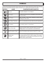 6
6
-
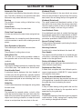 7
7
-
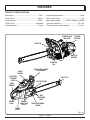 8
8
-
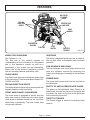 9
9
-
 10
10
-
 11
11
-
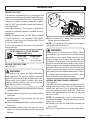 12
12
-
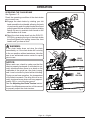 13
13
-
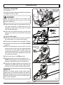 14
14
-
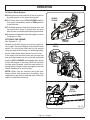 15
15
-
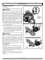 16
16
-
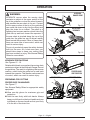 17
17
-
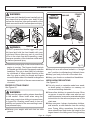 18
18
-
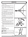 19
19
-
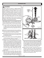 20
20
-
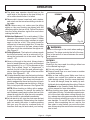 21
21
-
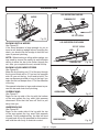 22
22
-
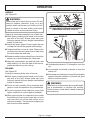 23
23
-
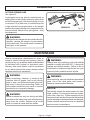 24
24
-
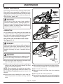 25
25
-
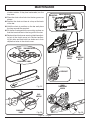 26
26
-
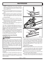 27
27
-
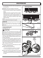 28
28
-
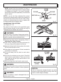 29
29
-
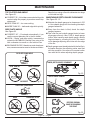 30
30
-
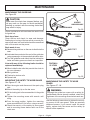 31
31
-
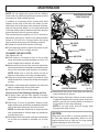 32
32
-
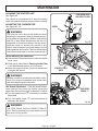 33
33
-
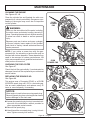 34
34
-
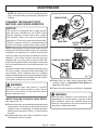 35
35
-
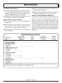 36
36
-
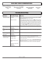 37
37
-
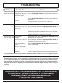 38
38
-
 39
39
-
 40
40
-
 41
41
-
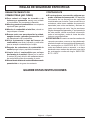 42
42
-
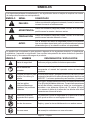 43
43
-
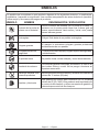 44
44
-
 45
45
-
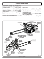 46
46
-
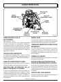 47
47
-
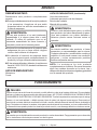 48
48
-
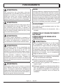 49
49
-
 50
50
-
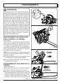 51
51
-
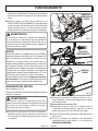 52
52
-
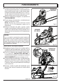 53
53
-
 54
54
-
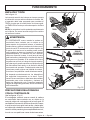 55
55
-
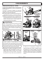 56
56
-
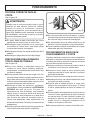 57
57
-
 58
58
-
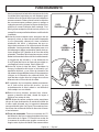 59
59
-
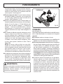 60
60
-
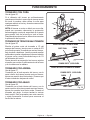 61
61
-
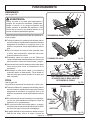 62
62
-
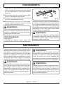 63
63
-
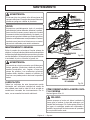 64
64
-
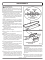 65
65
-
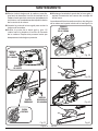 66
66
-
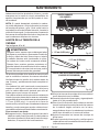 67
67
-
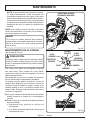 68
68
-
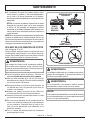 69
69
-
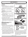 70
70
-
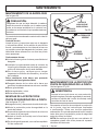 71
71
-
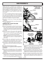 72
72
-
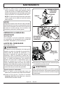 73
73
-
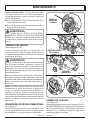 74
74
-
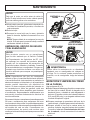 75
75
-
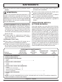 76
76
-
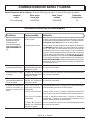 77
77
-
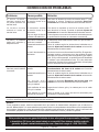 78
78
-
 79
79
-
 80
80


Black Max BM5020 El manual del propietario
- Categoría
- Motosierras eléctricas
- Tipo
- El manual del propietario
en otros idiomas
- English: Black Max BM5020 Owner's manual
Artículos relacionados
Otros documentos
-
MTD TB4516CC Manual de usuario
-
Troy-Bilt TB3516 Manual de usuario
-
Homelite UT10548 Manual de usuario
-
Ryobi RY5020 El manual del propietario
-
-
Craftsman 41CY4218793 El manual del propietario
-
Craftsman CMXGSAMCN4218 El manual del propietario
-
Ryobi RY10518 Manual de usuario
-
-
Homelite UT10582 Manual de usuario