Yamaha DIO8 Manual de usuario
- Categoría
- Equipo musical
- Tipo
- Manual de usuario
Este manual también es adecuado para

V516420 R2 1 IP 20
100 CR Printed in Japan
Owner’s Manual
DIGITAL IO BOX
E

2
Trademarks
• ADAT is registered trademark of Alesis Corporation.
• TEAC is registered trademark of TEAC Corporation.
FCC INFORMATION (U.S.A.)
1. IMPORTANT NOTICE: DO NOT MODIFY THIS UNIT! This product, when installed as indicated in the instructions contained in this manual, meets FCC
requirements. Modifications not expressly approved by Yamaha may void your authority, granted by the FCC, to use the product.
2. IMPORTANT: When connecting this product to accessories and/or another product use only high quality shielded cables. Cable/s supplied with this product MUST
be used. Follow all installation instructions. Failure to follow instructions could void your FCC authorization to use this product in the USA.
3. NOTE: This product has been tested and found to comply with the requirements listed in FCC Regulations, Part 15 for Class “B” digital devices. Compliance with
these requirements provides a reasonable level of assurance that your use of this product in a residential environment will not result in harmful interference with
other electronic devices. This equipment generates/uses radio frequencies and, if not installed and used according to the instructions found in the users manual, may
cause interference harmful to the operation of other electronic devices. Compliance with FCC regulations does not guarantee that interference will not occur in all
installations. If this product is found to be the source of interference, which can be determined by turning the unit “OFF” and “ON”, please try to eliminate the
problem by using one of the following measures: Relocate either this product or the device that is being affected by the interference. Utilize power outlets that are on
different branch (circuit breaker or fuse) circuits or install AC line filter/s. In the case of radio or TV interference, relocate/reorient the antenna. If the antenna lead-in
is 300 ohm ribbon lead, change the lead-in to coaxial type cable. If these corrective measures do not produce satisfactory results, please contact the local retailer
authorized to distribute this type of product. If you can not locate the appropriate retailer, please contact Yamaha Corporation of America, Electronic Service
Division, 6600 Orangethorpe Ave, Buena Park, CA 90620
The above statements apply ONLY to those products distributed by Yamaha Corporation of America or its subsidiaries.
WARNING: THIS APPARATUS MUST BE EARTHED
IMPORTANT
THE WIRES IN THIS MAINS LEAD ARE COLOURED IN
ACCORDANCE WITH THE FOLLOWING CODE:
GREEN-AND-YELLOW : EARTH
BLUE : NEUTRAL
BROWN : LIVE
As the colours of the wires in the mains lead of this apparatus may
not correspond with the coloured markings identifying the terminals in
your plug, proceed as follows:
The wire which is coloured GREEN and YELLOW must be
connected to the terminal in the plug which is marked by the letter E
or by the safety earth symbol or coloured GREEN and YELLOW.
The wire which is coloured BLUE must be connected to the terminal
which is marked with the letter N or coloured BLACK.
The wire which is coloured BROWN must be connected to the
terminal which is marked with the letter L or coloured RED.
* This applies only to products distributed by YAMAHA KEMBLE
MUSIC (U.K.) LTD.

3
■
Precautions
•Do not place a container with liquid or small metal
objects on top of this unit. Liquid or metal objects
inside this unit are a fire and electrical shock hazard.
•Do not allow water to enter this unit or allow the unit
to become wet. Fire or electrical shock may result.
•Connect this unit’s power cord only to an AC outlet of
the type stated in this Owner’s Manual or as marked
on the unit. Failure to do so is a fire and electrical
shock hazard.
•Be sure to connect to an appropriate outlet with a pro-
tective grounding connection. Improper grounding
can result in electrical shock.
•Do not scratch, bend, twist, pull, or heat the power
cord. A damaged power cord is a fire and electrical
shock hazard.
•Do not place heavy objects, including this unit, on top
of the power cord. A damaged power cord is a fire and
electrical shock hazard. In particular, be careful not to
place heavy objects on a power cord covered by a car-
pet.
•If you notice any abnormality, such as smoke, odor, or
noise, or if a foreign object or liquid gets inside the
unit, turn it off immediately. Remove the power cord
from the AC outlet. Consult your dealer for repair.
Using the unit in this condition is a fire and electrical
shock hazard.
• Should this unit/AC adapter/power supply be
dropped or the cabinet be damaged, turn the power
switch off, remove the power plug from the AC outlet,
and contact your dealer. If you continue using the unit
without heeding this instruction, fire or electrical
shock may result.
•If the power cord is damaged (i.e., cut or a bare wire is
exposed), ask your dealer for a replacement. Using the
unit with a damaged power cord is a fire and electrical
shock hazard.
•Do not remove the unit’s cover. You could receive an
electrical shock. If you think internal inspection,
maintenance, or repair is necessary, contact your
dealer.
•Do not modify the unit. Doing so is a fire and electri-
cal shock hazard.
•When setting up the product, make sure that the AC
outlet you are using is easily accessible. If some trou-
ble or malfunction occurs, immediately turn off the
power switch and disconnect the plug from the outlet.
Even when the power switch is turned off, electricity is
still flowing to the product at the minimum level.
When you are not using the product for a long time,
make sure to unplug the power cord from the wall AC
outlet.
•When rack-mounting the unit, allow enough free
space around the unit for normal ventilation. This
should be: 10 cm at the sides, 15 cm behind, and 30
cm above.
•For normal ventilation during use, remove the rear of
the rack or open a ventilation hole.
•If the airflow is not adequate, the unit will heat up
inside and may cause a fire.
•This unit has ventilation holes at the top and bottom
to prevent the internal temperature rising too high.
Do not block them. Blocked ventilation holes are a fire
hazard.
•Hold the power cord plug when disconnecting it from
an AC outlet. Never pull the cord. A damaged power
cord is a potential fire and electrical shock hazard.
•Do not touch the power plug with wet hands. Doing
so is a potential electrical shock hazard.
•The digital circuits of this unit may induce a slight
noise into nearby radios and TVs. If noise occurs,
relocate the affected equipment.
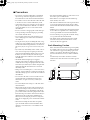
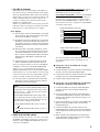
Rack Mounting Caution
If the unit is rack mounted and transported regularly,
for example, when on a tour, we recommend that the
rear of the unit be supported by fitting a pair metal
brackets, one each side. The following drawing pro-
vides the information necessary to make such brack-
ets.
Note that only one bracket is shown here and the
bracket for the other side must be bent in the opposite
direction.
86.5
20.5
3.1
4-
ø
6.5
2-R2
R2
2-R2
R5
t = 1.6
(82.1)
76.2
44.45
31.75
5.9
0
36.5
14.5
7.5
8
0
12
134
200
0
Dio8_E_Body Page 3 Wednesday, February 28, 2007 10:21 AM

4
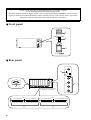
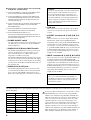
■
Front panel
■
Rear panel
Thank you for choosing the DIO8 digital IO box, specifically designed
for the Yamaha PM1D digital audio mixing system.
The DIO8 outputs and inputs digital signals (such as ADAT, TASCAM, and AES/EBU) as well as analog
signals to and from the DSP1D/DSP1D-EX engine controlled via the CS1D control surface. Up to eight
digital I/O cards and analog I/O cards can be installed on each DIO8.
I/O UNIT ID
PORT B SELECTOR
5-8
1-4
POWER
ON/ OFF
I/O UNIT ID
PORT B SELECTOR
5-8
1-4
POWER
ON/ OFF
1
2
3
DIGITAL IO BOX
12345678
75Ω
IN
ON
OFF
OUT
COM OUTPUT
B (1–4/5–8) A (1–4/1–8)
INPUT
B (1–4/5–8) A (1–4/1–8)
WORD
CLOCK
75Ω
IN
ON
OFF
OUT
OUTPUT
B (1–4/5–8) A (1–4)/(1–8)
INPUT
B (1–4/5–8) A (1–4)/(1–8)
WORD
CLOCK
COM
5
78
4
6
The illustration shows the unit
without any cards installed.
*

5
A
I/O UNIT ID indicator
This indicates the connector number (the number of
the connector used to control the DIO8) of the engine
DSP unit (DSP1D/DSP1D-EX) connected to the DIO8.
If more than one connector is connected, either A or B
will be automatically selected as the connector for
control, according to the connection status of the
INPUT and OUTPUT jacks.
If there is a problem such as an incorrectly connected
DSP unit or if the word clock is not locked, this will be
indicated by one of the following error displays.
Error displays
E1
: The OUTPUT connector of the DIO8 is connected
to the OUTPUT connector of the DSP unit. Please
connect it to the INPUT connector.
E2
: The INPUT connector of the DIO8 is connected to
the INPUT connector of the DSP unit. Please con-
nect it to the OUTPUT connector. (This will not be
displayed if the OUTPUT connector of the DIO8 is
connected.)
E3
: Either the cable connected to the INPUT or OUT-
PUT connector has become disconnected, or the
connection destination is incorrect. If the connec-
tion is correct, try replacing the cable. (This will be
displayed only if both INPUT and OUTPUT are
abnormal.)
UC
: Control signals are not being received correctly.
Make sure that the power of the DSP unit is on.
These error displays indicate an error for the INPUT/
OUTPUT A connectors if the PORT B SELECTOR
switch is set to 5-8, and indicate an error for the
INPUT/OUTPUT B connectors if the PORT B SELEC-
TOR switch is set to 1-4. Even if there is an incorrectly
connected connector, the error display will not appear
if there is another control connector that is usable.
UL
: The word clock is not locked. Make sure that the
word clock source is selected correctly, and that
the cable is connected correctly.
B
PORT B SELECTOR switch
Use this switch to select slots 1-4 or slots 5-8 to assign
the INPUT A/OUTPUT A connectors (referred to as
PORT A) and the INPUT B/OUTPUT B connectors
(referred to as PORT B).
If the PORT B SELECTOR is set to 5-8,
slots 1-4 are
assigned to PORT A and slots 5-8 are assigned to
PORT B for input and output signals.
If the PORT B SELECTOR is set to 1-4,
only PORT B
is available for input and output signals via slots 1-4.
In reality, slot 1-4 input signals are routed to OUT-
PUT A, and the INPUT B signal is output to slots 5-8.
If you wish to route slot 1-4 signals to both OUTPUT
A and B, use this setting.
To connect the DIO8 to the DSP1D/DSP1D-EX, make
one of the following settings, depending on your
application.
●
Using slots 1-8 of the DIO8 with a single
DSP1D/DSP1D-EX
1) Connect the INPUT A and B connectors of the DIO8 to
OUTPUT slot 1-6 of the DSP1D/DSP1D-EX.
2) Connect the OUTPUT A and B connectors of the DIO8
to INPUT slot 1-10 of the DSP1D/DSP1D-EX.
3) Set the PORT B SELECTOR to 5-8.
●
Using slots 1-4 of the DIO8 with two DSP1D/
DSP1D-EXs for Mirror mode operation
1) Connect the INPUT A connector of the DIO8 to the
OUTPUT slot 1-6 connector of the first DSP1D/
DSP1D-EX.
2) Connect the INPUT B connector of the DIO8 to the
second DSP1D/DSP1D-EX OUTPUT slot connector
with the same number as the first unit’s slot you con-
nected in Step 1).
3) Connect the OUTPUT A connector of the DIO8 to the
INPUT connector for INPUT slot 1-10 of the first
DSP1D/DSP1D-EX.
4) Connect the INPUT B connector to the second
DSP1D/DSP1D-EX OUTPUT slot connector with the
same number as the first unit’s slot you connected in
Step 3).
5) When you place the unit into Mirror mode from the
CS1D, the PORT B SELECTOR changes its setting,
depending on the operating status.
Note:
You can change the PORT B SELECTOR setting by
sending the control signal from the CS1D. At this
time, two dots (“. .”) light up besides the indicator
message described above.
If the PORT B SELECTOR switch setting on the
unit is different from the actual operation, one of
the following messages and the indicator message
described above will appear alternately.
• If the PORT B SELECTOR switches to slots 1-4:
“”
• If the PORT B SELECTOR switches to slots 5-8:
“”
“ ”
“ ”

6
●
Using slots 1-4 input signals with two DSP1D/
DSP1D-EXs simultaneously
1) Connect the INPUT A connector of the DIO8 to OUT-
PUT slot 1-6 of the first DSP1D/DSP1D-EX.
2) Connect the INPUT B connector of the DIO8 to the
second DSP1D/DSP1D-EX OUTPUT slot connector
with the same ID number as the first unit’s slot you
connected in Step 1).
3) Connect the OUTPUT A connector of the DIO8 to the
INPUT connector for INPUT slot 1-10 of the first
DSP1D/DSP1D-EX.
4) Connect the INPUT B connector to the second
DSP1D/DSP1D-EX OUTPUT slot connector.
5) Set the PORT B SELECTOR to 1-4.
Slot 1-4 input signals will be output from OUTPUT A
and B. However, the output signal will be the same as
the signal input to INPUT B.
C
POWER ON/OFF switch
Use this switch to turn the power to the DIO8 on and
off. When the power is turned on, the I/O UNIT ID
indicator lights up.
D
WORD CLOCK IN jack, ON/OFF switch
The WORD CLOCK IN jack is used to provide word
clock to the DIO8 from a clock generator or a con-
nected external device. Use a BNC cable with an
impedance of 75
Ω
for connection.
The WORD CLOCK ON/OFF switch is used to termi-
nate the word clock connection. Basically, if the DIO8
is the last device of the word clock chain, or if nothing
is connected to the WORD CLOCK IN/OUT jacks, set
this switch to ON.
E
WORD CLOCK OUT jacks
The WORD CLOCK OUT jacks are used to provide
word clock from the DIO8 to the connected external
device, such as digital MTR or DAT recorder. Use a
BNC cable with an impedance of 75
Ω
for connection.
F
COM port
This connector is provided for future system expan-
sion, but it is not operative in the current software
version.
G
OUTPUT connectors A (1-4)/(1-8), B (1-4/
5-8)
These connectors are used to output multi-channel
digital audio signals to the DSP1D/DSP1D-EX.
Depending on the setting of the PORT B SELECTOR,
assignment between the OUTPUT A and B connec-
tors and slots 1-8 varies. For more information, refer
to
2
PORT B SELECTOR. Be sure to use the included
genuine Yamaha half-pitch 68-pin cable for connec-
tion. Optional genuine Yamaha cables in a variety of
lengths are also available.
H
INPUT connectors A (1-4)/(1-8), B (1-4/5-8)
These connectors are used to input multi-channel dig-
ital audio signals from the DSP1D/DSP1D-EX.
Depending on the setting of the PORT B SELECTOR,
assignment between the INPUT A and B connectors
and slots 1-8 varies. For more information, refer to
2
PORT B SELECTOR. Be sure to use the included gen-
uine Yamaha half-pitch 68-pin cable for connection.
Optional genuine Yamaha cables in a variety of
lengths are also available.
The following table shows optional Yamaha digital I/O cards and analog I/O cards that can be installed into the slots of dig-
ital IO unit DIO8.
*: Manufactured by Apogee Corporation
It is not possible to install and use a total of five or more
AP8AD/AP8DA cards. Also, if you are using AP8AD/
AP8DA cards simultaneously with MY8-AD/MY4-AD/
MY4-DA cards, there are restrictions on the number of
cards, as described on the next page. Never exceed the
allowable number of cards, since attempting to use a
greater number of cards than allowed may damage the
DIO8 due to excessive current. If you are not using
AP8AD or AP8DA cards, or if you are using AP8AD or
AP8DA cards simultaneously with an MY8-TD/MY8-AT/
MY8-AE card, there is no limitation on the number of
MY8-TD/MY8-AT/MY8-AE cards that can be used.
Caution:
If you are using the MY8-AT card to handle ADAT
format signals, synchronization may tend to be
lost easily depending on the device that is con-
nected. For the most reliable synchronization, we
recommend that the word clock for digital audio
devices being used together be taken from a con-
nector other than the ADAT-format connector,
such as this connector.
Note:
The “(1-8)” function labelled at the INPUT A/
OUTPUT A connectors is provided for future sys-
tem expansion, but it is not operative in the cur-
rent software version.
Card Format Input Output
MY8-TD TASCAM 8 IN 8 OUT
MY8-AT ADAT 8 IN 8 OUT
MY8-AE AES/EBU 8 IN 8 OUT
MY8-AD ANALOG IN 8 IN —
MY4-AD ANALOG IN 4 IN —
MY4-DA ANALOG OUT — 4 OUT
AP8AD* ANALOG IN 8 IN —
AP8DA* ANALOG OUT — 8 OUT

7
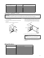
Installing an optional I/O card
1. Turn off the power to the DIO8 and remove the power
cord from the DIO8.
2. Loosen two screws as shown below and remove the
slot cover.
Keep the cover in a safe place for future use.
3. Align the edge of the card with the guide rail inside the
slot as shown below and insert the card into the slot.
Push in the card until the connector on the card is
securely plugged into the terminal inside the DIO8.
4. Fix the card by tightening the two screws.
5. Connect the power cord to the DIO8 and turn the
power on.
■
Specifications
[AP8AD]+[AP8DA] cards used
[MY8-AD]+[MY4-AD]+
[MY4-DA] cards used
[MY8-TD]+[MY8-AT]+[MY8-AE] cards used
Total 0 cards Up to a total of 8 cards
Total 1 card Up to 6 cards Up to the number of vacant DIO8 slots
Total 2 cards Up to 4 cards Up to the number of vacant DIO8 slots
Total 3 cards Up to 2 cards Up to the number of vacant DIO8 slots
Total 4 card Up to 1 card Up to the number of vacant DIO8 slots
Total 5 or more cards cannot be used ——
Important!
Before installing an optional I/O card, be sure to turn off the power to the DIO8 and remove the power cord from the
DIO8. Otherwise, you may be in danger of electrical shock, and/or the unit or the card may be damaged.
A
(1
–
4
/1
–
8
)
1
2
Caution:
Be sure to tighten the screws securely. Otherwise,
the card may not be appropriately grounded.
1
2
Guide rail
Sampling frequency (external sync) 39.69 kHz – 50.88 kHz
Power supply
USA and Canada : 120 V, 60 Hz
Others : 230 V, 50 Hz
Power consumption 70W
Dimensions (W
×
H
×
D) 480 mm
×
185.5 mm
×
411.6 mm
Weight 15.5 kg
Operating temperature 10 – 35˚C
Power cord length 1.5 m
Accessories Connection cable (68-pin, D-sub, half-pitch) x 2, Length: 3m

8
I/Os
Slots
Eight slots (slots 1-8) are available on the DIO8 for installing digital I/O cards and analog I/O cards.
Slot 1 supports a serial interface card (not released yet).
●
Optional interface cards
*: Manufactured by Apogee Corporation
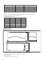
■
Dimensions
• Specifications and appearance are subject to change without notice for improvement.
• For European Model
Purchaser/User information specified in EN55103-1 and EN55103-2.
Inrush Current: 10A
Conformed Environment: E1, E2, E3 and E4.
I/O connectors Level Type
INPUT A, B RS422 D-sub, half-pitch, 68-pin connector (female)
OUTPUT A, B RS422 D-sub, half-pitch, 68-pin connector (female)
COM RS232C D-sub,9-pin connector (male)
WORD CLOCK IN TTL/75
Ω
(ON/OFF)
*1
BNC connector
WORD CLOCK OUT (X4) TTL/75
Ω
BNC connector
*1
On the rear panel
Card Format Input Output
MY8-TD TASCAM 8 IN 8 OUT
MY8-AT ADAT 8 IN 8 OUT
MY8-AE AES/EBU 8 IN 8 OUT
MY8-AD ANALOG IN 8 IN —
MY4-AD ANALOG IN 4 IN —
MY4-DA ANALOG OUT — 4 OUT
AP8AD* ANALOG IN 8 IN —
AP8DA* ANALOG OUT — 8 OUT
400
411.6
176
480
185.5
I/O UNIT ID
PORT B SELECTOR
5-8
1-4
POWER
ON/ OFF
9.5
unit: mm

YAMAHA CORPORATION
Pro Audio & Digital Musical Instrument Division
P.O. Box 3, Hamamatsu, 430-8651, Japan
Transcripción de documentos
DIGITAL IO BOX Owner’s Manual V516420 R2 1 IP 20 100 CR Printed in Japan E FCC INFORMATION (U.S.A.) 1. IMPORTANT NOTICE: DO NOT MODIFY THIS UNIT! This product, when installed as indicated in the instructions contained in this manual, meets FCC requirements. Modifications not expressly approved by Yamaha may void your authority, granted by the FCC, to use the product. 2. IMPORTANT: When connecting this product to accessories and/or another product use only high quality shielded cables. Cable/s supplied with this product MUST be used. Follow all installation instructions. Failure to follow instructions could void your FCC authorization to use this product in the USA. 3. NOTE: This product has been tested and found to comply with the requirements listed in FCC Regulations, Part 15 for Class “B” digital devices. Compliance with these requirements provides a reasonable level of assurance that your use of this product in a residential environment will not result in harmful interference with other electronic devices. This equipment generates/uses radio frequencies and, if not installed and used according to the instructions found in the users manual, may cause interference harmful to the operation of other electronic devices. Compliance with FCC regulations does not guarantee that interference will not occur in all installations. If this product is found to be the source of interference, which can be determined by turning the unit “OFF” and “ON”, please try to eliminate the problem by using one of the following measures: Relocate either this product or the device that is being affected by the interference. Utilize power outlets that are on different branch (circuit breaker or fuse) circuits or install AC line filter/s. In the case of radio or TV interference, relocate/reorient the antenna. If the antenna lead-in is 300 ohm ribbon lead, change the lead-in to coaxial type cable. If these corrective measures do not produce satisfactory results, please contact the local retailer authorized to distribute this type of product. If you can not locate the appropriate retailer, please contact Yamaha Corporation of America, Electronic Service Division, 6600 Orangethorpe Ave, Buena Park, CA 90620 The above statements apply ONLY to those products distributed by Yamaha Corporation of America or its subsidiaries. WARNING: THIS APPARATUS MUST BE EARTHED IMPORTANT THE WIRES IN THIS MAINS LEAD ARE COLOURED IN ACCORDANCE WITH THE FOLLOWING CODE: GREEN-AND-YELLOW : EARTH BLUE : NEUTRAL BROWN : LIVE As the colours of the wires in the mains lead of this apparatus may not correspond with the coloured markings identifying the terminals in your plug, proceed as follows: The wire which is coloured GREEN and YELLOW must be connected to the terminal in the plug which is marked by the letter E or by the safety earth symbol or coloured GREEN and YELLOW. The wire which is coloured BLUE must be connected to the terminal which is marked with the letter N or coloured BLACK. The wire which is coloured BROWN must be connected to the terminal which is marked with the letter L or coloured RED. * This applies only to products distributed by YAMAHA KEMBLE MUSIC (U.K.) LTD. Trademarks • ADAT is registered trademark of Alesis Corporation. • TEAC is registered trademark of TEAC Corporation. 2 Dio8_E_Body Page 3 Wednesday, February 28, 2007 10:21 AM ■ Precautions • The digital circuits of this unit may induce a slight noise into nearby radios and TVs. If noise occurs, relocate the affected equipment. Rack Mounting Caution If the unit is rack mounted and transported regularly, for example, when on a tour, we recommend that the rear of the unit be supported by fitting a pair metal brackets, one each side. The following drawing provides the information necessary to make such brackets. Note that only one bracket is shown here and the bracket for the other side must be bent in the opposite direction. • If you notice any abnormality, such as smoke, odor, or noise, or if a foreign object or liquid gets inside the unit, turn it off immediately. Remove the power cord from the AC outlet. Consult your dealer for repair. Using the unit in this condition is a fire and electrical shock hazard. • Should this unit/AC adapter/power supply be dropped or the cabinet be damaged, turn the power switch off, remove the power plug from the AC outlet, and contact your dealer. If you continue using the unit without heeding this instruction, fire or electrical shock may result. 2-R2 2-R2 (82.1) 76.2 • If the power cord is damaged (i.e., cut or a bare wire is exposed), ask your dealer for a replacement. Using the unit with a damaged power cord is a fire and electrical shock hazard. 31.75 0 7.5 14.5 0 5.9 4- ø 6.5 36.5 • Do not remove the unit’s cover. You could receive an electrical shock. If you think internal inspection, maintenance, or repair is necessary, contact your dealer. 44.45 86.5 • Do not place heavy objects, including this unit, on top of the power cord. A damaged power cord is a fire and electrical shock hazard. In particular, be careful not to place heavy objects on a power cord covered by a carpet. • Do not touch the power plug with wet hands. Doing so is a potential electrical shock hazard. 20.5 • Do not scratch, bend, twist, pull, or heat the power cord. A damaged power cord is a fire and electrical shock hazard. • Hold the power cord plug when disconnecting it from an AC outlet. Never pull the cord. A damaged power cord is a potential fire and electrical shock hazard. R5 R2 200 • Be sure to connect to an appropriate outlet with a protective grounding connection. Improper grounding can result in electrical shock. • This unit has ventilation holes at the top and bottom to prevent the internal temperature rising too high. Do not block them. Blocked ventilation holes are a fire hazard. 134 • Connect this unit’s power cord only to an AC outlet of the type stated in this Owner’s Manual or as marked on the unit. Failure to do so is a fire and electrical shock hazard. • If the airflow is not adequate, the unit will heat up inside and may cause a fire. 3.1 • Do not allow water to enter this unit or allow the unit to become wet. Fire or electrical shock may result. • For normal ventilation during use, remove the rear of the rack or open a ventilation hole. 0 8 12 • Do not place a container with liquid or small metal objects on top of this unit. Liquid or metal objects inside this unit are a fire and electrical shock hazard. t = 1.6 • Do not modify the unit. Doing so is a fire and electrical shock hazard. • When setting up the product, make sure that the AC outlet you are using is easily accessible. If some trouble or malfunction occurs, immediately turn off the power switch and disconnect the plug from the outlet. Even when the power switch is turned off, electricity is still flowing to the product at the minimum level. When you are not using the product for a long time, make sure to unplug the power cord from the wall AC outlet. • When rack-mounting the unit, allow enough free space around the unit for normal ventilation. This should be: 10 cm at the sides, 15 cm behind, and 30 cm above. 3 Thank you for choosing the DIO8 digital IO box, specifically designed for the Yamaha PM1D digital audio mixing system. The DIO8 outputs and inputs digital signals (such as ADAT, TASCAM, and AES/EBU) as well as analog signals to and from the DSP1D/DSP1D-EX engine controlled via the CS1D control surface. Up to eight digital I/O cards and analog I/O cards can be installed on each DIO8. ■ Front panel I/O UNIT ID 1 PORT B SELECTOR 5-8 1-4 2 I/O UNIT ID PORT B SELECTOR 5-8 POWER ON/ OFF 1-4 POWER ON/ OFF 3 DIGITAL IO BOX ■ Rear panel IN 4 75Ω OFF ON WORD CLOCK 8 7 6 5 4 3 2 1 IN COM 75Ω OFF ON WORD CLOCK OUT OUT COM 6 B (1–4/5–8) OUTPUT A (1–4/1–8) B (1–4/5–8) INPUT A (1–4/1–8) illustration shows the unit * The without any cards installed. B (1–4/5–8) OUTPUT 7 4 A (1–4)/(1–8) B (1–4/5–8) INPUT 8 A (1–4)/(1–8) 5 E1: The OUTPUT connector of the DIO8 is connected to the OUTPUT connector of the DSP unit. Please connect it to the INPUT connector. E2: The INPUT connector of the DIO8 is connected to the INPUT connector of the DSP unit. Please connect it to the OUTPUT connector. (This will not be displayed if the OUTPUT connector of the DIO8 is connected.) E3: Either the cable connected to the INPUT or OUTPUT connector has become disconnected, or the connection destination is incorrect. If the connection is correct, try replacing the cable. (This will be displayed only if both INPUT and OUTPUT are abnormal.) UC: Control signals are not being received correctly. Make sure that the power of the DSP unit is on. These error displays indicate an error for the INPUT/ OUTPUT A connectors if the PORT B SELECTOR switch is set to 5-8, and indicate an error for the INPUT/OUTPUT B connectors if the PORT B SELECTOR switch is set to 1-4. Even if there is an incorrectly connected connector, the error display will not appear if there is another control connector that is usable. UL: The word clock is not locked. Make sure that the word clock source is selected correctly, and that the cable is connected correctly. Note: You can change the PORT B SELECTOR setting by sending the control signal from the CS1D. At this time, two dots (“. .”) light up besides the indicator message described above. If the PORT B SELECTOR switch setting on the unit is different from the actual operation, one of the following messages and the indicator message described above will appear alternately. • If the PORT B SELECTOR switches to slots 1-4: “ ” • If the PORT B SELECTOR switches to slots 5-8: “ ” B PORT B SELECTOR switch Use this switch to select slots 1-4 or slots 5-8 to assign the INPUT A/OUTPUT A connectors (referred to as PORT A) and the INPUT B/OUTPUT B connectors (referred to as PORT B). PORT B SELECTOR is set to “5-8” Slot 1 Slot 2 Slot 3 Slot 4 INPUT A OUTPUT A Error displays If the PORT B SELECTOR is set to 1-4, only PORT B is available for input and output signals via slots 1-4. In reality, slot 1-4 input signals are routed to OUTPUT A, and the INPUT B signal is output to slots 5-8. If you wish to route slot 1-4 signals to both OUTPUT A and B, use this setting. Slot 5 Slot 6 Slot 7 Slot 8 INPUT B OUTPUT B This indicates the connector number (the number of the connector used to control the DIO8) of the engine DSP unit (DSP1D/DSP1D-EX) connected to the DIO8. If more than one connector is connected, either A or B will be automatically selected as the connector for control, according to the connection status of the INPUT and OUTPUT jacks. If there is a problem such as an incorrectly connected DSP unit or if the word clock is not locked, this will be indicated by one of the following error displays. If the PORT B SELECTOR is set to 5-8, slots 1-4 are assigned to PORT A and slots 5-8 are assigned to PORT B for input and output signals. PORT B SELECTOR is set to “1-4” Slot 1 Slot 2 Slot 3 Slot 4 INPUT B OUTPUT B OUTPUT A A I/O UNIT ID indicator To connect the DIO8 to the DSP1D/DSP1D-EX, make one of the following settings, depending on your application. ● Using slots 1-8 of the DIO8 with a single DSP1D/DSP1D-EX 1) Connect the INPUT A and B connectors of the DIO8 to OUTPUT slot 1-6 of the DSP1D/DSP1D-EX. 2) Connect the OUTPUT A and B connectors of the DIO8 to INPUT slot 1-10 of the DSP1D/DSP1D-EX. 3) Set the PORT B SELECTOR to 5-8. ● Using slots 1-4 of the DIO8 with two DSP1D/ DSP1D-EXs for Mirror mode operation 1) Connect the INPUT A connector of the DIO8 to the OUTPUT slot 1-6 connector of the first DSP1D/ DSP1D-EX. 2) Connect the INPUT B connector of the DIO8 to the second DSP1D/DSP1D-EX OUTPUT slot connector with the same number as the first unit’s slot you connected in Step 1). 3) Connect the OUTPUT A connector of the DIO8 to the INPUT connector for INPUT slot 1-10 of the first DSP1D/DSP1D-EX. 4) Connect the INPUT B connector to the second DSP1D/DSP1D-EX OUTPUT slot connector with the same number as the first unit’s slot you connected in Step 3). 5) When you place the unit into Mirror mode from the CS1D, the PORT B SELECTOR changes its setting, depending on the operating status. 5 ● Using slots 1-4 input signals with two DSP1D/ DSP1D-EXs simultaneously 1) Connect the INPUT A connector of the DIO8 to OUTPUT slot 1-6 of the first DSP1D/DSP1D-EX. 2) Connect the INPUT B connector of the DIO8 to the second DSP1D/DSP1D-EX OUTPUT slot connector with the same ID number as the first unit’s slot you connected in Step 1). 3) Connect the OUTPUT A connector of the DIO8 to the INPUT connector for INPUT slot 1-10 of the first DSP1D/DSP1D-EX. 4) Connect the INPUT B connector to the second DSP1D/DSP1D-EX OUTPUT slot connector. 5) Set the PORT B SELECTOR to 1-4. Slot 1-4 input signals will be output from OUTPUT A and B. However, the output signal will be the same as the signal input to INPUT B. C POWER ON/OFF switch Use this switch to turn the power to the DIO8 on and off. When the power is turned on, the I/O UNIT ID indicator lights up. D WORD CLOCK IN jack, ON/OFF switch The WORD CLOCK IN jack is used to provide word clock to the DIO8 from a clock generator or a connected external device. Use a BNC cable with an impedance of 75 Ω for connection. The WORD CLOCK ON/OFF switch is used to terminate the word clock connection. Basically, if the DIO8 is the last device of the word clock chain, or if nothing is connected to the WORD CLOCK IN/OUT jacks, set this switch to ON. E WORD CLOCK OUT jacks The WORD CLOCK OUT jacks are used to provide word clock from the DIO8 to the connected external device, such as digital MTR or DAT recorder. Use a BNC cable with an impedance of 75 Ω for connection. Caution: If you are using the MY8-AT card to handle ADAT format signals, synchronization may tend to be lost easily depending on the device that is connected. For the most reliable synchronization, we recommend that the word clock for digital audio devices being used together be taken from a connector other than the ADAT-format connector, such as this connector. F COM port This connector is provided for future system expansion, but it is not operative in the current software version. G OUTPUT connectors A (1-4)/(1-8), B (1-4/ 5-8) These connectors are used to output multi-channel digital audio signals to the DSP1D/DSP1D-EX. Depending on the setting of the PORT B SELECTOR, assignment between the OUTPUT A and B connectors and slots 1-8 varies. For more information, refer to 2 PORT B SELECTOR. Be sure to use the included genuine Yamaha half-pitch 68-pin cable for connection. Optional genuine Yamaha cables in a variety of lengths are also available. H INPUT connectors A (1-4)/(1-8), B (1-4/5-8) These connectors are used to input multi-channel digital audio signals from the DSP1D/DSP1D-EX. Depending on the setting of the PORT B SELECTOR, assignment between the INPUT A and B connectors and slots 1-8 varies. For more information, refer to 2 PORT B SELECTOR. Be sure to use the included genuine Yamaha half-pitch 68-pin cable for connection. Optional genuine Yamaha cables in a variety of lengths are also available. Note: The “(1-8)” function labelled at the INPUT A/ OUTPUT A connectors is provided for future system expansion, but it is not operative in the current software version. The following table shows optional Yamaha digital I/O cards and analog I/O cards that can be installed into the slots of digital IO unit DIO8. It is not possible to install and use a total of five or more Card Format Input Output AP8AD/AP8DA cards. Also, if you are using AP8AD/ AP8DA cards simultaneously with MY8-AD/MY4-AD/ MY8-TD TASCAM 8 IN 8 OUT MY4-DA cards, there are restrictions on the number of MY8-AT ADAT 8 IN 8 OUT cards, as described on the next page. Never exceed the MY8-AE AES/EBU 8 IN 8 OUT allowable number of cards, since attempting to use a MY8-AD ANALOG IN 8 IN — greater number of cards than allowed may damage the MY4-AD ANALOG IN 4 IN — DIO8 due to excessive current. If you are not using AP8AD or AP8DA cards, or if you are using AP8AD or MY4-DA ANALOG OUT — 4 OUT AP8DA cards simultaneously with an MY8-TD/MY8-AT/ AP8AD* ANALOG IN 8 IN — MY8-AE card, there is no limitation on the number of AP8DA* ANALOG OUT — 8 OUT MY8-TD/MY8-AT/MY8-AE cards that can be used. *: Manufactured by Apogee Corporation 6 [AP8AD]+[AP8DA] cards used [MY8-AD]+[MY4-AD]+ [MY4-DA] cards used Total 0 cards [MY8-TD]+[MY8-AT]+[MY8-AE] cards used Up to a total of 8 cards Total 1 card Up to 6 cards Up to the number of vacant DIO8 slots Total 2 cards Up to 4 cards Up to the number of vacant DIO8 slots Total 3 cards Up to 2 cards Up to the number of vacant DIO8 slots Total 4 card Up to 1 card Up to the number of vacant DIO8 slots Total 5 or more cards cannot be used — — Installing an optional I/O card Important! Before installing an optional I/O card, be sure to turn off the power to the DIO8 and remove the power cord from the DIO8. Otherwise, you may be in danger of electrical shock, and/or the unit or the card may be damaged. 1. Turn off the power to the DIO8 and remove the power cord from the DIO8. 2. Loosen two screws as shown below and remove the slot cover. 3. Align the edge of the card with the guide rail inside the slot as shown below and insert the card into the slot. Push in the card until the connector on the card is securely plugged into the terminal inside the DIO8. Keep the cover in a safe place for future use. 1 1 2 2 Guide rail ) –8 /1 –4 A (1 4. Fix the card by tightening the two screws. Caution: Be sure to tighten the screws securely. Otherwise, the card may not be appropriately grounded. 5. Connect the power cord to the DIO8 and turn the power on. ■ Specifications Sampling frequency (external sync) Power supply 39.69 kHz – 50.88 kHz USA and Canada : 120 V, 60 Hz Others : 230 V, 50 Hz Power consumption 70W Dimensions (W × H × D) 480 mm × 185.5 mm × 411.6 mm Weight 15.5 kg Operating temperature 10 – 35˚C Power cord length 1.5 m Accessories Connection cable (68-pin, D-sub, half-pitch) x 2, Length: 3m 7 I/Os I/O connectors Level Type INPUT A, B RS422 D-sub, half-pitch, 68-pin connector (female) OUTPUT A, B RS422 D-sub, half-pitch, 68-pin connector (female) COM RS232C D-sub,9-pin connector (male) WORD CLOCK IN TTL/75 Ω (ON/OFF) *1 BNC connector WORD CLOCK OUT (X4) TTL/75 Ω BNC connector *1 On the rear panel Slots Eight slots (slots 1-8) are available on the DIO8 for installing digital I/O cards and analog I/O cards. Slot 1 supports a serial interface card (not released yet). ● Optional interface cards Card MY8-TD Format TASCAM Input 8 IN Output 8 OUT MY8-AT ADAT 8 IN 8 OUT MY8-AE AES/EBU 8 IN 8 OUT MY8-AD ANALOG IN 8 IN — MY4-AD ANALOG IN 4 IN — MY4-DA ANALOG OUT — 4 OUT AP8AD* ANALOG IN 8 IN — AP8DA* ANALOG OUT — 8 OUT *: Manufactured by Apogee Corporation 411.6 Dimensions 400 ■ 480 1-4 185.5 PORT B SELECTOR 5-8 176 I/O UNIT ID POWER ON/ OFF 9.5 unit: mm • Specifications and appearance are subject to change without notice for improvement. • For European Model Purchaser/User information specified in EN55103-1 and EN55103-2. Inrush Current: 10A Conformed Environment: E1, E2, E3 and E4. 8 YAMAHA CORPORATION Pro Audio & Digital Musical Instrument Division P.O. Box 3, Hamamatsu, 430-8651, Japan-
 1
1
-
 2
2
-
 3
3
-
 4
4
-
 5
5
-
 6
6
-
 7
7
-
 8
8
-
 9
9


Yamaha DIO8 Manual de usuario
- Categoría
- Equipo musical
- Tipo
- Manual de usuario
- Este manual también es adecuado para
en otros idiomas
- français: Yamaha DIO8 Manuel utilisateur
- italiano: Yamaha DIO8 Manuale utente
- English: Yamaha DIO8 User manual
- Deutsch: Yamaha DIO8 Benutzerhandbuch
- русский: Yamaha DIO8 Руководство пользователя
- Nederlands: Yamaha DIO8 Handleiding
- português: Yamaha DIO8 Manual do usuário
- dansk: Yamaha DIO8 Brugermanual
- polski: Yamaha DIO8 Instrukcja obsługi
- čeština: Yamaha DIO8 Uživatelský manuál
- svenska: Yamaha DIO8 Användarmanual
- 日本語: Yamaha DIO8 ユーザーマニュアル
- Türkçe: Yamaha DIO8 Kullanım kılavuzu
- română: Yamaha DIO8 Manual de utilizare
Artículos relacionados
-
Yamaha CS1D El manual del propietario
-
-
Yamaha 2 Manual de usuario
-
-
-
-
-
-
-