
E
for
Owner’s Manual
V509080 R1 1 IP 12
01 03 500 CP Printed in Japan

2
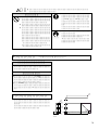
■
Precautions
• Do not place a container with liquid or small metal
objects on top of this unit. Liquid or metal objects
inside this unit are a fire and electrical shock hazard.
• Connect the power cord only to an AC outlet of the
type stated in this
Owner’s Manual
or as marked on
the power supply unit. Failure to do so is a fire and
electrical shock hazard.
• Do not locate the power supply unit in a place subject
to excessive heat or in direct sunlight. This could be a
fire hazard.
• Do not place the power supply unit in a place subject
to excessive humidity or dust. This could be a fire and
electrical shock hazard.
• Do not allow water to enter this unit or allow the unit
to become wet. Fire or electrical shock may result.
• Do not plug several devices into the same AC outlet.
This may overload the AC outlet, and could be a fire
and electrical shock hazard. It may also affect the per-
formance of some equipment.
• Do not place heavy objects on the power cord. A dam-
aged power cord is a potential fire and electrical shock
hazard.
• If the power cord is damaged (i.e., cut or a bare wire is
exposed), ask your dealer for a replacement. Using the
power supply unit in this condition is a fire and shock
hazard.
• Be sure to ground the unit to avoid the risk of electri-
cal shock
• Do not scratch, bend, twist, pull, or heat the power
cord. A damaged power cord is a fire and electrical
shock hazard.
• Do not touch the power plug with wet hands. Doing
so is a potential electrical shock hazard.
FCC INFORMATION (U.S.A.)
1. IMPORTANT NOTICE: DO NOT MODIFY THIS UNIT! This product, when installed as indicated in the instructions contained in this manual, meets FCC
requirements. Modifications not expressly approved by Yamaha may void your authority, granted by the FCC, to use the product.
2. IMPORTANT: When connecting this product to accessories and/or another product use only high quality shielded cables. Cable/s supplied with this product MUST
be used. Follow all installation instructions. Failure to follow instructions could void your FCC authorization to use this product in the USA.
3. NOTE: This product has been tested and found to comply with the requirements listed in FCC Regulations, Part 15 for Class “B” digital devices. Compliance with
these requirements provides a reasonable level of assurance that your use of this product in a residential environment will not result in harmful interference with
other electronic devices. This equipment generates/uses radio frequencies and, if not installed and used according to the instructions found in the users manual, may
cause interference harmful to the operation of other electronic devices. Compliance with FCC regulations does not guarantee that interference will not occur in all
installations. If this product is found to be the source of interference, which can be determined by turning the unit “OFF” and “ON”, please try to eliminate the
problem by using one of the following measures: Relocate either this product or the device that is being affected by the interference. Utilize power outlets that are on
different branch (circuit breaker or fuse) circuits or install AC line filter/s. In the case of radio or TV interference, relocate/reorient the antenna. If the antenna lead-in
is 300 ohm ribbon lead, change the lead-in to coaxial type cable. If these corrective measures do not produce satisfactory results, please contact the local retailer
authorized to distribute this type of product. If you can not locate the appropriate retailer, please contact Yamaha Corporation of America, Electronic Service
Division, 6600 Orangethorpe Ave, Buena Park, CA 90620
The above statements apply ONLY to those products distributed by Yamaha Corporation of America or its subsidiaries.
WARNING: THIS APPARATUS MUST BE EARTHED
IMPORTANT
THE WIRES IN THIS MAINS LEAD ARE COLOURED IN
ACCORDANCE WITH THE FOLLOWING CODE:
GREEN-AND-YELLOW : EARTH
BLUE : NEUTRAL
BROWN : LIVE
As the colours of the wires in the mains lead of this apparatus may
not correspond with the coloured markings identifying the terminals in
your plug, proceed as follows:
The wire which is coloured GREEN and YELLOW must be
connected to the terminal in the plug which is marked by the letter E
or by the safety earth symbol or coloured GREEN and YELLOW.
The wire which is coloured BLUE must be connected to the terminal
which is marked with the letter N or coloured BLACK.
The wire which is coloured BROWN must be connected to the
terminal which is marked with the letter L or coloured RED.
* This applies only to products distributed by YAMAHA KEMBLE
MUSIC (U.K.) LTD.

3
• Hold the power cord plug when disconnecting from
an AC outlet. Never pull the cord. Damaging the
power cord in this way is a potential fire and electrical
shock hazard.
• Do not place small metal objects on top of the power
supply unit. Metal objects inside the power supply
unit are a fire and electrical shock hazard.
• Do not block the power supply unit ventilation slots.
The power supply unit has ventilation slots at the
front and rear to prevent the internal temperature
from rising. Blocked ventilation slots are a fire hazard.
• Leave a reasonable amount of free-air space around
the power supply unit.
• If the power supply unit is to be rack mounted, leave
at least 10 cm free above the top panel and behind the
rear panel. When the power supply unit is in use,
remove the rear of the rack, or open its ventilation
slots to prevent overheating, which could be a fire
hazard.
• Do not try to modify the power supply unit. This
could be a fire and electrical shock hazard.
• The power supply unit operating temperature is
between 10˚C and 35˚C (58˚F and 95˚F).
• If you notice any abnormality—such as smoke, odor,
or noise—turn off the power supply unit immediately.
Remove the power cord from the AC outlet. Confirm
that the abnormality is no longer present. Consult
your dealer for repair. Using the power supply unit in
this condition is a fire and shock hazard.
• If a foreign object or water gets inside the power sup-
ply unit, turn it off immediately. Remove the power
cord from the AC outlet. Consult your dealer for
repair. Using the power supply unit in this condition
is a fire and electrical shock hazard.
• If you plan not to use the power supply unit for a long
period of time, remove the power cord from the AC
outlet. Leaving the power supply unit connected is a
fire hazard.
• Do not use benzene, thinner, cleaning detergent, or a
chemical cloth to clean the power supply unit. Use
only a soft, dry cloth.
• The power supply unit uses high-frequency digital cir-
cuits that may cause interference on radios and televi-
sions placed close to it. If interference does occur,
relocate the affected equipment.
• The power supply unit is equipped with the ground
connector to avoid the risk of electrical shock.
Be sure to ground the unit before you insert the power
plug into an AC outlet.
If the power cord has three pins and the ground con-
nector on the AC outlet is grounded, the unit will be
grounded effectively.
Operating Notes
• The power must be turned on/off using the POWER
switch of this unit. Do not turn the power on/off by
plugging in the power cable, or by using a power strip
or circuit breaker. Doing so may cause malfunctions.
• Do not rapidly turn on and off the POWER switch of
this unit. Doing so may cause excessive current to
damage the system. You must allow at least five sec-
onds to elapse between power-on and power-off.
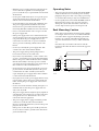
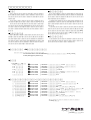
Rack Mounting Caution
If the unit is rack mounted and transported regularly,
for example, when on a tour, we recommend that the
rear of the unit be supported by fitting a pair metal
brackets, one each side. The following drawing pro-
vides the information necessary to make such brack-
ets.
Note that only one bracket is shown here and the
bracket for the other side must be bent in the opposite
direction.
86.5
20.5
3.1
4-
ø
6.5
2-R2
R2
2-R2
R5
t = 1.6
(82.1)
76.2
44.45
31.75
5.9
0
36.5
14.5
7.5
8
0
12
134
200
0

4
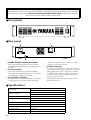
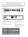
■
Front panel
■
Rear panel
A
POWER ON/OFF switch and indicator
After connecting the PW1D to the CS1D using the
included cable, turn this switch on to supply power to
the CS1D.
B
AC IN connector
Connect the included power cable here. Affix the
power cable plug using the attached screws so that the
cable will not be unplugged accidentally.
C
DC OUTPUT connector
Use this connector to connect the PW1D to the CS1D
to supply power to the CS1D. Turn the cable plug
clockwise to connect the cable, and turn it counter-
clockwise to disconnect the cable.
D
Ground connector
Be sure to ground the unit to avoid the risk of electrical
shock before you insert the power plug into an AC outlet.
This product comes with a 3-pin power cord. If the
ground connector of the AC outlet has already been
grounded, the unit will be grounded effectively by
using the 3-pin power cord.
Grounding the unit is also effective for preventing
hum and other noise.
■
Specifications
Thank you for choosing the PW1D, a power supply unit designed for the CS1D Yamaha control surface.
To install the unit, please select a location with good ventilation. Do not block the front panel or rear panel
or you may restrict fan air flow.
Be sure to use the included special cable
to connect the unit to the
CS1D. Never use other cables to connect these units.
POWER
ON OFF
1
2
4
3
AC IN
DC OUTPUT
CONNECT
DISCON
Power supply
USA and Canada : 120 V, 60 Hz
Others : 230 V, 50 Hz
Power consumption
USA and Canada : 400 W, 450 VA
Others : 400 W
DC Output Voltage CS1D connected : 60V, 12V
DC Output Current CS1D connected, 60V : 5A
CS1D connected, 12V : 0.5A
Dimensions (W
×
H
×
D) 480 mm
×
97.5
mm
×
368.5 mm
Weight 9.6 kg
Operating temperature 10 – 35˚C
Cooling fan speed always fixed
Accessories dedicated connection cable 3.6m
×
1, power cable 2.5 m
×
1

5
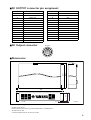
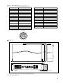
■
DC OUTPUT connector pin assignment
■
DC Output connector
■
Dimensions
• Specifications and appearance are subject to change without notice for improvement.
• For European Model
Purchaser/User information specified in EN55103-1 and EN55103-2.
Inrush Current: 40A
Conformed Environment: E1, E2, E3 and E4.
Pin No. Function Pin No. Function
1
+60 V
15
GND
2
+60 V
16
GND
3
FRAME GND
17
GND
4
+60 V
18
GND
5
+60 V
19
GND
6
+60 V
20
GND
7
+60 V
21
N.C
8
+60 V
22
+12 V
9
+60 V
23
DETECT A
10
+60 V
24
GND
11
GND
25
DETECT B
12
GND
26
CAUTION (+)
13
GND
27
CAUTION (–)
14
GND
DC OUTPUT
123
4567
89
101112
131415161718
1920
2425
27 26
212223
9.5
88
97.5
368.5
355.0
480
unit: mm

YAMAHA CORPORATION
Pro Audio & Digital Musical Instrument Division
P.O. Box 3, Hamamatsu, 430-8651, Japan

J
for

2
!

3
!
86.5
20.5
3.1
4-
ø
6.5
2-R2
R2
2-R2
R5
t = 1.6
(82.1)
76.2
44.45
31.75
5.9
0
36.5
14.5
7.5
8
0
12
134
200
0

4
POWER
ON OFF
1
2
4
3
AC IN
DC OUTPUT
CONNECT
DISCON
1 POWER ON/OFF
2 AC IN
3 DC OUTPUT
4

5
DC OUTPUT
123
4567
89
101112
131415161718
1920
2425
27 26
212223
9.5
88
97.5
368.5
355.0
480

☎
☎
☎
☎
☎
☎
☎
☎
☎
☎
☎
☎
☎
☎
☎
☎
☎
☎
-
 1
1
-
 2
2
-
 3
3
-
 4
4
-
 5
5
-
 6
6
-
 7
7
-
 8
8
-
 9
9
-
 10
10
-
 11
11
-
 12
12


en otros idiomas
- français: Yamaha PW1D Manuel utilisateur
- italiano: Yamaha PW1D Manuale utente
- English: Yamaha PW1D User manual
- Deutsch: Yamaha PW1D Benutzerhandbuch
- русский: Yamaha PW1D Руководство пользователя
- Nederlands: Yamaha PW1D Handleiding
- português: Yamaha PW1D Manual do usuário
- dansk: Yamaha PW1D Brugermanual
- polski: Yamaha PW1D Instrukcja obsługi
- čeština: Yamaha PW1D Uživatelský manuál
- svenska: Yamaha PW1D Användarmanual
- 日本語: Yamaha PW1D ユーザーマニュアル
- Türkçe: Yamaha PW1D Kullanım kılavuzu
- română: Yamaha PW1D Manual de utilizare
Artículos relacionados
-
Yamaha AO8-DA8 Manual de usuario
-
-
-
-
-
-
Yamaha V2 Manual de usuario
-
-
-