
PA series
User's Manual
Antes de utilizar el equipo, lea la sección
“Precauciones de seguridad” de este manual.
Conserve este manual para futuras consultas.
Before operating the device, please read the
“Safety precautions” section of this manual.
Retain this manual for future reference.
PA-500 / PA-900 / PA-1500
PA-2700 / PA-4000

CONTENTS
FRONT PANEL DESCRIPTION
Power switch
Power LED
Level controls
Clip LED
Protection LED
Signal LED
Cooling air grilles
BACK PANEL DESCRIPTION
Speaker outputs
Inputs
Mode switch
Sensitivity mode
Circuit breaker
Power outlet
Cooling air outlet grilles
INSTALLATION
Racking
Input connection
Speaker connection
Mains connection
ON / OFF
Clip LED
Level controls
CONNECTIONS ACCORDING TO OPERATION MODE
SPECIFICATIONS
INTRODUCTION
SAFETY PRECAUTIONS
WARRANTY
DECLARATION OF CONFORMITY
6
6
7
8
9
10
3
4
5
Manual de Usuario / PA series / User’s Manual

PA series
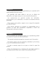
Precauciones de Seguridad
Safety Precautions
Amplificadores de Potencia / Power Amplifiers
Conserve y lea todas estas instrucciones.
Siga todas las advertencias.
El signo de exclamación dentro de un triángulo indica la
existencia de componentes internos cuyo reemplazo puede
afectar a la seguridad.
Keep these instructions.
Heed all warnings. Follow all instructions.
The exclamation point inside an equilateral triangle indicates the
existence of internal components whose substitution may affect
safety.
La posición de encendido está indicada en el interruptor
mediante los correspondientes símbolos normalizados (IEC
60417-1 y IEC 60417-2) y dos LEDs verdes encendidos cerca
del interruptor.
The ON position is indicated in the switch by means of the
corresponding standardized symbols (IEC 60417-1 and IEC
60417-2) and two green LEDs located near the switch.
No existen partes ajustables por el usuario en el interior de este
equipo. Cualquier operación de mantenimiento o reparación
debe ser realizada por personal cualificado. Es necesario el
servicio técnico cuando el aparato se haya dañado de alguna
forma, tal como que haya caído líquido o algún objeto en el
interior del aparato, haya sido expuesto a lluvia o humedad, no
funcione correctamente o haya recibido un golpe.
No user serviceable parts inside. Refer all servicing to qualified
service personnel. Servicing is required when the apparatus has
been damaged in any way, such as power-supply cord or plug is
damaged, liquid has been spilled or objects have fallen into the
apparatus, the apparatus has been exposed to rain or moisture,
does not operate normally or has been dropped.
Si el cable o enchufe de alimentación está dañado, debe ser
sustituido por un cable o conjunto especial a suministrar por el
fabricante o por su servicio postventa.
If the cable or the mains plug are damaged they must be
replaced. Contact the manufacturer to provide you with the
necessary spare parts.
Tenga en cuenta que la tensión nominal de alimentación es el
valor indicado en la etiqueta, con un rango ±10% de ese valor
(según IEC 60065).
Take into account that the nominal AC voltage is the value
shown in the equipment ±10% (according to IEC 60065).
Desconecte este aparato durante tormentas eléctricas,
terremotos o cuando no se vaya a emplear durante largos
periodos.
Unplug this apparatus during ligtning storms, earthquakes or
when unused for long periods of time.
Equipo diseñado para funcionar entre 15ºC y 35ºC con una
humedad relativa máxima del 75%.
Working temperature ranges from 15ºC to 35ºC with a relative
humidity of 75%.
No instale el aparato cerca de ninguna fuente de calor como
radiadores, estufas u otros aparatos que produzcan calor. Debe
instalarse siempre sin bloquear la libre circulación de aire a través
de sus rejillas de ventilación. Tenga en cuenta que el aire circula
de la parte posterior a la frontal.
Do not install near any heat sources such as radiators, heat
registers, stoves or other apparatus that produce heat.
The circulation of air on the fan inlet grills must not be blocked.
The air stream circulates from back to front.
Limpie con un paño seco. No use limpiadores con disolventes. Clean only with a dry cloth. Do not use any solvent based
cleaners.
No exponga este equipo a la lluvia o humedad. No use este
aparato cerca del agua (piscinas y fuentes, por ejemplo). No
exponga el equipo a salpicaduras ni coloque sobre él objetos
que contengan líquidos, tales como vasos y botellas. Equipo IP-
20.
Do not expose this device to rain or moisture. Do not use this
apparatus near water (for example, swimming pools and
fountains). Do not place any objects containing liquids, such as
bottles or glasses, on the top of the unit. Do not splash liquids
on the unit. IP-20 equipment.
Si el aparato es conectado permanentemente, la instalación
eléctrica del edificio debe incorporar un interruptor multipolar con
separación de contacto de al menos 3mm en cada polo.
If the apparatus is connected permanently, the electrical system
of the building must incorporate a multipolar switch with a
separation of contact of at least 3mm in each pole.
Este símbolo indica que el presente producto no puede ser
tratado como residuo doméstico normal, sino que debe
entregarse en el correspondiente punto de recogida de equipos
eléctricos y electrónicos.
This symbol on the product indicates that this product should
not be treated as household waste. Instead it shall be handed
over to the appicable collection point for the recycling of
electrical and electronic equipment.
El cableado exterior conectado a estos terminales requiere de su
instalación por una persona instruida o el uso de cables flexibles
ya preparados.
The connected outer wiring to these terminals requires of its
installation by an instructed person and the use of a flexible the
cable already prepared.
Los signos de rayo cerca de los terminales de salida del
amplificador alertan del riesgo de choque eléctrico en
condiciones normales de uso (terminales peligrosos al tacto). No
toque dichos terminales mientras el amplificador esté encendido.
The lightning and arrowhead symbol near the output terminals of
the amplifier alert of the risk of electric shock in normal
conditions of use (terminal dangerous to the tact). Do not touch
these terminals while the amplifier is working.
El signo del rayo con la punta de flecha, alerta contra la
presencia de voltajes peligrosos no aislados. Para reducir el
riesgo de choque eléctrico, no retire la cubierta.
The lightning and arrowhead symbol warns about the presence
of uninsulated dangerous voltage. To reduce the risk of electric
shock, do not remove the cover.
Aparato de Clase I. Class I device.
3
Manual de Usuario / PA series / User’s Manual

Todos nuestros productos están garantizados por un periodo de 24
meses desde la fecha de compra.
Las garantías sólo serán válidas si son por un defecto de
fabricación y en ningún caso por un uso incorrecto del producto.
Las reparaciones en garantía pueden ser realizadas,
exclusivamente, por el fabricante o el servicio de asistencia técnica
autorizado.
Otros cargos como portes y seguros, son a cargo del comprador
en todos los casos.
Para solicitar reparación en garantía es imprescindible que el
producto no haya sido previamente manipulado e incluir una
fotocopia de la factura de compra.
GARANTÍA
All our products are warrantied against any manufacturing defect
for a period of 2 years from date of purchase.
The warranty excludes damage from incorrect use of the product.
All warranty repairs must be exclusively undertaken by the factory
or any of its authorised service centers.
To claim a warranty repair, do not open or intend to repair the
product.
Return the damaged unit, at shippers risk and freight prepaid, to
the nearest service center with a copy of the purchase invoice.
WARRANTY
4
Manual de Usuario / PA series / User’s Manual

5
Y es conforme a las siguientes Normas Armonizadas Europeas:
In accordance with Harmonized European Norms:
l EN 60065:2014.- Audio, video and similar electronic apparatus. Safety
requirements.
l EN 55032:2012.- Electromagnetic compatibility of multimedia equipment.
Emission requirements.
l EN 55103-2:2009.- Electromagnetic compatibility. Product family
standard for audio, video, audio-visual and entertainment lighting control
apparatus for professional use. Part 2:Immunity.
l EN 50581:2012.- Technical documentation for the assessment of
electrical and electronic products with respect to the restriction of
hazardous substances.
Cumple con los objetivos esenciales de las Directivas:
Abide by essential objectives relating Directives:
l de Baja Tensión (Low Voltage Directive) 2014/35/UE
l de Compatibilidad Electromagnética (EMC) 2014/30/UE
l RoHS 2011/65/UE
l RAEE (WEEE) 2012/19/UE
DECLARACIÓN DE CONFORMIDAD
DECLARATION OF CONFORMITY
DAS Audio Group, S.L.
C/ Islas Baleares, 24 - 46988 - Pol. Fuente del Jarro - Valencia. España
(Spain).
Declara que la serie de amplificadores :PA
Declares that :PA series amplifiers
Manual de Usuario / PA series / User’s Manual

CH 2
0-oo
CH 1
0-oo
CLIP
FLT
SIG
POWER
PA-2700
POW ER AM PL IFI ER
PA-2700
POW ER AM PL IFI ER
INTRODUCTION
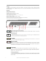
FRONT PANEL DESCRIPTION
General
Thank you for purchasing a DAS power amplifier. It has been built with the most advanced modular
technology, and has been designed through the use of computer-aided design for both the electronic and
mechanical parts.
6
Level controls (C)
Use to set the output level of each channel. The maximum gain is achieved when the
LEVEL rotary potentiometer is turned fully clockwise.
Clip LED (D)
When the output signal distortion of the corresponding channel exceeds 1%, the LED will
light, due to the signal level being is too high.
Protection LED (E)
When circuit protection works, the LED will light, especially when the heat-sinks overheat
or detect the DC voltage in the amplifier. Also, turn on the amplifier and within three seconds,
the amplifier is ready to work, the LED will shine. When startup is complete or the problem is
removed, the LED will extinguish, and resume working normally.
Features
!Efficient linear power supply.
!Dual balanced XLR inputs.
!Speakon output connections.
!Variable speed front to back fan cooling.
!Front located volume controls.
!Input sensitivity switchable between 0.775V and 1.4V.
!Circuit breaker protection.
!Stereo, parallel and bridge operation modes.
!Protection against output short-circuits, overloading and overheating.
!Power, Clip, protection and signal LED indicators.
Signal LED (F)
When there is an input signal, the LED will light. If not, please check the gain
settings. If necessary, the gain can be increased. Check the input connection and signal
audio source. If the Clip LED shines a little or shows no signal, check the output wire
whether it is in short-circuit or not.
Cooling air grilles (G)
Fan cooling permits airflow through the most vital parts of the amplifier. Since the airflow
finds its way out through these grilles, keep them as clean and dust-free as possible to assure
proper cooling.
F
E
D
B
A
Model
G
C
Power switch (A) and power LED (B)
Turns the amplifier on/off when the push button is pressed. When turned on, the power
LED lights blue color.
POWER
FLT
CLIP
SIG
Manual de Usuario / PA series / User’s Manual

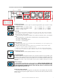
Mode switch (C)
STEREO mode makes the two channels work independently, CH1 input signal by CH1
output, CH 2 input by CH2 output.
BRIDGE mode makes CH1 input signals from the BRIDGE output socket, output
must use CH1 volume control to adjust the volume.
PARALLEL mode makes CH1 input signal by CH1 and CH2 output socket output.
The input socket of Ch2 has no effect. Channel's volume can be adjusted independently.
Speaker outputs (A)
Connecting speakers to each output it is done through Speakon-type connectors whose
pin assignments are:
Channel 1 (stereo and parallel modes) : pin +1 = positive / pin -1 = negative
Channel 2 (stereo and parallel modes) : pin +1 = positive / pin -1 = negative
Channel 1 (bridge mode) : pin +1 = positive / pin +2 = negative
Inputs (B)
CH1 and CH2 are directly connected to the mixer, the input and output connectors
of the respective channel are put together, to provide fixed connection, and no need to
consider the power switch setting.
The nominal input impedance of 20kohms and 10kohms balanced mode in non-balanced
mode.
The pin assignment is according to the standard AES14-1992 (ANSI S4.48-1992):
Pin 1 (XLR) : GND (Ground)
Pin 2 (XLR) : (+) Non-inverted signal
Pin 3 (XLR) : (-) Inverted signal
Sensitivity mode (D)
This switch allows to set the sensitivity between 0.775V or 1.4V.
Cooling air outlet grilles (G)
Fan cooling permits airflow through the most vital parts of the amplifier. Since the airflow
finds its way out through these grilles, keep them as clean and dust-free as possible to assure
proper cooling.
Circuit breaker (E):
When amplifier is overloaded (caused by the small load impedance of the amplifier or the
continuous input signal), the button of the circuit breaker will upspring immediately, and will be
cutoff power automatically to protect the amplifier. You must exclude overload condition, and
then press the button of the circuit breaker, and the power amplifier will resume to normal
operation.
Power outlet (F)
The amplifier is provided with a socket IEC320-C14. When using the amplifier, one
should check whether the selected voltage is correct or not. If the voltage is wrong,
it could damage the amplifier. Please ensure that the device is connected to the
power supply with ground to use.
BACK PANEL DESCRIPTION
7
22 0V ~50 /6 0H z
INP U T C H 1
MO D E
BRIDGE
PA R A L L E L
STEREO
SE N SI T I V I T Y
1. 4V
0. 775V
RE S E T
CH 2
CH 1CH 1
CH 1
CH 2 CH 2
RES E T
SE NSI T IV I TY
MO DE
1.4 V
0.7 75V
BR IDG E
ST ERE O
INP U T
CH2
INP U T
C H 1
CAU TION ATTEN TION
RISK OF ELECTRIC SHOCK
DO NOT OPEN
DANGER D’ELECTROCUTION
NE PAS OUVRIR
CH 2 CH 1
LO CK
OUT P U T
LO CK
BR IDG E
OU T P U T
CH 2 CH 1
LO CK LO CK
F
E
D
B
A
Model
G
C
Professional Audio Amplifier PA-2700
Imported by DAS Audio Group, S.L. - www.dasaudio.com
Made in China
Consumptions:
PA-500: 2.8 A @ 230Vac
PA-900: 4.5 A @ 230Vac
PA-1500: 7.5 A @ 230Vac
PA-2700: 9.2 A @ 230Vac
PA-4000: 15.2 A @ 230Vac
Manual de Usuario / PA series / User’s Manual

Speaker connection
Connect speakers at one or two output
Speakon connectors. See the rear panel
instructions.
Speakon connectors offer quick connection for
portable applications. To enable a Speakon
connection, plug the male connector into the
outlet and rotate it clockwise. It will then lock into
place and be ready for use.
Racking
All amplifiers are 19-inch rack mount width and
are 2U DIN in height.
Four front-panel mounting holes are provided
for use with M5 or M6 or 1/4” screws. To avoid
bending the chassis in rack mounting applications
where the rack will be transported, mount the
amplifiers to the back of the rack using the rear
mounting holes. Alternatively, place the bottom
amplifier against the base of the rack and pile the
amplifiers with no clearance in between.
A fan cools the aluminum heat sinks from front
to back.
Fan cooling permits airflow through the most
vital parts of the amplifier.
When mounting the unit onto a 19-inch rack, a
rack cooling system is not required, since the air is
exhausted out through the front grille.
However, the rack must not be sealed, and it
should at least have a large enough ventilation
grille to allow air into the rack.
Input connection
A balanced connection is recommended with
XLR connectors, but an unbalanced connection
can also be used.
Mains connection
Should check whether the selected voltage is
correct or not. If the voltage is wrong, it could
damage the amplifier.
The230 V AC version has a nominal voltage
plus minus 10%, i.e., the amplifier can operate
from 207 V to 253 V AC.
Similarly, the 115 V AC version has a nominal
voltage plus minus 10%, i.e., the amplifier can
operate from 103 V to 127 V AC.
In both cases the operating voltage will be
indicated on the back panel.
INSTALLATION
8
ON / OFF
The main power switch is a push button that
turns the amplifier on/off.
When the amplifier turns on, the power LED
and protection LED are illuminated. After a few
seconds, when the start is finished the
PROTECTION LED will go out and the amplifier
will be ready for use.
To turn the amplifier off, push the button. At
that moment the main power supply voltage and
the secondary power supply voltage will turn off
internally.
Switch your sound system on from back to
front. Thus, switch on the amplifiers last on your
sound system. Switch sound sources (CDs,
turntables) first, then your mixer, then your
processors and crossovers and finally the
amplifiers. If you have more than one amplifier,
switch them on sequentially, one at a time or use a
sequencer.
Follow the reverse order when switching off,
and switch off the amplifiers before any other
element on your sound system.
Clip LED
The clip LED should never be on continuously.
This will distort the signal and may damage the
speakers. In fact, severe clipping is an easy way of
burning a speaker's voice coil.
The amplifiers feature an automatic limiting
system that impedes prolonged saturation, but the
dynamic nature of music signals stops it from
being a brick wall protection. Thus at most, the
clip light could be lit occasionally.
Level controls
The level rotary potentiometer is used for
changing the input gain. Although related to output
power, it is not a direct representation of it. Thus,
we can have maximum output power with the gain
at mid position. Similarly, we may have the gain
controls at maximum and not have maximum
output if our source signal is not strong enough.
One way to use the volume controls is to set
them such that when the mixer's faders are at
their maximum level, we are just below clipping
level on the amplifier or clipping very occasionally.
Manual de Usuario / PA series / User’s Manual

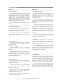
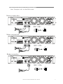
CONNECTIONS ACCORDING TO OPERATION MODE
9
CH 2
CH 1CH 1
CH 1
CH 2 C H 2
RES E T
SE NSI T IV I TY
MO D E
1.4 V
0.7 75V
BR IDG E
ST ERE O
INP U T
CH2
INP U T
C H 1
CAU TION ATT ENTI ON
RISK OF ELECTRIC SHOCK
DO NOT OPEN
DANGER D’ELECTROCUTION
NE PAS OUVRIR
CH 2 CH 1
LO C K
OUT P U T
LO C K
BR IDG E
CH 2
CH 1CH 1
CH 1
CH 2 C H 2
RES E T
SE NSI T IV I TY
MO D E
1.4 V
0.7 75V
BR IDG E
ST ERE O
INP U T
CH2
INP U T
C H 1
CAU TION ATT ENTI ON
RISK OF ELECTRIC SHOCK
DO NOT OPEN
DANGER D’ELECTROCUTION
NE PAS OUVRIR
CH 2 CH 1
LO C K
OUT P U T
LO C K
BR IDG E
CH 2
CH 1CH 1
CH 1
CH 2 C H 2
RES E T
SE NSI T IV I TY
MO D E
1.4 V
0.7 75V
BR IDG E
ST ERE O
INP U T
CH2
INP U T
C H 1
CAU TION ATT ENTI ON
RISK OF ELECTRIC SHOCK
DO NOT OPEN
DANGER D’ELECTROCUTION
NE PAS OUVRIR
CH 2 CH 1
LO C K
OUT P U T
LO C K
BR IDG E
Stereo connection
Bridge connection
Mono connection
A
B
2+
1-
2-
1+
- to PIN 1 -
+ to PIN 1 +
2+
1-
2-
1+
- to PIN 2+
+ to PIN 1 +
Horn:
Horn:
Horn:
Horn:
2+
1-
2-
1+
- to PIN 1 -
+ to PIN 1 +
Horn:
Horn:
A
+
-
B
+
-
A
A
+
-
A
A
+
-
B
+
-
Note: Examples with the PA-2700 model:
Professional Audio Amplifier PA-2700
Imported by DAS Audio Group, S.L. - www.dasaudio.com
Made in China
Professional Audio Amplifier PA-2700
Imported by DAS Audio Group, S.L. - www.dasaudio.com
Made in China
Professional Audio Amplifier PA-2700
Imported by DAS Audio Group, S.L. - www.dasaudio.com
Made in China
Manual de Usuario / PA series / User’s Manual

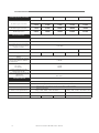
SPECIFICATIONS
10
Frequency Response(at 1 Watt)
Total Harmonic Distortion(THD)
Intermodulation Distortion60Hz
and 7KHz at 4:1from full rated
output to -30dB
Slew Rate
Voltage Gain
Damping Factor(8ohms)10Hz-
400Hz
Signal-to-Noise Ratio (below
rated power,20Hz to 20kHz.
A-weighted)
Crosstalk(below rated power)
At 1kHz
At 20kHz
Input Sensitivity for full
rated power at 8Ω
Input impedance(nominal)
Balanced
Unbalanced
20Hz-20KHz,+0-1dB
<0.5%,20Hz-20kHz
=/<0.35%
>10V/us
>200
>100dB
-75dB
-58dB
0.775V or 1.4V
20K ohms
10k ohms
PA-500 PA-900 PA-1500 PA-2700
27dB 31dB 33dB 36dB
1kHz(HIA)with0.5%THD
4Ω stereo(per channel)
8Ω bridge mono
250W
150W
500W
450W
350W
900W
750W
500W
1500W
1350W
1000W
2700W
Rated power /model
Performance
Construction
Ventilation
Protection
Cooling
Power cord specification
Chassis size( unit mm)
Net weight
Protection against short circuits, no-load, on/off muting, RF interference.
Flow-through ventilation from front to back
Internal heat sinks with forced air. Fan cooled, speed regulated,
thermal protection
10.1kg 12.7kg 13.5kg 19.5kg
482x227x88 482x294x88
8Ω stereo(per channel)
PA-4000
37dB
2100W
1400W
4250W
>20V/us
Plug Wire::16A,250V 3x1.5mm
2
Plug Wire::10A,250V 3x1.0mm
2
Manual de Usuario / PA series / User’s Manual

UM_PA_03_EN
www.dasaudio.com
DAS Audio of America, INC.
6900 NW 52th Street
Miami, FL. 33166 - U.S.A.
TOLL FREE: 1 888 DAS 4 USA
DAS Audio Asia PTE. LTD.
3 Temasek Avenue, Centennial
Tower #34-36
Singapore 039190
Tel. +65 6549 7760
DAS Audio Group, S.L.
C/. Islas Baleares, 24
46988 Fuente del Jarro
Valencia, SPAIN
Tel. +34 96 134 0860
DAS do Brasil LTDA.
Rua Dos Andradas, 382 SL
Santa Efigênia, São Paulo
Brasil. CEP: 01208-000
Tel. +551133330764
-
 1
1
-
 2
2
-
 3
3
-
 4
4
-
 5
5
-
 6
6
-
 7
7
-
 8
8
-
 9
9
-
 10
10
-
 11
11


DAS PA-1500 Manual de usuario
- Categoría
- Amplificadores de audio
- Tipo
- Manual de usuario
en otros idiomas
- English: DAS PA-1500 User manual
Artículos relacionados
Otros documentos
-
D.A.S. M-14:2 Manual de usuario
-
HH Electronics M Series Professional Power Amplifier Manual de usuario
-
Ecler XPA SERIES Manual de usuario
-
-
Akiyama AMD-400 Manual de usuario
-
BEGLEC CTWO 800 Manual de usuario
-
Harman MA12000i Manual de usuario
-
Crown MA 5000i El manual del propietario
-