Fortis 842120c Instrucciones de operación
- Tipo
- Instrucciones de operación

8 4 2 1 2 0 C S C A L A
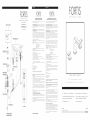
8 - 1 5 ” W i d e s p r e a d L a v a t o r y
G r u p o l a v a b o d e 3 o r i f i c i o s - d e 8 ” 1 5 ”
For information such as installation or
care and warranty for this product, please
contact your local Fortis distributor.
www.fortisfaucet.com
Para informacion sobre la instalación, o
cuidar el producto y garantia, por favor
llama a su distribuidor local de Fortis.
www.fortisfaucet.com
12-02-2016
Copyright © 2009, Fortis
842120C
English Español
Fortis 877 55 FORTIS - (36784) ain RDM
ewfield NJ 08344N ,
www.fortisfaucet.com
support@fortisfaucet.com
for technical support call
1-877-280-5940
English Español
LIMITED LIFETIME WARRANTY
FOR RESIDENTIAL PRODUCTS
FORTIS provides the following warranties for its products to the original
purchaser in a residential application.
MECHANICAL WARRANTY: FORTIS provides a Limited Lifetime Warranty
to all mechanical parts to be free from all manufacturing defects in materials
and workmanship under normal use for as long as the original purchaser
owns their home.
FINISH WARRANTY: FORTIS provides a Limited Lifetime Warranty on all
Fortis products to the original purchaser against manufacturing defects in
materials and workmanship.
In the event of any defect in the product breaches the foregoing warranties,
FORTIS, at its option, will replace any part or finish that proves to be
defective in material and/or workmanship, under normal installation, use
and service. Repair or replacement of the product is the exclusive remedy.
For any remedy under this warranty, FORTIS, is to be notified describing the
problem. In order to notify FORTIS and receive assistance or service under
this warranty, the original purchaser may:
1. Contact by Phone: For a consumer service representative, call 1-877-
280-5940 2. Contact by Mail: Write consumer service department to the below
address: FORTIS, Inc.,
Customer Service Department
1571 North Main Road
Newfield, NJ 08344
(877) 280-5940
3. Contact by Email: Email Fortis customer service: customerservice@
fortisfaucet.com
4. Contact your Distributor: Notify the location or distributor from which the
product was purchased.
Upon contacting FORTIS, you will need to provide:
a. FORTIS product model number
b. A description of the problem
c. Your contact information (Name, Address, Phone Number)
d. Approximate Date of Purchase In addition to the information above, to obtain a warranty repair or
replacement, you will need to provide:
1. The faulty part or product (carefully packed)
2. Proof-of-purchase (original sales receipt) from the original consumer
purchaser
FORTIS, Inc.,
Customer Service Department
1571 North Main Road
Newfield, NJ 08344
(877) 280-5940
Please allow 7 to 14 business days warranty processing.
EXCLUSIONS: This warranty does NOT cover and FORTIS will NOT
pay for:
1. Conditions, malfunctions or damage not resulting from defects in material
or workmanship
2. Conditions, malfunctions or damage resulting from any of the following:
a. Normal wear and tear, improper installation, improper maintenance,
misuse, abuse, negligence, accident or alteration
b. The use of abrasive or caustic cleaning agents or “no-rinse” cleaning
products, or the use of the product in any manner contrary to the product
instructions
c. Conditions in the home such as excessive water pressure or corrosion
3. Labor and other expenses related to disconnection, deinstallation, or
return of the product for warranty service (including but not limited to proper
packaging and shipping costs) or for installation or reinstallation of the
product
4. Accessories, connected to materials and products, or related products not
manufactured by FORTIS.
5. Any FORTIS product sold for display purposes.
WARRANTY FOR COMMERCIAL APPLICATIONS:
If the FORTIS product is installed in a commercial application, the above
mechanical warranty shall be limited for a period of (10) years and the
above finish warranty shall be limited for a period of (5) years from the date
of the purchase of the product.
Repair or replacement parts are warranted only for the period remaining
under the initial warranty. The same exclusions apply as above residential
application policy.
GARANTÍA LIMITADA DE POR VIDA
PARA PRODUCTOS DE USO RESIDENCIAL
FORTIS ofrece al comprador original las siguientes garantías para sus
productos utilizados para instalaciones residenciales.
GARANTÍA PARTES MECÁNICAS: FORTIS ofrece para todos los
componentes mecánicos una Garantía Limitada de por vida que cubre los
defectos de fabricación en los materiales y elaboración, en condiciones de
uso normales, hasta que el comprador original sea propietario del inmueble
donde se instala el producto.
GARANTÍA ACABADOS: FORTIS ofrece al comprador original para todos
los productos FORTIS una Garantía Limitada de por vida que cubre los
defectos de fabricación en los materiales y la elaboración.
En caso de que un producto no fuera conforme a los parámetros de las
mencionadas garantías debido a algún defecto, FORTIS, a su exclusiva
discreción, sustituirá el componente o el acabado defectuoso en el
material y/o la elaboración en normales condiciones de instalación,
uso y mantenimiento. La única solución admitida será la reparación o la
sustitución del producto.
Para hacer valer cualquier tipo de cobertura prevista por la garantía el
usuario deberá enviar la solicitud a FORTIS junto con una descripción
completa del problema. Para notificar a FORTIS y recibir asistencia o un
servicio en conformidad a la presente garantía, el comprador original
podrá:
1. Llamar por teléfono: para ponerse en contacto con un representante del
servicio de atención al cliente al número 1-877-280-5940
2. Por correo: Escribir a la oficina del servicio de atención al cliente a la
siguiente dirección: FORTIS, Inc.,
Customer Service Department
1571 North Main Road
Newfield, NJ 08344
(877) 280-5940
3. Por email: Email del servicio de atención al cliente FORTIS:
customerservice@fortisfaucet.com
4. Contactar a nuestro distribuidor: Comunicar el lugar o el distribuidor
donde ha sido comprado el producto.
Después de haberse puesto en contacto con FORTIS, deberán indicar:
a. El número del modelo del producto FORTIS
b. Una descripción del problema
c. Las informaciones para contactarles (nombre, dirección, número de
teléfono)
d. Fecha de compra aproximada
Para poder recibir asistencia para la reparación o sustitución en garantía,
además de las informaciones anteriormente mencionadas, deberán enviar
lo siguiente:
1. El componente o producto defectuoso (cuidadosamente embalado)
2. El comprobante de compra (recibo de compra original) que el comprador
original del producto posee.
FORTIS, Inc.,
Customer Service Department
1571 North Main Road
Newfield, NJ 08344
(877) 280-5940
Para la elaboración de la solicitud de aplicación de la garantía serán
necesarios de 7 a 14 días laborales.
EXCEPCIONES: La presente garantía NO cubre y FORTIS NO pagará
por:
1. Las condiciones, los malfuncionamientos o los daños que no sean debidos
a defectos de material o elaboración
2. Las condiciones, los malfuncionamientos o los daños debidos a uno de los
siguientes casos:
a. Normal desgaste, instalación incorrecta, mantenimiento incorrecto, uso
impropio, abuso, negligencia, accidente o alteración
b. Uso de agentes abrasivos o productos de limpieza corrosivos o que no
necesitan enjuague, o uso impropio del producto contrario a las indicaciones
c. Condiciones del inmueble producidas por excesiva presión del agua o
corrosión
3. Mano de obra y otros gastos relativos a la desconexión, desmontaje
o restitución del producto por servicios de garantía (incluso el embalaje
adecuado y los costos de expedición) o por la instalación o el desmontaje
del producto.
4. Accesorios, relacionados con los materiales y productos, o relativos a
productos no fabricados por FORTIS.
5. Los productos FORTIS vendidos exclusivamente con fines de exposición.
GARANTÍA PARA USOS COMERCIALES:
En caso de que el producto FORTIS sea instalado en una unidad comercial,
la garantía para las partes mecánicas anteriormente indicada será limitada a
un período de (10) años y la garantía para los acabados será limitada a un
período de (5) años desde la fecha de compra del producto.
Las reparaciones y las piezas de repuesto están cubiertas por la garantía
sólo por el período restante de la garantía original. La misma excepción es
válida, como se indica anteriormente, para las normas aplicables al uso en
unidades residenciales.
AC84IST214RQSRNUF
53CR945TSR

EspañolEnglish
En caso de presiones de trabajo superiores a 5 bar
(~75 psi) se recomienda utilizar un reductor de presión.
Antes de realizar el montaje, se recomienda purgar
las tuberías de agua caliente y fría para evitar que la
suciedad y pequeñas impuridades puedan comprometer
el funcionamiento del grifo.
FIG.01 INSTALACIÓN DE LAS COLUMNAS
Colocar el o-ring de base (1.D) debajoo de la base
rectangular (1.C). Insertar desde arriba, en el agujero
del sanitario, con la base interpuesta (1.B), la columna
pre-ensamblada (1.A) y el tubo flexible (1.B) (prestando
atención a introducir el bloque con flexible rojo en el
agujero de la izquierda, el que tiene flexible azul en
el agujero de la derecha). Colocar, desde abajo del
sanitario, la junta (1.E) y la brida perfilada (1.F),después
atornillar la contratuerca (1.G) hasta llegar a tope
prestando atención a la posición de la base rectangular.
FIG.01 INSTALACIÓN DE LA BOQUILLA DE
DISTRIBUCIÓN
Insertar la base rectangular (1.J) en el vástago de rosca
de la boquilla (1.H) y bloquearla con los tornillos (1.K).
Colocar el o-ring de base (1.L) debajo de la base
rectangular (1.J) e introducir el bloque desde arriba en
el agujero central del sanitario.
Colocar la junta (1.M) y la brida perfilada (1.N),
después atornillar la contratuerca (1.O) hasta llegar a
tope.
FIG.02 INSTALACIÓN DE LAS MANILLAS
Insertar la manilla (2.A) en el racor escariado del
bloque de la columna ((2.D) hasta el tope, manteniendo
la posición correcta. A continuación apretar la espiga
(2.B), en la manilla (2.A) insertando la plaqueta (2.C).
FIG.02 CONEXIONES
Atornillar la cruceta (2.H) en el vástago de la rosca de
la boquilla (2.F), insertando la junta (2.G).
Atornillar los flexibles (2.E) en los agujeros de la
columna de la manilla y atornillarlos a continuación en
la crueceta (2.H).
FIG.03 MONTAJE DE LA DESCARGA
Para realizar el montaje de la descarga, insertar la
junta (3 C) en la pileta (3.B) e insertar esta última en
el agujero de descarga del sanitario. Colocar la junta
(3.D) en el alojamiento correspondiente del cuerpo de
descarga (3.E) y atornillar este último hasta el bloqueo
In the case of operating pressures greater than 5 bar
(~75 psi) the use of a pressure reducer is recommended.
Before assembling it is advisable to clean hot and cold
water pipework to prevent dirt and small impurities from
compromising faucet operation.
FIG.01 STEM INSTALLATION
Place the base O-ring (1.D) below the rectangular base
(1.C). Insert the ready-assembled stem (1.A) and hose
pipe (1.B) into the gap of the fixture from above (taking
care to insert the red hose unit into the left gap and the
blue hose unit into the right gap). Position the seal (1.E)
and the shaped flange (1.F) from below the fixture, then
tighten the locking nut (1.G) fully home, taking care not
to damage the rectangular base.
FIG.01 SPOUT INSTALLATION
Insert the rectangular base (1.J) into the threaded stem
of the spout (1.H) and lock it in position with the screws
(1.K). Place the base O-ring (1.L) below the rectangular
base (1.J) and insert the unit into the central gap of
the fixture from above. Position the seal (1.M) and the
shaped flange (1.N), and tighten the locking nut (1.O)
until it goes.
FIG.02 HANDLE INSTALLATION
Place the handle (2.A) on the broached fitting of the stem
unit (2.D) fully home, keeping the correct position.
Then tighten the grub screw (2.B) in the handle (2.A) and
insert the plate (2.C).
FIG.02 CONNECTIONS
Screw the crosspiece (2.H) to the threaded stem of the
spout (2.F), by inserting the seal (2.G). Secure the hose
pipes (2.E) to the gaps in the handle stems and tighten
them to the crosspiece (2.H).
FIG.03 DRAIN ASSEMBLY
To assemble the drain, fit the seal (3.C) on the outlet
(3.B) and then insert it into the drain hole of the fixture.
Position the seal (3.D) in the slot provided in the drain
body (3.E) and tighten it until it goes (if necessary also
insert some silicone between the outlet and ceramic).
Secure the drain pipe (3.G) using the locking nut (3.H),
by inserting the seal (3.F) between the pipe and the
drain body. Screw the cap (3.A) onto the outlet (3.B).
Turn the faucet on and check the mixer operates correctly
and the seal between parts is perfect.
(si es necesario utilizar silicona entre la cerámica y
la pileta). Fijar por medio de la contratuerca (3.H) el
tubo de descarga (3.G), insertando entre el tubo y el
cuerpo de descarga la junta (3.F). Atornillar entonces el
tapón (3.A) en la pileta (3.B). Abrir el agua y verificar
el funcionamiento correcto del mezclador, así como la
hermeticidad perfecta de todas sus partes.
MANTENIMIENTO Y RECOMENDACIONES
TÉCNICAS PRÁCTICAS
FIG.04 SUSTITUCIÓN DE LA ROSCA
Si fuera necesario sustituir la rosca (4.L), en primer
lugar es necesario aflojar la contratuerca (4.M) Extrar
la plaqueta (4.C) de la manilla (4.A) destornillando
la espiga (4.B). Extraer entonces la manilla (4.A).
Destornillar el tornillo (4.D), extraer el racor escariado
(4.E) y el anillo anti-frotamiento (4.F). Destornillar el
racor (4.G) y extraer la base (4.H) y la junta (4.I).
Destornillar la rosca (4.L) con la llave correspondiente,
sostituirlo si es necesario y asegurarse de que las
superficies de hermeticidad de las juntas están limpias.
Volver a montar efectuando las operaciones inversas,
prestando atención de colocar correctamente la junta
(4.I) debajo de la base (4.H). Es conveniente limpiar
periódicamente el dispositivo de aireación para evitar
la acumulación de residuos y cal que, al pasar el
tiempo, originan una disminución gradual del caudal.
Destornillar el dispositvo de aireación (4.O) y limpiarlo
de las impurezas. Al volver a montarlo interponer
siempre la junta (4.N).
Fig.05 DESPLAZAMIENTO DE LAS MANILLAS
Operando en las manillas (5.A) y (5.B) es posible
regular el flujo de temperatura del agua, girando
la manilla (5.B) se regula el caudal de agua fría,
desplazando la manilla (5.A), por el contrario se regula
el agua caliente. Mientras más se alejan de la posición
de cierre, más elevado es el caudal.
MANTENIMIENTO DE LAS SUPERFICIES
Durante la limpieza, la superficie del grifo debe estar
fría (el calor acelera el deterioro de la superficie misma)
Comprobar que los productos de limpieza no contienen
ácidos o sustancias corrosivas. El grifo debe secarse
a diario con un paño suave. Evitar absolutamente
estropajos, esponjas abrasivas o similares. Justo después
de la limpieza, enjuagar bien los restos de detergente
con agua fría. Los daños a los grifos, consiguientes a un
tratamiento inapropiado, están excluidos de la garantía.
MAINTENANCE AND TECHINICAL HINTS AND TIPS
FIG.04 SCREW-DOWN VALVE REPLACEMENT
If it becomes necessary to replace the screw-down valve
(4.L), unscrew the locking nut (4.M), remove the plate
(4.C) from the handle (4.A) by unscrewing the grub
screw (4.B). Then remove the handle (4.A). Loosen the
screw (4.D), pull out the broached fitting (4.E) and the
anti-friction ring (4.F). Unscrew the fitting (4.G) and pull
out the strip (4.H) and the seal (4.I). Unscrew the screw-
down valve (4.L), using the wrench provided, replace it
if necessary and ensure seal surfaces are clean. Remount
in reverse order, making sure the seal (4.I) is positioned
correctly below the strip (4.H). It is good practice to
clean the aerator regularly to prevent the accumulation of
dirt and limescale, which can cause a gradual decrease
in flow rate over time. Loosen the aerator (4.O) and
clean it to remove any impurities. Always insert the seal
(4.N) in between during reassembly.
Fig.05 HANDLE OPERATION
Water flow and temperature can be regulated using the
handles (5.A & 5.B): turn handle 5.B to regulate cold
water flow and 5.A to regulate hot water flow. Flow
rate is increased by turning the handles further from the
OFF position.
LOOKING AFTER THE SURFACE
The surface of the faucet should be cold during cleaning
(heat accelerates wear and tear on the surface itself).
Ensure cleaning products do not contain acids or
corrosive substances. The faucet should be dried daily
with a soft cloth. Avoid using steel wool, abrasive
sponges or similar items. Immediately after cleaning
rinse detergent off with cold water. Damage to faucets
resulting from inappropriate treatment is not covered by
the warranty.
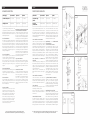
Water Supply Recommended Maximum Minimum
Hot Water Temperature 65 C° (~150F) 80 C° (~175F) 15 C° (~60F)
Working Pressure 3 BAR (~45PSI) 5 BAR (~75PSI) 0.5 BAR (~7PSI)
Alimentación Recomendada Máxima Mínima
Temperatura agua
caliente
65 C° (~150F) 80 C° (~175F) 15 C° (~60F)
Presión de
funcionamiento
3 BARES (~45PSI) 5 BARES (~75PSI) 0.5 BARES (~7PSI)
INSTALLATION INSTRUCTIONS INSTRUCCIONES DE INSTALACIÓN
FIG. 01
FIG. 04
FIG. 02
FIG. 03
FIG. 05
Based on its policy of steady development Fortis reserves the right to change the characteristics
of the products without notice and therefore the images and data contained in this catalogue may vary.
Por su política de continuo desarrollo, Fortis se reserva el derecho de modificar las características de los productos sin ningún aviso
previo; por tanto, las imágenes y los datos contenidos en el presente catálogo deben considerarse a título indicativo.
-
 1
1
-
 2
2


Fortis 842120c Instrucciones de operación
- Tipo
- Instrucciones de operación
En otros idiomas
Documentos relacionados
-
Fortis 942110c Maintenance & Installation Instructions
-
-
-
-
-
-
-
-
-