Dali E-50 Manual de usuario
- Categoría
- Altavoces de coche
- Tipo
- Manual de usuario

DALI PHANTOM E and K Series
MANUAL
ENGLISH - DEUTSCH - 零部件 - FRANÇAIS - ESPAÑOL
E-50
E-60
E-60 S
E-80
K-60
K-60 LP
K-80

2
FIGURE 1A
FIGURE 1C
FIGURE 1B
X X
ITEM E-series K-series
Speakers 1 pc 1 pc
Grilles 1 pc 1 pc
Cut-out template 1 pc 1 pc
DALI logo badge 1 pc -
Owner’s manual 1 pc 1 pc
TABLE 1

3
UK DE CN FR ES
FIGURE 5 FIGURE 6 FIGURE 6B
FIGURE 7 FIGURE 7B
FIGURE 2 FIGURE 3 FIGURE 4
FIGURE 8 FIGURE 9 FIGURE 10
-165
-150
-135
-120
+165
+150
+
F
H
R
l
a
m
r
o
N
+
F
H
L
l
a
m
r
o
N
-165
+165
+150
+
F
H
R
l
a
m
r
o
N
+
F
H
L
l
a
m
r
o
N
-15
-30
-45
-60
-75
-90
+90
+75
+60
+45
+30
+15
-165
-150
-135
-120
-105
+165
+150
+135
+120
+105
+
F
H
R
l
a
m
r
o
N
+
F
H
L
l
a
m
r
o
N
LR
-15
-30
-45
-60
-75
-90
+75
+60
+45
+30
+15
-165
-150
-135
-120
-105
+165
+150
+135
+120
+105
.
b
i
r
t
s
i
D
.
s
u
c
o
F
t
l
i
T
+
F
H
l
a
m
r
o
N
DALI PHANTOM
-15
-30
-45
-60
-75
-90
+90
+75
+60
+45
+30
+15
-165
-150
-135
-120
-105
+165
+150
+135
+120
+105
.
b
i
r
t
s
i
D
.
s
u
c
o
F
t
l
i
T
+
F
H
l
a
m
r
o
N
DALI PHANTOM
-15
-30
-45
-60
-75
-90
+90
+75
+60
+45
+30
+15
-165
-150
-135
-120
-105
+165
+150
+135
+120
+105
.
b
i
r
t
s
i
D
.
s
u
c
o
F
t
l
i
T
+
F
H
l
a
m
r
o
N
DALI PHANTOM
FIGURE 6C
-
9
0
-
1
2
0
-
1
5
0
+
1
5
0
+
1
2
0
-
6
0
-
3
0
+
3
0
+
6
0
N
o
r
m
.
H
i
g
h
+
0
-
3
0
+
3
0
+
6
0
N
o
r
m
.
H
i
g
h
+

4
PHANTOM E-50 PHANTOM E-60 PHANTOM E-60 S PHANTOM E-80
Frequency range 58 - 25,000 Hz ±3 dB 52 - 25,000 Hz ±3 dB 57 - 25,000 Hz ±3 dB 49 - 25,000 Hz ±3 dB
Sensitivi 87 dB @ 1 m for 2.83 V 88 dB @ 1 m for 2.83 V 90 dB @ 1 m for 2.83 V (both
channels) 89.5 dB @ 1 m for 2.83 V
Nominal impedance 8 ohm 8 ohm 8 + 8 ohm 6 ohm
Maximum SPL 104 dB 105 dB 105 dB 107 dB
Crossover frequency 3,600 Hz 3,300 Hz 2,600 Hz 3,200 Hz
Crossover principle 2-way 2-way 2+2-way 2-way
Recommended amplifier power 40 - 120 Wa 30 - 120 Wa 2 x 20 - 80 Wa 30 - 150 Wa
High frequency driver 1 x 28 mm so dome 1 x 28 mm so dome 2 x 20 mm so dome 1 x 28 mm so dome
High frequency diaphragm So woven fabric So woven fabric So woven fabric So woven fabric
Low/Mid frequency driver 1 x 5¼ inch 1 x 6½ inch 1 x 6½ inch dual voice coil 1 x 8 inch
Low/Mid frequency diaphragm Polypropylene Polypropylene Polypropylene Polypropylene
Connection input Single wire Single wire 2 x Single wire Single wire
Enclosure pe Open back Open back Open back Open back
Other features Normal/HF Tilt
Focus/Distributed
Normal/HF Tilt
Focus/Distributed
Normal/HF Tilt
Focus/Distributed
Normal/HF Tilt
Focus/Distributed
Installation location In-ceiling/In-wall In-ceiling/In-wall In-ceiling/In-wall In-ceiling/In-wall
Recommended placement Ceiling/Front/Centre/Surround Ceiling/Front/Centre/Surround Ceiling/Front/Centre/Surround Ceiling/Front/Centre/Surround
Outer dimensions incl. grille
(H x W x D)
Ø 230 x 100 mm
Ø 9.1 x 3.9 inches
Ø 258 x 100 mm
Ø 10.2 x 3.9 inches
Ø 258 x 112 mm
Ø 10.2 x 4.4 inches
Ø 294 x 118 mm
Ø 11.6 x 4.6 inches
Outer dimensions excl. grille
(H x W x D)
Ø 214 x 95 mm
Ø 8.4 x 3.7 inches
Ø 242 x 95 mm
Ø 9.5 x 3.7 inches
Ø 242 x 106 mm
Ø 9.5 x 4.2 inches
Ø 278 x 113 mm
Ø 11.0 x 4.5 inches
Cut-out dimensions Ø 197 mm
Ø 7.8 inches
Ø 225 mm
Ø 8.9 inches
Ø 225 mm
Ø 8.9 inches
Ø 261 mm
Ø 10.3 inches
Mounting depth 95 mm
3.7 inches
95 mm
3.7 inches
101 mm
4 inches
109 mm
4.3 inches
Recommended rear volume
(backbox) 5 - 35 litres 5 - 50 litres 5 - 35 litres 10 - 100 litres
Optimum rear volume 12 litres 15 litres 15 litres 30 litres
Ceiling/wall thickness
(total dog-leg span)
10 - 70 mm
0.4 - 2.8 inches
10 - 70 mm
0.4 - 2.8 inches
10 - 70 mm
0.4 - 2.8 inches
10 - 70 mm
0.4 - 2.8 inches
Weight incl.grille 2 kg
4.40 lb
2 kg
4.40 lb
2 kg
4.40 lb
2.50 kg
5.51 lb
Shipping weight 2.50 kg
5.51 lb
3 kg
6.60 lb
3 kg
6.60 lb
3.50 kg
7.71 lb
Finish White White White White
Accessories
Manual
Cut-out template
Front grille
Logo badge
Manual
Cut-out template
Front grille
Logo badge
Manual
Cut-out template
Front grille
Logo badge
Manual
Cut-out template
Front grille
Logo badge
Optional accessories
E Series grille (square)
Pre-construction Kit
PHANTOM UNIVERSAL 25
backbox
E series grille (square)
K series grille (white or black)
Pre-construction Kit
PHANTOM UNIVERSAL 25
backbox
E Series grille (square)
K Series grille (white or black)
Pre-construction Kit
PHANTOM UNIVERSAL 25 backbox
E series grille (square)
K series grille (white or black)
Pre-construction Kit
PHANTOM UNIVERSAL 25
backbox
TABLE 2 - PHANTOM E Series TECHNICAL SPECIFICATIONS
All technical specifications are subject to change without notice.


6
CONTENTS
1.0 OWNER’S MANUAL 7
2.0 SAFETY PRECAUTIONS 7
3.0 UNPACKING/PARTS LIST 7
4.0 DALI PHANTOM E- AND K-SERIES – SETUP AND POSITIONING 7
5.0 CUT-OUT TEMPLATE 10
6.0 INSTALLATION 11
7.0 RUNNING-IN 11
8.0 MAGNETIC SHIELDING 12
9.0 MAINTENANCE 12
10.0 ENVIRONMENTAL INFORMATION AND DISPOSAL 12
11.0 TECHNICAL SPECIFICATIONS 12

7
UK DE CN FR ES
1.0 OWNER’S MANUAL
Congratulations on your new speakers. Please read this manual carefully before
you unpack and install your new speakers to get the most out of your purchase. You
can find more information on our website: www.dali-speakers.com or by contacting
your authorized DALI dealer.
2.0 SAFETY PRECAUTIONS
• Always follow all safe guidelines.
• DALI PHANTOM E- and K-series are intended for indoor use.
• The speaker must only be used indoors and never in extreme hot or cold
temperatures.
• DALI PHANTOM E- and K-series must not be exposed to direct sunlight.
• Power o the amplifier when connecting the loudspeaker cables to the
loudspeaker and the amplifier.
• DALI PHANTOM E- and K-series must be installed by professionals.
• Always make sure that there are no installations such as gas pipes, ventilation,
cables, etc. in the ceiling or wall at the mounting location.
• The wall or ceiling must be able to support the speaker’s weight – see the
technical specifications.
• If the speakers are mounted in a ceiling or wall where there is a vapor barrier
inside the wall, make sure not to pierce/damage the barrier.
• For extreme SPL performance we advise to low cut the signal in the amplifier
or processor driving the speaker.
3.0 UNPACKING/PARTS LIST
Be careful not to damage the contents when you unpack the parts. Check that all
parts are contained in the cardboard box, see table 1. Keep the packaging materials
if your speakers should need to be relocated or serviced.
4.0 DALI PHANTOM E- AND K-SERIES –
SETUP AND POSITIONING
DALI PHANTOM E- and K-series provide the unique, acclaimed sound of a true
DALI PHANTOM loudspeaker for easy and discreet integration into your home.
DALI PHANTOM E- and K-series are equally suited for stereo and home cinema
systems where good sound quali is a high priori. DALI PHANTOM E- and K-series
are also very suitable in larger areas where high quali sound is desired, e.g. in
hallways or shop areas. DALI recommends the use of a subwoofer together with
DALI PHANTOM E- and K-series to permit reproduction of the lowest frequencies
and an overall enhancement of your sound system.
For stereo and home cinema we recommend that you position the speakers
symmetrically around your favorite listening position to achieve optimum soundstage
(see figure 1A + 1B + 1C). To avoid compromising clari from the loudspeaker, it is
also important, that you do not position the speaker too far away from the listening
position. We recommend that the greatest o axis listening angle is 45 degrees

8
(measured between the center axis of the loudspeaker and the listening position
– see figure 2).
In a distributed sound system setup it is important, that the speakers are positioned
so that the main area of the room(s) is covered with sound (see chapter 4.4). To
achieve an even sound coverage, the speakers should be installed evenly in the
room(s) (see figure 3).
Objects positioned between the speaker and listening position might negatively
aect the sound quali. The PHANTOM E- and K-series are designed to meet our
wide dispersion sound principle. By using speakers with wide dispersion technology,
the distortion in the main listening area will be lowered and the room integration will
be beer. The wide dispersion principle will also ensure that sound is spread evenly
within a large area in the listening room.
Every room has its own distinctive acoustics, which influence the way we experience
sound from a speaker. The sound you hear consists of both direct sound from the
speakers and reflected sound from the floor, ceiling and walls. The laer will aect
how you experience the sound. As a basic rule, try to avoid large, hard and reflective
areas in the immediate vicini of your loudspeakers as it will pically cause strong
reflections, which might disturb the precision and spatial eect of the sound
reproduction. So items such as carpets, curtains etc. might help if the sound is
too bright.
Both the amount and quali of the deep bass depend on the size and shape of the
room, and the position of the speakers. Positioning the speakers near a side or
back wall will accentuate the bass. A corner location will accentuate it even more,
but will also increase the reflections.
4.1 Mounting the dogleg brackets
DALI PHANTOM E- and K-series incorporate dogleg brackets for ceiling/wall
mounting. The brackets aach the loudspeaker firmly to the rear of the surface
on which it is mounted. The dogleg brackets extend out at a 90-degree angle when
the screws are tightened (see figure 4). The screws should be tightened so that the
loudspeaker sits securely in place – but be careful not to over tighten the screws.
To tighten the screws, use an appropriate bit. The bit should be used with a hand
bit screwdriver or a drilling machine with build-in torque seing. If using a drilling
machine, set the torque to the minimum seing. The screws are appropriately
tightened, when the gasket on the rear of the speaker is compressed and the bezel
of the speaker is flush with the mounting surface.
If you need to remove the loudspeaker, loosen the screws approximately 5 to 20
turns counter clockwise and the brackets will loosen their grip. NOTE: do not
unscrew more than 20 to 25 turns or the brackets may fall o the screws.
If you are mounting the loudspeaker in very thick wall material, it might be needed
to dismount the dogleg brackets from the screws and aerwards mounting them
upside down. Opposite mounting of the doglegs will make it possible to mount the
loudspeaker in boards with up to 2.55”/ 65mm thickness (see figure 5). It is not

9
UK DE CN FR ES
possible to turn the doglegs around on the K-60 LP due to its low profile installation
depth. The max board thickness for the K-60 LP is 27 mm / 1.1”, and minimum board
thickness is 11 mm / 0.43”.
4.2 Grille
The front grille is fixed in place by the magnets incorporated into the front bae of
the DALI PHANTOM E- and K-series.
NOTE: There is an optional square grille available for order.
NOTE: On the inside of the grille there is a piece of non-woven. The non-woven is
on the grille to protect the drivers against dust and dirt. Therefore the non-woven
must remain on the grille.
4.3 Adjustment of Switches
When the grille is removed from the loudspeaker, you will see the woofer and the
tweeter and one or two switches (see figure 6). The switches can be used to adjust
the sound from the loudspeaker to a custom setup. The switches can be operated
independent of each other.
PHANTOM E-series
One switch can increase the tweeter level 3dB if it is switched from the “Normal”
seing to the “HF tilt” seing.
The other switch can focus or distribute the sound from the loudspeaker. When
the listeners are relatively close to the center axis of the loudspeaker (closer than
25 degrees o-axis) we recommend seing the switch to the “Focus” seing. When
listening far away from the center axis of the loudspeaker (more than 25 degrees
o-axis) or if the speaker is used to fill a large area with sound, we recommend
seing the switch to “Distributed”.
The PHANTOM E-60S comprises a woofer, two tweeters and two switches (see
figure 6B). The switches can be used to adjust the sound to suit the listening room
and personal preferences. The switches can be operated independent of each
other.
One switch will increase the le channel tweeter level by 3dB between the “Normal”
and “HF+” seings. The second switch similarly adjusts the right channel tweeter.
When listeners are relatively close to the center axis of the loudspeaker (closer
than 25 degrees o-axis) we recommend seing the switches to the “Normal”
seing. When listeners are further away from the center axis of the loudspeaker
(more than 25 degrees o-axis), or if the loudspeaker is required to fill a large
listening area, we recommend seing the switches to “HF+”.
PHANTOM K-series
One switch can increase the tweeter level 3dB if it is switched from the “Normal”
seing to the “High+” seing.

10
The other switch can increase the midrange level by 3dB when switched from the
“Normal” seing to the “Mid+” seing. The K-60 LP features the High+ switch only.
4.4 Speaker Rotation – Using the Compass
When the grille is removed you can see a compass ring round the edge of the
loudspeaker bezel, which can be used to read out the rotation of the loudspeaker
relatively to, for example, a fixed line on the ceiling. The tweeter is slightly o-center
and should be positioned so it is closest to the main listening position (see figure 7).
The PHANTOM E-60S incorporates a compass ring around the edge of its bezel
(see figure 7B), that can be used to read out the rotation of the loudspeaker relative
to, for example, a fixed line on the ceiling. The tweeters should be positioned so they
are closest to the main listening position.
4.5 Connection of Cables/Selection of Cables
Your choice of cables is a crucial element in your installation. Be aware that replacing
cables aer installation is a dicult task. Therefore, select quali cables from the
beginning. Please consult your authorized DALI dealer for further advice on which
cable to select.
When connecting the cable to the loudspeaker and the amplifier, it is important that
the loudspeaker is connected in correct phase. The red (+) loudspeaker terminal
must be connected to the red (+) amplifier terminal. The black (-) loudspeaker
terminal must be connected to the black (-) amplifier terminal. If the loudspeakers
are not connected in correct phase, the soundstage will pically be diuse and the
bass will be weak.
Additionally for the E-60S, the stereo (le and right) cables require connection
to the correct terminals. Connect the le channel cable to the terminals on the
side marked “L” on the product label, and connect the right channel cable to the
terminals on the side marked “R”.
To insert the cable end into the spring loaded terminals of the speaker, remove
cable insulation so that approximately. ½” / 12mm of bare wire is exposed. Press
the top of the terminal down and insert the bare wire into the opening. When the
wire is fully in place with no loose strands exposed, release the terminal. The cable
is now connected. Please refer to figure 8 for correct cable connection.
5.0 CUT-OUT TEMPLATE
The enclosed cut-out template (see figure 9) can be used to initially visualize how
your speakers should be mounted and for marking where the cut-out should be
made. Tape the template at the preferred mounting position, so that you can mark
the necessary opening. The minimum mounting depth for the DALI PHANTOM
E-50, E-60 and E-60S is 95mm / 3.7”, for the DALI PHANTOM K-60 it is 100 mm /
3.9”, for the DALI PHANTOM E-80 it is 106mm / 4.2”, and for the DALI PHANTOM
K-80 it is 113 mm /4.3”. The minimum mounting depth for the DALI PHANTOM K-60
LP is 38 mm / 1.5”.

11
UK DE CN FR ES
6.0 INSTALLATION
Please study and follow the safe guidelines found in chapter 2.0 of this manual! Use
a trained professional to ensure that all safe requirements are met to prevent the
speaker from falling.
The following tools and items are necessary for proper installation:
• Tape measure
• Pencil and saw or knife
• Appropriate bit or screwdriver
• Tape
• Cut-out template
When the correct placement has been found, tape the mounting template to the
surface. Outline the cut-out area with a pencil.
Remove the template and drill holes for insertion of saw or knife. Saw/cut carefully
along the line marked with pencil.
When the hole for the loudspeaker is made, make sure that the loudspeaker cable
is not hanging loose inside the ceiling/wall. It must be securely fastened to the inside
of the ceiling/wall to prevent tension on the cable when the cable is connected with
the terminals of the loudspeaker. If le unsupported, cable can gradually come
loose, creating a poor electrical connection between wire and terminals (see figure
8 for correct fastening of the cable).
When the loudspeaker cable is fastened and the hole for the loudspeaker is prepared,
you are ready to connect the speaker cables. Connect cable to the terminals –
being careful to connect the amplifier’s red (+) terminal to the loudspeaker’s red (+)
terminal and the amplifier’s black (-) terminal to the loudspeaker’s black (-) terminal.
Please refer to chapter 4.5 of this manual.
When the cables are connected, turn on the system and listen to the loudspeakers
before final mounting to make sure that all connections are correct. Insert the
loudspeaker in the ceiling/wall opening and align the loudspeaker as described in
chapter 4.4.
NOTE: Be careful not to touch the drivers during installation. When the loudspeaker
is aligned, tighten the 4 screws in the loudspeaker brackets with an appropriate
screwdriver or bit so that the speaker is firmly mounted in place. Be careful to avoid
over-tightening the screws and shredding the threads.
7.0 RUNNING-IN
You should expect the sound quali from your new speakers to gradually improve
during the first period of use. Nothing particular has to be done in order to run in
the speakers – but expect up to 100 hours of playback (depending on playback level)
before full performance level is reached.

12
8.0 MAGNETIC SHIELDING
The speaker drive units produce a magnetic field which may interfere with CRT
televisions/monitors, hard drives, audio and video tapes as well as swipe cards etc.
Therefore keep such items away from the speakers to avoid damage. LCD and
plasma televisions/monitors are not aected by magnetic fields.
9.0 MAINTENANCE
Cleaning the speaker surfaces can be done with ordinary household cleaning
agents. Avoid using products that are abrasive, or contain acid, alkali or anti-
bacterial agents. Avoid using aerosols. Avoid using cleaning agents directly on the
drive units and clean them with extreme care, particularly the tweeter. The grille
may be cleaned using a vacuum cleaner or a normal clothes brush.
10.0 ENVIRONMENTAL INFORMATION
AND DISPOSAL
DALI products are designed to meet the international directives concerning
Restriction of Hazardous Substances (RoHS) and disposal of Waste Electrical
and Electronic Equipment (WEEE). The waste symbol indicates that the speakers
meet the directives (see figure 10). The speakers must be processed or recycled
appropriately. Please consult your local waste authori for guidance.
11.0 TECHNICAL SPECIFICATIONS
In Table 2/3 (see page 4/41) you will find most common specifications for our
speakers. Please bear in mind, that the sound quali from a speaker cannot be
judged by technical specifications only. To compare the dierent speakers, we
recommend you to listen to the dierent speakers in question.

13
UK DE CN FR ES
INHALT
1.0 BENUTZERHANDBUCH 14
2.0 VORSICHTSMASSNAHMEN 14
3.0 AUSPACKEN/PACKLISTE 14
4.0 DALI PHANTOM E UND DALI PHANTOM K – ANSCHLUSS UND EINBAU 14
5.0 AUSSCHNITTSCHABLONE 18
6.0 EINBAU 18
7.0 EINLAUFZEIT 19
8.0 MAGNETISCHE ABSCHIRMUNG 19
9.0 REINIGUNG 19
10.0 UMWELTINFORMATIONEN UND ENTSORGUNG 19
11.0 TECHNISCHE DATEN 19

14
1.0 BENUTZERHANDBUCH
Herzlichen Glückwunsch zu Ihren neuen Lautsprechern. Bie lesen Sie diese Anleitung
sorgfältig durch, bevor Sie Ihre neuen Lautsprecher auspacken und montieren, damit
Sie viel Freude an Ihrem Kauf haben. Weitere Informationen erhalten Sie auf unserer
Homepage www.dali-speakers.com oder indem Sie sich an Ihren autorisierten DALI-
Händler wenden.
2.0 VORSICHTSMASSNAHMEN
• Beachten Sie bie alle Sicherheitsregeln.
• Die Lautsprecher der Serien DALI PHANTOM E und DALI PHANTOM K sind für
die Verwendung in Innenräumen gedacht.
• Die Lautsprecher dürfen nur im Innenbereich und nie bei extrem warmen oder
kalten Temperaturen verwendet werden.
• Die Produkte der Serien DALI PHANTOM E und DALI PHANTOM K dürfen keinem
direkten Sonnenlicht ausgesetzt werden.
• Schalten Sie den Verstärker aus, wenn Sie die Lautsprecher an den Verstärker
anschließen.
• Die Produkte der Serien DALI PHANTOM E und DALI PHANTOM K sollten von
einem professionellen Installateur montiert werden.
• Stellen Sie auf jeden Fall sicher, dass sich dort, wo die Lautsprecher in der
Wand oder Decke montiert werden sollen, keine Installationen wie Gasleitungen,
Ventilationsschächte usw. befinden.
• Die Wand bzw. Decke muss das Gewicht der Lautsprecher tragen können –
beachten Sie hierzu die technischen Daten.
• Sollten Sie die Lautsprecher in eine Decke oder Wand mit einer Dampfsperre
einbauen, ist dringend darauf zu achten, dass diese Sperre keinesfalls beschädigt
wird.
3.0 AUSPACKEN/PACKLISTE
Achten Sie darauf, beim Auspacken die Teile nicht zu beschädigen. Kontrollieren Sie,
dass der Karton alle Teile enthält – siehe Tabelle 1. Bewahren Sie die Verpackung für den
Fall auf, dass die Lautsprecher später einmal transportiert werden müssen.
4.0 DALI PHANTOM E UND DALI
PHANTOM K – ANSCHLUSS UND EINBAU
Die Modelle der Serien DALI PHANTOM E und DALI PHANTOM K bieten den einzigarti-
gen, renommierten Klang von DALI-Lautsprechern und lassen sich einfach und diskret
in Ihrem Heim montieren.
Die Serien DALI PHANTOM E und DALI PHANTOM K sind sowohl für Stereosysteme
als auch für mehrkanalige Heimkinos geeignet, bei denen es besonders auf eine gute
Klangqualität ankommt. Die Produkte der Serien DALI PHANTOM E und DALI PHAN-
TOM K lassen sich auch sehr gut in größeren Räumen verwenden, in denen Klang in ho-
her Qualität gewünscht wird – zum Beispiel in Gängen oder Verkaufsbereichen. DALI
empfiehlt, in Kombination mit den Serien DALI PHANTOM E und DALI PHANTOM K
einen Subwoofer einzusetzen, weil so auch tiefste Frequenzen wiedergegeben werden
können und die Klangqualität insgesamt verbessert wird.

15
UK DE CN FR ES
Bei Stereosystemen und Heimkinos empfehlen wir, dass Sie die Lautsprecher symme-
trisch um die am meisten genutzte Hörposition herum platzieren, weil so ein optimaler
Klangeindruck entsteht (siehe hierzu die Abbildungen 1A, 1B und 1C). Um die Klarheit des
Klangbildes nicht zu beeinträchtigen, ist es ebenfalls wichtig, die Lautsprecher nicht zu
weit entfernt von der Hörposition anzubringen. Wir empfehlen, dass der Winkel von der
Mielachse (Linie von Hörposition zur Mie zwischen den Lautsprechern – siehe Ab-
bildung 2) zu den Lautsprechern nicht mehr als 45 Grad betragen sollte.
Bei der Aufstellung eines aus mehreren Lautsprechern bestehenden Systems ist es
wichtig, dass die Lautsprecher so aufgestellt werden, dass der Hauptbereich des Rau-
mes beschallt wird (siehe Kapitel 4.4). Um eine gleichmäßige Klangabdeckung zu errei-
chen, sollten die Lautsprecher gleichmäßig im Raum verteilt installiert werden (siehe Ab-
bildung 3).
Wenn sich zwischen den Lautsprechern und der Hörposition Gegenstände befinden,
kann dies die Klangqualität verschlechtern. Die Lautsprecher der Serien DALI PHAN-
TOM E und DALI PHANTOM K wurden so konstruiert, dass ein möglichst breiter Ab-
strahlwinkel erzielt wird. Lautsprecher mit einer breiten Abstrahlung weisen weniger
Verzerrungen im Haupthörbereich auf und lassen sich besser im Raum integrieren. Eine
breite Abstrahlung stellt auch sicher, dass der Klang gleichmäßig in einem großen Be-
reich des jeweiligen Raumes zu hören ist.
Jeder Raum besitzt seine eigene Akustik, welche die Art und Weise, wie wir den Klang
eines Lautsprechers erleben, beeinflusst. Der Klang, den Sie hören, besteht sowohl aus
dem Schall, welchen die Lautsprecher direkt abstrahlen, als auch aus dem von Wänden
und Decke reflektierten Schall. Letzteres wird in wesentlichem Umfang Ihr Klangerlebnis
beeinflussen. Grundsätzlich sollte die Montage der Lautsprecher in unmielbarer Nähe
von größeren harten und stark reflektierenden Bereiche vermieden werden. Solche
Flächen bewirken pischerweise starke Reflexionen, was die Präzision sowie die Räum-
lichkeit der Klangwiedergabe negativ beeinflusst. Weiche Gegenstände wie Teppiche,
Vorhänge o. ä. schaen eventuell Abhilfe, wenn der Klang zu höhenreich ist.
Die Intensität sowie Qualität der tiefen Bässe hängen von Größe und Form des Raumes
sowie der Platzierung der Lautsprecher ab. Eine Platzierung der Lautsprecher nahe ei-
ner Seiten- oder Rückwand hebt die Bässe hervor. In einer Raumecke werden sie noch
weiter verstärkt, dort erhöhen sich auch die Schallreflexionen.
4.1 Montagehalterungen
Zu den Serien DALI PHANTOM E und DALI PHANTOM K gehören Halterungen für
die Wand- beziehungsweise Deckenmontage. Diese Halterungen verbinden die Laut-
sprecher fest mit der Rückseiten der Fläche, auf denen sie angebracht werden. Die
Halterungen stehen in einem rechten Winkel heraus, wenn die Schrauben angezogen
werden (siehe Abbildung 4). Die Schrauben sollten so weit angezogen werden, dass der
Lautsprecher sicher verankert ist. Achten Sie jedoch darauf, die Schrauben nicht zu
fest anzuziehen. Verwenden Sie zum Anziehen der Schrauben ein 3mm-Inbus-Bit. Die
Inbusschrauben sollten mit einem Handbitschraubenzieher oder einem Akkuschrauber
mit Drehmomentvorwahl angezogen werden. Wenn Sie einen Akkuschrauber verwen-
den, wählen Sie bie den geringsten Widerstand. Die Schrauben sitzen optimal, wenn die
Dichtung auf der Rückseite des Lautsprechers komprimiert wird und die Frontblende
mit der Einbauoberfläche plan sitzt.

16
Wenn Sie den Lautsprecher wieder ausbauen wollen, lösen Sie die Schrauben um circa
5 bis 20 Umdrehungen entgegen dem Uhrzeigersinn. Dadurch werden die Halterungen
gelöst. BITTE BEACHTEN: Drehen Sie die Schrauben nicht weiter als 20 bis 25 Umdre-
hungen heraus, weil sonst die Halterungen von den Schrauben fallen.
Wenn Sie den Lautsprecher in einer sehr dicken Wand montieren, kann es erforderlich
sein, die Schauben aus den Halterungen ganz herauszudrehen und die Halterungen da-
nach umzudrehen. Wenn die Halterungen auf diese Weise umgedreht montiert werden,
können die Lautsprecher in Plaen von bis zu 65 mm / 2,55 Zoll Dicke eingebaut werden
(siehe Abbildung 5).
4.2 Abdeckung
Die Lautsprecher-Abdeckungen werden durch Magnete in Position gehalten, die in den
Gehäusen der Lautsprecher der Serien DALI PHANTOM E und DALI PHANTOM K in-
tegriert sind.
HINWEIS: Als optionales Zubehör gibt es für die Lautsprecher quadratische Abde-
ckungen.
HINWEIS: Auf der Innenseite der Abdeckung befindet sich ein Stück Vlies. Dieses Vlies
schützt die Chassis vor Staub und Schmutz. Deshalb muss es auf der Abdeckung ver-
bleiben.
4.3 Schalter einstellen
Wenn Sie die Abdeckung vom Lautsprecher abgenommen haben, sind Tieöner, Hoch-
töner und zwei Schalter zu sehen (siehe Abbildung 6). Mit den Schaltern kann der Klang
des Lautsprechers verändert werden. Die Schalter können voneinander unabhängig
eingestellt werden.
PHANTOM E Serie
Wenn Sie den ersten Schalter von „Normal“ auf „HF tilt“ stellen, wird der Schalldruck-
pegel der Hochtöner um 3dB erhöht.
Mit dem zweiten Schalter kann der Klang des Lautsprechers fokussiert oder verteilt
werden. Wenn die Zuhörer relativ nahe an der Achse des Lautsprechers sitzen (nicht
mehr als 25 % von der Achse entfernt), empfehlen wir, die Einstellung „Normal“ zu ver-
wenden. Wenn die Zuhörer hingegen mehr als 25% von der Achse entfernt sein werden
oder der Lautsprecher zur Beschallung eines größeren Raumes verwendet wird, emp-
fehlen wir, den Schalter auf „Distributed“ (verteilt) einzustellen.
Der PHANTOM E-60 S ist mit einem Tieöner, zwei Hochtönern und zwei Schaltern
ausgestaet (siehe Abbildung 6B). Mit den Schaltern können Sie den Klang an den Hör-
raum und Ihre persönlichen Vorlieben anpassen. Die Schalter können unabhängig von-
einander eingestellt werden.
Mit dem einen Schalter können Sie den Pegel für den Hochtöner des linken Kanals um 3
dB erhöhen, indem Sie ihn von „Normal“ auf „HF +“ umstellen. Mit dem zweiten Schalter
können Sie den Pegel für den Hochtöner des rechten Kanals in derselben Weise ein-
stellen.

17
UK DE CN FR ES
Wenn die Zuhörer relativ nahe an der Achse des Lautsprechers sitzen (nicht mehr als
25 % von der Achse entfernt), empfehlen wir, die Schalter auf „Normal“ einzustellen.
Wenn die Zuhörer hingegen mehr als 25% von der Achse entfernt sein werden oder der
Lautsprecher zur Beschallung eines größeren Raumes verwendet wird, empfehlen wir,
den Schalter auf „HF+“ einzustellen.
PHANTOM K Serie
Wenn Sie den ersten Schalter von „Normal“ auf „High+“ stellen, wird der Schalldruck-
pegel der Hochtöner um 3dB erhöht.
Wenn Sie den anderen Schalter von „Normal“ auf „Mid+“ stellen, wird der Schalldruck-
pegel der Mien um 3dB erhöht.
4.4 Drehung der Lautsprecher – Kompass benutzen
Wenn die Frontabdeckung entfernt wurde, sehen Sie die Skaleneinteilung eines Kom-
passrings um den Rand des Lautsprechers. Diese Skaleneinteilung kann benutzt wer-
den, um den Lautsprecher an Fixpunkten (Beispielsweise: Orientierung an einer Linie an
der Decke) auszurichten. Der Hochtöner ist etwas außerhalb des Zentrums und sollte
so platziert sein, dass er dem Haupthörplatz näher ist (siehe Bild 7).
Am Rand des PHANTOM E-60 S befindet sich ein Kompassring mit Skaleneinteilung
(siehe Abbildung 7B). Sie kann verwendet werden, um den Lautsprecher an Fixpunkten
(Beispielsweise: Orientierung an einer Linie an der Decke) auszurichten. Die Hochtöner
sollten so ausgerichtet werden, dass sie der zentralen Hörposition am nächsten sind.
4.5 Auswahl und Anschluss der Kabel
Die Auswahl der Kabel hat einen großen Einfluss auf die Klangqualität der Lautsprecher.
Denken Sie daran, dass es schwierig ist, die Kabel nach dem Einbau auszuwechseln.
Wählen Sie deshalb gleich von Anfang an Qualitätskabel. Bie wenden Sie sich an Ihren
autorisierten DALI-Händler, um sich bei der Wahl der Kabel beraten zu lassen.
Achten Sie auf einen phasenrichtigen Anschluss der Kabel an Lautsprecher und Ver-
stärker. Die rote (+) Lautsprecherklemme muss mit dem roten (+) Ver stärker an schluss
verbunden werden. Die schwarze (-) Lautsprecherklemme muss mit dem schwarzen (-)
Verstärkeranschluss verbunden werden. Wenn die Lautsprecher nicht phasenrichtig
angeschlossen sind, wird der Klang wahrscheinlich dius und bassschwach wirken.
Beim E-60 S müssen außerdem die Stereokabel (links und rechts) an die richtigen Klem-
men angeschlossen werden. Verbinden Sie das Kabel für den linken Kanal mit den An-
schlüssen auf der Seite, die mit „L“ gekennzeichnet ist, und verbinden Sie das Kabel des
rechten Kanals mit den Anschlüssen auf der Seite, die mit „R“ gekennzeichnet ist.
Um die Kabelenden in die Federklemmen einzusetzen, entfernen Sie die Isolierung so
weit, dass circa 12 mm blankes Kabel freigelegt ist. Drücken Sie das Oberteil der Klem-
me herunter und führen Sie das blanke Kabel in die Önung ein. Wenn das Kabel einge-
setzt ist, lassen Sie die Anschlussklemme los. Achten Sie darauf, dass anschließend kei-
ne einzelnen Kabeladern herausstehen. Das Kabel ist jetzt angeschlossen. Siehe auch
Abbildung 8 – hier wird der korrekte Anschluss dargestellt.

18
5.0 AUSSCHNITTSCHABLONE
Verwenden Sie die beiliegende Ausschnischablone (siehe Abbildung 9), um die Einbau-
position des Lautsprechers zu bestimmen und den Ausschni für den Einbau zu markie-
ren. Heen Sie die Schablone mit Klebeband an die gewünschte Stelle, so dass Sie den
Ausschni markieren können. Die minimale Einbautiefe für die Modelle DALI PHANTOM
E-50, E-60 und E-60S ist 95mm / 3,7 Zoll. Für die DALI PHANTOM K-60 sind es 100
mm / 3,9 Zoll. Für die DALI PHANTOM E-80 sind es 106mm / 4,2 Zoll, und für die DALI
PHANTOM K-80 sind es 113 mm / 4.4 Zoll.
6.0 EINBAU
Bie lesen und beachten Sie die Sicherheitshinweise in Kapitel 2.0 dieser Anleitung! Die
Lautsprecher der DALI PHANTOM E Serie und DALI PHANTOM K Serie sollten von
einem ausgebildeten Installateur eingebaut werden, der gewährleisten kann, dass alle Si-
cherheitsanforderungen erfüllt werden und der Lautsprecher nach der Montage nicht
herausfällt.
Für einen ordnungsgemäßen Einbau werden die folgenden Werkzeuge und Gegenstän-
de benötigt:
• Maßband
• Bleisti und Säge oder Messer
• 3 mm Inbusschlüssel bzw. -bit
• Klebeband
• Ausschnischablone
Wenn der richtige Platz für den Einbau gefunden wurde, ist die Ausschnischablone
mit Klebeband auf der Oberfläche anzuheen. Markieren Sie mit dem Bleisti den Aus-
schni.
Entfernen Sie die Schablone, und bohren Sie Löcher für den Einstich der Säge bzw. des
Messers. Schneiden bzw. sägen Sie sorgfältig entlang des Bleististriches.
Wenn Sie den Ausschni für den Lautsprecher vorgenommen haben müssen Sie si-
cherstellen, dass das Lautsprecherkabel in der Wand bzw. Decke nicht lose hängt. Das
Kabel muss auf sichere Weise an der Innenseite der Decke bzw. Wand befestigt werden,
um eine Zugspannung zu verhindern, wenn das Kabel mit den Lautsprecheranschlüssen
verbunden ist. Wenn das Kabel nicht befestigt wird, kann es sich allmählich lösen, wo-
durch sich die elektrische Verbindung zwischen Kabel und Anschlüssen verschlechtern
kann. Abbildung 8 zeigt die korrekte Befestigung des Kabels.
Wenn das Lautsprecherkabel befestigt und der Ausschni für den Lautsprecher vor-
bereitet ist, können Sie das Lautsprecherkabel anschließen. Verbinden Sie das Kabel
mit den Anschlüssen. Achten Sie dabei darauf, den roten (+) Anschluss des Verstärkers
mit der roten (+) Klemme des Lautsprechers und den schwarzen (-) Anschluss des Ver-
stärkers mit der schwarzen (-) Klemme des Lautsprechers zu verbinden. Bie lesen Sie
hierzu Abschni 4.5 dieser Anleitung.
Wenn die Kabel angeschlossen sind, schalten Sie das System ein und machen vor dem
endgültigen Einbau eine Hörprobe, um sicherzustellen, dass alle Verbindungen korrekt
sind. Setzen Sie den Lautsprecher in den Wand- bzw. Deckenausschni und richten Sie
ihn wie in Abschni 4.4 beschrieben aus.

19
UK DE CN FR ES
HINWEIS: Achten Sie beim Einbau darauf, die Chassis nicht zu berühren. Wenn der
Lautsprecher ausgerichtet ist, ziehen Sie die vier Schrauben der Halterungen mit einem
3 mm Inbusschlüssel an, so dass der Lautsprecher sicher an seinem Platz gehalten wird.
Achten Sie darauf, die Schrauben nicht zu fest anzuziehen und die Gewinde nicht zu be-
schädigen.
7.0 EINLAUFZEIT
Sie sollten damit rechnen, dass sich die Klangqualität der neuen Lautsprecher im Laufe
der ersten Zeit allmählich verbessert. In dieser Einlaufzeit ist nichts Besonderes zu tun.
Rechnen Sie jedoch mit bis zu 100 Betriebsstunden (abhängig von der Lautstärke), bis
das volle Leistungsniveau erreicht ist.
8.0 MAGNETISCHE ABSCHIRMUNG
Die Lautsprecherchassis erzeugen ein Magnetfeld, das die Bildröhren von Fernsehge-
räten oder Monitoren, Festplaen, Ton- und Videobänder sowie Magnetkarten stören
kann. Daher sollten sich solche Gegenstände nicht in der Nähe der Lautsprecher be-
finden, um Störungen oder Beschädigungen zu vermeiden. LCD- und Plasmabildschirme
werden von Magnetfeldern nicht beeinflusst.
9.0 REINIGUNG
Die Oberfläche der Lautsprecher kann mit gewöhnlichen Haushaltsreinigungsmit-
teln gereinigt werden. Es dürfen jedoch keine Reinigungsmiel verwendet werden, die
scheuern; Säuren, Alkali oder antibakterielle Wirkstoe enthalten. Verwenden Sie keine
Sprays. Es sollten grundsätzlich keine Reinigungsmiel an die Lautsprecherchassis ge-
langen. Reinigen Sie die Chassis nur mit größter Vorsicht. Dies gilt insbesondere für den
Hochtöner. Die Lautsprecherabdeckung kann mit einem Staubsauger oder einer nor-
malen Kleiderbürste gereinigt werden.
10.0 UMWELTINFORMATIONEN UND
ENTSORGUNG
Die Erzeugnisse von DALI entsprechen der EU-Richtlinie 2002/95/EG zur Beschrän-
kung der Verwendung bestimmter gefährlicher Stoe in Elektro- und Elektronikgeräten
sowie der EU-Richtlinie 2002/96/EG zur Entsorgung von Elektro- und Elektronik-Altge-
räten. Das Abfall-Kennzeichen zeigt an, dass die Lautsprecher den genannten Direktiven
entsprechen (siehe Abbildung 10). Die Lautsprecher müssen ordnungsgemäß entsorgt
und recycelt werden. Bie wenden Sie sich für weitere Informationen an Ihr örtliches
Entsorgungsunternehmen.
11.0 TECHNISCHE DATEN
In Tabelle 2/3 (Seite 4/41) finden Sie eine Aufstellung der wichtigsten technischen Daten
Ihrer Lautsprecher. Bie denken Sie jedoch daran, dass die Klangqualität eines Laut-
sprechers nicht allein aufgrund technischer Daten beurteilt werden kann. Um verschie-
dene Lautsprecher zu vergleichen, empfehlen wir Ihnen, sich diese anzuhören.


21
UK DE CN FR ES
1.0 用户手册
感谢您购买我们的音箱。在启封和安装您的新音箱之前,请仔细阅读本手册,以使
音箱获得最佳音效。您可以通过登录我们的官网(www.dali-speakers.com.cn)或
联系达尼授权经销商,以了解更多信息。
2.0 安全注意事项
• 请始终遵守所有安全规范。
• 达尼PHANTOME系列和K系列音箱适合室内使用。
• 该系列音箱只能在室内使用,不得暴露在极热或极寒气温中。
• 请勿将达尼PHANTOME系列和K系列音箱直接放置于阳光直射位置。
• 请在切断功放电源后,再使用音箱线缆连接音箱和功放。
• 达尼PHANTOME系列和K系列必须由专业人员安装。
• 请务必确保安装音箱的天花板或墙壁内没有煤气管道、通风管道或线缆等装
置。
• 墙壁或天花板必须能够承受音箱的重量—参阅技术规格。
• 若要将音箱安装在设有隔潮层的墙壁或天花板上,请务必确保在安装时不刺
穿/损坏该隔层。
3.0 启封/零件清单
当心,不要在打开包装时损坏零件!请检查包装箱内零件是否齐全,参见表1。请保
管好包装材料,以备日后运输或维修时使用。
4.0 达尼PHANTOM E系列和K系列安置和摆位
达尼PHANTOME系列和K系列能轻松与您的家居环境融于一体,让达尼
PHANTOME系列和K系列音箱的卓越音质开启您的音乐之旅。
它能够完美融入环绕立体声音响系统和家庭影院系统,打造梦寐以求的震撼声
效。此外,它也非常适合在走廊、商场等要求优质音效的宽敞空间使用。达尼建议
PHANTOM E系列和K系列与一个低音炮配合使用,以实现最低音频音效以及音响
系统的整体性能提升。
对于立体声音响系统和家庭影院,我们建议将音箱对称摆放在您最喜欢的听音位
置周围,以获得最佳声场(见图 1A、1B、1C)。为避免声音清晰度受损,音箱与听音
位置不可相距过远。我们建议最佳偏轴试听角度为45゜(音箱中轴线与听音位置的
夹角-见图2)。
对分散布置于房间内的音响系统而言,音箱摆位尤为重要,这可以使声音覆盖房间
的所有主要区域(见第4.4节)。为使声音均匀覆盖房间,音箱应当均匀安装在房间内
(见图3)。
在音箱和听音位置之间放置其他物体可能有损音质。实现宽广的音域扩散是
PHANTOM E系列和K系列的设计宗旨之一。运用广域扩散技术能帮助音箱降低主
要听音区域的音效失真,呈现更出色的整体音效。广域扩散原则也确保了声响能大
范围地覆盖整个听音空间。
各个房间的音响效果不尽相同,因此听者对同一音箱也会产生不同的音效感受。
您听到的声音不但有直接来自音箱的声音,也有来自地面、天花板和墙壁的反射

22
声,而反射声会影响您的听觉体验。基本规则是:尽量让音箱远离大面积的硬面反
射区,因为这些区域往往会产生明显的声波反射,干扰音质还原的精确度和空间效
应。倘若声音过于尖锐,可使用地毯、窗帘等柔软的物品加以缓解。
重低音的音量和音质都与房间的大小、形状以及音箱摆位有关。将音箱的一侧或后
部靠近墙面放置,会加强低音效果。若靠墙角摆放,低音增强的效果会更显著,但与
此同时,反射也会随之加强。
4.1 安装狗脚支架
达尼PHANTOM E系列和K系列配备的狗脚支架方便用户进行入天花板/入墙安装。
该支架可将音箱后部稳稳固定在墙面上。狗脚支架伸出90゜角时,螺钉被拧紧(见
图4)。应当拧紧螺钉,以便音箱能牢固放置但是不要将螺钉拧得过紧。拧螺钉
时,使用3mm的内六角扳头。内六角扳头应与手动螺丝刀或带内置扭矩设定的钻
孔机搭配使用。如果使用钻孔机,应将扭矩设定为最小值。适当地拧紧螺钉,压紧音
箱后部的垫片,且音箱的外框与安装面齐平。
如果需要拆卸音箱,逆时针旋松螺丝约5至20圈,紧固的支架即会松动。备注:不得
旋松螺丝超过20-25圈,否则支架可能从螺钉上脱落。
若要将音箱安装到非常厚的墙体材料上,可能需要将狗脚支架从螺丝上卸下,然后
倒挂安装。通过倒装狗脚支架,有可能将音箱安装到厚达2,55”/65mm的墙板上(见
图5)。
4.2 网罩
达尼PHANTOME系列和K系列中,前障板上组装的磁体能将网罩固定到位。
注意:另有方形网罩可供订购。
注意:网罩内侧设有一块无纺布。无纺布的作用是防止单元积灰。因此,必须保留网
罩上的无纺布。
4.3 开关调节
当您摘下音箱上的网罩后,你会看到低音单元、高音单元以及两个开关(见图6)。两
个开关可进行调节,让音箱从单独放音调整为配合整套立体声系统放音。两个开关
可独立操作,互不干扰。
PHANTOM E系列
如果将其中一个开关从“Normal(标准)”调至“HF tilt(趋向高频)”设置,可将高音
单元音量增加3分贝。
另一个开关则可聚集或扩散从音箱发出的声音。当听者相对靠近音箱中轴线(偏离
听音中轴小于25゜)时,建议将开关调至“Focus(聚集)”。当听者远离音箱中轴线(
偏离听音中轴25゜以上)时,建议将开关调至“Distributed(扩散)”。
PHANTOME-60S由一个低音单元、两个高音单元和两个开关组成(见图6B)。开关
可用来根据听音室和个人偏好调节声音。开关可彼此独立操作。
其中一个开关可在“Normal”和“HF+”设置之间将左声道高音单元的电平增加 3
dB。另一个开关可以同样的方式调节右声道高音单元。

23
UK DE CN FR ES
当聆听者离音箱的中心轴较近时(偏离轴的角度小于 25°),建议将开关设置
为“Normal”。当聆听者与中心轴的距离较远(偏离轴的角度大于 25°),或者音箱需
要填满较大的听音区域时,我们建议将开关设置为“HF+”。
PHANTOM K系列
如果将其中一个开关从“Normal(标准)”调至“High+(高+)”设置,可将高音单元音
量增加3分贝。
如果将另一个开关从“Normal(标准)”调至“Mid+(中+)”设置,可将中音范围音量
增加3分贝。
4.4 音箱旋转 - 使用指南针
摘下网罩,可看到一个指南针(丹麦语中为“kompas”)围绕在环形凹槽之中。
它可用来测量音箱相对于某个基准线(如天花板上的一条固定线)的偏角。高音单
元稍稍偏离中心,应予以定位,以最接近主要听音位置。
PHANTOME-60S边框的边缘处有一个环形指南针(见图7B),可用来读出音箱的
旋转,例如相对于天花板上某条固定直线的旋转。高音单元应摆放在离主要听音位
置最近的位置。
4.5 连接线缆/选择线缆
选择合适的线缆是音箱安装过程至关重要的一步。应注意,电缆安装后,替换起来
比较困难。因此,最好在开始就选择优质电缆。请咨询达尼授权经销商,了解关于线
缆选择的意见。
用线缆连接音箱和功放时,请务必保证音箱连接相位正确。音箱上的红色(+极)接
线端必须与功放上的红色(+极)接线端相连。音箱上的黑色(-极)接线端必须与功
放上的黑色(-极)接线端相连。如果音箱相位连接错误,则通常会导致声场效果不
理想,低音效果减弱。
另外,对于 E-60 S,立体声(左和右)线缆需要连接到正确的接线端。将左声道的线
缆连接到产品标签上“L”侧的接线端,右声道的线缆连接到“R”侧的接线端。
要将线缆插入音箱的压簧端口内,请剥掉线缆的绝缘层,得到大约12 mm的裸线。
将端口顶部向下按,将裸线插入开口处。当线缆完全插入到位、没有松脱的股线暴
露在端口外时,即可松开端口。如此,完成线缆连接。正确的线缆连接方法详见图8。
5.0 切割模板
随附的切割模板(参见图9)形象地展现了音箱的安装方式,需要切割的部位均体现
在模板的相应位置。用胶带将模板粘贴在理想的音箱安装位置,然后标示出需要钻
孔的区域。
达尼PHANTOME-50、E-60和E-60S的最小安装深度为95mm,达尼PHANTOM
K-60 的最小安装深度为 100 mm, 达尼 PHANTOM E-80 的最小安装深度为 106
mm,达尼PHANTOMK-80的最小安装深度为113mm。

24
6.0 安装
请学习并遵守本手册 2.0章的安全指导!让训练有素的专业人员进行安装,确保符
合所有安全要求,避免音箱跌落。
正确安装音箱需要下述工具和物品:
• 卷尺
• 铅笔、锯子或刀
• 3mm内六角扳头
• 手动螺丝起子(可选)
• 胶带
• 切割模板
选好摆放位置之后,用胶带将安装模板粘在墙面上。用铅笔勾勒出需要切割的区
域。
取下模板,钻出小孔以便插入锯子或刀。沿着铅笔标出的记号线,小心地锯/切。
打好安装音箱用的孔洞之后,确保悬挂在天花板/墙壁内的音箱线缆不松弛。线缆
必须紧紧地固定在天花板/墙壁内,防止线缆与音箱端口连接后发生拉扯。如果不
固定线缆,线缆就会逐渐松动,导致它和端口之间接触不良(了解正确的线缆紧固
方法,请参见图8)。
音箱线缆固定到位,安装音箱的孔洞打好之后,就可以连接音箱线缆了。将线缆与
接线端相连接–仔细地将功放上的红色(+极)接线端与音箱上的红色(+极)接线端
相连,将功放上的黑色接线端(-极)与音箱上的黑色接线端(-极)相连。参见本手册
第4.5小节。
线缆连接完毕后,在进行最终安装之前,打开系统开关,试听音箱的放音效果,以确
保所有连接正确。将音箱嵌入墙壁开孔处,按照第4.4小节的规定摆正音箱。
注意:安装过程中,注意不要触摸到驱动装置。音箱摆位妥当之后,使用3mm内六
角扳手将音箱支架上的4颗螺丝拧紧,将音箱牢牢固定。拧螺丝时要小心,避免因用
力过度导致螺纹损坏。
7.0 热机
新购的音箱在初期使用过程中,音质会逐步提高。音箱的热机过程无需特别的操
作,在播放时长超过100小时后(视播放级别而定),本款低音炮能够达到最佳性能。
8.0 磁屏蔽
音箱驱动装置产生的磁场可能会对CRT电视/显示器、硬盘驱动器、录音带、录影带
以及磁卡等造成干扰,因此这些物品必须远离音箱。LCD和等离子电视/显示器不
受磁场影响。

25
UK DE CN FR ES
9.0 保养
可以使用普通的家用清洁剂清洁音箱表面。不得使用可能造成磨损或含有酸、碱或
抗菌剂的产品。不得使用清洁喷雾。不得在驱动装置上直接使用清洁剂,清洁时应
小心处理,尤其是高音单元。可使用吸尘器或普通衣刷对网罩进行清洁。
10.0 环境信息和废弃处置
达尼产品的设计标准符合危害物质禁用指令(RoHS)和报废电子电气设备指令
(WEEE)。废弃物标识表明本音箱符合相关指令的要求(见图10)。音箱必须妥善处
置或回收。请咨询当地的废弃物管理部门。
11.0 技术规格
表2/3(见第4/41页)中有达尼音箱最常见的规格数据。切记,音箱的音质不能光靠技
术指标判断。要比较不同音箱的好坏,我们建议您侧耳倾听。

26
CONTENU
1.0 GUIDE DE L’UTILISATEUR 27
2.0 CONSIGNES DE SÉCURITÉ 27
3.0 DÉBALLAGE/LISTE DES COMPOSANTS 27
4.0 DALI PHANTOM E- ET K-SERIES – PARAMÉTRAGE ET EMPLACEMENT 27
5.0 GABARIT DE DÉCOUPE 31
6.0 INSTALLATION 31
7.0 RODAGE 32
8.0 BLINDAGE MAGNÉTIQUE 32
9.0 ENTRETIEN 32
10.0 INFORMATIONS CONCERNANT L’ENVIRONNEMENT ET LA MISE
AU REBUT 33
11.0 CARACTÉRISTIQUES TECHNIQUES 33

27
UK DE CN FR ES
1.0 GUIDE DE L’UTILISATEUR
Félicitations pour votre achat de nouvelles enceintes. Afin de profiter au maximum
de votre achat, veuillez lire attentivement ce guide avant le déballage et l’installation.
Vous trouverez plus d’informations sur notre site Internet : www.dali-speakers.com
ou en contactant votre revendeur DALI autorisé.
2.0 CONSIGNES DE SÉCURITÉ
• Veillez toujours à respecter les consignes de sécurité.
• Les DALI PHANTOM E- et K-Series sont conçues pour un usage intérieur.
• Cette enceinte doit exclusivement faire l’objet d’un usage à l’intérieur et n’être
jamais exposée à des températures élevées ou faibles.
• Les DALI PHANTOM E- et K- Series ne doivent pas être directement
exposées à la lumière du soleil.
• Avant de connecter les câbles de l’enceinte avec l’enceinte et l’ampli, veillez à
éteindre l’ampli.
• Les DALI PHANTOM E- et K-Series doivent être installées par un
professionnel.
• Assurez-vous qu’aucun équipement de type tuyau de gaz, ventilation, câbles,
etc. ne passe dans le plafond ou le mur au niveau de l’emplacement prévu pour
l’installation.
• Le mur ou le plafond doivent pouvoir supporter le poids de l’enceinte (cf les
spécifications techniques).
• Si les enceintes sont installées dans le plafond ou le mur à l’endroit où se trouve
un pare-vapeur dans la cloison, assurez-vous de ne pas percer/endommager
celui-ci.
3.0 DÉBALLAGE/LISTE DES
COMPOSANTS
Prenez soin de ne pas endommager le contenu lors du déballage des différents
composants. Assurez-vous que l’emballage en carton contient toutes les pièces (cf
tableau 1). Conservez les matériaux d’emballage, dans l’éventualité où vous devriez
transporter ou faire réparer vos enceintes.
4.0 DALI PHANTOM E- ET K-SERIES –
PARAMÉTRAGE ET EMPLACEMENT
Les DALI PHANTOM E- et K-Series offrent le son unique de renommée mondiale
d’une authentique enceinte DALI PHANTOM. Elle sont conçues pour une
intégration facile et discrète dans votre maison.
Les DALI PHANTOM E- et K-Series conviennent tout aussi bien pour une installation
stéréo ou un système home cinéma et en définitive pour tout système où la qualité
du son joue un rôle crucial.
Les DALI PHANTOM E- et K-Series sont également idéales dans des espaces
plus vastes où l’on recherche une bonne qualité de son, par exemple dans les halls
d’entrée ou les boutiques. DALI conseille l’association d’un caisson de grave avec les

28
DALI PHANTOM E- et K-Series afin de permettre la reproduction des fréquences
basses et l’optimisation des performances globales de votre système audio.
Dans le cas d’une utilisation au sein d’un système stéréo ou home cinéma, nous
conseillons de positionner vos enceintes de façon symétrique autour de votre
position d’écoute favorite afin d’obtenir un rendu sonore optimal (cf. schémas
1A + 1B + 1C). Afin d’éviter d’influencer négativement la clarté de l’enceinte, il est
également important de ne pas situer l’enceinte à un endroit trop éloigné de la
position d’écoute favorite. Nous recommandons que l’angle d’écoute par rapport
à l’axe n’excède pas 45 degrés (mesuré entre le centre de l’axe de l’enceinte et la
position d’écoute favorite. Cf. schéma 2).
Dans un système sonore paramétré de façon distribuée, il est important de
positionner les enceintes de telle façon que la principale zone de la pièce (ou des
pièces) soit couverte par le son (cf. paragraphe 4.4). Pour que le son se répande de
façon uniforme, les enceintes doivent être installées à égale distance dans la (les)
pièce(s) (cf. schéma 3).
La présence d’objets situés entre l’enceinte et la position d’écoute peut avoir un
effet négatif sur la qualité sonore. Les PHANTOM E- et K-Series sont conçues
pour appliquer notre principe de dispersion large du son. L’usage d’enceintes
équipées d’une technologie de dispersion large du son garantit que la distorsion
dans la zone d’écoute principale sera réduite et l’intégration de la pièce optimisée.
Le principe de diffusion large garantit également une répartition homogène du son
dans le grand espace de la pièce d’écoute.
Chaque pièce possède des caractéristiques acoustiques uniques, qui influencent
la manière dont nous entendons le son provenant d’une enceinte. Le son que vous
entendez est constitué du son direct provenant des enceintes et du son réfléchi
provenant du sol, du plafond et des murs. Ce dernier affectera votre expérience du
son. La règle fondamentale consiste à essayer d’éviter d’avoir de grandes surfaces
dures et réfléchissantes à proximité de vos enceintes, car celles-ci provoqueront
généralement de puissants effets de réflexion pouvant altérer la précision et la
spatialisation de la restitution sonore. Les objets souples, tels que les tapis, les
rideaux, etc. peuvent également être utiles si le son semble trop aigu.
Le volume et la qualité des graves dépendent de la taille et de la forme de la pièce,
ainsi que de la position des enceintes. Les graves seront accentués si un mur se
trouve sur le côté ou à l’arrière de vos enceintes. Positionner vos enceintes dans
un coin accentuera encore ce phénomène et augmentera également le phénomène
de réflexion.
4.1 Installer les supports angulaires muraux
Des supports angulaires pour le plafond/le mur sont compris dans la livraison
des DALI PHANTOM E- et K-series. Les supports fixent solidement l’enceinte
à l’arrière de la surface sur lequel il est installé. Les supports angulaires muraux
forment un angle à 90 degrés lorsque les vis sont serrées (cf. schéma 4). Les vis
doivent être bien serrées afin que les enceintes soient maintenues en place, sans
pour autant trop les serrer. Servez-vous d’un embout Allen de 3 mm afin de serrer

29
UK DE CN FR ES
les vis. L’embout peut être utilisé soit sur un tournevis, soit sur une perceuse avec
couple de serrage réglable intégré. Si vous utilisez une perceuse, réglez le couple
de serrage sur le minimum. Les vis sont serrées correctement lorsque le joint à
l’arrière de l’enceinte est compressé et la bague rotative de l’enceinte est alignée
avec la surface de montage.
Si vous souhaitez démonter l’enceinte, desserrez les vis en tournant 5 à 20 fois dans
le sens inverse des aiguilles d’une montre. Les supports angulaires relâcheront
alors leur emprise. REMARQUE : ne pas dévisser en tournant plus de 20 ou 25
tours car les supports pourraient sortir du pas de vis.
Si vous souhaitez installer l’enceinte sur un mur composé d’un matériau très
épais, il sera peut-être nécessaire de démonter les supports angulaires muraux
en les retirant des vis, puis de les réinstaller ensuite dans une position inversée.
L’installation en position inversée des supports angulaires muraux permettra de
fixer les enceintes sur des panneaux d’une épaisseur pouvant atteindre jusqu’à
2,55”/65 mm (cf. schéma 5).
4.2 Grille
La grille frontale est maintenue en place par les aimants intégrés dans le baffle
frontal de l’enceinte DALI PHANTOM E- et K-series.
REMARQUE : Une grille carrée est disponible en option.
REMARQUE : Un morceau de tissu non-tissé est placé sur la face intérieure de la
grille. Disposé sur la grille, il sert à protéger les enceintes de la poussière et des
salissures. Pour cette raison, il est important de le maintenir sur la grille.
4.3 Réglage des commutateurs
Une fois la grille retirée de l’enceinte, vous voyez le tweeter (fréquences aigues) et
le buffer (fréquences médium-aigu) ainsi que deux commutateurs (cf. schéma 6).
Les commutateurs peuvent servir à modifier le son de l’enceinte et à obtenir un
réglage personnalisé. Le réglage de chaque commutateur n’influe pas sur l’autre.
PHANTOM E-series
L’un des commutateurs permet d’augmenter le niveau du tweeter de 3dB lorsqu’il
passe du réglage « normal » à « HF tilt ».
L’autre commutateur peut focaliser ou distribuer le son de l’enceinte. Lorsque les
auditeurs se trouvent relativement proches de l’axe central de l’enceinte (angle
inférieur à 25 degrés par rapport à l’axe), nous recommandons le réglage du
commutateur sur « Focus ». Lorsque les auditeurs sont éloignés de l’axe central
de l’enceinte (angle de plus de 25 degrés par rapport à l’axe) ou si le son de
l’enceinte est destiné à couvrir un vaste espace, nous recommandons le réglage du
commutateur sur « Distributed ».
Le PHANTOM E-60 S comprend un woofer, deux tweeters et deux commutateurs
(voir schéma 6B). Les commutateurs peuvent être utilisés pour régler le son en

30
fonction de la pièce et des préférences personnelles. Le réglage de chaque
commutateur n’influe pas sur l’autre.
Un commutateur augmentera le niveau du tweeter du canal gauche de 3 dB quand
le réglage passe de « Normal » à « HF+ ». Le deuxième commutateur ajuste de
manière similaire le tweeter du canal droit.
Lorsque les auditeurs se trouvent relativement proches de l’axe central de
l’enceinte (angle inférieur à 25 degrés par rapport à l’axe), nous recommandons
le réglage des commutateurs sur « Normal ». Lorsque les auditeurs sont éloignés
de l’axe central de l’enceinte (angle de plus de 25 degrés par rapport à l’axe) ou si
l’enceinte est destinée à couvrir un vaste espace d’écoute, nous recommandons de
régler les commutateurs sur « HF+ ».
PHANTOM K-series
L’un des commutateurs permet d’augmenter le niveau du tweeter de 3dB lorsqu’il
passe du réglage « normal » à « High+ ».
L’autre commutateur permet d’augmenter le niveau des médiums de 3dB lorsqu’il
passe du réglage « normal » à « Mid+ ».
4.4 Rotation de l’enceinte – Utiliser la boussole
Une fois la grille retirée, vous pouvez voir une boussole avec anneau (kompas
en danois) autour du bord du cadre de l’enceinte. Celle-ci peut servir à indiquer
la rotation relative de l’enceinte par rapport, par exemple, à une ligne fixe sur le
plafond. Le tweeter est légèrement décentré et doit être positionné de telle façon
qu’il se trouve le plus près possible de la position d’écoute principale (cf. schéma 7).
La PHANTOM E-60 S possède un anneau de compas sur le pourtour de son
cadre (voir schéma 7B) qui peut être utilisé pour évaluer la rotation de l’enceinte,
par exemple par rapport à une ligne fixe au plafond. Les tweeters doivent être
positionnés de façon à ce qu’ils soient les plus proches de la position d’écoute
principale.
4.5 Connexion des câbles/Sélection des câbles
La sélection des câbles est une phase cruciale de votre installation. Veuillez noter
que le remplacement des câbles s’avère difficile après l’installation. Il faut donc
sélectionner des câbles de qualité dès le départ. Veuillez consulter votre revendeur
DALI autorisé pour obtenir tous les renseignements nécessaires sur les câbles
adaptés.
Lorsque vous connectez le câble avec l’enceinte et l’ampli, il est important de
connecter l’enceinte en respectant les phases. La borne rouge (+) de l’amplificateur
doit être connectée à la borne rouge (+) de l’enceinte. La borne noire (-) de
l’amplificateur doit être connectée à la borne noire (-) de l’enceinte. Si les enceintes
ne sont pas connectées en respectant les phases, la conséquence typique est que
l’espace sonore sera diffus et les basses seront faibles.

31
UK DE CN FR ES
De plus, pour la E-60 S, les câbles stéréo (gauche et droit) doivent être connectés
aux bornes appropriées. Connectez le câble du canal gauche aux bornes latérales
marquées d’un « L » sur l’étiquette du produit, puis connectez le câble du canal droit
aux bornes latérales marquées d’un « R ».
Pour insérer l’extrémité du câble sur les bornes à ressort de l’enceinte, retirez le
matériau d’isolation du câble afin qu’il soit nu sur env. ½”/12 mm. Appuyer sur le
haut du terminal en pressant vers le bas, puis insérer le câble nu dans l’ouverture.
Relâcher la pression une fois le câble bien en place. Assurez-vous qu’aucun brin du
fil ne soit saillant. Le câble est désormais connecté. Veuillez vous référer au schéma
8 pour vérifier la connexion correct des câbles.
5.0 GABARIT DE DÉCOUPE
Le gabarit de découpe joint (cf. schéma 9) peut être utilisé afin de visualiser a
priori quel serait le positionnement correct de votre enceinte et de marquer les
emplacements des découpes. Fixez le gabarit à l’emplacement d’installation souhaité
avec du ruban adhésif afin que vous puissiez marquer les perforations nécessaires.
La profondeur minimum pour l’installation d’une enceinte DALI PHANTOM E-50,
E-60 ou E-60 S est de 95 mm / 3.7”, de 100 mm / 3.9” pour l’enceinte DALI
PHANTOM K-60, de 106 mm / 4.2” pour l’enceinte DALI PHANTOM E-80, et de
113 mm / 4.4” pour l’enceinte DALI PHANTOM K-80.
6.0 INSTALLATION
Veuillez lire et respecter les consignes de sécurité indiquées à la section 2.0 de
cette notice ! Demandez à un professionnel formé d’intervenir pour vous assurer
que toutes les consignes de sécurité sont respectées et que l’enceinte ne puisse
pas tomber.
Les outils et matériels suivants sont nécessaires pour bien installer vos appareils :
• Mètre ruban
• Crayon, scie ou couteau
• Une clé ou un embout Allen de 3 mm
• Un tournevis à embout (en option)
• Du ruban adhésif
• Un gabarit de découpe
Une fois l’emplacement correct déterminé, fixez le gabarit d’installation sur la
surface. Marquez la zone à évider avec un crayon.
Retirer le gabarit et percez les trous en insérant une scie ou un couteau. Découpez/
Coupez minutieusement le long de la ligne marquée au crayon.
Une fois le trou percé pour l’enceinte, assurez-vous que le câble de l’enceinte ne
pendent pas de façon lâche derrière le plafond/le mur. Celui-ci doit être arrimé
d’une façon sécurisée derrière le plafond/le mur afin d’empêcher que le câble
subisse une quelconque tension lorsqu’il sera connecté aux bornes des enceintes.

32
S’il n’est pas arrimé, le câble sera susceptible de se désolidariser petit à petit, ce qui
détériorera la qualité de la connexion électrique entre le câble et les enceintes (cf.
schéma 8 pour la connexion correcte du câble).
Une fois le câble arrimé et le trou percé, vous êtes prêt à connecter les câbles de
l’enceinte. Connexion du câble avec les enceintes : veillez à connecter correctement
la borne rouge de l’ampli (+) avec la borne rouge (+) de l’enceinte et la borne noire
(-) de l’ampli avec la borne noire (-) de l’enceinte. Veuillez consulter la section 4.5 de
cette notice.
Une fois les câbles connectés, mettez le système sous tension. Vérifiez la qualité
d’écoute avant de procéder au montage final afin de vous assurer que toutes les
connexions sont correctes. Insérez l’enceinte dans le plafond/le mur et alignez
l’enceinte comme décrit dans la section 4.4.
REMARQUE : Veillez à ne pas toucher les baffles pendant l’installation. Une fois
l’enceinte alignée, serrez les 4 vis dans les supports angulaires muraux avec une
clé/un embout Allen de 3 mm afin de garantir que l’enceinte est fermement arrimée
à sa place. Veillez à ne pas trop serrer les vis et à ne pas écraser les câbles.
7.0 RODAGE
Attendez-vous à ce que la qualité sonore de vos nouvelles enceintes s’améliore
graduellement durant la première période d’utilisation. Aucun geste particulier
ne doit être effectué afin de roder les enceintes, mais sachez que le rodage peut
nécessiter jusqu’à 100 heures de playback avant que la performance optimale soit
atteinte (la durée exacte est fonction du niveau du playback).
8.0 BLINDAGE MAGNÉTIQUE
Les enceintes produisent un champ magnétique susceptible d’interférer avec les
télévisions/moniteurs à tube cathodique, les disques durs, les cassettes vidéo et
audio, ainsi que les cartes magnétiques. Veillez donc à tenir ce type d’équipement à
distance de vos enceintes afin d’éviter de les endommager. Les écrans/moniteurs
LCD et plasma ne sont pas influencés par les champs magnétiques.
9.0 ENTRETIEN
Le nettoyage des surfaces des enceintes peut s’effectuer avec des détergents
ménagers usuels. Évitez l’usage de produits abrasifs ou à base d’acide, de solutions
alcalines ou d’agents anti-bactériens. Évitez d’utiliser des aérosols. Évitez le
contact direct des détergents sur les enceintes. Nettoyez-les très soigneusement,
particulièrement le tweeter. La grille peut être nettoyée à l’aide d’un aspirateur ou
d’une brosse à vêtements usuelle.

33
UK DE CN FR ES
10.0 INFORMATIONS CONCERNANT
L’ENVIRONNEMENT ET LA MISE AU REBUT
Les produits DALI sont conçus pour respecter les directives internationales
concernant la limitation des substances dangereuses et la mise au rebut des
déchets d’équipements électriques et électroniques. Le symbole de poubelle sur
roues barrée d’une croix indique que les enceintes sont conformes à ces directives
(cf. schéma 10). Les enceintes doivent être recyclées et traitées conformément à
ces directives. Pour tous conseils, n’hésitez pas à prendre contact avec l’autorité
locale compétente dans ce domaine.
11.0 CARACTÉRISTIQUES TECHNIQUES
Le tableau 2/3 (cf. page 4/41) présente les caractéristiques essentielles de nos
enceintes. Veuillez conserver à l’esprit que la qualité du son d’une enceinte ne peut
être jugée sur la seule base de ses caractéristiques techniques. Pour comparer
différentes enceintes, nous vous recommandons d’écouter les différentes
enceintes en question.

34
CONTENIDO
1.0 MANUAL DE INSTRUCCIONES 35
2.0 PRECAUCIONES DE SEGURIDAD 35
3.0 DESEMBALAJE/ELEMENTOS INCLUIDOS 35
4.0 DALI PHANTOM SERIES E Y K - CONFIGURACIÓN Y COLOCACIÓN 35
5.0 PLANTILLA DE RECORTE 39
6.0 INSTALACIÓN 39
7.0 RODAJE 40
8.0 BLINDAJE MAGNÉTICO 40
9.0 MANTENIMIENTO 40
10.0 INFORMACIÓN AMBIENTAL Y ELIMINACIÓN 40
11.0 ESPECIFICACIONES TÉCNICAS 40

35
UK DE CN FR ES
1.0 MANUAL DE INSTRUCCIONES
Felicidades por sus nuevos altavoces. Lea este manual detenidamente antes
de desembalar e instalar sus nuevos altavoces para así sacar el máximo partido
a su compra. Puede encontrar más información en nuestro sitio web: www.dali-
speakers.com o contactando con su distribuidor oficial DALI.
2.0 PRECAUCIONES DE SEGURIDAD
• Cumpla siempre con todas las normas de seguridad.
• Las series DALI PHANTOM E y K han sido diseñadas para su uso en interiores.
• El altavoz solo debe ser usado en interiores y nunca con temperaturas
extremadamente cálidas o frías.
• No permita que los altavoces de las series DALI PHANTOM E y K queden
expuestos a la luz solar directa.
• Apague el amplificador cuando conecte los cables entre el altavoz y el
amplificador.
• Los altavoces de las series DALI PHANTOM E y K deben ser instalados por
profesionales.
• Asegúrese siempre de que no haya conducciones de gas, ventilación, cables,
etc. en la pared o techo en los que vaya a realizar el montaje.
• La pared o techo debe poder soportar el peso del altavoz – consulte las
especificaciones técnicas.
• Si los altavoces están montados en una pared o techo que tenga un sistema
anti-humedad interno, asegúrese de no perforarlo/dañarlo.
3.0 DESEMBALAJE/ELEMENTOS
INCLUIDOS
Tenga cuidado de no dañar ninguna de las piezas durante el proceso de desembalaje.
Compruebe que todos los elementos estén incluidos dentro del embalaje (consulte
la tabla 1). Conserve tanto la caja como las protecciones por si tiene que trasladar
o enviar a reparar sus altavoces.
4.0 DALI PHANTOM SERIES E Y K -
CONFIGURACION Y COLOCACION
Las series DALI PHANTOM E y K le ofrecen el exclusivo y famoso sonido de los
auténticos altavoces DALI PHANTOM pero en un sistema que podrá integrar en
su hogar de forma fácil y discreta.
Las series DALI PHANTOM E y K resultan igual de adecuadas para sistemas
stereo que para montajes home cinema en los que la prioridad es un sonido de
máxima calidad. Las series DALI PHANTOM E y K también son muy adecuadas en
entornos más amplios en los que se busque un sonido de alta calidad, p.e. en galerías
o centros comerciales. Para la reproducción de las frecuencias más graves o una
mejora global de su sistema de sonido, DALI le recomienda el uso de un subwoofer
junto con los altavoces de las series PHANTOM E y K.

36
Para aplicaciones stereo o home cinema, le recomendamos que coloque los
altavoces de forma simétrica alrededor de su posición de escucha favorita para
lograr una imagen sonora óptima (vea la figura 1A + 1B + 1C). Para evitar comprometer
la claridad del altavoz, también es importante que no coloque el altavoz demasiado
lejos de la posición de escucha. Recomendamos que el mayor ángulo de escucha
fuera del eje sea de 45 grados (medido entre el eje central del altavoz y la posición
de escucha; consulte la figura 2).
En un esquema de sistema de sonido distribuido, es importante que coloque los
altavoces de modo que el área principal de la(s) sala(s) quede cubierta con sonido
(consulte el capítulo 4.4). Para lograr una cobertura de sonido uniforme, deberá
instalar los altavoces de forma uniforme por los espacios o habitaciones (consulte
la figura 3).
Los objetos que estén ubicados entre el altavoz y la posición de escucha pueden
afectar negativamente la calidad del sonido. Las series PHANTOM E y K han sido
diseñadas para cumplir con nuestro principio de sonido de gran dispersión. El uso
de altavoces con tecnología de gran dispersión hace que se reduzca la distorsión en
la zona de escucha principal y que la integración en la sala sea mejor. El principio de
gran dispersión también le asegura que el sonido se distribuya de forma uniforme
en un espacio grande de la sala de escucha.
Cada habitación tiene su propia acústica específica, que influye en la forma en la que
experimentamos el sonido de un altavoz. El sonido que escuchamos está formado
tanto por el sonido directo de los altavoces como por el sonido reflejado en el suelo,
paredes y techo. Esto último afectará la forma en la que experimentamos el sonido.
Como una norma básica, trate de evitar áreas grandes, duras y reflectantes en
las inmediaciones de sus altavoces, ya que normalmente causarán reflexiones
fuertes, que podrían perturbar la precisión y el efecto espacial de la reproducción
del sonido. Los objetos suaves como alfombras, cortinas, etc. pueden ser de ayuda
si el sonido es demasiado brillante.
Tanto la cantidad como la calidad de los graves más profundos dependerán
del tamaño y la forma de la sala y de la posición de los altavoces. El colocar los
altavoces cerca de una pared lateral o trasera acentuará los graves. Una ubicación
en esquina los acentuará más aún, pero también hará que aumenten las reflexiones.
4.1 Montaje de los soportes en escuadra
Los altavoces de las series DALI PHANTOM E y K incorporan soportes de escuadra
para montaje en pared/techo. Los soportes sujetan el altavoz firmemente a la
parte posterior de la superficie en la que esté montado. Los soportes de escuadra
se despliegan en un ángulo de 90 grados cuando apriete los tornillos (vea la figura
4). Debe apretar los tornillos para que el altavoz quede firmemente ajustado en su
lugar, pero tenga cuidado de no apretarlos demasiado. Para apretar los tornillos,
utilice una broca Allen de 3 mm. Si usa un cabezal Allen, deberá usarlo en un
destornillador de cabezal intercambiable o en una taladradora con ajuste de par
de torsión interno. Si utiliza una taladradora, ajuste el par de torsión al mínimo. Los
tornillos estarán correctamente apretados cuando la junta de la parte trasera del
altavoz esté comprimida y el bisel del altavoz está al ras con la superficie de montaje.

37
UK DE CN FR ES
Si necesita retirar el altavoz, afloje los tornillos aproximadamente de 5 a 20 vueltas
hacia la izquierda y los soportes aflojarán su agarre. No desatornille más de 20 - 25
vueltas ya que corre el riesgo de que los soportes puedan desprenderse de los
tornillos.
Si está montando el altavoz en una pared de material muy grueso, es posible que
tenga que desmontar los soportes de escuadra de los tornillos y montarlos al
revés. El montaje opuesto de estas escuadras permitirá montar el altavoz en placas
de hasta 65 mm/2,55” de espesor (vea figura 5).
4.2 Rejilla
La rejilla frontal se fija mediante imanes incorporados en el bae frontal de los
altavoces de las series DALI PHANTOM E y K.
NOTA: Existe una rejilla cuadrada opcional disponible bajo pedido.
NOTA: En el interior de la rejilla hay una pieza de tejido non-woven o no tejido
(también conocido a veces como TNT). Este tipo de no tejido está en la rejilla para
proteger los cabezales del polvo y la suciedad. Por este motivo, nunca quite este no
tejido de la rejilla.
4.3 Ajuste de interruptores
Cuando retire la rejilla del altavoz, verá el woofer y el tweeter y dos interruptores
(vea figura 6). Puede utilizar estos interruptores para adaptar el sonido del altavoz
para una configuración personalizada. Puede usar estos interruptores de forma
independiente entre sí.
Serie PHANTOM E
Un interruptor puede aumentar el nivel del tweeter en 3 dB si cambia del ajuste
“Normal” al ajuste “HF Tilt”.
El otro puede enfocar o distribuir el sonido del altavoz. Cuando los oyentes están
relativamente cerca del eje central del altavoz (menos de 25 grados fuera del
eje), recomendamos que coloque el interruptor en la posición “Focus”. Cuando la
escucha sea más alejada del eje central del altavoz (más de 25 grados fuera del eje)
o si usa el altavoz para cubrir un espacio grande con sonido, recomendamos que
coloque el interruptor en el ajuste “Distributed”.
El PHANTOM E-60 S consta de un woofer, dos tweeters y dos interruptores
(vea figura 6B). Puede usar estos interruptores para adaptar el sonido a la sala
de escucha y a sus gustos personales. Puede usar estos interruptores de forma
independiente entre sí.
Un interruptor aumentará el nivel del tweeter del canal izquierdo en 3 dB entre
los ajustes “Normal” y “HF+”. El segundo interruptor ajusta de manera similar el
tweeter del canal derecho.
Cuando los oyentes están relativamente cerca del eje central del altavoz (menos
de 25 grados fuera del eje), recomendamos que coloque los interruptores en la
posición “Normal”. Cuando la escucha sea más alejada del eje central del altavoz

38
(más de 25 grados fuera del eje) o si usa el altavoz para cubrir un espacio grande
con sonido, recomendamos que coloque los interruptores en el ajuste “HF+”.
Serie PHANTOM K
Un interruptor puede aumentar el nivel del tweeter en 3 dB si cambia del ajuste
“Normal” al ajuste “High+”.
El otro interruptor puede aumentar el nivel de rango medio en 3 dB cuando cambie
del ajuste “Normal” al ajuste “Mid+”.
4.4 Rotacion del altavoz - uso de la brujula
Cuando quite la rejilla, podrá ver un anillo de brújula alrededor del borde del bisel
del altavoz, que podrá usar para tomar una lectura de la rotación del altavoz con
respecto, por ejemplo, a una línea fija en el techo. El tweeter está ligeramente
descentrado y debería ser colocado de forma que quede lo más cerca posible de
la posición de escucha principal (consulte la figura 7).
El PHANTOM E-60 S incorpora un anillo de brújula alrededor del borde del bisel
del altavoz (vea la figura 7B), que podrá usar para tomar una lectura de la rotación
del altavoz con respecto, por ejemplo, a una línea fija en el techo. Debería colocar
los tweeters de forma que queden los más cerca posible de la posición de escucha
principal.
4.5 Conexion de cables/Seleccion de cables
La elección de los cables a usar es un elemento crucial en su instalación. Tenga en
cuenta que la sustitución de los cables una vez que haya instalado los altavoces es
una tarea difícil. Por este motivo, elija cables de calidad desde el principio. Para más
información acerca de qué cable elegir, consulte a su distribuidor DALI oficial.
En la conexión del cable al altavoz y al amplificador, es importante que el altavoz
quede conectado en la fase correcta. El terminal rojo del altavoz (+) debe ser
conectado al terminal rojo del amplificador (+). El terminal negro del altavoz (-)
debe ser conectado al terminal negro del amplificador (-). Si los altavoces no son
conectados con la fase correcta, por lo general la imagen sonora será difusa y los
graves sonarán débiles.
Además, en el caso del E-60 S, los cables stereo (izquierdo y derecho) requieren
la conexión a los terminales correctos. Conecte el cable del canal izquierdo a los
terminales del lateral marcado con una “L” en la etiqueta del producto y el cable del
canal derecho a los terminales del lateral marcados con una “R”.
Para introducir el extremo del cable en los terminales con resorte del altavoz, quite
parte del aislamiento y deje unos 12 mm/ ½” de cable pelado. Pulse hacia abajo
sobre la parte superior del terminal e introduzca el cable pelado en la abertura.
Cuando el cable esté completamente introducido y sin que queden filamentos
sueltos fuera, suelte el resorte del terminal. El cable ya estará conectado. Consulte
en la figura 8 la conexión correcta del cable.

39
UK DE CN FR ES
5.0 PLANTILLA DE RECORTE
Puede usar la plantilla de recorte adjunta (vea la figura 9) para hacerse una idea
inicial de cómo montar sus altavoces y para marcar dónde debe recortar. Sujete
con cinta adhesiva la plantilla en la posición de montaje preferida para que pueda los
límites necesarios para recortar la pared. La profundidad mínima de montaje para
el DALI PHANTOM E-50, E-60 y E-60 S es de 95 mm/3.7”, para el DALI PHANTOM
K-60 de 100 mm/3.9”, para el DALI PHANTOM E-80 de 106 mm/4.2” y para el DALI
PHANTOM K-80 de 113 mm/4.4”.
6.0 INSTALACION
¡Analice y siga las normas de seguridad que encontrará en el capítulo 2.0 de este
manual! Todos estos altavoces deben ser instalados por un profesional capacitado
para garantizar que se cumplan todos los requisitos de seguridad y evitar que el
altavoz se caiga.
Para una instalación segura necesitará las siguientes herramientas y elementos:
• Cinta métrica
• Lápiz y sierra o cuchillo
• Llave o cabezal Allen de 3 mm
• Cinta adhesiva
• Plantilla de recorte
Cuando haya determinado la ubicación correcta, sujete con cinta adhesiva la
plantilla de montaje a la superficie en la que vaya a instalar el altavoz. Dibuje la zona
a recortar con un lápiz.
Retire la plantilla y taladre agujeros para que pueda introducir una sierra o cuchillo.
Sierre/corte con cuidado a lo largo de la línea marcada con lápiz.
Una vez que haya hecho el hueco para el altavoz, asegúrese de que el cable del
altavoz no quede colgando suelto dentro de la pared/techo. Debe sujetarlo al
interior de la pared/techo para evitar que quede tenso por el peso cuando lo
conecte a los terminales del altavoz. Si lo deja suelto, el cable puede irse aflojando,
dando lugar a una mala conexión eléctrica entre el cable y los terminales (vea en la
figura 8 la correcta sujeción del cable).
Cuando el cable del altavoz esté sujeto y el hueco para el altavoz preparado, estará
listo para conectar los cables del altavoz. Conecte el cable a los terminales, teniendo
cuidado de conectar el terminal rojo (+) del amplificador al del mismo color rojo (+)
del altavoz y el terminal negro (-) del amplificador igualmente al terminal negro (-) del
altavoz. Consulte el capítulo 4.5 de este manual.
Cuando los cables estén conectados, encienda el sistema y escuche algo de música
a través de los altavoces antes del montaje final para asegurarse de que todas las
conexiones sean correctas. Introduzca el altavoz en la abertura del techo/pared y
alinee el altavoz tal como describimos en el capítulo 4.4.

40
NOTA: Tenga cuidado de no tocar los cabezales durante la instalación. Cuando
el altavoz esté alineado, apriete los 4 tornillos en los soportes del altavoz con una
llave/cabezal Allen de 3 mm para que el altavoz quede firmemente montado en su
lugar. Tenga cuidado de no apretar demasiado los tornillos y deformarlos o pasarse
de rosca.
7.0 RODAJE
Lo normal es que la calidad del sonido de sus nuevos altavoces vaya mejorando
gradualmente durante el primer período de uso. No es necesario hacer nada
especial para hacer funcionar los altavoces, pero deje un periodo de unas 100
horas de reproducción (dependiendo del nivel de reproducción) hasta que alcancen
el nivel de rendimiento total.
8.0 BLINDAJE MAGNÉTICO
Los cabezales de los altavoces producen un campo magnético que puede interferir
con televisores/monitores CRT, discos duros, cintas de audio y video, tarjetas
magnéticas, etc. Por este motivo, mantenga estos elementos alejados de los
altavoces para evitar posibles daños. Los televisores/monitores LCD y de plasma
no se ven afectados por los campos magnéticos.
9.0 MANTENIMIENTO
Puede limpiar la superficie de los altavoces con productos de limpieza domésticos
comunes. Evite el uso de productos abrasivos o que contengan agentes ácidos,
alcalinos o antibacterianos. Evite el uso de aerosoles. Evite usar productos limpieza
directamente sobre los cabezales y límpielos con sumo cuidado, especialmente el
tweeter. La rejilla se puede limpiar con una aspiradora o con un cepillo para la ropa
normal.
10.0 INFORMACION AMBIENTAL Y
ELIMINACION
Los productos DALI son diseñados para cumplir con las directivas internacionales
relativas a la restricción de sustancias peligrosas (RoHS) y la eliminación de residuos
de equipos eléctricos y electrónicos (WEEE). El símbolo del cubo de basura indica
que los altavoces cumplen con esas directivas (vea figura 10). Los altavoces deben
ser eliminados o reciclados de forma adecuada. Consulte a la empresa local de
recogida de basuras/reciclaje o a su Ayuntamiento para saber como hacerlo.
11.0 ESPECIFICACIONES TÉCNICAS
En la Tabla 2/3 (vea página 4/41) encontrará las especificaciones técnicas más
comunes de nuestros altavoces. Tenga en cuenta que la calidad del sonido de un
altavoz no se puede juzgar únicamente por sus especificaciones técnicas. Para
comparar distintos altavoces, le recomendamos que escuche cómo suenan los
diferentes altavoces en cuestión.

41
UK DE CN FR ES
PHANTOM K-60 PHANTOM K-60 LP PHANTOM K-80
Frequency range 51 - 25,000 Hz ±3 dB 52 - 26,000 Hz ±3 dB 48 - 25,000 Hz ±3 dB
Sensitivi 87 dB @ 1 m for 2.83 V 84 dB @ 1 m for 2.83 V 87 dB @ 1 m for 2.83 V
Nominal impedance 6 ohm 8 ohm 6 ohm
Maximum SPL 105 dB 103 dB 107 dB
Crossover frequency 3,000 Hz 2,400 Hz 3,000 Hz
Crossover principle 2-way 2-way 2-way
Recommended amplifier power 40 - 150 W 40 - 150 W 50 - 200 W
High frequency driver 1 x 28 mm dome 1 x 25 mm dome 1 x 28 mm dome
High frequency diaphragm So woven fabric So woven fabric So woven fabric
Low/Mid frequency driver 1 x 6½ inch 1 x 6 inch low profile 1 x 8 inch
Low/Mid frequency diaphragm Wood fibre cone Anodised aluminium Wood fibre cone
Connection input Single wire Single wire Single wire
Enclosure pe Open back Open back Open back
Other features
Normal/High+
Normal/Mid+
Tiltable (pivoting) tweeter
Normal / High+
Normal/High+
Normal/Mid+
Tiltable (pivoting) tweeter
Installation location In-ceiling/In-wall In-ceiling/In-wall In-ceiling/In-wall
Recommended placement Ceiling/Front/Centre/Surround Ceiling/Front/Centre/Surround Ceiling/Front/Centre/Surround
Outer dimensions incl. grille (Ø x D) Ø 265 x 110 mm
Ø 10.4 x 4.33 inches
Ø 265 x 42 mm
Ø 10.4 x 1.61 inches
Ø 301 x 123 mm
Ø 11.9 x 4.84 inches
Outer dimensions excl. grille (Ø x D) Ø 242 x 106 mm
Ø 9.5 x 4.2 inches
Ø 242 x 40,5 mm
Ø 9.5 x 1.44 inches
Ø 276 x 119 mm
Ø 10.9 x 4.68 inches
Cut-out dimensions Ø 223 mm
Ø 8.8 inches
Ø 223 mm
Ø 8.8 inches
Ø 261 mm
Ø 10.3 inches
Mounting depth 101.5 mm
4 inches
36,5 mm
1.43 inches
109 mm
4.3 inches
Mounting depth incl. BACK CAN 217,0 mm
8,55 inches N/A 217,0 mm
8,55 inches
Recommended rear volume (backbox) 5 - 50 litres 3 - 30 litres 7 - 100 litres
Optimum rear volume 15 litres 9 litres 30 litres
Ceiling/wall thickness
(total dog-leg span)
9 - 65 mm
0.35 - 2.55 inches
10.5 - 28 mm
0.41 - 1.1 inches
9 - 68 mm
0.35 - 2.67 inches
Weight incl. grille 2.50 kg
5.51 lb
1.5 kg
3.30 lb
3.50 kg
7.71 lb
Shipping weight 3.50 kg
7.71 lb
2.50 kg
5.51 lb
4.5 kg
9.92 lb
Finish White White White
Accessories
Manual
Cut-out template
Front grille
Manual
Cut-out template
Front grille
Manual
Cut-out template
Front grille
Optional accessories
K series grille (black)
E series grille (Round or square)
PHANTOM K-60 BACK CAN (retrofit)
PHANTOM UNIVERSAL 25 backbox
Pre-construction Kit
K series grille (black)
E series grille (Round or square)
PHANTOM UNIVERSAL 25 backbox
Pre-construction Kit
K series grille (black)
E series grille (Round or square)
PHANTOM K-80 BACK CAN (retrofit)
PHANTOM UNIVERSAL 25 backbox
Pre-construction Kit
TABLE 3 - PHANTOM K Series TECHNICAL SPECIFICATIONS
All technical specifications are subject to change without notice.

Item No. 951051-0-0 Rev. I
DALI UK +44 (0)845 644 3537 DALI USA +1 303 464 7000 DALI Denmark +45 9672 1155 www.dali-speakers.com
-
 1
1
-
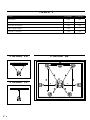 2
2
-
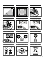 3
3
-
 4
4
-
 5
5
-
 6
6
-
 7
7
-
 8
8
-
 9
9
-
 10
10
-
 11
11
-
 12
12
-
 13
13
-
 14
14
-
 15
15
-
 16
16
-
 17
17
-
 18
18
-
 19
19
-
 20
20
-
 21
21
-
 22
22
-
 23
23
-
 24
24
-
 25
25
-
 26
26
-
 27
27
-
 28
28
-
 29
29
-
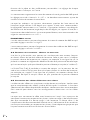 30
30
-
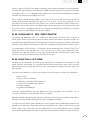 31
31
-
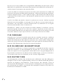 32
32
-
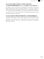 33
33
-
 34
34
-
 35
35
-
 36
36
-
 37
37
-
 38
38
-
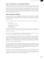 39
39
-
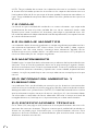 40
40
-
 41
41
-
 42
42


Dali E-50 Manual de usuario
- Categoría
- Altavoces de coche
- Tipo
- Manual de usuario
En otros idiomas
- français: Dali E-50 Manuel utilisateur
- English: Dali E-50 User manual
- Deutsch: Dali E-50 Benutzerhandbuch
- português: Dali E-50 Manual do usuário
- 日本語: Dali E-50 ユーザーマニュアル