
1
R. 05/22 855 859
SAMOA Industrial, S.A. · Pol. Ind. Porceyo, I-14 · Camino del Fontán, 831 · 33392 - Gijón - Spain · Tel.: +34 985 381 488 · www.samoaindustrial.com
2022_05_12-10:00
Part No. / Cód. / Réf. /
Art. Nr. / Деталь №:
554XXX
UP20X-XXX-XXX
Parts and technical service guide
Guía de servicio técnico y recambios
Guide d’instructions et pièces de rechange
Service- und Ersatzteilhandbuch
Список деталей и руководство по техническому обслуживанию
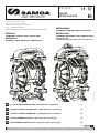
2” DOUBLE DIAPHRAGM PUMP UP20 (650 l/min-170 gal/min) 2
BOMBA DE DOBLE DIAFRAGMA 2” UP20 (650 l/min-170 gal/min) 13
POMPE À DOUBLE MEMBRANE 2” UP20 (650 l/min-170 gal/min) 24
DOPPELMEMBRANPUMPE 2” UP20 (650 l/min-170 gal/min) 33
ДВУХМЕМБРАННЫЙ НАСОС 2” UP20 (650 л/мин-170 гал/мин) 42
EN
ES
FR
DE
RU
METALLIC
ALUMINIUM, STAINLESS STEEL, DUCTILE IRON
METÁLICAS
ALUMINIO, ACERO INOXIDABLE, HIERRO DÚCTIL
METALLISCH
ALUMINIUM, ROSTFREIER STAHL, DUKTILES EISEN
MÉTALLIQUES
ALUMINIUM, ACIER INOXYDABLE, FER DUCTILE
МЕТАЛЛИЧЕСКИЙ,
АЛЮМИНИЙ, НЕРЖАВЕЮЩАЯ СТАЛЬ. КОВКИЙ ЧУГУН

2855 859 R. 05/22
SAMOA Industrial, S.A. · Pol. Ind. Porceyo, I-14 · Camino del Fontán, 831 · 33392 - Gijón - Spain · Tel.: +34 985 381 488 · www.samoaindustrial.com
2022_05_12-10:00
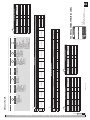
UP20
RATIO RATIO 1:1
MAXIMUM FREE FLOW MÁXIMO CAUDAL SALIDA LIBRE 650 l/min. (170 Us gal/min)
DELIVERY PER CYCLE DESPLAZAMIENTO
POR CICLO 4,5 l. (1,2 gal)
AIR PRESSURE
OPERATING RANGE RANGO DE PRESIÓN 1,5 - 8 bar (20 - 120 psi)
SOLID IN SUSPENSION
MAX SIZE
MAX. TAMAÑO DE PARTÍCULAS
EN SUSPENSIÓN 6,4 mm (1/4 in)
MAXIMUM SUCTION HEAD ALTURA MÁXIMA DE SUCCIÓN 5 m (16 ft) dry / 8 m (26,2 ft) wet
FLUID INLET/OUTLET
CONNECTIONS
ENTRADA DE
FLUIDO/CONEXIONES
DE SALIDA
2” NPT (F) Threaded / Roscada
2” BSP (F) Threaded / Roscada
2” ANSI / DIN Flange / Brida
AIR INLET ENTRADA DE AIRE 3/4” NPT (F)
AIR EXHAUST PORT SALIDA DE AIRE 1-1/2” NPT (F)
TEMPERATURE RANGE RANGO DE TEMPERATURAS
DE TRABAJO 0 - 70 ºC (32 -158 ºF)
SOUND LEVEL NIVEL SONORO 85 dB(A) @50 cycles/ciclos/min @70psi
WEIGHT PESO
48 Kg (106 lb) - Aluminium / Aluminio
78 Kg (172 lb) - Ductile Iron / Hierro dúctil
82 Kg (180 lb) - Stainless Steel / Acero inoxidable
(oz, ft, gal/min) all in EEUU units / todo en unidades EEUU.
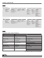
CODING / CODIFICACIÓN
UP20 X -X X X -X X X
UP20 X -X X X -X X X
CENTRAL BLOCK CONNECTIONS WETTED PARTS HARDWARE SEATS BALLS DIAPHRAGM
A Aluminium
L Conductive
polypropylene with
Stainless Steel air
chambers
B 2” BSP Threaded Ports /
Centre horizontal
C 2” ANSI/DIN Flanged Ports /
Centre Horizontal
N 2” NPTF Threaded Ports /
Centre horizontal
A Aluminium
F Ductile iron
S Stainless steel
C Carbon steel
S Stainless steel
A Aluminium
D AISI 440 Hardened
Stainless steel
H Hytrel®
M Santoprene®
N Nitrile (Buna-N)
S AISI 316
Stainless steel
T PTFE (Teon®)
H Hytrel®
M Santoprene®
N Nitrile (Buna-N)
S AISI 316
Stainless steel
T PTFE (Teon®)
V FKM (Viton®)
Conventional:
A Santoprene®
C Hytrel®
G Nitrile (Buna-N)
V FKM (Viton®)
Two-piece:
Z PTFE (Teon® with
Santoprene® backer)
Overmolded:
H Hytrel®
M Santoprene®
N Nitrile (Buna-N)
T PTFE / EPDM (Bonded)
PARTE CENTRAL CONEXIONES PARTES HUMEDAS HARDWARE ASIENTOS BOLAS DIAFRAGMAS
A Aluminio
L Polipropileno
conductivo con
cámaras de aire
de acero inoxidable
B 2” BSP Conexiones roscadas /
Centro horizontal
C 2” ANSI/DIN Conexiones con
brida / Centro horizontal
N 2” NPTF Conexiones roscadas
/ Centro horizontal
A Aluminio
F Hierro dúctil
S Acero inoxidable
C Acero
S Acero inoxidable
A Aluminio
D Acero inoxidable
endurecido AISI 440
H Hytrel®
M Santoprene®
N Nitrile (Buna-N)
S Acero inoxidable
AISI 316
T PTFE (Teon®)
H Hytrel®
M Santoprene®
N Nitrile (Buna-N)
S Acero inoxidable
AISI 316
T PTFE (Teon®)
V FKM (Viton®)
Convencional:
A Santoprene®
C Hytrel®
G Nitrile (Buna-N)
V FKM (Viton®)
Dos piezas:
Z PTFE (Teon® con
soporte de Santoprene®)
Sobremoldeados:
H Hytrel®
M Santoprene®
N Nitrile (Buna-N)
T PTFE / EPDM (Unido)
TECHNICAL DATA / DATOS TÉCNICOS
CODING: UP20X-XXX-XXX
CODIFICACIÓN: UP20X-XXX-XXX
EN
EN
ES
ES

3
R. 05/22 855 859
SAMOA Industrial, S.A. · Pol. Ind. Porceyo, I-14 · Camino del Fontán, 831 · 33392 - Gijón - Spain · Tel.: +34 985 381 488 · www.samoaindustrial.com
2022_05_12-10:00
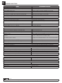
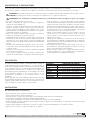
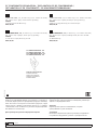
*Tested at room temperature, using
water. Flooded pump with positive
suction head.
*Ensayo realizado con agua a
temperatura ambiente y bomba
inundada de succión positiva.
AIR CONSUMPTION
CONSUMO DE AIRE
PUMP FLOW
CAUDAL
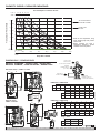
DIMENSIONS / DIMENSIONES
CAPACITY CURVE / CURVA DE CAPACIDAD
A B C D E F G H
mm 465 672 480 184 353 340 255 60
in 18 5/16” 26 29/64” 18 57/64” 7 1/4” 13 57/64” 13 25/64” 10 3/64” 2 23/64”
A B C D E F G H
mm 465 754 251 184 353 340 255 116
in 18 5/16” 29 11/16” 9 7/8” 7 1/4” 13 57/64” 13 25/64” 10 3/64” 4 9/16”
I J K L M N
mm 48 630 438 256 230 15
in 1 57/64” 24 51/64” 17 1/4” 10 5/64” 9 1/16” 19/32”
I J K L M N
mm 89 671 479 256 230 15
in 3 1/2” 26 27/64” 18 55/64” 10 5/64” 9 1/16” 19/32”
R S T
mm 165 120,6 - 125 19
in 6 1/2” 4 3/4” - 4 59/64” 3/4”
METALLIC: ALUMINIUM / STAINLESS STEEL / DUCTILE IRON
METÁLICA: ALUMINIO / ACERO INOXIDABLE / HIERRO DÚCTIL
DIMENSIONS / DIMENSIONES
DIMENSIONS / DIMENSIONES
0 100 200 300 400 500 600 700
0 26.4 52.8 79.3 105.7 132.1 158.5 184,9
l/min
US gal/min
0 11 21 42 64 85 106
0 5 10 20 30 40 50
scfm
l/sec
Fluid pressure / Presión uido
Pump ow / Caudal
Air consumption / Consumo de aire
bar psi
8
7
6
5
4
3
2
1
0
120
101.5
87
72.5
58
43.5
29
14.5
0
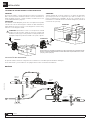
FLUID OUTLET
SALIDA FLUIDO
(2” BSP-F/NPT-F/FLANGE)
AIR INLET
ENTRADA AIRE (L)
(3/4” NPT-F)
FLUID INLET
ENTRADA FLUIDO (J)
(2” BSP-F/NPT-F/FLANGE)
AIR EXHAUST
ESCAPE DE AIRE
Threaded outlets / Salidas roscadas
Flanged outlets
Salidas con brida
Flange / Brida
BJ
K
A
I
C
G
F
H
D E
H
M
L
N
BJ
K
I
A
D E
H
C
H
G
F
T
ØS
ØR
L
M
N

2022_05_12-10:00
EN
4855 859 R. 05/22
SAMOA Industrial, S.A. · Pol. Ind. Porceyo, I-14 · Camino del Fontán, 831 · 33392 - Gijón - Spain · Tel.: +34 985 381 488 · www.samoaindustrial.com
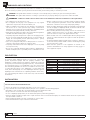
In this document you will find warnings and cautions for installation, use and maintenance of the pumps.
Here’s the meaning of symbols you may find in this document and general warnings that you should keep in mind.
WARNING: This symbol aware that there is a danger of serious bodily injury or death if you ignore the warning described.
CAUTION: This symbol aware that there is a danger of personal injury or property damage if you ignore the caution described.
• This equipment is for professional use only.
• Do not degrade the integrity of the equipment. Use only original
replacement components from Samoa Industrial, S.A.
• Fluids not suitable for the pump can cause damage to the pump unit
and involve risk of serious personal injury. Always consult Samoa
Industrial, S.A. if you have any questions about the compatibility within
the fluids and the pump materials, including elastomers.
• Install and use the pump according to all local and national regulations
and abide all health and safety laws or legislation.
• The pump can produce fluid pressures equal to the air supply pressure.
Do not exceed the maximum allowable pressure of 120 psi (8 bar) air
supply. The total hydraulic pressure (differential pressure + system)
should never exceed 120 psi (8 bar).
• Never use a pump that leaks, that is damaged, that is corroded or
otherwise it may lack the capacity to contain the fluid.
• Frequently check that the bolts on the diaphragm cover of the pump
are torqued correctly.
• Do not use a model with aluminium wetted surfaces to pump fluids for
human consumption, there is a possibility of trace contamination of lead.
• Danger of explosion if used 1,1,1-trichloroethane, methylene chloride
or other halogenated hydrocarbon solvents with aluminium wetted
materials. It could cause serious injury and property damage.
• Inside the pump, diaphragms separate the fluid that is being pumped
from the air supply. If a diaphragm breaks, the fluid can leak out of the
air exhaust and contaminate the environment.
• When handling hazardous fluids, always route the air exhaust into a
suitable container and locate it in a safe place. (Optional conection
system at customer’s request. Not supplied with the unit).
• When the fluid source level is situated higher than the pump, (flooded
suction), the outlet tank must be at a higher level than the product to
prevent spills.
• For pumps handling hazardous fluids that are a danger to humans or
to the environment, install a suitable container surrounding the pump
to prevent any leaks or spills.
• Ensure that the operators of this equipment are trained on the
operation and limitations. Use safety equipment as safety goggles or
other equipment required.
WARNING: CAREFULLY READ THE INSTRUCTIONS AND WARNINGS BEFORE OPERATING THE EQUIPMENT!
WARNINGS AND CAUTIONS
Air operated double diaphragm pumps are air-powered, reciprocating
positive displacement pumps with two pumping chambers. Two
diaphragms, centrally located in the chambers, separate the compressed
air (dry side) from the fluid being pumped (wet side). A shaft transmits
the reciprocating motion of one diaphragm to the other. A directional
valve alternatively distributes the air from one chamber to the other; thus
a reciprocating movement of the diaphragms is created. With each
stroke, fluid is discharged by one of the diaphragms whilst the opposite
diaphragm sucks new fluid into the expanding chamber. Check valves,
two on the discharge side and two on the suction side, control and direct
the fluid flow.
MATERIAL TEMPERATURE RANGE
PTFE 5 ºC - 105 ºC /41 ºF - 221 ºF
NBR 10 ºC - 80 ºC /50 ºF - 176 ºF
Acetal 10 ºC - 90 ºC /50 ºF - 194 ºF
Hytrel®10 ºC - 90 ºC /50 ºF - 194 ºF
Neopreno -18 ºC - 93 ºC /0 ºF - 200 ºF
Santoprene®-29 ºC - 135 ºC /-20 ºF - 275 ºF
Viton®-10 ºC - 177 ºC /-4 ºF - 351 ºF
Polypropylene 10 ºC - 80 ºC /50 ºF - 176 ºF
DESCRIPTION
• Remove the pump from its package and install it on the chosen location.
• Try to minimize the suction head. Install the pump as close as possible to the fluid being pumped.
• Remember to have enough space around the pump to perform maintenance tasks.
• Keep in mind to connect the inlet and outlet of the pump correctly.
• In case of diaphragm pump failure, the air exhaust will expel the product being pumped.
• When the pump is installed in a place where a spill of fluid can cause an environmental impact, the exhaust should be directed to a place.where
this spill could be contained.
• When installing the pump in its place, use brackets to secure its base.
• Fasten all bolts with the torques contained in this manual.
INSTALLATION RECOMMENDATIONS
INSTALLATION

2022_05_12-10:00
EN
5
R. 05/22 855 859
SAMOA Industrial, S.A. · Pol. Ind. Porceyo, I-14 · Camino del Fontán, 831 · 33392 - Gijón - Spain · Tel.: +34 985 381 488 · www.samoaindustrial.com
FLOODED:
The pumping system was designed with positive pressure at the inlet.
This is the best possible installation when you need to evacuate the liquid
from the drum or tank, or when working with viscous fluids.
Not recommended for hazardous fluids.
SELF-PRIMING:
Pump is designed to generate vacuum. It is possible to evacuate all the
air from a hose or pipe without damaging the pump. Maximum suction
height is (6 m) 19.69 ft, with the suction hose empty and up to 8 m
(26.25 ft) with the hose primed.
WARNING: Pump in service with a positive suction head are most
efficient when inlet pressure is limited to 0,5 bar (7 psi). Premature
diaphragm failure may occur if positive suction is 0,5 bar and higher.
NOTE: Use a pressure regulator with built-in filter inlet.
NOTE: The compressed air supply must be between 1,5 bar (20 psi ) and 8 bar (120 psi).
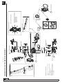
INSTALLATION
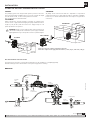
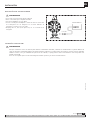
RECOMMENDED INSTALLATION
The figure below shows the recommended configuration for the installation of a diaphragm pump.
Read the warnings and recommendations of the previous page before starting.
METALLIC
SUBMERGED:
All pumps can be immersed in fluids. It is important to verify that all
components that are in contact with the fluid are chemically compatible.
In this case, air exhaust and fluid must be carried by hoses (optional air
connection).
UP PUMPS ARE VERY EASILY CONFIGURED AND EASY TO INSTALL
FLOODED
SELF-PRIMING
SUBMERGED
Discharge
valve
Support is
recommended
Shut-off
valve
MAX. 8 BAR
Regulator, filter
SUCTION
2”
Flexible
connection
AIR
Flexible
connection
Pressure
gauge
Vacuum gauge
3/4”
1/2”
2”

2022_05_12-10:00
EN
6855 859 R. 05/22
SAMOA Industrial, S.A. · Pol. Ind. Porceyo, I-14 · Camino del Fontán, 831 · 33392 - Gijón - Spain · Tel.: +34 985 381 488 · www.samoaindustrial.com
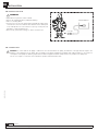
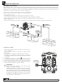
• Optional kit is required for remote exhaust.
• Remove the standard muffler in pump part drawing.
• Place 1 1/2” fitting M-M.
• Connect a hose to the new exhaust port and install the muffler at the
end of the hose. Use a hose with the same diameter as the exhaust port
1 1/2” NPT. (If the hose is more than 1.5 m (5 feet), consult your local
distributor or Samoa Industrial, S.A.).
• Have a moat, a protective housing, etc. at the end of the hose.
WARNING
INSTALLATION
AIR EXHAUST DISPOSAL
WARNING: To ensure that the air supply is sufficient to meet the demand of the pump, the diameter of the pipe must be equal to the
diameter of the supply port of the pump. Choose auxiliary air treatment equipment and fittings with sufficient airflow to exceed the air
consumption of the pump. In addition, peripheral air treatment equipment must be installed as close as possible to the pump unit.
The use of a coupler to connect the hoses aids future operation and maintenance tasks.
AIR CONNECTION
REMOTE EXHAUST
1 1/2” NPT

2022_05_12-10:00
EN
7
R. 05/22 855 859
SAMOA Industrial, S.A. · Pol. Ind. Porceyo, I-14 · Camino del Fontán, 831 · 33392 - Gijón - Spain · Tel.: +34 985 381 488 · www.samoaindustrial.com
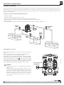
THIS PUMP IS SELF-PRIMING
To prime it the first time, you must connect the air pump supply to a low pressure using the pressure regulators while keeping the outlet valve open.
When fluid begins to flow from the pump outlet, the pump is primed. For regulation of fluid pressure, the unit must be supplied with an air pressure
between 1,5 and 8 bar (20 and 120 psi). Adjust the discharge valve on the discharge side to control flow. For the performance characteristics of the
pump see the capacity curve.
• Stop the air supply.
• Make sure for your safety that the air valve is closed.
• Close the discharge valve and the suction valve. Open inlet and outlet drain valves.
• Open the air valve of the pump, running bring on the pump and flushing the remaining fluid.
• Close the air valve.
• After ensuring that the pump was turned off and the pressure was released, pump is ready for its maintenance.
WARNING
Connect grounding wires to the pump, piping and all other
equipment too.
When the pump operates ungrounded or with an incorrect
connection, friction between parts and abrasion caused by some
fluids that flow inside the pump, can generate static electricity.
Moreover, according to the type of fluid pump and the
installation environment (such as gases in the air or the type of
the surrounding facilities) static electricity can cause fire or
electric shock.
When installing the pump, be sure to perform grounding in the specified
location.
Also connect ground wires for the auxiliary equipment and piping.
Use a grounding cable of at least 12 gauge (2.0 mm2).
If the pump you have purchased is valid for Atex, a specific Atex manual
will accompany this one. Read this manual before operating the pump.
If the unit is marked with the symbol , it can be used in potentially
explosive atmospheres. Below this symbol, in the nameplate of the pump,
are indicated the areas for which the equipment is approved. You will also
find the maximum allowable surface temperature in the same plate.
OPERATING INSTRUCTIONS
STOPPING THE PUMP FOR MAINTENANCE TASKS
GROUNDING THE PUMP
THE POSITION OF THE
GROUND WIRE
DISCHARGE
VALVE
AIR
VALVE
INLET
DRAIN VALVE
SUCTION
VALVE
OUTLET
DRAIN
VALVE

2022_05_12-10:00
EN
8855 859 R. 05/22
SAMOA Industrial, S.A. · Pol. Ind. Porceyo, I-14 · Camino del Fontán, 831 · 33392 - Gijón - Spain · Tel.: +34 985 381 488 · www.samoaindustrial.com
BALLS
DIAPHRAGM
AIR SENSOR
AIR VALVE
CENTRAL BLOCK
4
5
BALLS
3
4
3
4
12
7
8
5
6
9
10
2WETTED PARTS
2
WETTED PARTS
2WETTED PARTS
2WETTED PARTS
SOFT
SEATS
HARD SEATS
+ SEALS
3
PTFE + SANTOPRENE BACKUP
(2 PIECE DIAPHRAGM)
SINGLE PIECE
DIAPHRAGM
1_1
1_2 1_3 1_4 1_6 1_7
1_10 1_11
1_18
1_19
1_20
1_21
1_22
1_23
1_24
1_25
1_27 1_28 1_29 1_30 1_31
1_32
1_12
1_13
1_14
1_3 1_38 1_39 1_3 1_40 1_41
1_15
1_19
1_34
2_1
2_2
4
3_1
3_2
3_3
3_2
4
3_1
3_2
3_3
3_2
2_3
2_1
2_4 2_1
PUSH ROD
HARD SEATS
+ SEALS
SOFT
SEATS
5_2
5_3 5_4
5_5
1
1
1
1_18
1_35
1_5 1_8
1_16
1_36
1_9
1_17
1_26
1_20
1_33
1_37
2 PIECE DIAPHRAGM
5_3
5_1
2_4
2_5
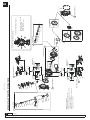
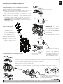
UP20 METALLIC PUMP PARTS DRAWING
NECESSARY TIGHTENING TORQUES
ATTENTION! TIGHTENING SEQUENCE
LUBRICATION / SEALANTS
- Apply mounting grease to all O-ring.
- Apply medium strength sealing to threards at
assembly (type LOCTITE 243).
- Apply anti-seize compound to threads when
using stainless steel fasteners.
- Diaphragm: 100 N·m (74 ft.lbs)
- Cover and manifolds:
80 N·M (60 ft-lbs)
- Air cap: 15 N·m (11 ft·lbs)

2022_05_12-10:00
EN
9
R. 05/22 855 859
SAMOA Industrial, S.A. · Pol. Ind. Porceyo, I-14 · Camino del Fontán, 831 · 33392 - Gijón - Spain · Tel.: +34 985 381 488 · www.samoaindustrial.com
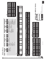
CENTRAL BLOCK
CENTRAL BODY AIR COVER AIR VALVE AIR SENSORS AIR EXHAUST AIR SHAFT SEALS KIT AIR CAP AIR PISTON
KIT CODE Qty KIT CODE Qty BSP THREAD Qty CODE Qty CODE Qty KIT CODE Qty KIT CODE Qty KIT CODE Qty KIT CODE Qty
A
UP20R-HP-5A0 1 UP20R-HP-4A0 1 UP20R-AM-1A0 1 UP20R-AM-200 1 UP20R-AM-500 1 UP20R-AM-300 1 UP20R-AM-400 1 UP20R-HP-8A0 1
(*) UP20R-HP-6A1 2
UP20R-HP-6A0 2
(*) UP20R-HP-6S1 2
SUP20R-HP-6S0 2
(*) Use with diaphragm N and T.
WETTED PARTS REPAIR KIT
FLUID COVER INLET MANIFOLD OUTLET MANIFOLD FLUID PISTON
CODE Qty BSP THREAD Qty NPT THREAD Qty FLANGED Qty BSP THREAD Qty NPT THREAD Qty FLANGED Qty CODE Qty
AUP20R-HP-3A0 1 UP20R-HP-1AB 1 UP20R-HP-1AN 1 UP20R-HP-1AC 1 UP20R-HP-2AB 1 UP20R-HP-2AN 1 UP20R-HP-2AC 1 UP20R-HP-7A0 1
FUP20R-HP-3F0 1 UP20R-HP-1FB 1 UP20R-HP-1FN 1 UP20R-HP-1FC 1 UP20R-HP-2FB 1 UP20R-HP-2FN 1 UP20R-HP-2FC 1 N/A -
SUP20R-HP-3S0 1 UP20R-HP-1SB 1 UP20R-HP-1SN 1 UP20R-HP-1SC 1 UP20R-HP-2SB 1 UP20R-HP-2SN 1 UP20R-HP-2SC 1 UP20R-HP-7S0 1
SEALS & SEATS REPAIR KIT
SEATS SEALS KIT CODE Qty NUMERICAL CODING
55XXXX
A T UP20R-WP-A00 4 -
D T UP20R-WP-D00 4 -
H(No seals) UP20R-WP-H00 4 554510
M(No seals) UP20R-WP-M00 4 -
N(No seals) UP20R-WP-N00 4 554530
S T UP20R-WP-S05 4 -
T T UP20R-WP-T00-1 4 -
- T UP20R-WP-999 8 -
TECHNICAL CHARACTERISTICS LABEL
MODEL:
55XXXX (numerical coding)
UP20X-XXX-XXX (alphanumeric coding)
METALLIC PUMP
1
2
3
II 2G Ex h IIB/IIC T6...T5 Gb
II 2D Ex h IIIB T70ºC...T95ºC Db
LOM 20.115M-CX
0163
CODE:
MAXIMUM AIR PRESSURE:
MAXIMUM FLUID PRESSURE:
FLUID IN / OUT:
MFG. DATE: SERIAL No.:
MODEL:
www.samoaindustrial.com
MADE IN SPAIN • PATENTED
BALL VALVE REPAIR KIT
BALLS KIT CODE Qty NUMERICAL CODING
55XXXX
HUP20R-WP-0H0 4 554510
MUP20R-WP-0M0 4 -
NUP20R-WP-0N0 4 554530
SUP20R-WP-0S0 4 -
TUP20R-WP-0T0 4 -
VUP20R-WP-0V0 4 -
4
DIAPHRAGMS REPAIR KIT
DIAPHRAGM KIT CODE Qty NUMERICAL CODING
55XXXX
AUP20R-WP-00A 2 -
CUP20R-WP-00C 2 554510
GUP20R-WP-00G 2 554530
VUP20R-WP-00V 2 -
ZUP20R-WP-00Z-1 2 -
NUP20R-WP-00N 2 -
HUP20R-WP-00H 2 -
MUP20R-WP-00M 2 -
TUP20R-WP-00T 2 -
5
UP20 X -X X X -X X X
CENTRAL BLOCK CONNECTIONS WETTED PARTS BOLTS SEATS BALLS DIAPHRAGM
A Aluminium
L Conductive
polypropylene with
Stainless Steel air
chambers
B 2” BSP
Threaded Ports /
Centre horizontal
C 2” ANSI/DIN
Flanged Ports /
Centre Horizontal
N 2” NPTF
Threaded Ports /
Centre horizontal
A Aluminium
F Ductile iron
S Stainless steel
C Carbon steel
S Stainless steel
A Aluminium
D AISI 440 Hardened
Stainless steel
H Hytrel®
M Santoprene®
N Nitrile (Buna-N)
S AISI 316
Stainless steel
T PTFE (Teon®)
H Hytrel®
M Santoprene®
N Nitrile (Buna-N)
S AISI 316
Stainless steel
T PTFE (Teon®)
V FKM (Viton®)
Conventional:
A Santoprene®
C Hytrel®
G Nitrile (Buna-N)
V FKM (Viton®)
Two-piece:
Z PTFE (Teon® with
Santoprene® backer)
Overmolded:
H Hytrel®
M Santoprene® (one-piece)
N Nitrile (Buna-N)
T PTFE / EPDM (Bonded)
1 2 3 4 5

2022_05_12-10:00
EN
10 855 859 R. 05/22
SAMOA Industrial, S.A. · Pol. Ind. Porceyo, I-14 · Camino del Fontán, 831 · 33392 - Gijón - Spain · Tel.: +34 985 381 488 · www.samoaindustrial.com
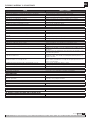
TROUBLESHOOTING
CAUSE RECOMMENDED MEASURE
THE PUMP DOES NOT WORK
The discharge valve on the discharge side is not open. Open the discharge valve on the discharge side.
No air supply. Turn on the compressor and open the air valve and air regulator.
The air supply pressure is low. Check the compressor and the configuration of the air line.
Air leaks in connecting elements. Check the connection elements and the tightening of the screws.
The air pipes or ancillary equipment is clogged with mud. Check and clean the air line.
The exhaust port (muffler) of the pump is clogged with mud. Check and clean the exhaust port and muffler.
The fluid pipe is clogged with mud. Check and clean the fluid line.
Pump is clogged with mud. Remove, inspect and clean the pump.
THE PUMP RUNS BUT NO FLUID COMES OUT
The valve on the suction side is not open. Open the valve on the suction side.
Too much suction or discharge height. Confirm the configuration of the pipe and reduce the height of the
same.
Fluid pipe discharge side (including the filter) is clogged with mud. Check and clean the fluid line.
Pump is clogged with mud. Dismantle the pump, check and clean.
The ball and ball seat is worn or damaged. Inspect and replace parts.
THE FLOW IS DECREASING
The air supply pressure is low. Check the compressor and the configuration of the air line.
The air line or peripheral equipment clogged with mud. Check and clean the air line.
Valve discharge side drive will not open normally. Adjust the discharge valve discharge side.
The air mixes with the fluid. Replenish fluid and check the configuration of the pipe on the suction side.
Cavitation occurs. Adjust air supply pressure and discharge pressure and reduce the suction.
Vibrations. Adjust air supply pressure and discharge pressure. Reduce the flow of the
inlet valve to adjust pressure and volume of fluid.
Ice formation in the air exhaust. Remove ice from the air bypass valve and check and clean the air filter.
Use a pipe in the exhaust air that the ice does not form in the muffler.
The fluid line (including the filter) plugged with mud. Check and clean the fluid pipe and strainer.
The exhaust port (muffler) of the pump is clogged with mud. Check and clean the exhaust port and muffler.
Pump is clogged with mud. Remove, inspect and clean the pump body.
LEAKAGE OF FLUID THROUGH THE HOLLOW EXHAUST (SILENCER)
The diaphragm is damaged. Remove and inspect the pump and replace the diaphragm.
IRREGULAR NOISE
The air supply pressure is too high. Adjust air supply pressure.
The pump is clogged with sludge particles larger than the diameter allowed. Remove, check and clean the pump.
IRREGULAR VIBRATION
The elements of connection and the support of the pump are loose. Review each element of connection and tighten the screws.
The air supply pressure is too high. Adjust air supply pressure.
The range and ball valve vibrates. Adjust air supply pressure and exhaust pressure.
POWERED AIR LEAK PRESSURE OF 1,5 TO 8 BAR (20 TO 120 PSI)
Wear air valve. Replace air valve.
NO START-UP AND IS LEAKING AIR WITHOUT CYCLES
Stiff air sensors. Change air sensor.
Wear air valve. Replace.
IN FLUID WITH AIR BUBBLES
Diaphragm damaged. Replace diaphragm.
Suction hose loose or broken. Tighten or replace.

2022_05_12-10:00
EN
11
R. 05/22 855 859
SAMOA Industrial, S.A. · Pol. Ind. Porceyo, I-14 · Camino del Fontán, 831 · 33392 - Gijón - Spain · Tel.: +34 985 381 488 · www.samoaindustrial.com
REPAIR AND MAINTENANCE PROCEDURES
For proper operation of the pump and to prevent accidents which may
damage equipment and in the worst case, people, you must periodically
review the torques of the diaphragms covers and the DIRECTIONAL
VALVE. In the next table are shown the appropriate torques for this
purpose:
TORQUES
UP20
Cover and manifolds 80 N·m (60 ft.lbs)
Air cap 15 N·m (11 ft.lbs)
Diaphragms 100 N·m (74 ft.lbs)
TORQUES NECESSARY FOR THE PROPER FUNCTIONING OF THE PUMP
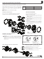
DIAPHRAGM MAINTENANCE
Before any intervention: DISCONNECT AIR SUPPLY OF THE PUMP.
CAUTION: Follow next procedure to ensure the diaphragms are
correctly installed. If not followed diaphragm bead could be
extruded out of its housing with the resulting damage over the
diaphragm bead and thus possible fluid leaks or premature
diaphragm failure.
1. Correct assembly of the
diaphragm before the
diaphragm cover assembly.
2. Incorrect assembly of the
diaphragm.
Possible damage when
assembling the diaphragm cover.
CAUTION!
CAUTION!: DO NOT OVERTIGHTEN FASTENERS.
ANTICIPATE A POSSITE LEAKAGE OF FLUID INSIDE THE PUMP.
REPLACING THE DIAPHRAGM:
1. Close inlet and discharge fluid valves.
2. Drain the fluid inside the pump.
3. Remove the discharge manifold screws and lift the
discharge manifold. Remove the valve seats, o-ring (if
applicable) and balls.
4. Invert the pump for remove de inlet manifold screws and
lift the inlet manifold. Remove the valve seats, o-ring (if
applicable) and balls.
5. Remove the fluid cover screws and remove it by gently
pulling back.
6. Remove the used diaphragm. For one-piece diaphragms
unscrew by pulling with the hand, in case of a diaphragm
with outer piston (two pieces) use an adjustable wrench.
7. Repeat for opposite side.
NOTE:
To tighten the screws you must use a torque wrench
calibrated (see table in this page).
Follow the procedure for “replacing the diaphragm”
1. Remove air cover screws.
2. Lift away the air cover from the central body.
3. Now the bushing and seals can be replaced. Clean the
area and apply lubricate.
4. Fit the remaining components in reverse order.
INSTALLING THE NEW DIAPHRAGMS -
ASSEMBLING PROCEDURE
SHAFT, BUSHINGS AND SEALS MAINTENANCE
This side
to air
chamber
Diaphragm (two pieces)

2022_05_12-10:00
EN
12 855 859 R. 05/22
SAMOA Industrial, S.A. · Pol. Ind. Porceyo, I-14 · Camino del Fontán, 831 · 33392 - Gijón - Spain · Tel.: +34 985 381 488 · www.samoaindustrial.com
REPAIR AND MAINTENANCE PROCEDURES
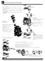
AIR SENSOR MAINTENANCE
AIR VALVE
MAINTENANCE
The air sensors are on the central body.
To access them, follow the procedure for “Replacing diaphragms”.
Once removed the covers following procedure:
1. Remove the two screws that secure the air sensor to the top.
2. Remove all components of the sensor. Clean the area.
3. Introduce new components in the order shown.
4. Fit the remaining components in reverse order. Fit the sensor cover and tighten the screws.
1. Remove the six screw of the “aircap”.
2. Remove the “aircap” and pull out
the air valve.
3. Place the bottom gasket in the
new air valve.
4. Insert the new air valve.
5. Place the “aircap” with the gaskets
in its housing.
6. Tighten the screws with a maximum
torque of 15 N·m (11 ft.lbs).
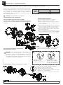
BALL VALVES AND SEATS MAINTENANCE
1. Close fluid valves.
2. Drain the fluid from inside the pump. Anticipate a drainage of fluid
from inside the pump.
3. Remove the inlet and outlet manifolds. Take note of the orientation of
the manifolds.
4. Install a new set of valves or seats according to these assembly
drawings. Tighten the manifold bolts with a maximum torque of
80 N·m (60 ft.lbs).
IMPORTANT: Always approximate manifold bolts before final
tightening.
IMPORTANT:
Follow the diaphragm maintenance procedure to ensure
no damage in the diaphragm during its assembly.
IMPORTANT:
Soft seats (NBR, Hytrel® and
Santoprene®) don’t need extra
seals and the seat is simetric.
Hard seats (PP, POM, PVDF,
aluminum, stainless steel), use
additional o-rings for sealing.
Balls must be always assembled
over the seat.
IMPORTANT: When doing a
pump maintenance that implies
manifold disassembling and pump
is fitted with PTFE o-rings (white
colour), they must be replaced by
new ones in order to avoid fluid
leakages”.
Soft Seat
Hard seat
assembly
Outlet manifold bolts
80 N·m (60 ft.lbs)
Inlet manifold bolts
80 N·m (60 ft.lbs)

2022_05_12-10:00
EN
13
R. 05/22 855 859
SAMOA Industrial, S.A. · Pol. Ind. Porceyo, I-14 · Camino del Fontán, 831 · 33392 - Gijón - Spain · Tel.: +34 985 381 488 · www.samoaindustrial.com
ES
En este documento usted encontrará advertencias y precauciones para la instalación, uso y mantenimiento de las bombas.
A continuación le indicamos el significado de los símbolos y mencionamos unas advertencias generales que usted debe tener en cuenta.
ADVERTENCIA: Este símbolo alerta de que si no se siguen las instrucciones indicadas se puede producir una situación de lesión grave o muerte.
ATENCIÓN: Este símbolo alerta de daños o destrucción del equipamiento si no se siguen las instrucciones.
ADVERTENCIAS Y PRECAUCIONES
• Este equipo es únicamente para uso profesional.
• No altere la integridad del equipo. Use solamente componentes
originales de Samoa Industrial, S.A.
• Los fluidos no adecuados para la bomba pueden causar daños a la
unidad de la bomba e implicar riesgo de graves daños personales.
Consulte siempre al distribuidor de Samoa Industrial, S.A. si se tiene
alguna duda sobre la compatibilidad de los fluidos con los materiales
de la bomba, incluyendo los elastómeros.
• Instale y use siempre la bomba según la normativa y la legislación
sanitaria y de seguridad, tanto local como nacional.
• La bomba puede producir presiones de fluido iguales a la presión de
alimentación del aire. No exceder la presión máxima permitida de
alimentación de aire de 8 bar (120 psi). La presión hidráulica total
(presión del sistema + presión diferencial) no deberá exceder nunca 8 bar
(120 psi).
• No utilice nunca una bomba que tenga fugas o daños, esté corroída o
de otra forma carezca de la capacidad para contener el fluido interno
o la presión del aire.
• Comprobar con frecuencia que los tornillos de las tapas de la bomba
están correctamente apretados.
• No use modelos cuya parte húmeda esté basada en aluminio para
productos de consumo humano, es posible que existan trazas de plomo.
• Peligro de explosión si se usa 1,1,1-tricloroetano, cloruro de metileno
u otros disolventes de hidrocarburos halogenados en sistemas de fluido
a presión que tengan componentes de aluminio en la parte de fluido.
Podría causar graves daños materiales y personales incluso mortales.
• En el interior de la bomba, dos membranas separan el fluido bombeado
de la alimentación de aire. Si se rompe una membrana, el fluido puede
salir proyectado por el orificio de evacuación de aire.
• Cuando se manejen fluidos peligrosos, conecte siempre el orificio de
evacuación de aire a un recipiente adecuado y situado en un lugar
seguro. (Sistema de conexión opcional a petición del cliente. No se
suministra con el equipo).
• Cuando la fuente de producto se encuentre a un nivel más elevado que
la bomba (aspiración inundada), la impulsión deberá ser dirigida por
un tubo a un nivel más alto que el producto para impedir los derrames
causados por derivación sifónica.
• En las bombas que manejen fluidos peligrosos para las personas o el
medio ambiente, se debe instalar algún tipo de recipiente o contenedor
para recoger posibles fugas y evitar su derrame.
• Asegúrese de que el operario de este equipo esté formado en cuanto a
la operación, limitaciones y uso de equipamiento de seguridad como
gafas de seguridad u otro equipamiento requerido.
ADVERTENCIA: ¡Lea atentamente el manual de instrucciones y sus advertencias antes de empezar a operar con el equipo!
La bomba de membrana neumática es una bomba aspirante e impelente
de desplazamiento positivo, accionada por aire y con dos cámaras de
bombeo. Dos membranas ubicadas centralmente en las cámaras, separan
el aire comprimido (lado seco) del fluido bombeado (lado húmedo). Las
membranas están conectadas entre sí mediante un eje flotante cuyo
funcionamiento permite la minimización del flujo pulsante. Una válvula
(motor neumático) distribuye el aire de una cámara a la otra
alternativamente, produciendo así un movimiento recíproco de las
membranas.
En cada embolada, una de las membranas desplaza el fluido, mientras
que la membrana opuesta aspira nuevo fluido al interior de la cámara de
expansión. Cuatro válvulas de bola, dos en el lado de aspiración y dos en
el lado de impulsión, controlan y dirigen el flujo del fluido.
MATERIALES TEMPERATURA DE TRABAJO
PTFE 5 ºC - 105 ºC /41 ºF - 221 ºF
NBR 10 ºC - 80 ºC /50 ºF - 176 ºF
Acetal 10 ºC - 90 ºC /50 ºF - 194 ºF
Hytrel®10 ºC - 90 ºC /50 ºF - 194 ºF
Neopreno -18 ºC - 93 ºC /0 ºF - 200 ºF
Santoprene®-29 ºC - 135 ºC /-20 ºF - 275 ºF
Viton®-10 ºC - 177 ºC /-4 ºF - 351 ºF
Polipropileno 10 ºC - 80 ºC /50 ºF - 176 ºF
DESCRIPCIÓN
INSTALACIÓN
• Retire la bomba de la caja e instálela en el lugar elegido.
• Trate de reducir al mínimo la altura de aspiración.
• Recuerde disponer de espacio suficiente alrededor de la bomba para realizar las tareas de mantenimiento.
• Tenga siempre en cuenta usar correctamente la entrada y la salida de la bomba.
• En caso de fallo del diafragma el escape de aire de la bomba puede contener el producto bombeado.
• Cuando la bomba se instala en un lugar en el que pueda tener lugar un impacto en el medio ambiente, el escape debe orientarse hacia un lugar
donde no haya impacto ambiental.
• Cuando instale la bomba en su lugar, utilice los soportes en la base y asegure la bomba fijándola con los tornillos de amarre.
• Apriete todos los tornillos con el par recomendado en este manual.
RECOMENDACIONES INSTALACIÓN

2022_05_12-10:00
EN
14 855 859 R. 05/22
SAMOA Industrial, S.A. · Pol. Ind. Porceyo, I-14 · Camino del Fontán, 831 · 33392 - Gijón - Spain · Tel.: +34 985 381 488 · www.samoaindustrial.com
ES
INUNDADA
El sistema de bombeo se diseñó para presión positiva en la aspiración.
Esta es la mejor forma de instalación cuando se necesite evacuar todo el
líquido del bidón o depósito, o cuando se trabaje con fluidos viscosos. No
recomendada para fluidos peligrosos.
ASPIRACIÓN:
La bomba UP está diseñada para generar vacío en la aspiración. Es posible
evacuar todo el aire de una manguera o tubería sin dañar la bomba. La
altura máxima de succión es de 6 m con la manguera de succión vacía y
hasta 8 m con la manguera cebada.
ATENCIÓN: Las bombas en servicio con una presión de entrada
positiva son más eficientes cuando la presión de entrada está
limitada a 0,5 bar (7 psi). Puede producirse un fallo prematuro del
diafragma si la presión positiva de entrada es de 0,5 bar o superior.
NOTA: Utilice un regulador de presión con filtro incorporado en la entrada de aire.
NOTA: La presión de alimentación de aire debe estar comprendida entre 1,5 bar
(20 psi) y 8 bar (120 psi).
SUMERGIDO:
Todas las bombas UP se pueden sumergir en los fluidos. Es importante
que verifique que todos los componentes que están en contacto con el
fluido son químicamente compatibles. En este caso, las salidas de aire y
fluido deben ser conducidas al exterior mediante mangueras. (Sistema de
conexión de aire opcional).
LAS BOMBAS UP SON MUY FLEXIBLES Y FÁCILES DE INSTALAR
INSTALACIÓN RECOMENDADA
El esquema de abajo muestra la configuración de la instalación recomendada para una bomba de diafragma.
Lea las advertencias y recomendaciones de la página anterior antes de realizar dicha instalación
METÁLICA
INUNDADA
ASPIRACIÓN
SUMERGIDA
INSTALACIÓN
Válvula de
impulsión
Se recomienda
soporte
Llave de
paso
MAX. 8 BAR
Regulador, filtro
SUCCIÓN
2”
Conexión
flexible
AIRE
Conexión
flexible
Manómetro
Vacuometro
3/4”
1/2”
2”

2022_05_12-10:00
EN
15
R. 05/22 855 859
SAMOA Industrial, S.A. · Pol. Ind. Porceyo, I-14 · Camino del Fontán, 831 · 33392 - Gijón - Spain · Tel.: +34 985 381 488 · www.samoaindustrial.com
ES
ADVERTENCIA
Para que el suministro de aire sea suficiente para satisfacer la demanda de la bomba, el diámetro de la tubería debe ser igual al diámetro del
orificio de suministro de la bomba. También elija equipos auxiliares y materiales con suficiente flujo de aire para el consumo de aire de la bomba.
También considere el uso y la estabilidad de la presión de aire. Además, el equipo periférico debe estar instalado lo más cerca posible de la
unidad de la bomba.
El uso de un acoplador para conectar cada manguera facilita la operación y las tareas de mantenimiento.
• Es necesario el kit opcional de salida conducida.
• Retire el silenciador que acompaña la bomba.
• Coloque el adaptador de 1 1/2” M-M.
• Conecte esa manguera al adaptador e instale un silencioso al otro lado
de la manguera. Use esa manguera con el mismo diámetro de
manguera y conexiones de 1 1/2” NPT.
• Disponga un foso, una caja de protección, etc. en el extremo de la
manguera.
ADVERTENCIA
INSTALACIÓN
DISPOSICIÓN DEL ESCAPE EXTERIOR
CONEXIÓN TOMA DE AIRE
REMOTE EXHAUST
1 1/2” NPT

2022_05_12-10:00
EN
16 855 859 R. 05/22
SAMOA Industrial, S.A. · Pol. Ind. Porceyo, I-14 · Camino del Fontán, 831 · 33392 - Gijón - Spain · Tel.: +34 985 381 488 · www.samoaindustrial.com
ES
ESTA BOMBA ES AUTO-CEBANTE.
Para cebarla la primera vez, es conveniente conectar el aire a la bomba a baja presión con el regulador de presión, manteniendo la válvula de salida abierta.
Cuando el fluido empieza a salir, la bomba está cebada. Para su regulación mediante presión de fluido se debe alimentar con presión de aire
comprendida entre 1,5 y 8 bar (20 - 120 psi). Ajuste la válvula de impulsión en el lado de descarga. Para la relación entre el flujo, la presión de
suministro de aire y la presión de descarga, vea la curva de capacidad.
• Corte el suministro de aire.
• Compruebe por su seguridad que la válvula de aire de la bomba esté cerrada.
• Cierre las válvulas de aspiración y descarga. Abra las válvulas de drenaje (aspiración e impulsión).
• Abra la válvula de aire de la bomba, ponga en funcionamiento la bomba y descargue el fluido remanente.
• Cierre la válvula de aire.
• Asegúrese de que la bomba se ha detenido y no existe presión en las líneas de fluido. La bomba está lista para el mantenimiento.
ADVERTENCIA:
Asegúrese de conectar conductores a tierra para la bomba,
tuberías y otros equipos conectados.
Cuando la bomba opera sin conexión a tierra o con una conexión
incorrecta, la fricción entre las piezas y la abrasión causada por
algunos fluidos que fluyen dentro de la bomba pueden generar
electricidad estática. Además, según el tipo de fluido a bombear
y el ambiente de la instalación (como gases en el aire o el tipo de
las instalaciones circundantes) la electricidad estática puede ser
causa de incendio o choque eléctrico.
• Cuando instale la bomba, asegúrese de realizar la conexión a tierra en
el lugar especificado.
• Conecte también conductores a tierra para los equipos auxiliares
y las tuberías.
• Utilice un cable con conexión a tierra de por lo menos 2,0 mm2.
• Si la bomba que ha adquirido es válida para Atex, a este manual lo
acompañará uno específico para Atex. Lea este manual antes de operar
con la bomba.
• Si la bomba viene marcada con el símbolo , esta puede ser usada
en atmósferas potencialmente explosivas. Debajo de este símbolo, en
las placa de identificación de la bomba, vienen indicadas las zonas para
las que el equipo está aprobado. Encontrará también la temperatura de
superficie máxima permitida en la placa de su bomba.
MODO DE OPERACIÓN
PARADA DE LA BOMBA PARA TAREAS DE MANTENIMIENTO
CONEXIÓN A TIERRA
POSICIÓN DEL
CABLE A TIERRA
VÁLVULA
DE DESCARGA
VÁLVULA
DE AIRE
VÁLVULA
DE DESCARGA
VÁLVULA
DE DRENAJE
ASPIRACIÓN
VÁLVULA
DE DRENAJE
IMPULSIÓN

2022_05_12-10:00
EN
17
R. 05/22 855 859
SAMOA Industrial, S.A. · Pol. Ind. Porceyo, I-14 · Camino del Fontán, 831 · 33392 - Gijón - Spain · Tel.: +34 985 381 488 · www.samoaindustrial.com
ES
POSIBLES AVERÍAS Y SOLUCIONES
CAUSA MEDIDA A TOMAR
LA BOMBA NO FUNCIONA
La válvula de impulsión en el lado de descarga no está abierta. Abra la válvula de impulsión en el lado de descarga.
No llega aire. Encienda el compresor y abra la válvula de aire y el regulador de aire.
La presión de suministro de aire es baja. Revise el compresor y la configuración de la tubería de aire.
Fugas de aire en elementos de conexión. Revise los elementos de conexión y el apriete de los tornillos.
La tubería de aire o el equipo auxiliar está obstruido con lodo. Revise y limpie la tubería de aire.
El orificio de escape (silenciador) de la bomba está obstruido con lodo. Revise y limpie el orificio de escape y el silenciador.
La tubería de fluido está obstruida con lodo. Revise y limpie la tubería de fluido.
La bomba está obstruida con lodo. Desmonte, revise y limpie la bomba.
LA BOMBA FUNCIONA PERO EL FLUIDO NO SALE
La válvula en el lado de succión no está abierta. Abra la válvula en el lado de succión.
Demasiada altura de aspiración o altura de descarga. Confirme la configuración de la tubería y reduzca la altura de la misma.
La tubería de fluido del lado de descarga (incluido el filtro) está obstruida
con lodo.
Revise y limpie la tubería de fluido.
La bomba está obstruida con lodo. Desmonte la bomba, revísela y límpiela.
Las bolas y el asiento de la bola están desgastados o dañados. Revise y reemplace piezas defectuosas.
EL FLUJO ESTÁ DISMINUYENDO
La presión de suministro de aire es baja. Revise el compresor y la configuración de la tubería de aire.
La tubería de aire o el equipo periférico está obstruido con lodo. Revise y limpie la tubería de aire.
La válvula de impulsión del lado de descarga no se abre normalmente. Ajuste la válvula de impulsión del lado de descarga.
El aire se mezcla con el fluido. Vuelva a llenar de fluido y revise la configuración de la tubería del lado
de succión.
Se produce cavitación. Ajuste la presión de suministro de aire y la presión de descarga y reduz-
ca la altura de aspiración.
Se producen vibraciones.
Ajuste la presión de suministro de aire y la presión de descarga.
Disminuya el flujo de la válvula de entrada para ajustar la presión y el
volumen de fluido.
Formación de hielo en el escape de aire.
Elimine el hielo de la válvula de desvío de aire y revise y limpie el filtro
de aire. Utilice una tubería en el escape de aire para que el hielo no se
forme en el silenciador.
La tubería de fluido (incluido el filtro) está obstruida con lodo. Revise y limpie la tubería de fluido y el filtro.
El orificio de escape (silenciador) de la bomba está obstruido con lodo. Revise y limpie el orificio de escape y el silenciador.
La bomba está obstruida con lodo. Desmonte, revise y limpie la bomba.
FUGAS DE FLUIDO POR EL ORIFICO DE ESCAPE (SILENCIADOR)
El diafragma está dañado. Desmonte y revise la bomba y reemplace el diafragma.
RUIDO IRREGULAR
La presión de suministro de aire es demasiado alta. Ajuste la presión de suministro de aire.
La bomba está obstruida con lodo de partículas más grandes que el
diámetro permitido. Desmonte, revise y limpie la bomba.
FUGA AIRE ALIMENTADO A PRESIÓN ENTRE 1,5 y 8 bar (20 y 120 psi)
Desgaste del pivote de la válvula de aire. Cambie la válvula de aire.
NO ARRANCA Y QUEDA FUGANDO AIRE SIN HACER CICLOS
Sensores de aire agarrotados. Cambie sensor de aire.
Tambor de salida del pivote desgastado. Cambie la válvula de aire.
EL FLUIDO SALE CON BURBUJAS DE AIRE
Membrana dañada. Sustituya la membrana.
Manguera de succión suelta o rota. Apriete o sustituya.

2022_05_12-10:00
EN
18 855 859 R. 05/22
SAMOA Industrial, S.A. · Pol. Ind. Porceyo, I-14 · Camino del Fontán, 831 · 33392 - Gijón - Spain · Tel.: +34 985 381 488 · www.samoaindustrial.com
ES
BOMBA METÁLICA UP20, DIBUJO DE RECAMBIOS
BOLAS
DIAFRAGMA
SENSOR DE AIRE
DISTRIBUIDOR DE AIRE
CUERPO BOMBA
4
5
BOLAS
3
4
3
4
12
7
8
5
6
9
10
2PARTES HÚMEDAS
2
PARTES HÚMEDAS
2PARTES HÚMEDAS
2PARTES HÚMEDAS
ASIENTOS
BLANDOS
ASIENTOS DUROS
+ JUNTAS
3
DIAFRAGMA
1 PIEZA
1_1
1_2 1_3 1_4 1_6 1_7
1_10 1_11
1_18
1_19
1_20
1_21
1_22
1_23
1_24
1_25
1_27 1_28 1_29 1_30 1_31
1_32
1_12
1_13
1_14
1_3 1_38 1_39 1_3 1_40 1_41
1_15
1_19
1_34
2_1
2_2
4
3_1
3_2
3_3
3_2
4
3_1
3_2
3_3
3_2
2_3
2_1
2_4 2_1
BARRA EMPUJE
ASIENTOS DUROS
+ JUNTAS
ASIENTOS
BLANDOS
5_2
5_3 5_4
5_5
1
1
1
1_18
1_35
1_5 1_8
1_16
1_36
1_9
1_17
1_26
1_20
1_33
1_37
DIAFRAGMA 2 PIEZAS
5_3
5_1
2_4
2_5
MEMBRANA TIPO SANDWICH
PTFE (DIAFRAGMA 2 PIEZAS)
PARES DE APRIETE NECESARIOS
¡ATENCIÓN! SECUENCIA DE APRIETE
LUBRICACIÓN / SELLADORES
- Aplicar grasa de montaje a todas las
juntas.
- Aplicar fijador de resistencia media
para el sellado de roscas
(tipo LOCTITE 243).
- Aplicar compuesto antiagarrotante a
las roscas cuando se usen tornillos de
acero inoxidable.
- Diafragmas: 100 N·m (74 ft.lbs)
- Tapa de diafragma y colectores:
80 N·M (60 ft-lbs)
- Tapa válvula de aire:
15 N·m (11 ft·lbs)

2022_05_12-10:00
EN
19
R. 05/22 855 859
SAMOA Industrial, S.A. · Pol. Ind. Porceyo, I-14 · Camino del Fontán, 831 · 33392 - Gijón - Spain · Tel.: +34 985 381 488 · www.samoaindustrial.com
ES
KIT REPARACIÓN PARTES HÚMEDAS
TAPA FLUIDO COLECTORES ENTRADA COLECTORES SALIDA PISTÓN DE FLUIDO
CÓD. Cant. ROSCA BSP Cant. ROSCA BSP Cant. ROSCA NPT Cant. ROSCA BSP Cant. ROSCA NPT Cant. CON BRIDA Cant. CÓD. Cant.
AUP20R-HP-3A0 1 UP20R-HP-1AB 1 UP20R-HP-1AN 1 UP20R-HP-1AC 1 UP20R-HP-2AB 1 UP20R-HP-2AN 1 UP20R-HP-2AC 1 UP20R-HP-7A0 1
FUP20R-HP-3F0 - UP20R-HP-1FB 1 UP20R-HP-1FN 1 UP20R-HP-1FC 1 UP20R-HP-2FB 1 UP20R-HP-2FN 1 UP20R-HP-2FC 1 N/A -
SUP20R-HP-3S0 - UP20R-HP-1SB 1 UP20R-HP-1SN 1 UP20R-HP-1SC 1 UP20R-HP-2SB 1 UP20R-HP-2SN 1 UP20R-HP-2SC 1 UP20R-HP-7S0 1
KIT REPARACIÓN JUNTAS Y ASIENTOS
ASIENTOS JUNTAS CÓD. KIT Cant. CODIFICACIÓN
NUMÉRICA 55XXXX
A T UP20R-WP-A00 4 -
D T UP20R-WP-D00 4 -
H(Sin juntas) UP20R-WP-H00 4 554510
M(Sin juntas) UP20R-WP-M00 4 -
N(Sin juntas) UP20R-WP-N00 4 554530
S T UP20R-WP-S05 4 -
T T UP20R-WP-T00-1 4 -
- T UP20R-WP-999 8 -
BLOQUE CENTRAL
DISTRIBUIDOR AIRE TAPA DE AIRE VÁLVULA DE AIRE SENSORES DE AIRE ESCAPES DE AIRE EJE DE AIRE KIT JUNTAS TAPA AIRE PISTÓN AIRE
CÓD. KIT Cant. CÓD. KIT Cant. ROSCA BSP Cant. CÓD. Cant. CÓD. Cant. CÓD. KIT Cant. CÓD. KIT Cant. CÓD. KIT Cant. CÓD. KIT Cant.
A
UP20R-HP-5A0 1 UP20R-HP-4A0 1 UP20R-AM-1A0 1 UP20R-AM-200 1 UP20R-AM-500 1 UP20R-AM-300 1 UP20R-AM-400 1 UP20R-HP-8A0 1
(*) UP20R-HP-6A1 2
UP20R-HP-6A0 2
(*) UP20R-HP-6S1 2
SUP20R-HP-6S0 2
ETIQUETA CARACTERÍSTICAS TÉCNICAS
MODELO:
55XXXX (codificación numérica)
UP20X-XXX-XXX (codificación alfanumérica)
(*) Usar con diafragmas N y T.
BOMBA METÁLICA
1
2
3
II 2G Ex h IIB/IIC T6...T5 Gb
II 2D Ex h IIIB T70ºC...T95ºC Db
LOM 20.115M-CX
0163
CODE:
MAXIMUM AIR PRESSURE:
MAXIMUM FLUID PRESSURE:
FLUID IN / OUT:
MFG. DATE: SERIAL No.:
MODEL:
www.samoaindustrial.com
MADE IN SPAIN • PATENTED
KIT REPARACIÓN BOLA DE VÁLVULA
BOLAS CÓD. KIT Cant. CODIFICACIÓN
NUMÉRICA 55XXXX
HUP20R-WP-0H0 4 554510
MUP20R-WP-0M0 4 -
NUP20R-WP-0N0 4 554530
SUP20R-WP-0S0 4 -
TUP20R-WP-0T0 4 -
VUP20R-WP-0V0 4 -
4
KIT REPARACIÓN DIAFRAGMA
DIAFRAGMA CÓD. KIT Cant. CODIFICACIÓN
NUMÉRICA 55XXXX
AUP20R-WP-00A 2 -
CUP20R-WP-00C 2 554510
GUP20R-WP-00G 2 554530
VUP20R-WP-00V 2 -
ZUP20R-WP-00Z-1 2 -
NUP20R-WP-00N 2 -
HUP20R-WP-00H 2 -
MUP20R-WP-00M 2 -
TUP20R-WP-00T 2 -
5
UP20 X -X X X -X X X
PARTE CENTRAL CONEXIONES PARTES
HÚMEDAS TORNILLOS ASIENTOS BOLAS DIAFRAGMAS
A Aluminio
L Polipropileno
conductivo con
cámaras de aire
de acero inoxidable
B 2” BSP
Conexiones
roscadas /
Centro horizontal
C 2” ANSI/DIN
Conexiones
con brida /
Centro horizontal
N 2” NPTF
Conexiones
roscadas /
Centro horizontal
A Aluminio
F Hierro dúctil
S Acero inoxidable
C Acero
S Acero inoxidable
A Aluminio
D Acero inoxidable
endurecido AISI
440
H Hytrel®
M Santoprene®
N Nitrile (Buna-N)
S Acero inoxidable
AISI 316
T PTFE (Teon®)
H Hytrel®
M Santoprene®
N Nitrile (Buna-N)
S Acero inoxidable
AISI 316
T PTFE (Teon®)
V FKM (Viton®)
Convencional:
A Santoprene®
C Hytrel®
G Nitrile (Buna-N)
V FKM (Viton®)
Dos piezas:
Z PTFE (Teon® con
soporte de Santoprene®)
Sobremoldeados:
H Hytrel®
M Santoprene®
N Nitrile (Buna-N)
T PTFE / EPDM (Unido)
1 2 3 4 5

2022_05_12-10:00
EN
20 855 859 R. 05/22
SAMOA Industrial, S.A. · Pol. Ind. Porceyo, I-14 · Camino del Fontán, 831 · 33392 - Gijón - Spain · Tel.: +34 985 381 488 · www.samoaindustrial.com
ES REPARACIÓN Y MANTENIMIENTO
Para un correcto funcionamiento de la bomba, para evitar accidentes
donde se puedan dañar equipos y en el peor de los casos personas, es
conveniente la revisión periódica de los pares de apriete de las tapas y el
motor neumático de la bomba solidarios al cuerpo mediante sus
correspondientes tornillos. A continuación se especifican los pares de
apriete adecuados para este fin:
PAR DE
APRIETE
UP20
Tapas laterales y colectores 80 N·m (60 ft.lbs)
Motor de aire 15 N·m (11 ft.lbs)
Diafragmas 100 N·m (74 ft.lbs)
PARES DE APRIETE NECESARIOS PARA EL CORRECTO FUNCIONAMIENTO DE LA BOMBA
MANTENIMIENTO DEL DIAFRAGMA
Antes de cualquier intervención sobre la bomba:
DESCONECTAR EL SUMINISTRO DE AIRE COMPRIMIDO DE LA BOMBA
TENGA EN CUENTA UN POSIBLE DERRAME DE FLUIDO REMANENTE EN
LA BOMBA
PROCEDIMIENTO PARA LA INSTALACIÓN
DE DIAFRAGMAS NUEVOS
ATENCIÓN: Siga el siguiente procedimiento para asegurar que el
diafragma se coloca correctamente. Si no se sigue este
procedimiento, el exterior de la membrana puede extruirse en su
alojamiento resultando en un daño permanente o reduciendo
considerablemente la vida útil. Tenga en cuenta esta recomendación
si ve fugas tras la instalación del diafragma.
ATENCIÓN: NO SOBREAPRETAR LOS TORNILLOS.
1. Ensamblaje correcto del
diafragma antes de la
colocación de la tapa sobre él.
2. Ensamblaje incorrecto del
diafragma. Puede producirse
daño permanente durante la
colocación de la tapa sobre él.
¡ATENCIÓN!
MANTENIMIENTO DE EJE, CASQUILLOS Y JUNTAS
Este
lado
hacia la
cámara
de aire
NOTA:
Para apretar estos tornillos debe usar una llave dinamométrica
calibrada (ver tabla de par de apriete en esta página).
Siga el procedimiento para reemplazar el diafragma.
1. Retirar los tornillos de la tapa de aire.
2. Separar la tapa de aire del cuerpo central.
3. Ahora ya se puede reemplazar el casquillo y las juntas.
Limpiar la zona y aplicar lubricante.
4. Vuelva a colocar todos los componentes en orden inverso.
Diafragma (dos piezas)
REEMPLAZO DEL DIAFRAGMA:
1. Cierre las válvulas de aspiración e impulsión.
2. Drenar el fluido remanente en la bomba.
3. Retirar los tornillos del colector superior y levante el
colector. Retirar los asientos de valvula, juntas (si
corresponde) y bolas.
4. Dar la vuelta a la bomba para retirar los tornillos del
colector de entrada y levante el colector. Retirar los
asientos de valvula, juntas (si corresponde) y bolas.
5. Retire los tornillos de la tapa de fluido y quítela tirando
suavemente hacia atrás.
6. Retire el diafragma usado. Para diafragmas one-piece
desenroscar tirando con la mano, en caso de diafragma
con pistón exterior (dos piezas) usar una llave ajustable.
7. Repita en el lado opuesto.

2022_05_12-10:00
EN
21
R. 05/22 855 859
SAMOA Industrial, S.A. · Pol. Ind. Porceyo, I-14 · Camino del Fontán, 831 · 33392 - Gijón - Spain · Tel.: +34 985 381 488 · www.samoaindustrial.com
ES
REPARACIÓN Y MANTENIMIENTO
MANTENIMIENTO DEL SENSOR DE AIRE
Los sensores de aire se montan en el cuerpo central.
Para acceder a ellos, siga el procedimiento para retirarlas descrito en el apartado de mantenimiento de la membrana.
Una vez retiradas las tapas laterales siga los pasos descritos a continuación:
1. Retire los dos tornillos que aseguran la tapa del sensor
2. Retire todos los componentes y limpie el área.
3. Incorpore los nuevos componentes en el orden mostrado en la figura.
4. Vuelva a colocar todos los componentes en orden inverso. Ponga la tapa del sensor y apriete los tornillos.
MANTENIMIENTO BOLAS Y ASIENTO DE VÁLVULAS
1. Cierre las válvulas de aspiración e impulsión.
2. Drenar el fluido remanente en la bomba. En cualquier caso tenga en
cuenta un posible derrame de fluido remanente de la bomba.
3. Las válvulas se alojan en los colectores de aspiración e impulsión de
fluido. Tome nota de la orientación de los colectores de cara al
posterior montaje.
4. Instale un Nuevo juego de válvulas o asientos atendiendo al orden
mostrado en la imagen. Aproxime los colectores con los tornillos y
realice un apriete final con un par máximo de 80 N·m (60 ft.lbs).
IMPORTANTE: Aproxime progresivamente el colector con los tornillos
antes del apriete final.
IMPORTANTE:
Siga el procedimiento para el mantenimiento de
los diafragmas para asegurar que no se daña los
diafragmas durante el montaje.
IMPORTANTE: Los asientos
blandos (NBR, Hytrel, Santoprene)
no necesitan juntas y son simétricos.
Los asientos rígidos (PP, POM, PVDF,
Aluminio, Acero inox.), emplean
juntas adicionales.
Las bolas siempre han de colocarse
por encima de los asientos.
IMPORTANTE: Cuando realice un
mantenimiento en la bomba que
implique desmontaje de los
colectores y la bomba esté
configurada con juntas de PTFE
(color blanco), estas tienen que ser
reemplazadas por unas nuevas con
objeto de evitar fugas de fluido.
Asiento
blando Asientos
rígidos
Tornillos del colector de salida
80 N·m (60 ft.lbs)
Los tornillos
del colector de admisión
80 N·m (60 ft.lbs)
MANTENIMIENTO
DEL DISTRIBUIDOR
DE AIRE
1. Retirar los seis tornillos de la
“tapa válvula de aire”.
2. Quitar la “tapa válvula de aire”
y extraer el distribuidor de aire.
3. Colocar la junta inferior en el
nuevo distribuidor de aire.
4.Introducir el nuevo distribuidor de aire.
5. Colocar la tapa “válvula de aire”
con las juntas en sus alojamientos respectivos.
6. Apretar los tornillos con un par
máximo de 15 N·m (11 ft.lbs).

56 855 859 R. 05/22
SAMOA Industrial, S.A. · Pol. Ind. Porceyo, I-14 · Camino del Fontán, 831 · 33392 - Gijón - Spain · Tel.: +34 985 381 488 · www.samoaindustrial.com
2022_05_12-10:00
EC CONFORMITY DECLARATION / DECLARATION CE DE CONFORMIDAD /
DÉCLARATION CE DE CONFORMITÉ / EG-KONFORMITÄTSERKLÄRUNG
SAMOA INDUSTRIAL, S.A., Pol. Ind. Porceyo, I-14 · Camino del Fontán,
831 · 33392 - Gijón - Spain, declares that the product(s):
554XXX
conform(s) with the EU Directive(s):
2006/42/EC
EN
SAMOA INDUSTRIAL, S.A., Pol. Ind. Porceyo, I-14 · Camino del Fontán,
831 · 33392 - Gijón - España, declara que el(los) producto(s):
554XXX
cumple(n) con la(s) Directiva(s) de la Unión Europea:
2006/42/CE
ES
SAMOA INDUSTRIAL, S.A., Pol. Ind. Porceyo, I-14 · Camino del Fontán,
831 · 33392 - Gijón - Espagne, déclare que le(s) produit(s):
554XXX
est conforme à la (aux) directive(s) de l’UE:
2006/42/CE
SAMOA INDUSTRIAL, S.A., Pol. Ind. Porceyo, I-14 · Camino del Fontán,
831 · 33392 - Gijón - Spanien, bestätigt hiermit, dass dieses Produkt:
554XXX
der EG-Richtlinie(n):
2006/42/EG
FR DE
For SAMOA INDUSTRIAL, S.A.
Por SAMOA INDUSTRIAL, S.A.
Pour SAMOA INDUSTRIAL, S.A.
Für SAMOA INDUSTRIAL, S.A.
Pedro E. Prallong Álvarez
Production Director
Director de Producción
Directeur de Production
Produktionsleiter
Сертификат соответствия:
ЕАЭК Nº RU Д-ES.АБ58.В.02842/20, срок действия с 12.08.2020 по
11.08.2025, выдан органом по сертификации продукции «М-ФОНД»
ООО «Агентство по экспертизе и испытаниям продукции»; Адрес
125167, Россия, г. Москва, ул. Викторенко, дом 16, стр. 1. Телефон:
+74951501658, e-mail: [email protected]. Аттестат аккредитации №RA.
RU.11АБ58 от 07.04.2016 года.
Дата производства указана на маркировке изделия
Транспортировка
Изделие должно транспортироваться в заводской упаковке для
защиты от повреждений и влаги.
Хранение
Изделие должно храниться запакованным, в хорошо
проветриваемом и сухом помещении.
Утилизация
Выполняйте национальные правила утилизации и переработки
отслужившего оборудования, упаковки и принадлежностей.
RU
-
 1
1
-
 2
2
-
 3
3
-
 4
4
-
 5
5
-
 6
6
-
 7
7
-
 8
8
-
 9
9
-
 10
10
-
 11
11
-
 12
12
-
 13
13
-
 14
14
-
 15
15
-
 16
16
-
 17
17
-
 18
18
-
 19
19
-
 20
20
-
 21
21
-
 22
22


Samoa UP20A-BAC-NNG Instructions Manual
- Tipo
- Instructions Manual
- Este manual también es adecuado para
en otros idiomas
- English: Samoa UP20A-BAC-NNG
Artículos relacionados
-
Samoa UP10B-PPS-PTZ Instructions Manual
-
-
Samoa UP20A-BAC-NNG Instructions Manual
-
-
-
-
-
-
-