Simplicity ZTS-7500 Manual de usuario
- Categoría
- Cortadoras de césped
- Tipo
- Manual de usuario
Este manual también es adecuado para

Print Vendor
Instructions
How to use this file
Operator’s Manuals
Paper Size: • 11x17
• Cover & Body - Page 1 is cover. 50 lbs brilliant white offset or equivalent
Press: • Cover & Body - 1 color, 2-sided
Bindery: • Saddle stitch, face trim *if too thick for saddle stitch, tape bind
Covers: • FRONT COVER is page 1. Inside of front cover is page 2.
• BACK COVER is the last page of the document.
Body: • Odd number pages are always right hand pages, even number pages
are always left hand pages.
General: • This instruction sheet is NOT part of the manual and must not be
printed.
• Pages labeled “THIS PAGE INTENSIONALLY BLANK” are placement
pages and should NOT be printed.

THIS PAGE INTENTIONALLY BLANK
(FOR PLACEMENT ONLY - DO NOT PRINT)

1732542-02
Revision Date 07/2007
TP 199-4278-02-AT-C
Operator’s Manual
ZTS 7500
2-BIN BAGGER
Model No.
107.24906
CAUTION: Before using this product, read
the manual and follow all its Safety Rules
and Operating Instructions.
For answers to your questions about this
product, call:
1-800-659-5917
Sears Craftsman Help Line
5 am - 5 pm, Mon - Sat
Sears, Roebuck and Co., Hoffman Estates, IL 60179 U.S.A.
Visit our Craftsman website: www.sears.com/craftsman
Nota: Una traducción en español de este Manual
del Operador puede encontrarse en la página 11.

2
TABLE OF CONTENTS
WARRANTY
Warranty Statement.....................................................2
Safety Rules & Information for Bagger .....................3
Operating Instructions for Bagger.............................4
Initial Assembly & Installation....................................5
Normal Installation & Removal...................................9
Spanish Operator’s Manual......................................11
Repair Parts .........................................................PTS-1
Hardware Identification &
Torque Specifications ...................Inside Back Cover
Service Telephone Numbers ....................Back Cover
ONE YEAR FULL WARRANTY on CRAFTSMAN 2-BIN BAGGER
For one (1) year from the date of purchase, if any parts of this product are defective in material or workmanship,
Sears will repair or replace them free of charge.
WARRANTY SERVICE IS AVAILABLE BY RETURNING DEFECTIVE PARTS TO THE NEAREST SEARS PARTS &
REPAIR CENTER IN THE UNITED STATES.
FOR THE NEAREST SEARS PARTS & REPAIR CENTER LOCATION, CALL 1-800-4-MY-HOME ®.
This warranty gives you specific legal rights, and you may also have other rights which vary from state to state.
Sears, Roebuck and Co., Dept. 817WA, Hoffman Estates, IL 60179
THIS WARRANTY DOES NOT COVER:
• Bagger cloth bags which are expendable and wear out with normal use.
• Repairs necessary because of operator negligence, including but not limited to, failure to maintain the equipment
according to the instructions contained in the operator’s manual.
• Bagger if used for commercial or rental purposes.
Nota: Una traducción en español de este Manual del Operador puede encontrarse en la página 11.
HARDWARE BAG
Description Quantity
Carriage Bolt, 5/16-18 x 3/4 2
Push Nut 2
Bracket 1
Pin, Clevis 2
Washer, 1/2 2
Pin, Hair 2
Nut, Hex, 1/2-13 1
Capscrew, Hex, 1/2-13 x 1-1/4 1
Washer, 3/8 4
Locknut, 3/8-16 2
Capscrew, Hex, 3/8-16 x 1-3/8 2
Wing Nut, 5/16-18 1
Knob, Plastic, 5/16-18 1
Washer, 11/32 x 1-3/4 2
TOOLS REQUIRED
Description Quantity
9/16” Wrench 2
3/4” Wrench 2
See Page 25 for Wrench and Fastener Size Guide.

3
SAFETY RULES & INFORMATION FOR BAGGER
Read these safety rules and follow them closely. Failure to obey these rules could result in loss of control of
unit, severe personal injury or death to you, or bystanders, or damage to property or equipment. The trian-
gle in text signifies important cautions or warnings which must be followed.
SAFETY DECALS
This unit has been designed and manufactured to pro-
vide you with the safety and reliability you would expect
from an industry leader in outdoor power equipment
manufacturing.
Although reading this manual and the safety instructions
it contains will provide you with the necessary basic
knowledge to operate this equipment safely and effec-
tively, we have placed several safety labels on the unit to
remind you of this important information while you are
operating your unit.
All DANGER, WARNING, CAUTION and instructional
messages on your rider, attachments and mower should
be carefully read and obeyed. Personal bodily injury can
result when these instructions are not followed. The
information is for your safety and it is important! The
safety decals below are on your product.
If any decals are lost or damaged, replace them at once.
See your local dealer for replacements.
• Know the unit’s controls and how to stop quickly.
READ THE OPERATOR’S MANUALS.
• Read and obey all safety decals.
• Only allow responsible adults, who are familiar with
the instructions, to operate the unit.
• Disengage the PTO. Shut off the engine and wait for
all moving parts to stop before attaching, adjusting,
or disconnecting any part of the collection system.
• Check the collection system to make sure it is bolted
tightly to the unit.
• DO NOT operate the unit without either the entire
grass bagger or the deflector in place.
• Turn off the PTO to disengage the blades when not
mowing.
• DO NOT mow in reverse. Always look down and
behind before and while travelling in reverse.
• DO NOT turn sharply when travelling alongside a
building or any object. Slow down before turning.
• DO NOT carry passengers.
• When collection system is removed from the mower
deck, the deflector must be properly installed.
• Grass bagger components are subject to wear,
damage, and deterioration, which could expose
moving parts or allow objects to be thrown.
Frequently check components and replace with
manufacturer’s recommended parts, when neces-
sary.
• If the mower stalls or the collector chute plugs:
1. Disengage the PTO;
2. Stop the engine and remove the key;
3. Set the parking brake, and wait for all moving
parts to stop.
4. Remove the foreign object or clear the chute
with a piece of wood before restarting the engine.
NEVER place hands into COLLECTOR OR
MOWER housing to clear jammed objects.
MOWER may rotate when object is removed.
• For added stability and to prevent tipping or loss of
control:
a. Use reduced speed on uneven ground and
when turning corners.
b. Reduce loads on hillsides. It is recommended
that the collection system be kept only half full
when negotiating any slopes. Start mowing on
slopes when the collection system is empty.
c. Mow up and down the face of slopes; never
across the face of any slope.
Never operate on slopes greater than 17.6%
(10°).
GENERAL WARNINGS
TP 600-2562-01-AT-SMA
ATTACHMENT DECAL
These labels are easily applied and will act as a constant
visual reminder to you, and others who may use the
equipment, to follow the safety instructions necessary for
safe, effective operation.
Read and obey all operation and warning decals.
Decal - WARNING
Thrown Objects
Part Number - 1732819
See Rider Operators Manual

4
OPERATING INSTRUCTIONS FOR BAGGER
BEFORE OPERATION
Clear the lawn of all sticks, stones, wire and other debris
which may be caught or thrown by the mower blades.
Check grass condition. If wet, wait until later in the day.
If grass is wet, the grass catcher is likely to become
plugged.
For efficient bagging, air circulation under the
mower deck, through the chute and into the bag is
very important.
For this reason, BEFORE YOU BEGIN MOWING you
should make certain the underside of the mower and
the underside of the catcher lid are free from grass and
debris.
Make sure that there is a snug fit between mower deck,
blower housing, tubes, and hopper.
MOWING WITH THE BAGGER
Always operate with throttle at full speed when mowing.
Grass should be cut often, but not too short. If grass is
too long or lush it may be necessary to keep ground
speed to a minimum or to cut only half the width of the
mower to prevent clogging. If grass is long, operate with
mower in high cutting position for first pass, cutting again
in a lower position on a second pass.
Do not open the cover with mower engaged.
If a large amount of cut grass is spilling out from under
deck, the tube may be plugged or the bags may be full—
discontinue mowing, stop the rider, disengage the PTO,
shut off the engine and then empty the bagger or clear
the tube.
WARNING
ALWAYS shut off the unit. Disengage the PTO,
and allow all moving parts to stop BEFORE
disconnecting or clearing tube, or emptying
catcher.
Before leaving the operator’s position for any
reason, engage the parking brake, disengage the
PTO, stop the engine and remove the key.
To reduce fire hazard, keep the engine, rider and
mower free of grass, leaves and excess grease.
Do not stop or park rider over dry leaves, grass or
combustible materials.
REQUIRED ACCESSORIES
A front-mounted weight of 32 lbs. is required when using
this rear-mounted grass catcher. Never operate mower
on slopes greater than 10°.
AFTER OPERATION
Remove any debris from the the screen on the underside
of the hopper lid. Note: The lid screen can be partially
removed for easier cleaning and should be cleaned regu-
larly.
The discharge tubes should be removed for cleaning.
WARNING: Inspect the grass bags for wear or
hole damage before and after each use. Debris
can fly through holes during operation.
STORING THE GRASS BAGGER
Clean the grass bagger thoroughly using a mild deter-
gent (other products may damage the tube). Remove
any debris from the the screen on the underside of the
lid.
If paint has been scratched on metal parts, touch up with
paint, or apply a thin film of oil to prevent corrosion.
Store in a dry area. Dry thoroughly before storing for a
long period of time. Always store away from moisture.
Do not leave grass in bagger containers. Empty
containers after each use and before storing.
Failure to do so may result in spontaneous
combustion which could develop into a fire.
CAUTION

5
INITIAL ASSEMBLY & INSTALLATION
WARNING
To avoid serious injury, engage parking brake,
disengage PTO, stop engine, remove key and
disconnect spark plug(s) before attempting to
install, remove or work on the mower.
NOTE: In this manual, “left” and “right” are always defined from
the standpoint of the operator position facing forward from seat.
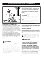
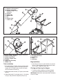
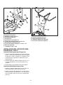
Figure 3. Install Carriage Bolts
A. Carriage Bolts, 5/16-18 x 3/4
B. Push Nuts, 5/16
C. Bracket and Mower Deck Housing
INSTALL CARRIAGE BOLTS
1. Remove and discard carriage bolt (C, Figure 2) and
locknut (B) from bracket and mower deck housing (A).
2. Secure the 5/16-18 x 3/4 carriage bolts (Figure 3) onto
bracket and mower deck housing (C) using 5/16 push
nuts (B).
Figure 2. Remove Carriage Bolt
A. Bracket and Mower Deck Housing
B. Locknut, 5/16-18
C. Carriage Bolt, 5/16-18 x 5/8
C
B
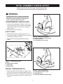
COUNTERWEIGHT INSTALLATION
1. Install front counterweight (B, Figure 1) with pin (A)
through mower hitch bracket. Bottom tabs of weight
should contact bottom of mower hitch so weight is
held in position.
2. Secure hitch pin with safety clip.
SAFETY RULES
1. Never operate mower on slopes greater than 10°.
2. Front counter weight is required when ever using rear
mounted grass collection system.
3. Always remove counterweight before removing
mower.
A
B
C
D
Figure 1. Install Mounting Plate
A. Pin
B. Front Counter Weight
C. Safety Clip
D. Mower Hitch
A
B
B
A
C

6
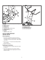
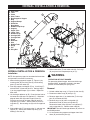
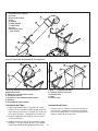
HITCH & BAG SUPPORT
INSTALLATION
Hitch Installation
1. Attach hitch assembly (B, Figure 4) to frame (A).
Secure with 3/8-16 x 1-3/8 capscrews (E), washers
(I), washers (C) and nut (D) as shown. Finger tighten
at this time.
2. Install 1/2-13 x 1-1/4 capscrew (G) through drawbar
(H) and tighten.
3. Tighten all hardware.
Bag Support Installation
1. Set bag support tube (B, Figure 5) onto hitch assem-
bly post (D).
2. Insert bag support posts (A) into hitch assembly
tubes (C). Make sure that support posts insert com-
pletely into tubes.
Figure 5. Install Bag Support
A. Bag Support Posts
B. Bag Support Tube
C. Hitch Assembly Tubes
D. Hitch Assembly Post
C
B
A
C
D
A
Figure 4. Install Hitch Assembly, without Weights
A. Frame
B. Hitch Assembly
C. Washers, 3/8
D. Locknuts, 3/8
E. Capscrews, Hex, 3/8-16 x 1-3/8
F. Locknut, 1/2-13
G. Capscrew, 1/2-13 x 1-1/4
H. Drawbar
I. Washers, 11/32 x 1-3/4
D
E
E
C
C
C
F
A
G
H
B
A
I
I

7
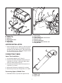
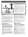
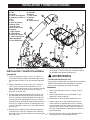
Connecting Upper & Middle Tube
1. Slide lower tube (A, Figure 8) into upper tube (B).
Figure 7. Install Lower Tube
A. Lower Chute
B. Knob, 5/16-18
C. Front Carriage Bolt, 5/16-18 x 3/4
D. Wing Nut, 5/16
E. Discharge Deflector
F. Rear Carriage Bolt, 5/16-18 x 3/4
G. Hinge Bracket
Figure 6. Install Hopper Top
A. Hopper Top
B. Washers, 1/2
C. Hair Pins
D. Bag Support Holes
E. Clevis Pins
F. Bag Support
E
A
D
B
B
C
E
D
C
F
HOPPER INSTALLATION
1. Attach the hopper top (A, Figure 6) to the bag support
(F) by inserting clevis pins (E) through the bag sup-
port holes (D) and hopper top (A). Secure with wash-
ers (B) and hair pins (C). Make sure hopper brackets
are to left of bag support brackets.
CONNECTING TUBES
Lower Tube Installation
1. Lift discharge deflector up (E, Figure 7).
2. Place the front hole of the lower chute (A) onto car-
riage bolt (C) as shown. Slide front edge of lower
chute (A) under hinge bracket (G).
3. Place the rear hole of the lower chute (A) onto car-
riage bolt (F) as shown.
4. Secure knob (B) onto carriage bolt (C) as shown.
5. Secure wing nut (D) onto carriage bolt (F) as shown.
A
B
Figure 8. Connecting Upper and Middle Tube
A. Middle Tube
B. Upper Tube
C
E
D
A
B
F
G

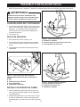
A. Notches in Bag support
B. Rubber Loop Strap
C. Bracket in Upper Tube
Assembly
D. Support
E. Upper Tube
F. Middle Tube
G. Pin
H. Rubber Strap
I. Lower Tube
8
Tube Installation
1. Set middle tube (F, Figures 9 & 10) and upper tube
(E) into bag support (D) so that bracket (C) rests in
support (D). Pull rubber loop strap (B) over upper
tube and secure into notch (A).
2. Slide middle tube assembly (E, Figure 9) onto lower
tube (F).
3. Slide middle tube (F) over lower tube (I). Pull rubber
strap (H) and place hole completely over pin (G).
B
I
A
B
A
C
C
D
D
Figure 10. Upper Tube to Bag Support Installation
A. Notches in Bag support
B. Rubber Loop Strap
C. Bracket in Upper Tube
D. Support
E. Upper Tube Assembly
F. Middle Tube
Figure 9. Upper Tube Assembly Installation (Hopper Top Not Shown for Clarity)
Figure 11. Bag Installation
A. Bag Support Hoops
B. Bag Hoops
C. Bag
D. White Bar
A
B
A
B
C
Bag Installation
1. Install bag (C, Figure 11) with white bar (C) toward
the rear. Set bag hoops (B) on bag support hoops
(A) as shown. Repeat for other side.
Closing and Opening the Hopper
1. To increase ease of opening and closing hopper
press latch located beneath center of hopper lid.
IMPORTANT: Reconnect spark plug before attempting
to start ZT Rider.
D
G
H
E
F
E
F

9
NORMAL INSTALLATION & REMOVAL
WARNING
OPERATION WITHOUT BAGGER
For operation without bagger, the mower discharge
deflector MUST be properly installed in the down
position and retained by the spring latch.
Figure 12. Normal Installation & Removal
A. Hitch Post
B. Tube
C. Posts
D. Hitch Tubes
E. Bag Support & Hopper
F. Bag
G. Support Hoops
H. White Bar
I. Bag Hoops
J. Rubber Loop Strap
K. Support
L. Upper Tube
M. Lower Tube
N. Rubber Strap
O. Carriage Bolt
P. Carriage Bolt
Q. Knob
R. Deflector
S. Slot
T. Middle Tube
U. Hinge
V. Pin
W. Wing Nut
G
F
D
J
A
Q
K
M
O
NORMAL INSTALLATION & REMOVAL
Installation
NOTE: See previous pages for more detailed installation
and operation instructions if necessary.
1. Mount the bag support & hopper (E, Figure 12) by
inserting tube (B) over hitch post (A) and inserting
posts (C) into hitch tubes (D).
2. Pivot bag support and hopper (E) up. Install bag (F)
with white bar (H) towards the rear. Set bag hoops
(I) on bag support hoops (G) as shown. Repeat for
other side.
3. Lift discharge deflector up (R). Place the front hole of
the lower tube (M) onto carriage bolt (P). Slide front
edge of lower tube (M) under hinge bracket (G).
Place the rear hole of the lower tube (M) onto car-
riage bolt (O) as shown. Secure knob (Q) onto car-
riage bolt (P). Secure wing nut (W) onto carriage bolt
(O).
4. Slide middle tube (T) into upper tube (L) and sent into
support (K). Secure with rubber loop strap (J) by
hooking it into slot (S).
Removal
1. Unhook rubber loop strap (J, Figure 12) from slot (S).
2. Disconnect rubber strap (N) from pin (V).
3. Remove upper tube (L) & middle tube (T) from sup-
port (K) and lower tube (M).
4. Remove wing nut (W) from carriage bolt (O).
Remove the knob (Q) from carriage bolt (P).
Remove the lower chute (M) from carriage bolt (P)
and carriage bolt (O). Remove lower tube (M).
IMPORTANT: See that discharge deflector (R) returns to
the DOWN position.
5. Lift and remove bag support and hopper from hitch
tubes (D) and the hitch post (A).
P
N
C
D
I
H
E
B
G
R
S
5. Slide middle tube (T) over lower tube (M). Pull strap
(N) and place hole completely over pin (V).
V
T
L
W
U

10

11
Manual Del Dueño
ZT 7000
2-HUCHA EMBOLSADORA
Modelo No.
107.24907
CAUTION: Este producto tiene un mot or
con expulsión baja el cual funciona diferente-
mente a otros motores. Antes que arranque
el motor, lea y comprenda el Manual del
Dueño.
IMPORTANT: Lea y siga todas las reglas e
intrucciones de seguridad antes de operar
este equipo.
Para obtener respuestas a qualquier pregunta
sobre este producto, llame al numéro de telé-
fono-(sin cobro) siguiente:
1-800-659-5917
Servicio de ayuda Sears Craftsman
5 am - 5 pm, Lunes a Sabado

12
ÍNDICE
GARANTÍA
Declaración de Garantía ...........................................12
Reglas de Seguridad e Información para Unidades
Montables...................................................................13
Instrucciones de operación para Embolsadora .....14
Ensamble e Instalación Inicial..................................15
Instalación y Remoción Normal ..............................19
Ferretería Identificación y
Torsión Especificación .......Interior Cubierta Trasera
Partes de Refacción............................................PTS-1
ServicioNumero deTelefono ...........Cubierta Trasera
GARANTÍA LIMITADA DEL RECOLECTOR DE CÉSPED DE CRAFTSMAN
Por un (1) año a partir de la fecha de compra, si este recolector de césped de Craftsman es mantenido, lubricado y
afinado conforme a las instrucciones de operación en el manual del propietario, Sears reparará o reemplazará sin
costo alguno cualquier parte que se encuentre defectuosa en material o mano de obra.
EL SERVICIO DE GARANTÍA ESTÁ DISPONIBLE SI RETORNA EL RECOLECTOR DE CÉSPED DE CRAFTSMAN
AL CENTRO O DEPARTAMENTO DE SERVICIO DE SEARS MÁS CERCANO A USTED EN LOS ESTADOS
UNIDOS.
PARA AVERIGUAR CUÁL ES EL SEARS MÁS CERCANO A USTED, LE ROGAMOS QUE LLAME A 1-800-MY-
HOME.
Esta garantía le otorga derechos legales específicos, pero es posible que usted tenga otros derechos, los cuales
varían de un estado a otro.
Sears, Roebuck and Co., Dept. 817WA, Hoffman Estates, IL 60179
ESTA GARANTÍA NO CUBRE:
• Artículos consumibles que se desgastan con el uso
normal, lo que incluye entre otros las aspas y los
sacos de la podadora.
• Las reparaciones necesarias por negligencia del
operador, lo que incluye entre otros, no mantener el
equipo conforme a las instrucciones comprendidas
en el manual del propietario.
• Emblosadora que se usa con fines comerciales o de
alquiler..
FERRETERIA BOLSA
Descripcion Cantidad
Embolsadora Ferretteria
Tornillo de cabeza redond, 5/16-18 x 5/8 2
Contratuerca estrellada, 5/16-18 2
Placa de montaje 1
Clavijas de seguridad 2
Arandela, 1/2 2
Horquillas 2
Contratuerca estrellada, 1/2-13 1
Tornillo hexagonal, 1/2-13 x 1-1/4 1
Arandela, 3/8 4
Contratuerca estrellada, 3/8-16 4
Tornillo hexagonal, 3/8-16 x 1-3/8 4
Tuerca De Ala, 5/16-18 1
Perilla, Plástico, 5/16-18 1
Arandela, 11/32 x 1-3/4 2
TOOLS REQUIRED
Descripcion Cantidad
9/16” Llave 2
3/4” Llave 2

13
REGLAS DE SEGURIDAD E INFORMACIÓN PARA EMBOLSADORA
Lea estas reglas de seguridad y sígalas con cuidado. No obedecer estas reglas puede resultar en la pérdida del control
sobre la unidad, lesiones severas a la persona o la muerte de usted, o espectadores, o daños a la propiedad o al equipo.
El triángulo en el texto denota precauciones o advertencias importantes que deben seguirse.
CALCOMANÍAS DE SEGURIDAD
Esta unidad fue diseñada y fabricada para ofrecerle la
seguridad y confiabilidad que usted esperaría de un líder en
la industria de la fabricación de equipos motorizados para el
exterior.
Aunque leer este manual y las medidas de seguridad que
contiene le proporcionará el conocimiento básico necesario
para operar este equipo sin percances y eficazmente,
hemos colocado varias etiquetas de seguridad en la unidad
para recordarle esta importante información mientras usted
opera su unidad.
Debe leer cuidadosamente y acatar todos los mensajes de
PELIGRO, ADVERTENCIA, PRECAUCIÓN y de instruc-
ciones en su tractor, accesorios y podadora. No seguir las
instrucciones puede resultar en lesiones personales al cuer-
po. ¡La información es para su seguridad y es importante!
Las calcomanías de seguridad aquí abajo están sobre su
producto.
Si pierde o se daña alguna de estas calcomanías, reem-
plácelas inmediatamente. Busque a su distribuidor local
para comprar repuestos.
• Conozca los controles de la unidad y cómo detenerla rápi-
damente. LEA EL MANUAL DEL OPERADOR.
• Lea y obedezca todas las calcomanías de seguridad.
• Sólo permita que un adulto responsable, que esté famil-
iarizado con las instrucciones, opere la unidad.
• Desacople el PTO. Apague el motor y permita que se
detengan todas las partes en movimiento antes de
anexar, ajustar o desconectar alguna parte del sistema de
recolección..
• Compruebe que el sistema de recolección esté fijamente
atornillado a la unidad.
• NO opere la unidad sin el recolector completo de césped
o con el deflector en su lugar.
• Apague el PTO para desactivar las aspas cuando no esté
podando el césped.
• NO pode el césped en reversa. Siempre mire hacia abajo
y hacia atrás antes de echarse en reversa y mientras lo
hace.
• NO dé la vuelta abruptamente cuando anda en reversa
junto a un edificio o algún objeto. Baje la velocidad antes
de dar la vuelta.
• NO lleve pasajeros.
• Cuando se quita el sistema de recolección de la cubierta
de la podadora, debe instalar debidamente el deflector.
• Los sacos recolectores están propensos a deteriorarse y
desgastarse durante el uso normal. Inspeccione el saco
periódicamente para comprobar que no tenga rasgaduras,
agujeros o puntos flacos y reemplácelo con un saco
nuevo que cumpla con los estándares de durabilidad del
fabricante.
• Si se atasca la podadora o se tapa el conducto del
recolector:
1. Desacople el PTO;
2. Detenga el motor y quite la llave;
3. Ponga el freno de mano y espere a que se detengan
todas las partes en movimiento.
4. Quite el objeto extraño o limpie el conducto con un
pedazo de madera antes arrancar nuevamente el motor.
NUNCA ponga las manos en el RECOLECTOR O la
caja de la PODADORA para quitar objetos atasca-
dos. La PODADORA puede girar al quitar el objeto.
• Para dar mayor estabilidad y evitar que se vuelque o
perder el control:
a. Uso una velocidad más baja en terrenos desnivelados
y al dar la vuelta en una esquina.
b. Reduzca la carga en las laderas. Se recomienda que
no llene el sistema de recolección a más de la mitad
cuando franquea una cuesta. Empiece a podar el
césped en la cuesta con el sistema de recolección
vacío.
c. Pode el césped de la cuesta de arriba hacia abajo y
viceversa; nunca no de un lado al otro.
Nunca opere en cuestas mayores a 17.6% (10°).
Calcomanías del accesorio
Estas etiquetas son fáciles de aplicar y fungirán como
constantes recordatorios visuales para usted, y otros
que puedan llegar a usar el equipo, para que sigan las
medidas de seguridad necesarias para una operación
eficaz y sin percances.
Calcomanía - ADVERTENCIA
Arroja Objetos
Número de parte - 1732819
OPERACIÓN GENERAL

14
INSTRUCCIONES DE OPERACIÓN PARA EMBOLSADORA
ANTES DE LA OPERACIÓN
Elimine del jardín todos los palos, piedras, alambres y otros
desechos que puedan quedar atrapados o ser arrojados por
las aspas de la podadora.
Compruebe la condición del césped. Si está mojado, espere
hasta más tarde. Si el césped está mojado, es probable que
el recolector de césped se atasque.
Para un embolsado eficiente, es muy importante la circu-
lación de aire abajo de la cubierta de la podadora, por el
conducto y hacia el saco.
Por esta razón, ANTES DE EMPEZAR A PODAR EL
CÉSPED asegúrese de que la parte inferior de la podadora y
la parte inferior de la tapa del recolector estén libres de
césped y desechos.
Asegúrese de que estén bien ajustados la cubierta de la
podadora, la caja del soplador, los tubos y la tapa del
recolector de césped.
PODADO DEL CÉSPED CON EL
RECOLECTOR
Siempre opere con el acelerador a toda velocidad al podar
el césped.
El césped debe podarse con frecuencia y no demasiado
corto. Si el césped está demasiado largo o frondoso podrá
ser necesario mantener la velocidad al mínimo o cortar sólo
la mitad del ancho de la podadora para evitar que se atore.
Si el césped está largo, opere la podadora en posición de
corte alto en la primera pasada, cortando de nuevo en una
posición más baja en la segunda pasada.
No abra la tapa con la podadora activada.
Si sale una gran cantidad de césped cortado por debajo de
la cubierta, es posible que esté tapado el tubo o que los
sacos estén llenos: deje de podar el césped, detenga el
montable, desacople el PTO, apague el motor y luego vacíe
el recolector o limpie el tubo.
ADVERTENCIA
SIEMPRE apague la unidad. Desacople el PTO, y
permita que se detengan todas las partes en
movimiento ANTES de desconectar o desmontar
el tubo o vaciar el recolector.SIEMPRE apague la
unidad. Desacople el PTO, y permita que se
detengan todas las partes en movimiento ANTES
de desconectar o desmontar el tubo o vaciar el
recolector..
Antes de dejar el puesto del operador por
cualquier razón, accione el freno de mano,
desacople el PTO, detenga el motor y quite la
llave.
Para reducir el peligro de un incendio, mantenga
el motor, el tractor y la podadora libre de césped,
hojas y aceite excesivo. No detenga ni estacione
el tractor sobre hojas secas, césped o materiales
combustibles.
ACCESORIOS NECESARIO
La embolsadora, de atras, se necesita pesas en el frente
de launidad 32lbs (14.5 kg). Nunca opere en cuestas
mayores a 10° .
DESPUÉS DE LA OPERACIÓN
Quite todos los desechos de la pantalla en la parte inferior
de la tapa.
Nota: La pantalla de la tapa puede quitarse par-
cialmente para limpiarla con mayor facilidad y debe hacerlo
regularmente
Debe quitar el tubos para limpiarlo.
Inspeccione los sacos para el césped para comprobar que
no esté desgastado o dañado. Asegúrese de que estén
bien ajustados la cubierta de la podadora, los tubos y la
tapa del recolector de césped.
ALMACENAR EL RECOLECTOR DE
CÉSPED
Limpie a conciencia el recolector de césped usando un
detergente suave (otros productos pueden dañar el
tubo). Quite todos los desechos de la pantalla en la parte
inferior de la tapa.
Si se ha rayado la pintura en las partes metálicas,
retóquelas con pintura, o aplique una capa delgada de
aceite para evitar que se oxiden.
Guárdela en un área seca. Séquela a conciencia antes
de guardarla por un periodo largo de tiempo. Guárdela
lejos de la humedad.
No deje el césped en los contenedores de la
embolsadora. Vacíe los contenedores después
de cada uso y antes de almacenar la unidad. No
hacerlo puede resultar en una combustión
espontánea que puede convertirse en un
incendio.
PRECAUCIÓN

15
ENSAMBLE E INSTALACIÓN INICIAL
ADVERTENCIA
Accione el freno de mano, desacople el PTO,
detenga el motor y quite la llave antes de intentar
instalar o quitar la podadora o trabajar en ella.
NOTA: En este manual, "izquierda" y "derecha" se refieren según como se vea desde la posición de operación.
INSTALE LOS PERNOS DE CARRO
1. Quitan y desechan el perno de carro (C, figura 2) y
tuerca de fijación (B) del soporte y de la cubierta del
cortacéspedes (A).
2. Asegure los pernos de 5/16-18 x 3/4 carro (A, Figura
3) sobre la cubierta de la cubierta del soporte y del
cortacéspedes (C) usando las tuercas de 5/16 empuje
(B).
LA INSTALACIÓN DEL CONTRAPESO
1. Instale el contrapeso (B, Figure 1) con el pin (A) que
pasa a traues de los dos acujeros en el soporte de la
podadoral. Las lenguetas de el peso tienen que
hacer contacto con la parte baja del soporte para
mantener el peso fijo.
2. Instsle el pin (C).
REGLAS DE SEGURIDAD
1. Nunca opere en cuestas mayores a 10°.
2. Se requiere el peso contrario delantero al siempre
usar el sistema montado atrás de la colección de la
hierba.
3. Quite siempre el contrapeso antes de quitar el cor-
tacéspedes.
A
B
C
D
Figure 1. Fronte Instalación del contrapeso
(cortacéspedes demostrado de la unidad para el
clarity)
A. Pin
B. Contra peso para el Frente
C. Pin de Seguridad
D. Soporte de la Podadora
Figura 3. Instale Los Pernos De Carro
A. Perno de Carro, 5/16-18 x 3/4
B. Empuje Las Tuercas, 5/16
C. Bracket y la cubierta
Figura 2. Quite el perno de carro
A. Bracket y la cubierta
B. Locknut, perno de carro de 5/16-18, 5/16-18
C. Perno de Carro, 5/16-18 x 5/8
C
B
A
B
B
A
C

16
INSTALACIÓN DEL SOPORTE PARA
ENGANCHE Y SACO
Instalación del oporte para Enganche
1. Instale el sistema de enganche (B, Figura 4) al basti-
dor (A). Fijelos con los tornillos de cabeza hexagonal
de 3/8-16 x 1-3/8 (E), arandelas (I), arandelas (C) en
la ordenen que se demuestra. Apriete dor mano
temporalmente.
2. Instale el tornillo de cabeza hexagonal de 1/2-13 x 1-
1/4 (G) pasándolo por la barra de enganche (H) y
apriételo.
3. Apriete todos los componentes con herramientas.
Instalación del Soporte para Saco
1. Coloque el tubo del soporte para saco (B, Figura 5)
sobre el poste del sistema de enganche (D).
2. Inserte los postes del soporte para saco (A) por los
tubos del sistema de enganche (C). Si los postes no
están alineados, ponga un calce en la conexión del
perno (E).
Figura 5. Instalación de Soporte para Saco
A. Poste de soporte para saco
B. Tubo de soporte para saco
C. Tubos del sistema de enganche
D. Poste del sistema de enganche
C
B
A
C
D
A
Figure 4. Instalación del Sistema
de Enganche sin pesos
A. Bastidor y pesos traseros
B. Sistema de enganche
C. Arandela, 3/8
D. Contratuerca estrellada, 3/8
E. Tornillo de cabeza hexagonal, 3/8-16 x 2
F. Contratuerca estrellada, 1/2-13
G. Tornillo de cabeza hexagonal, 1/2-13 x 1-1/4
H. Barra de enganche
I. Arandelas, 11/32 x 1-3/4
D
E
E
C
C
C
F
A
G
H
B
A
I
I

17
Figura 6. Instalación de Cubierta de la Tolva
A. Cubierta de la tolva
B. Arandelas, 1/2
C. Horquillas
D. Orificios de soporte para saco
E. Clavijas de seguridad
F. Soporte para saco
E
A
D
B
B
C
E
D
C
F
INSTALACIÓN DE LA TOLVA
1. Sujete la cubierta de la tolva (A, Figura 6) al soporte
para saco (F) insertando las clavijas de seguridad (E)
por los orificios del soporte para saco (D) y por la
cubierta de la tolva (A). Sujételas con las arandelas
(B) y las horquillas (C).
Figura 7. Instalación del Tubo Inferior
A. Canal inclinado
B. Knob, 5/16-18
C. Front perno de carro de, 5/16-18 x 3/4
D. Tuerca De Ala, 5/16
E. Deflector de descarga
F. Rear perno de carro de, 5/16-18 x 3/4
G. Soporte De Bisagra
A
B
Figura 8. Conectar el tubo superior y medio
A. tubo medio
B. tubo superior
C
E
D
A
B
F
G
Conectar el tubo superior y medio de la dia-
positiva del tubo
1. Más bajo (A, Figura 8) en el tubo superior (B).
TUBOS DE CONEXIÓN
Baje La Instalación Del Tubo
1. Del tubo moevva el para arriba (E, figura 7).
2. Ponga el agujero delantero del canal inclinado más
bajo (A) sobre el perno de carro (C) según lo
demostrado. Resbale el borde delantero de un canal
inclinado más bajo (A) debajo del soporte de bisagra
(G).
3. Ponga el agujero posterior del canal inclinado más
bajo (A) sobre el perno de carro (F).
4. Asegure la perilla (B) sobre el perno de carro (C).
5. Asegure la tuerca de ala (D) sobre el perno de carro
(F).

18
A. Muescas en el soporte
para saco
B. Correa de caucho
C. Clip
D. Soporte
E. Tubo superior
F. Tubo medio
G. Perno
H.Correa De goma
I. Tubo inferior
B
A
C
E
D
Figura 10. Instalación de Tubo Superior en el
Soporte para Saco
A. Muescas en el soporte para saco
B. Correa de caucho
C. Encaje en el ensamble del tubo superior
D. Soporte
E. Ensamble del tubo superior
Figura 9. Instalación de nsamble del Tubo Superior
A
B
A
B
C
Instalación del Saco
1. Instale el saco (C, Figura 11) con el blanco tubo (C)
hacia el criar. Coloque los aros del saco (B) sobre
los aros del soporte para saco (A) como se muestra.
Repita la operación en el otro lado.
D
Figura 11. Instalación del Saco
A. Aros del soporte para saco
B. Aros del saco
C. Saco
D. Blanco Tubo
Instalación del Tubo
1. Tubo medio determinado (F, Figura 9 y 10) y tubo
superior (E) en la soporte del bolso (D) de modo que
la bracket (C) se recline en el soporte (D). Tire el lazo
de la correa (B) goma y asegúrelo en la muesca (a).
2. Resbale el grdpo de tubo medio (E, figura 9) sobre
un tubo más bajo (F).
3. Resbale un tubo más bajo (F) del excedente medio
del tubo (I). Tire de la correa de goma (H) y coloque
el perno del excedente del agujero totalmente (G).
B
I
A
C
D
G
H
E
F

19
INSTALACIÓN Y REMOCIÓN NORMAL
Figura 12. Remoción e Instalación Normal
INSTALACIÓN Y REMOCIÓN NORMAL
Instalación
1. Instale el soporte para saco y la tolva (E, Figura 14)
insertando el tubo (B) sobre el poste del enganche (A)
e insertando los postes (C) en los tubos del enganche
(D).
2. Monte el soporte para saco y la tolva (E). Instale el
saco (F) con el aro de levantamiento (H) hacia el
frente. Coloque los aros del saco (I) sobre los aros del
soporte para saco (G) como se muestra. Repita la
operación en el otro lado.
3. Levante el desviador de descarga (R). Ponga el agu-
jero delantero del tubo más bajo (M) en el perno de
carro (P). Resbale el borde delantero de un tubo más
bajo (M) debajo del soporte de bisagra (G). Ponga el
agujero posterior del tubo más bajo (M) sobre el perno
de carro (O). Asegure la perilla (Q) sobre el perno de
carro (P). Asegure la tuerca de ala (W) sobre el perno
de carro (O).
4. Resbale el tubo medio (T) dentro del tubo superior (L)
y enviado en la ayuda (K). Asegure con la correa de
goma del lazo (J) enganchándola en la correa de goma
de la ranura (S).
Remoción
1. Zafe la correa de goma el lazo (J, Figura 12) de la
ranura (S).
2. Quite el tubo superior (L) y el tubo medio (T) dei
soporte (K) y baje el tubo (M).
3. Desconecte la correa de goma (N) del perno (V).
4. Quite la tuerca de ala (W) del perno de carro (O).
Quite la perilla (Q) del perno de carro (P). Quite el
canal inclinado más bajo (a) del perno de carro (P) y
del perno de carro (P). Quite un tubo más bajo (m).
Vea que la desviación de la descarga (R) vuelve a la
posición de abajo.
5. Levante y quite la ayuda y la tolva del bolso de los
tubos del tirón (D) y del poste del tirón (A).
OPERACIÓN SIN RECOLECTOR
Para operar sin embolsadora, el deflector de la podadora
DEBE ESTAR debidamente instalado en la posición
inferior y ser retenido por el pestillo de resorte.
ADVERTENCIA
G
F
D
J
A
Q
K
M
O
P
N
C
D
I
H
E
B
G
R
S
V
T
L
W
U
A. Poste del enganche
B. Tubo
C. Postes
D. Tubos del enganche
E. Soporte para Saco y
Tolva
F. Saco
G. Aros del soporte
H. Blanco Tubo
I. Aros del saco
J. Correa de caucho
K. Soporte
L. Tubo superior
M. Tubo inferior
N. Correa de caucho
O. Tuerca y tornillo de
cabeza hexagonal
P. Placa de montaje
Q. Vástago de conducto
R. Deflector
S. Ranura
T. Tubo medio
U. Bisagra
V. Perno
W. Tuerca De Ala
5. Resbale un tubo más bajo (T) del excedente medio
del tubo (M). Tire de la correa (N) y coloque el perno
del excedente del agujero totalmente (V).


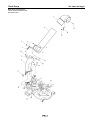
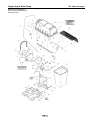
Repair Parts
PTS - 1

Chute Group
NOTE: Unless noted otherwise,
use the standard hardware torque
specification chart.
ZTS 7500 2-Bin Bagger
PTS - 2

PART NO. DESCRIPTIONREF NO QTY.
Chute Group
Footnotes
ZTS 7500 2-Bin Bagger
ELBOW, Vac Collector 7 DIA Plastic Black 1 1732359SM 1
TUBE, Clear Poly Twin Catcher 42" 2 1732809SM 1
SCREW, Machine 1/4-20 x 1/2 3004X24MA1
SCREW, Machine 1/4-20 x 1 4004X71MA1
NUT, Hex KEPS 1/4-20 Black 5 2828372SM 2
NUT, Hex Flange Toplock Small, 1/4-20 Black 6 1930642SM 2
STRAP, Hood, Rubber Black 7 2171600SM 1
HANDLE, Connect Tube 8 054416ZMA 1
PIN, Latch 9 054563MA 1
CARRIAGE BOLT, 1/4-20 x 5/8 G5 Black 10 1960252SM 1
TUBE, Boot Poly Black 11 1732060SM 1
NUT, 5/16-18 Wingnut 12 014X86MA 1
CARRIAGE BOLT, 5/16-18 x 3/4 G5 Black 13 1931333SM 2
SCREW, Truss Head Torx Drive, 5/16-18 x 7/8 Black 14 1960086SM 4
STRAP, Bagger 42" Mower Black 15 1732864ASM 2
NUT, Hex Lock ESNA Light, 5/16-18NC3B Black 16 1919438SM 4
KNOB, Internal Thread 5/16-18 23/32 Long 5 LOBE Black 17 1733098SM 1
NUT, Push PAL 5/16 DIA Thread 5/8 OD Black 18 1933988SM 2
SPACER, .344 ID x .499 19 1960236SM 1
PTS - 3

Hopper, Bag & Hitch Group
NOTE: Unless noted otherwise,
use the standard hardware torque
specification chart.
ZTS 7500 2-Bin Bagger
PTS - 4

PART NO. DESCRIPTIONREF NO QTY.
Hopper, Bag & Hitch Group
Footnotes
ZTS 7500 2-Bin Bagger
CAPSCREW, Hex Flange Whiz Lock Dog Point, 5/16-18 x 1 1 1960667SM 2
CARRIAGE BOLT, 5/16-18 x 5/8 G5 2 1931332SM 1
STRAP, Black Rubber 3 1665872SM 1
PLATE, Hopper Elbow Seal 4 1732372ASM 1
HOPPER TOP ASSEMBLY, (Includes Ref. Nos. 6 thru 19) 5 1726362SM 1
RIVET, Pop 6 1673320SM 26
WINDOW, Clear PVC 7 1679819SM 1
WASHER, 3/16 8 1910531SM 6
TOP, Hopper Black Plastic 9 1726363SM 1
SEAL, Corner, Black Rubber 10 1679568SM 2
HINGE, Hopper Top 11 1726544ASM 2
CAPSCREW, Hex Flange Whiz Lock, 1/4-20 x 3/4 12 1930594SM 4
SEAL, Center, Black Rubber 13 1679569SM 1
NUT, Hex Flange, 1/4-20 ESNA 14 1960694SM 4
STIFFENER, Front Hopper 15 1726548ASM 1
STIFFENER, Rear, 24-13/16 Long 16 1679908ASM 1
LATCH, Hopper 17 1726545ASM 1
SCREEN, 1/4 Mesh, 20 x 28 18 1716561SM 1
RETAINER, Screen, Nylon Push In Type 19 1679599SM 6
WASHER, 3/16 x 3/4 20 1960096SM 5
DECAL, Warning Objects Thrown by Mower 21 1732819SM 1
NUT, Hex Flange, 5/16-18 ESNA 22 1960686SM 1
PIPE & SHAFT ASSEMBLY, Support Grass Catcher 23 1726480ASM 2
NUT, Pipe 5/16-18 24 1726616SM 4
SPACER, 5/16 25 1667811SM 1
BRACE, Tube Center 26 1726479ASM 1
WASHER, 5/16 27 1924874SM 2
SPACER 28 1960236SM 1
PIN, Round Head Drilled, 1/2 x 1 29 1672365SM 2
SCREW, Hex Flat Head, 5/16-18 x 2 30 2860718SM 2
WASHER, 1/2 31 1960170SM 2
CLIP, Hair Pin Spring Wire, 1-5/8 32 1960074SM 2
BAG & RIM ASSEMBLY, Grass Catcher 33 1726367SM 2
EDGING, 13-1/8 Long, PVC Tube White 34 1700864SM 2
HITCH ASSEMBLY, Grass Catcher 35 1726475ASM 1
CAPSCREW, Hex Head, 3/8-16 x 1-3/8 G5 (Used on Models without Rear Weights) 36 1921968SM 2
CAPSCREW, Hex Head, 3/8-16 x 2 G5 (Used on Models with Rear Weights) 36 1923701SM 2
WASHER, 3/8 37 1922755SM 4
NUT, Hex Flange Two-Way Lock, 1/2-13 38 1930644SM 1
NUT, Hex Flange, 3/8-16 ESNA 39 1960687SM 2
CAPSCREW, Hex Head, 1/2-13 x 1-1/4 G5 40 1921176SM 1
WASHER, Flat (Used on Models without Rear Weights) 41 1960071SM 2
WASHER, Flat, 5/16 42 1960044SM 2
PTS - 5


Torque Specification Chart
FOR STANDARD MACHINE HARDWARE (Tolerance ± 20%)
Hardware
Grade
SAE Grade 2 SAE Grade 5 SAE Grade 8
Size Of
in/lbs in/lbs
in/lbs
Hardware ft/lbs Nm. ft/lbs Nm. ft/lbs Nm.
8-32
19
2.1
30
3.4
41
4.6
8-36
20
2.3
31
3.5
43
4.9
10-24
27
3.1
43
4.9
60
6.8
10-32
31
3.5
49
5.5
68
7.7
1/4-20
66
7.6 8 10.9 12 16.3
1/4-28
76
8.6 10 13.6 14 19.0
5/16-18 11 15.0 17 23.1 25 34.0
5/16-24 12 16.3 19 25.8 27 34.0
3/8-16 20 27.2 30 40.8 45 61.2
3/8-24 23 31.3 35 47.6 50 68.0
7/16-14 30 40.8 50 68.0 70 95.2
7/16-20 35 47.6 55 74.8 80 108.8
1/2-13 50 68.0 75 102.0 110 149.6
1/2-20 55 74.8 90 122.4 120 163.2
9/16-12 65 88.4 110 149.6 150 204.0
9/16-18 75 102.0 120 163.2 170 231.2
5/8-11 90 122.4 150 204.0 220 299.2
5/8-18 100 136 180 244.8 240 326.4
3/4-10 160 217.6 260 353.6 386 525.0
3/4-16 180 244.8 300 408.0
420 571.2
7/8-9 140 190.4 400 544.0 600 816.0
7/8-14 155 210.8 440 598.4 660 897.6
1-8 220 299.2 580 788.8 900 1,244.0
1-12 240 326.4 640 870.4 1,000 1,360.0
Hex Head Capscrew
Hex Nut
Lockwasher
Washer
Carriage Bolt
NOTES
1. These torque values are to be used for all hardware
excluding: locknuts, self-tapping screws, thread forming
screws, sheet metal screws and socket head setscrews.
2. Recommended seating torque values for locknuts:
a. for prevailing torque locknuts - use 65% of grade 5
torques.
b. for flange whizlock nuts and screws - use 135% of
grade 5 torques.
3. Unless otherwise noted on assembly drawings, all torque
values must meet this specification.
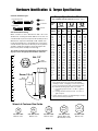
Hardware Identification & Torque Specifications
Common Hardware Types
Screw, 1/2 x 2
Body
Diameter
Body
Length
Inside
Diameter
Nut, 1/2”
No
Marks
3/8” Bolt or Nut
Wrench—9/16”
3/8
5/16” Bolt or Nut
Wrench—1/2”
5/16
1/4” Bolt or Nut
Wrench—7/16”
1/4
1/2” Bolt or Nut
Wrench—3/4”
1/2
DIA.
7/16
DIA.
7/16” Bolt or Nut
Wrench (Bolt)—5/8”
Wrench (Nut)—11/16”
Wrench & Fastener Size Guide
Standard Hardware Sizing
When a washer or nut is identified as 1/2”, this is the
Nominal size
, meaning the
inside diameter
is 1/2 inch; if a
second number is present it represent the
threads per inch
When bolt or capscrew is identified as 1/2 - 16 x 2”, this
means the
Nominal size
, or
body diameter
is 1/2 inch; the
second number represents the
threads per inch
(16 in this
example, and the final number is the
body length
of the
bolt or screw (in this example 2 inches long).
The guides and ruler furnished below are designed to
help you select the appropriate hardware and tools.
0
1/4 3/4
1/2
1
1/4 3/4
1/2
2
1/4 3/4
1/2
3
1/4 3/4
1/2
4
PTS - 6

® Registered Trademark /
TM
Trademark /
SM
Service Mark of Sears, Roebuck and Co.
® Marca Registrada /
TM
Marca de Fábrica /
SM
Marca de Servicio de Sears, Roebuck and Co.
MC
Marque de commerce /
MD
Marque déposée de Sears, Roebuck and Co. © Sears, Roebuck and Co.
Get it fixed, at your home or ours!
Your Home
For repair –in your home –of all major brand appliances,
lawn and garden equipment, or heating and cooling systems,
no matter who made it, no matter who sold it!
For the replacement parts, accessories and
owner’s manuals that you need to do-it-yourself.
For Sears professional installation of home appliances
and items like garage door openers and water heaters.
1-800-4-MY-HOME
®
(1-800-469-4663)
Call anytime, day or night (U.S.A. and Canada)
www.sears.com www.sears.ca
Our Home
For repair of carry-in items like vacuums, lawn equipment,
and electronics, call or go on-line for the location of your nearest
Sears Parts & Repair Center.
1-800-488-1222
Call anytime, day or night (U.S.A. only)
www.sears.com
To purchase a protection agreement (U.S.A.)
or maintenance agreement (Canada) on a product serviced by Sears:
1-800-827-6655 (U.S.A.) 1-800-361-6665 (Canada)
Para pedir servicio de reparación
a domicilio, y para ordenar piezas:
1-888-SU-HOGAR
SM
(1-888-784-6427)
Au Canada pour service en français:
1-800-LE-FOYER
MC
(1-800-533-6937)
www.sears.ca
-
 1
1
-
 2
2
-
 3
3
-
 4
4
-
 5
5
-
 6
6
-
 7
7
-
 8
8
-
 9
9
-
 10
10
-
 11
11
-
 12
12
-
 13
13
-
 14
14
-
 15
15
-
 16
16
-
 17
17
-
 18
18
-
 19
19
-
 20
20
-
 21
21
-
 22
22
-
 23
23
-
 24
24
-
 25
25
-
 26
26
-
 27
27
-
 28
28
-
 29
29
-
 30
30


Simplicity ZTS-7500 Manual de usuario
- Categoría
- Cortadoras de césped
- Tipo
- Manual de usuario
- Este manual también es adecuado para
en otros idiomas
- English: Simplicity ZTS-7500 User manual
Artículos relacionados
Otros documentos
-
Craftsman 917248951 El manual del propietario
-
-
-
-
-
-
-
Craftsman 19A30003799 El manual del propietario
-
MTD 19A30018799 El manual del propietario
-