
Date Issued: 04/18/16 IS-43922-US
SEE OTHER SIDE FOR SPANISH TRANSLATIONS.
VEA EL OTRO LADO DE TRADUCCIONES AL ESPAÑOL.
We’re here to help 866-558-5706
Hrs: M-F 9am to 5pm EST
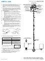
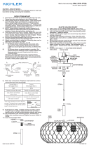
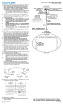
1) Pass fixture wire thru Body Tube. Thread tube onto threaded
nipple on bottom of fixture and tighten to secure.
2) Pass fixture wire and ground wire thru desired amount of
stems D & E and thread together using supplied nipples.
NOTE: Use a drop of Thread compound (supplied) on the
threads.
3) Thread Swivel onto stems securely. Pass threaded Swivel,
wire, ground wire thru hole in canopy. Place lockwasher
onto end of threaded nipple protruding from inside canopy.
Thread hexnut onto threaded nipple protruding from inside
canopy. Tighten to secure Swivel.
4) Rotate the arms into the correct location as shown.
5) TURN OFF POWER.
a) IMPORTANT: Before you start, NEVER attempt any
work without shutting off the electricity until the work is
done.
b) Go to the main fuse, or circuit breaker, box in your
home. Place the main power switch in the “OFF”
position.
c) Unscrew the fuse(s), or switch “OFF” the circuit breaker
switch(s), that control the power to the fixture or room
that you are working on.
d) Place the wall switch in the “OFF” position. If the fixture
to be replaced has a switch or pull chain, place those in
the “OFF” position.
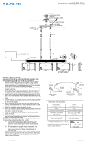
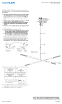
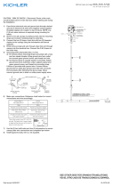
6) Find the appropriate threaded holes on mounting strap. As-
semble mounting screws into threaded holes.
7) Attach mounting strap to outlet box. Mounting strap can be
adjusted to suit position of fixture.
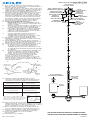
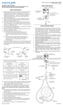
8) Grounding instructions: (See Illus. A or B)
A) On fixtures where mounting strap is provided with a
hole and two raise dimples. Wrap ground wire from
outlet box around green ground screw, and thread into
hole.
B) On fixtures where a cupped washer is provided. Put
ground wire from outlet box under cupped washer
and green ground screw and thread screw into hole in
mounting strap.
If fixture is provided with ground wire. Connect fixture
ground wire to outlet box ground wire with wire connector,
after following the above steps. Never connect ground wire
to black or white power supply wires.
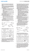
9) Make wire connections. Reference chart below for correct
connections and wire accordingly.
10) Push fixture to ceiling, carefully passing mounting screws
through holes in canopy. Make sure all wires are inside
canopy and do not get pinched between canopy and
ceiling.
11) Thread lockup knobs onto mounting screw and tighten to
secure fixture to ceiling.
12) Place glass over socket and take the glass retainer and
thread onto the socket to secure glass in place..
13) Insert recommended bulbs. (Not included).
14) Installation is now complete.
GREEN GROUND
SCREW
CUPPED
WASHER
OUTLET BOX
GROUND
FIXTURE
GROUND
DIMPLES
WIRE CONNECTOR
OUTLET BOX
GROUND
GREEN GROUND
SCREW
FIXTURE
GROUND
A
B
Connect Black or
Red Supply Wire to:
Connect
White Supply Wire to:
Black White
*Parallel cord (round & smooth) *Parallel cord (square & ridged)
Clear, Brown, Gold or Black
without tracer
Clear, Brown, Gold or Black
with tracer
Insulated wire (other than green)
with copper conductor
Insulated wire (other than green)
with silver conductor
*Note: When parallel wires (SPT I & SPT II)
are used. The neutral wire is square shaped
or ridged and the other wire will be round in
shape or smooth (see illus.)
Neutral Wire
OUTLET BOX
CAJA DE SALIDA
WIRE CONNECTOR(S)
CONECTOR DE CABLE(S)
STRAP
MOUNTING SCREW(S)
CORREA DE
TORNILLO
DE MONTAJE
MOUNTING STRAP
CORREA DE MONTAJE
MOUNTING SCREW
TORNILLO
DE MONTAJE
HEXNUT
TUERCA HEXAGONAL
LOCKWASHER(S)
ARANDELA
DE SEGURIDAD
LOCK-UP KNOB(S)
PERILLA DE BLOQUEO(S)
SWIVEL
GIRAR
SMALL
THREADED NIPPLE
NIPLE ROSCADO
PEQUEÑO
E
D
BODY TUBE
CUERPO
DEL TUBO
GLASS
VIDRIO
GLASS RETAINER
RETENEDOR DE VIDRIO

Date Issued: 04/18/16 IS-43922-US
SEE OTHER SIDE FOR ENGLISH TRANSLATIONS.
VEA EL OTRO LADO DE TRADUCCIONES AL INGLÉS.
We’re here to help 866-558-5706
Hrs: M-F 9am to 5pm EST
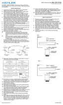
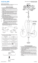
1) Pase el cable del artefacto a través del tubo del cuerpo.
Enrosque el tubo en el niple roscado en la parte inferior del
artefacto y apriete para asegurar.
2) Pase el cable del artefacto y el cable de tierra a través de la
cantidad deseada de los vástagos D y E, y enrosque juntos
usando los niples suministrados. NOTA: Use una gota del
compuesto para rosca (suministrado) en las roscas.
3) Enrosque de manera segura la unión giratoria en los vásta-
gos. Pase la unión giratoria roscada, el cable y el cable
de tierra, a través del agujero en el escudete. Coloque la
arandela de seguridad en el extremo del niple roscado que
sobresale desde dentro del escudete. Enrosque la tuerca
hexagonal en el niple roscado que sobresale desde dentro
del escudete. Apriete para asegurar la unión giratoria.
4) Rote los brazos en el lugar correcto como se indica.
5) APAGUE LA ALIMENTACIÓN ELÉCTRICA.
IMPORTANTE: Antes de comenzar, NUNCA trate de
trabajar sin antes desconectar la corriente hasta que el
trabajo se termine.
a) Vaya a la caja principal de fusibles, o interruptor o caja
de circuitos de su casa. Coloque el interruptor de la
corriente principal en posición de apagado “OFF”.
b) Desatornille el (los) fusible (s), o coloque el interruptor
o interruptores del breaker en posición de apagado
“OFF”, que controla (n) la corriente hacia el artefacto o
habitación donde está trabajando.
c) Coloque el interruptor de pared en posición de
apagado “OFF”. Si el artefacto que se va a
reemplazar tiene un interruptor o cadena que se jala,
colóquelos en la posición de apagado “OFF”.
6) Encuentre los agujeros roscados apropiados en la
abrazadera de montaje. Ensamble los tornillos de montaje
en los agujeros roscados.
7) Unir la abrazadera de montaje a la caja de conexiones.
(No se proveen tornillos). La abrazadera de montaje puede
ajustarse para acomodar la posición del artefacto.
8) Instrucciones para poner a tierra: (Ver Ilustraciones A o B).
A) En artefactos donde se suministra la abrazadera
de montaje con un agujero y dos depresiones
onduladas. Envuelva el conductor de tierra de la caja
de salida alrededor del tornillo de tierra verde y atornille
en el agujero.
B) En artefactos donde se suministra una arandela cónca
va. Fije el conductor de tierra de la caja de salida
debajo de la arandela cóncava y el tornillo de tierra
verde y enrosque en la abrazadera de montaje.
Si se suministra el artefacto con conductor de tierra.
Conecte el conductor de tierra del artefacto al
conductor de tierra de la caja de salida con conector de
tierra después de seguir los pasos anteriores. Nunca co-
necte el conductor de tierra a los alambres de alimentación
eléctrica negros o blancos.
9) Haga las conexiones de alambres (No se provee
conectores). Vea la tabla de referencia de abajo para las
conexiones correctas y los alambres correspondientes.
10) Suba el artefacto al techo pasando cuidadosamente los
tornillos de montaje a través de los agujeros en el escudete.
Asegúrese que todos los cables estén dentro del escudete y
que no se pellizquen entre el escudete y el techo.
11) Pomos de bloqueo en el tornillo de montaje del hilo de
rosca y se aprieta a Asegure el luminario hasta el techo.
12) Colocar el vaso en la base y tomar el sello del vidrio y el
tornillo en el zócalo para asegurar vidrio en su lugar.
13) Inserte las bombillas o focos recomendados.
(No se incluyen)
14) La instalación está completa.
OUTLET BOX
CAJA DE SALIDA
WIRE CONNECTOR(S)
CONECTOR DE CABLE(S)
STRAP
MOUNTING SCREW(S)
CORREA DE
TORNILLO
DE MONTAJE
MOUNTING STRAP
CORREA DE MONTAJE
MOUNTING SCREW
TORNILLO
DE MONTAJE
HEXNUT
TUERCA HEXAGONAL
LOCKWASHER(S)
ARANDELA
DE SEGURIDAD
LOCK-UP KNOB(S)
PERILLA DE BLOQUEO(S)
SWIVEL
GIRAR
SMALL
THREADED NIPPLE
NIPLE ROSCADO
PEQUEÑO
E
D
BODY TUBE
CUERPO
DEL TUBO
GLASS
VIDRIO
GLASS RETAINER
RETENEDOR DE VIDRIO
ARANDELA
CONCAVA
TIERRA DE LA
CAJA DE SALIDA
TORNILLO DE TIERRA,
VERDE
DEPRESIONES
TIERRA
ARTEFACTO
CONECTOR DE ALAMBRE
TIERRA DE LA
CAJA DE SALIDA
TORNILLO DE TIERRA,
VERDE
TIERRA
ARTEFACTO
A
B
Conectar el alambre de
suministro negro o rojo al
Conectar el alambre de
suministro blanco al
Negro Blanco
*Cordon paralelo (redondo y liso)
*Cordon paralelo (cuadrado y estriado)
Claro, marrón, amarillio o negro
sin hebra identificadora
Claro, marrón, amarillio o negro
con hebra identificadora
Alambre aislado (diferente del verde)
con conductor de cobre
Alambre aislado (diferente del
verde) con conductor de plata
*Nota: Cuando se utiliza alambre paralelo
(SPT I y SPT II). El alambre neutro es de forma
cuadrada o estriada y el otro alambre será de
forma redonda o lisa. (Vea la ilustracíón).
Hilo Neutral
-
 1
1
-
 2
2


Kichler Lighting 43922OZ Manual de usuario
- Tipo
- Manual de usuario
- Este manual también es adecuado para
en otros idiomas
- English: Kichler Lighting 43922OZ User manual
Artículos relacionados
-
 Kichler Lighting 43927NI Manual de usuario
-
 Kichler Lighting 43925OZ Manual de usuario
-
 Kichler Lighting 42494CH Manual de usuario
-
Kichler Lighting 43954OZ Manual de usuario
-
 Kichler Lighting 43958NBR Manual de usuario
-
 Kichler Lighting 43896OZ Manual de usuario
-
 Kichler Lighting 42893CH Manual de usuario
-
 Kichler Lighting 43871OZ Manual de usuario
-
 Kichler Lighting 43794BK Manual de usuario
-
 Kichler Lighting 43793BK Manual de usuario


