La página se está cargando...

CAUTION – RISK OF SHOCK – Disconnect Power at the main
circuit breaker panel or main fuse box before starting and during
the installation.
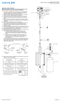
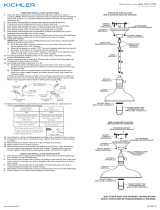
1) Pass fixture electrical wire and ground wire through desired
amount of stems D & E and screw together using supplied
threaded nipples into coupler on top of fixture. NOTE: one
(1) 12 inch stem minimum is required during mounting for
safety.
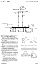
2) Screw in two (2) canopy mounting screws into the mounting
strap and connect mounting strap to outlet box.
3) Connect the two (2) loops, chain link with two (2) threaded
nipples to the canopy using the lockwasher and hexnut
supplied.
4) Route wires and ground wire through chain link and through
canopy into the electrical box. Connect the D & E stems to
the lower loop.
5) Grounding instructions: (See Illus. A or B).
A) On fixtures where mounting strap is provided with a hole
and two raised dimples. Wrap ground wire from outlet
box around green ground screw, and thread into hole.
B) On fixtures where a cupped washer is provided. Attach
ground wire from outlet box under cupped washer and
green ground screw, and thread into mounting strap.
If fixture is provided with ground wire. Connect fixture
ground wire to outlet box ground wire with wire connector
(not provided.) after following the above steps. Never
connect ground wire to black or white power supply wires.
6) Make wire connections. Reference chart below for correct
connections and wire accordingly.
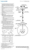
7) Use the (2) two ball knobs and two (2) lockwashers to secure
canopy after wire connections are completed per below.
8) Install approved bulb, item C, not supplied.
GREEN GROUND
SCREW
CUPPED
WASHER
OUTLET BOX
GROUND
FIXTURE
GROUND
DIMPLES
WIRE CONNECTOR
OUTLET BOX
GROUND
GREEN GROUND
SCREW
FIXTURE
GROUND
A
B
Connect Black or
Red Supply Wire to:
Connect
White Supply Wire to:
Black White
*Parallel cord (round & smooth) *Parallel cord (square & ridged)
Clear, Brown, Gold or Black
without tracer
Clear, Brown, Gold or Black
with tracer
Insulated wire (other than green)
with copper conductor
Insulated wire (other than green)
with silver conductor
*Note: When parallel wires (SPT I & SPT II)
are used. The neutral wire is square shaped
or ridged and the other wire will be round in
shape or smooth (see illus.)
Neutral Wire
Date Issued: 05/30/2017 IS-43794-US
SEE OTHER SIDE FOR SPANISH TRANSLATIONS.
VEA EL OTRO LADO DE TRADUCCIONES AL ESPAÑOL.
We’re here to help 866-558-5706
Hrs: M-F 9am to 5pm EST
MOUNTING SCREWS
OUTLET BOX
MOUNTING STRAP
STRAP MOUNTING SCREWS
WIRE CONNECTORS
(2) LOCK-UP KNOBS
(2) LOCKWASHER
LOOP
NIPPLE
LOOP
LOCKWASHER
HEXNUT
CANOPY
CHAIN LINK
D
E
C
BULB NOT
INCLUDED
E
**MINIMUM OF ONE 12" STEM
REQUIRED FOR MOUNTING.**

PRECAUCIÓN – RIESGO DE DESCARGA ELÉCTRICA – Desco-
necte la electricidad en el panel principal del interruptor au-
tomático o caja principal de fusibles antes de comenzar y
durante la instalación.
1) Pase el cable del artefacto y el conductor de tierra a través
de la cantidad deseada de los vástagos D y E, y enrósque
los juntos, usando los niples roscados provistos, en el
acoplador en la parte superior del artefacto. NOTA: se
requiere un mínimo de un (1) vástago de 12 pulgadas
durante el montaje por razones de seguridad.
2) Atornille dos (2) tornillos de montaje del escudete en la
abrazadera de montaje y conecte ésta a la caja de salida.
3) Conecte los dos (2) anillos, eslabón de cadena con los dos
(2) niples roscados al escudete, usando la arandela de
seguridad y la tuerca hexagonal provistas.
4) Encamine los cables y el conductor a tierra a través del
eslabón de cadena y del escudete hacia la caja eléctrica.
Conecte los vástago D y E al anillo inferior.
5) Instrucciones de conexión a tierra solamente para los
Estados Unidos. (Vea la ilustracion A o B).
A) En las lámparas que tienen el fleje, de montaje con un
agujero y dos hoyuel os realzados. Enrollar el alambre a
tierra de la caja tomacorriente alrededor del tornillo
verde y pasarlo por el aquiero.
B) En las lámparas con una arandela acopada. Fijar el
alambre a tierra de la caja tomacorriente del ajo de la
arandela acoada y tornillo verde, y paser por el fleje de
montaje.
Si la lámpara viene con alambre a tierra. Conecter el alambre a
tierra de la lámpara al alambre a tierra de la caja tomacorriente
con un conector de alambres (no incluido) espués de seguir los
pasos anteriores. Nunca conectar el alambra a tierra a los
alambres eléctros negro o blanco.
6) Haga les conexiones de los alambres (no se proveen los
connectores.) La tabla de referencia de abajo indica las
conexiones correctas y los alambres correspondientes.
7) Use las (2) dos perillas redondas y dos (2) arandelas de
seguridad para asegurar el escudete después de completar
las conexiones de cables como se indica más abajo.
8) Instale la bombilla aprobada, ítem C, no provista.
ARANDELA
CONCAVA
TIERRA DE LA
CAJA DE SALIDA
TORNILLO DE TIERRA,
VERDE
DEPRESIONES
TIERRA
ARTEFACTO
CONECTOR DE ALAMBRE
TIERRA DE LA
CAJA DE SALIDA
TORNILLO DE TIERRA,
VERDE
TIERRA
ARTEFACTO
A
B
Conectar el alambre de
suministro negro o rojo al
Conectar el alambre de
suministro blanco al
Negro Blanco
*Cordon paralelo (redondo y liso)
*Cordon paralelo (cuadrado y estriado)
Claro, marrón, amarillio o negro
sin hebra identificadora
Claro, marrón, amarillio o negro
con hebra identificadora
Alambre aislado (diferente del verde)
con conductor de cobre
Alambre aislado (diferente del
verde) con conductor de plata
*Nota: Cuando se utiliza alambre paralelo
(SPT I y SPT II). El alambre neutro es de forma
cuadrada o estriada y el otro alambre será de
forma redonda o lisa. (Vea la ilustracíón).
Hilo Neutral
Date Issued: 05/30/2017 IS-43794-US
SEE OTHER SIDE FOR ENGLISH TRANSLATIONS.
VEA EL OTRO LADO DE TRADUCCIONES AL INGLÉS.
We’re here to help 866-558-5706
Hrs: M-F 9am to 5pm EST
TORNILLO DE MONTAJE
CAJA DE SALIDA
ABRAZADERA DE MONTAJE
TORNILLOS DE MONTAJE DE LA ABRAZADERA
CONECTORES DE ALAMBRE
(2) PERILLAS DE SUJECIÓN
(2) ARANDELA DE SEGURIDAD
ANILLO
RACOR
ANILLO
ARANDELA DE SEGURIDAD
TUERCA HEXAGONAL
ESCUDETE
ESLABÓN DE CADENA
D
E
C
Bombilla
(No se incluye)
E
**Mínimo de un tallo de 12 "
requerido para el montaje.**
1/2