Craftsman 139.53991 El manual del propietario
- Categoría
- Abridor de puerta de garage
- Tipo
- El manual del propietario
Este manual también es adecuado para

Owner's Manual/Manual Del Propietario
1/2 HP
GARAGE DOOR OPENER
ABRIDOR DE PUERTA DE COCHERA
For Residential Use Only/Sblo para uso residencial
Model/Modelo 139.53991
rn
z
Q
"I-
m
o_
CAUTION"
Read and follow all safety rules
and operating instructions before
first use of this product.
PRECAUCION:
Leer y seguir todas las reglas de
seguridad y las instrucciones de
operacibn antes de usar este
producto por primera vez.
Fasten the manual near the garage
door after installation.
Guardar este manual cerca de la
puerta del garaje.
c(_)us
Sears, Roebuck and Co., Hoffman Estates, IL 60179 U.S.A
www.sears.com/craftsman

TABLE OF CONTENTS
Introduction 2.7
Safety symbol and signal word review ........................ 2
Preparing your garage door ........................................ 3
Tools needed ............................................................... 3
Planning .................................................................. 4-5
Carton inventory .......................................................... 6
Hardware inventory ..................................................... 7
Assembly 8.11
Assemble the rail ..................................................... 8-9
Fasten rail to motor unit and install trolley ................ 10
Attach rail brackets .................................................... 11
Installation 11.27
Installation safety instructions .................................... 11
Determine the header bracket location ................ 12-13
Install the header bracket .......................................... 14
Attach the rail to the header bracket ......................... 15
Install the safety reversing sensor ....................... 16-18
Position the opener ................................................... 19
Hang the opener ....................................................... 20
Install the door control and connect wiring ............... 21
Electrical requirements .............................................. 22
Complete the sensor installation ............................... 22
Install the lights and lens ........................................... 23
Attach the emergency release rope and handle .......23
Fasten the door bracket ....................................... 24-25
Connect door arm to trolley ................................. 26-27
Adjustment Section 28.30
Adjust the travel limits ............................................... 28
Adjust the force ......................................................... 29
Test the safety reversing sensor ............................... 30
Test the safety reverse system ................................. 30
Operation 31.34
Operation safety instructions ..................................... 31
Using your garage door opener ................................ 31
Using the wall-mounted Door Control ....................... 32
To open the door manually ........................................ 32
Care of your garage door opener .............................. 33
Having a problem? .................................................... 34
Programming 35.36
To add a hand-held remote control ........................... 35
To erase all codes ..................................................... 35
Multi-Function Remotes ............................................ 35
To add or change a Keyless Entry PIN ..................... 36
Repair Parts 37.38
Rail assembly parts ................................................... 37
Installation parts ........................................................ 37
Motor unit assembly parts ......................................... 38
Accessories 39
Warranty
Service Numbers
39
Back cover
INTRODUCTION
Safety Symbol
and Signal Word Review
This garage door opener has been designed and tested to offer safe service provided it is installed, operated,
maintained and tested in strict accordance with the instructions and warnings contained in this manual.
Mechanical
Electrical
When you see these Safety Symbols and Signal
Words on the following pages, they will alert you to
the possibility of serious injury or death if you do
not comply with the warnings that accompany them.
The hazard may come from something mechanical
or from electric shock. Read the warnings carefully.
When you see this Signal Word on the following
pages, it will alert you to the possibility of damage to
your garage door and/or the garage door opener if
you do not comply with the cautionary statements
that accompany it. Read them carefully.

Preparing your garage door
Before you begin:
• Disable locks.
• Remove any ropes connected to garage door.
• Complete the following test to make sure your
garage door is balanced and is not sticking or
binding:
1. Lift the door about halfway as shown. Release
the door. If balanced, it should stay in place,
supported entirely by its springs.
2. Raise and lower the door to see if there is any
binding or sticking.
If your door binds, sticks, or is out of balance, call
a trained door systems technician.
To prevent possible SERIOUSINJURYORDEATH:
• ALWAYScall a trained door systems technician if
garagedoor binds, sticks, or is out of balance.An
unbalancedgarage door may not reversewhen
required.
• NEVERtry to loosen, move or adjust garagedoor, door
springs, cables,pulleys, brackets or their hardware,all
of which are under EXTREMEtension.
• DisableALL locks and removeALL ropes connectedto
garagedoor BEFOREinstalling and operating garage
door opener to avoid entanglement.
To prevent damageto garage door and opener:
• ALWAYSdisable locks before installing and operating
the opener.
• ONLYoperategaragedoor opener at 120V,60 Hzto
avoid malfunction and damage.
Sectional Door
One-Piece Door
Tools needed
During assembly, installation and adjustment of the
opener, instructions will call for hand tools as
illustrated below.
Stepladder
Drill
Tape Measure
3/1_
and 5/32" Drill Bits
Pencil
Wire Cutters
Pliers
Screwdriver
Hack Saw
Claw Hammer
1/2" x 7/16" Box Wrench

Planning
Identify the type and height of your garage door.
Survey your garage area to see if any of the
conditions below apply to your installation. Additional
materials may be required. You may find it helpful to
refer back to this page and the accompanying
illustrations as you proceed with the installation of
your opener.
Depending on your requirements, there are several
installation steps which may call for materials or
hardware not included in the carton.
• Installation Step 1 - Look at the wall or ceiling
above the garage door. The header bracket must
be securely fastened to structural supports.
• Installation Step 6 - Do you have a finished ceiling
in your garage? If so, a support bracket and
additional fastening hardware may be required.
• Installation Step 4 - Depending upon garage
construction, extension brackets or wood blocks
may be needed to install sensors.
• Installation Step 4 - Alternate floor mounting of the
safety reversing sensor will require hardware not
provided.
Do you have an access door in addition to the
garage door? If not, Model 53702 Emergency Key
Release is required. See Accessories page.
Look at the garage door where it meets the floor.
Any gap between the floor and the bottom of the
door must not exceed 1/4". Otherwise, the safety
reversal system may not work properly. See
Adjustment Step 3. Floor or door should be
repaired.
SECTIONAL DOOR INSTALLATIONS
• Do you have a steel, aluminum, fiberglass or glass
panel door? If so, horizontal and vertical reinforce-
ment is required (Installation Step 12).
• The opener should be installed above the center of
the door. If there is a torsion spring or center
bearing plate in the way of the header bracket, it
may be installed within 4 feet to the left or right of
the door center. See Installation Steps 1 and 12.
• If your door is more than 7 feet high, see rail
extension kits listed on Accessories page.
SECTIONAL DOOR INSTALLATION
Horizontal and vertical reinforcement
is needed for lightweight garage doors
(fiberglass, steel, aluminum, door with
glass panels, etc.). See page 24 for details.
Header Wall
Torsion
Spring
Rail
OR
FINISHED CEILING
Support bracket &
fastening hardware
is required.
See page 20
Extension
Spring
Motor unit
Wall-
mounted
Door
Control
,Safety Reversing Sensor
Gap between floor
and bottom of door
must not exceed 1/4"
Safety
Reversing
Sensor
Door
O
Header
Bracket
J
CLOSED POSITION
Rail Rail Assembly
Bracket
Straight
Arm
Emergency
-- Release
Rope & Handle
Curved
Door
Door
Arm
Bracket

Planning (Continued)
ONE-PIECE DOOR INSTALLATIONS
• Generally, a one-piece door does not require
reinforcement If your door is lightweight, refer to
the information relating to sectional doors in
Installation Step 12
• Depending on your door's construction, you may
need additional mounting hardware for the door
bracket (Step 12)
Without a properly working safety reversal system,
persons (particularly small children) could be
SERIOUSLYINJUREDor KILLED bya closing garage
door.
• Thegap betweenthe bottom of the garage door and
the floor MUSTNOTexceed1/4". Otherwise,the safety
reversalsystem may notwork properly.
• Thefloor or the garage door MUSTbe repaired to
eliminate the gap.
ONE-PIECE DOOR WITHOUT TRACK FINISHED CEILING_
Support bracket \_\ "-_r _
& fastening _\ _/
hardware is required. \'_\
__ Header Wall
/II-r__ _,, Mo,oron,
/__ Wall-mounted
/11 --71__tl I_ --- °°°'°°°'_°'.
/ I I R II %=11 _1 I Access /
/ _-_ II I_-L!i_IIDoor _ BRrailcket
o
/ 114 I I I I_ I I Door
/ 1_ ____ Bracket
| I_L-_,___ Safety Reversing
_L _ _ Gap between floor Sensor
CLOSED POSITION
Rail Assembly
Safety Reversing and bottom of door
Sensor must not exceed 1/4"
Trolley
Straight Curved
Garage Door Door
Door Arm Arm
Emergency
Release
Rope & Handle
ONE-PIECE DOOR WITH TRACK
_,,, _eve_ing
Reversing Sensor must not exceed 1/4" i
Garage
Door
CLOSED POSITION
Rail Trolley
Bracket
I
Curved _L_ I
Bracket Door Arm _-_.._
Rail
Assembly
,# I I
....... I.... _.,,, I
I
Door i
Bracket Straight 1
Door _
Arm
Emergency Release
Rope & Handle

Carton Inventory
Your garage door opener is packaged in one carton
which contains the motor unit and the parts illustrated
below. Note that accessories will depend on the
model purchased. If anything is missing, carefully
check the packing material. Parts may be stuck in the
foam. KEEP THE FOAM INTACT (see page 10.)
Hardware for assembly and installation is shown on
the next page. Save the carton and packing material
until installation and adjustment is complete.
Premium Control Console
SECURITY÷
Three-Function Remote Control
with Visor Clip (2)
Sprocket
Coupling
Light Lens
Rail Support
graces_
SECURITY÷
Keyless Entry
Rail
Assembly
2-Conductor Bell Wire
White & White/Red
HeadedRail
Brackets
Header Bracket
Hanging Brackets
with attached 2-Conductor
White & White/Black Bell Wire
Door Bracket
Safety Reversing Sensor
Mounting Bracket (2)
Trolley
Straight Door
Arm Section
Curved Door
Arm Section
Safety Labels I
and
Literature
''1

Hardware Inventory
Separate all hardware and group as shown below for the assembly and installation procedures.
ASSEMBLY HARDWARE
,,,,,,,,,1 @
Bolt 1/4" - 20 x 5/8" Lock Nut
1/4-20xl-3/4" (8) Hex Bolt (4) 1/4"-20 x 7/16 (12)
Sprocket Coupling Sleeve
INSTALLATION HARDWARE
©
Carriage Bolt Wing Nut (2) Ring
1/4"-20xl/2" (2) Fastener (3)
llllllllll_
Lag Screw
5/16"-9xl-5/8" (2)
111111111111_
Lag Screw
5/16"-18xl -7/8" (2)
Carriage Bolt
5/16 "-18x2-1/2" (2)
Clevis Pin
5/16"x2-3/4" (1)
1111111111_
Hex Bolt
5/16"-18x7/8" (4)
@
Nut 5/16"-18 (6)
@
Lock Washer 5/16" (6)
_ IIlllllllllllllllllllllll_
Screw
6ABx1-1/4" (2)
o)
Dry Wall Anchors (2)
Clevis Pin
5/16"x1" (1)
Handle
Insulated
Staples (30)
_ IIlllllllllllllllllll
Screw 6-32xl" (2)
Rope
o_
Clevis Pin
5/16"x1-1/4" (1)

ASSEMBLY STEP 1
Assemble the Rail
To avoid installation difficulties, do not run the
garage door opener until instructed to do so.
1. Turn the opened rail carton upside down and
empty its contents onto a level work surface.
2. Unfold the rails, taking care to avoid kinking the
screw rod joints.
3. Rotate the rail sections so that the flat side is down
and the screw side is up for all three lengths. Keep
it clean and free of debris while you are working.
Rail
Support
Braces --
Straight
Door Arm
Remove
Cardboard Packing
Center
Rail
Trolley Rack
Rail Assembly I
Carton / /"
Remove --
Cardboard
Packing
Extend
End Rails
Outward
Rail Assembly
Hardware Bag
Chassis Assembly
Hardware Bag
Sprocket End Rail
NOTE: During assembly, avoid pulling the rail section
housing the trolley rack away from the screw rod.
The rack is factory set about 9" from the end of the
screw rod to the center of the rack.
If the plastic liner slides part way out during
assembly, simply push it back in.
Rail
Sprocket
Center Rail
Trolley Rack
Door End Rail

Assemble the Rail (Continued)
4. Beginning with the sprocket end, straighten the
three rail sections so that the screw rod is in a
straight line at the joints. (Avoid handling the joints,
which may have sharp edges.)
5. Carefully slide the pins at the top edge of the rail
into the openings on the adjacent rail. It is
essential that the rail assembly be on a level
surface to achieve proper alignment and to
avoid damage to the pins.
6. Insert two 1/4"-20xl-3/4" bolts through the center
holes of a brace, and place its open length against
the rail at the joint, aligning the holes as shown.
Position another brace on the opposite side of the
rail over the bolts, add 1/4"-20 lock nuts, and hand
tighten. Insert two additional bolts and hand
tighten.
7. Keeping the rail straight and on a level surface,
grasp the screw rods on each side of the
remaining joint and pivot into a straight line.
Repeat steps 5 and 6.
8. With a 7/16 wrench, tighten bolts until snug,
beginning with the center holes. Do not
overtighten.
D
HARDWARE SHOWN ACTUAL SIZE
lllllllll}
Bolt Lock Nut
1/4-20xl-3/4" (8) 1/4" - 20
Sprocket End
(Back)
Rail
Support
Brace
Door End
(Front)
Lock Alignment
Nuts Hole
Slide end rail
toward center rail
Rail
Support
Brace
Lock
Nuts
Rail Pin
Center Rail
1!4x20x1-3/4"
Bolts
Alignment
Hole
Slide end rail
f toward center rail

ASSEMBLY STEP 2
Fasten the Rail To the Motor Unit
and Install the Trolley
NOTE: To aid in assembly and installation, replace
the foam packing around the motor un#. Remove #
after Installation Step 5.
• Working on a level surface, align the rail assembly
with the motor unit, as shown.
• Slip the coupling over the rail sprocket.
• Slide the rail through the motor unit bracket until
the coupling fits securely over the motor unit
sprocket.
• Align the two bolt holes in the rail with those in the
motor unit bracket. Insert two 1/4"-20x5/8" hex
bolts and lock nuts. Tighten securely with a 7/16"
socket wrench.
• Slide the trolley onto and along the bottom of the
rail until it snaps firmly in place. Be certain to
install it facing correctly: the trolley release
arm must be horizontal (lock position), with its
arrow pointed away from the motor unit.
HARDWARE SHOWN ACTUAL SIZE
Lock Nut
Hex Bolt 1/4"- 20
1/4" - 20 x 5/8"
,lllllll
©
Motor Unit
Sprocket
Motor Unit
Bracket
Rail
Assembly
Coupling
Rail
Sprocket
Foam Packaging
Hex Bolts
1/4"-20x5/8"
Trolley
Release arm
Arrow must point
toward garage door
10

ASSEMBLY STEP 3
Attach the Rail Brackets
• Align rail brackets to end of rail assembly, as
shown.
• Insert two 1/4"-20 x 5/8" hex bolts and lock nuts.
Tighten securely with a 7/16" socket.
You have now finished assembling your garage
door opener. Please read the following warnings
before proceeding to the installation section.
1/4"-20x5/8
Hex Bolts
Rail
1/4"-20
Lock Nuts
Rail
HARDWARE SHOWN ACTUAL SIZE
Lock Nut
Hex Bolt 1/4"- 20
INSTALLATION
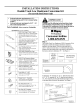
IMPORTANT INSTALLATION INSTRUCTIONS
To reduce the risk of severe injury or death:
1. READANDFOLLOWALL INSTALLATIONWARNINGS
AND INSTRUCTIONS.
2. Install garagedoor opener only on properly balanced
and lubricated garagedoor. An improperly balanced
door may not reversewhen required and could result in
severe injury or death.
3. All repairsto cables,spring assemblies and other
hardware MUSTbe made bya trained door systems
technician before installing opener.
4. Disable all locksand remove all ropesconnectedto
garage door before installing openerto avoid
entanglement.
5. Install garagedoor opener 7 feet or more abovefloor.
6. Mount emergency releasehandle 6 feet abovefloor.
7. NEVERconnect garage door openerto power source
until instructed to do so.
8. NEVERwear watches, rings or looseclothing while
installing or servicing opener.They could be caught in
garagedoor or opener mechanisms.
9. Install wall-mounted garage door control:
• within sight of the garage door
• out of reach of children at minimum height of 5 feet
• awayfrom all moving parts of the door.
10. Placeentrapment warning labelon wall nextto garage
door control.
11. Placemanualrelease/safetyreversetest label in plain
view on inside of garage door.
12. Uponcompletion of installation, test safety reversal
system. Door MUST reverseon contact with a one-
inch high object (or a 2x4 laid flat) onthe floor.
11

INSTALLATION STEP 1
Determine the Header Bracket
Location
To prevent possible SERIOUSINJURYor DEATH:
• HeaderbracketMUSTbe RIGIDLYfastenedto
structural support on headerwall or ceiling, otherwise
garagedoor might not reversewhen required. DONOT
install header bracketover drywall.
• Concreteanchors MUST be usedif mounting header
bracket or 2x4 into masonry.
• NEVERtry to loosen, move or adjust garagedoor,
springs, cables,pulleys, brackets, or their hardware, all
of which are under EXTREMEtension.
• ALWAYScall a trained door systems technician if
garagedoor binds, sticks, or is out of balance.An
unbalancedgarage door might not reverse when
required.
Vertical
Centerline
Finished
Ceiling
Structural
Supports
Installation procedures vary according to garage door
types. Follow the instructions which apply to your
door.
SECTIONAL DOOR
AND ONE-PIECE DOOR WITH TRACK
1. Close the door and mark the inside vertical
centerline of the garage door.
2. Extend the line onto the header wall above the
door.
You can fasten the header bracket within 4 feet
of the left or right of the door center only if a
torsion spring or center bearing plate is in the
way; or you can attach it to the ceiling (see
page 14) when clearance is minimal. (It may be
mounted on the wall upside down if necessary,
to gain approximately 1/2".)
If you need to install the header bracket on a 2x4
(on wall or ceiling), use lag screws (not provided)
to securely fasten the 2x4 to structural supports as
shown here and on page 13.
3. Open your door to the highest point of travel as
shown. Draw an intersecting horizontal line on the
header wall 3" above the high point. This height
will provide travel clearance for the top edge of the
door.
NOTE: Door clearance brackets are available for
sectional doors when headroom clearance is less
than 2". See accessory page 39.
Proceed to Step 2, page 14.
12
Ceiling
Header Wall
,, 3" Track
, I
Highest Point
of Travel
Door
Sectional door
with curved
track
One-piece
door with
horizontal
track
Heartier Wall
3" Track
t_Highest Point

ONE-PIECE DOOR WITHOUT TRACK
1. Close the door and mark the inside vertical
centerline of your garage door. Extend the line
onto the header wall above door, as shown.
If headroom clearance is minimal, you can install
the header bracket on the ceiling. See page 14.
If you need to install the header bracket on a 2x4
(on wall or ceiling), use lag screws (not provided)
to securely fasten the 2x4 to structural supports
as shown.
2. Open your door to the highest point of travel as
shown. Measure the distance from the top of the
door to the floor. Subtract the actual height of the
door. Add 8" to the remainder. (See Example).
3. Close the door and draw an intersecting horizontal
line on the header wall at the determined height.
NOTE: If the total number of inches exceeds the
height available in your garage, use the maximum
height possible, or refer to page 14 for ceiling
installation.
Header Wall
Unfinished
Ceiling
Vertical
Centerline
2x4
OPTIONAL
CEILING MOUNT
FOR
HEADER BRACKET
EXAMPLE
Distance from top of door
(at highest point of travel) to floor ...................... 92"
Actual height of door .......................................... -88"
Remainder .......................................................... 4"
Add ..................................................................... +8"
Bracket height on header wall ............................. 12"
(Measure UP from top of CLOSED door.)
Proceed to Step 2, page 14.
Door 1
Jamb
Hardware
Header Wall
Highest Point
of Travel
Floor
One-piece door without track:
jamb hardware
Door
Highest Point
of Travel
Header Wall I
Ii
Ii
I I
121
Floor
13
One-piece door without track:
pivot hardware

INSTALLATION STEP 2
Install the Header Bracket
You can attach the header bracket either to the wall
above the garage door, or to the ceiling. Follow the
instructions which will work best for your particular
requirements. Do not install the header bracket
over drywall. If installing into masonry, use
concrete anchors (not provided).
WALL HEADER BRACKET INSTALLATION
• Center the bracket on the vertical centerline with
the bottom edge of the bracket on the horizontal
line as shown (with the arrow pointing toward the
ceiling).
• Mark the vertical set of bracket holes (do not use
the holes designated for ceiling mount). Drill 3/16"
pilot holes and fasten the bracket securely to a
structural support with the hardware provided.
HARDWARE SHOWN ACTUAL SIZE
Lag Screw
5/16"-9 x 1-5/8"
Wall Mounting Holes
Optional
Wall Mounting Holes
Highest Point of
/
Garage Door Travel ,_1
f I
The nail hole is for
positioning only.
must use lag screws
to mount the header bracket.
t Vertical
...... Center ne
L r w
fF ag Sc e s
_. 5/16"x9x1-5/8"
_/)_2L Door Spring
I _ Garage
,,_ - Door-
I_ Vertical
I I Centerline
i
CEILING HEADER BRACKET INSTALLATION
• Extend the vertical centerline onto the ceiling as
shown.
• Center the bracket on the vertical mark, no more
than 6" from the wall. Make sure the arrow is
pointingtoward the wall. The bracket can be
mounted flush against the ceiling when clearance
is minimal.
• Mark the side holes. Drill 3/16" pilot holes and
fasten bracket securely to a structural support with
the hardware provided.
Ceiling Mounting Holes
/%
/
Tohset?oan=lmh;Ioer_yf° r (_ _ __ (_
8"
Door
Lag Screws
5/16"x9x1-5/8"
Header Wall
14

Header Wall
Rail Bracket
INSTALLATION STEP 3
Attach the Rail to the Header
Bracket
• Position the opener on the garage floor below the
header bracket. Use packing material as a
protective base. NOTE: If the door spring is in the
way you'll need help. Have someone hold the
opener securely on a temporary support to allow
the rail to clear the spring.
• Position the rail bracket against the header
bracket.
• Align the bracket holes and join with a clevis pin
as shown.
• Insert a ring fastener to secure.
Torsion
Spring
Ring Fastener
Header Bracket
Garage
Door
Clevis Pin
5/16"x2-3/4"
Rail
Bracket
Rail
Foam Packaging --
Opener Carton or
Temporary
Support
HARDWARE SHOWN ACTUAL SIZE
o]
Clevis Pin
5/16"x2-3/4"
O
Ring Fastener
15

INSTALLATION STEP 4
Install the Safety Reversing Sensor
The safety reversing sensor must be connected
and aligned correctly before the garage door
opener will move in the down direction.
IMPORTANT INFORMATION ABOUT
THE SAFETY REVERSING SENSOR
When properly connected and aligned, the sensor
will detect an obstacle in the path of its electronic
beam. The sending eye (with an orange indicator
light) transmits an invisible light beam to the
receiving eye (with a green indicator light). If an
obstruction breaks the light beam while the door is
closing, the door will stop and reverse to full open
position, and the opener lights willflash 10 times.
The units must be installed inside the garage so that
the sending and receiving eyes face each other
across the door, no more than 6" above the floor.
Either can be installed on the left or right of the door
as long as the sun never shines directly into the
receiving eye lens.
The mounting brackets are designed to clip onto the
track of sectional garage doors without additional
hardware.
• Besure power is not connectedto the garagedoor
opener BEFOREinstalling the safety reversing sensor.
• To prevent SERIOUSINJURYor DEATHfrom a closing
garage door:
- Correctlyconnect and align the safety reversing
sensor.This required safety deviceMUST NOTbe
disabled.
- Install the safety reversing sensor so beam is NO
HIGHERthan 6"above garagefloor.
If it is necessary to mount the units on the wall, the
brackets must be securely fastened to a solid
surface such as the wall framing. Extension brackets
(see accessories) are available if needed. If
installing in masonry construction, add a piece of
wood at each location to avoid drilling extra holes in
masonry if repositioning is necessary.
The invisible light beam path must be unobstructed.
No part of the garage door (or door tracks, springs,
hinges, rollers or other hardware) may interrupt the
beam while the door is closing.
Sensor Beam Invisible Light Beam
6" max. Protection Area
above floor
Sensor Beam
6" max.
above floor
Facing the door from inside the garage
16

INSTALLING THE BRACKETS
Be sure power to the opener is disconnected.
Install and align the brackets so the sensors will face
each other across the garage door, with the beam no
higher than 6" above the floor. They may be installed
in one of three ways, as follows.
Garage door track installation (preferred):
• Slip the curved arms over the rounded edge of
each door track, with the curved arms facing the
door. Snap into place against the side of the track.
It should lie flush, with the lip hugging the back
edge of the track, as shown in Figure 1.
If your door track will not support the bracket
securely, wall installation is recommended.
Wall installation:
• Place the bracket against the wall with curved arms
facing the door. Be sure there is enough clearance
for the sensor beam to be unobstructed.
• If additional depth is needed, an extension bracket
(see Accessories) or wood blocks can be used.
• Use bracket mounting holes as a template to locate
and drill (2) 3/16" diameter pilot holes on the wall at
each side of the door, no higher than 6" above the
floor.
• Attach brackets to wall with lag screws
(not provided).
• If using extension brackets or wood blocks, adjust
right and left assemblies to the same distance out
from the mounting surface. Make sure all door
hardware obstructions are cleared.
Floor installation:
• Use wood blocks or extension brackets (see
Accessories) to elevate sensor brackets so the
lenses will be no higher than 6" above the floor.
• Carefully measure and place right and left
assemblies at the same distance out from the wall.
Be sure all door hardware obstructions are cleared.
• Fasten to the floor with concrete anchors as shown.
Figure 1
DOOR TRACK MOUNT (RIGHT SIDE)
Door
Track
'\
Sensor
acket
Indicator
light
Figure 2
(Provided with
Extension z-.i_""
Bracket)
WALL MOUNT (RIGHT SIDE)
xten oo
Bracket
(See Accessories)
I /Prov dedw th
Sensor
I Indicator
Lens light
Figure 3
Lens
Sensor
Bracket
(Provided
Extension
Bracket)
FLOOR MOUNT (RIGHT SIDE)
Indicator
light
(Provided with
Extension Bracket)
Attach with
concrete anchors
(not provided)
Extension
Bracket
(See Accessories)
17

MOUNTING AND WIRING THE SAFETY SENSORS
• Slide a 1/4"-20xl/2" carriage bolt head into the slot
on each sensor. Use wing nuts to fasten sensors
to brackets, with lenses pointing toward each other
across the door. Be sure the lens is not obstructed
by a bracket extension. See Figure 4.
• Finger tighten the wing nuts.
Recommended Wire Routing
1. Using insulated staples, run the wires from both
sensors to the rail at the door header
(see Figure 5).
2. Cross and twist the two wires where they meet
the rail (see inset A). Run the wires inside the
channels at the top of the rail, along each side,
to the motor unit. Do not use the lower (trolley)
channels. Use a screwdriver tip to tuck the wires
snugly into the channels.
NOTE: If your access door is near the garage
door, you may choose to install the door control at
this time and run the door control wire along the
rail with the sensor wires. Use one rail channel for
the door control wire and the other channel for
both sensor wires. If you choose this option, follow
instructions 1-3 on page 21 now.
3. Pull wires taut across the top of the chassis and
insert into the opening above the terminal block
(see inset B). You will complete the wiring in
Installation Step 7.
Figure 5
Figure 4
Carriage bolt _"_)
1/4"-20xl/2"
HARDWARE SHOWN ACTUAL SIZE
Carriage Bolt Wing Nut
1/4"-20xl/2" 1/4"-20
Staples
Sensor
Wire
Twist
Wires
Header
-- Wall --
Sensor
Wire
Header
Bracket
1. Run wires from sensors to end of rail
at the door header. Cross & twist here to
help contain wires in channels on top of rail.
B
/" _. _ 2. Run wires along channels
#1" ./,,_,-_4---'-"_ to motor unit. Use screwdrive blade
/ _A t° tuck snugly int° channels"
oo °
3.Pu.wirestautacrosstopof
o _ _ __ _"_ and !nsert into opening above
o o o terminal block.
Sensor
Bell Wire
Invisible Light Beam
Protection Area
Rail
Channel
Sensor
18

INSTALLATION STEP 5
Position the Opener
Follow instructions which apply to your door type as
illustrated.
SECTIONAL DOOR OR ONE-PIECE DOOR WITH
TRACK
A 2x4 laid flat is convenient for setting an ideal door-
to-rail distance.
• Raise the opener onto a stepladder. You will need
help at this point if the ladder is not tall enough.
• Open the door all the way and place a 2x4 laid flat
on the top section beneath the rail.
• If the top section or panel hits the trolley when you
raise the door, pull down on the trolley release arm
to disconnect inner and outer sections. Slide the
outer trolley toward the motor unit. The trolley can
remain disconnected until Installation Step 13
is completed.
To prevent damageto garage door, rest garage door
opener rail on 2x4 placedon top section of door.
Header 2x4
Bracket
ONE-PIECE DOOR WITHOUT TRACK
• With the door fully open and parallel to the floor,
measure the distance from the floor to the top of
the door.
• Using a stepladder as a support, raise the top of
the opener to this height.
• The top of the door should be level with the top of
the motor unit. Do not position the opener more
than 3" above this point.
Header
Bracket
19

INSTALLATION STEP 6
Hang the Opener
Three representative installations are shown. Yours
may be different. Hanging brackets should be angled
(Figure 1) to provide rigid support. On finished
ceilings (Figure 2), attach a sturdy metal bracket to
structural supports before installing the opener. This
bracket and fastening hardware are not provided
(see accessories).
Existing brackets from a previous installation may be
fastened to the sides of the motor unit as in
Figures 1 and 2, or to the mounting tabs as shown in
Figure 3. Then continue with step 5 below.
1. Remove foam packaging. Measure the distance
from each side of the motor unit to the structural
support.
2. Cut both pieces of the hanging bracket to required
lengths.
3. Drill 3/16" pilot holes in the structural supports.
4. Attach one end of each bracket to a support with
5/16"-18xl -7/8" lag screws.
5. Fasten the opener to the hanging brackets with
5/16"-18x7/8" hex bolts, lock washers and nuts.
If you wish to utilize the two center mounting tabs,
you must triangulate the vertical brackets for
additional stability. See Figure 3.
6. Check to make sure the rail is centered over the
door (or in line with the header bracket if the
bracket is not centered above the door).
7. Remove the 2x4. Operate the door manually. If
the door hits the rail, raise the header bracket.
HARDWARE SHOWN ACTUAL SIZE
Lag Screw
5/16"-18xl-7/8"
O,,,,,,,,,,D@
Hex Bolt
5/16"- 18x7/8" Nut 5/16"-18 Lock Washer 5/16"
Toavoid possible SERIOUSINJURYfrom a falling
garage door opener,fasten it SECURELYto structural
supports of the garage.Concreteanchors MUSTbe used
if installing any brackets into masonry.
Figure 1 "Structural
Measure ",
Distance
Lag Screws
5/16"- 18xl -7/8"
Hex Bolts
5/16"- 18x7!8"
Lock Washers
5/16"
Nuts 5/16"-18
Preferred range of
bracket placement
Figure 2
-- FINISHED CEILING --
Hidden _ _ _ _ _ _ __ _ __ _
Support _ _ _ _
_._-_ ..... Lag Screws
Bracket _-_--_-. (Not Provided )
(Not Provided) k_k --_ Bolt
_-_- _s--_ /./_/"_ --- 5/16"-18x7/8"
_ _ -_\°_- -_ _- r/_ Lock Washer5/16"
Bolt - -- k_\ p/_ Nut 5/16"-18
5/16"-18x7/8" . _,,,.-.,_ VII_
LockWasher 5/16"-_ _ _ _
Nut 5/16 18 _
Preferred range of
bracket placement
Figure 3
Existing Brackets
Mounting Tabs
Bracket
(Provided)
20
Utilizing existing installation

INSTALLATION STEP 7
Install the Door Control
Locate door control within sight of door, at a minimum
height of 5 feet where small children cannot reach,
away from moving parts of door and door hardware.
If installing into drywall, drill 5/32" holes and use the
anchors provided. For pre-wired installations (as in
new home construction), it may be mounted to a
single gang box (Figure 2).
1. Strip 7/16" of insulation from one end of bell wire
and connect to the two screw terminals on back of
door control by color: white wire to 2 and white/red
wire to the 1.
2. Remove white cover by gently prying at slot in top
of the cover with a small flat head screwdriver.
Fasten with 6AB x 1-1/4" self-tapping screws
(drywall installation) or 6-32 x 1" machine screws
(into gang box) as follows:
• Drill and install bottom screw, allowing 1/8" to
protrude above wall surface.
• Position bottom of door control on screw head and
slide down to secure. Adjust screw for snug fit.
• Drill and install top screw with care to avoid
cracking plastic housing. Do not over tighten.
• Insert top tabs and snap on cover.
3. (Standard installation only) Run bell wire up wall
and across ceiling to motor unit. Use insulated
staples to secure wire in several places. Do not
pierce wire with a staple, creating a short or open
circuit. If your access door is near the garage door,
you may run this wire with the Safety Reversing
Sensor wires along the top of the rail. See page 18.
4. Insert all wires through the opening on top of motor
unit above the terminal block on the back panel
(Figure 3).
5. Strip 7116" of insulation from each set of wires.
Insert door control wire into quick-connect terminals
by color: white wire to white, white/red wire to red.
Separate white and white/black wires sufficiently to
connect to the opener quick-connect terminals.
Twist like colored wires together. Insert wires into
quick-connect holes: white to white and white/black
to black.
Toprevent possible SERIOUSINJURYor DEATHfrom
electrocution:
• Be sure power is not connectedBEFOREinstalling door
control.
• ConnectONLYto 24 VOLTlow voltage wires.
Toprevent possible SERIOUSINJURYor DEATHfrom a
closing garage door:
• Install door control within sight of garage door, out of
reachof children at a minimum height of 5 feet, and
awayfrom all moving parts of door.
• NEVERpermit children to operateor play with door
control push buttons or remote control transmitters.
•ActivatedoorONLYwhenit canbeseenclearly,is properly
adjusted,andthereare no obstructionsto door travel.
• ALWAYSkeepgaragedoor in sight until completely
closed. NEVERpermit anyoneto cross pathof closing
garagedoor.
Hardware Shown Actual Size
IsIclrlelwl1_,AI_I_I11111/14!,1, I ,I_
Control Console (std installation)
lllllllllllllllllllll
Screw 6-32 x ]"
Control Console (pre-wired)
Insulated
Staples
Dr,/Wall Anchors
Outside Keylock Accessory Connections
To opener quick-connect terminals: white to white;
white/red to red.
CONTROL
CONSOLE Top
Mounting Hole
Terminal
Lighted Screws
Push
Buttonr Light Bo.om
Mounting
Hole
_ Lock BACK VIEW
Figure 1 Figure 2
REMOVE & REPLACE COVER PRE-WIRED
INSTALLATION
To Replace, o Remove,
Insert Twist
Top Tabs _' Here
First
NOTE: When connecting multiple door controls to the
opener, twist same color wires together. Insert wires
into quick-connect holes: white to white and red/white
to red.
\
24 Volt \
2-Conductor
Bell Wire
6. Use tacks or staples to permanently attach
entrapment warning label to wall near door control,
and manual release/safety reverse test label in a
prominent location on inside of garage door.
NOTE: DO NOT connect the power and operate
the opener at this time. The trolley will travel to the
full open position but will not return to the
close position until the sensor beam is
connected and properly aligned.
Figure 3 Wiring to Terminal Block
Strip 7/16" of insulation from each wire. Insert wires
through opening on top of motor unit above
terminal block, then into quick-connect
terminals.
Door Control To release wire, push in tab
Connections with screwdriver tip
r__7/16_
Strip wire 7/16"
21
Red White Black

INSTALLATION STEP 8
Electrical Requirements
To avoid installation difficulties, do not run the
opener until Step 9 below.
To reduce the risk of electric shock, your garage door
opener has a grounding type plug with a third
grounding pin. This plug will only fit into a grounding
type outlet. If the plug doesn't fit into the outlet you
have, contact a qualified electrician to install the
proper outlet.
@ wo@
If permanent wiring is required by your local
code, refer to the following procedure.
To make a permanent connection through the 7/8"
hole in the top of the motor unit:
• Remove the motor unit cover screws and set the
cover aside.
• Remove the attached 3-prong cord.
• Connect the black (line) wire to the screw on the
brass terminal; the white (neutral) wire to the
screw on the silver terminal; and the ground wire
to the green ground screw. The opener must be
grounded.
• Reinstall the cover.
To prevent possible SERIOUSINJURYor DEATHfrom
electrocution or fire:
• Besure power is not connectedto the opener,and
disconnect powerto circuit BEFOREremoving cover to
establish permanent wiring connection.
• Garagedoor installation and wiring MUSTbe in
compliancewith all local electricaland building codes.
• NEVERusean extension cord, 2-wire adapter, or
changeplug in anyway to make itfit outlet. Be sure
the opener is grounded.
PERMANENT WIRING
CONNECTION
Ground Tab
Green
Ground Screw
Ground Wire
White Wire
INSTALLATION STEP 9
Complete the Safety Reversing
Sensor Installation
ALIGNING THE SAFETY SENSORS
• Plug in the opener. The indicator lights in both the
sending and receiving eyes will glow steadily if
wiring connections and alignment are correct.
The sending eye orange indicator light will glow
regardless of alignment or obstruction. If the green
indicator light in the receiving eye is off, dim, or
flickering (and the invisible light beam path is not
obstructed), alignment is required:
• Loosen the sending eye wing nut and readjust,
aiming directly at the receiving eye. Lock in place.
• Loosen the receiving eye wing nut and adjust the
sensor until it receives the sender's beam. When
the green indicator light glows steadily, tighten the
wing nut.
TROUBLESHOOTING THE SAFETY SENSORS
1. If the sending eye indicator light does not glow
steadily after installation, check for:
• Electric power to the opener.
• A short in the white or white/black wires. These
can occur at staples, or at opener connections.
• Incorrect wiring between sensors and opener.
• A broken wire.
2. If the sending eye indicator light glows steadily but
the receiving eye indicator light doesn't:
• Check alignment.
• Check for an open wire to the receiving eye.
3. If the receiving eye indicator light is dim, realign
either sensor.
NOTE: When the invisible beam path is obstructed
or misaligned while the door is closing, the door will
reverse. If the door is already open, it will not close.
The opener lights will flash 10 times. (See page 16.)
22

INSTALLATION STEP 10
Install the Lights and Lens
• Install a 100 watt maximum light bulb in each
socket. The lights will turn ON and remain lit for
approximately 4-1/2 minutes when power is
connected. Then the lights will turn OFF.
• Insert bottom lens tabs into slots on chassis. Tilt
towards chassis to engage top tabs, then drop
down gently into place. (See illustration.)
• To remove, depress both top lens tabs. Tilt lens
slightly outward and down, then pull out to clear
bulbs. Use care to avoid snapping off bottom lens
tabs.
NOTE: Use only standard light bulbs. The use of
short neck or speciality light bulbs may overheat the
endpanel or light socket.
Top Lens Tab
Lens
Bottom
Chassis Slots
, I-ll °o_'_
Top
O O O O O O , I Lens Tab
I_ T°P /_-_ ......... -_
Chassis SI°V 7-_/
__jj,-.. en,j-
- -y
Bottom Insert Bottom
Chassis Slot Lens Tabs First
INSTALLATION STEP 11
Attach the Emergency Release
Rope and Handle
• Thread one end of the rope through the hole in the
top of the red handle so "NOTICE" reads right side
up as shown. Secure with an overhand knot at
least 1" from the end of the rope to prevent
slipping.
• Thread the other end of the rope through the hole
in the release arm of the outer trolley.
• Adjust rope length so the handle is 6 feet above
the floor. Secure with an overhand knot.
NOTE: If it is necessary to cut the rope, heat seal
the cut end with a match or lighter to prevent
unraveling.
• Toprevent possible SERIOUSINJURYor DEATHfrom
a falling garage door:
- If possible, useemergencyreleasehandleto
disengagetrolley ONLYwhen garagedoor is
CLOSED.Weakor broken springs or unbalanced
door could result in an open door falling rapidly
and/or unexpectedly.
- NEVERuseemergency releasehandle unless garage
doorway is clear of persons and obstructions.
• NEVERusehandleto pull door open or closed. If rope
knot becomesuntied, you could fall.
Tro,,ey
Release Arm _--!_.L /
_'_ Overhand
EmergencyJ _/Kn°t
Release Handle
23

INSTALLATION STEP 12
Fasten Door Bracket
Follow instructions which apply to your door type
as illustrated below or on the following page.
A horizontal brace should be long enough to be
secured to 2 vertical supports. A vertical brace
should cover the height of the top panel.
The illustration shows one piece of angle iron as the
horizontal brace. For the vertical brace, 2 pieces of
angle iron are used to create a "U"-shaped support
(Figure 1). The best solution is to check with your
garage door manufacturer for an opener installation
door reinforcement kit.
NOTE: Many vertical brace installations provide for
direct attachment of the clevis pin and door arm. In
this case you will not need the door bracket; proceed
to Step 13.
SECTIONAL DOORS
• Center the door bracket on the previously marked
vertical centerline used for the header bracket
installation. Note correct UP placement, as
stamped inside the bracket. (Figure 2).
• Position the bracket on the face of the door within
the following limits:
A) The top edge of the bracket 2"-4" below the top
edge of the door.
B) The top edge of the bracket directly below any
structural support across the top of the door.
To prevent damageto garage door, reinforce insideof
door with angle iron both vertically and horizontally.
HARDWARE SHOWN ACTUAL SIZE
Nut 5/16"-18 keckwasher 5/16"
Carriage Bolt
5/16"- 18x2-1/2"
• Mark and drill 5/16" left and right fastening holes.
Secure the bracket as shown in Figure 1 if there is
vertical reinforcement.
If your installation doesn't require vertical reinforce-
ment but does need top and bottom fastening holes
for the door bracket, fasten as shown in Figure 2.
Header Bracket
Horizontal and vertical reinforcement
is needed for lightweight garage doors
(fiberglass, aluminum, steel, doors with
glass panel, etc). (Not Provided)
Vertical
Reinforcement
Vertical
Centerline
/
of Door or
einforcement Board
Carriage Bolt
5/16"-18x2-1/2"
Door
Bracket
Lock Washer
5/16"
Nut
"00.
Door Bracket
Figure 2
Figure 1
24

ONE-PIECE DOORS
Please read and comply with the warnings and
reinforcement instructions on the previous page.
They apply to one-piece doors also.
• Center the door bracket on the top of the door, in
line with the header bracket as shown. Mark either
the left and right, or the top and bottom holes.
• Drill 5/16" pilot holes and fasten the bracket with
hardware supplied.
If the door has no exposed framing, drill 3/16" pilot
holes and fasten the bracket with 5/16"x1-1/2" lag
screws (not provided) to the top of the door.
NOTE: The door bracket may be installed on the top
edge of the door if required for your installation.
(Refer to the dotted line optional placement drawing.)
Drill 3/16" pilot holes and substitute 5/16"x1-1/2" lag
screws (not provided) to fasten the bracket to the
door.
HARDWARE SHOWN ACTUAL SIZE
Nut 5/16"-18 Lockwasher 5/16"
Carriage Bolt
5/16"- 18x2-1/2"
Header Wall
Header
Bracket
2x4 Support
Optional
Placement
of Door
Bracket
--Finished Ceiling--
Door
Bracket
Vertical
Centerline of
Garage Door
Horizontal and vertical
reinforcement is needed for
lightweight garage doors
(fiberglass, aluminum, steel,
door with glass panel, etc.)
(not provided).
Door
For a door with no exposed framing,
or for the optional installation, use
5/16"x1-1/2" lag screws (not provided)
to fasten door bracket.
(_Lock
Washer
i
' 5/16"
i
i
Top of Door
Top Edge
of Door
Optional
Placement
Carriage Bolt
5/16"-18x2-1/2"
25

INSTALLATION STEP 13
Connect Door Arm to Trolley
Follow instructions which apply to your door type as
illustrated below and on the following page.
SECTIONAL DOORS ONLY
• Make sure garage door is fully closed. Pull the
emergency release handle to disconnect the outer
trolley from the inner trolley. Slide the outer trolley
back (away from the door) about 2" as shown in
Figures 1, 2 and 3.
• Figure 1:
- Fasten straight door arm section to outer trolley
with the 5/16"xl" clevis pin. Secure the
connection with a ring fastener.
- Fasten curved section to the door bracket in the
same way, using the 5/16"x1-1/4" clevis pin.
• Figure 2:
- Bring arm sections together. Find two pairs of
holes that line up and join sections. Select holes
as far apart as possible to increase door arm
rigidity.
• Figure 3, Hole alignment alternative:
- If holes in curved arm are above holes in straight
arm, disconnect straight arm. Cut about 6" from
the solid end. Reconnect to trolley with cut end
down as shown.
- Bring arm sections together.
- Find two pairs of holes that line up and join with
bolts, lock washers and nuts.
• Pull the emergency release handle toward the
opener at a 45° angle so that the trolley release
arm is horizontal. Proceed to Adjustment Step 1,
page 28. Trolley will re-engage automatically when
opener is operated.
Inner Outer
Trolley Trolley
Clevis Pin
5/16"x 1"
Emergency
Release
Handle
Figure 1
Curved DoorArm
Clevis Pin
5/16"x1-1/4"
'\.ots
r _ Door Bracket _':'--- 5/16 -18x7/8
Figure 2
1
HARDWARE SHOWN ACTUAL SIZE
Nut 5/16"-18
Clevis Pin
5/16"xl" (Trolley)
Lock Washer 5/16" Ring Fastener
Ol _ClevisPi n OlHexBol t
5/16"x1-1/4" (Door Bracket) 5/16"-18x7/8"
Figure 3
i
Bolts
5/16"-18x7/8"
Cut this end
26

ALL ONE-PIECE DOORS
1.Assemble the door arm:
• Fasten the straight and curved door arm sections
together to the longest possible length (with a 2
or 3 hole overlap).
• With the door closed, connect the straight door
arm section to the door bracket with the
5/16"x1-1/4" clevis pin.
• Secure with a ring fastener.
2. Adjustment procedures:
On one-piece doors, before connecting the door
arm to the trolley, the travel limits must be
adjusted. Limit adjustment screws are located on
the left side panel as shown on page 28. Follow
adjustment procedures below.
• Open door adjustment: decrease UP
travel limit
- Turn the UP limit adjustment screw counter-
clockwise 5 1/2 turns.
- Press the Door Control push bar. The trolley
will travel to the fully open position.
- Manually raise the door to the open position
(parallel to the floor), and lift the door arm to
the trolley. The arm should touch the trolley just
in back of the door arm connector hole. Refer
to the fully open trolley/door arm positions in
the illustration. If the arm does not extend far
enough, adjust the limit further. One full turn
equals 2" of trolley travel.
• Closed door adjustment: decrease DOWN
travel limit
- Turn the DOWN limit adjustment screw
clockwise 5 complete turns.
Door
Bracket _ _ ,_..._..-_1-- Ring
_-_-_. Fastener
_F /-\_ _ Nuts
L_XI_ __------_,,.. Lock 5/16"-18
"__ "_,,,,_ _--_,,_ Washers I
I _ _ 5/16" I ! _/!
C,ev, Str ightJ I I /I
Bolts _'e, "r ,,_._I_."_,_.,-.- _ J\ ,
5/16"-18x7/8_----_ _ "_ Curvea
Door Arm
- Press the Door Control push bar. The trolley
will travel to the fully closed position.
- Manually close the door and lift the door arm to
the trolley. The arm should touch the trolley just
ahead of the door arm connector hole. Refer to
the fully closed trolley/door arm positions in the
illustration. If the arm is behind the connector
hole, adjust the limit further. One full turn
equals 2" of trolley travel.
3. Connect the door arm to the trolley:
• Close the door and join the curved arm to the
connector hole in the trolley with the remaining
clevis pin. It may be necessary to lift the door
slightly to make the connection.
• Secure with a ring fastener.
• Run the opener through a complete travel cycle. If
the door has a slight "backward" slant in full open
position as shown in the illustration, decrease the
UP limit until the door is parallel to the floor.
NOTE: When setting the up limit on the following
page, the door should not have a "backward" slant
when fully open as illustrated below. A slight
backward slant will cause unnecessary bucking
and/or jerking operation as the door is being opened
or closed from the fully open position.
Fully Closed
Door Arm Trolley o
Connector Hole ['_]__-"
..,L,-- Emergency Release Handle
Cloosed
Fully Open
........ _ Connector Hole _Jq
...... ....... /
Ope_ Door DaCcCkwWithdSlant Door Arm
(Undesirable)
27

ADJUSTMENT STEP 1
Adjust the UP and DOWN Travel
Limits
Limit adjustment settings regulate the points at which
the door will stop when moving up or down.
To operate the opener, press the Door Control push
bar. Run the opener through a complete travel cycle.
• Does the door open and close completely?
• Does the door stay closed and not reverse
unintentionally when fully closed?
If your door passes both of these tests, no limit
adjustments are necessary unless the reversing test
fails (see Adjustment Step 3, page 30).
Adjustment procedures are outlined below. Read the
procedures carefully before proceeding to
Adjustment Step 2. Use a screwdriver to make limit
adjustments. Run the opener through a complete
travel cycle after each adjustment.
NOTE: Repeated operation of the opener during
adjustment procedures may cause the motor to
overheat and shut off. Simply wait 15 minutes and
try again.
NOTE: If anything interferes with the door's upward
travel, it will stop. If anything interferes with the
door's downward travel (including binding or
unbalanced doors), it will reverse.
Without a properly installed safety reversalsystem,
persons (particularly small children) could be
SERIOUSLYINJUREDor KILLEDby aclosing garage
door.
• Incorrect adjustment of garagedoor travel limits will
interfere with proper operation of safety reversal
system.
• If one control (forceor travel limits) is adjusted,the
other control may also needadjustment.
• After any adjustmentsare made,the safety reversal
system MUSTbetested. Door MUSTreverseon
contact with one-inch high object (or 2x4 laid flat) on
floor.
To prevent damageto vehicles, be sure fully open door
provides adequateclearance.
HOW AND WHEN TO ADJUST THE LIMITS
• If the door does not open completely but opens
at least five feet:
Increase up travel. Turn the UP limit adjustment
screw clockwise. One turn equals 2" of travel.
• If door does not open at least 5 feet:
Adjust the UP (open) force as explained in
Adjustment Step 2.
• ff the door does not close completely:
Increase down travel. Turn the down limit
adjustment screw counterclockwise. One turn
equals 2" of travel.
If door still won't close completely, try lengthening
the door arm (page 26) and decreasing the down
limit.
If the opener reverses in fully closed position:
Decrease down travel. Turn the down limit
adjustment screw clockwise. One turn equals 2"
of travel.
Travel Limit
Adjustment
Screws
Left Side Panel
i_+_djust UP Travel
+'_ Adjust DOWN Travel
If the door reverses when closing and there is
no visible interference to travel cycle:
If the opener lights are flashing, the Safety
Reversing Sensors are either not installed,
misaligned, or obstructed. See Troubleshooting,
page 22.
Test the door for binding: Pull the emergency
release handle. Manually open and close the door.
If the door is binding or unbalanced, call for a
trained door systems technician. If the door is
balanced and not binding, adjust the DOWN
(close) force. See Adjustment Step 2.
28

ADJUSTMENT STEP 2
Adjust the Force
Force adjustment controls are located on the back
panel of the motor unit. Force adjustment settings
regulate the amount of power required to open and
close the door.
If the forces are set too light, door travel may be
interrupted by nuisance reversals in the down
direction and stops in the up direction. Weather
conditions can affect the door movement, so
occasional adjustment may be needed.
The maximum force adjustment range is about
3/4 of a complete turn. Do not force controls
beyond that point. Turn force adjustment controls
with a screwdriver.
NOTE: If anything interferes with the door's upward
travel, it will stop. If anything interferes with the
door's downward travel (including binding or
unbalanced doors), it will reverse.
HOW AND WHEN TO ADJUST THE FORCES
1. Test the DOWN (close) force
• Grasp the door bottom when the door is about
halfway through DOWN (close) travel. The door
should reverse. Reversal halfway through down
travel does not guarantee reversal on a one-inch
obstruction. See Adjustment Step 3, page 30.
If the door is hard to hold or doesn't reverse,
DECREASE the DOWN (close) force by turning
the control counterclockwise. Make small
adjustments until the door reverses normally. After
each adjustment, run the opener through a
complete cycle.
• If the door reverses during the down (close)
cycle and the opener lights aren't flashing,
INCREASE DOWN (close) force by turning the
control clockwise. Make small adjustments until the
door completes a close cycle. After each
adjustment, run the opener through a complete
travel cycle. Do not increase the force beyond the
minimum amount required to close the door.
2. Test the UP (open) force
• Grasp the door bottom when the door is about
halfway through UP (open) travel. The door should
stop. If the door is hard to hold or doesn't stop,
DECREASE UP (open) force by turning the control
counterclockwise. Make small adjustments until the
door stops easily and opens fully. After each
adjustment, run the opener through a complete
travel cycle.
• If the door doesn't open at least 5 feet,
INCREASE UP (open) force by turning the control
clockwise. Make small adjustments until door
opens completely. Readjust the UP limit if
necessary. After each adjustment, run the opener
through a complete travel cycle.
Without a properly installed safety reversal system,
persons (particularly small children) could be
SERIOUSLYINJUREDor KILLEDby a closing garage
door.
•Too much force on garage door will interfere with
proper operation of safety reversalsystem.
• NEVERincreaseforce beyondminimum amount
required to close garage door.
• NEVERuseforce adjustmentsto compensatefor a
binding or sticking garage door.
• If one control (force or travel limits) is adjusted,the
other control may also needadjustment.
• After any adjustments are made,the safety reversal
system MUST betested. Door MUSTreverseon
contact with one-inch high object (or 2x4 laid flat) on
floor.
Back Panel
Force Adjustment
Controls
-- DOWN
Force
29

ADJUSTMENT STEP 3
Test the Safety Reversal System
TEST
• With the door fully open, place a one-inch board
(or a 2x4 laid flat) on the floor, centered under the
garage door.
• Operate the door in the down direction. The door
must reverse on striking the obstruction.
ADJUST
• If the door stops on the obstruction, it is not
traveling far enough in the down direction.
Increase the DOWN limit by turning the DOWN
limit adjustment screw counterclockwise 1/4 turn.
NOTE: On a sectional door, make sure limit
adjustments do not force the door arm beyond a
straight up and down position. See the illustration
on page 26.
• Repeat the test.
• When the door reverses on the one-inch board,
remove the obstruction and run the opener
through 3 or 4 complete travel cycles to test
adjustment.
IMPORTANT SAFETY CHECK:
Repeat Adjustment Steps 1,2 and 3 after:
• Each adjustment of door arm length, limits, or
force controls.
• Any repair to or adjustment of the garage door
(including springs and hardware).
• Any repair to or buckling of the garage floor.
• Any repair to or adjustment of the opener.
Without a properly installed safety reversal system,
persons (particularly small children) could be
SERIOUSLYINJUREDor KILLEDby a closing garage
door.
• Safetyreversal system MUSTbe tested every month.
• If one control (force or travel limits) is adjusted,the
other control may also needadjustment.
• After ANYadjustments are made,the safety reversal
system MUSTbe tested. Door MUSTreverseon
contact with one-inch high object (or 2x4 laid flat) on
the floor.
One-inch board (or a 2x4 laid flat)
ADJUSTMENT STEP 4
Test the Protector System s
• Press the remote control push button to open the
door.
• Place the opener carton in the path of the door.
• Press the remote control push button to close the
door. The door will not move more than an inch,
and the door control will blink 10 times.
The garage door opener will not close from a remote
if the indicator light in either sensor is off (alerting
you to the fact that the sensor is misaligned or
obstructed).
If the opener closes the door when the safety
reversing sensor is obstructed (and the sensors
are no more than 6" above the floor), call for a
trained door systems technician.
Without a properly installed safety reversing sensor,
persons (particularly small children) could be
SERIOUSLYINJUREDor KILLED bya closing garage
door.
Safety Reversing Sensor
30

OPERATION
IMPORTANT SAFETY INSTRUCTIONS
To reduce the risk of severe injury or death:
1. READAND FOLLOWALL WARNINGSAND
INSTRUCTIONS.
2. ALWAYSkeepremote controls out of reachof children.
NEVERpermit children to operateor playwith garage
door control push buttons or remote controls.
3. ONLYactivate garagedoor when it can beseen clearly,it
is properly adjusted, and there are no obstructions to
door travel.
4. ALWAYSkeepgarage door in sight until completely
closed. NOONESHOULDCROSSTHE PATHOFTHE
MOVINGDOOR.
5. If possible, useemergency releasehandleto disengage
trolley ONLYwhen garage door is CLOSED.Weak or
brokensprings or unbalanceddoor could result in an
open door falling rapidly and/or unexpectedly.
6. NEVERuseemergency releasehandle unless garage
doorway is clearof persons and obstructions.
7. NEVERuse handleto pull garage door open or closed. If
rope knot becomesuntied, you could fall.
8. If one control (force or travel limits) is adjusted,the
other control may also needadjustment.
9. After any adjustments are made, the safety reversal
system MUSTbe tested.
10. Safety reversalsystem MUST betested every month.
Garagedoor MUSTreverseon contact with one-inch
high object (or a 2x4 laid flat) onthe floor.
11. ALWAYSKEEPGARAGEDOORPROPERLYBALANCED
(see page3). An improperly balanceddoor maynot
reverse when required and could result in severe injury
or death.
12. All repairsto cables,spring assemblies and other
hardware, all of which are under EXTREMEtension,
MUST be madeby a trained door systems technician.
13. ALWAYSdisconnect electric powerto garage door
opener before making any repairs or removing covers.
14.SAVETHESEINSTRUCTIONS.
Using Your Garage Door Opener
Your Security+ opener and hand-held remote control
have been factory-set to a matching code which
changes with each use, randomly accessing over
100 billion new codes. Your opener will operate with
up to eight Security+ remote controls and one
Security+ Keyless Entry System. If you purchase a
new remote, or if you wish to deactivate any remote,
follow the instructions in the Programming section.
Activate your opener with any of the following:
• The hand-held Remote Controh Hold the large
push button down until the door starts to move.
• The wall-mounted Door Controh Hold the push
button or bar down until the door starts to move.
• The Keyless Entry (See Accessories) If provided
with your garage door opener, it must be
programmed before use. See Programming.
When the opener is activated (with the safety
reversing sensor correctly installed and aligned)
1. If open, the door will close. If closed, it will open.
2. If closing, the door will reverse.
3. If opening, the door will stop.
4. If the door has been stopped in a partially open
position, it will close.
5. If obstructed while closing, the door will reverse. If
the obstruction interrupts the sensor beam, the
opener lights will blink for five seconds.
6. If obstructed while opening, the door will stop.
7. If fully open, the door will not close when the beam
is broken. The sensor has no effect in the opening
cycle.
If the sensor is not installed, or is misaligned, the
door won't close from a hand-held remote. However,
you can close the door with the Door Control, the
Outdoor Key Switch, or Keyless Entry, if you activate
them until down travel is complete. If you release
them too soon, the door will reverse.
The opener lights will turn on under the following
conditions: when the opener is initially plugged in;
when power is restored after interruption; when the
opener is activated.
They will turn off automatically after 4-1/2 minutes or
provide constant light when the Light feature on the
Premium Control Console is activated. Bulb size is
100 watts maximum.
Security÷ Light Feature: Lights will also turn on
when someone walks through the open garage door.
With a Premium Control Console, this feature may be
turned off as follows: With the opener lights off, press
and hold the light button for 10 seconds, until the
light goes on, then off again. To restore this feature,
start with the opener lights on, then press and hold
the light button for 10 seconds until the light goes off,
then on again.
31

Using the Wall.Mounted
Door Control
To Open the Door Manually
THE PREMIUM CONTROL CONSOLE
Press the lighted push
button to open or close the
door. Press again to
reverse the door during the
closing cycle or to stop the
door while it's opening.
Light feature
LIGHTED
-- PUSH BUTTON
-- LIGHT BUTTON
LOCK BUTTON
Press the Light button to turn the opener light on or
off. It will not control the opener lights when the door
is in motion. If you turn it on and then activate the
opener, the light will remain on for 4-1/2 minutes.
Press again to turn it off sooner. The 4-1/2 minute
interval can be changed to 1-1/2, 2-1/2, or 3-1/2
minutes as follows: Press and hold the Lock button
until the light blinks (about 10 seconds). A single blink
indicates that the timer is reset to 1-1/2 minutes.
Repeat the procedure and the light will blink twice,
resetting the timer to 2-1/2 minutes. Repeat again for
a 3-1/2 minute interval, etc., up to a maximum of four
blinks and 4-1/2 minutes.
Lock feature
Designed to prevent operation of the door from hand-
held remote controls. However, the door will open
and close from the Door Control, the Outdoor Key
Switch and the Keyless Entry Accessories.
To activate, press and hold the Lock button for two
seconds. The push button light will flash as long as
the Lock feature is on.
To turn off, press and hold the Lock button again for
two seconds.The push button light will stop flashing.
The Lock feature will also turn off whenever the
Learn button on the motor unit panel is activated.
Additional feature when used with the 3-function
hand-held remote
To control the opener lights:
In addition to operating the door, you
may program the remote to operate
the lights.
1. With the door closed, press and hold a small
remote button that you want to control the light.
2. Press and hold the Light button on the Premium
Control Console.
3. While holding the Light button, press and hold the
Lock button on the door control.
4. After the opener lights flash, release all buttons.
• To prevent possible SERIOUSINJURYor DEATHfrom
a falling garage door:
- If possible, use emergencyreleasehandleto
disengagetrolley ONLYwhen garage door is
CLOSED.Weak or brokensprings or unbalanced
door could result in an open door falling rapidly
and/or unexpectedly.
- NEVERuseemergencyreleasehandle unless garage
doorway is clear of personsand obstructions.
• NEVERuse handleto pull door open or closed. If rope
knot becomesuntied, you could fall.
DISCONNECT THE TROLLEY:
The door should be fully closed
if possible. Pull down on the
emergency release handle (so
that the trolley release arm
snaps into a vertical position)
and lift the door manually. The
lockout feature prevents the
trolley from reconnecting
I1_| Trolley
_/X Release Arm
I _r (in Manual
_l, _ Disconnect
Position)
Lockout position
automatically, and the door can (Manual disconnect)
be raised and lowered manually
as often as necessary.
TO RE-CONNECT THE
TROLLEY:
Pull the emergency release
handle toward the opener at a
45 ° degree angle so that the
trolley release arm is horizontal.
The trolley will reconnect on the
next UP or DOWN operation,
either manually or by using the
door control or remote.
o o
_ Trolley© ©
II •
_[.._._'_ R_eYe
Emergency _ Arm
Release _ _
Handle _ _
(Pull at 45° angle)
To reconnect
32

Care of Your Opener THE REMOTE CONTROL BATTERY
LIMIT AND FORCE ADJUSTMENTS
Weather conditions may cause some
minor changes in
door operation
requiring some
re-adjustments,
particularly during
the first year of
operation.
Pages 28 and 29
FORCE CONTROLS LIMIT CONTROLS
refer to the limit and force adjustments. Only a
screwdriver is required. Follow the instructions
carefully.
Repeat the safety reverse test (page 30) after any
adjustment of limits or force.
MAINTENANCE SCHEDULE
Once a Month
• Manually operate door. If it is unbalanced or
binding, call for professional garage door service.
• Check to be sure door opens & closes fully. Adjust
limits and/or force if necessary. (See pages 28
and 29.)
• Repeat the safety reverse test. Make any
necessary adjustments. (See page 30.)
Once a Year
• Oil door rollers, bearings and hinges. The opener
does not require additional lubrication. Do not
grease the door tracks.
To prevent possible SERIOUSINJURYor DEATH:
• NEVERallow small children near batteries.
• If battery is swallowed, immediately notify doctor.
The lithium battery should
produce power for up to
5 years. To replace battery,
use the visor clip or
screwdriver blade to pry open
the case as shown. ("Open"
location is stamped on back of
remote control case.) Insert
battery positive side down.
Dispose of old battery properly.
3-FUNCTION
Open this end
first to avoid/_ _ _J
cracking ,_ _-_-J_ _/
hous_
NOTICE:To comply with FCCrules, adjustment or modifications of this receiver and/or
transmitter are prohibited, exceptfor changingthe code setting or replacingthe battery.
THEREARENOOTHERUSERSERVICEABLEPARTS.
Testedto Complywith FCCStandardsFORHOMEOROFFICEUSE.Operationissubjectto
the following two conditions: (1) this device may not cause harmful interference,and
(2) this device must accept any interference received, including interference that may
causeundesiredoperation.
33

Having a Problem?
1. The opener doesn't operate from either the Door
Control or the remote control'.
• Does the opener have electric power? Plug a lamp into the
outlet. If it doesn't light, check the fuse box or the circuit
breaker. (Some outlets are controlled by a wall switch.)
• Have you disabled all door locks? Review installation
instruction warnings on page 11.
• Is there a build-up of ice or snow under the door? The door
may be frozen to the ground. Remove any restriction.
• The garage door spring may be broken. Have it replaced.
• Repeated operation may have tripped the overload
protector in the motor. Wait 15 minutes and try again.
2. Opener operates from the remote, but not from the
Door Control'.
• Is the door control lit? If not, reverse the wires. If the
opener runs, check for a faulty wire connection at the door
control, a short under the staples, or a broken wire.
• Are the wiring connections correct? Review Installation
Step 7, page 21.
3. The door operates from the Door Control, but not from
the remote control'.
• Is the door push button flashing? If your model has the
Lock feature, make sure it is off.
• Program the opener to match the remote control code.
(Refer to instructions on the motor unit panel.) Repeat with
all remotes.
4. The remote control has short range:
• Change the location of the remote control in your car.
• Check to be sure the antenna on the side or back panel of
motor unit extends fully downward.
• Some installations may have shorter range due to a metal
door, foil backed insulation, or metal garage siding.
(Antenna Extender Kit 41A3504)
5. Opener noise is disturbing in living quarters of home:
• If operational noise is a problem because of proximity of the
opener to the living quarters, the Vibration Isolator Kit
41A3263 can be installed. This kit was designed to
minimize vibration to the house and is easy to install.
6. The garage door opens and closes by itself:
• Be sure that all remote control push buttons are off.
• Remove the bell wire from the door control terminals and
operate from the remote only. If this solves the problem, the
door control is faulty (replace), or there is an intermittent
short on the wire between the door control and the motor
unit.
• Clear memory and re-program all remote controls.
7. The door doesn't open completely:
• Is something obstructing the door? Is it out of balance, or
are the springs broken? Remove the obstruction or repair
the door.
• If the door is in good working order but now doesn't open
all the way, increase the up force. See Adjustment Step 2.
• If the door opens at least 5 feet, the travel limits may need
to be increased. One turn equals 2 inches of travel. See
Adjustment Step 1.
Repeat the safety reverse test after the adjustment is
complete.
8. The door stops but doesn't close completely:
• Review the travel limits adjustment procedures on page 28.
Repeat the safety reverse test after any adjustment of door
arm length, close force or down limit.
9. The door opens but won't close:
• If the opener lights blink, check the safety reversing sensor.
See Installation Step 9.
• If the opener lights don't blink and it is a new installation,
check the down force. See Adjustment Step 2. For an
existing installation, see below.
Repeat the safety reverse test after the adjustment
is complete.
10. The door reverses for no apparent reason and opener
lights don't blink:
• Is something obstructing the door? Pull the emergency
release handle. Operate the door manually. If it is
unbalanced or binding, call for professional garage door
service.
• Clear any ice or snow from the garage floor area where the
door closes.
• Review Adjustment Step 2.
• If door reverses in the fully closed position, decrease the
travel limits (Adjustment Step 1).
Repeat safety reverse test after adjustments to force or travel
limits. The need for occasional adjustment of the force and
limff settings is normal Weather conditions in particular can
affect door travel
11. The door reverses for no apparent reason and opener
lights blink for 5 seconds after reversing:
• Check the safety reversing sensor. Remove any obstruction
or align the receiving eye. See Installation Step 9.
12. The opener lights don't turn on:
• Replace the light bulbs (100 watts maximum). Use a
standard neck garage door opener bulb if regular bulb
burns out.
13. The opener lights don't turn off:
• Is the Lightfeature on? Turn it off.
14. The opener strains or maximum force is needed to
operate door:
• The door may be out of balance or the springs may be
broken. Close the door and use the emergency release
handle to disconnect the trolley. Open and close the door
manually. A properly balanced door will stay in any point of
travel while being supported entirely by its springs. If it
does not, disconnect the opener and call a professional
garage door serviceman. Do not increase the force to
operate the opener.
15. The opener motor hums briefly, then won't work:
• The garage door springs may be broken. See above.
• If the problem occurs on the first operation of the opener,
door may be locked. Disable the door lock.
Repeat the safety reverse test after the adjustment is
complete.
16. The opener won't operate due to power failure:
• Use the emergency release handle to disconnect the
trolley. The door can be opened and closed manually.
When power is restored, press the Door Control push
button and trolley will automatically reconnect (unless
trolley is in lockout position.) See page 32.
• The Emergency Key Release accessory (for use on
garages with no service door) disconnects the trolley from
outside the garage in case of power failure.
34

PROGRAMMING
Your garage door opener has already been programmed at the factory to operate with your hand-held remote
control. The door will open and close when you press the large push button.
Below are instructions for programming your opener to operate with additional Security÷ remote controls.
To Add an Additional Hand.held Remote Control
USING THE "LEARN" BUTTON USING THE PREMIUM CONTROL CONSOLE
1. Press and release the "learn"
button on the motor unit. The
learn indicator light will glow
steadily for 30 seconds.
2. Within 30 seconds, press and
hold the button on the hand-held
remote* that you wish to operate
your garage door.
3. Release the button when the
motor unit lights blink. It has
learned the code. If light bulbs are
not installed, two clicks will be
heard.
\1/
1.
2.
.
4.
Press and hold the button on the
hand-held remote* that you wish
to operate your garage door.
While holding the remote button,
press and hold the LIGHT button
on the Premium Control Console.
Continue holding both buttons
while you press the push bar on
the Premium Control Console
(all three buttons are held).
Release buttons when the motor
unit lights blink. It has learned the
code. If light bulbs are not
installed, two clicks will be heard.
To Erase All Codes From Motor
Unit Memory
To deactivate any unwanted remote,
first erase all codes:
Press and hold the "learn" button on
motor unit until the learn indicator light
goes out (approximately 6 seconds).
All previous codes are now erased. Reprogram each
remote or keyless entry you wish to use.
*Multi.Function Remotes
If provided with your garage door opener, the large
button is factory programmed to operate it. Additional
buttons on any Security÷
multi-function remote or ...._ __ __/__
mini-remote can be
programmed to operate
other Security÷ garage
door openers.
35

To Add or Change a Keyless Entry PIN
NOTE: Your new Keyless Entry must be programmed to operate your garage door opener
USING THE "LEARN" BUTTON USING THE PREMIUM CONTROL CONSOLE
1 Press and release the "learn"
button on motor unit The learn
indicator light will glow steadily for
30 seconds
2 Within 30 seconds, enter a four
digit personal identification
number (PIN) of your choice on
the keypad Then press and hold
the ENTER button
3 Release the button when the
motor unit lights blink It has
learned the code If light bulbs are
not installed, two clicks will be
heard
To change an existing, known PIN
If the existing PIN is known, it may be changed by one
person without using a ladder
1 Press the four buttons for the present PIN, then
press and hold the # button
The opener light will blink twice Release the #
button
2 Press the new 4-digit PIN you have chosen, then
press Enter
The motor unit lights will blink once when the PIN has
been learned
Test by pressing the new PIN, then press Enter The
door should move
To set a temporary PIN
You may authorize access by visitors or service people
with a temporary 4-digit PIN After a programmed
number of hours or number of accesses, this temporary
PIN expires and will no longer open the door It can be
used to close the door even after it has expired To set
a temporary PIN:
1 Press the four buttons for your personal entry PIN
(not the last temporary PIN), then press and hold the
=_button
The opener light will blink three times Release the
button
36
NOTE: This method requires two people if the Keyless
Entry is already mounted outside the garage.
1.
2.
.
Enter a four digit personal
identification number (PIN) of your
choice on the keypad Then press
and hold ENTER
While holding the ENTER button,
press and hold the LIGHT button
on the Premium Control Console
Continue holding the ENTER and
LIGHT buttons while you press
the push bar on the Premium
Control Console (all three buttons
are held)
4. Release buttons when the motor
unit lights blink It has learned the
code If light bulbs are not
installed, two clicks will be heard
2 Press the temporary 4-digit PIN you have chosen,
then press Enter
The opener light will blink four times
3 To set the number of hours this temporary PIN will
work, press the number of hours (up to 255), then
press 8
OR
3 To set the number of times this temporary PIN will
work, press the number of times (up to 255), then
press #
The opener light will blink once when the temporary PIN
has been learned
Test by pressing the four buttons for the temporary PIN,
then press Enter The door should move If the
temporary PIN was set to a certain number of openings,
remember that the test has used up one openingTo
clear the temporary password, repeat steps 1-3, setting
the number of hours or times to 0 in step 3

REPAIR PARTS
Rail Assembly Parts
_9
10
7
3
5
6
KEY PART
NO. NO. DESCRIPTION
1 41A4796-3 Hardware bag
2 41A4795-3 Hardware bag (includes
sprocket coupling)
3 12B569-1 Left rail bracket
4 12B569-2 Right rail bracket
5 1C4827-5 Screw drive rail assembly
6 12B560-1 Rail support braces (4)
7 81C168 Rack
8 41C4677 Complete trolley assembly
9 25C20 Sprocket coupling
10 41A4836 Drive sprocket kit
Installation Parts
KEY
NO.
1
2
3
4
5
6
7
8
9
10
11
12
14
PART
NO. DESCRIPTION
41A4884
29B137
41A5076
10A20
41A2828
217A238
41A5047
41A4353
41A5034
178B35
178B34
12B350
41A5266-1
41A4675-5
114A2630
Premium control console
Visor clip
3-function remote control case
(no circuit board)
3V 2032 Lithium battery (1 required)
Emergency release rope & handle assy.
2-Conductor bell wire: white &
white/red
Door bracket w/clevis pin & fastener
Header bracket w/clevis pin & fastener
Safety sensor kit: receiving and
sending eyes with 3' 2-conductor bell
wire attached
Curved door arm section
Straight door arm section
Hanging brackets
Safety sensor bracket
NOT SHOWN
Installation hardware bag (see page 7)
Owner's manual
37

Motor Unit Assembly Parts
2
17
(Down)
Brown Contact LIMIT SWITCH ASSY.
Wire
/_ _vf!iJJ///////J/////_
• _. =_Dl_ ..... _' Wire
Contact Contact Wire
12
6
8b\
13
16
KEY PART KEY PART
NO. NO. DESCRIPTION NO. NO. DESCRIPTION
1 31 D477 Drive shaft cover 8f 41A5394 Assy. bracket motor mount
2 41B4245 Line cord 8g 81B170-1 Shaft limit worm
3 30B363 Capacitor- 1/2 HP 9 41C4672 Screw drive RPM kit
4 12A373 Capacitor bracket 10 41A4837-1 Worm gear and retainer
5 41A3150 Terminal block w/screws 11 41C5417 Low voltage wire harness
6 41 D4671 Limit switch assembly 11a 41C5416 High voltage wire harness
7 12D630 Bracket: light socket, limit switch 12 41A5389B Receiver logic board assy.
8 41A5388 Motor drive assy complete with: 13 41A5490-12 Cover
8a 144B41 22T Pulley 14 41C22-1 Drive coupling hub
8b 144B42 28T Pulley 15 175C147 Light socket
8c 20B17 Drive belt 16 108D60 Light lens
8d 158A69 Retainer rings
8e 41C556 Isolator bracket spacers 17 41A5387 Chassis with rail bracket
18 12B654 Motor support bracket
38

ACCESSORIES
139.53702
Emergency Key Release:
Required for a garage with NO
access door. Enables homeowner
to open garage door manually from
outside by disengaging trolley.
139.53681
SECURITY+ 3-Function Remote
Control:
Includes visor clip.
139.53703
139.53404
139.53589
139.53709
41A5281
Outdoor Key Switch:
Operates the garage door
automatically from outside when
remote control is not handy.
8 Foot Rail Extension:
To allow an 8 foot door to open
fully.
Support Brackets:
For finished ceilings or where
additional support is required, based
on garage construction. Includes
brackets and fastening hardware.
Door Clearance Brackets:
(For Sectional Doors Only)
Replaces top brackets and rollerson
door to reduce height of door travel.
For use when installingopener in
garage with low headroom clearance.
Extension Brackets:
(Available only through Sears
Parts & Service)
(Optional) For safety sensor
installation onto the wall or floor.
139.53680
139.53684
139.53687
139.53686
SECURITY+ Compact
3-Function Remote Control:
With loop for attaching key ring.
SECURITY+ Keyless Entry:
Enables homeowner to operate
garage door opener from outside by
entering a password. Also can add
a temporary password for visitors or
service persons.
Premium Control Console:
Provides a lock feature to prevent
operation of garage door from
portable remotes. A light feature
controls the opener lights. Can be
used to program the opener to
accept additional remotes.
Plug-In Light Control:
Enables homeowner to turn on a
lamp, television or other appliance
from car, bedside, or anywhere in
the home with a remote.
WARRANTY
SEARS WARRANTY
FULL 90-DAY WARRANTY ON GARAGE DOOR OPENER
For 90 days from the date of purchase, Sears will repair this Garage Door Opener, free of charge, if defective in material or workmanship.
LIMITED WARRANTY
From the 91st day until 3 years from the date of purchase, Sears will furnish replacement parts for any defective parts, free of charge.
You pay for labor.
LIMITED WARRANTY ON MOTOR
I/2HP MOTOR: After 1 year and through 7 years, if the motor on this Garage Door Opener is defective, Sears will furnish a
replacement motor, free of charge. You pay for labor.
LIMITATION ON LIABILITY
SEARS WILL NOT BE LIABLE FOR LOSS OR DAMAGE TO PROPERTY OR ANY INCIDENTAL OR CONSEQUENTIAL LOSS OR
EXPENSE FROM PROPERTY DAMAGE DUE DIRECTLY OR INDIRECTLY TO THE USE OF THIS PRODUCT. Some states do not
allow the exclusion or limitation of incidental or consequential damages, so the above limitation or exclusion may not apply to you.
This warranty does not cover light bulbs or repair parts necessary because of operator abuse or negligence, including the failure to
install, adjust and operate this garage door opener according to instructions contained in the owner's manual.
WARRANTY SERVICE IS AVAILABLE BY CONTACTING THE NEAREST SEARS SERVICE CENTER IN THE UNITED STATES.
This warranty applies only while this product is in use in the United States.
This warranty gives you specific legal rights, and you may also have other rights which vary from state to state.
Sears, Roebuck and Co., Dept. 817WA, Hoffman Estates, IL 60179
39

TABLE OF CONTENTS
Introducci6n 2.7
Revisi6n de los simbolos y terminos de seguridad .............. 2
Preparaci6n de la puerta de su cochera .............................. 3
Herramientas necesarias ...................................................... 3
Planificaci6n ...................................................................... 4-5
Inventario de las cajas de cart6n .......................................... 6
Inventario de piezas .............................................................. 7
Montaje 8.11
Montaje del riel .................................................................. 8-9
Sujete el riel al motor e instale el trole ............................... 10
Coloque las mensulas del riel ............................................. 11
Instalaci6n 11.27
Instrucciones de seguridad para la instalaci6n ................... 11
Determine d6nde va a instalar
la mensula del cabezal ................................................ 12-13
Instale la mensula del cabezal ........................................... 14
Coloque el riel en la mensula del cabezal .......................... 15
Instale los sensores del sistema de
reversa de seguridad ................................................... 16-18
Coloque el abridor .............................................................. 19
Cuelgue el abridor .............................................................. 20
Instale la unidad de control de la puerta
y conecte el cableado ....................................................... 21
Requisitos para la instalaci6n electrica .............................. 22
Termine la instalaci6n de todos los sensores ..................... 22
Instale las luces y la lente ................................................... 23
Instale la manija y la cuerda de emergencia ...................... 23
Sujete la mensula de la puerta ...................................... 24-25
Conecte el brazo de la puerta al trole ........................... 26-27
Secci6n de Ajustes 28.30
Ajuste el limite del recorrido ............................................... 28
Ajuste la fuerza ................................................................... 29
Pruebe el sensor del sistema de
reversa de seguridad ........................................................ 30
Pruebe el sistema de reversa de seguridad ....................... 30
Operaci6n 31.34
Instrucciones de seguridad para la operaci6n .................... 31
C6mo usar el abridor de la puerta de su cochera ............. 31
C6mo usar la unidad de control de pared .......................... 32
C6mo abrir la puerta manualmente .................................... 32
Mantenimiento de su abridor de puerta de cochera ........... 33
Si tiene algt_n problema? .................................................... 34
C6mo programar el abridor 35.36
C6mo usar un control remoto de mano .............................. 35
C6mo borrar o renovar los c6digos de seguridad .............. 35
Controles remotos de funciones mt_ltiples .......................... 35
C6mo aSadir o modificar un c6digo
de entrada sin Ilave .......................................................... 36
Accesorios 37
Garantia 37
Nbmeros de Servicio
Contra tapa
INTRODUCClON
Revisi6n de los simbolos y t_rminos
de seguridad
Este abridor de puerta de cochera ha sido diseSado para un funcionamiento seguro, siempre y cuando se instale, se pruebe,
se opere y se le de mantenimiento como se indica a Io largo de este manual, cumpliendo al pie de la letra con todas las
advertencias e instrucciones generales aqui contenidas.
Mecdnica
El_ctrica
Estas advertencias y/o simbolos de seguridad que
aparecen a Io largo de este manual le alertarAn de que
existe el riesgo de una lesiSn seria o de muerte si no se
siguen las instrucciones correspondientes. El peligro
puede ser electrico (electrocuci6n) o mecAnico. Lea las
instrucciones con mucho cuidado.
Cuando vea esta palabra y/o simbolo de seguridad a Io
largo de este manual le alertarA de que existe el riesgo de
daSar la puerta de la cochera y/o el abridor si no se siguen
las instrucciones correspondientes. Lea las instrucciones
con mucho cuidado.

Preparaci6n de la puerta de
su cochera
Antes de comenzar:
• Desarme las cerraduras.
• Retire cualquier cuerda o cable que este conectado a la
puerta.
• Haga la siguiente prueba con su puerta para verificar
que este equilibrada y que no se atore ni se pandee:
1. Levante la puerta hasta la mitad de su recorrido como
se muestra. Suelte la puerta esta deberA mantenerse
en esa posiciGn con sGIo el soporte de los resortes.
2. Suba y baje la puerta; observe si se atora con algo o
si se pandea.
Si su puerta se atora o se pandea, Ilame a un tecnico
especializado en sistemas de puertas.
Paraevitar una LESIONGRAVE0 INCLUSOLA MUERTE:
• SIEMPREIlamea un t_cnico profesional para quele d_
servicio a su puerta de cocherasi estase atora, sepandea, o
estAdesequilibrada. Unapuerta de cochera que no este bien
equilibrada puede no retroceder como se requiere.
• NUNOAintente aflojar, mover ni ajustar la puertade su
cochera, los resortes de la puerta, los cables, las poleas,las
mensulas ni la tornilleria, pues todos estos elementos est_n
bajo tensiGnEXTREMA.
• QuitarTODOSlos segurosy retirar TODASlas cuerdas
conectadasa la puertade cocheraANTESde instalary operar
el abridor de la puertadecocherapara evitarqueseenreden.
Paraevitar dafios a la puerta y al abridor:
• SIEMPREdesarme las cerraduras antes de instalar y/o de
operar el abridor.
• SOLAMENTEopereel abridor de puertade cochera con
corriente de 120V 60 Hzcon objeto de evitar su mal
funcionamiento y que el abridor sedafie.
Puerta seccional
m
Oo
"!3
0
r-
Puerta de una sola pieza
Herramientas necesarias
Durante el montaje, instalaci6n y ajuste del abridor, las
instrucciones le indicarAn usar las herramientas que
aparecen en la siguiente ilustraci6n.
Escalera
LApiz
Cintade medir
Cortadoradealambre
Taladro Brocasde3/16, 5/16,
5/32de pulgada
01_1 Uavesde tuercas
_-J 1/2,7/16 de pulgada Desarmador,destornillador
Pinzas
Sierrade mane
Martillo
Uavede tuercasde
1/2x7/16de pulgada

Planificaci6n
Identifique la altura y el tipo de su puerta de cochera.
Revise el Area de su cochera y observe si alguna de
las siguientes instalaciones corresponden a la suya.
A veces se requieren materiales adicionales, asi que tal
vez sea conveniente tener esta hoja y las ilustraciones
correspondientes a la mano cuando inicie la instalaci6n de
su abridor.
Dependiendo de sus necesidades individuales, es posible
queen algunos casos vaya a necesitar materiales o
herramientas que no se incluyen con este producto.
• Instalaci6n Paso 1 - Observe la pared o el cielo raso
justo arriba de la puerta de la cochera. La mensula del
cabezal debe de estar firmemente sujeta a los soportes
de la estructura.
• Instalaci6n Paso 6 - Si el plaf6n o cielo raso de su
cochera tiene acabados, es posible que necesite una
mensula de soporte y/o mAs pernos y tornilleria para la
instalaci6n.
• Instalaci6n Paso 4 - Dependiendo del tipo de
construcci6n de su cochera, es posible que necesite
mensulas de extensi6n o bloques de madera para
instalar los sensores.
• Instalaci6n Paso 4 - El montaje al ras del piso del
sensor que activa el sistema de reversa de seguridad
podria requerir piezas que no se incluyen.
_,Hay otra puerta que de acceso a la cochera? Si no es
asi, serA necesario contar con el sistema de Ilave de
emergencia Modelo 53702. Vea la pAgina de Accesorios.
Observe el punto donde la puerta hace contacto con el
piso. El espacio entre la base de la puerta y el piso no
debe exceder 0.625 cm (1/4 de pulgada). Si no es asi,
se corre el riesgo de que el sistema de reversa de
emergencia no funcione correctamente. Vea Ajustes,
Paso 3. Va a ser necesario reparar ya sea el piso o la
puerta.
INSTALACION CON UNA PUERTA SECCIONAL
• Si tiene una puerta de aluminio, fibra de vidrio, o con
paneles de vidrio, va a necesitar refuerzos verticales y
horizontales en la puerta. (Instalaci6n, Paso 12).
• El abridor se debe instalar arriba del centro de la puerta,
pero si existe algt_n resorte de tensi6n o placa de apoyo
en el paso de la mensula del cabezal, se puede instalar
hasta a 1.20 m (4 pies) a la derecha o a la izquierda del
centro de la puerta. Vea Instalaci6n, Pasos 1 al 12.
• Si su puerta es de mAs de 2.10 m (7 pies) de altura, vea
Extensiones de riel en la Secci6n de Accesorios.
INSTALACION CON UNA PUERTA SECCIONAL
Los refuerzosverticalesy horizontalesson
necesariosparalas puertasde cocherade
materialesmaslivianos(fibra de vidrio,acero,
aluminie,o puertascon panelesde vidrio).
Vea la pagina24, dondeencontraramasdetalles.
Pareddelantera
CIELORASOCON ACABADOS
Se requieremensula de
soporteytornillos o
sujetadores.Yeala pagina20.
Riel
Resortede extensi6n
o resortedetorsi6n
oo
Unidaddelmotor
Unidadde
controlde
la puerta,
instalada
en la pared
Sensordel sistema
de reversade seguridad
Elespacioentre la basede
la puertay el pisono debede
exceder0.625cm (1/4depulg.).
0
Pue_ade
acceso
Sensordelsistema
de reversade seguridad
ENPOSICI(_NCERRADA
Mensula
delcabezal Riel
Mensula
__, /_ delriel
eso e trole
qZ'_'-_ de la //"-T_
L_o/) puertade/ / --I
u_--_J cochera _ / I
Brazo de o
I rt /_/ L Cuerda ymanija del
a pue a _o/ I sistema deliberaci6n
__ (recto) /3/ I de emergencia
0 azo
de
I de la la puerta
J puerta (curvo)

PlanificaciGn (continba)
INSTALACION CON PUERTAS DE UNA SOLA PIEZA
• Generalmente una puerta de una sola pieza no requiere
de refuerzos adicionales. Si usted tiene una puerta de
material liviano y quiere reforzarla, consulte la
informaci6n respecto a puertas seccionales, contenida
en Instalaci6n, Paso 12.
• Dependiendo del diseSo de su puerta, tal vez necesite
piezas o sujetadores adicionales para la mensula de la
puerta (Paso 12).
Sin un sistema de reversade seguridad que funcione
debidamente,al cerrar la puertade la cocherase corre el
riesgo de que las personas (yen particular los niSos
pequeSos)sufran LESIONESGRAVESo INOLUS0 LA MUERTE.
• El espacio entre la basede la puerta de lacocheray el piso
NODEBEexceder 0.625 cm (1/4 de pulgada). De no ser asi,
el sistema de reversade seguridad no vaa funcionar
debidamente.
• El piso o la puerta de la cochera SEDEBEreparar para
eliminar este espacio.
PUERTA DE UNA SOLA PIEZA
SIN CARRIL CIELORASOCONACABADOS_k_---'J_'_ -"---_
Se requieremGnsuladesoporte '_&\ '_/_4_F
yternillos o sujetadores. \_\ _7
_ Pareddelantera S RieI Unidaddel motor
.-.U I I Unidadde controlde la puerta,
I instaladaenla pared
accoso O o,a
Sensordelsistemade
._____ Elespecioentre la basede
reversade
seguridad
la puertay el pisono debede
Sensordelsistemade exceder0.625cm (1/4depulg.).
reversade seguridad
EN POSICI(_NCERRADA
Riei
delsistemade
Brazo Brazo libereci6nde
de la de la emergencia
puerta puerta
(recto) (curvo)
1
PUERTA DE UNA PIEZA CON CARRIL I
I
El espacioentrela basede a "_ersa de seguridad I
q_ne_r _l _;of_m_a_ Japuenay el plsonoaeoeae
re_e_s'a_esdu';i&_° excederO.625cm{U4dep.g.l. I
I
Puerta
de la
cochera
EN POSICI()NCERRADA
Mensula Trole
delriel i
Mensula Brazode la _ I
puerta(curve)
delcabezal Riel
Mensula Brazode
de la la puerta
puerta (recto) Cuerday manijadel
sistemade libereci6n
de emergencia

Inventario de las cajas
Su abridor viene empacado en una caja de cart6n que
contienen el motor y las piezas que se muestran en la
siguiente ilustraci6n. Tome nota de que los accesorios van
a depender del modelo que haya comprado. Si falta alguna
pieza, revise con cuidado el material de empaque ya que
en ocasiones las piezas se atoran en el hule espuma. NO
DESTRUYA EL HULE ESPUMA (vea la pAgina 10). Toda la
tornilleria y las piezas necesarias para el montaje e
instalaci6n de su puerta se ilustran en la siguiente pAgina.
Conserve la caja y los materiales de empaque (hule
espuma) hasta que la instalaci6n y el ajuste se hayan
terminado.
SECURITY÷
Unidadde control Controlremotodetresfunciones,
Premium con clipparael visor (2)
Cople de
la polea
Lentepara la luz
SECURITY+
Entradasin Ilave
Puntalesdel
soportedelriel
(4)
Riel
Dos cablesconductores
de campana.Blancoy blanco/rojo
M_nsulasdelcabezal
ydel riel
M_nsulasparacolgar
Mensuladelcabezal
Dossensoresdelsistema de
reversade seguridad(un ojotransmisor
y un ojoreceptor)conectadosa uncable
de campanadedos conductores.
Blancoyblancoy negro
Trole
Mensuladela puerta
Dos mensulasdemontaje
parael sensordelsistemade
reversade seguridad
Secci6nrecta
del brazode
la puerta
Secci6ncurva del
brazode la puerta
Etiquetasde
seguridady
literatura

Inventario de piezas
Antes de la instalaci6n, organice todas las piezas en grupos como se muestra en la siguiente ilustraci6n.
TORNILLERJA Y PIEZAS PARA EL ARMADO
,,,,,,,,,1
Pernode Pernohexagonal Tuercade
1/4-20xl-3/4 pulg.(8) de 1/4-20x5/8pulg.(4) 1/4-20x7/16pulg.(12) Manguitodel copledela polea
TORNILLERJA Y PIEZAS PARA LA INSTALACION
Pemo de Tuercade
1/4-20xl/2 pulg.(2) mariposa(2)
1111111111
Tornillo de cabezacuadrada
de 5/16-9xl-5/8 de pulg.(2)
111111111111
Tornillodecabeza cuadrada
de 5/16-18xl-7/8 pulg.(2)
Pemode5/16-18x2-1/2pulg.(2)
Pasadorde chavetade 5/16x2-3/4 pulg.(1)
O @
Anillosujetador(3) Tuercade
5/16-18pulg(6)
@
Pemo hexagonal
de 5/16-18x7/8pulg.(4) Roldanade 5/16pulg (6)
Tornillo 6ABx1-1/4pulg. (2)
o)
I!l!ll
Taquetesparamurofalso(2)
Pasader de chaveta
de 5/16xl pulg. (1)
Manija
Grapas con
material aislante
(a0/
_ IIlllllllllllllllllll
Tornillode6/32xl pulg.(2)
Pasadorde chaveta
de 5/16x1-1/4pulg.(1)
Cuerda
oH

MONTAJE, PASO 1
Montaje del riel
No encienda ni use el abridor hasta que Ilegue al paso
de la instalaci6n correspondiente, de otra manera
corre el riesgo de complicar el proceso de instalaci6n.
1. Despues de abrir la caja del riel, p6ngala boca abajo
sobre una superficie de trabajo plana.
2. Desdoble los rieles con cuidado de no golpear la junta
de la varilla de conexi6n.
3. Voltee las secciones del riel de manera que el lado
piano este hacia abajo y el lado de la varilla este hacia
arriba.
Puntalesde
soporte
delriel
Brazo recto
de la puerta
Extenderlosextremes
de los rieleshaciafuera
la polea _
F:tiel
central
Quiteel cart6n
de protecci6n
Cajadel riel (
Quiteel cart6n --
de protecci6n
Extenderlos
extremosde los rieles
NOTA: Durante el montaje del riel nunca mueva ni jale el
asiento para el trole lejos de la varilla de conexi6n. El
asiento para el trole sale de la fabrica a 23 cm (9 pulg.)
del extremo de la varilla de conexi6n, midiendo hacia el
centro.
Si la cubierta de plastico se sale o se mueve durante el
montaje, simplemente emp#jela para colocarla en su
posici6n correcta.
Asientopara
el trole
Bolsacon las piezas
ysujetadorespara
el armadodel riel
Bolsacon las piezas
ysujetadorespara
el armado del chasis
Rielcon rueda
dentadaalextremo
Ruedadentada
delriel
Rielcentral
Asientopara
el trole
Rieldel extreme

Instalaci6n del riel (Continuaci6n)
4. Empezando en el extremo con la rueda dentada,
coloque las tres secciones del riel de manera que la
varilla de conexi6n este alineada. (Tenga cuidado de no
tocar el extremo de la varilla de conexi6n ya que tiene
orillas afiladas.)
5. Cuidadosamente deslice los pasadores en la orilla
superior de una de las secciones del riel en los orificios
de la secci6n adyacente del riel. Es muy importante
que este paso se realice sobre una superficie plana,
de otra manera corre el riesgo de que el riel no estd
correctamente alineado o que se dahen los
pasadores.
6. Coloque dos de los pemos de 1/4-20xl-3/4 de pulg. a
traves de una de los puntales de soporte, despues,
ponga el puntal con los pernos en los orificios a Io largo
de la conexi6n de las dos secciones del riel. Coloque el
otro puntal de soporte al lado opuesto del riel sobre los
pernos y ponga las tuercas de 1/4-20 de pulg. Apriete a
mano y coloque el resto de los tornillos y tuercas.
7. Manteniendo el riel recto y sobre una superficie bien
nivelada, tomar las varillas atornilladas a cada lado de la
uni6n restante y colocar en linea recta. Repetir los
pasos 5 y 6.
8. Con una Ilave de tuercas de 7/16 de pulg. y empezando
al centro, ajuste las tuercas hasta que queden bien
apretadas. No apriete en exceso.
ESTAS PIEZAS SE MUESTRAN EN SU TAMAt_IO NORMAL
Pernode Tuercas
1/4-20xl-3/4 Plug(8) de 1/4"-20
Ladohaciaelengranaje
(Extremede la polea)
Tuercas _
Puntalde
soportedelriel
Orificio de
alineamiento
Ladehacia
la puerta
Deslizarel riellaterale
haciael rielcentral
Tuercas
Pasador
del riel
Puntalde
soportedel riel
Pasador
del riel
Rielcentral
Tornillosde
1/4-20xl-3/4 de pulg.
Orificiode
alineamiento
Deslizarel riellaterale
f haciael riel central
Tomillosde
1/4-20xl-3/4 de pulg.

MONTAJE, PASO 2
Sujete el riel a la unidad del motor e
instale el trole
NOTA: Para facilitarle el montaje y la instalaci6n del motor,
vuelva a colocarlo dentro del hule espuma de protecci6n,
retire la espuma despues de concluir Instalaci6n, Paso 5
• Sobre una superficie plana, alinee el riel ya armado al
motor come se muestra en la siguiente ilustraciSn
• Deslice el cople sobre la polea del riel
• Deslice el riel a traves de la mensula del motor hasta
que el cople quede bien ajustado sobre la polea del
motor.
• Alinee los dos orificios para los tornillos del riel con los
correspondientes orificios de la mensula del motor.
Sujete con los pernos hexagonales de 1/4-20x5/8 pulg.
y sus respectivas tuercas. Aprietelos con una Ilave de
tuercas de 7/16 de pulg.
• Deslice el trole por debajo y a Io largo del riel hasta que
se atore en su lugar Asegdrese de instalarlo del lade
correcto, el braze de liberaci6n del trole debe de
estar horizontal (posici6n cerrada), con la flecha
apuntando en la direcci6n opuesta del motor.
ESTAS PIEZAS SE MUESTRAN EN SU
TAMANO NORMAL
Tuercade
Pemohexagonal 1/4"-20
Poleadel motor
Mensula
delmotor
Riel
Polea
delriel
Cople
Huleespuma
de protecci6n
Pemoshexagonales
de 1/4-20x5/8pulg
Trole
Braze deltrole
La flechaapuntadoen la direcci6n
de la puertade lacochera
10

MONTAJE, PASO 3
Coloque las m_nsulas del riel
• Alinee las mensulas con la parte trasera del riel como se
muestra.
• Atornille las mensulas con los pernos hexagonales de
1/4-20x5/8 y las tuercas respectivas. Apriete firmemente
con una Ilave de 7/16 pulg.
Ya termin6 de armar su abridor de puerta de cochera,
por favor lea las siguientes advertencias antes de
continuar a la Secci6n de instalaci6n.
Pernoshexagonales
de 1/4-20x5/8
Mensulas
delriel
Tuereasde 1/4-20pulg.
ESTAS PIEZAS SE MUESTRAN
EN SU TAMAt_IO NORMAL
Tuerca de
Pemo hexagonal 1/4"-20
F, @
INSTALACION
INSTRUCCIONES MUY IMPORTANTES PARA LA INSTALACION
Para reducir el riesgo de una lesibn grave o la muerte:
1. LEAY SIGAAL PIEDE LA LETRATODASLAS
INSTRUCCIONESPARALA INSTALACION.
2. Instale el abridor de puerta de cochera s61osi la puerta de la
cocheraest_ debidamenteequilibrada y lubricada. Si la puerta
no est_ debidamente equilibrada esposible que no retroceda
cuando asi se requiere,Io que podria ocasionar una lesi6n
grave eincluso la muerte.
3.Todas las reparacionesde los cables, resortes y otras partes
las DEBEIlevar acabo un tecnico especializadoensistemas
de puertas, antes de instalar elabridor.
4. Desarmetodos los seguros y retire todas las cuerdas
conectadasa la puertade la cochera antes de instalar el
abridor con el objeto de evitar que se enreden.
5. Instale el abridor de la puertade cochera a una distancia de
2.10 m (7 pies) del piso.
6. Monte la manijade liberaci6n de emergenciaa una distancia
de 1.80 m (6 pies)del piso.
7. NUNCAconecteel abridor dela puertade cocheraa unafuente
deenergiaelectricahastaqueasi seindique.
8. NUNCAIleve puestos relojes,anillos ni prendas muy flojas
mientras est_ instalando o dando servicio al abridor, pues
podrian atorarse en la puertade la cochera o en los
mecanismos del abridor.
9. Instaleel control de paredde la puerta de cochera:
• de manera que quedea la vista desde la puerta de
la cochera
• fuera del alcancede los nifios y a una altura minima de 5
pies
• lejos de todas las partes m6viles de la puerta.
10. Coloquela calcomaniaque adviertesobreel riesgodeenredarse
cercadelcontrolde lapuertade lacochera,enla pared.
11. Coloquelacalcomania quecontiene la prueba de reversade
seguridad y liberaci6n de emergenciaa plenavista en la
parte interior de la puertade la cochera.
12. AIconcluir la instalaci6n, pruebeel sistema de reversade
seguridad. Lapuerta DEBEretrocederal entrar en contacto
con un objeto de 2.5 cm (1 pulg.) o bien con un pedazode
madera de5 x 10 cm (2x4 pulg.) puesto sobre el piso.
11

INSTALACION, PASO 1
Determine d6nde va a instalar
la m_nsula del cabezal
Unea central
vertical
Qelo raso
Pedazode madera
de 5xl 0cm
(2x4 pulg.) Soportesde
la estrucura
Paraevitar una posible LESIONGRAVEo incluso LA MUERTE:
• Lam_nsuladelcabezalDEBEquedarRiGIDAMENTEsujetaal
soporteestructuralen lapareddelanteraoen elcieloraso,de no
serasies posiblequela puertadela cocherano retrocedacuando
serequiera.NOinstalelamensuladelcabezalen murosfalsos.
• Se DEBENusar sujetadores paraconcreto si el montaje de la
m_nsula del cabezalo del pedazode maderade 5 x 10 cm
(2 x 4 pulg.) sehaceen mamposteria.
• NUNOAtrate deaflojar,mover ni ajustar lapuertade lacochera,
los resortes,los cables,las poleas,lasm_nsulasni la tornilleria,
puestodasestaspiezasestAnbajo unatensiGnEXTREMA.
• SIEMPREIlamea un tecnico especializadoen sistemas de
puertas si la puerta de cocherase pandea,seatora o siestA
desequilibrada. Unapuerta de cocheraque no este
equilibrada puede no retrocedercuando se requiera.
El proceso de instalaciGn varia dependiendo de los
diferentes tipos de puerta de cochera. Siga las
instrucciones que correspondan a su puerta.
PUERTA SECCIONAL
Y PUERTA DE UNA SOLA PIEZA CON CARRIL
1. Cierre la puerta y marque la linea central vertical del
interior de la puerta.
2. Contint_e marcando esta linea hacia arriba hasta Ilegar a
la pared delantera, arriba de la puerta.
Es posible instalar la m_nsula del cabezal hasta a
una distancia de mdximo 1.20 m (4 pies) a cada lado
del centro de la puerta, pero dnicamente si un
resorte de torsibn o un placa central de apoyo se
encuentra en el recorrido. Tambidn cuando el
espacio es reducido, se puede instalar la mdnsula en
el cielo raso o plafbn de la cochera (vea la pdgina
14). (Asimismo, se puede instalar invertida sobre la
pared si es necesario, esto le dard aproximadamente
1.25 cm (1/2 pulg.) de espacio.)
Si necesita instalar la mensula del cabezal en un pedazo
de madera de 5x10 cm (2x4 pulg.) (ya sea en la pared o
en el techo), use tornillos de cabeza cuadrada o pijas (no
provisto) para sujetar el pedazo de madera de 5x10 cm
(2x4 pulg.) a los soportes estructurales, como se indica
aqui yen la pAgina 13.
3. Abra la puerta hasta el punto mAs alto de su recorrido
como se muestra. Marque una linea horizontal que
intersecte en la pared delantera y a 7.5 cm (3 pulg.) del
punto mAs alto del recorrido. A esta altura, el extremo
superior de la puerta tendrA suficiente espacio para su
recorrido.
NOTA: Existen tambien las mensulas de extension para
puertas seccionales que requieran mas de 5 cm (2 pulg.)
de tolerancia. Vea la SecciSn de Accesorios en la pagina 37.
Contin=Je con el Paso 2, p_gina 14.
Techo
I
Pareddelantera
7.5cm
"_ __(3_pulg.) Carril
Puntomilsalto
delr_corrido
Puerta
Puerta seccional
con carril curvo
Pareddelantera
7.5cm
I (3pulg.)
Puerta de una
sola pieza
con carril
horizontal
Puerta
Puntomas alto
delrecorrido
12

PUERTA DE UNA SOLA PIEZA SIN CARRIL
1. Cierre la puerta y marque la linea central vertical en la
parte interior de la puerta de la cochera. Extienda esta
linea hasta la pared delantera arriba de la puerta, como
se muestra en la ilustraci6n.
Si el espacio en la parte superior es muy reducido,
puede instalar la mensula del cabezal en el techo. Vea
la pAgina 14.
Si es necesario instalar la mensula del cabezal en un
pedazo de madera de 5x10 cm (2x4 pulg.) ya sea en la
pared o en el cielo raso, use los tornillos de cabeza
cuadrada o pijas (no se incluyen) para sujetar el
pedazo de madera de 5x10 cm (2x4 pulg.) a los
soportes de la estructura de la cochera,
como se muestra.
2. Abra la puerta hasta el punto mAs alto del recorrido
como se muestra. Mida la distancia entre la parte
superior de la puerta y el piso, a esto restele la
altura real de la puerta, y al resultado semele 20 cm
(8 pulg.). (Vea el ejemplo).
3. Cierre la puerta de la cochera y marque una linea
horizontal sobre la pared delantera a la altura que le
haya determinado mediante el cMculo anterior.
NOTA: Si el n#mero total de centfmetros excede la
altura disponible en su cochera, use la altura maxima
posible, o consulte la pagina 14 para la Instalaci6n en el
cielo raso o plaf6n.
EJEMPLO
Distancia entre la parte superior
de la puerta (en su punto mAs alto
de desplazamiento) y el piso ....... 2.30 m (92 pulg)
Altura real de la puerta ........... -2.20 m (-88 pulg)
Resultado ..................... -0.10 m (4 pulg)
Sume ....................... +0.20 m (+8 pulg)
Altura a la que se debe sujetar
la mensula en la pared delantera =0.30 m
(Midiendo hacia arriba desde la parte
superior de la puerta cerrada)
(=12 pulg)
ContinzJe con el Paso 2, p_gina 14.
Cielo raso sin
Pared Unea
delantera central
Pedazo
de madera
de 5xl 0 cm
(2x4 pulg.)
Uneacentral
verticalde la
puertade la
cochera
INSTALAClON
OPCIONALDE
LAMI_NSULADEL
CABEZALENEL
CIELORASO
Puerta 1
del montante
Pareddelantera
Punto masalto
delrecerddo
Piso
Puerta de una sola pieza sin carrih
tornilleria del montante
Punto masalto
delrecorrido
Pareddelantera
13
Puerta de una pieza sin carrih
tornilleria del pivote

INSTALACION, PASO 2
Instale la m_nsula del cabezal
La mensula del cabezal se puede sujetar a la pared justo
arriba de la puerta de la cochera o en el cielo raso. Siga
las instrucciones que sean las mAs adecuadas para las
necesidades de su cochera. No instale la m_nsula del
cabezal en un muro falso. Si va a sujetar la m_nsula
del cabezal a ladrillo o mamposteria, asegdrese de
utilizar sujetadores de cemento (no provisto).
INSTALACION DE LA M#NSULA DEL CABEZAL EN LA
PARED DELANTERA
• Coloque la mensula sobre la Ifnea central vertical con el
borde inferior sobre la Ifnea horizontal como se muestra
en la ilustraci6n (con la flecha de la mensula apuntando
hacia el techo).
• Marque los orificios de la mensula que van en Ifnea
vertical. Taladre los orificios con una broca de 3/16 de
pulgada y sujete la mensula al soporte de la estructura
con la tornillerfa que se indica.
ESTAS PIEZAS SE MUESTRAN
EN SU TAMAt_IO NORMAL
Tomillosde cabezacuadradao pijas
de5/16por 9xl-5/8 pulgadas
Orificios parala instalaci6nde pared
Esteorificioes solamente
paramarcarlaposici6nde
la mensula.Sedebende
utilizarlos tornillosde cabeza
cuadradao pijas para
sujetarla mensula.
Orificiosopcionales
parala instalaci6nen lapared
, Lineacentral
- vertical
Puntomasalto del
recorridodela puerta
/1de lacochera
Tornillos de cabeza
cuadradao pijasde
5/16x9x1-5/8pulgadas
Resortede la puerta
- Puertadela cochera -
Linea centralvertical
INSTALACION DE LA M#NSULA DEL CABEZAL EN EL
CIELO RASO
• Extienda la Ifnea central vertical sobre el cielo raso como
se muestra en la ilustraci6n.
• Coloque la mensula al centro de la Ifnea a no mAs de 15
cm (6 pulg.) de la pared. Cerci6rese de que la flecha de
la mensula apunte al lado opuesto de la pared. La
mensula puede ser instalada pegada al cielo raso cuando
el espacio es muy reducido.
• Marque donde va a taladrar los orificios laterales. Taladre
los orificios con una broca de 3/16 de pulgada y sujete la
mensula firmemente al soporte de la estructura con la
tornillerfa que se incluye.
Orificiosparalainstalaci6n
en el cielo raso
Esteorificio essolamentepara
marcar la posici6nde la mensula.
Se debende utilizarlostornillos
de cabezacuadradao pijaspara
sujetarla mensuladel cabezaL
.-" . _. - Cieloraso con acabados-
/ _/_ i'r"('-_" / _Mensuladel Linea centralvertical
_I, _/ ii "_. cabezal
_ Tornillosde cabeza
_ cuadradaopijasde
6x9xl-5/8pulgadas
_ Pareddelantera
14

Pareddelantera
Mensuladelcabezal
Mensula delriel
INSTALACION, PASO 3
Coloque el riel en la m_nsula
del cabezal
• Coloque el abridor sobre el piso de la cochera debajo de
la mensula del cabezal. Use el hule espuma del
empaque como base para protegerlo. NOTA: Si el
resorte de la puerta esta obstruyendo, va a necesitar
ayuda. Otra persona tendra que sostener el abridor
firmemente sobre un soporte temporal para ayudarle a
que el riel pueda librar el resorte.
• Coloque la mensula del riel junto a la mensula
del cabezal.
• Alinee los orificios de las mensulas y j6ntelas con un
pasador de chaveta como se muestra en la ilustraci6n.
• Sujetelos con un anillo sujetador.
Resorte
de
torsi6n
Pue_ade
lacochera
Riel
Anillo sujetador
\\
Mensuladelcabezal
Pasadorde _ --
chavetade
5/16x2-3/4 Mensula _
de pulg. delriel
Riel
\
Huleespumadelempaque
Cajadelabridor o soportetemporal
ESTAS PIEZAS SE MUESTRAN EN SU TAMAI_IO NORMAL
ol 0
Pasadorde chavetade
5/16por2-3/4 pulg. Anillo sujetador
15

INSTALACION, PASO 4
Instale el sensor del sistema de
reversa de seguridad
El sensor del sistema de reversa de seguridad debe
estar instalado y correctamente alineado, antes de que
el abridor de la puerta de cochera mueva la puerta
hacia abajo. Este es un dispositivo de seguridad que
no se puede desactivar.
INFORMACION IMPORTANTE CON RESPECTO
AL SENSOR DEL SISTEMA DE REVERSA
DE SEGURIDAD
Si se instala y se alinea correctamente, el sensor del
sistema de reversa de seguridad detectarA cualquier
obstAculo que se cruce en el recorrido del rayo electr6nico.
El ojo emisor (el que tiene la luz indicadora de color
anaranjado) envfa un rayo electr6nico invisible al ojo
receptor (el que tiene la luz indicadora de color verde). Si
algt_n objeto obstruyera este rayo invisible mientras la
puerta se estA cerrando, la puerta se detendrA
automAticamente, retrocederA hasta abrirse por completo,
y la luz del abridor parpadearA diez veces.
Estos sensores se deben de instalar en el interior de la
cochera de manera que el ojo emisor y el ojo receptor
esten uno frente al otro a ambos lados de la puerta y a
una distancia maxima de 15 cm (6 pulg.) del piso. Ambos
sensores se pueden instalar en cualquiera de los dos
lados de la puerta, ya sea el derecho o el izquierdo,
siempre y cuando nunca le de el sol directamente a la
lente del ojo receptor.
Las mensulas para la instalaci6n han sido disefiadas para
que se sujeten directamenta al carril de la puerta, sin la
necesidad de tornillerfa ni piezas adicionales.
• Cerci6resede quela energiael_ctrica no est_ c0nectadaal
abrid0r de la puertade la c0chera ANTESde instalar el
sensor del sistema de reversade seguridad.
• Paraevitar unaLESIONGRAVEo incluso LA MUERTEcuando
la puerta de lacochera seest_ cerrando:
- Conectey alfneecorrectamente el sensor del sistema de
reversade seguridad. Estedispositivo de seguridad es
necesarioy NOSE DEBEdesactivar.
- Instale el sensor del sistema de reversade segurida de
manera queel rayo NOESTI_a m_s de 15 cm (6 pulg.) del
piso.
Si es necesario instalar las unidades sobre la pared,
asegt_rese de que todos las mensulas esten sujetas a una
superficie s61ida, por ejemplo, uno de los soportes de la
pared. Las mensulas de extensi6n estAn disponibles, si se
necesitan (vea la Secci6n de Accesorios). Siva a instalar
los sensores sobre ladrillo o mamposterfa, use un pedazo
de madera para evitar hacer orificios innecesarios sobre el
ladrillo en caso que necesite cambiarlos de lugar.
El trayecto del rayo elecr6nico invisible debe de estar libre
de cualquier obstrucci6n. Ninguna de las partes de la
puerta (los carriles, resortes, bisagras, rodillos, u otras
piezas o tornillerfa) debe interrumpir el rayo cuando la
puerta se este cerrando.
R i n r I IL_ [ !0 [ !_ J0 ] III Rayodelsensora
Vista de la puerta desde el interior de la cochera
16

INSTALACI()N DE LAS MI_NSULAS
Asegdrese de que el abridor no estd conectado a la
corriente eldctrica.
Instale y alinee las mensulas de manera que los sensores
esten uno frente al otro en los lados opuestos de la
puerta, a una distancia maxima de 15 cm (6 pulg.) del
piso. Instale las mensulas de acuerdo con una de las tres
maneras siguientes.
InstalaciSn en el carril de la puerta de la cochera
(recomendada):
• Deslice los brazos curvos sobre la orilla redondeada de
cada uno de los carriles de la puerta, con los brazos
curvos apuntando hacia la puerta. Col6quelos en su
posici6n contra el costado del carril. Debe de quedar
parejo, con el reborde pegado a la orilla posterior del
carril, como se ilustra en la Figura 1.
Si el carril de su puerta no soporta la mensula firmemente,
se recomienda que la instale sobre la pared.
InstalaciSn en la pared:
• Coloque la mensula contra la pared con los brazos
curvos apuntando hacia la puerta. Cerci6rese de que
haya suficiente espacio para que el rayo del sensor no
se tope con ninguna obstrucci6n.
• Si es necesario tener mAs profundidad, puede usar
mensulas de extensi6n (vea Accesorios) o pedazos de
madera.
• Use los orificios de montaje de la mensula para marcar o
taladrar (2) los dos orificios de 3/16 de pulgada de
diAmetro a cada lado de la puerta a una distancia
maxima de 15 cm (6 pulg.) del piso.
• Sujete la mensula a la pared con tornillos de cabeza
cuadrada o pijas (no se incluyen).
• SiestA usando mensulas de extensi6n o pedazos de
madera por la falta de espacio, asegQrese de que las
dos unidades queden a la misma distancia de la
superficie de montaje. Asimismo, asegtJrese de que no
haya ninguna obstrucci6n.
InstalaciSn en el piso:
• Use pedazos de madera o mensulas de extensi6n (yea
Accesorios) para elevar las mensulas de los sensores de
manera que las lentes queden a una distancia maxima
de 15 cm (6 pulg.) del piso.
• Cuidadosamente mida y instale las unidades derecha y
izquierda a la misma distancia con respecto a la pared.
AsegtJrese de que no haya ninguna obstrucci6n.
• Sujete al piso las mensulas para los sensores con los
sujetadores para el piso, como se muestra en
la ilustraci6n.
Figura 1 Instalacibn en el carril de la puerta (lado
derecho)
Carrilde
la puerta
Reborde
I
c
Mensula
_ sensor
Luz
indicadora
Figura 2 Instalacibn en la pared (lado derecho)
Mensuladeextensi6n
(vea Accesorios)
(Se incluyeenel
paquetedelas
mensulasdeextensi6n)
Mensula
(Se incluyeen . sensor
el paquetede _
las mensulas Luz
de extensi6n) Lente indicedora
Figura 3 Instalacibn en el piso (lado derecho)
Lente
Mensula
del sensor
(Se incluyeenel
paquetedelas
mensulasde ...,..4
extensi6n) l
Luz
indicadora
(Se ineluyeen
s el paquetede
' _ lasmensulas
_ _ de extensi6n)
_r_ _@ use sujetadores
I'" I _J_ o pernospara
I II _ H concreto
I /U g (nose incluyen)
I
//__x_ Mensulade
[_ [_ _-_ extensi6n
__i (yea Accesorios)
17

MONTAJE Y CABLEADO DE LOS SENSORES DEL
SISTEMA DE REVERSA DE SEGURIDAD
• Deslice la cabeza de un perno de coche de 14-20xl/2
pulgada dentro de la ranura de los sensores. Use
tuercas de mariposa pare sujetar los sensores alas
mensulas, con las lentes de cada sensor frente a frente
a ambos lados de la puerta. Cerci6rese de que la
extensi6n de la mensula no obstruya las lentes. Vea la
Figure 4.
• Apriete las tuercas de mariposa a mano.
Ruta recomendada pare el cableado
1. Usando grapes con aislamiento, corra los cables de los
dos sensores haste el riel del cabezal de la puerta (vea
la Figure 5).
2. Cruce y tuerza los dos cables cuando Ilegan al riel, (vea
la Figure 5, ilustraci6n A). Ponga los cables dentro de la
canaleta de la parte superior del riel a Io largo de ambos
lados, haste que Ileguen al motor. No use la canaleta
de la parte inferior del riel ya que es para el trole.
Con la punta de un desarmador mete bien los cables
dentro de la canaleta.
NOTA: Si la puerta de acceso a su cochera se encuentra
muy cerca de la puerta de la cochera, puede optar por
instalar la unidad de control en este momento y correr el
cableado del control de la puerta a Io largo del riel, junto
con los cables de los sensores. Use una canaleta del riel
para los cables de ambos sensores, y la otra para los
cables de la unidad de control Si usted opta por hacer
esto, siga ahora las instrucciones contenidas en la pagina
21, pasos 1al 3.
3. Jale los cables de manera que queden tensos a traves
de la parte superior del chasis y pAselos por el orificio
que se encuentra sobre el bloque de terminales (vea la
Figure 5, Ilustraci6n B). TerminarA el proceso de
cableado cuando Ilegue al paso 7 de la Instalaci6n.
Figure 5
Figura 4
Pernode coche
de 1/4-20xl/2 pulg.
ESTAS PIEZAS SE MUESTRAN EN SU TAMA/_IO NORMAL
Pernode coche Tuerca de mariposa Grapes
de 1/4-20xl/2 pulg. 1/4-20
A
Cable del
sensor
Pared
delantera
Tuerza Cable del
los cables sensor
Mensuladel
cabezal
1.Corralos cablesde los sensoreshasteel
extremodel rieldel cabezaldela puerta.Cruce
ytuerza loscablesen estepuntopareque no
._=_",_salgan delacanaletadela partesuperiordel riel.
_ _ _ 2. Lleve los cables hastela unidaddelmotor
J" .,.,___..'_'_4---'-''-a trav_s dela canaleta.Con la puntade
J __ .,,_._..'_ undesarmador mete bien los cables
/ __A dentro canaleta.
r _ _l _(__ _ 3' Jale lOScablesde maneraque
f__ _ _ _._ quedentensosa trav_sde laparte
f o _/___L_ _ _ |/ superiordel chasisy pziselospot
_ _ \ _ _._"l"f elorificioque seencuentra
_ _ ._/// _j_ _1 _ J sobreel bloquede
termmales.
Cable de cam
Sensor _,readeprotecci6ndel
rayoelectr6nicoinvisible
Canaleta
del riel
Sensor
18

INSTALACION, PASO 5
Coloque el abridor
Siga las instrucciones correspondientes al tipo de puerta
de su cochera, como se muestra en la ilustraciSn.
PUERTA SECCIONAL O PUERTA DE UNA SOLA PIEZA
CON CARRIL
Un pedazo de madera de 5x10 cm (2x4 pulg.) le sera de
ayuda al determinar ta distancia ideal entre ta puerta y et
riet.
• Ponga el abridor sobre ta escalera, si ta escalera no es
to suficientemente alta, va a necesitar ayuda.
• Abra completamente la puerta y coloque et pedazo de
madera de 5x10 cm (2x4 pulg.) en la secciSn superior,
de manera que quede debajo del riet.
• Si et panel superior golpea el trole al levantar ta puerta,
jale hacia abajo et brazo de liberaciSn del trole para
desconectar las secciones interna y externa det mismo.
Destice et trole externo hacia el motor. El trole puede
permanecer desconectado hasta et final det Paso 13.
Paraevitar que la puerta de c0chera sufra dafi0s, ap0ye el riel
del abrid0r de la puerta de c0cheras0bre un pedaz0de madera
de 5x 10 cm (2 x 4 pulg.) c010cad0en la secci6n superior de
la puerta.
M_nsuladel
cabezal
Pedazode madera
de 5x10cm(2x4 pulg.)
Pue_a
Brazo de
liberaci6n --_o_
deitrole
CONTECTADO SUELTO
PUERTA DE UNA SOLA PIEZA SIN CARRIL
* Abra completamente la puerta de manera que quede
paraleta con el piso, mida ta distancia entre et piso y ta
parte superior de la puerta.
, Coloque et abridor a esta altura, utilizando una escalera
como apoyo.
, La parte superior de la puerta debe de estar alineada
con la parte superior de ta unidad det motor. No instale
el abridor a mas de 7.5 cm (3 pulg.) arriba de este
punto.
Mensuladel
cabezal
/
/
I 14
Hulees
de empaque
Partesuperior
de la puerta
19

INSTALACION, PASO 6
Cuelgue el abridor
Aquf se muestran tres ejemplos distintos para la
instalaciGn; sin embargo, es posible que su cochera no
concuerde con ninguno de etlos. Las mensulas de soporte
deben de estar en angulo (Figura 1), para que
proporcionen un soporte rfgido. En case de tener un cieto
raso (Figura 2), instale una mensula de metal resistente en
alg_n soporte de ta estrucura antes de instalar et abridor.
No se incluye esta mensula ni ta tornillerfa.
(Vea Accesorios)
Los soportes existentes de una instalaciGn previa pueden
fijarse a los lades de la unidad det motor come ilustrado en
tas Figuras 1 y 2, o alas aletas de montaje come ilustrado
en la Figura 3. A continuaciGn continue con et Paso 5
de abajo.
1. Mida ta distancia entre cada tado de ta unidad det motor
y el soporte de ta estructura.
2. Corte las dos partes de tas mensulas cotgantes a ta
medida adecuada.
3. Taladre los orificios de 3/16 de pulgada en los soportes
de la estructura.
4. Sujete un extreme de cada mensula al soporte con
tornitlos de cabeza cuadrada o pijas de
5/16 -18xl-7/8 pulgadas.
5. Sujete el abridor alas mensulas cotgantes con pernos
hexagonales de 5/16 -18x7/8 pulg., y sus tuercas y
rotdanas corespondientes.
Si desea usar las mensutas de una instalaciGn previa,
debe de cotocar una de tas mensulas cotgantes (que se
incluye en el paquete) en diagonal con respecto a tas
mensulas existentes. Vea ta Figura 3.
6. Verifique que et abridor este centrado sobre la puerta (o
alineado con la mensula det cabezal, si ta mensula no
esta centrada sobre ta puerta).
7. Quite el pedazo de madera de 5x10 cm (2x4 pulg.).
Haga funcionar la puerta manualmente. Si la puerta
gotpea et riet, suba ta mensula det cabezal.
Paraevitar la p0sibilidad de una LESIONGRAVEsi secae el
abrid0r de lapuerta de c0chera, sujetel0 FIRMEMENTEa10s
s0p0rtes estructurales de la c0chera. Se DEBENusar
sujetad0respara c0ncret0 si alguna de las mensulas seva a
instalar en mamp0sterfa.
Figura 1
Soportesde
la estructura
Midala ,
distancia
Pemoshexagonales
de 5t16-18x7t8 pulg.
tuercas de 5116pulg.
roldanasde 5f16-18 pulg.
Tornillosdecabeza
cuadradao pijasde
5t16-18xl-7t8 pulg.
Distanciarecomendada para
la colocaci6nde la m_nsula
Figura 2
-- Cielo raso con acabados--
Soportede la _ -.
estructura novisible -- -" - -" -;; ....
- -- _- - - -. - - - - Tomillosdecabeza cuadrada
. _ _ o pijasde 5/16-18xl -7t8 pulg.
aensula / _ / {:__o __ ___j-. Pernosde
(no provisto) k_k _ _5/16-18x7t8 pulg.
-___- -77J--- 1,/__ _ tuercasde 5/16 pulg.
Pernosde _ _ __'_=--- _/_ roldanasde 5t16-18pulg,
5/16-18x7t8pulg, _ _\ [/_
tuercas de , _\_,--,,_ F/,l
roldanasde _ ___
5t16-18 pulg.___
Distanciarecomendada para
la colocaci6nde la m_nsula
ESTAS PIEZAS SE MUESTRAN EN SU TAMAI_IO NORMAL
111111111111 >
TomUlode cabezacuadrada
o pijade5t16-18x1-7t8pulg.
DG @
Pemo hexagonal Tuercade
de 5/16-18x7t8pulg. 5f16-18pulg. Roldanade 5t16 pulg.
Figura3
M_nsula
(no provisto)
M_nsulasyaexistentes
PestaSasde montaje
Utilizandola instalaci6nprevia
20

INSTALACION, PASO 7
Instale la unidad de control de la puerta
Ubique el control de la puerta de manera que quede a la
vista desde la puerta y a una altura minima de 1.5 m (5 pies)
donde los niSos pequeSos no Io puedan atcanzar y lejos de
las partes mSviles de la puerta y de la torniller[a. Si se va
instalar en un muro fatso, taladre dos orificios de 0.40 cm
(5/32 de pulg.) y use los sujetadores que se incluyen. Para
una instalaciSn pre-cableada, (por ejemplo, en una casa en
construcciSn) los modelos de consola se pueden instalar en
una caja mSItiple est_ndar (Figura 2).
1. Pele 1 cm (7/16 de pulg.) det extremo del cable de campana
y con_cteto a tas terminales de tornillo correspondientes al
color del cable en la parte posterior de la puerta de la unidad
de control; blanco a 2 y blanco y rojo a 1.
2. Modelo de consola: Con un desarmador abra ta tapa por el
costado. Sujete con un tornillo autorroscante de 6AB por 1-
1/4 putgadas (instataciSn est_ndar) o con un tornilto para
metales de 6 -32 por 1 pulgadas (dentro de la caja mSItiple)
como se indica a continuaciSn:
• Perfore e instale el tornillo del fondo, permitiendo que 1/8"
sobresalga sobre la superficie de la pared.
° Coloque la parte inferior de la unidad de control de la
puerta sobre la cabeza del tornillo y deslfcelo para
sujetarlo, apriete el tornillo.
° Taladre y coloque el tornitlo de la parte superior con
precauciSn de no romper la cubierta plAstica de la unidad.
No apriete en exceso.
° Inserte las leng_etas superiores y cierre ta cubierta.
3. (lnstalaci6n est#ndar solamente) Tienda el cable del
timbre hacia arriba en la pared y atrav_s del cieloraso ala
unidad del motor. Use grampas aisladas para asegurar el
cable en varios lugares. No perfore el cable con las
grampas, Io que puede crear un cortocircuito o circuito
abierto. Si su puerta de acceso est_ cerca de la puerta del
garage, usted pued etender este cable con con el cable del
Sensor Inversor de Seguridad a Io largo del tope del riel.
Vea la p_gina 18.
4. Pase todos los cables a trav_s del orificio de la parte
superior de la unidad del motor por encima del bloque de
terminates que se encuentra en el panel posterior (Figura 3).
5 Pele 7116" de aislaciSn de cada conjunto de cables. Inserte
el cable de control de la puerta dentro de los conectores de
conexiSn r_pida por color: cable blanco a blanco, cable
blanco/rojo a rojo.
Separe los cables blancos y blanco/negro suficientemente
para conectar a los terminales de conexiSn r_pida del
abridor.Tuerza juntos los cables del mismo cotor.lnsertar
los cables dentro de los orificios de conexiSn r_pida:
blanco a blanco y blanco/negro a negro.
NOTA: AI conectar controles mEfltiples de la puerta al abre-
puertas, tuerza juntos los cables del mismo color. Inserte los
cables en los orificios de conexidn rdpida: blanco a blanco y
rojo/blanco a rojo.
6. Use tachuelas o grapas para sujetar permanentemente la
calcomania de advertencia sobre el riesgo de quedar
atrapado; esta calcomania debe estar en ta pared y cerca
del control de la puerta. La catcomania de advertencia de
la prueba de reversa de seguridad y liberaciSn manual
debe colocarse en un punto prominente del interior de la
puerta de la cochera.
NOTA: NO conecte el abridor a la energia Conexionesdel
controldelapuerta
el_ctrica ni Io haga funcionar en este
momento. El trole hard el recorrido hasta (_11ram_)
llegar ala posici6n completamente abierta,
pero no regresard ala posicidn cerrada Pelee!cableI1 ram
hasta que el rayo del sensor est#
conectado y alineado debidamente.
21
Paraevitarla posibilidadde una LESIONGRAVEo incluso LA
MUERTEporelectrocuck_n:
• ANTESde instalarel control dela puerta,cerci6resede quela
energiaeldctricano estdconectada.
• Conecteel controlSOLOacablesde bajovoltajede24VOLTIOS.
Paraevitarla posibilidadde una LESIONgraveeincluso
LAMUERTEcuandola puertadela cocheraseestAcerrando:
• Instaleelcontrol de la puertade maneraquequedeala vista
desdela puertadela cochera,fueradelalcancedelos niSosa una
alturaminima de1.5 m (5 pies),y alejadode laspartes m6viles
de lapuerta.
• NUNCApermitaquelos niSoshaganfuncionaro jueguencon los
botonesdecontrol de lapuertani con lostransmisoresdecontrol
remoto.
• Hagafuncionarla puertaSOLOsi la puedever claramente,si la
puertaest_debidamenteajustada,y si no no hayninguna
obstrucci6nensu recorrido.
• SIEMPREtengaala vistala puertadela cocherahastaqueestd
completamentecerrada.NUNCApermitaquealguienseatraviese
enel recorridodela puertade lacocheracuandoseestAcerrando.
ESTAS PIEZAS SE MUESTRAN EN SU TAMAt_IO NORMAL
';Ir/,,,10',rl:l':Lo,'ol:'0L,o
6AB por 1-1t4 pulg.(instalaci6nest_ndar)
Illllllllllllllllllll
Tomilloparela consolede controlde
6-32por 1 pulg.(instalaci6npre-cableada)
_ Grapes con
aislamiento
Sujetadoresparemuro falso
Conexiones para la unidad de control exterior
Conecte alas terminales de conexiSn rapida: el blanco al
blanco; blanco/rojo al rojo.
Orificio
UNtDADDE superiorde
CONTROL montaje
PREMIUM
Bet6ncon > Tornillos
luz terminales
Orificioinferior
de montaje
VISTAPOSTERIOR
Figura I Figura 2 INSTALAClONPRE-CABLEADA
QUITARY VOLVERA
PONERLA TAPA
Parevoivera ponerla,
primeroinserte _ Parequitar,
las leng_Jetas _ doble
24 voltiosde dos conductores
en la cajamOltiple
Figura 3 Cableado al bloque de terminales del motor
Pele 1 cm (7/16 de pulg.) Insertar los cales a
tray,s de la abertura en el tope de la unidad
del motor sobre el bloque terminal, y a
continuaci6n dentro de los terminales de
conexi6n rapida.
Paresolterel cable,
leng0etehaciedentrocon
de un destomillador
Ala sensores
unidad
Terminales
de conexi6n
Rojo Blanco Negro

INSTALACION, PASO 8
Requisitos para la instalaci6n el6ctrica
Para evitar dificultades con la instalaci6n, no encienda
ni use el abridor hasta despu_s de haber completado
el paso 9.
Para reducir el riesgo de choque electrico, su abridor para
puerta de cochera viene con una clavija de conexiGn a
tierra de tres patas. Esta clavija sGlo se puede conectar a
una toma de corriente puesta a tierra y con tres entradas.
Si la clavija no entra en la toma de corriente que usted
tiene, dirijase a un electricista profesional para que te
instale ta toma de corriente correcta.
Si la reglamentaci6n local exige que su abridor tenga
cableado permanente, siga los siguientes pasos.
Para conectar el abridor a la corriente electrica de forma
permanente a traves del orificio de 2.19 cm (7/8 pulg.)
tocalizado en la parte superior del motor:
• Quite los tornillos de ta tapa det abridor y deje ta
cubierta a un lado.
• Quite el cable de tres entradas.
• Conecte et cable (l_nea) negro al tornillo de ta terminal
de cobre, et cable blanco (neutral) al tornitlo de ta
terminal color plata, y el cable a tierra al tornitlo verde
de la puesta a tierra. El abridor debe de estar puesto
a tierra.
• Vuetva a porter ta tapa en su tugar y atornille.
Paraevitar la posibilidad de una LESIONGRAVEo incluso LA
MUERTEpor electrocuciGno incendio:
• CerciGresede queel abridor no estd conectado a la energ[a
eldctrica, y desconecte la alimentaciGneldctrica al circuito
ANTESde quitar la cubierta paraestablecer laconexiGndel
cableadopermanente.
• Tantola instalaciGncomo el cableadode la puertade cochera
DEBENcumplir con todos los cGdigos localesde
construcciGny eldctricos.
• NUNCAuse una extensiGnni un adaptador de dos hilos,
tampoco modifique la clavija para poderenchufarla.
Asegerese que el abridor estd puesto atierra.
CONEXIONCON
CABLEAD0 PERMANENTE
LangQeta
de latierra
Tomillo verde
de puestaa tierra
Cable a tierra
negro
Cable blanco Cable
negro
INSTALACION, PASO 9
Termine la instalacidn del sensor del
sistema de reversa de seguridad
COMO ALINEAR LOS SENSORES DE SEGURIDAD
• Conecte et abridor; tas luces det sensor emisor y del
sensor receptor se deben de encender y permanecer
encendidas si todas tas conexiones det cableado y ta
alineaciGn se han hecho correctamente.
La tuz anaranjada det sensor que emite el rayo se
encendera aunque este obstruido o fuera de alineaciGn,
pero si la tuz verde det sensor receptor det rayo esta
apagada, parpadea o se ve baja, (y no hay ninguna
obstrucciGn en et recorrido det rayo de tuz invisible) sera
necesario alinearlos.
• Afloje ta tuerca de mariposa det sensor emisor y reajuste
el sensor. Apunte directamente al otro sensor y apriete ta
tuerca de mariposa.
• Afioje la tuerca de mariposa det sensor receptor det rayo,
y reajuste hasta que reciba et rayo del sensor emisor.
Una vez que la luz verde brille permanentemente, apriete
ta tuerca de mariposa.
DIAGNOSTICO DE FALLAS CON RESPECTO A LOS
SENSORES DEL SISTEMA DE REVERSA DE SEGURIDAD
1. Si ta luz verde del sensor que emite et rayo no permanece
encendida despues de la instalaciGn, verifique Io siguiente:
• El suministro de corriente etectrica al abridor.
• Que haya un corto circuito en alguno de los cables, ya
sea el banco, o et blanco y negro. Esto ocurre
frecuentemente donde hay alguna grapa o en tas
conexiones de tas terminales roscadas.
• AIgL_nerror en la conexiGn de los cables de los sensores
al abridor.
• Alg_n cable roto.
2. Si la luz indicadora del sensor que emite et rayo enciende
y permanece encendida, pero ta tuz det otro sensor no
enciende:
• Verifique que esten correctamente alineados.
• Verifique que no haya un corto en et cable det sensor
receptor.
3. Si la tuz indicadora del sensor receptor esta debil o baja,
verifique ta alineaciGn de los sensores.
NOTA: Si la trayectoria del rayo invisible se ve obstruida o
est_ fuera de alineaci6n, al tratar de cerrar la puerta esta se
abrir_ automaticamente. Si la puerta est_ abierta,
simpfemente no se podr_ cerrar, y las luces de abridor
parpadear_n diez veces. Vea la p_gina 16.
22

LengOetade la parte
INSTALACION, PASO 10 _,,,erior,_el_,lente
Instale las luces y lentes
• Instale un foco de 100 vatios (maximo) en cada socket
del abridor. Si este se encuentra conectado, la luces
permaneceran encendidas pot aproximadamente 4
minutos y medio, y se apagaran pot si"sotas.
• Inserte tas teng_etas inferiores de la tente en las
ranuras correspondientes del chasis e incli'netas hacia et
chasis para que entren las tengBetas de ta parte
superior. (Vea ta ilustraci6n).
• Para quitar, optima ambas pestaSas superiores de ta
tente. Incline la lente tigeramente hacia fuera y hacia
abajo y tuego jale para tenet acceso a los focos. Tenga
cuidado de no desprender tas tengBetas inferiores
de ta tente.
NOT.4: S5Io utilice focos estdndar. El uso de focos de
cuello corto o especiales puede sobrecalentar el panel o la
portaldmpara.
LengOetade la
parte inferior
de la lente
Lente
Ranurasdela parte
inferiordelchasis
_ N I o LengOetade .
oooo "er'°r
\\ operiorde,o=1o/ /
Ranuradela parte Primeroinserte
inferiordel chasis las lengOetas
de la parteinferior
INSTALACION, PASO 11
Coloque la cuerda y la manija
de emergencia
° Pase un extremo de la cuerda a traves det orificio que
se encuentra en la parte superior de la manija roja de
manera que la palabra "NOTICE" (aviso) sea legible,
como se indica en la ilustraci6n. Aseg_reta con un nudo
en un extremo de ta cuerda por Io menos a 2.5 cm (1
pulg) det extremo de ta cuerda para evitar que se
resbale.
• Pase et otro extremo de la cuerda a traves det orificio
det brazo de liberaci6n det trote exterior.
• Ajuste el largo de la cuerda de tal manera que la manija
quede a seis pies det piso y haga un nudo para
asegurarta.
NOTA: Si es necesario cortar la cuerda, queme con un
cerillo o un encendedor el extremo que cortd para sellarla
y evitar que se desenrede.
• Paraevitar la posibilidad de una LESIONGRAVEo incluso LA
MUERTEsi la puerta de la cochera se cae:
- De ser posible, usela manija de emergenciapara soltar el
trole SOLOcuando la puerta de lacochera estd CERRADA.Si
los resortes estd ddbiles o rotos, o bien si la puerta estd
desequilibrada podria sucederque la puerta abierta se caiga
rdpida yio inesperadamente.
- NUNCAuse la manija de emergenciaa menos quela entrada
ala cocheraestd libre de obstrucciones y no haya ninguna
persona presente.
• NUNCAuse la manija parajalar la puerta paraabrirla o
cerrarla. Si el nudo de la cuerda se suelta, used podria
caerse.
Trole
o I o
_© ©_
liberaci6n
deltrole
Manijade _udo
emergencia
23

INSTALACION, PASO 12
Sujete la m6nsula de la puerta
Siga tas instrucciones que correspondan al tipo de puerta
de cochera que usted tenga, como se muestra en la
ilustraci6n o en la pagina siguiente.
Si usa un puntal horizontal, _ste debe de ser Io
suficientemente largo para sujetarlo a dos soportes
verticales. Si usa un puntal vertical, _ste debe de ser
de la altura del panel superior.
La ilustraci6n muestra una pieza de hierro en angulo como
puntal horizontal. Para el puntal vertical se deben usar dos
piezas de hierro en angulo con objeto de crear un soporte
en "U" (Figura 1). La mejor soluci6n es ponerse en
contacto con la compafii'a fabricante de ta puerta de su
cochera e informarse acerca de los juegos de refuerzos de
puertas para ta instalaci6n de un abridor.
NOTA: Muchas de las instalaciones con soporte o
puntal vertical toman en cuenta la instalaci6n directa de
los pasadores de chaveta y el brazo de la puerta. En este
caso, no necesitard instalar la mensula para la puerta;
proceda al Paso 13.
PUERTAS SECCIONALES
• Coloque ta mensula para la puerta sobre ta li'nea central
vertical que habi'a marcado previamente para la
instalaci6n de la mensula det cabezal. AsegL_rese de
que la teyenda "UP" (arriba) este en la posici6n
correcta, como esta indicado en la parte interior de ta
mensula (Figura 2).
• Coloque la mensula sobre la parte frontal de ta puerta,
dentro de los ti'mites siguientes:
A) El borde superior de la mensula 5-10 cm (2-4 pulg.)
debajo det borde superior de ta puerta.
Paraevitar que la puerta de lac0chera sedafie, refuerceel
interior de la puerta con dngul0s de hierr0 tant0 vertical c0m0
h0riz0ntalmente.
ESTAS PIEZAS SE MUESTRAN EN SU TAMA_IO NORMAL
de pulgada Roldanade 5/16 de pulgada
Pemodeccche de
5f16-18 pot2-1f2 pulgada
B) La oritla superior de ta mensula debe de estar
directamente debajo de algL_nsoporte de la estructura
a Io largo de la parte superior de ta puerta.
• Marque y taladre dos orificios de 0.78 cm (5/16 de pulg.)
para los sujetadores a ta derecha y a la izquierda. Sujete
ta mensula al refuerzo vertical (si este existe), como se
muestra en la Figura 1.
Si el tipo de instalaci6n de su cochera no requiere refuerzos
verticales, pero si"necesita los orificios para los sujetadores
de la mensula, taladre y sujete como se muestra en la
Figura 2.
M_nsuladel cabezal
Si su puertaes de metal,aluminio,
fibra de vidrioo vidrio,siempreson
necesariosrefuerzosverticales
y horizontales.(no se incluyen)
Orillainteriorde la
puertao delrefuerzo
(_e madera
Pemode cochet
de 5/16-18por
2-1/2 pulgadas
M_nsulade
(haciaarriba)
"@.Q.
Mensula de la puerta
Refuerzovertical
Roldanade
5t16depulg,
Tuerca
de 5/16-18
de pulg,
ura 2
UP
(haciaarriba)
Figura 1
24

PUERTAS DE UNA SOLA PIEZA
Lea y respete todas las advertencias e instrucciones
respecto a los refuerzos, contenidas en la pagina anterior,
Instalaci6n de puerta plagables, ya que todos los
refuerzos para su puerta de una sota pieza son
los mismos.
• Coloque la mensula de ta puerta al centro de la parte
superior de ta misma, alineada con la mensula det
cabezal, segL_nse indica en la ilustraci6n. Marque ya
sea los orificios derecho e izquierdo o superior y
inferior.
• Taladre los orificios piloto de 0.78 cm (5/16 pulg.) y
sujete la mensula con la tornilleria que se incluye.
Si la puerta no tiene un marco exterior expuesto, taladre
dos orificios de 0.47 cm (3/16 pulg.) y sujete ta mensula a
ta parte superior de la puerta con tornitlos de cabeza
cuadrada de 5/16x1-1/2 pulg. (No provisto).
NOTA: La m#nsula para la puerta puede set instalada
sobre la orilla superior de la puerta si es necesario para su
instalaci6n en particular. (Vea la ilustraci6n de colocaci6n
opcional, sedalada con la lfnea punteada). Taladre dos
orificios de 0.47 cm (3/16 de pulg.) y sujete la m#nsula a
la parte superior de la puerta con tomillos de cabeza
cuadrada de 5/16x1-1/2 pulgadas (no provisto).
ESTAS PIEZAS SE MUESTRAN EN SU TAMA_IO NORMAL
de pulgada Roldanade 5/16 de pulgada
Pemo de cochede
5/16-18por 2-1/2pulgada
Pareddelantera
Soportede
5x10cm
(2x4pulg,)
-- Cieloraso --
M#nsuladelcabeza!
Colocaci6n
opcional,para
la mensula
de la puerta
M_nsulade
la puerta
Linea
centralvertical
de la puertade
cochera
Sisu puertaesde metal,aluminio,
fibra de vidrio ovidrio,siempreson
necesariosrefuerzosverticales
y horizontales.(no se incluyen)
®
de pulg.
de la
puerta
Sisu puertanotiene un marcoexterior
expuesto,o en caso dequetenga que
recurrira la instalaci6nopcional,use
tomillos de cabezacuadradade 5/16x1-1/2pulg,
(nose incluyen)parasujetarlamensulade la puerta.
¢(_, Roldana
de 5/16 de
,, pulgada
i
i
Extremo
_J superior de la
puerta(interior
de la cochera))
de la puerta
opcional
Pemo de coche
de 5/16-18por
2-1/2 pulg.
25

INSTALACION, PASO 13
Conecte el brazo de la puerta al trole
Siga las instrucciones que correspondan al tipo de puerta
de cochera que usted tenga, como se muestra
continuaci6n yen las dos paginas siguientes.
SOLO PARA PUERTAS SECCIONALES
• Cerci6rese de que ta puerta de la cochera este
completamente cerrada. Jale ta manija del sistema de
tiberaci6n de emergencia para desconectar el trole
exterior del trole interior. Destice el trole exterior (en
direcci6n opuesta a la puerta) mas o menos 5 cm (2
pulg.) como se indica en tas Figuras 1 a ta 3.
• Figura 1:
- Sujete la secci6n recta del brazo de la puerta al trote
exterior con un pasador de chaveta de 5/16xl pulg.
Asegure ta conexi6n con el anitlo sujetador.
- Sujete la secci6n curva det brazo a la mensuta de ta
puerta de la misma manera, con un pasador de
chaveta de 5/16 por 1-1/4 pulg.
• Figura 2:
- Junte las dos secciones det brazo, tocalizando dos
pares de orificios que se puedan alinear. Seteccione
dos orificios que esten tan separados como sea
posible para aumentar ta rigidez det brazo de ta
puerta.
• Figura 3, Opciones para alinear los orificios:
- En caso de que los orificios det brazo curvo no se
puedan alinear con los orificios det brazo recto,
desconecte el brazo recto y corte aproximadamente
15 cm (6 pulg.) det extremo que no tiene orificios.
Vuetva a conectarlo al trole, con et extremo cortado
hacia abajo, como se muestra.
- Junte las dos secciones de los brazos.
- Localice dos pares de orificios de ambas secciones
que se puedan alinear y _nalos con tornillos, rotdanas
y tuercas.
• Jale ta manija det sistema de tiberaci6n de emergencia
hacia el abridor en un angulo de 45 grados, de manera
que et brazo de tiberaci6n del trole este en posici6n
horizontal. Proceda a ta secci6n de Ajustes, Paso 1 en la
pagina 28. El trole volvera a estar tisto automaticamente,
cuando se opere et abridor.
ESTAS PIEZAS SE MUESTRAN EN SU TAMABIO NORMAL
Pasadorde chavetade Pasadorde chavetade hexagona!de
5/16xl pulg, (parael trole) 5/16x1-1/4de pulg,(para 5/16-18x7/8
la mensuladela puerta) de pulgada
Trole
interior
Anillo
sujetador
/
/
Brazo
recto
0
Figura 1
Trole
exterior
o
o
o
o
a
o emergencla
o
o
Brazocurvo
Pasadorde chaveta
de 5/16xl-1/4 pulgada
de5/16-18/o/ II
pu g, a,/.o/ II
Tuercasde /_"/ II
'7:/ v\ omo.o
F _ _ _ depulgada
Mensulade la puerta
Figura 2
' o_j Corteeste este o
Figura 3
26

TODAS LAS PUERTAS DE UNA SOLA PIEZA
1. Arme el brazo de ia puerta:
• Sujete las dos secciones det los brazos de ta puerta
(recto y curvo) a la mayor distancia posible, de (manera
que dos o tres de los orificios se sobrepongan uno al
otro).
• Cierre la puerta y sujete la secciSn recta det brazo a ta
mensula de la puerta con et pasador de chaveta de
5/16x1-1/4 de pulgada.
• Aseg0retos con un anillo sujetador.
2. Procedimiento de ajuste:
Si tiene una puerta de una sota pieza, debera ajustar los
t_mites det recorrido antes de conectar et brazo de la
puerta. Los tornillos de ajuste del I_mite de recorrido se
encuentran en et panel det lado izquierdo, como se
muestra en la ilustraciSn que aparece en la pagina 28.
Siga et procedimiento de ajuste que aparece a
continuaciSn.
° Ajuste de la puerta al abrirla: disminuya el Ifmite del
recorrido HACIA ARRIBA
-Ajuste et tornillo para ajustar el t_mite del recorrido
hacia arriba, dandole cinco y media vuettas hacia ta
izquierda (direcciSn opuesta a tas manecillas det
reloj).
- Oprima el botSn de control de la puerta. El trole
debera ir hasta la posiciSn completamente abierta.
-Abra la puerta manualmente de manera que este
paraleta con et piso y suba et brazo de ta puerta al
trole. El brazo de la puerta debera de tocar el trote
justo en la parte posterior del orificio conector.
Consulte ta ilustraciSn correspondiente al brazo de ta
puerta y al trole en su posiciSn completamente
abierta. Si el brazo no se extiende to suficiente, ajuste
et l_mite del recorrido de la puerta; cada revoluciSn det
tornitlo equivale a 5 cm (2 pulg.) del recorrido del trote.
• Ajuste de la puerta al cerrarla: disminuya el Ifmite
del recorrido HACIA ABAJO
-Ajuste et tornillo para ajustar el l_mite det recorrido
hacia abajo, dandole cinco vuettas completas hacia ta
derecha (direcciSn de tas manecillas det retoj).
M_nsuladela puerta
5/t6-18x7/8
de pulgada
- Oprima el botSn de control de la puerta, et trole
debera ir hasta la posiciSn completamente cerrada.
- Cierre la puerta manualmente y suba et brazo de la
puerta al trole. El brazo de la puerta debera de tocar
el trote justo adelante det orificio conector del brazo
de la puerta. Consulte ta ilustraciSn correspondiente
al brazo de ta puerta y al trote en su posiciSn
completamente cerrada. Si et brazo queda detras det
orificio conector, ajuste el l[mite del recorrido de ta
puerta; cada revoluciSn det tornillo equivale a 5 cm
(2 pulg.) de recorrido det trote.
3. Conecte el brazo de ia puerta ai trole
• Cierre ta puerta y sujete el brazo curvo al orificio
conector det trole con el 01timo pasador de chaveta. Es
posible que necesite levantar un poco la puerta
manualmente para poder hacer esta conexiSn.
• Asegure con un anillo sujetador.
• Opere et abridor durante un ciclo completo det
recorrido. Si ta puerta parece estar en cierto angulo
(hacia atras) cuando esta completamente abierta, as_
como se muestra en la siguiente ilustraciSn, disminuya
et l_mite det recorrido hacia arriba hasta que ta puerta
quede paraleta al piso.
NOTA: AI establecer el lfmite hacia arriba como aparece
en la pggina siguiente, la puerta no debe tener una
inclinacidn "hacia atrgs" cuando este totalmente abierta,
como se ilustra abajo. Una ligera inclinacidn hacia atrgs
ocasionarg que la puerta se pandee innecesariamente yio
que la operacidn no sea uniforme al abrir o cerrar la puerta
desde la posicidn totalmente abierta.
[role de laposiciSncompletamentecerrada
a
Angulo correcto 0nficioconectordel _
....... _ JI
I I Brazo dela puerta
_,ngolode la puerta
Puertaabierta (No esadecuado)
27

AJUSTES, PASO 1
Ajuste el limite del recorrido HACIA
ARRIBA y HACIA ABAJO
At ajustar el lfmite det recorrido de la puerta, se regula
hasta que punto esta se detendra al abrir y al cerrar.
Para porter en marcha el abridor, oprima et botGn de
control de la puerta. Haga funcionar et abridor durante un
ciclo competo det recorrido.
• &La puerta se abre y se cierra completamente?
• &La puerta se mantiene cerrada y no retrocede
indebidamente cuando esta completamente cerrada?
Si su puerta pasa estas dos pruebas, no necesitara hacer
mas ajustes al I_mite del recorrido. Pero si no pasa la
prueba de la reversa, tendra que ajustar el Ifmite det
recorrido. (Vea Ajustes, Paso 3 en la pagina 30.)
El procedimiento de ajuste se explica a continuaciGn: Lea
et procedimiento con cuidado antes de continuar con el
Paso 2 de la SecciGn de Ajustes. Use un desarmador para
hacer los ajustes al Ifmite det recorrido. Despu_s de Ilevar
a cabo un ajuste, haga funcionar el abridor durante un
ciclo completo del recorrido.
NOTA: El abrir y cerrar la puerta varias veces durante el
procedimiento de ajuste puede causar que el abridor se
sobrecaliente y al sobrecalentarse se apagar_.
S6Io espere quince minutes y continEle con los ajustes
necesarios.
NOTA: Si algo interfiere con el recorrido de la puerta en su
trayectoria hacia arriba, esta se detendr_. Pero si algo la
obstruye en su trayectoria hacia abajo (incluyendo un
posible desnivel o desequilibro), esto activar_ la reversa y
la puerta retroceder_.
Siel sistemadereversadeseguridadnosehainstalado
debidamente,laspersonas(ylosniaospeque_osen
particular)podrfansufrir LESIONESGRAVESo inclusoLA
MUERTEcuandosecierrala puertade lacochera.
• ElajusteincorrectodelosIfmitesdelrecorridodelapuerta
dela cocherahabr_de interferirconla operaciGnadecuada
delsistemadereversadeseguridad.
• Si seajustaunodeloscontroles(Ifmitesdelafuerzaodel
recorrido),esposiblequeseanecesarioajustartambienel
otrocontrol.
• Despu_sdeIlevaracabocualquierajuste,SEDEBEprobarel
sistemade reversadeseguridad.LapuertaDEBEretroceder
al entrarencontactoconunobjetode2.5cm (1 pulg)de
altura,o bienun pedazodemaderade5 x 10cm(2x 4)
acostadoenelpiso.
Paraevitar que los vehfculos sufran da_os, cerciGresede que
cuando la puerta este completamente abierta deje elespacio
suficiente.
COMO Y CUANDO AJUSTAR LOS LfMITES
• Si ia puerta no se abre completamente, pero abre
por io menos 1.50 m (5 pies):
Aumente et Ifmite det recorrido hacia arriba. De vuelta al
tornillo de ajuste det Ifmite hacia arriba, girandolo hacia
ta derecha (en el sentido de tas manecillas det retoj).
Cada revotuciGn det tornillo equivale a 5 cm (2 pulg.) det
recorrido.
• Si ia puerta no abre por io menos 1.50 m (5 pies):
Ajuste ta fuerza det movimiento hacia arriba de la puerta
(abierta), como se indica en et Paso 2 de ta secciGn de
Ajustes.
• Si ia puerta no cierra completamente:
Aumente et Ifmite del recorrido hacia abajo, de vuetta al
tornitlo de ajuste det Ifmite del recorrido hacia la
izquierda, (direcciGn opuesta a tas manecillas del retoj);
cada revotuciGn det tornillo equivale a 5 cm (2 pulg.) det
recorrido.
Si a_n despues de este ajuste ta puerta continL_a sin
cerrar completamente, alargue et brazo de la puerta
(pagina 26) y disminuya et ti'mite det recorrido hacia
abajo.
• Si ia puerta retrocede cuando est_ en ia posici6n
completamente cerrada:
Disminuya et Ifmite del recorrido hacia abajo, de vuetta
al tornillo de ajuste det lfmite det recorrido hacia la
derecha (direcciGn de tas manecillas det retoj); cada
revoluciGn det tornillo equivale a 5 cm (2 pulg.) det
recorrido.
28
Tornillos paraelajuste
del I[mitedelrecorrido
Paneldellade izquierdo
Ajustedel recorrido
HACIAARRIBA
%
+'_ Ajuste del recorrido
HACIAABAJO
Si ia puerta retrocede ai cerrar y no hay ninguna
interferencia visible en el ciclo del recorrido:
Si ta tuces del abridor parpadean, esto significa que los
sensores del sistema de reversa de seguridad no estan
instalados, no estan alineados correctamente, o hay
alguna obstrucciGn. Vea ta secciGn de DiagnGstico de
fallas en la pagina 22.
Pruebe ta puerta para verificar que no se doble ni se
pandee. Jale la manija de liberaciGn de emergencia,
y abra y cierre ta puerta manualmente. Si ta puerta se
pandea, Ilame a un tecnico especializado en sistemas
de puertas. Si la puerta no parece estar desnivelada ni
se pandea, continL_e con et ajuste de la fuerza det
movimiento hacia abajo de ta puerta (cerrada), como se
indica en et Paso 2 de de ta secciGn de Ajustes.

AJUSTES, PASO 2
Ajuste la fuerza
Los tornillos para et ajuste de ta fuerza det abridor se
encuentran en el panel del tado derecho de la unidad det
motor. Estos ajustes controtaran la fuerza que sera
necesaria para abrir y cerrar ta puerta.
Si ta fuerza es muy debil, es posible que la puerta haga
esos motestos retrocesos al cerrarla (movimiento hacia
abajo) y que se detenga al abrirla (movimiento hacia
arriba). El clima puede afectar el movimiento de la puerta,
asf que es posible que tenga que hacer algunos ajustes
ocasionalmente.
El m_ximo para los tornillos de ajuste de la fuerza es
3/4 de una vuelta, no trate de forzar el tornillo m_s all_
de este punto. Use un desarmador para hacer los ajustes.
NOTA: Si algo interfiere con el recorrido de la puerta en su
trayectoria hacia arriba, esta se detendr_. Pero si algo la
obstruye en su trayectoria hacia abajo (incluyendo un
posible desnivel o desequilibro), esto activar_ la reversa y
la puerta retroceder_.
COMO Y CUANDO AJUSTAR LA FUERZA DEL
ABRIDOR
1. Pruebe ia fuerza dei recorrido HACIA ABAJO (cerrar)
• Cierre ta puerta manualmente agarrandola por ta parte
inferior y detengala mas o menos a la mitad del
recorrido HACIA ABAJO (cerrar); ta puerta debera
retroceder. Si la puerta retrocede a la mitad del
recorrido, esto no garantiza que la puerta retroceder_
al toparse con una obstrucci6n de 2.5 cm (1 pulg).
Dirfjase al Paso 3 de la secciGn de Ajustes, en la
pagina 30.
Si es diffcil sostener la puerta, o bien si la puerta
no retrocede, DISMINUYA ta fuerza del movimiento
HACIAABAJO (cerrar), con el tornitlo de ajuste
dandole vuelta hacia la izquierda (direcci6n opuesta a
tas manecillas det retoj). Haga peque_os ajustes hasta
que ta puerta entre en reversa correctamente.
Despues de llevar a cabo un ajuste, haga funcionar et
abridor durante un ciclo completo del recorrido.
• Si la puerta retrocede autom_ticamente en la
trayectoria hacia abajo (cerrar), y la luces de
abridor no estdn parpadeando, AUMENTE la fuerza
de la trayectoria hacia abajo (cerrar) con et tornitlo de
ajuste dandole vuelta hacia la derecha (direcci6n de
tas manecillas del retoj). Haga pequeSos ajustes hasta
que la puerta haga un ciclo completo y despues de
tlevar a cabo et ajuste, haga funcionar et abridor
durante un ciclo completo det recorrido. No aumente la
fuerza mas del mfnimo necesario para cerrar la puerta.
2. Pruebe ia fuerza dei recorrido HACIA ARRIBA (abrir):
• Cierre ta puerta manualmente agarrandola por ta parte
inferior y detengala mas o menos a la mitad del
recorrido HACIAARRIBA (abrir); la puerta debera
detenerse. Si la puerta no se detiene o es diffcil
sostenerla, DISMINUYA ta fuerza de ta puerta HACIA
ARRIBA con el tornitlo de ajuste, dandole vuelta hacia
ta izquierda (direcci6n opuesta alas manecillas det
retoj). Haga pequeSos ajustes hasta que la puerta
haga un ciclo completo. Despues de llevar a cabo et
ajuste, haga funcionar et abridor durante un ciclo
completo det recorrido.
Siel sistemadereversadeseguridadnosehainstalado
debidamente,laspersonas(ylosniaospeque_osen
particular)podriansufrir LESIONESGRAVESo inclusoLA
MUERTEcuandosecierrala puertade lacochera.
• Si ellimitedelafuerzadelapuertadelacocheraesexcesivo
habr_deinterferirconla operaci6nadecuadadelsistemade
reversadeseguridad.
• NUNCAaumentelafuerzam_sall_de lacantidadminimaque
serequieraparacerrarlapuertadelacochera.
• NUNCAuselosajustesde lafuerzaparacompensarsi la
puertadela cocherasepandeaoseatora.
• Si seajustaunodeloscontroles(limitesdelafuerzaodel
recorrido),esposiblequeseanecesarioajustartambienel
otrocontrol.
• Despu_sdeIlevaracabocualquierajuste,SEDEBEprobarel
sistemade reversadeseguridad.LapuertaDEBEretroceder
al entrarencontactoconunobjetode2.5cm (1 pulg)de
altura(o bienun pedazodemaderade5 x 10cm(2x4)
acostadoenelpiso.
Panelposterior
Controlesparaelajuste
de la fuerzade la poe_a
Fuerza
HACtAARRIBA
Fuerza
HACIAABAJO
Si la puerta no abre por Io menos 1.5 m (5 pies),
AUMENTE la fuerza det RECORRIDO HACIAARRIBA
(abrir) con et tornitlo de ajuste, dandote vuelta hacia la
derecha (direcci6n de las manecillas del retoj). Haga
pequeSos ajustes hasta que ta puerta abra
completamente. Reajuste et tfmite det recorrido HACIA
ARRIBA si es necesario. Despues de llevar a cabo et
ajuste, haga funcionar et abridor durante un ciclo
completo det recorrido.
29

AJUSTES, PASO 3
Pruebe el sistema de reversa de seguridad
PRUEBA
• Abra completamente ta puerta, coloque un pedazo de
madera de 2.5 cm (1 pulg.) (o un pedazo de madera de
5x10 cm (2x4 pulg.) acostado sobre et piso) acostado
sobre et piso al centro de ta puerta de la cochera.
• Opere la puerta en la direcci6n hacia abajo. La puerta
deberd entrar en reversa automaticamente al hacer
contacto con la obstrucci6n.
AJUSTE
• Si la puerta se detiene al toparse con la obstrucci6n, esto
significa que et recorrido hacia abajo (cerrar) no es et
suficiente. Aumente et tfmite det recorrido HACIA ABAJO,
con et tornitlo correspondiente, haciendolo girar 1/4 de
vuelta hacia la izquierda (direcci6n opuesta a tas
manecillas det retoj).
NOTA: Si su puerta es seccional, asegEtrese de que los
ajustes al limite no hagan que el trole se mueva a mas
de 6.25 cm (2 pulg.) de distancia del pemo de tope del
trole. De ser necesario alargue el brazo recto de la puerta
para conservar esta distancia mfnima.
• Repita la prueba.
• Si ta puerta retrocede automaticamente al hacer contacto
con el pedazo de madera de 2.5 cm (1 pulg.), quite ta
obstrucci6n y abra y cierre ta puerta completamente por
to menos cuatro o cinco veces para verificar que et ajuste
sea adecuado.
VERIFICACION IMPORTANTE DE SEGURIDAD:
Repita los pasos de Ajustes 1, 2 y 3 cada vez que:
• Se hagan ajustes al largo det brazo de ta puerta, los
tfmites det recorrido, o los controles de ta fueza.
• Se hagan reparaciones o ajustes a la puerta de ta
cochera (incluyendo los resortes y ta tornillerfa).
• Se hagan reparaciones al piso de ta cochera porque este
desnivelado, etc.
• Se hagan reparaciones o ajustes al abridor.
Si el sistema de reversade seguridad no se ha instalado
debidamente,las personas (y los ni_os peque_os en
particular) podrian sufrir LESIONESGRAVESo incluso LA
MUERTEcuando secierra la puertade la cochera.
• El sistema de reversade seguridad SEDEBEprobar cada
mes.
• Si seajusta uno de los controles (limites de lafuerza o del
recorrido), es posible que sea necesarioajustar tambidn el
otro control.
• Despudsde Ilevar a cabo cualquier ajuste, SE DEBEprobar el
sistema de reversadeseguridad. Lapuerta DEBEretroceder
al entrar en contacto con un objeto de 2.5 cm (1 pulg) de
altura (o bien un pedazode madera de 5 x 10 cm (2 x 4)
acostado en elpiso.
I
,o ou°l
(o unpedazode maderade 5x10cm
(2x4 pulg,)acostadosobreel piso)
AJUSTES, PASO 4
Pruebe el sensor del sistema de
reversa de seguridad
• Oprima et bot6n de ta unidad de control remoto para abrir
ta puerta.
• Coloque la caja de cart6n det abridor en la trayectoria de
ta puerta.
• Oprima de nuevo el bot6n de ta unidad de control remoto
para cerrar la puerta, esta no se debera de mover mas
de una pulgada y tas tuces det abridor empezaran a
parpadear.
La puerta no se podra cerrar con ninguno de los controtes
remotos si tas luces indicadoras de cualquiera de los
sensores estan apagadas (indicandole que los sensores
estd.n fuera de alineaci6n, o que existe alguna obstrucci6n).
Si el abridor cierra la puerta cuando el sensor del
sistema de reversa de seguridad estd obstrufdo (y los
sensores no estdn a rods de 15 cm (6 pulg.) del piso),
Ilame a un t_cnico especializado en sistemas de
puertas.
3O
Siel sensorde reversade seguridadnosehainstalado
debidamente,laspersonas(ylosni_ospeque_osen
particular)podriansufrir LESIONESGRAVESeincluso
LAMUERTEcuandosecierrala puertade lacochera.
Sensoresdel sistemade Sensoresdelsistemade
reversade seguridad reversade seguridad

OPERACION
IMPORTANTES INSTRUCCIONES DE SEGURIDAD
Para reducir el riesgo de lesiones graves o la muerte:
1. LEAY RESPETETODASLASADVERTENCIASY LAS
IlYSTRUCCIONESDE OPERACI6N
2. SlEMPREconserve los controles remotos lejosdel alcancede
los nifios. NUNCApermita que los nifios operen ojueguen
con los botones del control de lapuerta de la cochera ni con
los controles remotos.
3. SOLOactive lapuerta de la cocherasiempre y cuando la
puedanver con claridad, este debidamenteajustada y no haya
ninguna obstrucci6n en el recorrido de lapuerta al cerrarse.
4. SlEMPREtenga la puertade lacocheraa lavista hastaque este
completamentecerrada.NADIEDEBEATRAVESAREL
RECORRIDODELA PUERTACUANDOESTAElYMOVlMIENTO.
5. De ser posible, use la liberaci6n de emergencia parasoltar el
trole SOLOcuando la puerta de la cocheraest_ CERRADA.Si
los resortes est_n debileso rotos, o bien si la puerta est_
desequilibrada podr[a sucederque la puerta se caiga r_pida
yio inesperadamentecuando est_ abierta.
6. NUNCAuse la manijade liberaci6n de emergenciaa menos
que la entrada a la cocheraest_ libre de obstrucciones y no
hayaninguna persona presente.
7. NUNCAusela manija parajalar la puerta paraabrirla o cerrarla.
Si elnudo de la cuerdasesuelta,usted podr[acaerse.
8. Si se ajustauno de los controles (l[mites de la fuerza odel
recorrido), es posible que seanecesario ajustar tambi_n el
otro control.
9. Despu_sde Ilevar acabo cualquierajuste, SE DEBEprobar
el sistema de reversade seguridad.
10. El sistema de reversade seguridad SEDEBEprobar cada
mes. La puerta DEBEretrocederal entrar en contacto con un
objeto de 2.5 cm (1 pulg) de altura o bien un pedazode
madera de 5x 10 cm (2x4) acostado en el piso.
11. SlEMPREMAlYTEN6ALA PUERTADE LA COCHERA
DEBIDAMENTEEQUlLIBRADA(veala p_gina 3). Si la puerta
no est_ debidamente equilibrada podr[a no retroceder
cuando asf se requiere, Io que podr[a ocasionaruna lesi6n
grave eincluso la muerte.
12. Todaslas reparaciones necesariasen los cables, resortes y
otras piezaslas DEBEIlevara cabo un t_cnico especializado
en sistemas de puertas, puestodas estas piezas est_nbajo
unatensi6n EXTREMA.
13. SlEMPREdesconecte elsuministro de energ[aelectrica al
abridor de lapuerta de la cochera antesde Ilevaracabo
cualquier reparaci6n ode quitar las cubiertas.
14.CONSERVEESTASINSTRUCCIONES.
C6mo usar su abridor de puerta
de cochera
Su abridor Security+ y el control remoto manual han sido
programados en la fabrica con un c6digo coincidente que
cambia cada vez que se usa, accesando al azar mas de
100,000 millones de c6digos nuevos. Su abridor funcionar#.
con varios controtes remotos Security+, utiNzando hasta 8
funciones y un Sistema de entrada sin llave de Security+.
Si compra un control remoto nuevo, o si desea desactivar
algL_ncontrol remoto, siga tas instrucciones que aparecen
en la secci6n sobre C6mo programar et abridor.
Active su abridor de aiguna de ias siguientes maneras:
• El Control remoto manual: Mantenga oprimido et bot6n
grande hasta que ta puerta se empiece a mover.
• El Control de pared de la puerta: Mantenga oprimido et
bot6n hasta que ta puerta se empiece a mover.
• La Entrada sin llave (vea Accesorios): Si su abridor de
puerta de cochera viene con este accesorio, debera
estar programado antes de usarto. Vea C6mo programar
el abridor.
Una vez activado el abridor (con el sensor de seguridad
de reversa correctamente instalado y alineado)
1. Si la puerta esta abierta se va a cerrar. Si ta puerta esta
cerrada se va a abrir.
2. Si ta puerta se esta cerrando va a retroceder.
3. Si ta puerta se est#.abriendo se va a detener.
4. Si la puerta se ha detenido en un punto parcialmente
abierta, se va a cerrar.
5. Sial cerrarse la puerta se top5 con alguna obstrucci6n,
va a retroceder. Si ta obstrucci6n interrumpe el rayo det
sensor, tas luces det abridor van a parpadear durante
cinco segundos.
6. Si al abrirse la puerta se top6 con alguna obstrucci6n,
se va a detener.
7. Si ta puerta esta completamente abierta, no va a cerrar
si et rayo est#. interrumpido. El sensor no tiene ning_n
efecto en et ciclo de apertura.
Si el sensor no se ha instalado o esta desalineado, ta
puerta no va a cerrar con et control remoto manual. Sin
embargo, ta puerta se puede cerrar con el Control de la
puerta, el Interruptor de la llave externa, o la Entrada sin
tlave, siempre y cuando los active hasta que el recorrido
hacia abajo haya terminado. Si suetta demasiado pronto, ta
puerta va a retroceder.
Las iuces del abridor se van a encender en los siguientes
casos: siempre que conecte et abridor inicialmente; cuando
se restaura et suministro de energfa despues de una
interrupci6n; cuando et abridor se activa.
Las luces se apagan automaticamente despues de cuatro
minutos y medio, o se quedan encendidas cuando se
activa Luz en la Consola de control Premium. Los focos
deben ser de 100 vatios maximo.
La caracter[stica de ia iuz del Security.P: Las tuces se
van a encender tambien si alguien camina por la puerta de
ta cochera cuando esta abierta. Si tiene la Consota de
control Premium, esto puede desactivarse como sigue:
Con las tuces det abridor apagadas, oprima y mantenga
oprimido et bot6n de ta tuz durante 10 segundos hasta que
ta luz se encienda y se apague de nuevo. Para volver a
activar esto, empiece et procedimiento con las luces
encendidas, tuego oprima y mantenga oprimido el bot6n de
ta luz durante 10 segundos hasta que ta tuz se apague y
tuego se encienda de nuevo.
31

C6mo usar la unidad de control de pared C6mo abrir la puerta manualmente
LA CONSOLA DE CONTROL
PREMIUM
Oprima el bot6n iluminado para
abrir o cerrar la puerta. Oprima
de nuevo para que la puerta
retroceda en el ciclo de cierre o
para detener la puerta cuando
se esta abriendo.
BOTON
-- ILUMINADO
BOTONDE
LALUZ
-- BOTONDEL
SEGURO
Luz
Oprima et bot6n Luz para encender o apagar la luz det
abridor. Este bot6n no controla las luces det abridor cuando
ta puerta esta en movimiento. Si usted enciende la luz y
tuego activa et abridor, la tuz permanecera encendida
durante cuatro minutos y medio. Oprima el bot6n
nuevamente para que ta luz se apague antes. El intervalo
de cuatro minutos y medio puede cambiarse a un minuto y
medio, dos minutos y medio o tres minutos y medio, como
sigue: Oprima y mantenga oprimido et bot6n del seguro
(Lock) hasta que ta luz empiece a parpadear (alrededor de
10 segundos). Si parpadea una vez, esto indica que et
medidor de tiempo se ha fijado a un minuto y medio. Repita
el procedimiento y la luz parpadeara dos veces, Io que
significa que el intervalo se ha fijado en dos minutos y
medio. Repita una vez mas si desea un intervalo de tres
minutos y medio, etc., hasta un maximo de cuatro minutos
y medio, en cuyo caso ta tuz parpadeara cuatro veces.
Seguro
Esta funci6n esta dise_ada para evitar la operaci6n de la
puerta con los controles remotos manuales. No obstante, ta
puerta se puede abrir y cerrar con los siguientes
accesorios: et Control de la puerta, et Interruptor de ta tlave
extema, y la Entrada sin Ilave.
Para activar esta funci6n oprima y mantenga oprimido et
bot6n det seguro (Lock) por dos segundos. La tuz det bot6n
va a parpadear mientras este activado et seguro.
Para desactivar la funci6n, oprima y mantenga oprimido et
bot6n det seguro por dos segundos. La luz del bot6n dejara
de parpadear. La funci6n det seguro tambien se apaga
siempre que et bot6n "aprender" det panel det motor este
activado.
Funci6n adicionai cuando se usa con el control remoto
manual de tres funciones
Para controlar /as luces del abridor:
Ademas de ta operaci6n de ta puerta,
tambien puede programar et control remoto
para et funcionamiento de tas tuces.
1. Con la puerta cerrada, oprima y mantenga oprimido un
bot6n pequeSo del control remoto que deseee usar para
el control de la luz.
2. Oprima y mantenga oprimido et bot6n Luz de ta Consota
de control Premium.
3. Mientras mantiene oprimido el bot6n Luz, oprima y
mantenga oprimido et bot6n det seguro (Lock) det control
de ta puerta.
4. Despues que tas luces del abridor se enciendan
brevemente, suette todos los botones.
• Paraevitar la p0sibilidad de una LESIONGRAVE0 inclus0 LA
MUERTEsi la puerta de la c0chera se cae:
- De ser p0sible, usela manija de liberaci6n de emergencia
para s01tarel tr01eSOLOcuand0 la puerta de lac0chera este
CERRADA.Si 10sres0rtes est_n d_biles 0 r0t0s, 0 bien si la
puerta est_ desequilibrada p0dr[asuceder que la puerta
abiertase caiga r_pidayi0 inesperadamente.
- NUNCAuse la manija de liberaci6n de emergenciaa men0s
quela entradaa la c0cheraest_ libre de 0bstrucci0nes y no
hayaninguna persona presente.
• NUNCAuse la manija parajalar la puerta paraabrirla 0
cerrarla. Si el nud0 de la cuerda se suelta, ustedp0dr[a
caerse.
COMO DESCONECTAR
EL TROLE:
La puerta debe estar
completamente cerrada si es
posible. Jale ta manija de
tiberaci6n de emergencia (de
manera que el brazo de liberaci6n
det trole quede en una posici6n
vertical) y levante ta puerta
manualmente. La funci6n de
II_| Brazode
___ liberaci6n
I _ (en laposici6n
U de desconexi6n
Vl_ manual)
Posici6n con el seguro
seguro evita que et trole se vuetva (Desconexi6n manual)
a conectar automaticamente, y ta
puerta pueda subirse y bajarse
manualmente con la frecuencia
que sea necesaria.
COMO RECONECTAR
EL TROLE:
Jale la manija de liberaci6n de
emergencia hacia et abridor en
un angulo de 45 grados, de
manera que el brazo de
tiberaci6n det trole quede
horizontal. El trole se reconecta
en la siguiente operaci6n HACIA
ARRIBA o HACIA ABAJO, ya
sea manual o mediante et uso
del control de la puerta o det
control remoto.
_ Trole
Manija de '_tL del trole
liberaci6nde _
emergencia _
(Jalaren un _ngulo
de 45 grados)
Para reconectar
32

Mantenimiento de su abridor
de puerta de cochera
AJUSTES DE LfMITE Y FUERZA
Las condiciones
climatot6gicas pueden
ocasionarcambios
menores en la
operaci6n de ta
puerta, los cuales
van a requerir CONTROLES CONTROLES
algunos reajustes, DE FUERZA DE L[MITE
en particular durante
et primer aSo de operaci6n.
En las paginas 28 y 29 se encuentra la informaci6n sobre
los ajustes de tfmite y de fuerza. Lo _nico que necesita es
un desarmador. Siga tas instrucciones con todo cuidado.
Repita la prueba de la reversa de seguridad (p_gina 30)
despu_s de hacer ajustes a los Ifmites o la fuerza.
CALENDARIO DE MANTENIMIENTO
Una vez ai mes
• Haga funcionar la puerta manualmente. Siesta
desequilibrada o se pandea, flame a un tecnico
profesional que de servicio a puertas de cochera.
• Revise para cerciorarse que la puerta se abre y se cierra
completamente. Ajuste los Ifmites y/o ta fuerza de ser
necesario. (Vea tas paginas 28 y 29.)
• Repita la prueba de la reversa de seguridad. Haga los
ajustes necesarios. (Vea ta pagina 30).
Una vez ai a_o
• Ponga aceite en los rodillos, los cojinetes y tas bisagras
de ta puerta. El abridor no necesita tubricaci6n adicional.
No tubrique los deles de ta puerta.
LA BATERfA DEL CONTROL REMOTO
Paraevitarlap0sibilidadde LESIONESGRAVES0inclus0LAMUERTE:
• NUNCApermita que 10sni_0s peque_0s esten cercade
las bater[as.
• Si alguien setraga unabaterfa, Ilameal medico de inmediat0.
La baterfa de litio debe producir
energfa durante cinco aSos. Para
cambiar la baterfa use et clip det
visor o un desarmador para abrir
ta caja, como se indica en la
ilustraci6n. Coloque la baterfa
con et tado positivo hacia abajo.
Deseche las baterfas viejas de ta
manera adecuada.
3-FUNCIONES
Abra este extremo
primeropara
evitarque / _ °_
agrie_
AViSO:Conobjeto de cumplir con el reglamentode FCC,esbi prohibido hacerajusteso
modificacionesaeste receptory/o transmisor,a excepci6ndelcambio delos c6digosode
poner bate#as nuevas.NO HAYOTRASPIEZASALAS QUEEL USUARIOPUEDADAR
SERViCIO.
Seha probadoparadarcumplimiento alas normasde FCC.PARAUSODOMESTICO0 DE
OFiCINA.La operaci6nest_ sujetaalas dos condiciones siguientes: (1) este dispositivo
puede causar interferencia nociva, y (2) este dispositivo debe aceptar cualquier
interferencia que reciba, incluyendo aquella interferencia que pueda ocasionar una
operaci6nno deseada.
33

Si tiene algOn problema
1. El abridor no funciona con el control de la puerta ni con el
control remoto:
• i.Est#, el abridor conectado a la electricidad? Conecte una I#.mpara
a la toma de corriente. Si no se enciende, revise la caja de fusibles
o el cortacircuito. (Algunas tomas de corriente se controlan con un
interruptor de pared).
° /.Ha desactivado todas los seguros de las puertas? Revise las
advertencias de las instrucciones de instalaci6n que aparecen en la
p#.gina 11.
° /.Hay nieve o hielo acumulado debajo de la puerta? La puerta
puede congelarse y quedarse pegada al piso. Elimine esta
restricci6n.
° El resorte de la puerta de cochera puede estar roto. Haga que Io
cambien.
° Es posible que las repetidas operaciones hayan disparado el
protector de sobrecarga del motor. Espere 15 minutos y vuelva a
intentar.
2. El abridor opera con el control remoto, pero no funciona con el
control de la puerta:
• i.Est#, iluminado el control? Si no Io est#., invierta los cables. Si el
abridor funciona, revise que los alambres esten bien conectados en
el control de la puerta, vea si hay alg0n corto debajo de las grapas o
alg0n alambre roto.
• i.Las conexiones del cableado son correctas? Revise el Paso 7 de
la secci6n de fnstalaci6n en la p#.gina 21.
3. La puerta funciona con el control de la puerta, pero no funciona
con el control remoto:
• i.Est#, parpadeando el bot6n de la puerta? Si el modelo de su
abridor tiene la funci6n de seguro (Lock), cerci6rese de que este
apagada.
• Programe el abridor para que coincida con el c6digo del control
remoto. (Consulte las instrucciones que se encuentran en el panel
del motor). Repita esto con todos los controles remotos.
4. El control remoto tiene corto alcance:
• Gamble la ubicaci6n del control remoto en su coche.
• Revise y cerci6rese de que la antena que se encuentra a un lado o
en el panel posterior de la unidad del motor se extienda hacia abajo
completamente.
• Algunas instalaciones pueden tener menor alcance si las puertas
son de metal, tienen aislamiento, o el recubrimiento extemo de la
cochera es de metal. (Estuche de extensi6n de antena 41A3504).
5. El ruido que hace el abridor molesta en las habitaciones de la
casa:
• Si el ruido de la operaci6n del abridor es un problema porque las
habitaciones de la casa esten muy cerca, se puede instalar un
Aislador de la vibraci6n 41A3263. Este accesorio est#. diseSado
para minimizar la vibraci6n en la casa y es f#.cUde instalar.
6. La puerta de la cochere se abre y se cierra pot s[ misma:
• Aseg0rese que todos los botones del control remoto esten apagados.
• Quite el alambre del timbre de las terminales del control de la
puerta y haga funcionar la puerta solamente con el control remoto.
Si esto resuelve el problema, el control de la puerta tiene alguna
falla (c#.mbielo), o hay alg0n corto intermitente en el alambre entre
el control de la puerta y la unidad del motor.
• Limpie la memoria y vuelva a programar todos los controles remotos.
7. La puerta no hable completamente:
• /.Hay algo que este obstruyendo la puerta? i.Est#, desequilibrada, o
los resortes est#.n rotos? Elimine la obstrucci6n o repare la puerta.
• Si la puerta est#. en buenas condiciones pero no abre completamente,
aumente la fuerza hacia arriba. Vea Ajustes, Paso 2.
• Si la puerta abre pot Io menos cinco pies, es posible que se tengan
que aumentar los Ifmites del recorrido. Una vuelta equivale a 5 cm
(2 pulg.) del recorrido. Vea Ajustes, Paso t.
Repita laprueba de seguridad de reversa despu#s de terminar el ajuste.
& La puerta se detiene pero no cierra completamente:
• Revise los procedimientos de ajuste de los Ifmites del recorrido que
aparecen en la p#.gina 28.
Repita la prueba de seguridad de reversa despu#s de realizar
cualquier ajuste al largo del brazo de la puerta, a la fuerza o al Ifmite
hacia abajo.
9. La puerta se abre pero no se cierre:
• Si las luces del abridor parpadean, revise el sensor de seguridad
de reversa. Vea la secci6n de fnstalaci6n, Paso 10.
• Si las luces del abridor no parpadean y se trata de una instalaci6n
nueva, revise la fuerza hacia abajo. Vea la secci6n de Ajustes,
Paso 2. Si se trata de una instalaci6n ya existente, yea a
continuaci6n,
Repita la prueba de seguridad de reversa despu#s de terminar
el ajuste,
10. La puerta retrocede sin raz6n aparente y las luces del abridor
no parpadean:
• /.Hay algo que este obstruyendo la puerta? Jale la manija de
liberaci6n de emergencia. Opere la puerta manualmente. Si est#.
desequilibrada o se pandea, Ilame a un tecnico especializado en
sistemas de puertas.
• Limpie el piso de la cochera si tiene hielo o nieve en el punto
donde la puerta cierra.
• Revise Ajustes, Paso 2.
• Si la puerta retrocede a la posici6n completamente cerrada,
disminuya los Ifmites de recorrido (Ajustes, Paso t).
Repita la prueba de seguridad de reversa despu#s de hacer los
ajustes a la fuerza o a los Ifmites del recorrido. La necesidad de un
ajuste ocasional de la fuerza y del Ifmite es normal Las condiciones
climatol6gicas en particular pueden afectar el recorrido de la puerta.
11. La puerta retrocede sin raz6n aparente y las luces del abridor
parpadean por cinco segundos despu#s de que retrocede:
• Revise el sensor de reversa de seguridad. Quite cualquier
obstrucci6n o alinee el ojo receptor. Vea la secci6n de tnstalaci6n,
Paso 9.
12. Las luces del abridor no se encienden:
• Cambie los focos (de 100 vatios m#.ximo). Use un foco est#.ndar
para puerta de cochera, si el foco se funde.
13. Las luces del abridor no se apagan:
• i.Est#, activada la funci6n de luz? Si es asf, ap#.guela.
14. El abridor necesita la m#xima fuerza para operer la puerta:
• La puerta podrfa estar desequilibrada, o los resortes podrfan
estar rotos. Cierre la puerta y use la manija de liberaci6n de
emergencia para desconectar el trole. Abra y cierre la puerta
manualmente. Si la puerta est#. bien equilibrada se sostiene en
cualquier punto del recorrido con s61o el soporte de sus resortes. Si
esto no ocurre, desconecte el abridor y llama a un tecnico
especializado en sistemas de puertas. No aumenta la fuerza
para operar el abridor.
15. El motor hace un ruido brevemente pero luego no funciona
• Los resortes de la puerta de cochera podrfan estar rotos.
Vea los p#.rrafos anteriores.
• Si el problema se presenta la primera vez que opera el abridor,
puede ser que la puerta este con seguro. Quite el seguro de la
puerta.
Repita la prueba de seguridad de reversa despu#s de terminar
el ajuste
16. El abridor no funciona debido a una falla en el suministro
de energia
• Use la manija de liberaci6n de emergencia para desconectar el
trole. La puerta se puede abrir y cerrar manualmente. Cuando se
restaure el suministro de energfa, optima el bot6n de control de la
puerta y el trole se vuelve a conectar autom#.ticamente (a menos
que este con seguro). Vea la p#.gina 32.
• El accesorio Llave de liberaci6n de emergencia (que se usa
solamente en las cocheras que no tienen una puerta de servicio)
desconecta el trole desde afuera de la cochera en caso de una
falla en el suministro de energfa,
34

COMO PROGRAMAR EL ABRIDOR
Su abridor de puerta de cochera ya viene programado de fabrica para operar con su control remoto manual. La puerta se
abrira y se cerrara cuando oprima el botSn grande.
A continuaciSn aparecen las instrucciones para programar su abridor para que opere con controtes remotos
Security,I, adicionales.
C6mo agregar un control remoto manual adicional
COMO USAR EL BOTON "APRENDER" (LEARN) COMO USAR LA CONSOLA DE CONTROL PREMIUM
1. Oprima y suette et botSn "Aprender"
de la unidad det motor. La tuz
indicadora de este botSn estara
encendida por 30 segundos.
1.
Oprima y mantenga orimido el
botSn det control remoto manual*
que desee usar para ta puerta de
su cochera.
2. En 30 segundos, oprima y
mantenga oprimido el botSn del
control remoto manual* que desee
usar para su puerta de cochera.
3. Suette el botSn cuando las luces de
ta unidad det motor empiecen a
parpadear. Ya aprendi5 et cddigo.
Si no se hart puesto focos, se
escucharan dos chasquidos.
2.
Mientras mantiene oprimido el
botSn det control remoto, oprima y
mantenga oprimido el botSn LUZ
(LIGHT) de ta Consota de Control
Premium.
3.
ContinUe oprimiendo los dos
botones mientras oprime tambien ta
barra de la Consota de Control
Premium (con los tres botones
oprimidos).
4. Suelte los botones cuando las luces
de ta unidad del motor empiecen a
parpadear. Ya aprendi5 et cddigo.
Si no se hart puesto focos, se
escucharan dos chasquidos.
\1 /
Para borrar todos los c6digos de la
memoria de la unidad del motor
Para desactivar cualquier control remoto
que no desee usar, antes que nada
borre todos los cddigos:
Oprima y mantenga oprimido el botSn
"Aprender" de ta unidad det motor, hasta
que la luz det indicador de "Aprender" se apague
(aproximadamente 6 segundos). Ya estaran borrados todos
los cddigos anteriores. Vuetva a programar cada uno de
los controtes remotos o ta entrada sin llave que desee usar.
35
*Controles remotos de
funciones mbltiples
Si su abridor de puerta de cochera tiene un boton grande,
su operaciSn ha sido programada en la fabrica. Los botones
adicionales de cualquier
control remoto de funciones
mL_ttiplesSecurity+, o de un
mini control remoto pueden
programarse para operar
otros abridores de puerta de
cochera Security,I,.

Para poner o cambiar el PIN de la Entrada sin Uaves
NOTA: Su nueva Entrada sin llave debe programarse para que opere el abridor de la puerta de su cochera.
COMO USAR EL BOTON "APRENDER" (LEARN) COMO USAR LA CONSOLA DE CONTROL PREMIUM
1• Oprima y suette et botSn "Aprender"
de ta unidad det motor. La tuz
indicadora de este botSn estara
encendida por 30 segundos.
2• En 30 segundos, ingrese un
n_mero de identificaciSn personal
(PIN) que haya etegido, usando el
teclado. Luego oprima y mantenga
oprimido et botSn ENTER.
3. Suette el botSn cuando las luces de
ta unidad det motor empiecen a
parpadear. Ya aprendi5 et cSdigo. Si
no se hart puesto focos, se
escucharan dos chasquidos.
Para cambiar un PIN existente
Si el PIN existente ya es conocido, una persona to puede
cambiar sin usar una escalera.
1. Oprima los cuatro botches que correspondan al PIN
actual, luego oprima y mantenga oprimido et botSn #.
La tuz det abridor parpadeara dos veces. Suette et
botSn #.
2. Oprima et nuevo PIN de cuatro d_gitos y tuego oprima
Enter.
Las luces de ta unidad del motor van a parpadear una vez
cuando et PIN se haya aprendido.
Pruebe oprimiendo et nuevo PIN, tuego oprima Enter•
La puerta debe moverse.
Para poner un PIN temporal
Usted puede autorizar et acceso a sus visitas o a personal
de servicio con un PIN temporal de cuatro di'gitos.
Despues de un determinado n_mero de horas
programadas, o n_mero de accesos, este PIN temporal
expira y no vuetve a abrir la puerta. Se puede usar para
cerrar la puerta alan despues de que haya expirado. Haga
to siguiente para porter un PIN temporal:
1. Oprima los cuatro botches correspondientes a su PIN
de entrada personal (no el L_ItimoPIN temporal); tuego
oprima y mantenga oprimido et botSn _.
La luz det abridor va a parpadear tres veces. Suette et
botSn.
36
NOTA: Este metodo requiere dos personas si la Entrada
sin llaves ya est_ montada afuera de la cochera.
• Elngrese un n_mero de identificaciSn
personal (PIN) que haya etegido,
usando el teclado. Luego oprima y
mantenga oprimido et botSn ENTER.
Mientras mantiene oprimido el botSn
ENTER, oprima y mantenga oprimido
et botSn de ta luz (LIGHT) de la
Consota de Control Premium•
3•
ContinUe oprimiendo los dos
botches, ENTER y LIGHT, mientras
oprime tambien la barra de ta
Consola de Control Premium
(con los tres botches oprimidos).
4• Suelte los botches cuando las luces
de ta unidad del motor empiecen a
parpadear. Ya aprendi5 et cSdigo.
Si no se hart puesto focos, se
escucharan dos chasquidos.
2. Oprima los cuatro d_gitos det PIN temporal que haya
elegido, tuego oprima Enter.
La luz del abridor va a parpadear cuatro veces.
3. Para fijar et nL_merode horas que et PIN temporal debe
funcionar, oprima et n_mero de horas (hasta 255), tuego
oprima _.
O
3. Para fijar et nL_merode veces que el PIN temporal debe
funcionar, oprima et n_mero de veces (hasta 255), tuego
oprima #.
Las tuz del abridor va a parpadear una vez cuando et PIN
temporal haya sido aprendido.
Pruebe oprimiendo los cuatro botches correspondientes al
PIN temporal, luego oprima Enter. La puerta debe
moverse. Si et PIN temporal se ha fijado para abrir ta
puerta un determinado n_mero de veces, recuerde que ta
prueba constituye una vez. Para borrar la contraseSa
temporal, repita los pasos 1 al 3; fijando et n_mero de
horas o de veces en 0, en et paso 3.

ACCESSORIOS
139.53702
J
139.53703
139.53404
139.53589
139.53709
Liberador de la Ilave de emergencia:
Se requiere en las cocheras que NO
tienen puerta de acceso. Permite al due
o de ta casa abrir ta puerta de ta
cochera manualmente desde et exterior,
desconectando et trote.
Interruptor de la Ilave externa:
Opera ta puerta de la cochera
automaticamente desde el exterior
cuando et control remoto no est#. a ta
mano.
Extensi6n del riel de 2.40 m (8 pies):
Permite que una puerta de 2.40 m
(8 pies) se abra completamente.
M_nsulas de soporte:
Para cietos rasos sin acabados o en los
casos en que se necesite soporte
adicional, basado en la construcci6n de
ta cochera. Incluye tas mensulas y los
sujetadores.
139.53681
M_nsulas para la altura de la puerta:
($61o para puertas seccionales)
Sustituyen alas mensulas superiores y
los rodillos de la puerta para reducir la
altura del recorrido de ta puerta. Para
usarse cuando se instala et abridor en
una cochera con poca toterancia (altura).
M_nsulas de extensi6n:
($61o est_n disponibles a travds de
Refacciones y Servicio Sears)
(Opcionales) Para ta instalaci6n det
sensor de seguridad en la pared o en
et piso.
139.53680
139.53684
139.53687
139.53686
41_A5281
SECURITY+ Control remoto de 3
funciones:
Incluye et clip det visor.
SECURITY,I, Control remoto compacto
de 3 funciones:
Con lazada para ponerse en et tlavero.
SECURITY+ Entrada sin Ilave:
Permite al due_o de la casa operar ta
puerta de la cochera desde et exterior,
ingresando una contrase5a. Tambien
puede agregarse una contrase5a
temporal para visitas o personal de
servicio.
Consola de control Premium:
Cuenta con una funci6n de seguro para
evitar que la puerta de la cochera
funcione desde controles remotos
portatites. Cuenta tambien con una
funci6n de tuz que controla las luces det
abridor. Se puede usar para programar et
abridor para aceptar controtes remotos
adicionales.
Control de luz enchufable:
Permite al due5o de la casa encender una
tampara, la televisi6n, u otro aparato
domestico con et control remoto desde et
coche, la cama, o dondequiera que se
encuentre en la casa.
GARANT|A
GARANT[A SEARS
EL ABRIDOR DE PUERTA DE COCHERA TIENE UNA GARANTiA COMPLETA DE 90 DIAS
Durante 90 dfas a partir de la fecha de compra, Sears har_ las reparaciones de su Abridor de puerta de cochera sin costo para usted si el
abridor tiene defectos en materiales o mano de obra.
GARANTIA LIMITADA
A partir del dia 91o. y hasta transcurrido tres a_os desde la fecha de compra, Sears proporcionar_ las piezas de repuesto que est_n
defectuosas, sin costo alguno. Usted paga la mano de obra.
GARANTIA LIMITADA DEL MOTOR
Motor de 1/2 caballo de fuerza: Despu6s del primer a_o y hasta un plazo de 7 a_os, si el motor del Abridor de puerta de cochera est_
defectuoso,Searsproporcionaraun motorde repuesto,sin costoalguno.Ustedpagala manode obra.
LIMITE DE LARESPONSABILIDAD
SEARSNOSER_. RESPONSABLEPORLASPERDIDAS O DA_IOS QUESUFRALAPROPIEDAD, NIPORPI_RDIDAS OGASTOSINCIDENTALESO
CONSECUENTESDERIVADOSDEDA_IOS ALAPROPIEDADQUEPUDIERANDIRECTAOINDIRECTAMENTESERELRESULTADODELUSARESTE
PRODUCTO.Enalgunosestadosnoest_permitido laexdosi6noIimitedelosda_osincidentaleso consecuentes,demaneraqueelIimiteoexdosi6narnba
citado puedeno aplicarensucaso.
Estagarantfanocubrefocosni piezasderepuestonecesariascuandoesteproductosehatratadoindebidamenteoconnegligencia,incluyendonoIlevar
acabolainstalaci6n, aJoste y operaci6n deesteabridordepuerta decocheradeacuerdoa lasinstruccionescontenidasenel instructivodelpropietario.
ELSERVICIODEGARANT[A EST'. DISPONIBLECONPONERSEENCONTACTOCONELCENTRODESERVICIOSEARSMA.S CERCANOENLOS
ESTADOSUNIDOS.
Estagarantia aplica solamentemientraseste producto se est_ usandoen losEstadosUnidos.
Estagarantia le otorga derechos legales especfficos, y ustedpodria tener otrosderechosque pueden ser diferentesen cadaestado.
Sears, Roebuck and Co., Dept. 817WA, Hoffman Estates, IL 60179
r-3
37

Your Home
For repair-in your home-of all major brand appliances,
lawn and garden equipment, or heating and cooling systems,
no matter who made it, no matter who sold it!
For the replacement parts, accessories and
owner's manuals that you need to do-it-yourself.
For Sears professional installation of home appliances
and items like garage door openers and water heaters.
1-800-4-MY-HOM E® (1-800-469-4663)
Call anytime, day or night (U.S.A. and Canada)
www.sears.com www.sears.ca
Our Home
For repair of carry-in items like vacuums, lawn equipment,
and electronics, call or go on-line for the location of your nearest
Sears Parts & Repair Center.
1-800-488-1222
Call anytime, day or night (U.S.A. only)
www.sears.com
To purchase a protection agreement on a product serviced by Sears:
1-800-827-6655 (U.S.A.) 1-800-361-6665 (Canada)
Para pedir servicio de reparaci6n
a domicilio, y para ordenar piezas:
1-888-SU-HOGAR SM
(1-888-784-6427)
Au Canada pour service en fran_;ais:
1-800-LE-FOYER Mc
(1-800-533-6937)
wreN.sears.ca
114A2630
® Registered Trademark / TMTrademark / _MService Mark of Sears, Roebuck and Co.
® Marca Registrada / _MMarca de F_brica / _MMarca de Servicio de Sears, Roebuck and Co.
_,cMarque de commerce / MD Marque d_pos_e de Sears, Roebuck and Co.
© Sears, Roebuck and Co.
Printed in Mexico
-
 1
1
-
 2
2
-
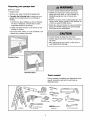 3
3
-
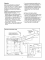 4
4
-
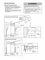 5
5
-
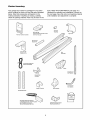 6
6
-
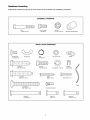 7
7
-
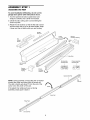 8
8
-
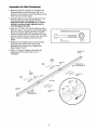 9
9
-
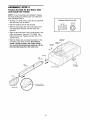 10
10
-
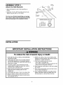 11
11
-
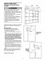 12
12
-
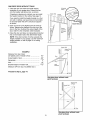 13
13
-
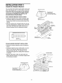 14
14
-
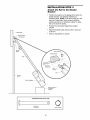 15
15
-
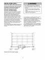 16
16
-
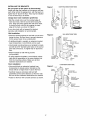 17
17
-
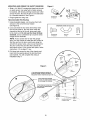 18
18
-
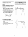 19
19
-
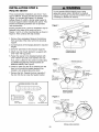 20
20
-
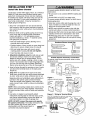 21
21
-
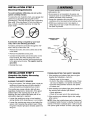 22
22
-
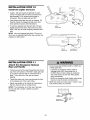 23
23
-
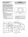 24
24
-
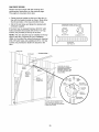 25
25
-
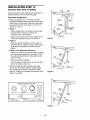 26
26
-
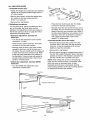 27
27
-
 28
28
-
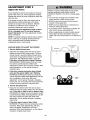 29
29
-
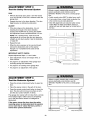 30
30
-
 31
31
-
 32
32
-
 33
33
-
 34
34
-
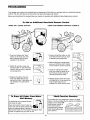 35
35
-
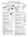 36
36
-
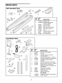 37
37
-
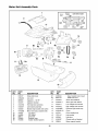 38
38
-
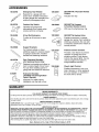 39
39
-
 40
40
-
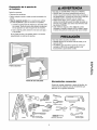 41
41
-
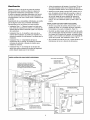 42
42
-
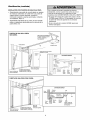 43
43
-
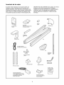 44
44
-
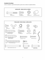 45
45
-
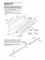 46
46
-
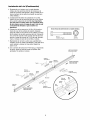 47
47
-
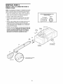 48
48
-
 49
49
-
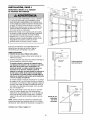 50
50
-
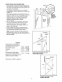 51
51
-
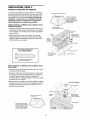 52
52
-
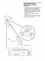 53
53
-
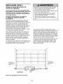 54
54
-
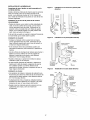 55
55
-
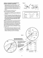 56
56
-
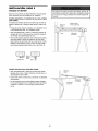 57
57
-
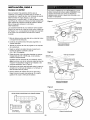 58
58
-
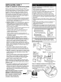 59
59
-
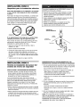 60
60
-
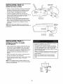 61
61
-
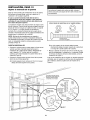 62
62
-
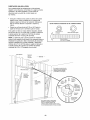 63
63
-
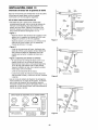 64
64
-
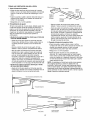 65
65
-
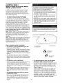 66
66
-
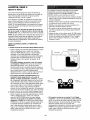 67
67
-
 68
68
-
 69
69
-
 70
70
-
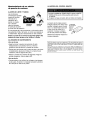 71
71
-
 72
72
-
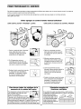 73
73
-
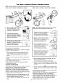 74
74
-
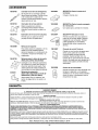 75
75
-
 76
76


Craftsman 139.53991 El manual del propietario
- Categoría
- Abridor de puerta de garage
- Tipo
- El manual del propietario
- Este manual también es adecuado para
En otros idiomas
- English: Craftsman 139.53991 Owner's manual
Documentos relacionados
-
Craftsman 13953648D El manual del propietario
-
-
-
-
-
-
-
-
Craftsman 139.53919 El manual del propietario
-