Kichler Lighting 42631CH Manual de usuario
- Tipo
- Manual de usuario

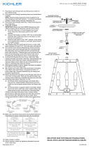
12) Pase el alambre eléctrico y el alambre de tierra a través de los estabones de la
cadena, a espacios maximos de 3 pulgadas. Pase el alambre a través del anillo
roscado, el escudete, el ojal de collar roscado, el tubo roscado y dentro de la caja
de salida.
13) Instrucciones de conexión a tierra solamente para los Estados Unidos.
(Vea la ilustracion A o B).
A) En las lámparas que tienen el fleje, de montaje con un agujero y dos
hoyuelos realzados. Enrollar el alambre a tierra de la caja tomacorriente
alrededor del tornillo verde y pasarlo por el aquiero.
B) En las lámparas con una arandela acopada. Fijar el alambre a tierra de la
caja tomacorriente del ajo de la arandela acoada y tornillo verde, y paser
por el fleje de montaje.
Si la lámpara viene con alambre a tierra. Conecter el alambre a tierra de la
lámpara al alambre a tierra de la caja tomacorriente con un conector de alambres
(no incluido) espués de seguir los pasos anteriores. Nunca conectar el alambra a
tierra a los alambres eléctros negro o blanco.
14) Haga les conexiones de los alambres (no se proveen los connectores.) La tabla
de referencia de abajo indica las conexiones correctas y los alambres correspondientes.
15) Levante el escudete hasta el cielorraso.
16) Asegure en el escudete en el lugar apretando el anillo roscado en el ojal de collar
roscado.
17) Baje la guarnición de cristal abajo, encima de las camisas de las velas.
18) Ponga las pantallas en la parte superior de las camisas de las velas.
19) Acople los cristales a la parte inferior de los brazos.
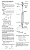
1) Screw center column on to top of fixture body.
2) Pass wire through stem and screw stem to coupling on top of center column.
3) Pass wire through remaining stems and screw stems together.
NOTE: Thread locking compound must be applied to all stem threads as noted
with symbol (3) to prevent accidental rotation of fixture during cleaning, relamping, etc.
4) Attach small loop to end of top stem.
5) TURN OFF POWER.
IMPORTANT: Before you start, NEVER attempt any work without shutting off the
electricity until the work is done.
a) Go to the main fuse, or circuit breaker, box in your home. Place the main
power switch in the “OFF” position.
b) Unscrew the fuse(s), or switch “OFF” the circuit breaker switch(s), that
control the power to the fixture or room that you are working on.
c) Place the wall switch in the “OFF” position. If the fixture to be replaced has
a switch or pull chain, place those in the “OFF” position.
6) Take threaded pipe from parts bag and screw in screw collar loop a minimum of 6 mm
(1/4”). Lock into place with hexnut.
7) Run another hexnut down threaded pipe almost touching first hexnut. Now screw
threaded pipe into mounting strap. Mounting strap must be positioned with
extruded thread faced into outlet box. Threaded pipe must protrude out the back of
mounting strap. Screw third hexnut onto end of threaded pipe protruding from back
of mounting strap.
8) Connect mounting strap to outlet box.
9) Unscrew the threaded ring from screw collar loop. Take canopy and pass over
screw collar loop. Approximately one half of the screw collar loop exterior threads
should be exposed. Adjust screw collar loop by turning assembly up or down in
mounting strap. Remove canopy.
10) After desired position is found, tighten both top and bottom hexnuts up against the
bottom and top of the mounting strap.
11) Slip canopy over screw collar loop and thread on threaded ring. Attach chain (with
fixture connected) to bottom of screw collar loop. Unscrew threaded ring, let
canopy and threaded ring slip down.
12) Weave electrical wire and ground wire through chain links no more than 3 inches
apart. Pass wire through threaded ring, canopy, screw collar loop, threaded pipe
and into outlet box.
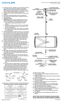
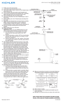
13) Grounding instructions: (See Illus. A or B).
A) On fixtures where mounting strap is provided with a hole and two raised
dimples. Wrap ground wire from outlet box around green ground screw, and
thread into hole.
B) On fixtures where a cupped washer is provided. Attach ground wire from
outlet box under cupped washer and green ground screw, and thread into
mounting strap.
If fixture is provided with ground wire. Connect fixture ground wire to outlet box
ground wire with wire connector (not provided.) after following the above steps.
Never connect ground wire to black or white power supply wires.
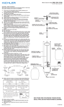
14) Make wire connections (connectors not provided). Reference chart below for
correct connections and wire accordingly.
15) Raise canopy to ceiling.
16) Secure canopy in place by tightening threaded ring onto screw collar loop.
17) Lower crystal trim down over candle sleeves.
18) Place shades on top of candle sleeves.
19) Attach crystals to bottom of arms.
1) Atornille el columna centrale en la parte superior del cuerpo del artefacto.
2) Pase el alambre a través del vástago y atornille el vástago al acoplamiento en
la parte superior del columna centrale.
3) Pase el alambre a través de los vástagos restantes y atornille los vástagos juntos.
NOTA: El compuesto para sellar roscas debe colo carse en todas las roscas de las
varillas indicadas con el símbolo (3) para evitar la rotación accidental del artefacto
durante su limpieza, cambio de bombillas, etc.
4) Acople el lazo pequeño al extremo del vástago superior.
5) APAGUE LA ALIMENTACIÓN ELÉCTRICA.
IMPORTANTE: Antes de comenzar, NUNCA trate de trabajar sin antes
desconectar la corriente hasta que el trabajo se termine.
a) Vaya a la caja principal de fusibles, o interruptor o caja de circuitos de su
casa. Coloque el interruptor de la corriente principal en posición de
apagado “OFF”.
b) Desatornille el (los) fusible (s), o coloque el interruptor o interruptores del
breaker en posición de apagado “OFF”, que controla (n) la corriente hacia
el artefacto o habitación donde está trabajando.
c) Coloque el interruptor de pared en posición de apagado “OFF”. Si el
artefacto que se va a reemplazar tiene un interruptor o cadena que se jala,
colóquelos en la posición de apagado “OFF”.
6) Seque el tubo roscado de la bolsa de piezas y atornille en el ojal de collar roscado
un minimo de 6 mm (1/4”). Inmovilice en el lugar con la tuerca hexagonal.
7) Instale otra tuerca hexagonal en el tubo roscado casi tocando la primera tuerca
hexagonal. Ahora, atornille el tubo roscado en la abrazadera de montaje. La
abrazadera de montaje se debe colocar con la rosca extruida mirando hacia la
caja de salida. El tubo roscado debe sobresalir atrás de la abrazadera de montaje.
Atornille la tercera tuerca hexagonal en el extremo del tubo roscado que sobresale
de la parte posterior de la abrazadera de montaje.
8) Conecte la abrazadera de montaje a la caja de salida.
9) Destornille el anillo roscado del ojal de collar roscado deben sobresalir
aproximadamente la mitad. Ajuste el ojal del collar roscado girando el conjunto
hacia arriba a abajo, en la abrazadera de montaje. Retire el escudete.
10) Después que encuentre la posición deseada, apriete la tuerca hexagonal superior
contra el fondo de la abrazadera de montaje.
11) Después de encontrar la posición deseada, apriete ambas tuercas hexagonales,
la superior y la inferior, arriba contra las partes superior e inferior de la abrazadera
de montaje.
MOUNTING STRAP
ABRAZADERA DE
MONTAJE
HEXNUT
TUERCA
HEXAGONAL
THREADED PIPE
TUBO ROSCADO
SCREW COLLAR LOOP
OJAL DE COLLAR
ROSCADO
CANOPY
ESCUDETE
THREADED RING
ANILLO ROSCADO
Date Issued: 10/15/10 IS-42631-US
GREEN GROUND
SCREW
CUPPED
WASHER
A
B
OUTLET BOX
GROUND
FIXTURE
GROUND
DIMPLES
WIRE CONNECTOR
(NOT PROVIDED)
OUTLET BOX
GROUND
GREEN GROUND
SCREW
FIXTURE
GROUND
Connect Black or
Red Supply Wire to:
Connect
White Supply Wire to:
Black White
*Parallel cord (round & smooth) *Parallel cord (square & ridged)
Clear, Brown, Gold or Black
without tracer
Clear, Brown, Gold or Black
with tracer
Insulated wire (other than green)
with copper conductor
Insulated wire (other than green)
with silver conductor
*Note: When parallel wires (SPT I & SPT II)
are used. The neutral wire is square shaped
or ridged and the other wire will be round in
shape or smooth (see illus.)
Neutral Wire
ARANDELA
CONCAVA
A
B
TIERRA DE LA
CAJA DE SALIDA
TORNILLO DE TIERRA,
VERDE
DEPRESIONES
TIERRA
ARTEFACTO
CONECTOR DE ALAMBRE
(NO SE PROVEE)
TIERRA DE LA
CAJA DE SALIDA
TORNILLO DE TIERRA,
VERDE
TIERRA
ARTEFACTO
Conectar el alambre de
suministro negro o rojo al
Conectar el alambre de
suministro blanco al
Negro Blanco
*Cordon paralelo (redondo y liso)
*Cordon paralelo (cuadrado y estriado)
Claro, marrón, amarillio o negro
sin hebra identificadora
Claro, marrón, amarillio o negro
con hebra identificadora
Alambre aislado (diferente del verde)
con conductor de cobre
Alambre aislado (diferente del
verde) con conductor de plata
*Nota: Cuando se utiliza alambre paralelo
(SPT I y SPT II). El alambre neutro es de forma
cuadrada o estriada y el otro alambre será de
forma redonda o lisa. (Vea la ilustracíón).
Hilo Neutral
LOOP
ANILLO
SHADE
PANTALLA
CRYSTAL
CRISTAL
CENTER COLUMN
COLUMNA CENTRALE
CRYSTAL TRIM
GUARNICIÓN
DE CRISTAl
3
3
STEM
VÁSTAGO
Transcripción de documentos
1) 2) 3) Screw center column on to top of fixture body. Pass wire through stem and screw stem to coupling on top of center column. Pass wire through remaining stems and screw stems together. NOTE: Thread locking compound must be applied to all stem threads as noted with symbol (3) to prevent accidental rotation of fixture during cleaning, relamping, etc. 4) Attach small loop to end of top stem. 5) Turn off power. IMPORTANT: Before you start, NEVER attempt any work without shutting off the electricity until the work is done. a) Go to the main fuse, or circuit breaker, box in your home. Place the main power switch in the “OFF” position. b) Unscrew the fuse(s), or switch “OFF” the circuit breaker switch(s), that control the power to the fixture or room that you are working on. c) Place the wall switch in the “OFF” position. If the fixture to be replaced has a switch or pull chain, place those in the “OFF” position. 6) Take threaded pipe from parts bag and screw in screw collar loop a minimum of 6 mm (1/4”). Lock into place with hexnut. 7) Run another hexnut down threaded pipe almost touching first hexnut. Now screw threaded pipe into mounting strap. Mounting strap must be positioned with extruded thread faced into outlet box. Threaded pipe must protrude out the back of mounting strap. Screw third hexnut onto end of threaded pipe protruding from back of mounting strap. 8) Connect mounting strap to outlet box. 9) Unscrew the threaded ring from screw collar loop. Take canopy and pass over screw collar loop. Approximately one half of the screw collar loop exterior threads should be exposed. Adjust screw collar loop by turning assembly up or down in mounting strap. Remove canopy. 10) After desired position is found, tighten both top and bottom hexnuts up against the bottom and top of the mounting strap. 11) Slip canopy over screw collar loop and thread on threaded ring. Attach chain (with fixture connected) to bottom of screw collar loop. Unscrew threaded ring, let canopy and threaded ring slip down. 12) Weave electrical wire and ground wire through chain links no more than 3 inches apart. Pass wire through threaded ring, canopy, screw collar loop, threaded pipe and into outlet box. 13) Grounding instructions: (See Illus. A or B). A) On fixtures where mounting strap is provided with a hole and two raised dimples. Wrap ground wire from outlet box around green ground screw, and thread into hole. B) On fixtures where a cupped washer is provided. Attach ground wire from outlet box under cupped washer and green ground screw, and thread into mounting strap. If fixture is provided with ground wire. Connect fixture ground wire to outlet box ground wire with wire connector (not provided.) after following the above steps. Never connect ground wire to black or white power supply wires. A B MOUNTING STRAP abrazadera de montaje HEXNUT TUERCA HEXAGONAL THREADED PIPE TUBO ROSCADO CANOPY ESCUDETE SCREW COLLAR LOOP ojal de collar roscado THREADED RING ANILLO ROSCADO LOOP ANILLO 3 3 STEM vástago CENTER COLUMN COLUMNA CENTRALE shade pantalla CRYSTAL TRIM guarnición de cristal wIrE CoNNECTor (NoT ProVIDED) oUTLET BoX GroUND FIXTUrE GroUND FIXTUrE GroUND DIMPLES GrEEN GroUND SCrEw crystal cristal oUTLET BoX GroUND GrEEN GroUND SCrEw CUPPED wASHEr 14) Make wire connections (connectors not provided). Reference chart below for correct connections and wire accordingly. Connect Black or Red Supply Wire to: Connect White Supply Wire to: Black White *Parallel cord (round & smooth) *Parallel cord (square & ridged) Clear, Brown, Gold or Black without tracer Clear, Brown, Gold or Black with tracer Insulated wire (other than green) with copper conductor Insulated wire (other than green) with silver conductor *Note: When parallel wires (SPT I & SPT II) are used. The neutral wire is square shaped or ridged and the other wire will be round in shape or smooth (see illus.) Neutral Wire 15) Raise canopy to ceiling. 16) Secure canopy in place by tightening threaded ring onto screw collar loop. 17) Lower crystal trim down over candle sleeves. 18) Place shades on top of candle sleeves. 19) Attach crystals to bottom of arms. Atornille el columna centrale en la parte superior del cuerpo del artefacto. Pase el alambre a través del vástago y atornille el vástago al acoplamiento en la parte superior del columna centrale. 3) Pase el alambre a través de los vástagos restantes y atornille los vástagos juntos. NOTA: El compuesto para sellar roscas debe colo carse en todas las roscas de las varillas indicadas con el símbolo (3) para evitar la rotación accidental del artefacto durante su limpieza, cambio de bombillas, etc. 4) Acople el lazo pequeño al extremo del vástago superior. 5) Apague la alimentación eléctrica. IMPORTANTE: Antes de comenzar, NUNCA trate de trabajar sin antes desconectar la corriente hasta que el trabajo se termine. a) Vaya a la caja principal de fusibles, o interruptor o caja de circuitos de su casa. Coloque el interruptor de la corriente principal en posición de apagado “OFF”. b) Desatornille el (los) fusible (s), o coloque el interruptor o interruptores del breaker en posición de apagado “OFF”, que controla (n) la corriente hacia el artefacto o habitación donde está trabajando. c) Coloque el interruptor de pared en posición de apagado “OFF”. Si el artefacto que se va a reemplazar tiene un interruptor o cadena que se jala, colóquelos en la posición de apagado “OFF”. 6) Seque el tubo roscado de la bolsa de piezas y atornille en el ojal de collar roscado un minimo de 6 mm (1/4”). Inmovilice en el lugar con la tuerca hexagonal. 7) Instale otra tuerca hexagonal en el tubo roscado casi tocando la primera tuerca hexagonal. Ahora, atornille el tubo roscado en la abrazadera de montaje. La abrazadera de montaje se debe colocar con la rosca extruida mirando hacia la caja de salida. El tubo roscado debe sobresalir atrás de la abrazadera de montaje. Atornille la tercera tuerca hexagonal en el extremo del tubo roscado que sobresale de la parte posterior de la abrazadera de montaje. 8) Conecte la abrazadera de montaje a la caja de salida. 9) Destornille el anillo roscado del ojal de collar roscado deben sobresalir aproximadamente la mitad. Ajuste el ojal del collar roscado girando el conjunto hacia arriba a abajo, en la abrazadera de montaje. Retire el escudete. 10) Después que encuentre la posición deseada, apriete la tuerca hexagonal superior contra el fondo de la abrazadera de montaje. 11) Después de encontrar la posición deseada, apriete ambas tuercas hexagonales, la superior y la inferior, arriba contra las partes superior e inferior de la abrazadera de montaje. 12) Pase el alambre eléctrico y el alambre de tierra a través de los estabones de la cadena, a espacios maximos de 3 pulgadas. Pase el alambre a través del anillo roscado, el escudete, el ojal de collar roscado, el tubo roscado y dentro de la caja de salida. 13) Instrucciones de conexión a tierra solamente para los Estados Unidos. (Vea la ilustracion A o B). A) En las lámparas que tienen el fleje, de montaje con un agujero y dos hoyuelos realzados. Enrollar el alambre a tierra de la caja tomacorriente alrededor del tornillo verde y pasarlo por el aquiero. B) En las lámparas con una arandela acopada. Fijar el alambre a tierra de la caja tomacorriente del ajo de la arandela acoada y tornillo verde, y paser por el fleje de montaje. Si la lámpara viene con alambre a tierra. Conecter el alambre a tierra de la lámpara al alambre a tierra de la caja tomacorriente con un conector de alambres (no incluido) espués de seguir los pasos anteriores. Nunca conectar el alambra a tierra a los alambres eléctros negro o blanco. A B CoNECTor DE ALAMBrE (No SE ProVEE) TIErrA DE LA CAjA DE SALIDA Date Issued: 10/15/10 TIErrA ArTEFACTo TIErrA ArTEFACTo 1) 2) DEPrESIoNES TorNILLo DE TIErrA, VErDE TIErrA DE LA CAjA DE SALIDA TorNILLo DE TIErrA, VErDE ArANDELA CoNCAVA 14) Haga les conexiones de los alambres (no se proveen los connectores.) La tabla de referencia de abajo indica las conexiones correctas y los alambres correspondientes. Conectar el alambre de suministro negro o rojo al Conectar el alambre de suministro blanco al Negro Blanco *Cordon paralelo (redondo y liso) *Cordon paralelo (cuadrado y estriado) Claro, marrón, amarillio o negro sin hebra identificadora Claro, marrón, amarillio o negro con hebra identificadora Alambre aislado (diferente del verde) con conductor de cobre Alambre aislado (diferente del verde) con conductor de plata *Nota: Cuando se utiliza alambre paralelo (SPT I y SPT II). El alambre neutro es de forma cuadrada o estriada y el otro alambre será de forma redonda o lisa. (Vea la ilustracíón). Hilo Neutral 15) Levante el escudete hasta el cielorraso. 16) Asegure en el escudete en el lugar apretando el anillo roscado en el ojal de collar roscado. 17) Baje la guarnición de cristal abajo, encima de las camisas de las velas. 18) Ponga las pantallas en la parte superior de las camisas de las velas. 19) Acople los cristales a la parte inferior de los brazos. IS-42631-US-
 1
1

Kichler Lighting 42631CH Manual de usuario
- Tipo
- Manual de usuario
en otros idiomas
- English: Kichler Lighting 42631CH User manual
Artículos relacionados
-
 Kichler Lighting 43519DAG Manual de usuario
-
 Kichler Lighting 43901CLP Manual de usuario
-
 Kichler Lighting 3299NI Manual de usuario
-
Kichler Lighting 43775AVI Manual de usuario
-
 Kichler Lighting 43776AVI Manual de usuario
-
 Kichler Lighting 1894NI Manual de usuario
-
 Kichler Lighting 43193AUB Manual de usuario
-
 Kichler Lighting 43234NI Manual de usuario
-
 Kichler Lighting 43723CH Manual de usuario
-
 Kichler Lighting 43618WZC Manual de usuario


