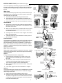
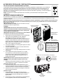
El MasterCool MCP44 es un enfriador de aire evaporativo que ha sido diseñado para brindar un alivio refrescante del calor del verano. Está equipado con un potente motor de tres velocidades para ofrecer una variedad de opciones de flujo de aire para satisfacer tus necesidades. Su tanque de agua de gran capacidad garantiza horas de enfriamiento continuo sin necesidad de rellenar. Además, cuenta con aspas ajustables para dirigir el flujo de aire donde más lo necesites.
El MasterCool MCP44 es un enfriador de aire evaporativo que ha sido diseñado para brindar un alivio refrescante del calor del verano. Está equipado con un potente motor de tres velocidades para ofrecer una variedad de opciones de flujo de aire para satisfacer tus necesidades. Su tanque de agua de gran capacidad garantiza horas de enfriamiento continuo sin necesidad de rellenar. Además, cuenta con aspas ajustables para dirigir el flujo de aire donde más lo necesites.


-
 1
1
-
 2
2
-
 3
3
-
 4
4
-
 5
5
-
 6
6
-
 7
7
-
 8
8
-
 9
9
-
 10
10
-
 11
11
-
 12
12
-
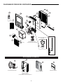 13
13
-
 14
14
-
 15
15


MasterCool MCP44 Manual de usuario
- Tipo
- Manual de usuario
- Este manual también es adecuado para
El MasterCool MCP44 es un enfriador de aire evaporativo que ha sido diseñado para brindar un alivio refrescante del calor del verano. Está equipado con un potente motor de tres velocidades para ofrecer una variedad de opciones de flujo de aire para satisfacer tus necesidades. Su tanque de agua de gran capacidad garantiza horas de enfriamiento continuo sin necesidad de rellenar. Además, cuenta con aspas ajustables para dirigir el flujo de aire donde más lo necesites.
en otros idiomas
- English: MasterCool MCP44 User manual